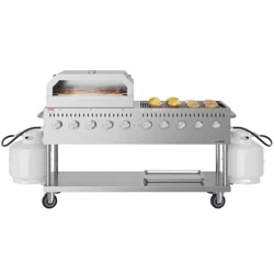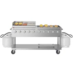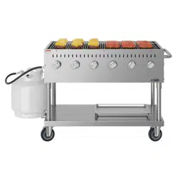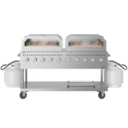
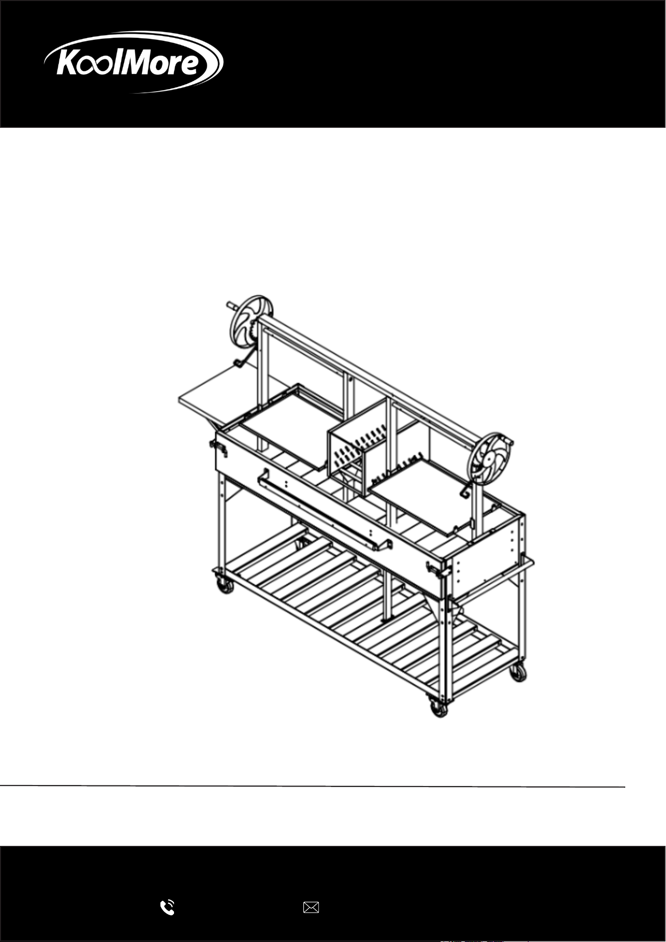
ARGENTINA GRILL
92 In. Double Argentine Santa Maria Live
Fire, Charcoal BBQ Grill in Black
INSTALLATION MANUAL
Please read these installation instructions carefully to ensure the
appliance is installed correctly and operates safely.
For any service related issues, please contact us:
718-576-6342
suppor[email protected]
Model: KM-OG-AWD-92

Stay informed with the latest information for your
KoolMore Appliance.
Scan the QR code below to access the most recent Installation Manual
on our website, which is constantly being updated and improved.
If you need any assistance or have questions, our customer support
team is here to help.
Phone- 718-576-6342 Email- suppor[email protected]
Please write down the model number and serial number below for future reference. Both numbers are located on the
rating label on the back of your unit or inside of the unit and are needed to obtain warranty service. You may also
want to staple your receipt to this manual as it is your proof of purchase and may also be needed for service
under warranty.
Model Number:
Serial Number:
Date of Purchase:
To better serve you, please do the following before contacting customer service:
If you received a damaged product, immediately contact the retailer or dealer that sold you the product.
Read and follow this Installation Manual carefully to help you install, use, and maintain your grill.
Refer to the Troubleshooting section of this manual as it will help you diagnose and solve many common issues.

3
Contents
Safety ............................................................................................ 4
Parts .............................................................................................. 6
Installation ..................................................................................... 8

4
Safety
IMPORTANT SAFETY INFORMATION
WARNING
Failure to follow these instructions may result in re, explosion, serious injury, or death. Read and
understand all safety information before assembling or using this grill.
Fuel Restrictions
• This grill is designed for use with wood and charcoal only.
• DO NOT use propane, natural gas, liquid alcohol fuels, gasoline, lighter uid, or any other accel-
erants.
• Use of unapproved fuels may cause re, explosion, or serious injury.
Location & Installation Safety
• Outdoor Use Only: This grill is intended for outdoor use only in a well-ventilated area. DO NOT
use indoors, in garages, under awnings, carports, or near enclosed structures.
• Clearance: Maintain a minimum clearance of 5 feet on all sides and above the grill from com-
bustible materials, including walls, fences, trees, decks, and furniture.
• Stable Surface: Place the grill on a solid, level, non-combustible surface such as concrete or
stone. DO NOT place on grass, wood, or other ammable surfaces.
• Wind Conditions: Do not operate the grill in strong or gusty winds, as embers and ash may be
carried and create a re hazard.
Fuel & Fire Safety
• Approved Fuels Only: Use natural lump charcoal, charcoal briquettes, and small amounts of
dry, seasoned hardwood chunks or chips.
• Lighting Method: A charcoal chimney starter is strongly recommended.
• Allow charcoal to fully ash over and turn gray before cooking.
• Never add liquid fuel to hot or burning coals.
• Never Use Lighter Fluid: Pouring lighter uid or accelerants onto hot or warm coals can cause
a ash re.
Ash Management
• Cool Before Disposal: Allow ashes to cool completely for 24–48 hours before handling or dis-
posing of them.
• Proper Disposal: Place cooled ashes in a metal container with a tight-tting lid and store away
from buildings or combustible materials.
• Fire Preparedness: Keep a re extinguisher, water source, or sand nearby at all times.
General Operating Safety
• Never Leave Unattended: Always supervise the grill while in use or while coals are hot.
• Children & Pets: Keep children and pets at a safe distance from the grill at all times.
• Hot Surfaces: All grill surfaces become extremely hot during use and remain hot after shut-
down.
• Use heat-resistant gloves or oven mitts.
• Avoid touching metal surfaces.

5
• Use Proper Tools: Always use long-handled grilling utensils to prevent burns.
• Do Not Lean Over Grill: Especially during lighting or when adjusting fuel.
• No Modications: Do not alter the grill in any way. Modications may result in injury and will
void the warranty.
• Inspect Before Use: Check the grill for loose hardware, damage, or excessive wear before each
use.
Maintenance & Fire Prevention
• Clean cooking grates and remove grease buildup after each use.
• Excess grease or ash accumulation can cause are-ups or re.
• Ensure all ashes are fully cooled before cleaning the rebox.
IMPORTANT NOTE
Always follow the assembly instructions specic to your model. Improper assembly or misuse can
result in unsafe operation and void the warranty.
6
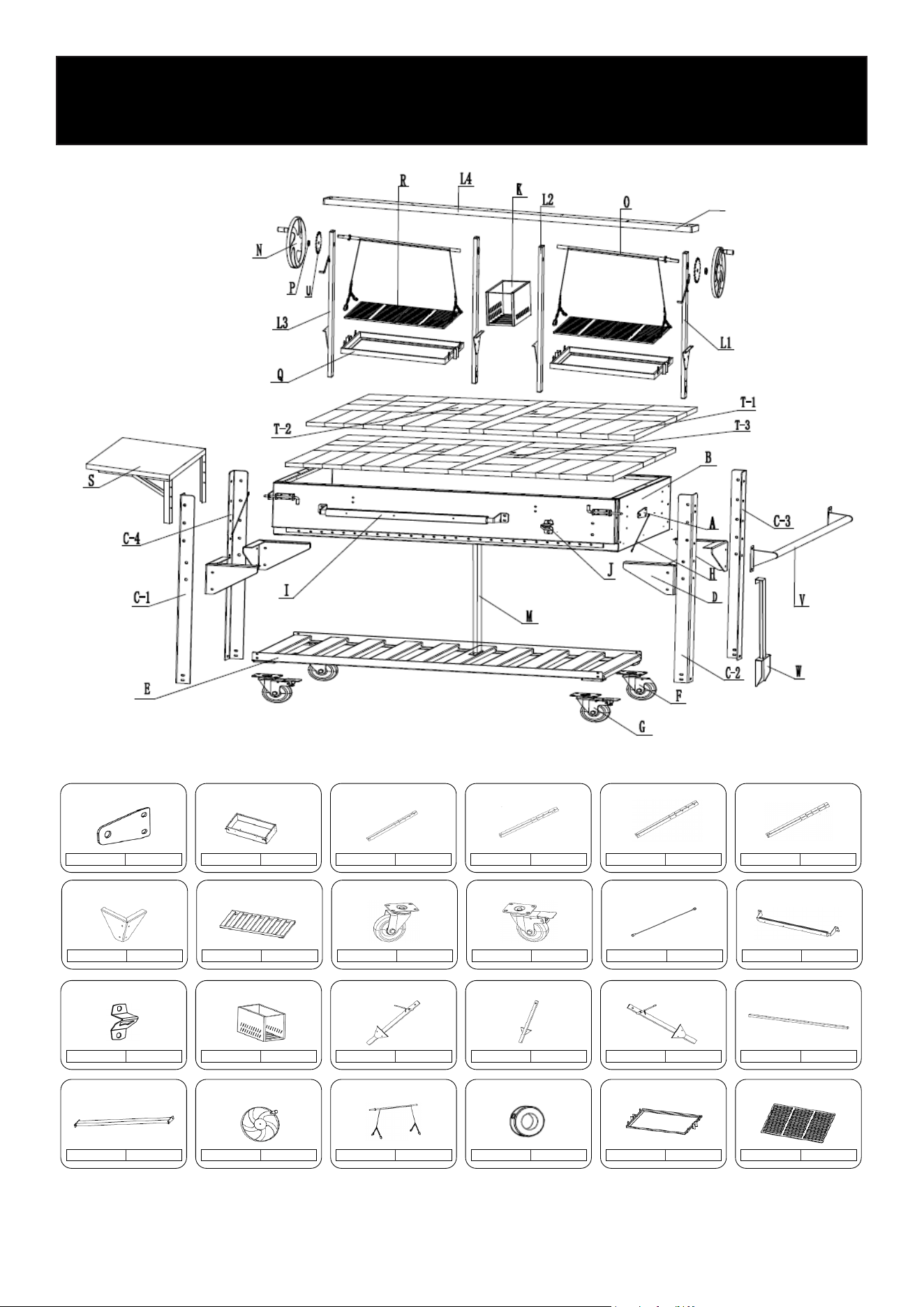
Parts
Parts List
Locking Plate
A 2
Stove Tub
B 1
Leg
C-1 1
Leg
C-2 1
Leg
C-3 1
Leg
C-4 1
Couplers
D 4
Bottom Tray
E 1
Caster
F 2
Caster
G 2
Steel Wire Rope
H 2
Wooden Handle
I 1
Bottle Opener
J 1
Fire Box
K 1
Left Post
L-1 1
Center Post
L-2 2
Right Post
L-3 1
Top Beam
L-4 1
Tub Support Bar
M 1
Flywheel
N 2
Axle System
O 2
Axle Cover
P 4
Grill Frame
Q 2
Cooking Grill
R 2

7
Side Shelf
S 1
Fire Brick
T-1 66
Fire Brick
T-2 4
Fire Brick
T-3 4
Gear
U 2
Tool Bar
V 1
230 × 115 × 20
230 × 115 × 20
30 × 115 × 20
Shovel
W 1
Screws
M6 x 14
AA 83
M8 x 12
BB 18
M6 x 40
DD 8
8
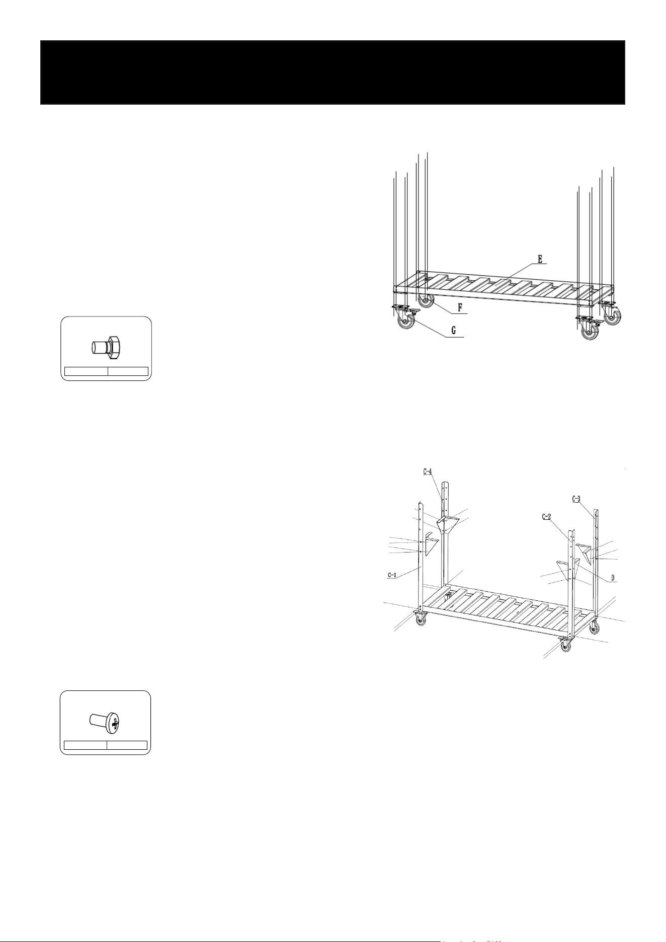
Step 1: Install the Casters
• Install two (2) casters labeled G on the front side of
the bottom tray (E).
• Install two (2) casters labeled F on the rear side of
the bottom tray (E).
• Secure each caster (G and F) using four (4) M8 × 12
screws (BB).
• Before fully tightening the screws, ensure each caster
is in the locked position.
• Once properly aligned, tighten all screws securely.
Installation
M8 x 12
BB 16
Step 2: Install the Legs and Couplers
• Install four (4) legs labeled C onto the bottom tray (E),
following the numbered markings.
• Secure each leg (C) using three (3) M6 × 14 screws
(AA).
• Attach one (1) coupler (D) to each leg (C).
• On the corner legs (C2 and C3), install the rst screw
of each coupler together with the tool bar (V), as ref-
erenced in Step 8.
• Secure each coupler (D) using four (4) M6 × 14
screws (AA).
• Ensure all screws are tightened securely after align-
ment.
M6 x 14
AA 26
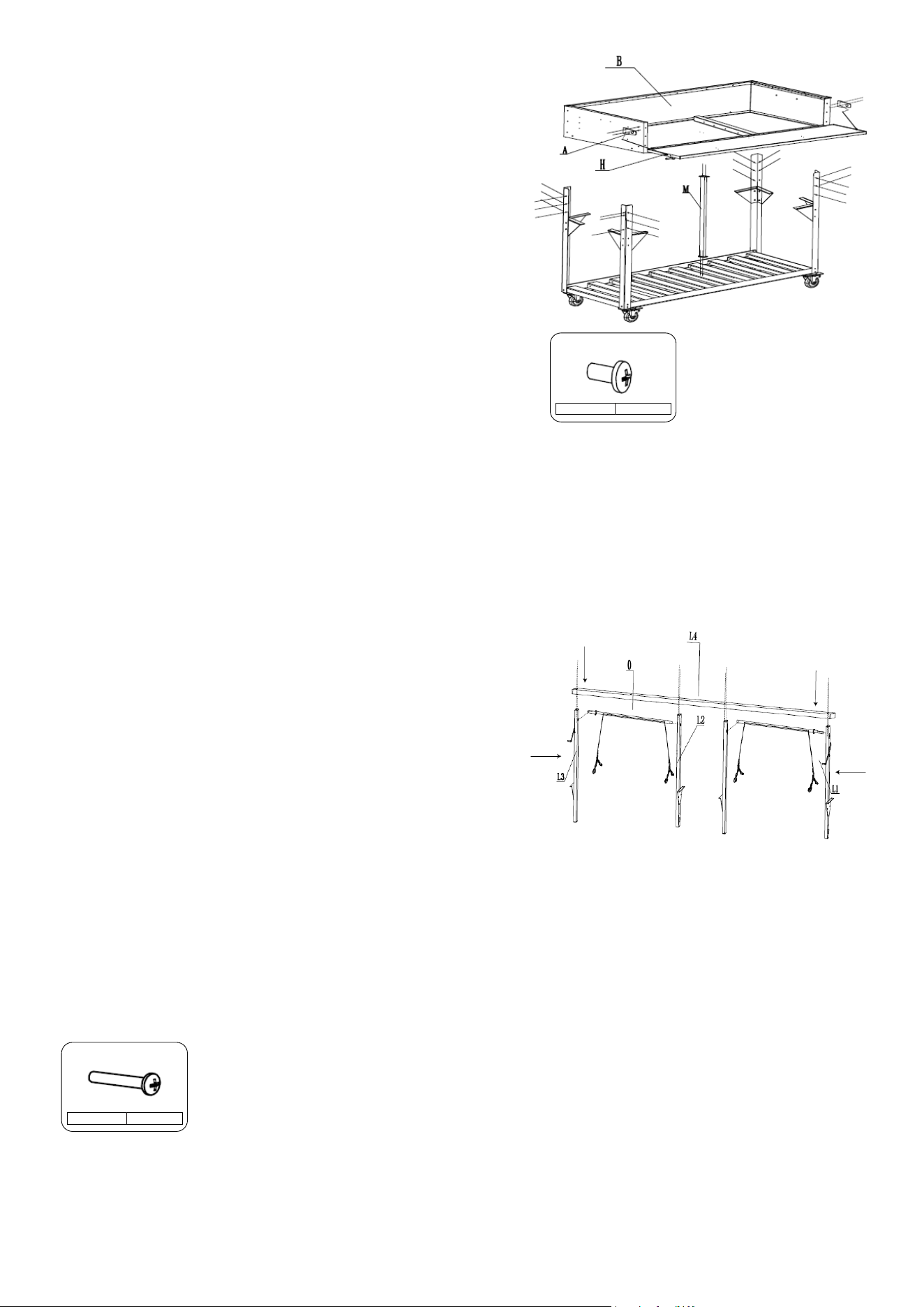
Step 3: Install the Stove Tub Bar Support and Stove Tub
• Attach the stove tub bar support (M) to the bottom
tray (E) as shown in the diagram.
• Secure it using four (4) M6 × 14 screws (AA).
• Install two (2) screws into the bottom tray and two (2)
screws into the stove tub (B).
• Assemble the stove tub (B) by attaching it to the four
(4) legs (C).
• At each corner, secure the stove tub (B) using six (6)
M6 × 14 screws (AA).
• On the corner legs (C2 and C3), install the nal screw
together with the tool bar (V), as referenced in Step 8.
• Before installing the stove tub (B), remove the locking
plates (A) and steel wire rope (H).
• After the stove tub (B) is fully installed, reinstall the
locking plates (A) and steel wire rope (H).
• Secure each locking plate (A) using two (2) M6 × 14
screws (AA).
NOTE: The screw referenced in this step also secures the
stove tub (B) at the aligned corner.
M6 x 12
AA 26
Step 4: Install the Top Beams and Posts
• Attach the Top Beam (L4) to the Right Post (L1) and
Left Post (L3).
• Secure each connection using two (2) M6 × 40
screws (DD).
• Attach one (1) Axle System (O) to the Right Post (L1).
• Attach the Center Post – Right (L2).
• Secure the Center Post – Right (L2) to the Top Beam
(L4) using two (2) M6 × 40 screws (DD).
• Repeat the same installation steps for the opposite
side.
Steel Wire Adjustment:
During assembly, the steel wire rope may become loose.
Loop the steel wire around the center screw as shown in
the diagram, then tighten the screw as needed to remove
any slack.
M6 x 40
DD 8
9
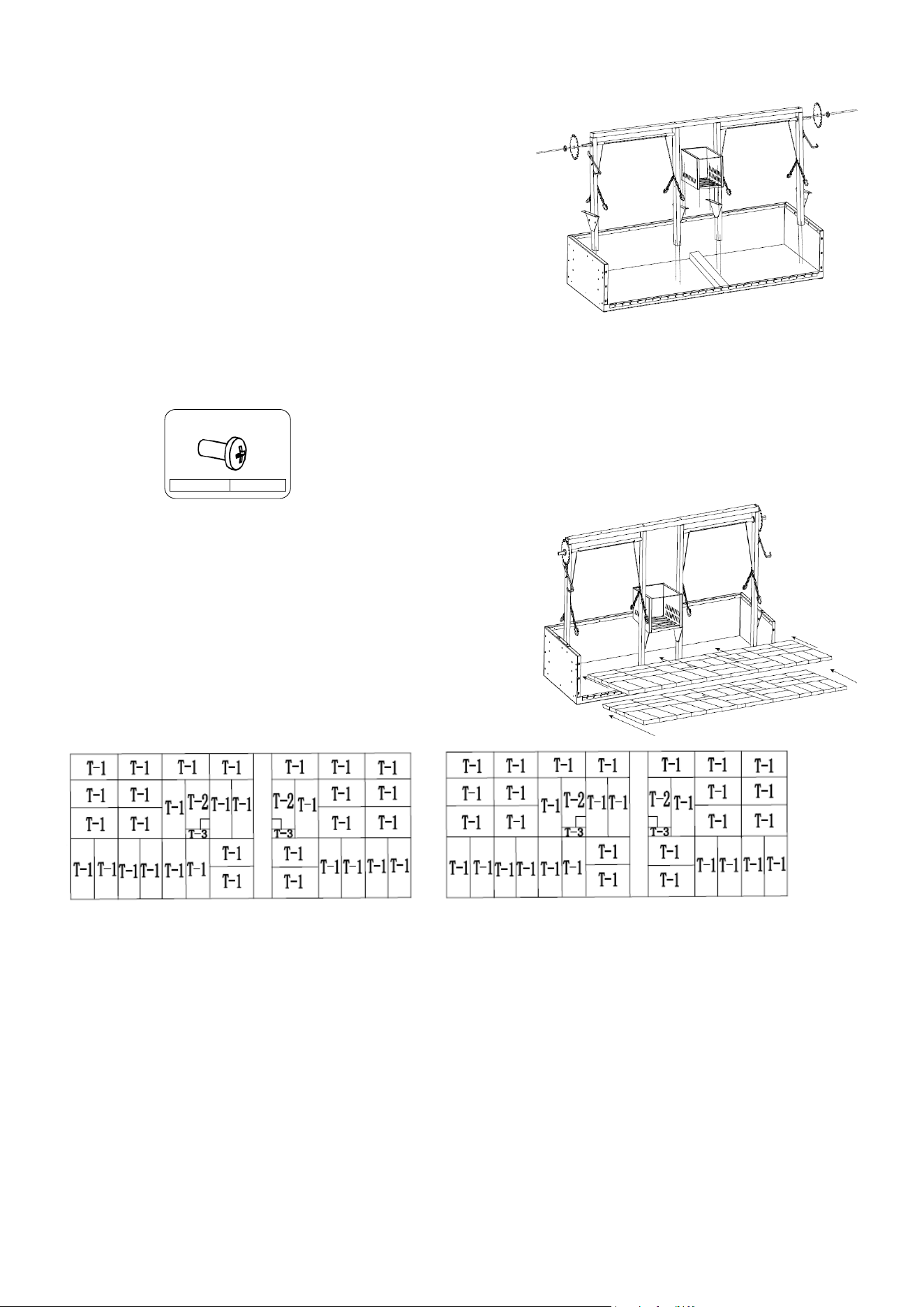
Step 5: Attach the Frame Assembly and Fire Box
• Position the assembled frame from Step 4 onto the
stove tub base, aligning all mounting holes as shown
in the diagram.
• Secure the Right Post (L1) and Left Post (L3) using
four (4) M6 × 16 screws (AA).
• Install two (2) M6 × 16 screws (AA) under the Stove
Tub (B), aligning them with the lower section of the
Left Center Post (L2).
• Attach the Fire Box (K) to the Center Posts (L2) using
ve (5) M6 × 16 screws (AA).
• Install the Gear (U) on both the left and right sides,
and secure it using the Axle Cover (P).
• Ensure all screws are properly aligned and fully tight-
ened.
M6 x 14
AA 15
Step 6: Install the Fire Bricks
• Place the Underlayer Fire Bricks (T) directly into the
Stove Tub (B), following the Bottom Fire Brick Layout
shown in the diagram.
• Once the bottom layer is properly positioned, place
the Top Layer Fire Bricks (T) on top, following the Top
Fire Brick Layout shown.
• Ensure all bricks are aligned evenly and seated at
inside the Stove Tub (B) before proceeding.
Top Fire Brick Layout Bottom Fire Brick Layout
10
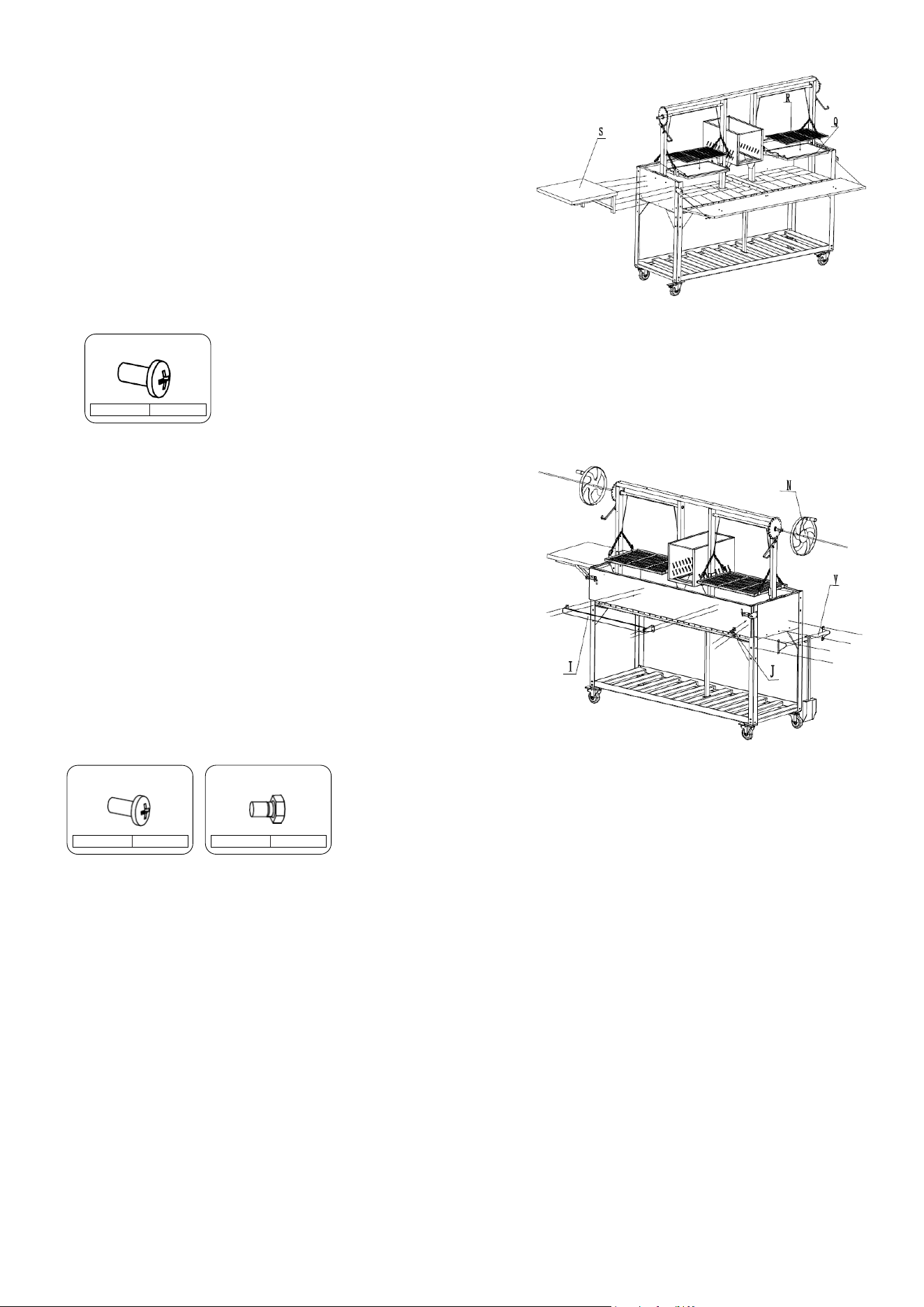
Step 7: Install the Grill Components and Side Shelf
• Place the Cooking Grill (R) onto the Grill Frame (Q) as
shown in the diagram.
• Repeat this step for both sides.
• Connect the Grill Frame (Q) by securing the stainless
steel chain to the Axle System (O).
• Repeat for both sides.
• Attach the Side Shelf (S) using six (6) M6 × 14 screws
(AA).
• After installation, ensure all components are properly
aligned and securely fastened.
M6 x 14
AA 6
Step 8: Install the Fly Wheel and Accessories
• Attach the Fly Wheel (N) to the Gear (U) on both
sides.
• Secure each side using one (1) M8 × 12 screw (BB).
• Attach the Bottle Opener (J) using two (2) M6 × 16
screws (AA).
• Attach the Wooden Handle (I) using four (4) M6 × 16
screws (AA).
• Install the Tool Bar (V) and secure it using four (4) M6
× 16 screws (AA).
• Ensure all components are properly aligned and all
screws are fully tightened.
M6 x 14
AA 10
11
M8 x 12
BB 2

12
LIMITED WARRANTY
KoolMore Supply Inc. extends a limited warranty to the original purchaser, guaranteeing that this KoolMore product is
free from manufacturing defects in material or workmanship for one year from the date of purchase.
Should you discover any such defect within the warranty period, KoolMore Supply Inc. reserves the right to repair or re-
place the product without charge, or to cover the cost of replacement parts and repair labor needed to correct defects
present at the time of purchase or resulting from regular usage, when the appliance has been installed, operated, and
maintained as per the instructions provided.
At its sole discretion, KoolMore Supply Inc. may decide to replace the product. In such an event, your replacement
appliance will carry the warranty for the remaining term of the original unit’s warranty period.
This warranty is valid exclusively to the original purchaser of the product and only applicable within the United States.
The warranty commences from the date of original consumer purchase. Proof of the original purchase date will be
required to obtain service under this warranty.
Under this limited warranty, your sole and exclusive remedy will be product repair, as outlined above. All services must
be provided by a KoolMore designated service company.
To claim warranty or request repair service:
Email [email protected]. Please include your name, address, phone number, warranty repair request, and a copy
of your proof of purchase receipt. Alternatively, visit koolmore.com and use the Contact Us page. A KoolMore custom-
er service representative will promptly arrange service for your appliance.
We thank you for choosing KoolMore.
WARRANTY EXCLUSIONS
This limited warranty will not cover:
1. Failure of the product to perform during power failures or interruptions,
or due to inadequate electrical service.
2. Damage incurred during transportation or handling.
3. Damage caused by accidents, vermin, lightning, winds, re, oods, or acts of God.
4. Damage resulting from accidents, alterations, misuse, abuse, improper installation, repair, or maintenance. This
includes using any external device that alters or converts the voltage or frequency of electricity.
5. Unauthorized product modications, repairs by unauthorized centers, or use of non-approved replacement parts.
6. Abnormal cleaning and maintenance not aligned with the user’s manual.
7. Use of incompatible accessories or components.
8. Any costs associated with repairs or replacements under these excluded circumstances shall be the responsibility
of the consumer.
WARRANTY