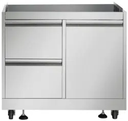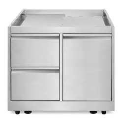
GRILL CABINET
COS-GCN323SS
READ AND SAVE THESE INSTRUCTIONS.
FOR RESIDENTIAL USE ONLY.
PLEASE LEAVE THESE INSTRUCTIONS WITH THIS UNIT FOR
THE OWNER.
PLEASE RETAIN THESE INSTRUCTIONS FOR FUTURE
REFERENCE.
IMPORTANT:
INSTALLER:
OWNER:
Rev.25.06
INSTALLATION MANUAL

2
THANK YOU FOR YOUR PURCHASE
Thank you for your purchase. We know that you have many brands and
products to choose from and we are honored to know that you have decided
to take one of our products into your home and hope that you enjoy it.
COSMO Appliances are designed according to the strictest safety and
performance standard for the North American market. We follow the most
advanced manufacturing philosophy. Each appliance leaves the factory after
thorough quality inspection and testing. Our distributors and our service
partners are ready to answer any questions you may have regarding how to
install, use and care for your products. We hope that this manual will help you
learn to use the product in the safest and most effective manner.
Before using this product, please read through this manual carefully. Keep
this user manual in a safe place for future reference. Please ensure that other
persons using this product are familiar with these instructions as well.
If you have any questions or concerns, please contact the dealer from whom you
purchased the product, or contact our Customer Support at:
1-888-784-3108
Reach us online at:
www.cosmoappliances.com

3
TABLE OF CONTENTS
Warnings .......................................................................................................... 4
Parts Explosive ................................................................................................. 5
Dimensions ...................................................................................................... 10
Cabinet Installation ........................................................................................ 12
Outdoor Grill Installation .............................................................................. 23
Warranty and Service ................................................................................... 29

WARNINGS
Warnings
These are the most critical warnings summarized below.
•
If the instructions in this manual are not followed exactly, a fire or
explosion may result, causing property damage, personal injury
or death.
• Installation of this appliance must be done by a qualified, service agency
or gas supplier.
What to do if you smell gas leaking
• Do not light any appliance
• Do not touch an electrical switch
• Immediately call the gas supplier from a neighbor’s phone
• Follow the gas supplier’s instructions
• If you cannot reach the gas supplier, call the fire department
4
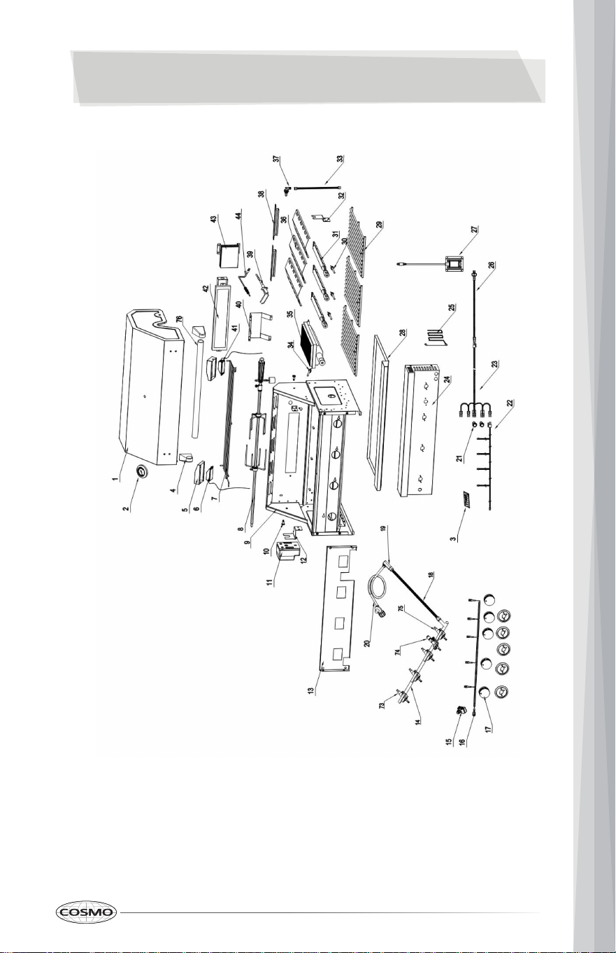
EXPLODED VIEW OF PARTS
5
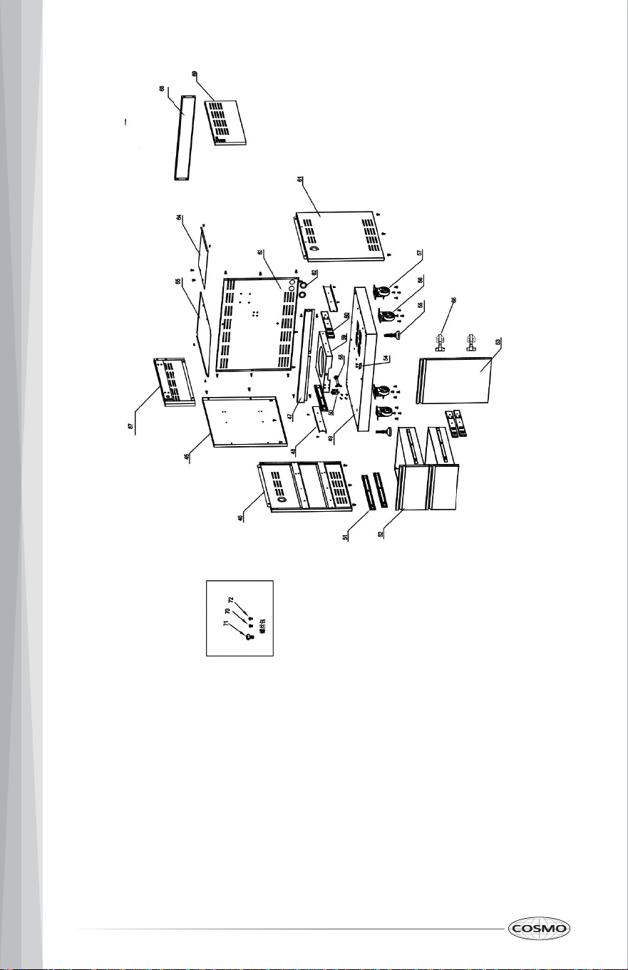
6
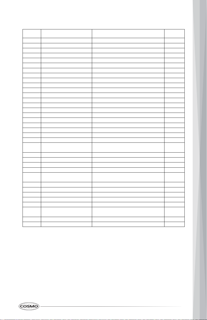
Parts List
Explosive
#
Part #
Part Name
Quantity
1
22.99.008092-000-A0
Grill Top Cover
1
2
05.99.008024-000-A0
Thermometer
1
3
08.01.008041-000-A0
logo
1
4
12.02.000070-000-A0
left handle holder
1
5
04.01.008107-000-A0
Light Cover
2
6
07.04.008001-000-A0
Light #1
1
7
13.99.008002-000-A0
Top warming rack
1
8
05.99.008011-000-A0
Rotisserie
1
9
22.99.009207-000-A0
Grill Cavity
1
10
06.07.008002-000-A1
Top cover rotary pin
2
11
07.14.008001-000-A0
Motor
1
12
04.01.008057-000-A0
Motor holder
1
13
04.03.008002-000-A1
Burner valve holding plate
1
14
22.99.009209-000-A0
Main manifold
1
15
07.07.008004-000-A0
5-point Spark Module
1
16
07.06.008003-000-A0
Main burner ignition harness
1
17
14.01.008001-000-A0
Main Burner Knob
5
18
11.01.008001-000-A0
corrugated pipe
1
19
05.07.008001-000-A0
Embedded joint
1
20
07.99.000266-000-A0
Gas regulator and gas pipe
1
21
07.02.008012-000-A0
Metal push button
2
22
07.06.008006-000-A0
Main burner knob light wiring
1
23
07.06.008002-000-A0
Main switch wiring
1
24
19.07.008002-000-A0
Grill control panel
1
25
05.09.008002-000-A0
match holder
1
26
07.06.008005-000-A0
Main burner power plug
1
27
07.14.008002-000-A0
American-standard transformer
1
28
20.01.008015-000-A2
Grease tray
1
29
13.02.008002-000-A0
Cooking rack
1
30
10.09.008009-000-A0
Main burner electrode
3
31
10.01.008002-000-A2
Tube burner
3
32
04.01.008058-000-A0
Rotisserie holder
1
33
10.04.008002-000-A0
Back broil burner corrugated pipe
1
34
10.09.008010-000-A0
Front broil burner electrode
1
35
10.10.008007-000-A0
Infrared broil burner
1
7

36
04.01.008051-000-A0
flame tamer
3
37
10.05.008002-000-A0
Back broil burner orifice - LP
1
38
20.01.008014-000-A1
flame transferring welding plate
2
39
10.09.008004-000-A0
Back broiler burner electrode
1
40
04.01.008060-000-A1
Back broiler burner protection cover
1
41
07.04.008002-000-A0
Light #2
1
42
10.99.008001-000-A0
Back broil burner
1
43
04.01.008053-000-A0
gas-collecting hood
1
44
10.99.008002-000-A0
Temperature rod
1
45
20.01.008086-000-A0
Clapboard welding part
1
46
20.01.008082-000-A0
Left side panel A welding assembly
1
47
20.01.008087-000-A0
beam welding assembly
1
48
04.01.008119-000-A0
LP tank supporting slide
2
49
20.01.008079-000-A0
tank bottom welding assembly
1
50
05.17.008003-000-A0
Snap bolt
1
51
05.14.008001-000-A0
Slideway
4
52
22.99.009199-000-A0
Drawer assembly
2
52.1
20.01.008051-000-A0
drawer front panel welding plate
2
52.2
04.01.008179-000-A0
drawer front panel lining
2
52.3
04.01.008180-000-A0
drawer middle plate
2
52.4
04.01.008181-000-A0
drawer bottom plate
2
53
22.99.009217-000-A0
Door assembly
1
54
04.01.002596-000-A1
Door barrier strip
1
55
05.01.008004-000-A0
Supporting leg
2
56
05.10.000122-000-A0
Fixed caster
2
57
05.10.000123-000-A0
Universal caster with Brake
2
58
05.13.008153-000-A0
Tank fixing rod
1
59
04.01.008117-000-A0
Tank bottom support
1
60
05.14.008012-000-A0
14" Sliders
4
61
20.01.008080-000-A0
Right side panel A welding assembly
1
62
06.08.008078-000-A0
Rubber gasket
4
63
20.01.008084-000-A0
Back panel A welding assembly
1
64
04.01.008183-000-A0
gas tank heat shield
1
65
04.01.008182-000-A0
Laminate board
1
66
05.03.008001-000-A0
Door Hinge
2
8

67
20.01.008083-000-A0
Left side panel B welding assembly
1
68
20.01.008085-000-A0
Back Panel B welding assembly
1
69
20.01.008081-000-A0
Right side panel B welding assembly
1
70
06.10.000022-000-A0
5/32“Philips thumb head screw
52
71
06.02.000093-000-A0
1/4“*14 Philips thumb head screw with anti-
slip design
59
72
06.11.008056-000-A0
5/32" *8 flat head screw
12
73
09.01.008008-000-A0
front broil burner valve
1
74
09.04.008003-000-A0
back broil burner valve
1
75
09.01.008007-000-A0
main burner valve
3
76
12.01.008002-000-A0
Top cover handle
1
77
04.01.002580-000-A0
cabinet back connecting plate
2
9
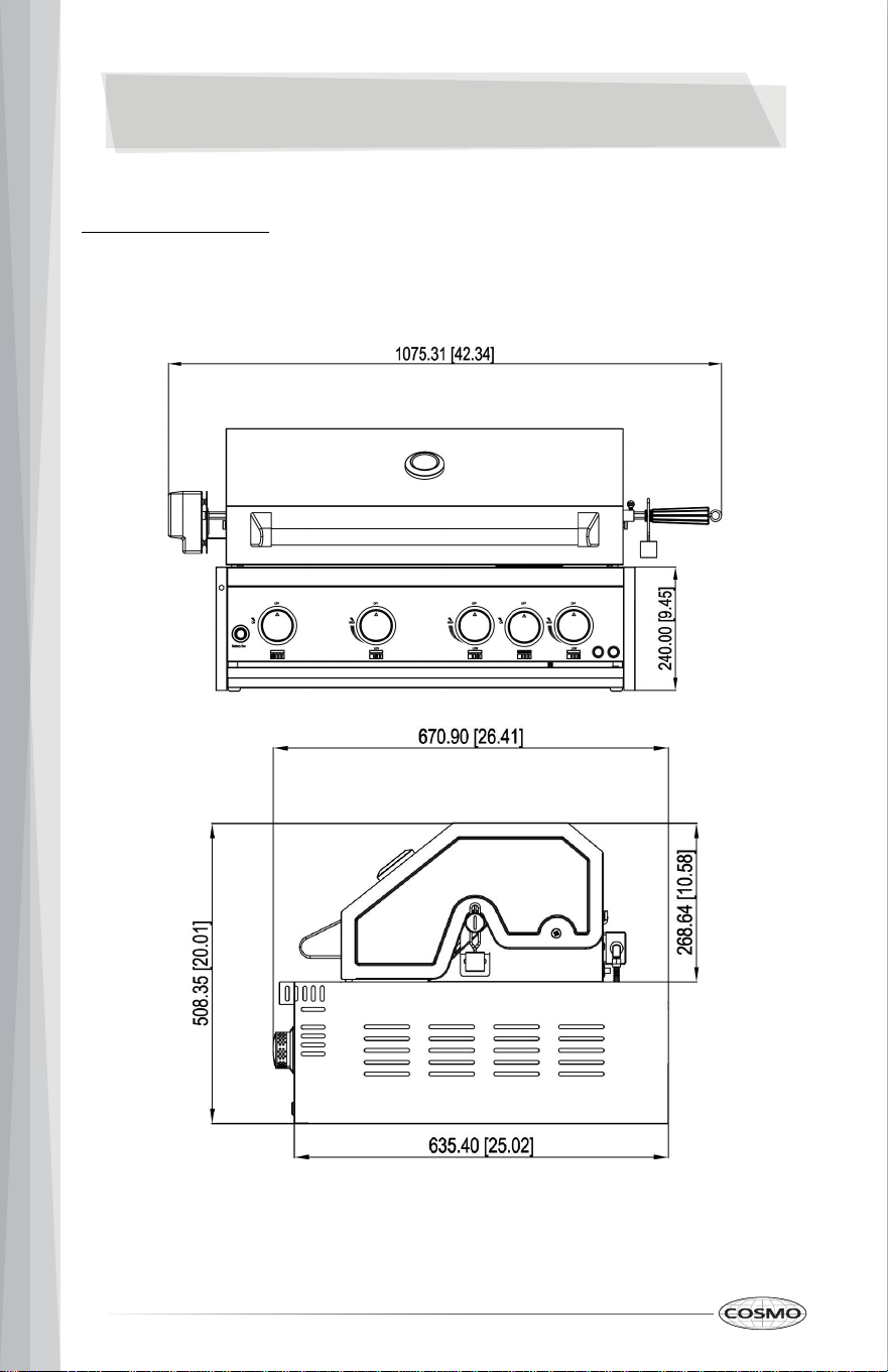
DIMENSIONS
Product Dimensions
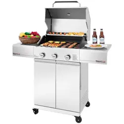
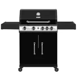
COS-BGGN325K Cosmo Outdoor BBQ Grill
10
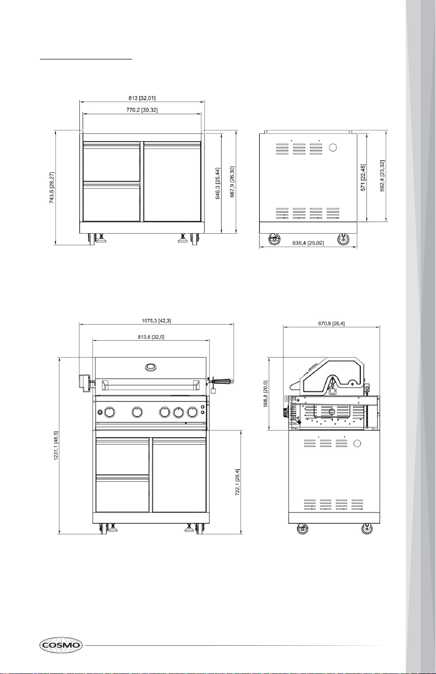
Product Dimensions
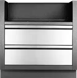
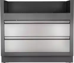
COS-GCN323SS Cosmo Outdoor Grill Cabinet
Outdoor Grill & Cabinet
11
CABINET INSTALLATION
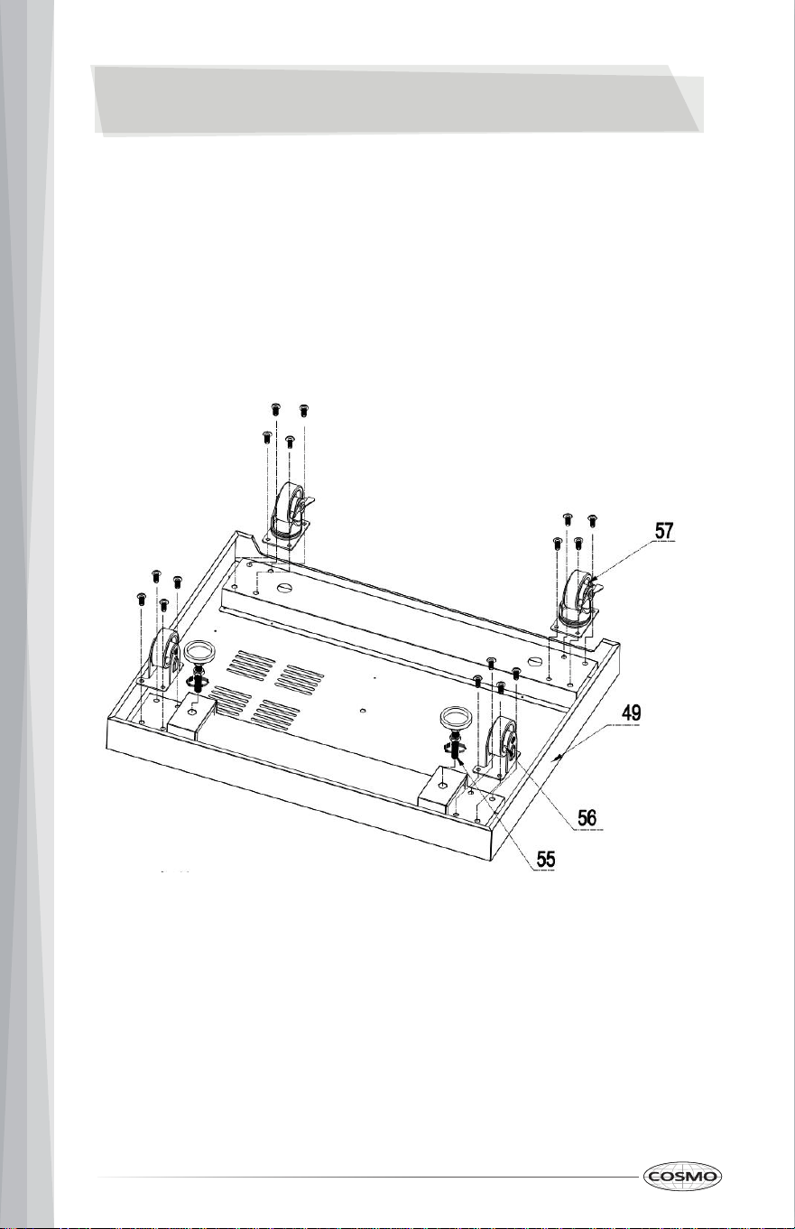
Step 1
1. Flip the bottom base welding assembly (Part #49) so in order to install legs
and casters
2. Use 16 pcs ¼” *14 Philips thumb head screw with anti-slip design (Part #71)
to install 2 pcs supporting legs (Part #55), 2 pcs fixed casters (Part #56) and
2 pcs universal casters with brake (Part #57)
12
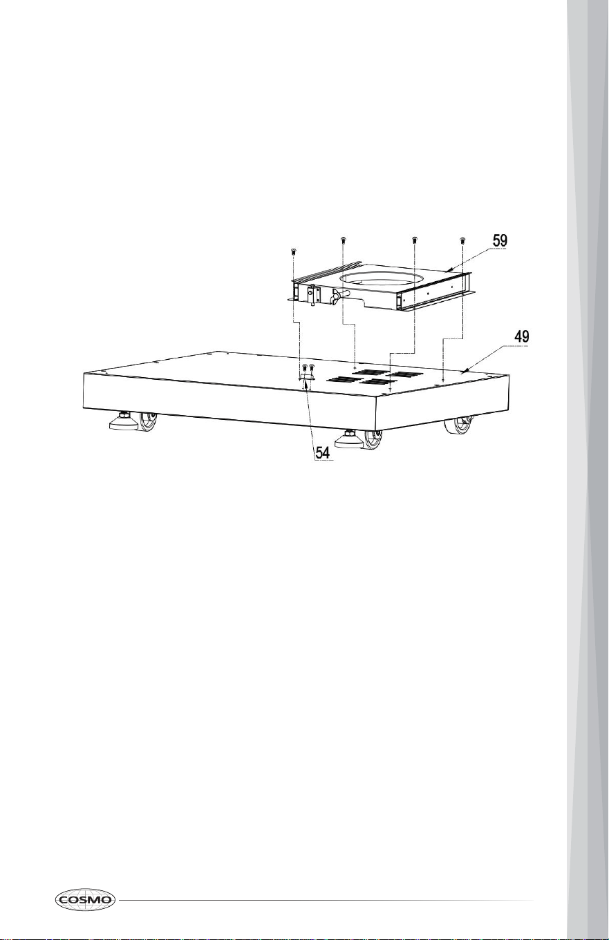
Step 2
1. Flip back the bottom base after casters and legs are installed;
2. Use 4 pcs 5/32” *8 flat head screw (Part # 72) to connect Tank bottom
support (Part # 59) to bottom base welding assembly (Part # 49);
3. Use 2 pcs 5/32” *8 flat head screw (Part # 72) to connect Door barrier strip
(Part # 54) to bottom base welding assembly (Part #49);
13
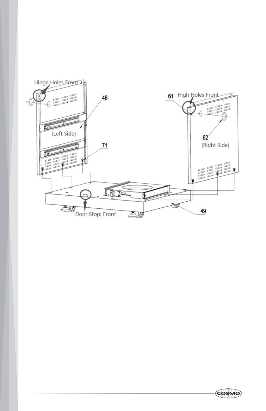
Step 3
1. Use 6 pcs 1/4“*14 Philips thumb head screw with anti-slip design (Part #71) to
Left side panel A welding assembly (Part #46) and Right-side panel A
welding assembly (Part # 61) to bottom base welding assembly (Part #49);
2. Attach 2 pcs Rubber gaskets to related position on Part #46 and Part #61;
14
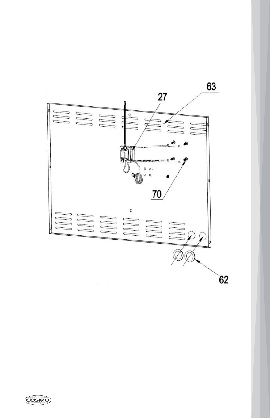
Step 4
1. Use 4 pcs 5/32” *8 flat head screw (Part # 72) to install American-standard
transformer (Part # 27) on Back panel A welding assembly (Part # 63); Do
not break the power plug on the bottom and the buckle on the top.
2. Attach 2 pcs Rubber gasket (Part # 62) to related position on Part # 63;
15
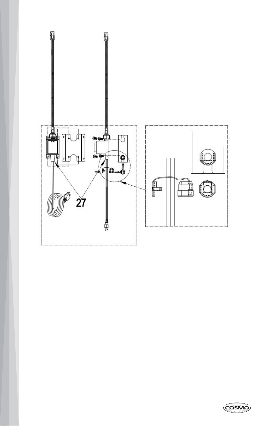
Layout of transformer installation
16
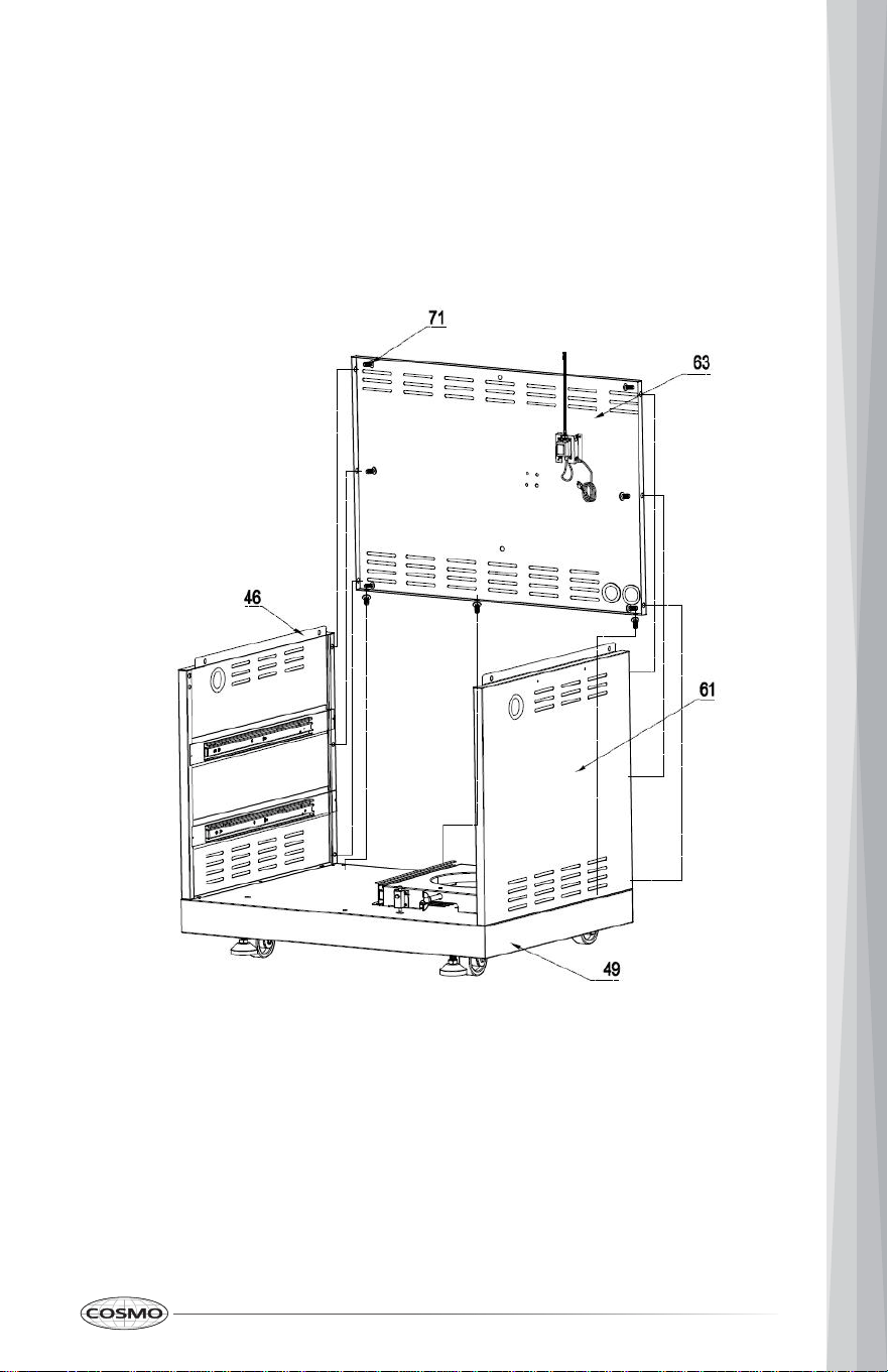
Step 5
1. Use 3 pcs 1/4“*14 Philips thumb head screw with anti-slip design (Part #71) to
install Back panel A welding assembly (Part # 63) to bottom base welding
assembly (Part # 49);
2. Use 3 pcs 1/4“*14 Philips thumb head screw with anti-slip design (Part #71) to
connect Back panel A welding assembly (Part # 63) with Part # 46 and # 61
17
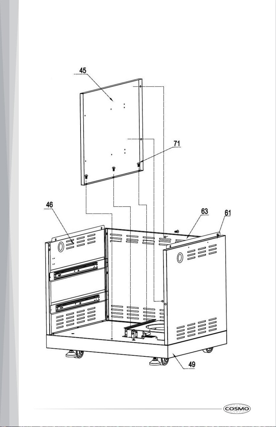
Step 6
1. Use 5 pcs 1/4“*14 Philips thumb head screw with anti-slip design (Part #71) to
connect Clapboard welding part (Part # 45) with Part #49 and #63;
18
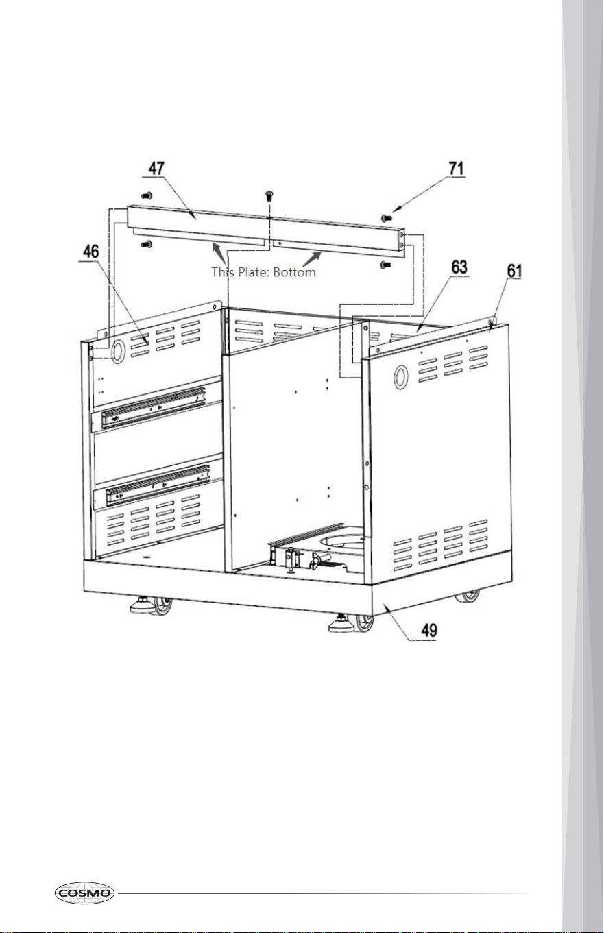
Step 7
1. Use 4 pcs 1/4“*14 Philips thumb head screw with anti-slip design (Part #71) to
connect Beam welding assembly (Part # 47) with Part #46 and #61.
19
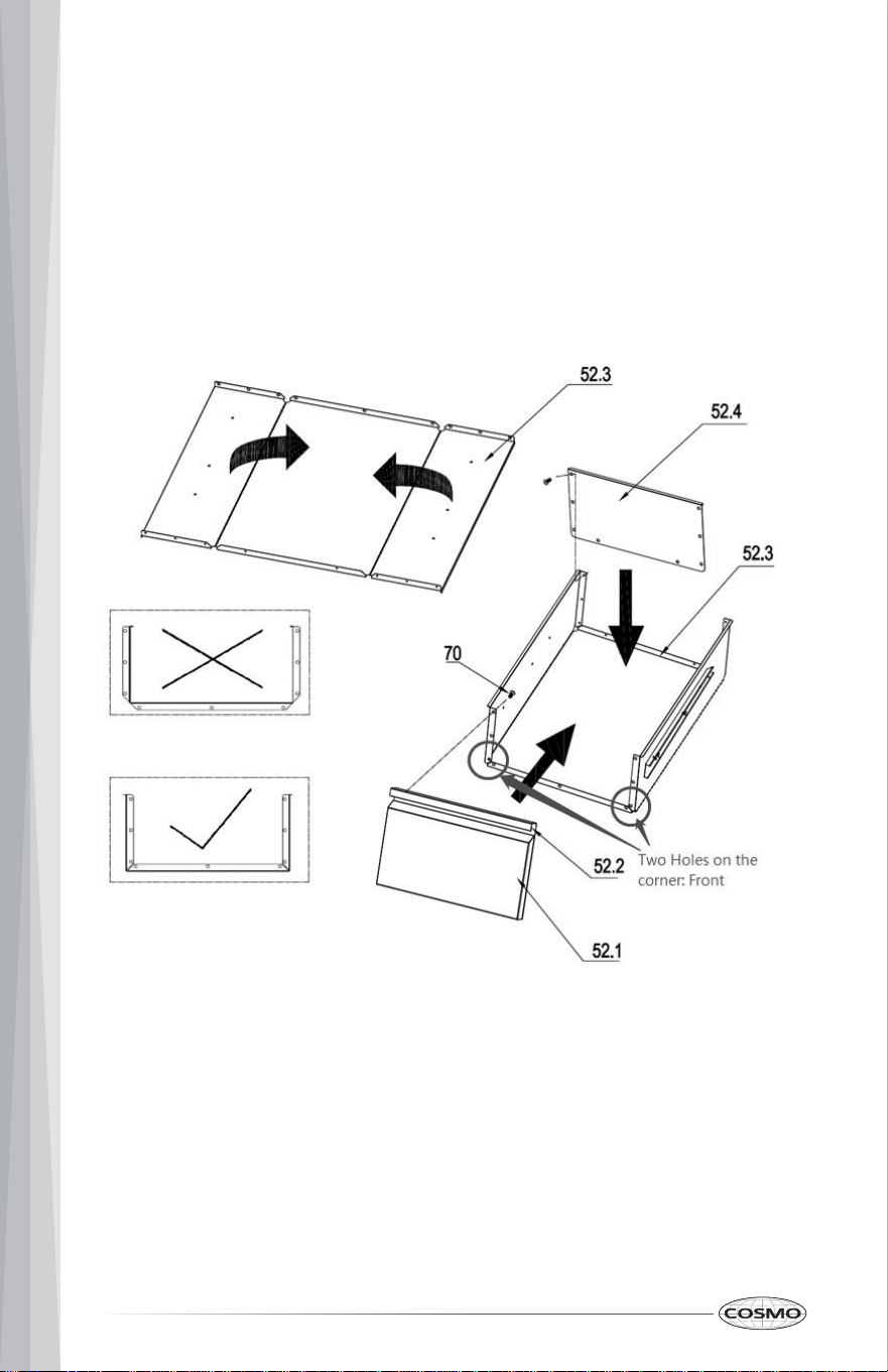
Step 8
1. Check the edge of the middle plate of the drawer assembly (Part #52) and
make sure the side with edge is facing up; otherwise you will get to wrong
folding direction (see the picture below with wrong folding direction with
“×”). Be careful with the folding process.
2. Use 8 pcs 5/32 flat Philip’s screw heads (Part # 70) install the bottom plate
of drawer assembly (Part# 52.4) to the middle plate (Part# 52.3)
3. Use 8 pcs 5/32 flat Philip’s screw heads (Part # 70) install the front plate of
drawer (Part# assembly to the middle plate (Part# 52.1 and 52.2)
20
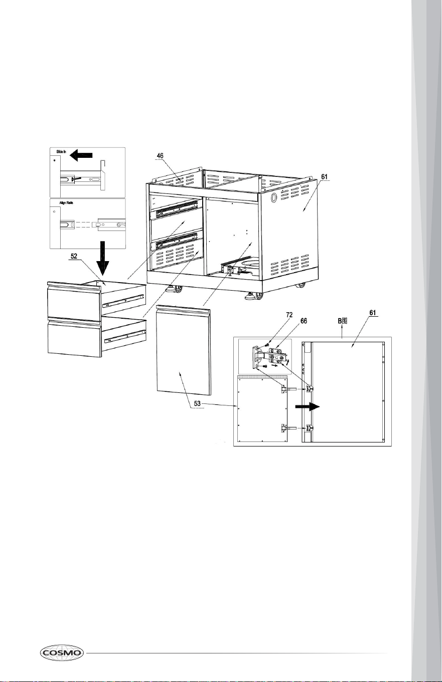
Step 9
1. Insert 2 pcs drawer assemblies (Part #52) into cabinet body;
2. Divide the two parts from door hinge (Part #66) and use 5/32” *8 flat head
screw (Part #72) to install them to right side panel (Part #61) and cabinet
door (Part #53)
3. Follow the requirement in the picture to install cabinet door (Part # 53)
21
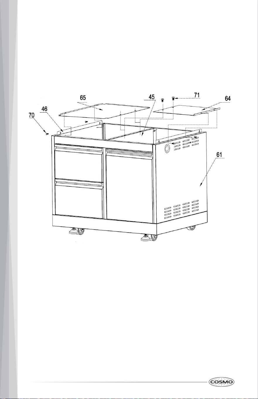
Step 10
1. Use 2 pcs 5/32" *8 flat head screw (Part # 72) to install laminate board (Part
#65) to Left side panel A welding assembly (Part #46);
2. Use 2 pcs 5/32" *8 flat head screw (Part # 72) to install gas tank heat shield
(Part #64) to Right side panel A welding assembly (Part #61)
3. Use 2 pcs 1/4“*14 Philips thumb head screw with anti-slip design (Part #71) to
install Part #64 and Part #65 to Clapboard welding part (Part #45)
22
OUTDOOR GRILL INSTALLATION
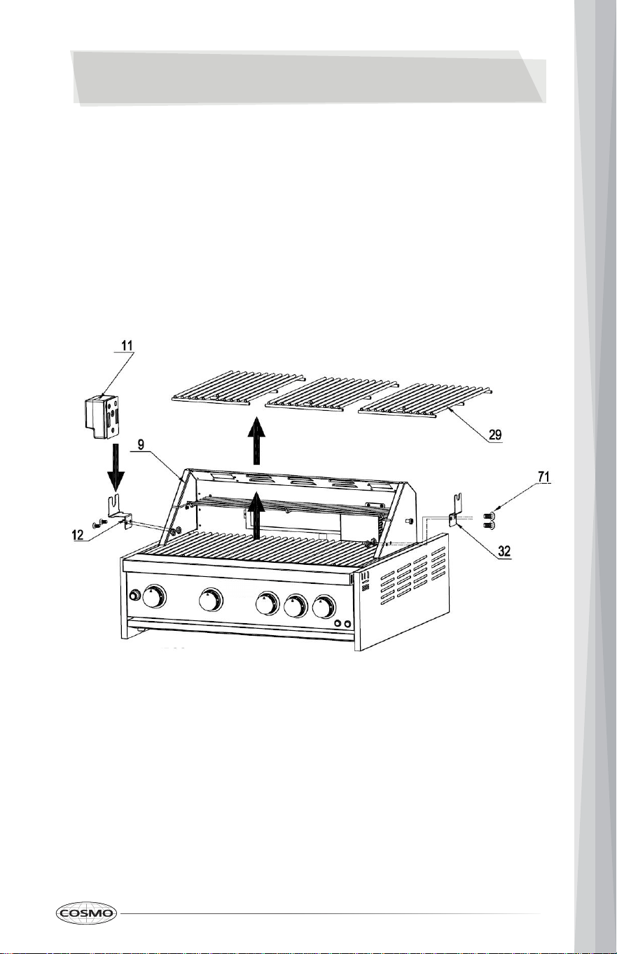
Step 1
1. Open the Grill cover. Remove All 3 pcs cooking racks (Part # 29) for the main
burners to avoid potential damage;
2. Use 2 pcs 1/4“*14 Philips thumb head screw (Part #71) with anti-slip design
(Part #71) to install motor holder (Part #12) to Grill cavity (Part #9);
3. Use 2 pcs 1/4“*14 Philips thumb head screw (Part #71) to install Rotisserie
holder (Part #32) to Grill cavity (Part #9);
4. Put Motor (Part #11) on top of motor support (Part #12) and put back 3 pcs
cooking racks (Part #29)
23
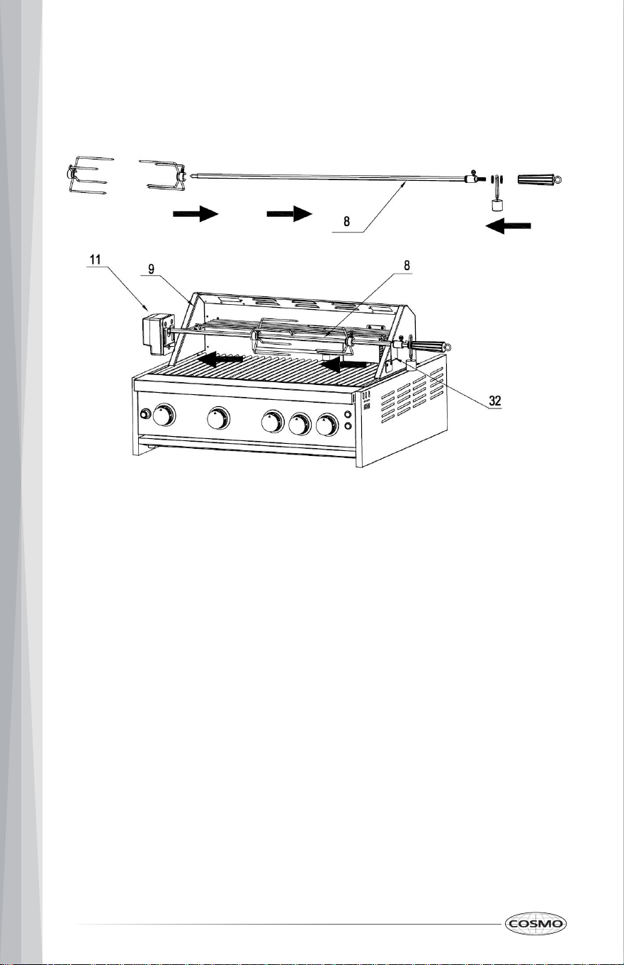
Step 2
1. Put Motor (Part #11) on top of motor support (Part #12) and insert sharp side
of Rotisserie (Part #8) to motor (Part #11), and the other side on top of
Rotisserie holder (Part # 32)
24
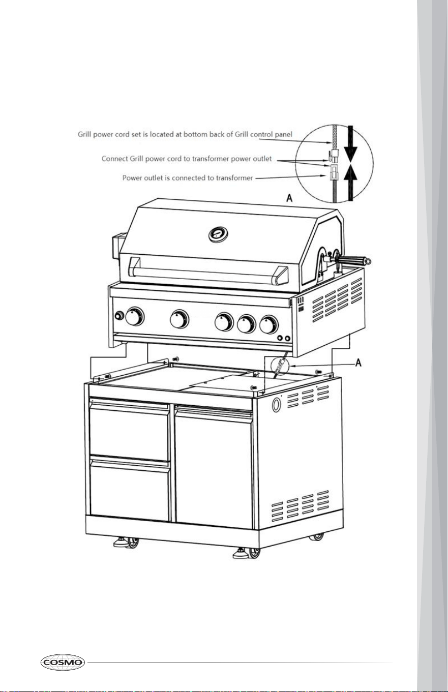
Step 3
1. Use 2 pcs 1/4“*14 Philips thumb head screw with anti-slip design (Part #71) to
Connect Grill body with Cabinet body (For Gas Leak Test, please refer to
Use Manual)
25
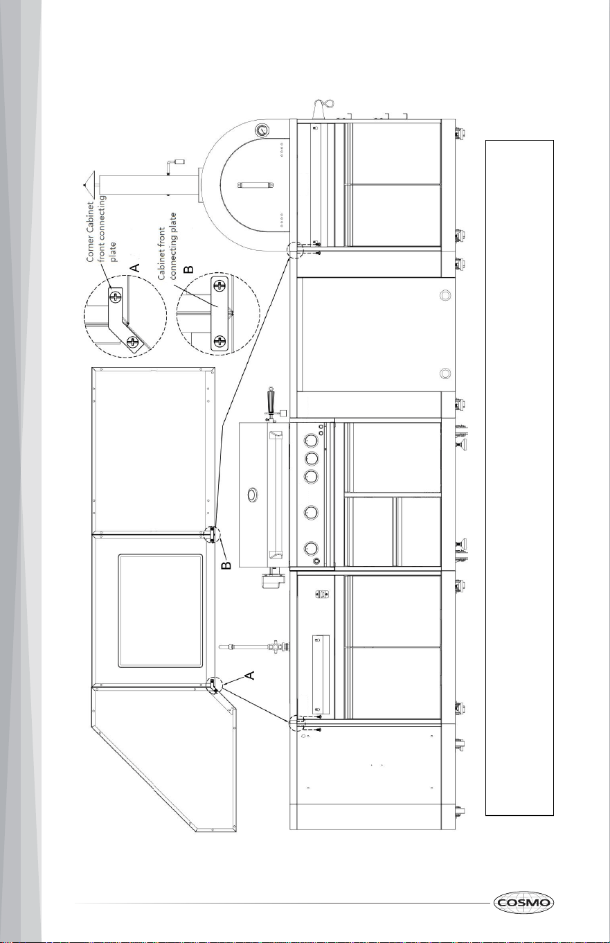
Your Cosmo Outdoor Cabinet could be connected with any other Cosmo Outdoor Cabinet models.
If you are having a Corner Cabinet and you would like to connect it to another cabinet, use corner cabinet connecting plate with 2 pcs 1/4" screws (Part#
06.02.00093-000-A0) to connect both cabinets;
If you are having a Sink Cabinet, Appliance Cabinet or Pizza Oven Cabinet, use cabinet connecting plate with 2 pcs 1/4" screws to connect both cabinets.
26
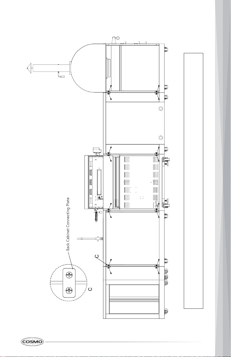
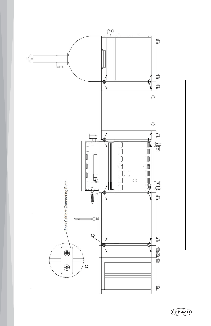
Your Cosmo Outdoor Cabinet could be connected with any other Cosmo Outdoor Cabinet models.
For Back Panel Connections, use Back Cabinet connecting plate with 2 pcs 1/4" screws (Part# 06.02.00093-000-A0) to connect both Cabinets.
27
Your Cosmo Outdoor Cabinet could be connected with any other Cosmo Outdoor Cabinet models.
For Back Panel Connections, use Back Cabinet connecting plate with 2 pcs 1/4" to connect both Cabinets.
28

LIMITED WARRANTY
WARRANTY AND SERVICE
TO RECEIVE WARRANTY SERVICE, YOUR PRODUCT MUST BE REGISTERED.
TO REGISTER AND REVIEW FULL WARRANTY DETAILS, VISIT:
WWW.COSMOAPPLIANCES.COM/WARRANTY
SCAN TO REGISTER
CUSTOMER SUPPORT
TO CHAT WITH US LIVE FOR ASSISTANCE, VISIT:
WWW.COSMOAPPLIANCES.COM/CHAT
SCAN TO CHAT
29
Correct disposal of this product:
This marking indicates that this appliance should not be
disposed with other household wastes. To prevent
possible harm to the environment or human health from
uncontrolled waste disposal, recycle it responsibly to
promote the sustainable reuse of material resources.
IMPORTANT
Do Not Return This Product To The Store
If you have a problem with this product, please contact COSMO Customer
Support at
+1 (888) 784-3108
DATED PROOF OF PURCHASE, MODEL #, AND SERIAL # REQUIRED FOR
WARRANTY SERVICE.
IMPORTANT
Ne pas Réexpédier ce Produit au Magasin
Pour tout problème concernant ce produit, veuillez contacter le service des
consommateurs Cosmo Customer Support au
+1 (888) 784-3108
UNE PREUVE D’ACHAT DATEE EST REQUISE POUR BENEFICIER DE LA GARANTIE.
IMPORTANTE
No regrese este producto a la tienda
Si tiene algún problema con este producto, por favor contacte el ayuda al
cliente COSMO al
+1 (888) 784-3108
(Válido solo en E.U.A.)
NECESITA UNA PRUEBA DE DE COMPRA FECHADA, NÚMERO DE MODELO Y DE
SERIE PARA EL SERVICIO DE LA GARANTÍA.
30

MEMO
31

Cosmo is constantly making efforts to improve the quality and
performance of our products, so we may make changes to our
appliances without updating this manual.
Electronic version of this manual is available at:
www.cosmoappliances.com