
The installation of this product must be made by a qualified professional.

11 • Load config.
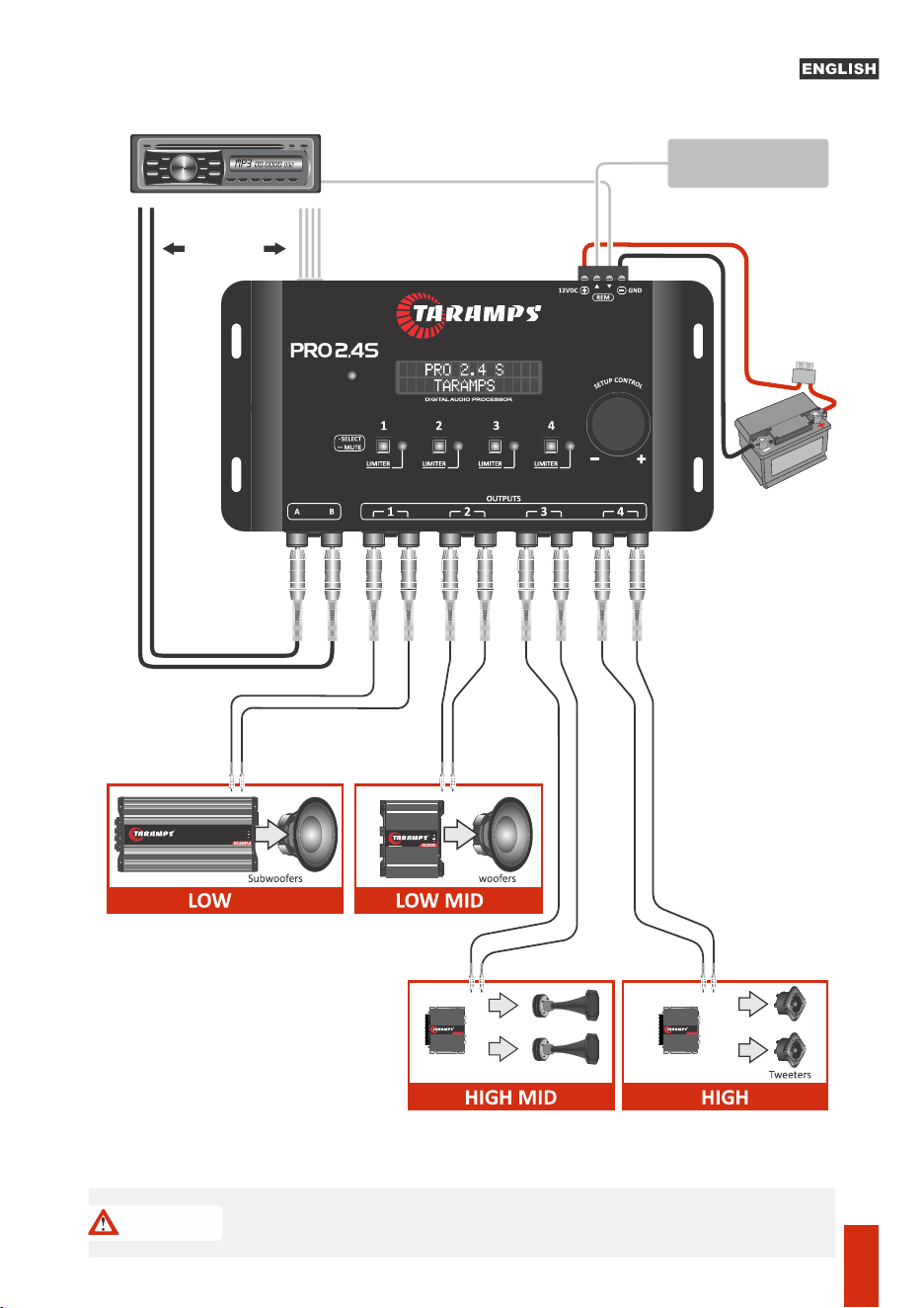
12 • Connecng processor inputs and outputs
10 •Audio generator
08 •Fhase
•Eq. parameter. output
•How to set the alignment parameter value
09 •Outputs level
• Save Config.
• Password / lock
• Language
• Presets EQ
13 • Technical Features
07 •Alignment (delay)
• Limiter
• Text Message
01 • Term of Warranty
• Technical assistance
• Audio menu
04 • Navigang through menus and
parameters
• Crossover
• Geng to know screens and basic
operaons
05 • Menu structures and description
06 • Input Graphic Equalizer
• Important recommendaons
• Input/output routing
• Input parametric equalizer
02 • Introducon
• Safety
03 • Processor Overview
• Safety requirements
Index
Term of warranty
Technical assistance
For international support, check on our website:
www.taramps.com.br/en/rede-de-assistencias-tecnicas or contact direct the factory support:
Phones: +55 18 3266-4050 / +55 18 99749-3391
E-mail: [email protected]om.br
This warranty excludes:
•Tamper or torn warranty seal;
•Defects caused by accessories, modifications or features attached to the product;
•Cases in which the product is not used in adequate conditions;
•Warranty card is not properly filled or torn;
•Costs involving uninstallation, reinstallation of equipment as well as shipment to the factory;
•Damaged products by improper installation, water infiltration, violation by unauthorized individuals;
•The product with damage from falling, bumps or nature related problems (flooding, lightning, etc.);
TARAMPS, located on Abilio Daguano Street 274, Res. Manoel Martins – Alfredo Marcondes, SP - Brazil,
ZIP CODE 19180-000, guarantees this product against any defects on terms of project, making, assembling,
and/or with solidarity, due to project vices which cause it improper or inadequate to its original use within
12 months from the date of purchase. In case of defect during the warranty period, TARAMPS responsibility
is limited to the repairing or substitution of the device of its own making.
•Damage of any kind, due to problems in the product, as well as losses caused by discontinued use of the
product.
01
Safety requirements
Introduction
Taramps reserves the right to modify the contents of this document at any me without prior noce and does not
have the obligaon to apply the changes in units which were previously produced.
To ensure proper use, please read through this manual before using the processor. It is specially
important that you know the WARNINGS and CAUTIONS contained here.
- Use the correct tools for installing this product.
- Never install the product in places exposed to dust, humidity and water. Pay attention to install
it far from fuel tank, fuel lines, heat sources and other parts of vehicle.
- Be sure to install protection fuse or a circuit braker near to battery. Follow the ampere rating as
indicated here in this manual. Use of improper fuse or circuit breaker could result in overheat,
smoke, damage to product, injury or burns.
- Avoid running wires over or through sharp edges. Use rubber or plastic grommets to protect
any wires routed through car's body.
- Automotive sound systems may produce high sound pressure levels. Avoid continuous
exposure to levels over 85dB to prevent permanent hearing loss.
- The installation of this product must be done by a qualified professional.
- This product is for use with 12V batteries. Always check the voltage before installing.
As you read this manual, pay attention to the safety symbols.
Safety
This symbol with “CAUTION” is intended to alert the user to the presence of
important instructions. Failure to heed the instructions will result in risk of injury
to user or product damage.
CAUTION
Read this manual before installing the product. In case of
questions contact our technical support:
+55 (18) 3266-4050 or www.taramps.com.br.
At the end of its lifespan, this product must not be disposed of in household waste.
Look for an electronic equipment collection or recycling center for proper disposal.
02
3 - Remote ouput: For connection in amplifiers
The wire gauge for power supply connections is 1,5mm² (15 AWG) for positive and negative wires,
and 0,50mm² (20 AWG) for remote signal wire.
1 - Power supply negative: Connect to negative pole of battery.
4 - Powe supply positive: Connect to positive pole (12V) of battery.
2 - Remote signal input: Connect to remote signal output from head unit.
For protection against overload, install a fuse on positive wire, close to battery terminal (1A). See
page 12.
Key recommendations
Declaration of Conformity
Hereby, Taramps Electronics Ltda declares that the product
PRO 2.4S complies with the Directive 2014/30/EU, according
with the following harmonized standard:
-EN 50498:2010
The full text of the EU Declaration of Conformity is available at
the Product Page on Internet.
TARAMPS ELECTRONICS LTDA
Alfredo Marcondes - SP
Brazil
Electromagnetic compatibility (EMC) -
Product family standard for aftermarket
electronic equipment in vehicles
Note: The system is designed for use in virtually all mulmedia head units on the market.
However, on some head units , you may not get the trigger effect due to the type of audio output
circuit. In this case, use the REMOTE wire for triggering it normally.
Limiter / clip LEDs: They have a dual funcon: They indicate that the signal from that output has
reached the maximum level (when the limiter is off) or the actuaon of the limiter (when the
signal reaches the threshold defined in the limiter).
It features funcon of triggering through the input signal, so it eliminates the use of the
REMOTE IN wire from the power connector when using this input.
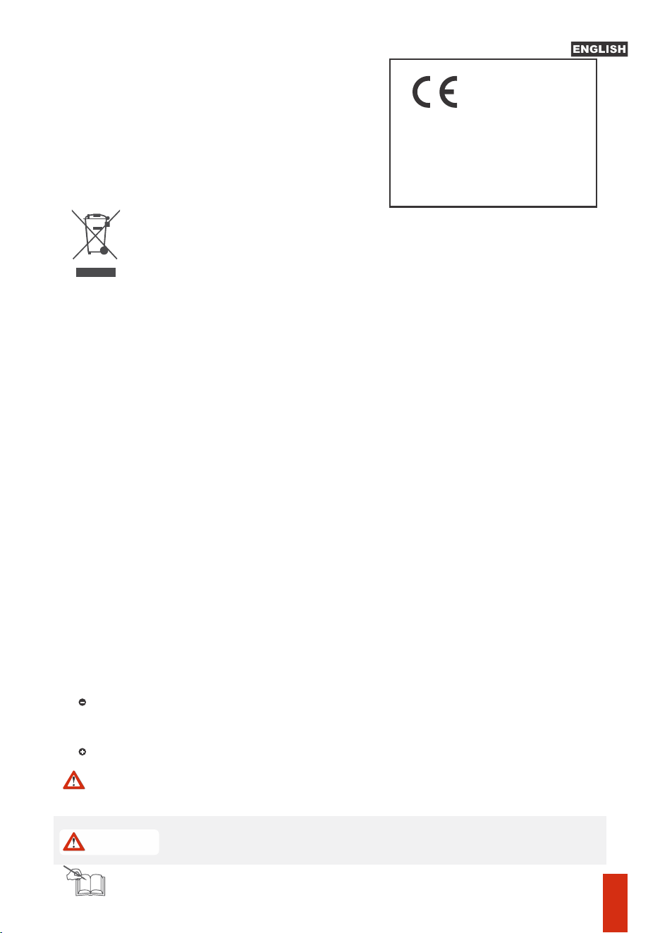
Power connector: See page 12.
Input clip indicator LED: It shows that the signal is reaching the maximum limit of the processor
input, which causes signal distoron. If it comes on, reduce the volume of the signal source and
readjust the system gains accordingly.
RCA signals input: Input for low level / high impedance (RCA) signals.
WIRE High Level Input: Input for high level / low impedance signals (from the speaker output of
the players or mulmedia center).
INPUTS
INPUT
CLIP
Automac Remote
HIGH LEVEL IN
A
B
+
-
+
-
OUT IN
OUT CLIP OUT CLIP OUT CLIP OUT CLIP
Rotary
encoder
LCD Display
Signal Input
(A & B)
Input clip
LED indicator
LED indicators
limiter and clip and
output
High Level input
(B and A)
Power supply
connectors
Select / Mute
keys
Signal output ways 1 ~ 4
PRO 2.4 S
TARAMPS
Idioma/language
>PORTUGUES
INITIAL SETUP: When turned on for the first me, the
processor waits for the language to be set. Choose the
desired language and confirm with a quick touch in the center
of the encoder.
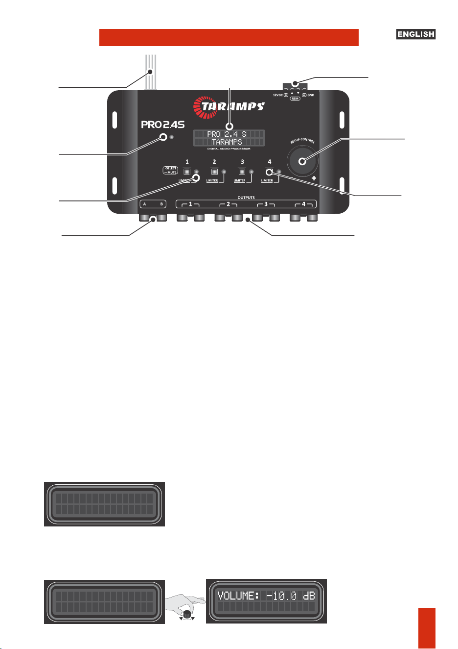
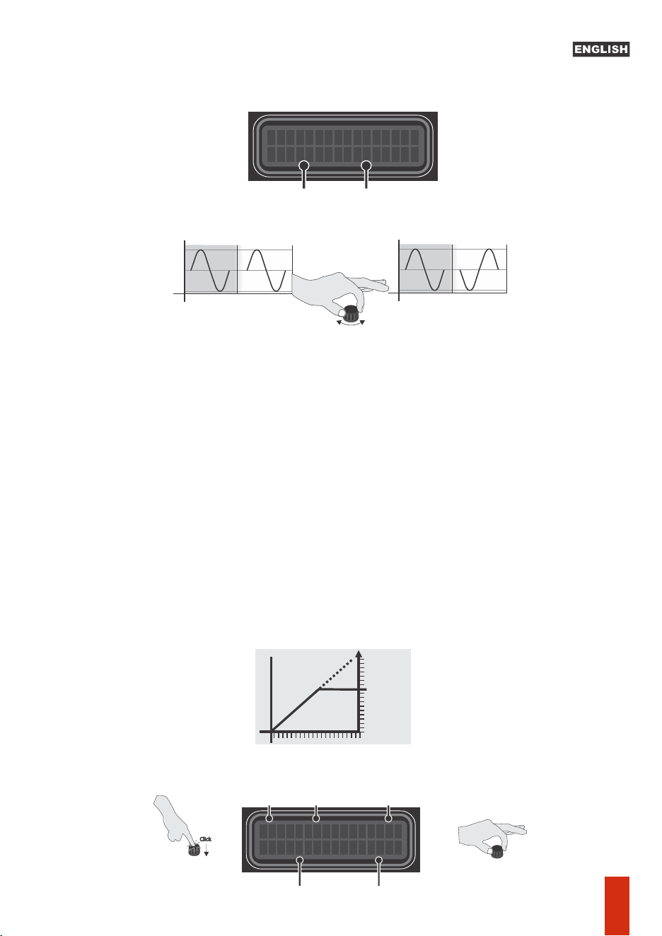
Screens & basic operation:
Turning the encoder knob (clockwise or counterclockwise), adjusts the master volume (Input
volume).
Processor overview
03
MAIN MENU
Audio Generator
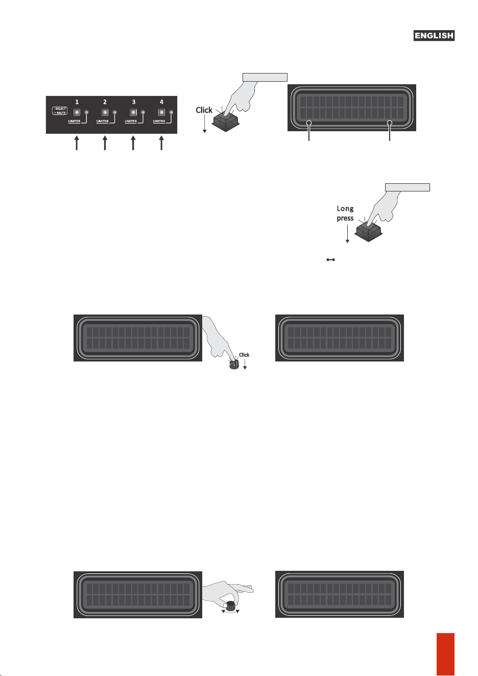
Output selection keys
Click
MAIN MENU
Audio
Quick touch (Click) on the key of each output(1 to 4) It performs an adjustment of the individual
gain in each output.
to the inial screen.
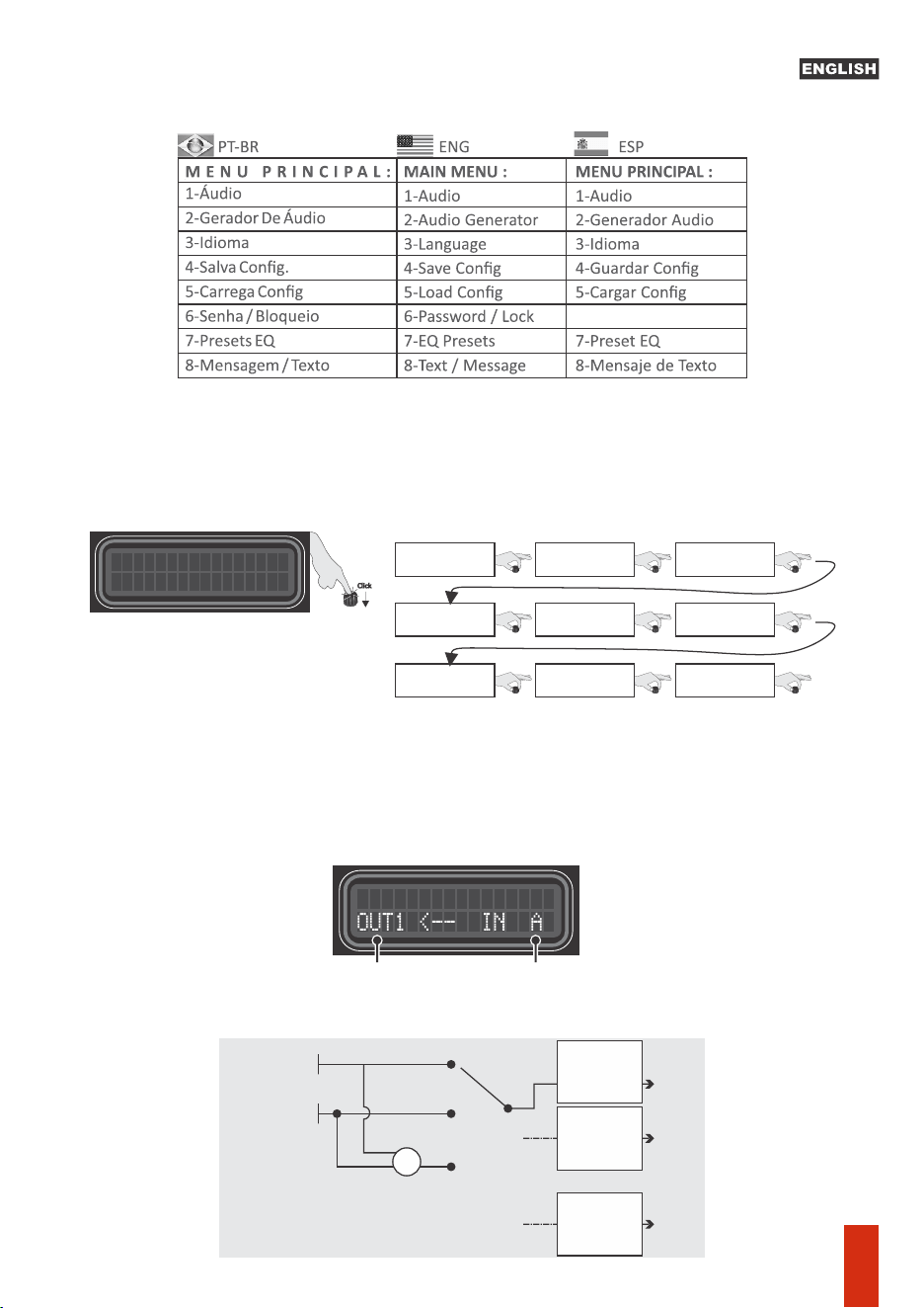
Quick click on the center of the encoder, to access the MAIN MENU and its funcons.
Long touch (1 second) in the center of the encoder returns to the previous menu, unl returning
Use the encoder, turning le (decrement) or right (increment). Menu selecon, opon or
parameter change can be done by pressing the center of the encoder.
Tip: To fine-tune a parameter or increment/decrement the number aer the decimal point,
rotate the encoder slowly. E.g., in the signal level (dB) adjustments, the increment will be 0.1dB
when turning the encoder slowly, and 1dB when turning it more connuously and quickly.
Note: In any of the audio adjustment screens, the hotkeys for channels 1 to 4 allow you to check
and adjust the parameters of each channel without leaving the desired opon
Individual mute: Press the output key (1 to 4) for 1 second unl
the key goes out. To unmute individual sound , press it again for
1 second.
Long
press
OUT 1 a OUT 4
1 second
MUTE
OUT 1 a OUT 4
• SELECT
OUT CLIP OUT CLIP OUT CLIP OUT CLIP
MAIN MENU
Audio
PRO 2.4 S
TARAMPS
Click
OUTPUTS LEVEL
OUT1
:
0.0dB
Output levelSelected
Output
Menu & parameters navigation
04
Click
mAIN MENU
Audio
I/O Roung: Defines the internal connecons between outputs and inputs. Available opons:
A, B or A+B (sum of the two inputs).
E.g.: seng the OUT 1 output to A, its signal will come from input A.
1- Audio menu: Adjusts and controls related to audio processing:
Press the encoder buon (center – long press) to back to Main Screen.
Input A
A
OUT
1
OUT
2
OUT
4
A+B
B
Input B
+
CROSSOVER
ALIGNMENT
PHASE
LIMITER
PARAMETRIC EQ
CROSSOVER
ALIGNMENT
PHASE
LIMITER
PARAMETRIC EQ
CROSSOVER
ALIGNMENT
PHASE
LIMITER
PARAMETRIC EQ
.
.
.
I / O
Roung
Crossover
Limiter
15 Band Equalizer
Delay
Output Level
In Parametric EQ
Phase
Output Param. EQ.
Turn
Turn
Turn
Turn
Turn
Turn
Turn
Turn
Turn
Menu structure & Description
AUDIO ROUTING
Use the OUTx keys to select the
desired way
Turn the rotary encoder
to select the input
6-Contraseña / Bloqueo
05
f: 1000Hz Q:0.4
PEQ IN +0.0 dB
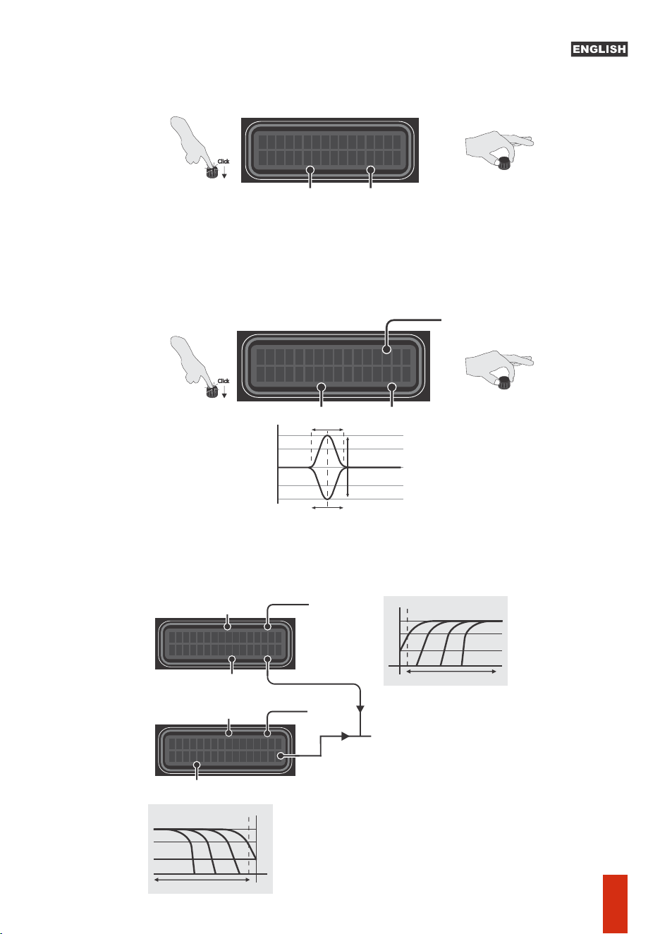
- Input parametric equalizer: EQ with 1 band and adjustable parameters, acts simultaneously
on inputs A and B.
G = Filter gain/aenuaon (-12dB to +12dB)
Q = Filter width adjustment from 0.4 (widest) to 10.0 (narrowest)
F = Filter actuaon center frequency, adjustable from 10Hz to 22KHz
-Band equalizer: It has 15 bands of equalizaon, with aenuaon /boost of up to 12dB, at the
center frequencies defined in the ISO standard (25 to 16KHz, 2/3 octave). Acts simultaneously on
inputs A and B.
The Pro 2.4S has 12 preset equalizers, selectable in MAIN MENU > Presets EQ.
HPF
10Hz
XOVER LPF OUT1
f
:
20000 Hz OFF
Low Pass Frequency
selecon
Selected
output
XOVER HPF OUT1
f
:
2
0 Hz OFF
Selected output
High Pass Frequency
selecon
Cut off Frequency
LPF
22KHz10Hz
Cut off Frequency
Off
Linkwitz - Rilley c/ -12dB/octave
Linkwitz - Rilley c/ -18dB/octave
Linkwitz - Rilley c/ -24dB/octave
Linkwitz - Rilley c/ -36dB/octave
Linkwitz - Rilley c/ -48dB/octave
Buerworth c/ -6dB/octave
Buerworth c/ -12dB/octave
Buerworth c/ -18dB/octave
Buerworth c/ -24dB/octave
Buerworth c/ -36dB/octave
Buerworth c/ -48dB/octave
FILTER TYPE / ATTENUATION:
22KHz
OFF:
LR12
LR18
LR24
LR36
LR48
BT6
BT12
BT18
BT24
BT36
BT48
Gain or Aenuaon
Width (Q)
Central frequency
f: 25Hz +0.0dB
EQ.
GRAFICO
gain or aenuaon
Selected band
Rotate the encoder to change the
selected parameter
Click on the encoder centerto select
the desired parameter
Click
Rotate the encoder to change the
selected parameter
Click on the encoder centerto select
the desired parameter
Click
Q
G+
G-
F
+12dB
-12dB
10Hz 22KHz
0dB
Gain
Aenuaon
-Crossover: Set the high pass (HPF) and low pass (LPF) filters of selected output way. The cutoff
frequencies could be set from 10Hz to 22KHz, and are available some kinds of filters
(Buerworth, Bessel, Linkwitz Rilley) in different slopes (-6, -12, -18, -24, -36 e -48dB/Octave).
06
DELAY ----> OUT1
A
A
A
Rotate the rotary encoder to set the delay amount to be applied.
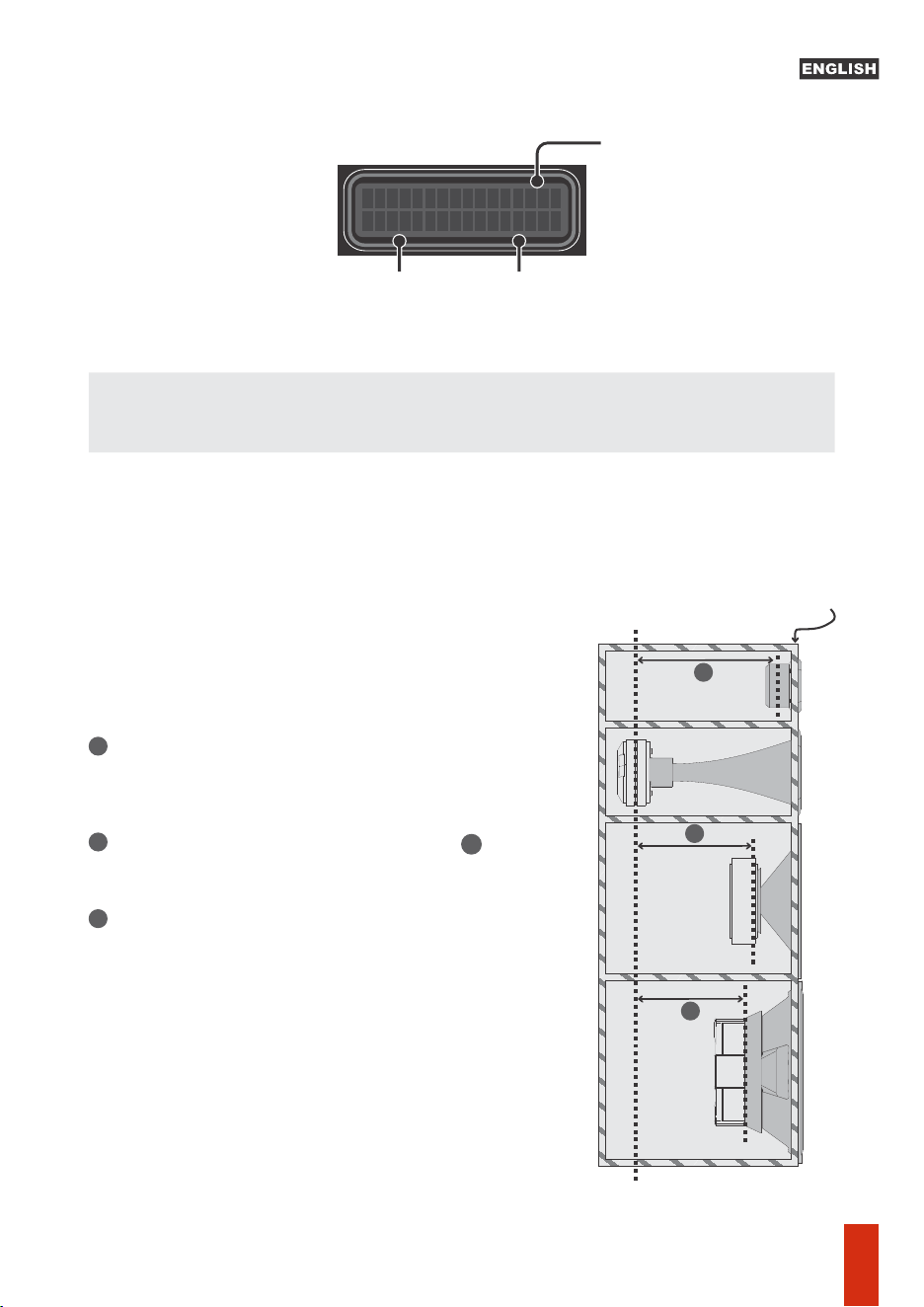
The voice coils of each transducers isn't aligned inside the acoustic box, so there is some delay
that can degrade the perfect audio playing. The Delay feature apply different delay amount for
each output way, in order to get the perfect audio alignment.
Acoustic box front panel
Reference position (*)
Set the reference coil (*) farthest from the box panel (in
our example, the reference was the center of the horn
coil)
Measure the other channels and find the measure . Set
the closest measurement (in cm) for each channel.
Repeat the procedure for the other channels (the
channel selection can be done through the keys of each
channel).
A
1
2
3
Selected Output
Delay me
Distance
Delay: Set the delay to be applied to audio signal, for systems alignment. The posion of
transducer's voice coil should be taken in account in order to set the opmal delay value.
0.0cm 0.000ms
How to set the delay parameter value (centimeter):
07
PHASE CONTROL
OUT1 [
0
] 180
-Phase: Allows inverng the phase of the channel output signal, selecng opon
[180].Select the channel using the OUT1 to OUT4 selecon keys and select the desired phase by
turning the encoder.
Modes: MAN = Manual Aack and Release adjustment; AUT: Sets the Aack and Release
parameters automacally, according to the frequency cutoff (HPF).
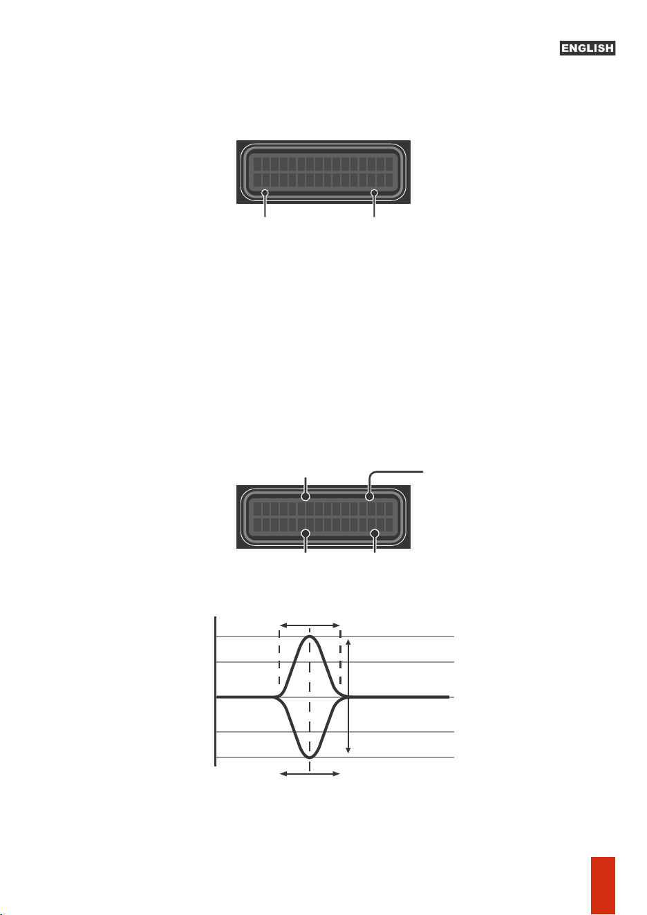
-Limiter: Configures the limiter, which acts as a limiter on the maximum signal level of the
processor output, not to exceed the power limit defined for each channel.
Limiter parameters:
T = Threshold, – Point from which the limiter starts to act (indicated by the lighng of the
RED LED on each channel). To turn off the limiter, turn the encoder clockwise unl [OFF] that
appears at the threshold value.
A = Aack, – Time the limiter waits before reducing gain aer the signal exceeds the
threshold.
R = Release, – Time it takes the limiter to return to its original gain aer the signal drops
below the threshold.
0d
MAN
OUT1 +0 .
B
A:
.0mS
R
16mS
1
:
Threshold
Limiter
mode
Selected output
Release
Aack
Gain
Threshold
Input Output
0° 0° 0°
+
- -
+
Reverse polarity
Input Output
180°
+
-
-
+
0°
180°
Phase
Selected output
Rotate the encoder to change
theselected parameter
Click on the encoder centerto select
the desired parameter
Click
08
-Output parametric EQ.: EQ with 1 band and adjustable parameters for:
G = Filter gain/aenuaon (-12dB to +12dB)
F = Filter actuaon central frequency, adjustable from 10Hz to 22KHz
Q = Filter width adjustment from 0.4 (widest) to 10.0 (narrowest)
Note: This funcon can be accessed outside the menu by simply pressing the corresponding
output key when in the main screen.
OUTPUT LEVEL
OUT1
:
0.0dB
Peq OUT1
+0
.0dB
f: 20Hz
Q
: 0.4
Output levelSelected output
Gain or Aenuaon
Width(Q)
Central Frequency
Selected Output
Q
G+
G-
F
+12dB
-12dB
10Hz 22KHz
0dB
Gain
Aenuaon
-Output level: Set the level for each output way. Allow apply up to +15dB gain or -45dB
aenuaon.
Select the desired way using the OUTx (1-4) Keys.
09
4-) Save config: Allows you to choose the memory locaon and assign a convenient
name to these sengs. Selecng which memory locaon, click on the encoder center
to switch to the text. Rotate the encoder to select the desired leer, click on the center
of the encoder to move to the next character. To erase, rotate the encoder unl “<” +
quick touch on the center of the encoder. To finish eding and save the memory
name, place the cursor aer the last character + long press on the
center of the encoder and confirm “YES”.
variable amplitude. With 4 modes:
- Fixed Frequency: Sine generator with frequency (10Hz to 22KHz) and amplitude
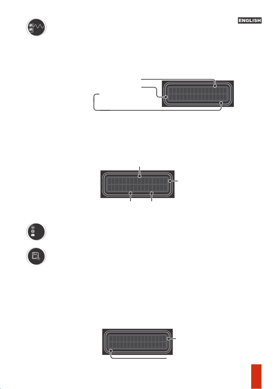
-) Audio Generator: Sine wave generator, with frequency and
(-60dB to 0dB) adjustments. Note that when acvang the generator, the signal is
sent to all outputs and it is possible to adjust the other funcons and parameters in
real me, since the generator remains acve and defined as a signal source when in
the ON posion, even when accessing another funcon. .
--Sweep (Slow / Medium / Fast): It performs a signal sweep, with the inial and final
frequency defined by the user, which remains in a connuous cycle (repeang) unl
the generator is turned OFF. There are 3 sweep speeds avaliable.
Port
Eng
Es p
GENERATOR-45
.
0d
B
f: 1000Hz OFF
Signal level
Frequency
Generator on/off
SWEEP-45
.
0d
B
f: 10->22000Hz
Signal Level
OFF
Final
Frequency
On/ Off
Sweep
Inial
Frequency
_
Memory posion
Customizable name
3-) Language: Choose the desired language (Portuguese, English or Spanish)
10
SAVE
Memory
1
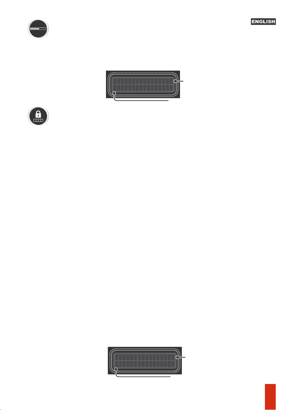
6-) Password / lock: Allows you to lock the processor using a password (the default
password is 1234) or change the password to a personalized one, with 4 digits.
NOTE: When locking the processor, a padlock icon will appear in the upper right
corner of the screen. A password will be required to access the sengs.
To reset the processor to factory sengs without accessing the menu (e.g. due to
lost/forgoen password), just turn on the processor while keeping the keys of ways 1
and 2 and the center of the encoder pressed simultaneously.
This will erase the contents of user sengs memories and reset the product to inial
setup.
8-) Text message: Defines a text of up to 15 alphanumeric characters to be displayed
as screen saver animaon. Enable the funcon by selecng ON and with a quick touch
on the center of the encoder, and go to text eding (blinking cursor). Rotate the
encoder to select the desired leer, click the center of the encoder to move to the next
character. To erase, turn the encoder unl “<” + quick touch on the center of the
encoder. To finish eding and save the text, place the cursor aer the last character +
long press in the center of the encoder. Aer about 3 seconds of no acvity on the
main screen, the text will be displayed as an animaon on the screen.
•BASS BOOST
7-) Presets EQ: The Pro 2.4S has 12 preset equalizers. Select the music style and press
the encoder center to apply the equalizaon curve:
•LOUDNESS
•FLAT
•MID-BASS BOOST
•TREBLE BOOST
•POWERFUL
****
5-) Load config: Load a previously saved configuraon or the factory default
seng. Rotate the encoder to select the desired memory, click on the center of the
encoder to select and then confirm. Important: when you select the FACTORY
SETTINGS opon, the previously saved sengs will be lost.
MEMORY 1 ORIGIN
_
Memory posion
Previously saved name
TEXT:
ON
_
Enables (ON) / Disables (OFF)
the text message display
Custom Name
•ELECTRONIC
•ROCK STYLE
•HIP-HOP STYLE
•POP MUSIC
•VOCAL
•COMPETITION
11
TS 400X4
AMPLIFIER 400WATTS - 2 OHMS
1A
Head Units
RCA output
or
Wires cable
Compression driver
Connecting Processor Inputs and Outputs
TS 400X4
AMPLIFIER 400WATTS - 2 OHMS
INPUTS
INPUT
CLIP
Automac Remote
HIGH LEVEL IN
A
B
+
-
+
-
OUT IN
OUT CLIP OUT CLIP OUT CLIP OUT CLIP
For connecon
in amplifiers
Check power polarity and recommended gauge.
it is recommended to install a 1 Ampere fuse on the positive supply terminal.
*Illustrative images
RCA Cable
Taramps
12
Cable Remote 0,50mm² (20 AWG)
1.5mm² (15 A
WG)
CAUTION

Processing
Sampling rate...................................................................................................48KHz
nputs and Outputs:
Number of input channels.......................................................................................2
Input/output roung:................................................................................. A, B, A+B
General gain adjustment:............................................................................-80 a 0dB
Output gain adjustment:.........................................................................-45 a +15dB
Input impedance (RCA):.............................................................................10K ohms
Number of output channels.....................................................................................4
Input impedance (high level):......................................................................50 ohms
Output impedance...:...................................................................................47 ohms
Maximum input level (RCA):....................................................... 5,9Vpp (2,1V RMS)
Maximum input level (High level):...................... .........................28Vpp (10V RMS)
Resoluon........................................................................................................24bits
Maximum output level:.............................................................. 5,9Vpp (2,1V RMS)
Aenuaon / Gain:............................................................................-12dB to+12dB
Release: ............................................................................................1mS to1600mS
Output parametric EQ:
Frequency response (-1dB)..................................................................10Hz a 22KHz
Signal / Noise Rao:........................................................................................>90dB
Input graphic equalizer, 15 bands, 2/3 octave and 12 presets:
Aack: .............................................................................................0.1mS to 100mS
MUTE Funcon..................................................................Individual at each output
Cutoff frequency: ......................................................... variable from 10Hz to 22KH
Q factor adjustment :....................................................................................0,4 a 10
Total Harmonic Distoron................................................................................0,01%
Buerworth Filters.............................................. -6,-12,-18, -24, -36, -48dB/octave
Languages: ............................................................Portuguese, English and Spanish
Input Parametric EQ:
Linkwitz Rilley Filters.................................................. -12,-18,-24,-36,-48dB/octave
Crossover (HPF e LPF):
Central frequency:........................................................variable from 10Hz to 22KHz
Aenuaon / Gain:.............................................................................-12dB a +12dB
Gain:..........................................................................................................-60 to 0dB
Modes:..................................................................Fixed Frequency / 3 speed sweep
Seng memory posions: ........................Factory default + 3 assignable posions
Q Factor Adjustment....................................................................................0.4 to 10
Threshold:.................................................................................................-24 to 0dB
Audio generator (Sine waveform)
Frequency range...........................................................Variable from 10Hz to 22KHz
Aenuaon / Gain: ...........................................................................-12dB to +12dB
Adjustable Limiter:
Crosstalk (separaon between channels)........................................................>80dB
2.5K,4K,6.3K,10K,16KHz
Frequencies:...............................................25,40,63,100,160,250,400,630,1K,1.6K,
Alignment (Delay):............................................................................8,0mS (272cm)
Fhase:............................................................................................................0 / 180°
Central Frequency: ......................................................variable from 10Hz to 22KHz
Screensaver funcon: ........................................................Text up to 15 characters
Nominal consumpon (12.6V): ................... ............. .....................................0.20A
Dimensions (WxHxD):................................198 x 37 x 113mm (7.80" x 1.46" x 4.45)
Weight:..............................................................................................0.45Kg (0.99lb)
Supply Voltage: .....................................................................................10 to 16VDC
Access protecon: ............................................... 4 password digits (customizable)
Technical features
13

MN_015235_R00
Fabricado por / Manufactured by:
TARAMPS ELECTRONICS LTDA
CNPJ / TAX ID: 11.273.485/0001-03
R. João Silvério, 121 • Res. Manoel Martins
Alfredo Marcondes - SP
Indústria Brasileira - Made in Brazil