
®
Making Good Sound Great
™
Six-Channel Line Output Converter with
Signal Delay, Equalization, and AccuBASS
®
for interfacing with factory installed audio systems
The DQ-61 is your gateway to amazing sound from a factory head unit.
It is a compact six channel, high-performance, line level converter with
independent mul-channel equalizaon and signal delay to custom
tune the system. AudioControl’s patent pending AccuBASS
®
system
corrects for the factory bass roll-o present in so many of today’s cars.
In short; the DQ-61 can make every car sound its very best.
Whether this is your rst product from the rainforest dwellers of
AudioControl, or you are already a rm believer, you will denitely
enjoy how great the DQ-61 can make your performance system sound.

----------------------------------------------- 2 -----------------------------------------------
Important Safety Instructions
1. Read these instructions.
2. Keep these instructions.
3. Heed all warnings.
4. Follow all instructions.
5. Do not use this apparatus near water.
6. Clean only with a dry cloth.
7. Do not block any ventilation openings. Install in accordance with the manu-
facturer’s instructions.
8. Do not install near any heat sources such as muers, silencers, exhaust
pipes, or other apparatus (including ampliers) that produce heat.
9. WARNING: Improper installation may lead to permanent injury or death.
Installation of the apparatus must be done with great care by qualied per-
sonnel, to prevent damage to fuel lines, power, and other electrical wiring,
hydraulic brake lines, and other systems, that might compromise vehicle
safety.
10. Provide +12V and Ground wiring of a suitable thickness/gauge to ensure
adequate current to the apparatus.
11. Use rubber grommets to protect wiring whenever passing wires through
metal openings or bulkheads.
12. Only use attachments/accessories specied by the manufacturer.
13. Refer all servicing to qualied service personnel. Servicing is required when
the apparatus has been damaged in any way, such as the power input ter-
minals are damaged, liquid has been spilled or objects have fallen into the
apparatus, the apparatus has been exposed to rain or moisture, does not
operate normally, or has been dropped.
14. This apparatus shall not be exposed to dripping or splashing, and no object
lled with liquids, shall be placed on the apparatus.
15. Fuses shall be replaced only with the correct type and fuse value, and only
when the apparatus is powered o.
16. Exposure to high sound pressure levels may lead to permanent hearing
loss. Take every precaution to protect your hearing.
----------------------------------------------- 3 -----------------------------------------------
The lightning ash with arrowhead symbol within an equilateral trian-
gle is intended to alert the user to the presence of uninsulated “danger-
ous voltage” within the product’s enclosure, that may be of sucient
magnitude to constitute a risk of electric shock to persons.
The exclamation point within an equilateral triangle is intended to alert
the user of the presence of important operating and maintenance (ser-
vicing) instructions in the literature accompanying the appliance.
Caution: to reduce the risk of electric shock, do not
disassemble the apparatus, other than to remove
the top panel to access the controls. There are no
user-serviceable parts inside. Refer servicing to
qualied personnel.
Recycling notice: If the time comes and this apparatus has fullled its
destiny, do not throw it out into the trash. It has to be carefully recy-
cled for the good of mankind, by a facility specially equipped for the
safe recycling of electronic apparatii. Please contact your local or state
recycling leaders for assistance in locating a suitable nearby recycling
facility. Or, contact us and we might be able to repair it for you.

----------------------------------------------- 4 -----------------------------------------------
Key Features
• User friendly Signal Delay to control the acouscal alignment
between the le and right channels plus the front and subwoofer
channels
• Individual equalizaon controls for the front, rear and subwoofer
channels for simple yet precise system tuning
• Six channels of acve speaker level inputs – accept up to 400
was per channel
• AccuBASS®- AudioControl’s patented processing to correct the
bass roll-o in factory source units
• ACR-3 Dash Control Remote allows for control of the subwoofer
level, to bypass processing, and to setup the delay
• Internal Channel Summing – Easy interface with factory installed
ampliers with built-in crossovers
• Discrete Input and Output level controls
• GTO™ signal sensing inputs (selectable) to turn the DQ-61 on
automacally and give you a 12 volt trigger to turn on your am-
plier
• Bulletproof 5 year warranty (when installed by an authorized
AudioControl dealer)

----------------------------------------------- 5 -----------------------------------------------
Quick Installation Information
If you are a seasoned audio enthusiast and are chomping at the bit
to begin your experience with the DQ-61, we oer some Quick Install
Guidelines below to help maximize your experience. Please also refer
to the system diagrams on page 14, 15, and 16.
1. Physically mount the DQ-61 in a locaon that keeps it away from
beverage spills, food crumbs, and the curious ngers of carnival
folk. You will want to select a locaon that allows you access to
the top panel controls. In many cases you can nd factory speak-
er leads in the rear of the vehicle or at the factory amplier that
are easy to access.
2. The DQ-61 needs to be installed in the signal path between your
OEM source unit (or factory amplier) and an aer-market ampli-
er and/or processor(s). Do not connect the DQ-61 between the
factory head unit and the factory amplier. Locate the amplied
speaker wires that are coming from your factory source unit and/
or amplier and connect them to the speaker-level inputs on
your DQ-61.
Note: If your source unit has front, rear, and subwoofer
speaker-level outputs, connect them to the three sets of inputs
on your DQ-61. If the source unit only has front and rear outputs,
the Auto Mode circuitry in your DQ-61 automacally routes the
Channel 2 input channels to the (Channel 3) subwoofer channels.
3. Use RCA connecng cables to connect the RCA outputs of the
DQ-61 to your aer market amplier(s). If this is not obvious to
you, quickly pack up your DQ-61 and run to your nearest autho-
rized AudioControl dealer to have them perform the installaon.
You will thank us later.

----------------------------------------------- 6 -----------------------------------------------
4. Connect +12 volt power, ground and turn-on wires as needed.
Don’t forget the fuse! Note: The DQ-61 has a 12-volt trigger input
but normally you will just let the GTO turn on circuit take care of
that by itself.
5. Connect your amplier trigger input to the 12-volt trigger output
of the DQ-61
6. Turn your amp gains fully down before turning on the system.
7. Turn on the system and level match your DQ-61 to your source
unit and ampliers.
8. On the chassis of the DQ-61, set Signal Delay Mode to Set-Up.
9. Using the ACR-3 Dash Control, adjust the signal delay between
the Le and Right channels for opmum sound. Check out our
YouTube video for assistance.
11. Tap the ACR-3 Dash Control and adjust the signal delay between
the front and subwoofer outputs.
12. On the chassis, change Signal Delay Mode to Normal.
13. Set the equalizaon controls for the front, rear, and subwoofer
channels. While your ears are a good reference point, we recom-
mend using an audio analyzer whenever possible.
14. Adjust the AccuBASS® seng for maximum bass.
15. Sit back and enjoy the sound
If you have made it to this point and you don’t have any quesons,
then “Congratulaons”! With that said, we certainly encourage you to
set aside some me to grab a beverage or two, and read through this
enre manual, since there is a tremendous amount of useful informa-
on. Plus it would make the technical writer’s mom proud of her boy.
We now interrupt your reading of this manual to highlight a very
important feature of all AudioControl Autosound products…

----------------------------------------------- 7 -----------------------------------------------
Our Bulletproof Warranty
AudioControl Autosound products
are designed and assembled at our
factory in the Pacic Northwest,
just outside of a lile town called
Seale, Washington. By nature,
our products are rather sophis-
cated so we spend a good deal of
me training our dealers and their
installaon team. We do this so you will get the best possible results
from your AudioControl components.
To reinforce this point, if you have an Authorized AudioControl
dealer install your DQ61, we will extend the normal one-year war-
ranty to a full FIVE years parts and labor. Complete details of this
warranty are listed at the end of this manual and on our website at
www.audiocontrol.com.
We now return you to your regularly scheduled reading.
----------------------------------------------- 8 -----------------------------------------------
3
2
4 5
12
15
14
10
11
9 8 7 6
1 13

----------------------------------------------- 9 -----------------------------------------------
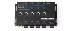
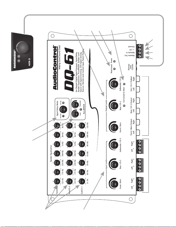
A Guided Tour of the DQ-61
1. Speaker-level Inputs: The DQ-61 has six speaker-level inputs.
These inputs get their signals from the speaker-level outputs
of your factory-installed source unit or amplier. If your source
unit has front, rear, and subwoofer signals, connect them to the
corresponding inputs on your DQ-61. If your source unit only
has front and rear signals, the AutoMode circuitry of the DQ-61
will route the Channel 2 signals to the Channel 3 (subwoofer)
outputs.
2. Input Level Controls: The DQ-61 is capable of receiving high
waage signals from factory installed source units and/or ampli-
ers. The input level controls allow you to adjust the input signal
levels for maximum audio performance of the DQ-61.
3. EqualizaonControls: To custom tune your system, the DQ-61
gives you dedicated equalizaon controls for the Front, Rear, and
Subwoofer outputs. See the secon on Equalizaon Opmiza-
on, page 20 for more details on how to set these for opmum
performance.
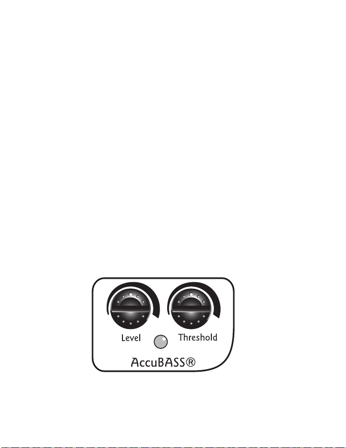
4. AccuBASS®Sengs:This patent pending circuit compensates for
the bass roll-o characteriscs of many factory installed source
units. The Threshold and Level controls let you determine when
the AccuBASS® circuit engages and what level of correcon to
apply. See page 26 for more informaon.
5. SignalDelayMode:This allows the user to put the DQ-61 into a
Set-Up mode and adjust the signal delay sengs using the dash
control. Turn knob to the right unl the Set-Up LED comes on.
When done, turn knob to the le, Normal seng for regular
music listening.

-----------------------------------------------10 ----------------------------------------------
6. Ground: Connect to a good, veried chassis ground (the baery
comes to mind.) Warning:Factory ground wires typically have
mulple devices connected to them so it is not recommended to
use them.
7. +12V Power: Connect to a good source of 12-volt power (the bat-
tery comes to mind)
8. Remote In: In some unusual installaons, you may not want to
use the GTO™ to turn on your system due to secondary funcons
with factory installed source unit. For these cases the DQ-61 can
be turned on remotely with a +12-volt trigger.
9. Remote Out: This outputs 12 volts with 1 amp of current when
the DQ-61 is powered up, so you can turn on external devices
like signal processors and ampliers with this wire.
10. MaximizedIndicator:This brightly colored LED indicates when
the signal level coming into your DQ-61 is just below clipping.
When properly level matched, this LED should icker occasionally
when your system is playing at its maximum volume level.
11. Power: If you have connected all of your power wires correctly,
this LED should be bright red when your system turns on.
12. RemoteLevelControlACR-3(Included):In the Set-Up mode this
control allows for seng the signal delays. In the Normal mode,
it gives control over the Subwoofer/Ch3 level output. Addion-
ally, in the Normal mode, when you tap this switch it will bypass
the equalizaon, signal delay , and AccuBASS® processing of your
DQ-61 so you can compare the sound.
13. Pre-Amp Outputs: These RCA plugs should be connected to the
next component aer the DQ-61, such as a crossover or ampli-
er. Do not connect any speakers directly to your DQ-61. (De-
nitely don’t connect to any home appliances, like your blender or
toaster.)

-----------------------------------------------11 ----------------------------------------------
14. Output Level Controls: These knobs allow you to adjust the
signal level from your source unit to match the input of your
aer-market ampliers.
15. ChannelSummedIndicators:These green (like our grass) LED
indicators let you know which channels are being summed into
the main inputs. Under the cover of your DQ-61 are jumpers that
will allow you to sum selected channels into the main and rear
channels.
-----------------------------------------------12 ----------------------------------------------
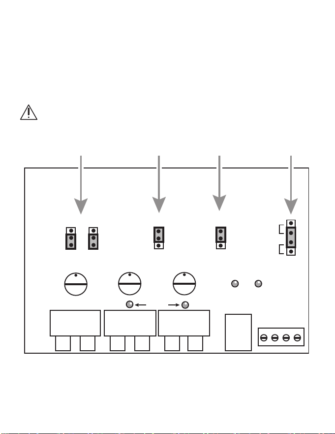
Under the Covers - Internal Jumpers
You can opmize your DQ-61 using most of the controls mounted on
the top of the chassis. However, we recognize there are situaons
where advanced users may have the need to congure the DQ-61 for
specic applicaons. Therefore we have provided a few seng that are
located under the chassis top for limited access.
WARNING: Disconnect power to the DQ-61 before the chassis top
is removed.
1 2 4
DQ-61
Jumper locations
(*shown in factory
positions)
Summing
AutoMode GTO
Signal Sense
Ground
Isolation
Rear
Sum
OFF
Sum
OFF
ON
OFF
Engage
OFF
GND
Isolated
200
PwrMax
Sub
Line
Outputs
Remote
Volume
Summing
LEDs
Power
Inputs
3

-----------------------------------------------13 ----------------------------------------------
1. OutputSummingJumpers:Some factory installed audio systems
include separate ampliers that output limited bandwidth signals
that are acvely crossed over and are connected directly to
tweeters, midranges, and/or woofers. For opmum performance
you will want to combine (or sum) these separate signals into a
single full range signal. The DQ-61 facilitates this internally via
simple jumper sengs that allow you to select which input sig-
nals will be summed into the Front/Main outputs. An addional
feature is that once you move the Summing jumpers to SUM, the
audio signal coming from the Main Output will also come out of
the Channel 2 Output. When the jumper is moved to the “SUM”
posion for a selected channel, the corresponding indicator LED
on the front of the DQ-61 will turn green The shipped-from-the-
factory seng is in the OFF or non-summed posion.
2. AutoMode:Some cars have low-level or other unusual signals
on their speaker leads that may not trigger the AutoMode circuit
and result in signal switching. If this occurs you can move the
internal AutoMode jumper to “OFF”.
3. GTO™SignalSense:In some situaons, factory installed audio
systems may turn ON or “wake up” due to convenience features
like doors chimes, alarms, and cell phone signals triggering the
source. To prevent these from turning your audio system on
unexpectedly, you can bypass the GTO™ circuit by moving the
GTO™ jumper to “OFF,” and use a switched 12-volt signal con-
nected to the Remote In terminal instead. The DQ-61 ships the
GTO in the “ENGAGE” posion.
4. GroundIsolaonSelector:Alternator noise may appear in a sys-
tem because the source unit and amplier(s) are using dierent
grounding schemes. To help in this situaon, we have provided
alternave grounding connecons. Make sure your system is
turned OFF before you move these jumpers. We ship them in the
isolated posion, which usually gives the best results.
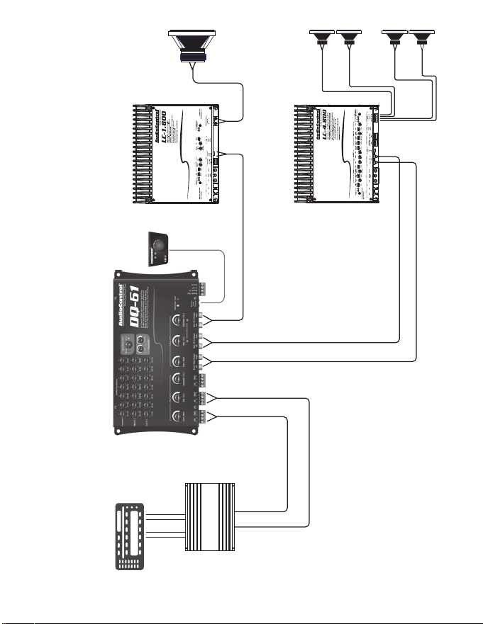
-----------------------------------------------14 ----------------------------------------------
TypicalDQ-61Installaon,usinganAudioControlLC-4.8004-channelamplierandan
LC-1.800SubwooferAmplier
LC-4.800 4-Channel Amplier
Front
Front
Speaker-Level
Speaker-Level
Speaker-Level
Line-Level
Line-Level
Line-Level
Front
L/R
Rear
L/R
Rear
Front L/R
Rear L/R
Subwoofer
Subwoofer
Rear
LC-1.800 Subwoofer Amplier
ACR-3
+
+
+
+
Factory Amplier
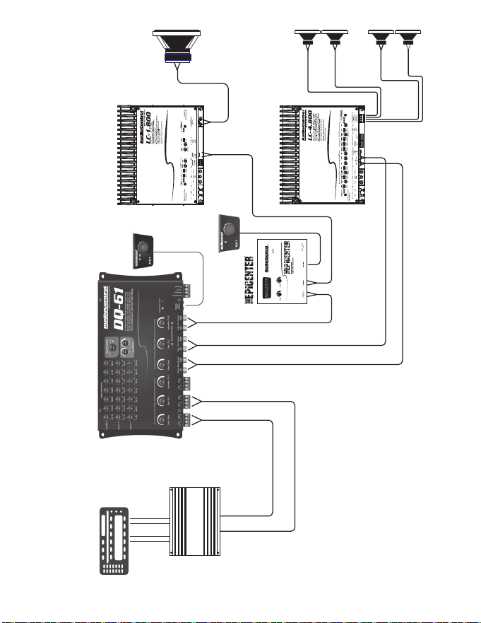
-----------------------------------------------15 ----------------------------------------------
UsingaDQ-61andTheEpicenterandampliersfromAudioControltoachieve
maximumsoundqualityandbass
LC-4.800 4-Channel Amplier
Front
Front
Speaker-Level
Speaker-Level
Speaker-Level
Line-Level
Line-Level
Line-Level
Front
L/R
Rear
L/R
Rear
Front L/R
Rear L/R
Subwoofer
Rear
LC-1.800 Subwoofer Amplier
ACR-3
+
+
+
+
Factory Amplier
Subwoofer
ACR-1
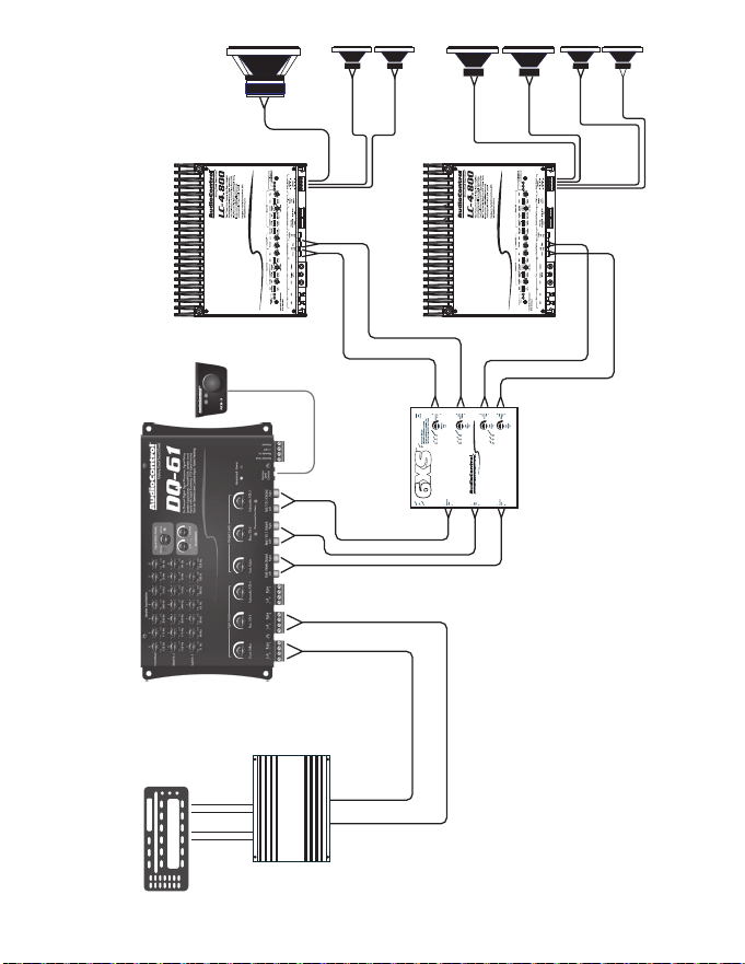
-----------------------------------------------16 ----------------------------------------------
Installaonwitha6XS6-ChannelCrossoverand2LC-4.800ampliers
LC-4.800 4-Channel Amplier
Front
Low-Pass
Front
Rear
Rear L/R
Front
Sub
Sub
Speaker-Level
Mono
Speaker-Level
Speaker-Level
Line-Level
Line-Level
Line-Level
Front
L/R
Rear
L/R
Rear
Front Low-Pass L/R
Front High-Pass L/R
Subwoofer L/R
Rear L/R
Subwoofer
Rear
LC-4.800 4-Channel Amplier
ACR-3
6XS 6-Channel
Crossover
+
+
+
+
Front
High-Pass
+
+
Factory Amplier

-----------------------------------------------17 ----------------------------------------------
Great Features of the DQ-61
SignalDelayOperaon
Because of speaker placement limitaons and the seang posion in a
car, the driver is in an incorrect acousc alignment with the speakers.
The following steps will help you correct the me alignment by delay-
ing the appropriate speakers for just a few milliseconds, so the DQ-61
is able to allow the dierent signals to arrive at the same me, pung
the driver in perfect acouscal alignment.
1. For best performance and ease of set-up, go to our website at
www.audiocontrol.com and download the DQ-61 Set-Up App
for your Apple iPhone or iPad. It’s FREE and will help take all the
guesswork out of seng up the delay. However, if you do not
have access to an iPhone or iPad you can set up the delay just by
using your ears.
2. Aer you have made all your power and ground connecons,
plug in all your inputs and outputs, turn the Signal Delay knob
on the DQ-61 chassis all the way to the right to go into Set-Up
mode. In this mode, the blue LED will blink on the ACR-3 dash
remote. (See the diagrams on the next page.)
3. You will need to make sure that all your delay sengs are set to
zero, using the following procedure: Start with the Le to Right
seng (the Red LED on the ACR-3 remote will be solid) and turn
the ACR-3 knob completely CLOCKWISE unl you no longer hear
any Mute Clicks. Once you have veried your Le to Right is set
to zero, now set your “Sub to Front” delay at zero as follows:
Simply push in the ACR-3 knob to switch from “Le to Right” to
“Sub to Front”. At this me the blue LED will connue to blink
and the red LED will turn o. Again, turn the ACR-3 knob CLOCK-
WISE unl you no longer hear any Mute Clicks. You have now set
all of the delay in the DQ-61 to zero.
-----------------------------------------------18 ----------------------------------------------
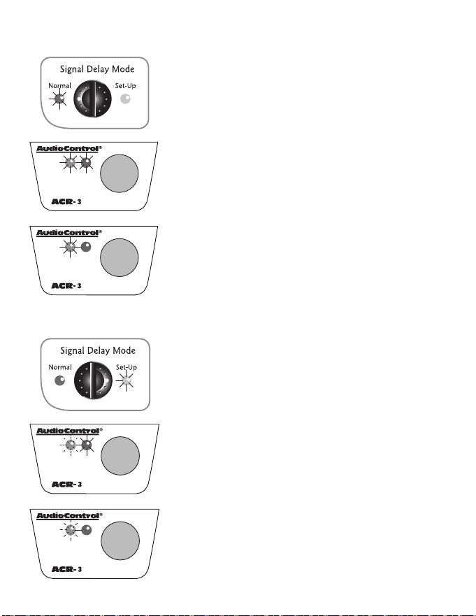
Normal Mode (ACR-3DashKnobControlstheSubOut)
NORMALLEDON
ACR-3 Both LEDs ON
• Signal Delay Engaged
• Equalizer Engaged
• AccuBASS® Engaged
ACR-3BlueLEDOnly
• Signal Delay Disengaged
• Equalizer Disengaged
• AccuBASS® Disengaged
Set-up Mode (DashKnobcontrolstheSignalDelay)
SET-UP LED ON
BlueLEDFlashing,RedLEDSolid
• Signal Delay Adjustment Le to Right
BlueLEDFlashing,RedLEDO
• Signal Delay Adjustment Sub to Front

-----------------------------------------------19 ----------------------------------------------
4. Now you need to carefully choose the source material to listen to
while seng the delay. Choose a song that has very strong vocals
and limited instruments. This will make it much easier to “move”
the image from down at your le knee where it currently exists
to up on the center of the dash where it needs to be.
5. Le/RightDelay: Push on the dash remote unl the blue LED is
blinking and the red LED is solid. With the source material play-
ing, slowly turn the ACR-3 dash control knob COUNTER CLOCK-
WISE. Each detent in the remote represents an amount of me
(in milliseconds) that you are delaying the Le Front Speaker. We
have added a small Mute Click along with the detent on the re-
mote to help you determine your amount of delay. Keep in mind
that if you think you have gone too far you can always start over.
Just turn the knob all the way clockwise to start back at zero and
slowly turn counter clockwise unl you reach your desired result.
6. Front/SubwooferDelay: Once you have dialed in your Le /
Right delay, it’s me to set up the sub. Push on the dash remote
to switch delay modes and verify that the blue LED connues
to blink but the red LED is o. Exactly like you did seng up the
front le speaker, start by slowly turning the knob counter clock-
wise to add delay to both of the front speakers. You will noce
with each Mute Click of the remote, the sub will move forward
toward the driver. Again, if you think you have gone too far or
missed that ‘sweet spot’ you can always start over by just turning
the knob back all the way clockwise and repeat the process
again.
Once you have everything where you want it you are done! Easy right?
Now just go back to the Signal Delay knob on the DQ-61 and turn it
counter clockwise back to Normal mode and you are ready to move to
the next step of set-up.
-----------------------------------------------20 ----------------------------------------------
Equalization Optimization
When it comes to music, everyone has his or her own parcular taste.
Some people want pounding bass and crisp, blood curdling highs. Oth-
ers may prefer a “at” response (whatever the heck that is). At the end
of the day, most people just want their system to sound balanced and
“just like it did in the store” or similar to their buddy’s car. The follow-
ing equalizaon guidelines should help you achieve your own personal
audio nirvana and if you are looking for more detailed informaon on
seng equalizers and small space acouscs please visit the support
secon of our website at www.audiocontrol.com.
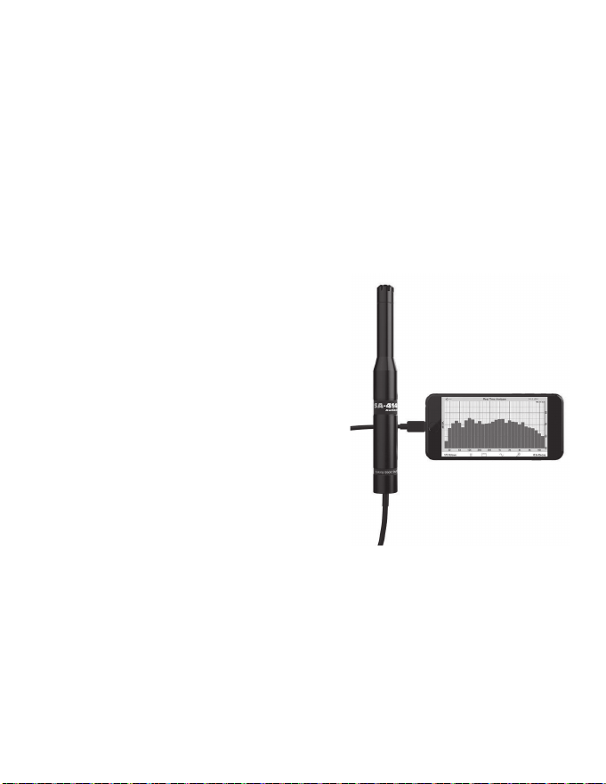
1. For opmum performance, get
your hands on a good quality RTA
(real me analyzer); we happen
to make a really good one: the
SA-4140. If you cannot locate an
RTA, you probably want to have
your authorized AudioControl
dealer perform the equalizaon
adjustments since they will have
one. You can certainly adjust your
DQ-61 using your ears, however,
using an RTA will give you the
best results.
2. Begin playing pink noise through your system and place the mi-
crophone for your analyzer on a microphone stand in the driver’s
seat. Take a careful look at the “curve” on your analyzer and how
one frequency combines with the next. There is no one curve
that will sasfy every person, as we all have dierent tastes. The
key is to use your DQ-61 to help balance your system from one
frequency to the next and give your speakers the sparkle, sizzle,
detail or punch that the acouscs of the car have compromised.

-----------------------------------------------21 ----------------------------------------------
3. Start equalizing by removing or cung any large bumps, peaks,
or areas with too much energy at a parcular frequency. Next,
boost the ranges that do not have enough energy. We strongly
recommend that you cut or decrease energy before you boost.
4. Although the plethora of knobs on your DQ-61 can be inmidat-
ing, fear not as they were designed to give enough control to
maximize your systems performance but not enough to get you
in trouble. Here is an explanaon of the key areas you should
focus on:
Sub-bass:100Hzandbelow–A car without bass is like a day without
sunshine... unless you live where we do because most of the days in
the Pacic Northwest do not have sunshine. This area is one of the
more crical although it is also one of the most dicult to properly
reproduce. Most people prefer their bass frequencies to be 6 to 9 dB
louder than the rest of their system, although there are some crazy
folks that prefer their bass substanally louder. The key in this area is to
have enough speakers and power to produce the amount of bass you
desire but don’t use the controls on the DQ-61 to try and force your
speakers to produce sounds they can’t. Too much bass boost creates a
condion called “speakerus explodus”, which is not prey.
Midbass:100Hzto300Hz– The phrase, “too much of a good thing”
can certainly apply to the midbass frequencies. This is the transion
area of the audio spectrum that is an octave above your sub-bass
frequencies and several octaves below your midrange. Most autosound
systems have too much midbass due to the fact that speakers mounted
in the doors or kick panels cause resonance’s or peaks in the response
curve. These peaks in the midbass can actually mask or block sounds in
the all-important midrange area causing your system to sound dull.

-----------------------------------------------22 ----------------------------------------------
Midrange:300Hzto3kHz– Musical instruments, vocals, mid-range
percussion and many things we associate with imaging and staging
happen in this area of the bandwidth. For that reason you will want to
keep this area as smooth and balanced as possible. Too much boosng
can make you feel like your listening to your system in a le bathroom.
Not enough energy the midrange sounds empty and dry.
Treble:3kHzandUp–If midrange is the cake, then these high or up-
per frequencies are considered the frosng. Many autosound systems
start a gradual decline in this area which is why speaker placement is
very important. The DQ-61 only gives you a few controls in this area
because too much boosng can really make a speaker sound unnatural.
Signal Summing Inputs and Parallel
Outputs
The DQ-61 has the capability to combine together mulple (2, 4, or 6)
input signals from the factory source unit into 2 channels. Some factory
audio systems produce acvely crossed over signals from the ampli-
er feeding signals to the tweeter, midrange, and woofer. The DQ-61
lets you take all of those signals and sum them together to get a high
quality, full range, pre-amp signal. Simply move the summing jumper
for the desired channel into the “On” posion. If the green LED for that
channel is on, you know it is being summed into the main output. Addi-
onally, when you Sum signals together, the signals coming from Front/
Main and Rear/Ch2 are now paralleled providing dual full range signals.
This provides lots of exibility in your system design.
AutoModeInputs:Your DQ-61 is equipped with AudioControl’s unique
AutoMode circuit input that allows for the Rear/Channel 2 input signal
to automacally feed the Sub/Channel 3 outputs, when there is no
signal present on Channel 3. This allows your DQ-61 to accept front and
rear inputs channels and give you three output channels (Front, Rear,
and Sub).

-----------------------------------------------23 ----------------------------------------------
Remote Level Control - ACR-3
The ACR-3 is a mul-funcon remote that
used for making the inial signal delay
adjustments in the Set-Up mode and then
providing level control over the Channel
3/Subwoofer output in the Normal mode.
This allows you to balance the bass level
with the rest of the system and then increase or decrease as needed.
An addional feature of the ACR-3 dash remote is that it allows the sig-
nal processing of the DQ-61 (equalizaon, signal delay, and AccuBASS®)
to be switched in and out of the audio circuit. That means that you can
hear the system with and without the processing and hear the dier-
ence that the tuning makes in the sound of your system.
PlacementandMounng
The ACR-3 dash control may be mounted under the dash using its own
bracket or through a custom hole in the dash. It should be within reach
of the driver and in a spot where the LEDs are plainly visible. Discon-
nect the vehicle baery +12V and Ground connecons before instal-
laon. The dash control mounts with two screws, which aach to the
underside of the dashboard. Slide under the dash and place the dash
control in its mounng posion, mark the two best mounng holes,
carefully drill pilot holes without damaging any under-dash wiring, and
secure with two screws.
-----------------------------------------------24 ----------------------------------------------
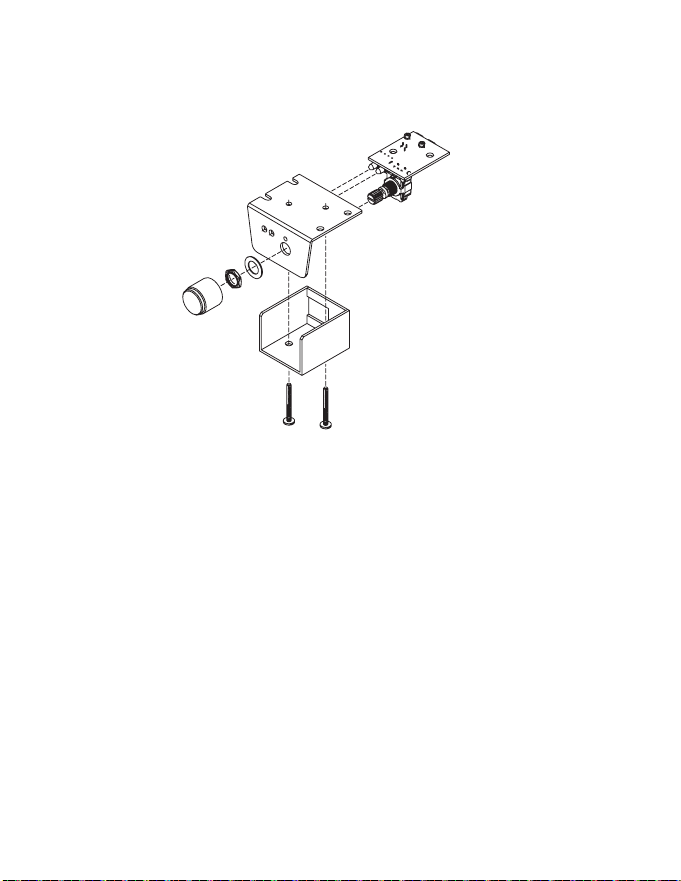
ACR-3CustomInstallaon
For that custom, nished look, the ACR-3 can be ush mounted directly
on the dash-board (or anywhere else).
Disassemble the ACR-3 from its mounng bracket. Drill a 9/32” (7 mm)
hole in the dashboard for the control along with a 3/32” (2.3 mm) hole
for the lock tab and 1/8” (3 mm) holes for the LEDs. Make sure that you
do not drill though any wires or other components. Reassemble the
dash control components on the dashboard.
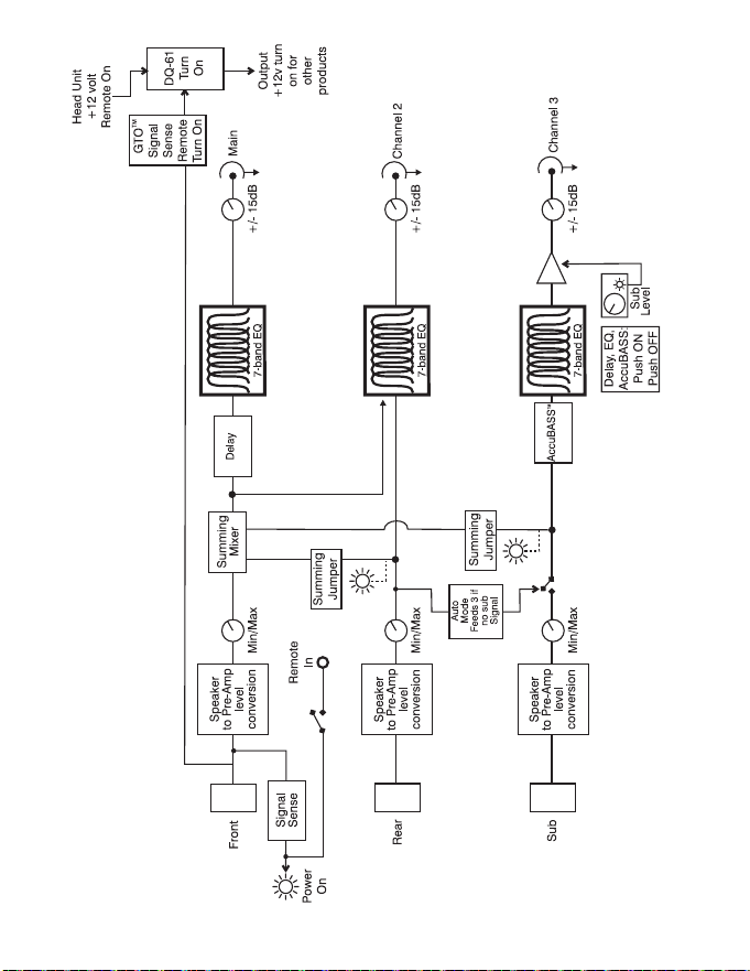
Block Diagram of the DQ-61
Feeling lost? Here’s an internal “roadmap” to help you out. This
simplied block diagram is a map of the paths your signals take inside
the DQ-61. With this diagram you can follow each input through the
processor. If you do have an issue with the hook-up of your DQ-61 and
need to call for technical assistance, please have this diagram available
so we can help you trace the problem and get your system up and
running and sounding as awesome as we know it can.
-----------------------------------------------25 ----------------------------------------------
-----------------------------------------------26 ----------------------------------------------
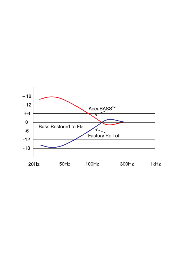
AccuBASS
®
Factory installed ampliers and woofers are generally not designed to
reproduce bass at medium to high volumes. Car manufacturers lter
the bass out of the signal as you increase the volume, in an eort to
protect factory-installed speakers. That’s why we developed the patent
pending AccuBASS® circuit. Aer a quick and easy one-me seng, the
AccuBASS® circuit takes over the bass just as the factory system rolls
o. You get smooth, seamless, rock solid bass response regardless of
volume.
AudioControl’s patent pending AccuBASS® circuit, correcng for bass
roll-o
-----------------------------------------------27 ----------------------------------------------
SengAccuBASS®ForOpmumBassPerformance:
Aer you have hooked up the system and are playing music, play some
tracks with good bass lines, and set the volume at low.
1. On the DQ-61, set the AccuBASS® Level to 12:00 and set all the
EQ controls to at
2. Turn the Threshold all the way down (approximately 7:00)
3. Gradually increase the volume on your factory source unit unl
you hear the bass start to drop out in relaon to the high fre-
quencies. Stop and go to the next step.
4. Turn the Threshold control clockwise unl you hear the bass
come back up.
5. Use the level control to ne-tune the amount of bass remix you
want.
You’re done! Now, every me your source unit gets to that level, the
AccuBASS® will take over and re-equalize the bass. Smooth seamless
bass at all volumes, and with the level control you can even give it a
lile extra kick if you want. Your music your way!

-----------------------------------------------28 ----------------------------------------------
The WARRANTY
People are scared of warranes. Lots of ne print right? Well, fear no
more, this warranty is designed to make you rave about us to your
friends. It’s a warranty that looks out for you and helps you resist
the temptaon to have your friend, “...who’s good with electronics”,
aempt to repair your AudioControl product.
Go ahead and read this warranty, and then take a few days to enjoy
your new DQ-61 before going on line to register your unit at
www.audiocontrolregistraon.com.
We also look forward to your comments while you are registering your
DQ-61. “Condional” doesn’t mean anything ominous. The Federal
Trade Commission tells all manufacturers to use the term to indicate
that certain condions have to be met before they’ll honor the war-
ranty. If you meet all of these condions, we will warranty all materials
and workmanship on the DQ-61 for one year from the date you bought
it (veyearsifitisinstalledbyanauthorizedUnitedStatesAudioCon-
troldealer). We will x or replace it, at our opon, during that me.
Here are the condional condions:
1. You have to go to www.audiocontrol.com warranty and register
your DQ-61 within 15 days aer purchase.
2. You must keep your sales receipt for proof of purchase showing
when and from whom the unit was bought. We’re not the only
ones who require this, so it’s a good habit to get into with any
major purchase.
3. Your DQ-61 must have originally been purchased from an autho-
rized AudioControl dealer. You do not have to be the original owner,
but you do need a copy of the original sales slip.

-----------------------------------------------29 ----------------------------------------------
4. You cannot let anybody who isn’t: (A) the AudioControl factory; (B)
somebody authorized in wring by AudioControl to service your
DQ-61. If anyone other than (A) or (B) messes with your DQ-61,
that voids your warranty.
5. The warranty is also void if the serial number is altered or removed,
or if the DQ-61 has been used improperly. Now that may sound like
a big loophole, but here is all we mean by it. Unwarranted abuse
is: (A) physical damage (don’t use the DQ-61 for a car jack); (B) im-
proper connecons (120 volts into the power jack can fry the poor
thing); (C) sadisc things. This is the best product we know how to
build, but if you mount it to the front bumper of your car, some-
thing will go wrong. If an authorized United States AudioControl
dealer installs the DQ-61, the warranty is ve years. Assuming you
conform to 1 through 5, and it really isn’t all that hard to do, we get
the opon of xing your old unit or replacing it with a new one.
LEGALESE SECTION
This is the only warranty given by AudioControl. This warranty gives
you specic legal rights that vary from state to state. Promises of how
well the DQ-61 will perform are not implied by this warranty. Other
than what we have covered in this warranty, we have no obligaon,
express or implied. Also, we will not be obligated for direct or indirect
consequenal damage to your system caused by hooking up the DQ-61.
Failure to register warranty informaon negates any service claims.

-----------------------------------------------30 ----------------------------------------------
DQ-61 SPECIFICATIONS
All specicaons are measured at 14.4 VDC (standard automove
voltage.) As technology advances, AudioControl reserves the right to
connuously change our specicaons, in our never-ceasing quest for
audio righteousness.
Maximum speaker-level input ............................... 400 was per channel
Maximum output level ............................................................... 7.5 Vrms
Output gain .................................................................................+/-12 dB
Frequency response ............................................................ 10 Hz-22 kHz
Total harmonic distoron ................................................................0.01%
Input Impedance .......................................................................20 Kohms
Equalizaon Frequencies
Front/Rear .............. 125Hz, 175Hz, 250Hz, 500Hz, 1kHz, 2kHz, 8kHz
Sub Output ..............31.5Hz, 40Hz, 50Hz, 63Hz, 80Hz, 100Hz, 125Hz
Signal Delay
Le /Right Max Delay ............................................................... 10 ms
Front/Sub Max Delay ................................................................35 ms
Output Impedance .................................................................. 150 Ohms
Power supply ..........................................High headroom PWM switching
Power draw .................................................................................. 350 mA
Recommended fuse rang ........................................................... 2 Amps
Remote trigger max output current .............................................. 1 Amp
Size ........................................................................... 8.6”W x 5”D x 1.25”
Weight ............................................................................................... 3 lbs
©2018 AudioControl, Inc. All rights reserved

-----------------------------------------------31 ----------------------------------------------
AudioControl, Making Good Sound Great and DQ-61 are all trademarks
of AudioControl Inc. This manual was conceived, designed, and wrien
on a cold and windy day in the Pacic Northwest which is what the
locals from Seale call “spring.”
22410 70
th
Ave West
Mountlake Terrace, WA 98043 USA
Phone 425-775-8461 • www.audiocontrol.com
®
Making Good Sound Great
™
P/N 913-121-0 Rev B