
!
Version 1.0
Copyright © 2026
T-BEAM 1W
User Guide

About This Guide
This document is intended to help users set up the basic software development
environment for developing applications using hardware based on the T-BEAM 1W.
Through a simple example, this document illustrates how to use Arduino, including the
menu based configuration wizard, compiling the Arduino and firmware download to the
ESP32 module.
Release Notes
Date
Version
Release notes
2026.06
V1.0 First release.

Table of Contents
1. Introduction! 1".............................................................................................................................
1.1.
T-BEAM 1W
...............................................................................................................................1"
1.2.
Arduino
1".....................................................................................................................................
1.3. Preparation! 1".................................................................................................................................
2. Get Started! 2".............................................................................................................................
2.1.
Download the Arduino Software
! ...............................................................................................2!
2.1.1. Install Prerequisites
! .......................................................................................................2!
2.1.2. Toolchain Setup!
............................................................................................................2!
2.2.
Install the Arduino Software
! ......................................................................................................3!
2.3. Set up Path!
................................................................................................................................3!
! ................................................................................................................................4!
! 5"..................................................................................................................................
!
...........................................................................................................................6"
3. Configure
4. Connect
5. Test Demo
6. Upload Sketch
! 7".......................................................................................................................
6.1. Build and Flash! 7"..........................................................................................................................
6.2. Monitor! 8".......................................................................................................................................
7. SSC Command Reference! 9".....................................................................................................
7.1. op! 9"...............................................................................................................................................
7.2. sta! 9"..............................................................................................................................................
7.3. ap! 10".............................................................................................................................................
7.4. mac! 10"..........................................................................................................................................
7.5. dhcp! 11".........................................................................................................................................
7.6. ip! 11"..............................................................................................................................................
7.7. reboot! 12".......................................................................................................................................
7.8. ram! 12...........................................................................................................................................
Appendix - Notices ......................................................................................................................................13
I.
Federal Communications Commission (FCC) Declaration of Conformity ..............................................13

!
1. Introduction
1. Introduction
1.1. T-BEAM 1W
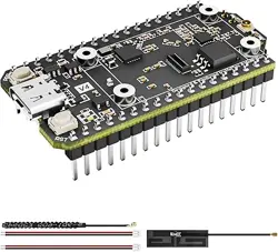
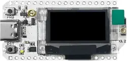
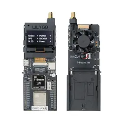
T-BEAM 1W is a development board. It can work independently.
It consists of ESP32-S3 MCU supporting Wi-Fi + BLE communication protocol and
motherboard PCB. This product also features a 1.3-inch 128x64 OLED display.
And this product has GPS positioning and LoRa function. LoRa chip is SX1262.
For applications ranging from low-power sensor networks to the most demanding tasks.
At the core of this module is the ESP32S3R8 chip.
ESP32-S3 integrates Wi-Fi (2.4 GHz band) and Bluetooth 5.0 solutions on a single chip,
along with dual high performance cores and many other versatile peripherals. ESP32
provides a robust, highly integrated platform to meet the continuous demands for
efficient power usage, compact design, security.
Xinyuan provides the basic hardware and software resources that empowers
application developers to build their ideas around the ESP32-S3 series hardware. The
software development framework provided by Xinyuan is intended for rapidly
developing Internet-of-Things (IoT) applications, with Wi-Fi, Bluetooth, flexible power
management and other advanced system features.
The manufacturer is Shenzhen Xin Yuan Electronic Technology Co., Ltd.
1.2. Arduino
A set of cross-platform applications written in Java. The Arduino Software IDE is
derived from the Processing programming language and the integrated development
environment of the Wiring program. Users can develop applications in Windows/Linux/
MacOS based on Arduino. It is recommended to use Windows 10. Windows OS has
been used as an example in this document for illustration purposes.
1.3. Preparation
To develop applications for ESP32-S3 you need:
• PC loaded with either Windows, Linux or Mac operating system
• Toolchain to build the Application for ESP32-S3
• Arduino that essentially contains API for ESP32-S3 and scripts to operate the
Toolchain
• CH9102 serial port driver
• The ESP32-S3 board itself and a USB cable to connect it to the PC
Lilygo
! /121
2026.06
!
2. Get Started
2. Get Started
2.1. Download the Arduino Software
The quickest how to install the Arduino Software (IDE) on Windows machines
2.1.1. Quick Start Guide
The website provides a quick start tutorial
• Windows:
https://www.arduino.cc/en/Guide/Windows
• Linux:
https://www.arduino.cc/en/Guide/Linux
• Mac OS X:
https://www.arduino.cc/en/Guide/MacOSX
2.1.2. Installation steps for Windows platform Arduino
Xinyuan
! /122
2026.06
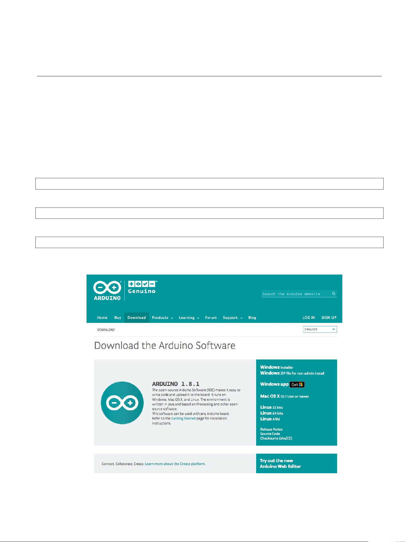
Enter the download interface, select Windows installer to install directly
!
2. Get Started
2.2. Install the Arduino Software
Xinyuan
! /123
2026.06
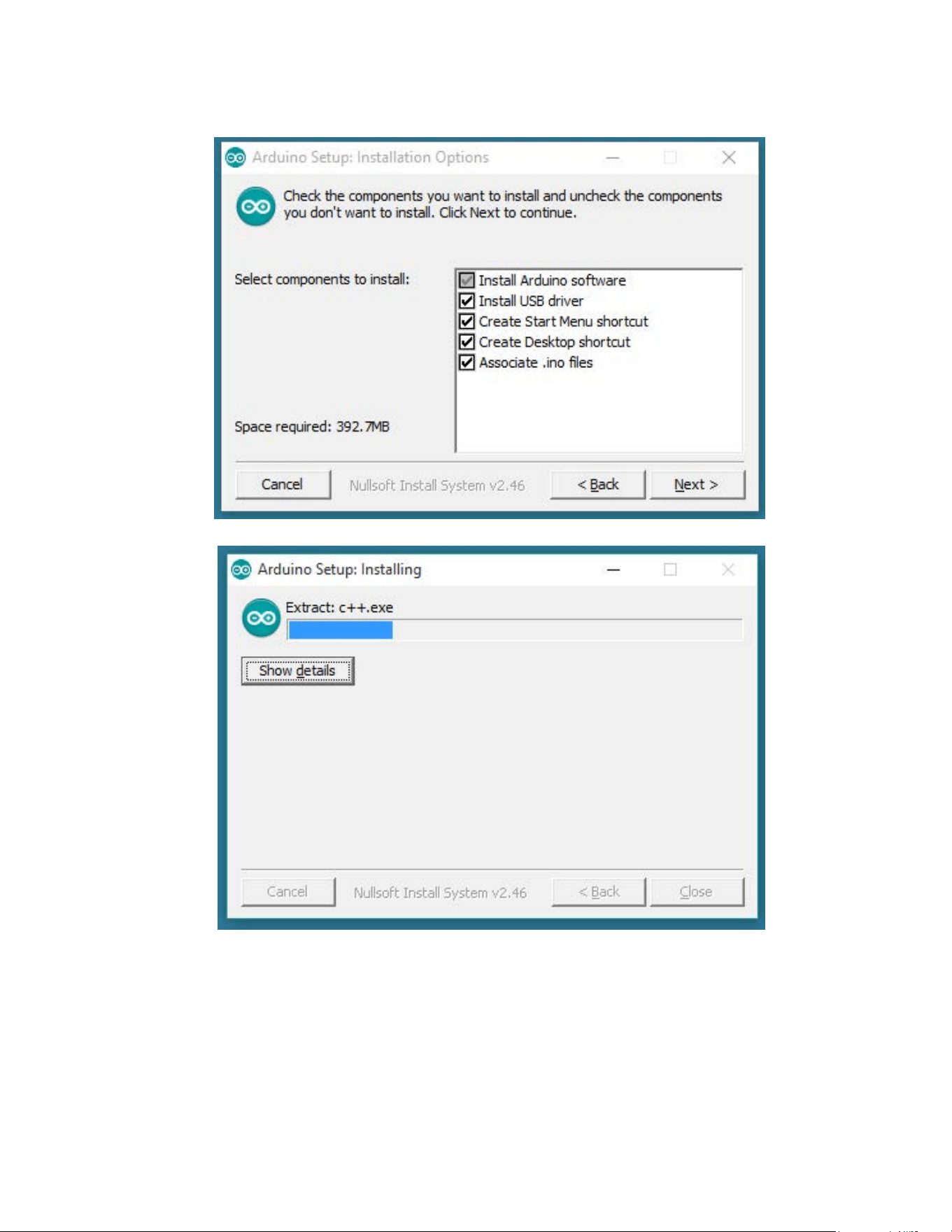
Wait for installation
!
3. Start a Project
3. Configure
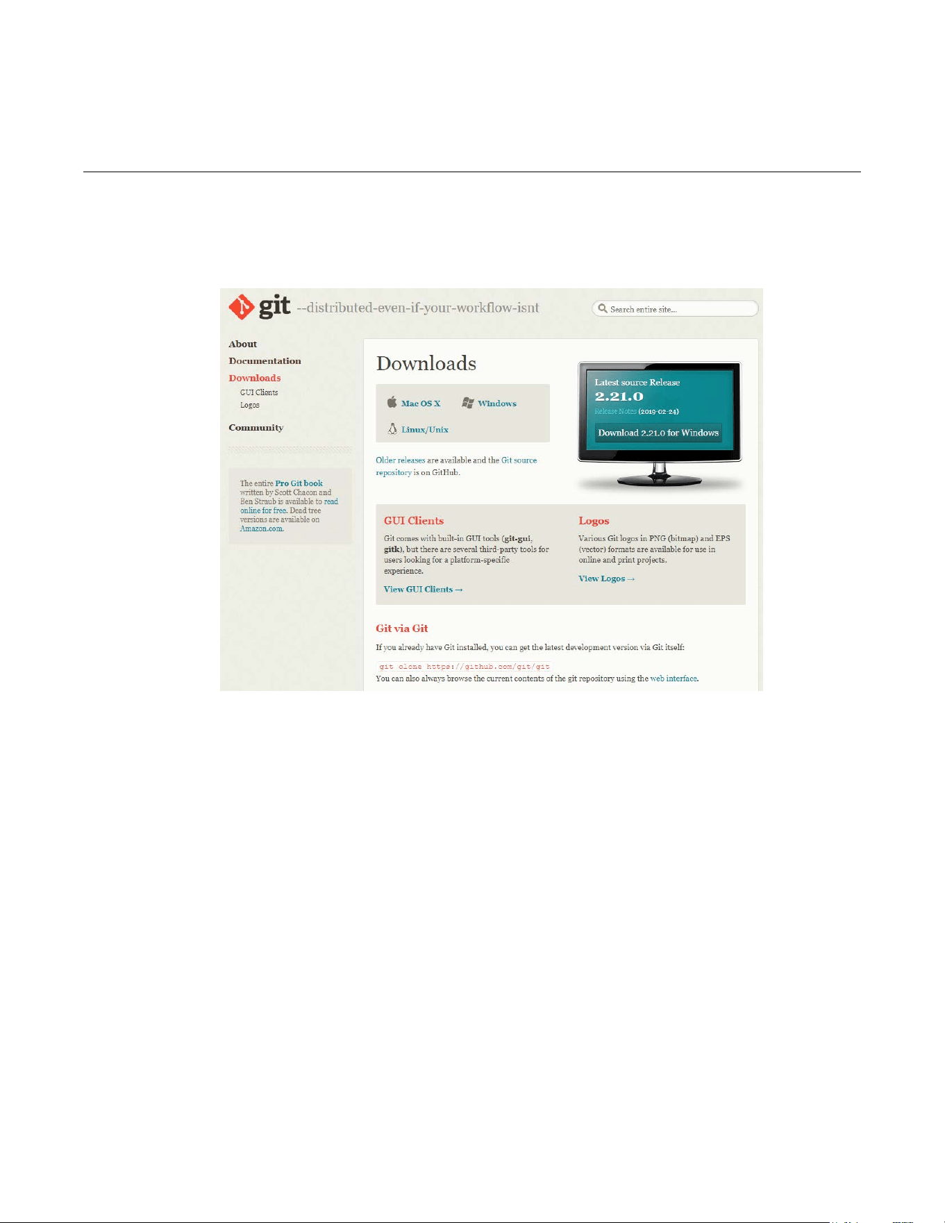
Download the installation package Git.exe
Xinyuan
! /124
2026.06
3.1. Download Git
3.2. Pre-build configuration
Click Arduino icon, then right click and select ``Open folder where ``
Select hardware ->
Mouse ** Right click ** ->
Click Git Bash Here
3.3. Cloning a remote repository
$ mkdir espressif
$ cd espressif
$ git clone --recursive https://github.com/espressif/arduino-esp32.git esp32

!
4. Connect
4. Connect
You are almost there. To be able to proceed further, connect ESP32-S3 board to PC,
check under what serial port the board is visible and verify if serial communication
works.
Xinyuan
! /125
2026.06
!
4. Configure
5.
Test Demo
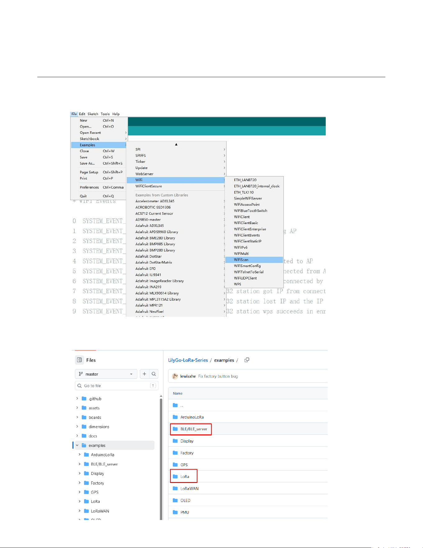
Select File>>Example>>WiFi>>WiFiScan
!
Xinyuan
! /126
2026.06
BLE & LoRa Demo: https://github.com/Xinyuan-LilyGO/LilyGo-LoRa-Series/
tree/master/examples

!
5. Build and Flash
6. Upload Sketch
6.1. Select Board
Tools<<Board<<ESP32S3 Dev Module
Xinyuan
! /127
2026.06
Upload
Sketch
<< Upload
!
5. Build and Flash
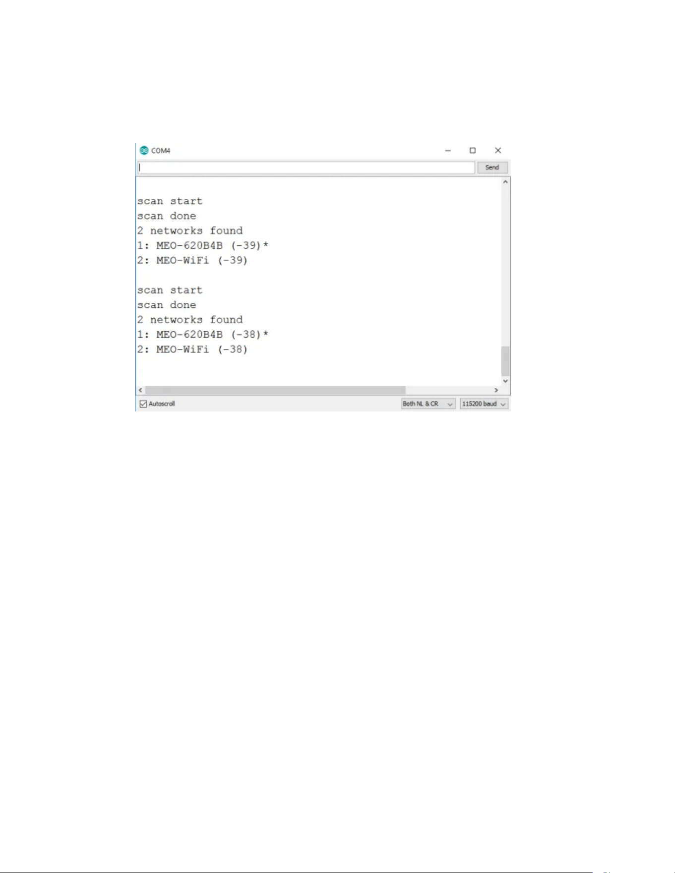
6.2. Serial Monitor
Tools << Serial Monitor
Xinyuan
! /128
2026.06
!
6. SSC Command Reference
7. SSC Command Reference
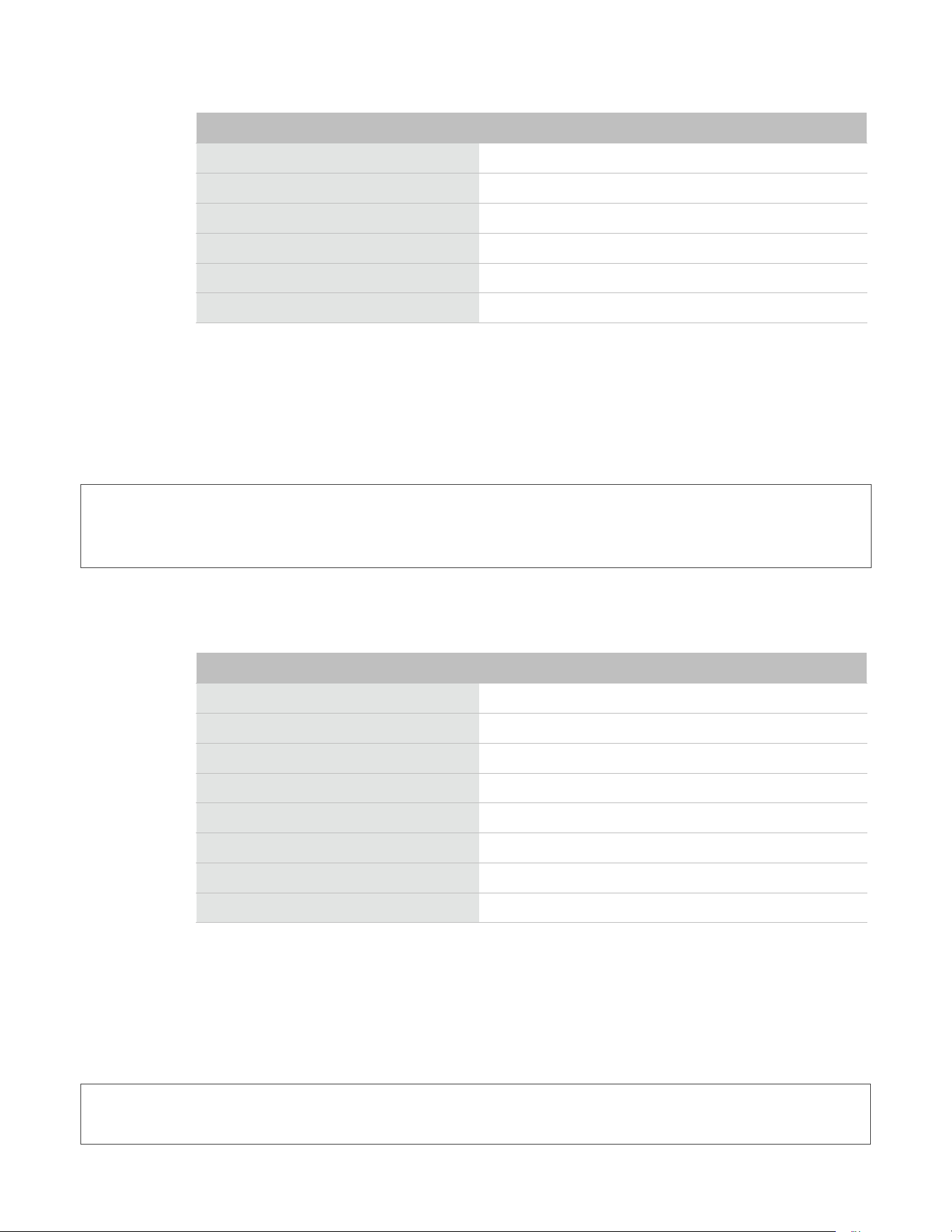
Here lists some common Wi-Fi commands for you to test the module.
7.1. op
Description
op commands are used to set and query the Wi-Fi mode of the system.
Example
op-Q
op-S-owmode
Parameter
7.2. sta
Description
sta commands are used to scan the STA network interface, connect or disconnect AP, and
query the connecting status of STA network interface.
Example
sta-S[-sssid][-bbssid][-nchannel][-h]
sta-Q
sta-C[-sssid][-ppassword]
sta-D
Parameter
Table 6-1. op Command Parameter
Parameter
Description
-Q
Query Wi-Fi mode.
-S
Set Wi-Fi mode.
wmode
There are 3 Wi-Fi modes:
• mode = 1: STA mode
• mode = 2: AP mode
• mode = 3: STA+AP mode
Table 6-2. sta Command Parameter
Parameter
Description
-S scan
Scan Access Points.
Xinyuan
! /129
2026.06
!
6. SSC Command Reference
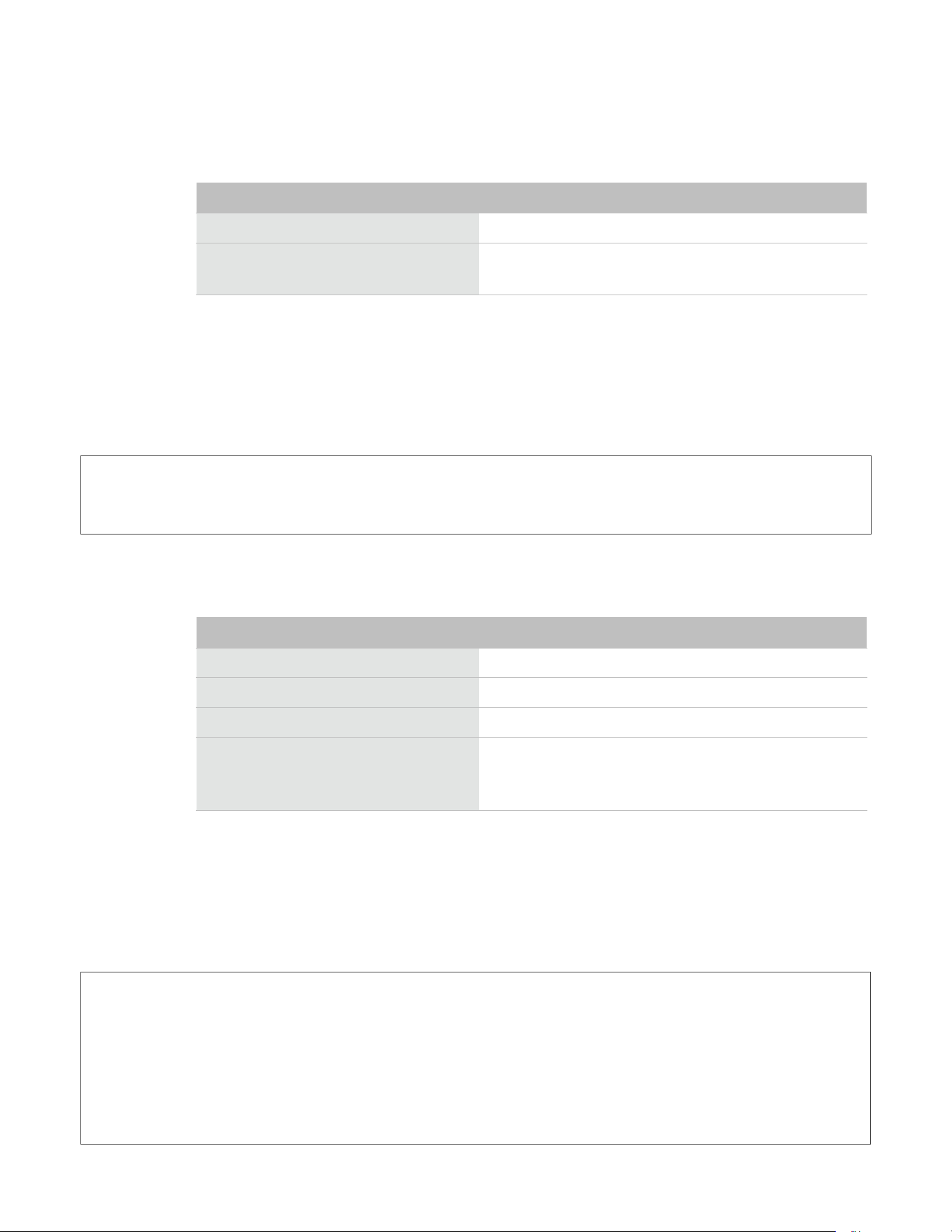
7.3. ap
Description
ap commands are used to set the parameter of AP network interface.
Example
ap-S[-sssid][-ppassword][-tencrypt][-nchannel][-h][-mmax_sta]
ap–Q
ap–L
Parameter
7.4. mac
Description
mac commands are used to query the MAC address of the network interface.
Example
mac-Q[-omode]
-s ssid
Scan or connect Access Points with the ssid.
-b bssid
Scan the Access Points with the bssid.
-n channel
Scan the channel.
-h
Show scan results with hidden ssid Access Points.
-Q
Show STA connect stutus.
-D
Disconnected with current Access Points.
Parameter
Description
Table 6-3. ap Command Parameter
Parameter
Description
-S
Set AP mode.
-s ssid
Set AP ssid.
-p password
Set AP password.
-t encrypt
Set AP encrypt mode.
-h
Hide ssid.
-m max_sta
Set AP max connections.
-Q
Show AP parameters.
-L
Show MAC Address and IP Address of the connected station.
Xinyuan
! /1210
2026.06
!
6. SSC Command Reference
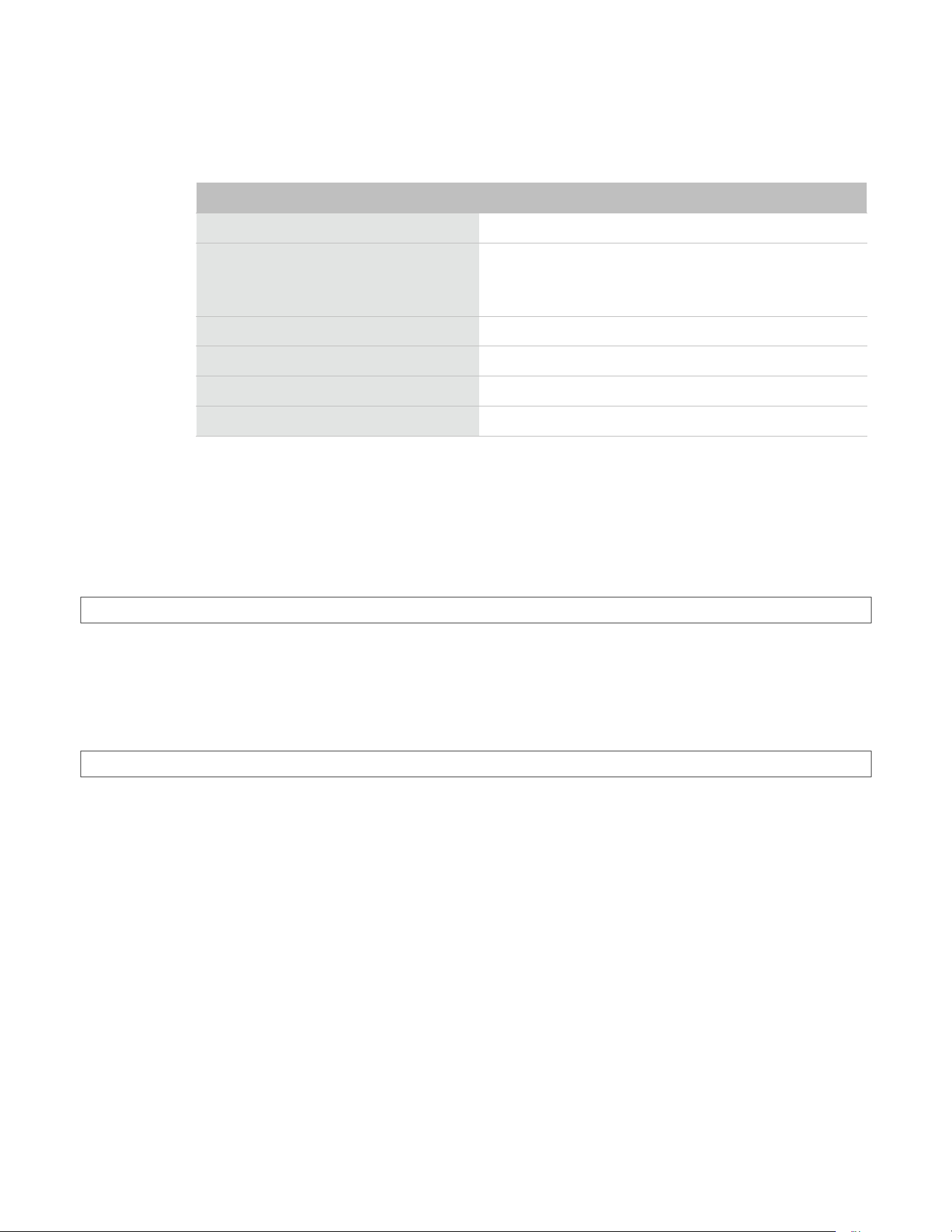
Parameter
7.5. dhcp
Description
dhcp commands are used to enable or disable dhcp server/client.
Example
dchp-S[-omode]
dhcp-E[-omode]
dhcp-Q[-omode]
Parameter
7.6. ip
Description
ip command are used to set and query the IP address of the network interface.
Example
ip-Q[-omode]
ip-S[-iip][-omode][-mmask][-ggateway]
Table 6-4. mac Command Parameter
Parameter
Description
-Q
Show MAC address.
-o mode
• mode = 1: MAC address in STA mode.
• mode = 2: MAC address in AP mode.
Table 6-5. dhcp Command Parameter
Parameter
Description
-S
Start DHCP (Client/Server).
-E
End DHCP (Client/Server).
-Q
show DHCP status.
-o mode
• mode = 1 : DHCP client of STA interface.
• mode = 2 : DHCP server of AP interface.
• mode = 3 : both.
Xinyuan
! /1211
2026.06
!
6. SSC Command Reference
Parameter
7.7. reboot
Description
reboot command is used to reboot the board.
Example
reboot
7.8. ram
ram command is used to query the size of the remaining heap in the system.
Example
ram
Table 6-6. ip Command Parameter
Parameter
Description
-Q
Show IP address.
-o mode
• mode = 1 : IP address of interface STA.
• mode = 2 : IP address of interface AP.
• mode = 3 : both
-S
Set IP address.
-i ip
IP address.
-m mask
Subnet address mask.
-g gateway
Default gateway.
Xinyuan
! /1212
2026.06

FCC Caution:
Any Changes or modifications not expressly approved by the party responsible for
compliance could void the user's authority to operate the equipment.
This device complies with part 15 of the FCC Rules. Operation is subject to the following
two conditions: (1) This device may not cause harmful interference, and (2) this device
must accept any interference received, including interference that may cause undesired
operation.
This transmitter must not be co-located or operating in conjunction with any other antenna
or transmitter.
IMPORTANT NOTE:
Note: This equipment has been tested and found to comply with the limits for a Class B digital
device, pursuant to part 15 of the FCC Rules. These limits are designed to provide reasonable
protection against harmful interference in a residential installation. This equipment generates,
uses and can radiate radio frequency energy and, if not installed and used in accordance with
the instructions, may cause harmful interference to radio communications. However, there is
no guarantee that interference will not occur in a particular installation. If this equipment does
cause harmful interference to radio or television reception, which can be determined by turning
the equipment off and on, the user is encouraged to try to correct the interference by one or
more of the following measures:
—Reorient or relocate the receiving antenna.
—Increase the separation between the equipment and receiver.
—Connect the equipment into an outlet on a circuit different from that to which the receiver is
connected.
—Consult the dealer or an experienced radio/TV technician for help.
FCC Radiation Exposure Statement:
This equipment complies with FCC radiation exposure limits set forth for an
uncontrolled environment .This equipment should be installed and operated with
minimum distance 20cm between the radiator& your body.