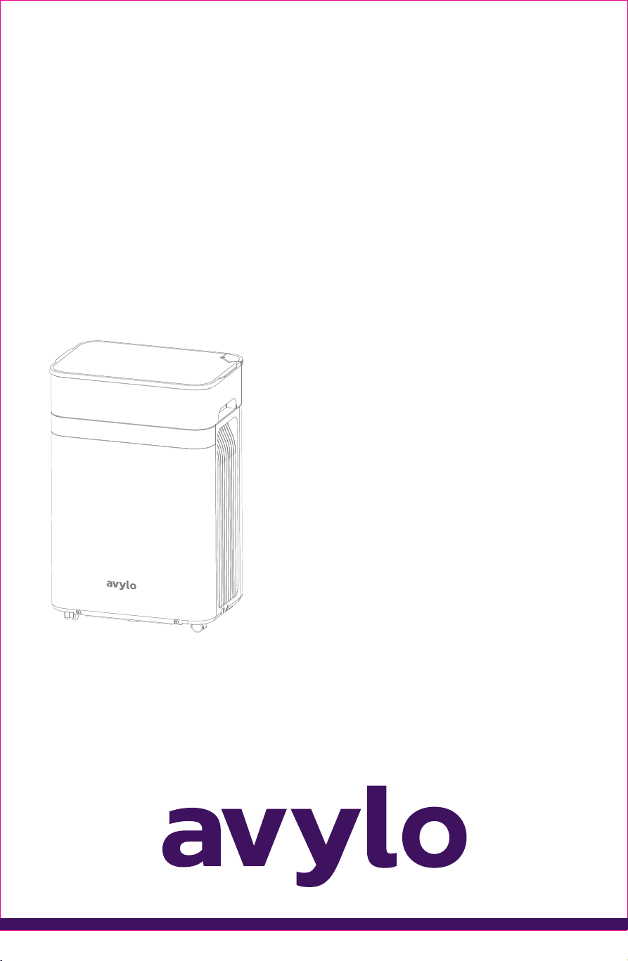
MODEL: ADC018
Dehumidifier
User Manual
READ AND SAVE THESE INSTRUCTIONS

Thanks for
Choosing
Your support means the world to us.
We hope you enjoy our product as much as
we enjoyed creating it.

CONTENTS
01
GET TO KNOW YOUR
DEHUMIDIFIER
1
03
CONTROL PANEL
OVERVIEW
2-4
05
FREQUENTLY ASKED
QUESTIONS
8
07
SAFETY WARNINGS
10 - 16
08
WARRANTY SUPPORT
16
02
TECHNICAL
SPECIFICATIONS
2
04
OPERATING
INSTRUCTIONS
5 - 8
06
ERROR CODES
9
Thank you for purchasing the Avylo Dehumidifier. To ensure proper use and maintenance, please
read this user manual carefully before operating the unit.
1
GET TO KNOW YOUR DEHUMIDIFIER
DEAR CUSTOMER
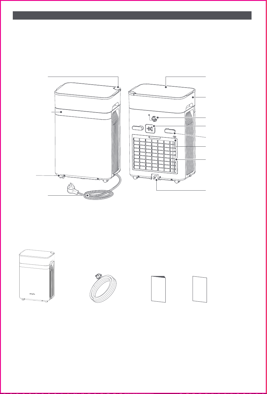
Product Overview
Package Contents
1x
Dehumidifier
1x
User Manual
1×
Drain Hose with Connector
(5 m / 15ft, stored inside
the water tank)
2×
Cards
(Quick Start Guide ×1,
Service Card ×1)
Control Panel
Caster
Wheels
Power Cord
Bottom Drain
Outlet
Built-In Pump
Drain Outlet
Power Cord
Storage Slot
Cord Wrap Clip
Sensor
Dust Filter
Water Tank
Water Tank
Cover
Tank Drain
Outlet
2
Model
Rated Voltage/Frequency
Rated Power
Stand Power (65°F/60%RH)
Refrigerant/Charge
ADC018
115V / 60Hz
410W
235W
R32 / 155g
TECHNICAL SPECIFICATIONS
The applicable operating temperature range for this unit is 5-35℃;
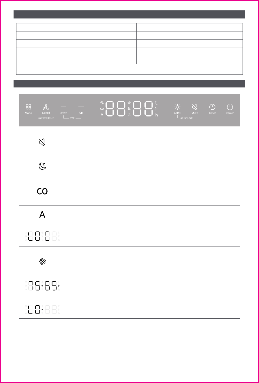
CONTROL PANEL OVERVIEW
Mute Indicator�
Lights up when the Mute function is enabled and turns off when
Mute is disabled.�
Sleep Mode Indicator�
Lights up when Sleep Mode is activated and turns off when Sleep
Mode is deactivated.�
Continuous Mode Indicator (CO)�
Lights up when Continuous Mode is activated and turns off when
Continuous Dehumidification is deactivated.�
Auto Mode Indicator (A)�
Lights up when Auto Mode is activated and turns off when Auto
Dehumidification is deactivated.�
Child Lock�
The display shows LOC.
Humidity / Temperature Display�
“75” on the left indicates humidity. "65” on the right indicates
temperature.�
Low Humidity Indicator�
Displays when ambient relative humidity (RH) is below 30%.
Filter-Clean Indicator�
Lights up blue every 1,000 hours of operation, indicating that the
filter needs to be cleaned.�Press and hold the Fan Speed button for 3
seconds to turn off the indicator and reset the Filter-Clean indicator.�
3
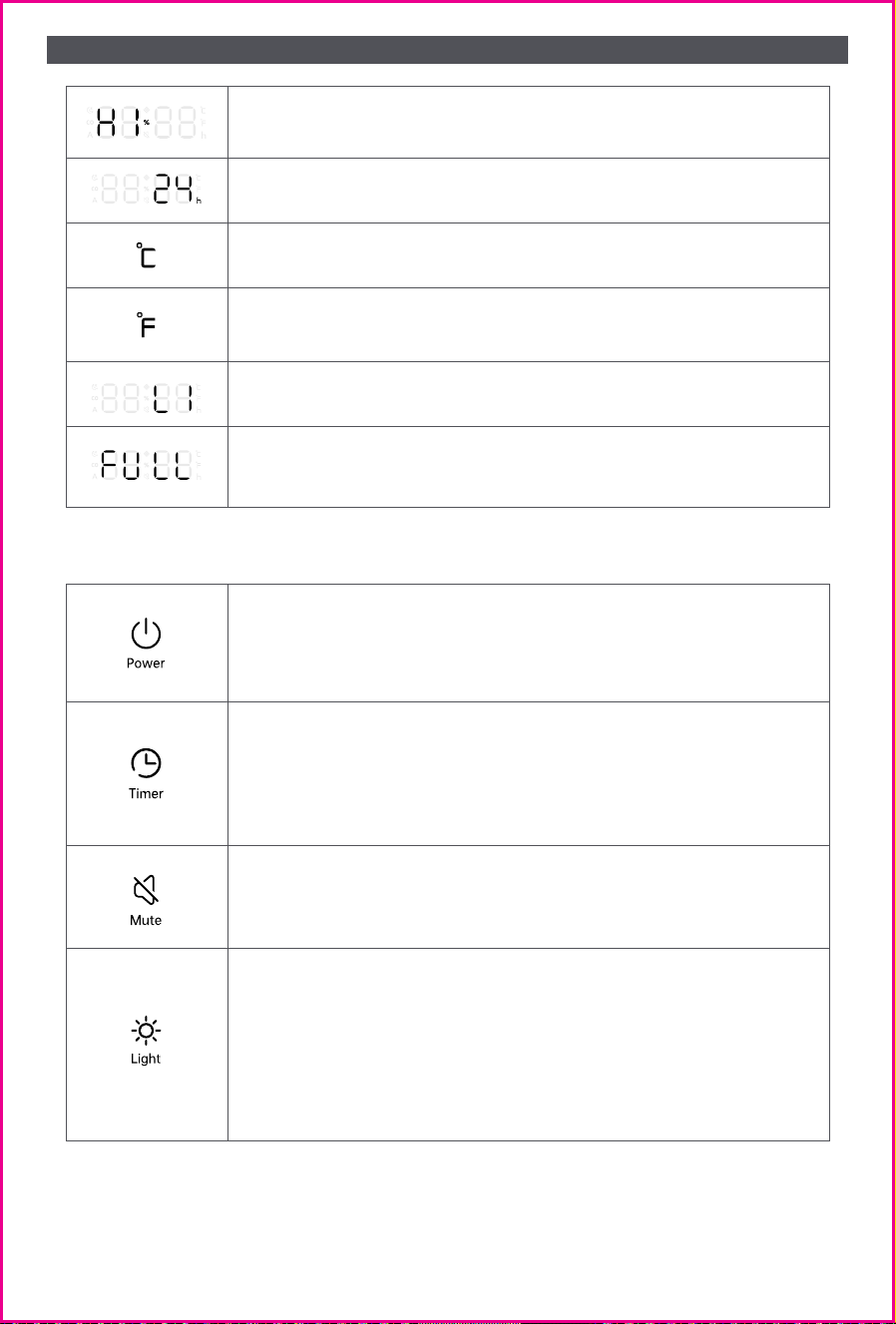
CONTROL PANEL OVERVIEW
High Humidity Indicator�
Displays when ambient relative humidity (RH) is above 90%.
Timer Display�
Shows the current timer setting in Timer mode.
Celsius Indicator (°C)�
Lights up when the temperature is displayed in Celsius.
Fahrenheit Indicator (°F)�
Lights up when the temperature is displayed in Fahrenheit (factory
default).
Fan Speed Display�
Displays L1–L3, indicating fan speed levels.
Water Tank Full Indicator�
When the water tank is full or not properly installed, the digital
display shows “FULL.”
Power Button
Press once to turn the unit ON or OFF.�The dehumidifier features an
Auto-Resume function and will automatically restart with the
previous settings after a power outage or when the unit is turned
back on.
Light Button
Press once to cycle through lighting modes:�Screen on, ambient light
on (default) → Screen off, ambient light on → All lights off → Return
to default.
Humidity Indicator Colors:
● Blue: Below 40% RH
● Green: 40%–60% RH
● Orange: Above 60% RH
Timer Button
Press once to enter Timer ON setting mode.Press and hold for 3S to
disable Timer.In Timer mode, press the “+” , “–” or Timer button to
adjust the timer in 1-hour increments, cycling from 0 to 24 hours.-
Press and hold the “+” or “–” button to quickly scroll through 0 to 24
hours.
Mute Button
Press once to enable or disable the beep sound.�When muted, all
button tones and alert beeps are turned off, and the Mute icon lights
up on the display.
4
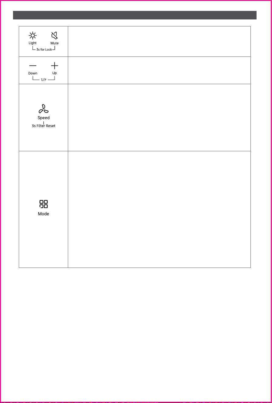
CONTROL PANEL OVERVIEW
Press the Fan Speed button to cycle through fan speeds: L1 → L2 →
L3.
In Continuous or Auto mode, pressing the Fan Speed button allows
you to adjust the fan speed.
Short press: Adjust the fan speed
Long press: Reset the filter
Sleep mode: Fan speed cannot be adjusted.
When the filter-clean indicator lights up, clean the filter then press
and hold the Fan Speed button for 3 seconds to reset the filter.
Press the Mode button to cycle through operating modes: Continu-
ous → Auto → Sleep.
① Continuous Mode
The unit dehumidifies continuously.
Fan speed can be adjusted in this mode.
② Auto Mode
Set your preferred target room humidity (default: 60% RH).
The unit stops automatically when the ambient humidity reaches the
set value.
If the ambient humidity rises above the set value, the unit will
restart automatically.
Fan speed can be adjusted in Auto mode.
③ Sleep Mode
The unit operates at L1 fan speed with all lights off.
In Sleep mode, press “+” or “–” to adjust the Auto humidity setting.
The fan speed remains locked at L1.
If there is no operation for 3 seconds, all lights will turn off.
While the unit is ON, press and hold both the “+” and “–” buttons for
3 seconds to switch the temperature display between Celsius (°C)
and Fahrenheit (°F).
Press and hold both the Light and Mute buttons for 3 seconds to
activate or deactivate the Child Lock function.
5
OPERATING INSTRUCTIONS
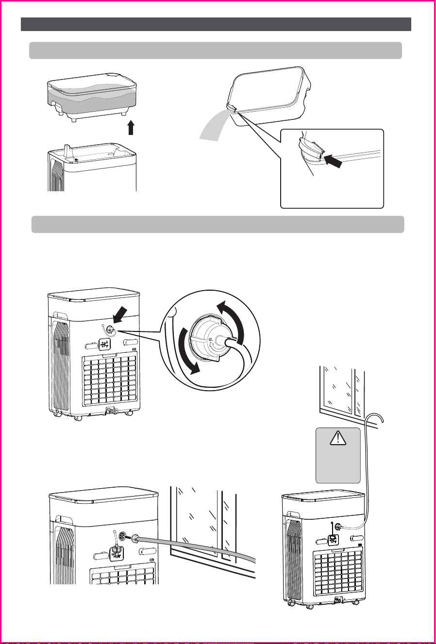
Drainage Method 1: Manual Drain
Drainage Method 2: Continuous Drain with Built-In Pump
Remove the water tank and
pour out the collected water.
The tank drain outlet opens
automatically when pouring.
1. Empty the water tank.
2. Unscrew the rear cover and remove the drain plug.
3. Screw the drain hose connector onto the unit.�
Tip:
Maximum
drain height
- 15ft
6
OPERATING INSTRUCTIONS
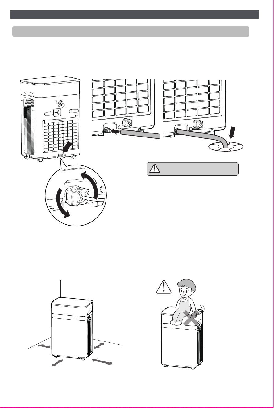
A drain hose can be connected to the bottom drain outlet.
Please purchase the hose separately at a hardware store.
Recommended hose size: ½-inch inner diameter.
1. Unscrew the rear cover and remove the drain plug.
2. Attach the drain hose, ensuring the hose outlet points toward a drain.
Tip: The bottom drain outlet should not
be positioned higher than the drain port.
Drainage Method 3: Continuous Drain with Bottom Drain
Precautions / Safety Notes
1. Keep at least 30 cm (12 in) of clearance between the unit’s air inlet/outlet and
surrounding walls.
(See Figure 1)
2. Do not sit or stand on the unit.
(See Figure 2)
Figure 1 Figure 2
12in
12in
7
OPERATING INSTRUCTIONS
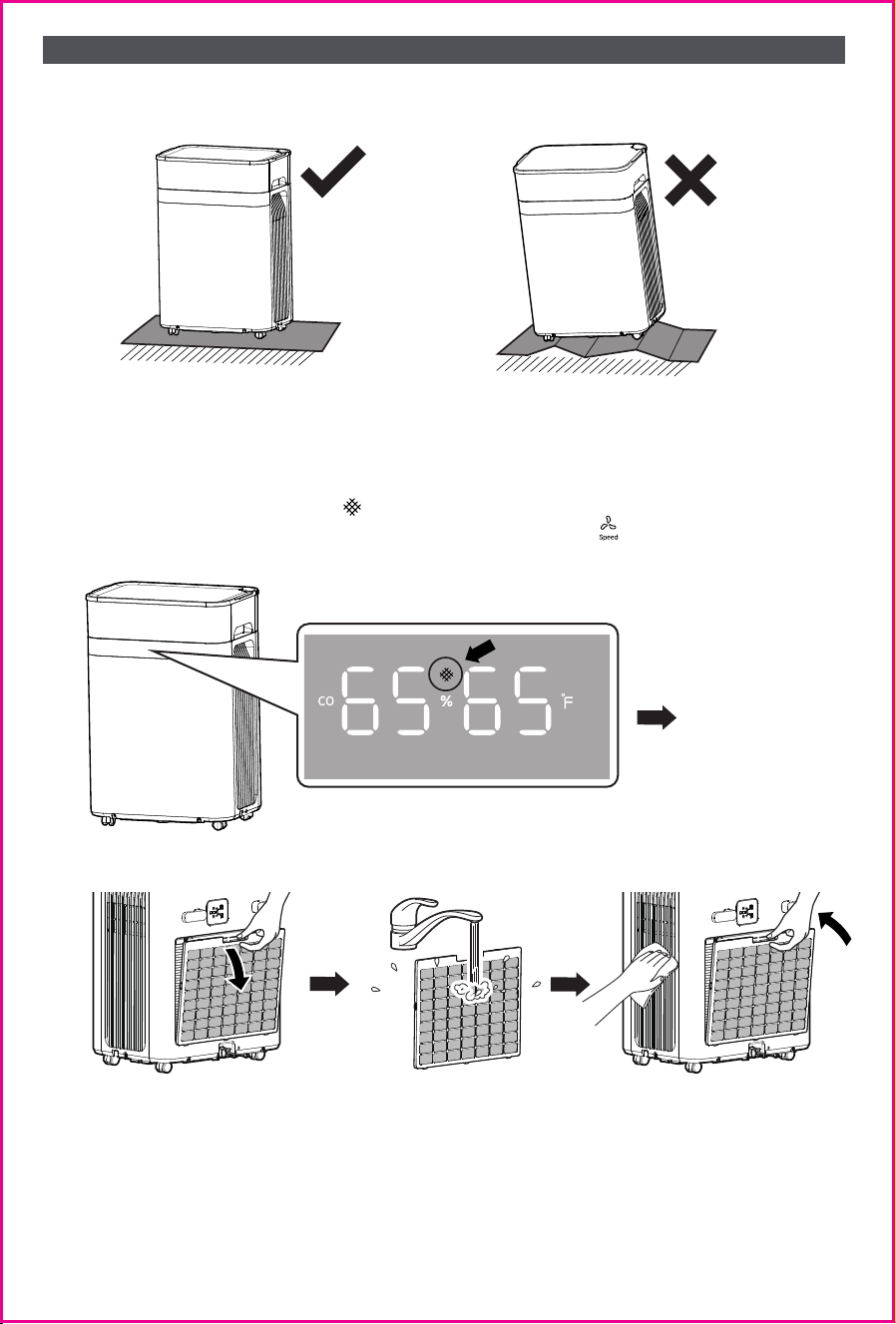
Figure 3 Figure 4
level surface
4. Filter Cleaning
Clean the filter regularly to maintain optimal performance.
a. When the filter-clean indicator lights up, clean the filter as shown in the illustration.
b. After cleaning the filter, press and hold the Fan Speed button for 3 seconds to reset
the filter cleaning timer.
3. Place the unit on a stable and level surface. (See Figure 3-4)
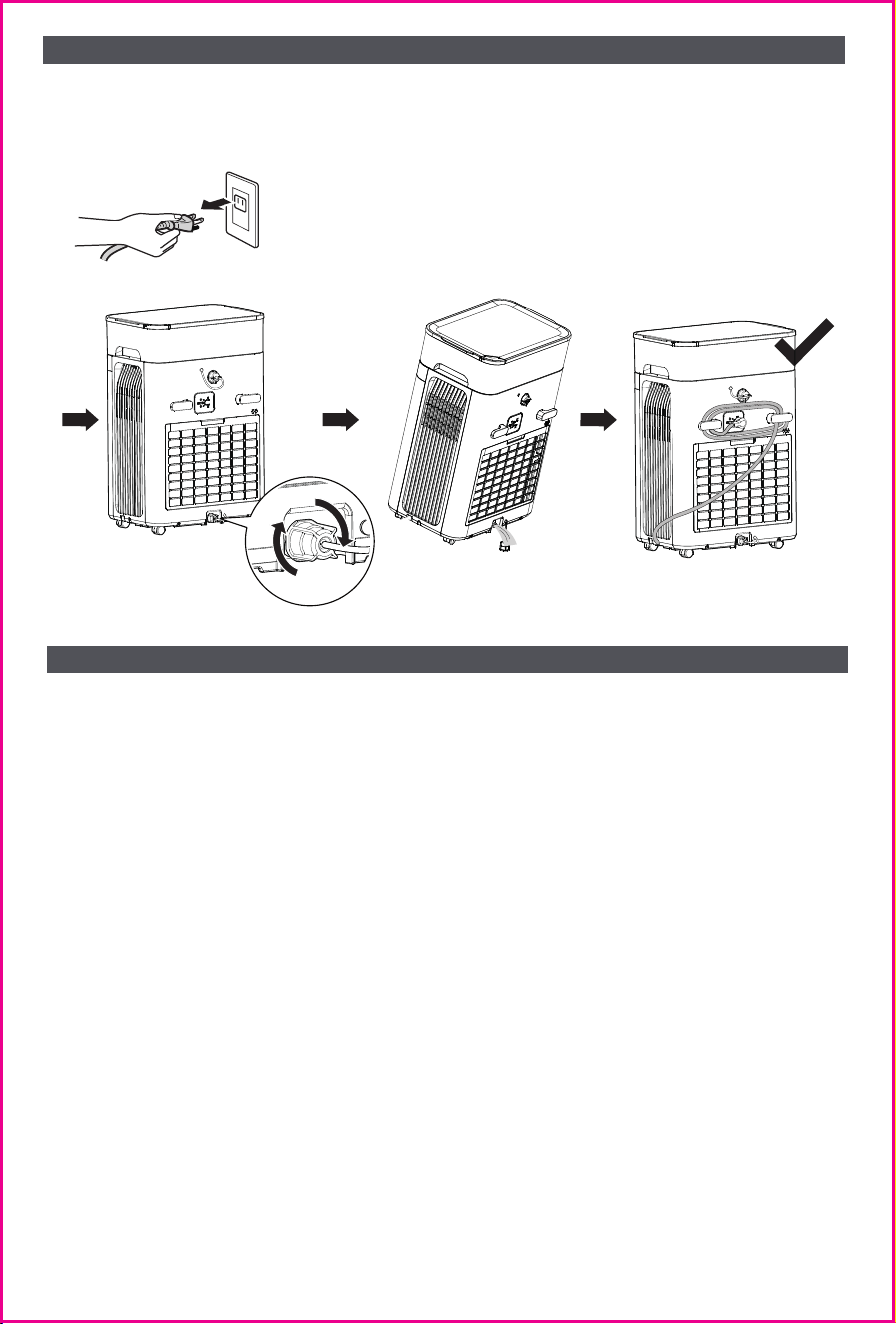
5. Product Storage & Relocation (Recommended)
a. Unplug the unit.
b. Drain any remaining water: Open the bottom drain outlet to fully drain the unit.
c. Wrap the power cord and store it in the cord slot.
8
OPERATING INSTRUCTIONS
a) Why is the dehumidification capacity different from the advertised value?
• Dehumidification performance varies depending on ambient temperature and humidity
conditions.
• In high-humidity environments, the unit may remove moisture more quickly. In lower-humid-
ity conditions, the dehumidification rate decreases.
• This behavior is normal and consistent with industry testing standards.
b) Why does the humidity displayed on the unit differ from my hygrometer?
• All humidity measurement devices have accuracy tolerances and may require periodic
calibration. This unit uses a humidity sensor with an accuracy of ±5% RH.
• If your hygrometer has a different calibration offset (for example, reading higher while the
unit reads lower), noticeable differences may occur.
• Humidity levels can also vary within a room. For the most accurate comparison, place your
hygrometer near the unit’s air inlet; readings should become more consistent.
c) Why is there water on the floor or on the unit?
• Similar to condensation forming on a cold beverage, moisture may condense on the exterior
of the unit.
• Because the dehumidifier operates using refrigeration, its surface and base may become
cooler than the surrounding air.
• In very high-humidity conditions, water droplets may form on the unit or nearby surfaces.
This is normal and will subside as room humidity decreases during operation.
FREQUENTLY ASKED QUESTIONS (REVISED)

d) Why does the unit take a long time to reach the set humidity or fail to reduce
humidity?
• Dehumidification capacity is limited by room size, airflow, and moisture infiltration.
• In large spaces or poorly sealed rooms, moisture from outside may continuously enter,
preventing the unit from reaching the set humidity level.
• Ensure all doors and windows are fully closed for optimal performance.
E) Why is the water tank leaking?
• There may be foreign objects on the sealing silicone ring at the bottom of the water tank.
Please clean the silicone ring thoroughly.
FREQUENTLY ASKED QUESTIONS (REVISED)
ERROR CODES
E1
E5
E4
E7
E8
Error Code Description
Symptom /
Temporary Measures
Recommended Solution
Ambient Tempera-
ture Sensor Fault
Water Sensor Fault
Fan Fault
High Temperature
Fault
Communication
Fault
The unit cannot detect
ambient temperature.
Operation is limited to
Continuous Mode, and
Auto Mode is unavail-
able.
The water sensor
indicates a fault,
possibly due to a
clogged drain hose or a
faulty pump.
Fan malfunction. The
unit will stop operating.
Compressor over-tem-
perature protection
activated, possibly due
to high ambient
temperature or
restricted airflow. The
unit may automatically
resume operation after
internal protection
resets.
The control board
cannot communicate
with internal compo-
nents. The unit will
operate in Safe Mode,
with dehumidification
reduced by approxi-
mately 18%.
Continue operating in
Continuous Mode and
contact customer
support.
Please check drain hose
first. If drain hose is
not clogged, please
contact customer
support Please use
bottom drainage for
temporary use.
Contact customer
support.
Restart the unit after
it cools down. Ensure
adequate ventilation. If
the error persists,
contact customer
support.
The unit may continue
operating in Safe Mode.
Contact customer
support for service
assistance.
9
WARNING for Using R32 Refrigerant:
Transportation, marking and storage for units that employ flammable refrigerants
1. General
The following information is provided for units that employ FLAMMABLE REFRIGERANTS.
2. Transport of equipment containing flammable refrigerants
Attention is drawn to the fact that additional transportation regulations may exist with
respect to equipment containing flammable gas. The maximum number of pieces of
equipment or the configuration of the equipment permitted to be transported together
will be determined by the applicable transport regulations.
3. Marking of equipment using signs
Signs for similar appliances used in a work area are generally addressed by local regula-
tions and give the minimum requirements for the provision of safety and/or health signs
for a work location. All required signs are to be maintained and employers should ensure
that employees receive suitable and sufficient instruction and training on the meaning of
appropriate safety signs and the actions that need to be taken in connection with these
signs. The effectiveness of signs should not be diminished by too many signs being placed
together. Any pictograms used should be as simple as possible and contain only essential
details.
4. Disposal of equipment using flammable refrigerants
See national regulations.
5. Storage of equipment/appliances
The storage of the appliance should be in accordance with the applicable regulations or
instructions,whichever is more stringent.
6. Storage of packed (unsold) equipment
Storage package protection should be constructed in such a way that mechanical damage
to the equipment inside the package will not cause a leak of the REFRIGERANT CHARGE.
The maximum number of pieces of equipment permitted to be stored together will be
determined by local regulations.
Requirements for operation,service and installation manuals of appli-
anc
es using flammable refrigerants
WARNING
Do not use means to accelerate the defrosting process or to clean, other than those
recommended by the manufacturer.
The appliance shall be stored in a room without continuously operating ignition sources
(for example: open flames, an operating gas appliance or an operating electric heater.
Do not pierce or burn.
Be aware that refrigerants may not contain an odour.
This appliance is not intended for use by persons (including children) with reduced physical,
sensory or mental capabilities, or lack of experience and knowledge, unless they have been
given supervision or instruction concerning use of the appliance by a person responsible for
their safety
Children should be supervised to ensure that they do not play with the appliance
If the is damaged, it must be replaced by the manufacturer, its service agent or SUPPLY
CORD similarly qualified persons in order to avoid a hazard
SAFETY WARNINGS
Refrigerant Safety
Group
A2L
10

Qualification of workers
The manual shall contain specific information about the required qualification of the
working personnel for maintenance, service and repair operations. Every working
procedure that affects safety means shall only be carried out by competent persons.
Examples for such working procedures are:
●breaking into the refrigerating circuit,
●opening of sealed components,
●opening of ventilated enclosures.
Competence of service personnel
1. General
Information of procedures additional to usual information for refrigerating appliance
installation, repair,maintenance and decommission procedures is required when an
appliance with FLAMMABLE REFRIGERANT is affected.The training of these procedures is
carried out by national training organisations or manufacturers that are accredited to
teach the relevant national competency standards that may be set in legislation. The
achieved competence should be documented by a certificate.
2. Information and training
2.1) The training should include the substance of the following:
2.2) Information about the explosion potential of FLAMMABLE REFRIGERANTS to show that
flammables may be dangerous when handled without care.
2.3) Information about POTENTIAL IGNITION SOURCES, especially those that are not
obvious, such as lighters, light switches, vacuum cleaners, electric heaters.
2.4) Information about the different safety concepts: Unventilated-Safety of the appliance
does not depend on ventilation of the housing. Switching off the appliance or opening of
the housing has no significant effect on the safety. Nevertheless, it is possible that
leaking refrigerant may accumulate inside the enclosure and flammable atmosphere will be
released when the enclosure is opened.Ventilated enclosure-Safety of the appliance
depends on ventilation of the housing.Switching off the appliance or opening of the
enclosure has a significant effect on the safety. Care should be taken to ensure sufficient
ventilation before.Ventilated room -Safety of the appliance depends on the ventilation of
the room.Switching off the appliance or opening of the housing has no significant effect on
the safety. The ventilation of the room shall not be switched off during repair procedures.
2.5) Information about refrigerant detectors:
●Principle of function, including influences on the operation.
●Procedures, how to repair, check or replace a refrigerant detector or parts of it in a safe
way.
●Procedures, how to disable a refrigerant detector in case of repair work on the refriger-
ant carrying parts.
2.6) Information about the concept of sealed components and sealed enclosures according to
IEC60079-15:2010.
2.7) Information about the correct working procedures:
a) Commissioning
●Ensure that the floor area is sufficient for the REFRIGERANT CHARGE or that the ventila-
tion duct is assembled in a correct manner.
●Connect the pipes and carry out a leak test before charging with refrigerant.
●Check safety equipment before putting into service.
b) Maintenance
●Portable equipment shall be repaired outside or in a workshop specially equipped for
servicing units with FLAMMABLE REFRIGERANTS.
●Ensure sufficient ventilation at the repair place.
●Be aware that malfunction of the equipment may be caused by refrigerant loss and a
refrigerant leak is possible.
●Discharge capacitors in a way that won’t cause any spark. The standard procedure to
short circuit the capacitor terminals usually creates sparks.
●Reassemble sealed enclosures accurately. If seals are worn, replace them.
●Check safety equipment before putting into service.
c) Repair
SAFETY WARNINGS
11

c) Repair
●Portable equipment shall be repaired outside or in a workshop specially equipped for
servicing units with FLAMMABLE REFRIGERANTS.
●Ensure sufficient ventilation at the repair place.
●Be aware that malfunction of the equipment may be caused by refrigerant loss and a
refrigerant leak is possible.
●Discharge capacitors in a way that won’t cause any spark.
●When brazing is required, the following procedures shall be carried out in the right order:
– Safely remove the refrigerant following local and national regulations. If the recovery is
not required by national regulations, drain the refrigerant to the outside. Take care that
the drained refrigerant will not cause any danger. In doubt, one person should guard the
outlet. Take special care that drained refrigerant will not float back into the building;
– Purge the refrigerant circuit with oxygen free nitrogen;
– Evacuate the refrigerant circuit;
– Purge the refrigerant circuit with nitrogen for 5 min (not required for A2L refrigerants).
– Evacuate again (not required for A2L refrigerants).
– Remove parts to be replaced by cutting or brazing.
– Purge the braze point with nitrogen during the brazing procedure required for repair.
– Carry out a leak test before charging with refrigerant.
d) Decommissioning
●If the safety is affected when the equipment is putted out of service, the REFRIGERANT
CHARGE shall be removed before decommissioning.
●Ensure sufficient ventilation at the equipment location.
●Be aware that malfunction of the equipment may be caused by refrigerant loss and a
refrigerant leak is possible.
●Discharge capacitors in a way that won’t cause any spark.
●Remove the refrigerant. If the recovery is not required by national regulations, drain the
refrigerant to the outside. Take care that the drained refrigerant will not cause any
danger. In doubt,one person should guard the outlet. Take special care that drained
refrigerant will not float back into the building.
●When FLAMMABLE REFRIGERANTS except A2L REFRIGERANTS are used,
--Evacuate the refrigerant circuit.
--Purge the refrigerant circuit with nitrogen for 5 min.
--Evacuate again.
--Fill with nitrogen up to atmospheric pressure.
--Put a label on the equipment that the refrigerant is removed.
e) Disposal
●Ensure sufficient ventilation at the working place.
●Remove the refrigerant. If the recovery is not required by national regulations, drain the
refrigerant to the outside. Take care that the drained refrigerant will not cause any
danger. In doubt,one person should guard the outlet. Take special care that drained
refrigerant will not float back into the building. When flammable refrigerants are used,
– evacuate the refrigerant circuit.
– purge the refrigerant circuit with oxygen free nitrogen.
– evacuate again. (not required for A2L refrigerants); and
– cut out the compressor and drain the oil.
Information on servicing
1. General
The manual shall contain specific information for service personnel according.
2. Checks to the area
Prior to beginning work on systems containing FLAMMABLE REFRIGERANTS, safety checks
are necessary to ensure that the risk of ignition is minimised. For repair to the REFRIGER-
ATING SYSTEM
3. Work procedure
Work shall be undertaken under a controlled procedure so as to minimise the risk of a
flammable gas or vapour being present while the work is being performed.
SAFETY WARNINGS
12

4. General work area
All maintenance staff and others working in the local area shall be instructed on the
nature of work being carried out. Work in confined spaces shall be avoided.
5. Checking for presence of refrigerant
The area shall be checked with an appropriate refrigerant detector prior to and during
work, to ensure the technician is aware of potentially toxic or flammable atmospheres.
Ensure that the leak detection equipment being used is suitable for use with all applicable
refrigerants, i. e. non-sparking, adequately sealed or intrinsically safe.
6. Presence of fire extinguisher
If any hot work is to be conducted on the refrigerating equipment or any associated
parts, appropriate fire extinguishing equipment shall be available to hand. Have a dry
powder or CO2 fire extinguisher adjacent to the charging area.
7.No ignition sources
No person carrying out work in relation to a REFRIGERATING SYSTEM which involves
exposing any pipe work shall use any sources of ignition in such a manner that it may lead
to the risk of fire or explosion. All possible ignition sources, including cigarette smoking,
should be kept sufficiently far away from the site of installation, repairing, removing and
disposal, during which refrigerant can possibly be released to the surrounding space. Prior
to work taking place, the area around the equipment is to be surveyed to make sure that
there are no flammable hazards or ignition risks. “No Smoking” signs shall be displayed.
8. Ventilated area
Ensure that the area is in the open or that it is adequately ventilated before breaking
into the system or conducting any hot work. A degree of ventilation shall continue during
the period that the work is carried out. The ventilation should safely disperse any
released refrigerant and preferably expel it externally into the atmosphere.
9. Checks to the refrigerating equipment
Where electrical components are being changed, they shall be fit for the purpose and to
the correct specification. At all times the manufacturer’s maintenance and service
guidelines shall be followed. If in doubt, consult the manufacturer’s technical department
for assistance.
The following checks shall be applied to installations using
FLAMMABLE REFRIGERANTS:
--the actual REFRIGERANT CHARGE is in accordance with the room size within which the
refrigerant containing parts are installed;
--the ventilation machinery and outlets are operating adequately and are not obstructed;
--if an indirect refrigerating circuit is being used, the secondary circuit shall be checked for
the presence of refrigerant;
--marking to the equipment continues to be visible and legible. Markings and signs that are
illegible shall be corrected;
--refrigerating pipe or components are installed in a position where they are unlikely to be
exposed to any substance which may corrode refrigerant containing components, unless
the components are constructed of materials which are inherently resistant to being
corroded or are suitably protected against being so corroded.
10. Checks to electrical devices
Repair and maintenance to electrical components shall include initial safety checks and
component inspection procedures. If a fault exists that could compromise safety, then no
electrical supply shall be connected to the circuit until it is satisfactorily dealt with. If
the fault cannot be corrected immediately but it is necessary to continue operation, an
adequate temporary solution shall be used. This shall be reported to the owner of the
equipment so all parties are advised.
Initial safety checks shall include:
●that capacitors are discharged: this shall be done in a safe manner to avoid possibility of
sparking;
●that no live electrical components and wiring are exposed while charging, recovering or
purging the system;
●that there is continuity of earth bonding.
SAFETY WARNINGS
13

11.Repairs to sealed components
1) During repairs to sealed components, all electrical supplies shall be disconnected from the
equipment being worked upon prior to any removal of sealed covers, etc. If it is absolutely
necessary to have an electrical supply to equipment during servicing, then a permanently
operating form of leak detection shall be located at the most critical point to warn of a
potentially hazardous situation.
2) Sealed electrical components shall be replaced.
12.Repair to intrinsically safe components
Do not apply any permanent inductive or capacitance loads to the circuit without ensuring
that this will not exceed the permissible voltage and current permitted for the equipment
in use. Intrinsically safe components must be replaced. Replace components only with
parts specified by the manufacturer. Other parts may result in the ignition of refrigerant
in the atmosphere from a leak.Intrinsically safe components must be replaced.
13.Cabling
Check that cabling will not be subject to wear, corrosion, excessive pressure, vibration,
sharp edges or any other adverse environmental effects. The check shall also take into
account the effects of aging or continual vibration from sources such as compressors or
fans.
14.Detection of flammable refrigerants
Under no circumstances shall potential sources of ignition be used in the searching for or
detection of refrigerant leaks. A halide torch (or any other detector using a naked flame)
shall not be used. The following leak detection methods are deemed acceptable for all
refrigerant systems. Electronic leak detectors may be used to detect refrigerant leaks
but, in the case of FLAMMABLE REFRIGERANTS, the sensitivity may not be adequate, or
may need re-calibration. (Detection equipment shall be calibrated in a refrigerant-free
area.) Ensure that the detector is not a potential source of ignition and is suitable for the
refrigerant used. Leak detection equipment shall be set at a percentage of the LFL of the
refrigerant and shall be calibrated to the refrigerant employed, and the appropriate
percentage of gas (25 % maximum) is confirmed. Leak detection fluids are also suitable for
use with most refrigerants but the use of detergents containing chlorine shall be avoided
as the chlorine may react with the refrigerant and corrode the copper pipe-work. NOTE
Examples of leak detection fluids are
– bubble method,
– fluorescent method agents
If a leak is suspected, all naked flames shall be removed/extinguished.
If a leakage of refrigerant is found which requires brazing, all of the refrigerant shall be
recovered from the system, or isolated (by means of shut off valves) in a part of the
system remote from the leak. Removal of refrigerant shall be according to Removal and
evacuation.
15.Removal and evacuation
When breaking into the refrigerant circuit to make repairs -or for any other
purpose-conventional procedures shall be used. However, for flammable refrigerants it is
important that best practice be followed, since flammability is a consideration.
The following procedure shall be adhered to:
--safely remove refrigerant following local and national regulations;
--purge the circuit with inert gas(optional for A2L);
--evacuate(optional for A2L);
-- continuously flush or purge with inert gas when using flame to open circuit ;and
--open the circuit .
SAFETY WARNINGS
14

The refrigerant charge shall be recovered into the correct recovery cylinders if venting is
not allowed by local and national codes. For appliances containing flammable refrigerants,
the system shall be purged with oxygen-free nitrogen to render the appliance safe for
flammable refrigerants. This process might need to be repeated several times. Compressed
air or oxygen shall not be used for purging refrigerant systems.For appliances containing
flammable refrigerants, refrigerants purging shall be achieved by breaking the vacuum in
the system with oxygen-free nitrogen and continuing to fill until the working pressure is
achieved, then venting to atmosphere, and finally pulling down to a vacuum (optional for
A2L). This process shall be repeated until no refrigerant is within the system (optional for
A2L). When the final oxygen-free nitrogen charge is used, the system shall be vented down
to atmospheric pressure to enable work to take place.The outlet for the vacuum pump
shall not be close to any potential ignition sources, and ventilation shall be available.
16. Charging procedures
In addition to conventional charging procedures, the following requirements shall be
followed.
●Ensure that contamination of different refrigerants does not occur when using charging
equipment. Hoses or lines shall be as short as possible to minimise the amount of refriger-
ant contained in them.
●Cylinders shall be kept in an appropriate position according to the instructions.
●Ensure that the REFRIGERATING SYSTEM is earthed prior to charging the system with
refrigerant.
●Label the system when charging is complete (if not already).
●Extreme care shall be taken not to overfill the REFRIGERATING SYSTEM.
Prior to recharging the system, it shall be pressure-tested with the appropriate purging
gas. The system shall be leak-tested on completion of charging but prior to commissioning.
A follow up leak test shall be carried out prior to leaving the site.
17.Decommissioning
Before carrying out this procedure, it is essential that the technician is completely
familiar with the equipment and all its detail. It is recommended good practice that all
refrigerants are recovered safely. Prior to the task being carried out, an oil and refriger-
ant sample shall be taken in case analysis is required prior to re-use of recovered refriger-
ant. It is essential that electrical power is available before the task is commenced.
a) Become familiar with the equipment and its operation.
b) Isolate system electrically.
c) Before attempting the procedure, ensure that:
●mechanical handling equipment is available, if required, for handling refrigerant cylinders;
●all personal protective equipment is available and being used correctly;
●the recovery process is supervised at all times by a competent person;
●recovery equipment and cylinders conform to the appropriate standards.
d) Pump down refrigerant system, if possible.
e) If a vacuum is not possible, make a manifold so that refrigerant can be removed from
various parts of the system.
f) Make sure that cylinder is situated on the scales before recovery takes place.
g) Start the recovery machine and operate in accordance with instructions.
h) Do not overfill cylinders (no more than 80 % volume liquid charge).
h) Do not overfill cylinders (no more than 80 % volume liquid charge).
i) Do not exceed the maximum working pressure of the cylinder, even temporarily.
j) When the cylinders have been filled correctly and the process completed, make sure that
the cylinders and the equipment are removed from site promptly and all isolation valves on
the equipment are closed off.
k) Recovered refrigerant shall not be charged into another REFRIGERATING SYSTEM unless
it has been cleaned and checked.
18. Labelling
Equipment shall be labelled stating that it has been de-commissioned and emptied of
refrigerant. The label shall be dated and signed. For appliances containing FLAMMABLE
REFRIGERANTS, ensure that there are labels on the equipment stating the equipment
contains FLAMMABLE REFRIGERANT.
SAFETY WARNINGS
15

WARRANTY SUPPORTWARRANTY SUPPORT
2-Year Warranty Statement
Thank you for choosing our product. We are committed to delivering high-quality products
and excellent customer service, offering you a 2-year warranty.
Warranty Coverage:
This warranty covers defects in materials or workmanship during normal use.
If any manufacturing defects occur within the warranty period, we will replace or refund.
NOTE: This warranty only applies to purchases from authorized brand online stores and our
offcial website.
Warranty Period:
The warranty lasts for two years from the date of purchase.
www.avylo.com
+1(888) 608-6618
Mon-Fri, 9AM - 6PM EST
19. Recovery
When removing refrigerant from a system, either for servicing or decommissioning, it is
recommended good practice that all refrigerants are removed safely. When transferring
refrigerant into cylinders, ensure that only appropriate refrigerant recovery cylinders are
employed. Ensure that the correct number of cylinders for holding the total system charge
is available. All cylinders to be used are designated for the recovered refrigerant and
labelled for that refrigerant (i. e. special cylinders for the recovery of refrigerant).
Cylinders shall be complete with pressure-relief valve and associated shut-off valves in
good working order. Empty recovery cylinders are evacuated and, if possible, cooled
before recovery occurs. The recovery equipment shall be in good working order with a set
of instructions concerning the equipment that is at hand and shall be suitable for the
recovery of the flammable refrigerant. If in doubt, the manufacturer should be consulted.
In addition, a set of calibrated weighing scales shall be available and in good working
order. Hoses shall be complete with leak-free disconnect couplings and in good condition.
The recovered refrigerant shall be processed according to local legislation in the correct
recovery cylinder, and the relevant waste transfer note arranged. Do not mix refrigerants
in recovery units and especially not in cylinders. If compressors or compressor oils are to
be removed, ensure that they have been evacuated to an acceptable level to make certain
that flammable refrigerant does not remain within the lubricant. The compressor body
shall not be heated by an open flame or other ignition sources to accelerate this process.
When oil is drained from a system, it shall be carried out safely.
NOTE: This equipment has been tested and found to comply with the limits for a Class B
digital device, pursuant to Part 15 of the FCC Rules. These limits are designed to provide
reasonable protection against harmful interference in a residential installation. This
equipment generates, uses and can radiate radio frequency energy and, if not installed and
used in accordance with the instructions, may cause harmful interference to radio
communications.
However, there is no guarantee that interference will not occur in a particular installa-
tion. If this equipment does cause harmful interference to radio or television reception,
which can be determined by turning the equipment off and on, the user is encouraged to
try to correct the interference by one or more of the
following measures:
l Reorient or relocate the receiving antenna.
l Increase the separation between the equipment and receiver.
l Connect the equipment into an outlet on a circuit different from that to which
the receiver is connected.
l Consult the dealer or an experienced radio/TV technician for help
SAFETY WARNINGS
16

www.avylo.com