Write the model and serial
numbers here:
Model # _________________
Serial # _________________
You can find them on the rating
label on the front side of your
water heater.
GE is a trademark of the General Electric Company. Manufactured under trademark license.
OWNER’S MANUAL
& INSTALLATION
INSTRUCTIONS
WATER HEATERS
GeoSpring
TM
Hybrid Heat Pump Residential
49-6000330 Rev 1 06-25
PF40S10FP*
PH40S10BP*
PF50S10FP*
PH50S10BN*
PH50S10BP*
PH65S10BN*
PF65S10FP*
PH65S10BP*
PH80S10BN*
PF80S10FP*
PH80S10BP*
SAFETY INFORMATION ..........3
OPERATING INSTRUCTIONS ....6
Control Panel .........................7
Operation Modes ......................8
Hot Water Flexible Capacity (if equipped) ..9
APPLIANCE
COMMUNICATION ...............10
CARE AND CLEANING ..........12
REQUIREMENTS FOR
OPERATION .....................17
INSTALLATION
INSTRUCTIONS ..................23
TROUBLESHOOTING TIPS ..... 30
Fault Codes .........................32
Wiring Diagram ......................33
LIMITED WARRANTY ...........35
CONSUMER SUPPORT ......... 36
ESPAÑOL
Para consultar una version en
español de este manual de
instrucciones, visite nuestro sitio de
internet GEAppliances.com.
FRANÇAIS
Pour une version français de
ce manuel d’utilisation, veuillez
visiter notre site web à l’adresse
GEAppliances.com.
Certified to
NSF/ANSI/CAN 372
Certified to
NSF/ANSI/CAN 372
See http://info.nsf.org/Certified/Lead_
Content/ for specific model listing

2 49-6000330 Rev. 1
THANK YOU FOR MAKING GE APPLIANCES A PART OF YOUR HOME.
Whether you grew up with GE Appliances, or this is your first, we’re happy to have you in the family.
We take pride in the craftsmanship, innovation and design that goes into every GE Appliances
product, and we think you will too. Among other things, registration of your appliance ensures that we
can deliver important product information and warranty details when you need them.
Register your GE appliance now online. Helpful websites and phone numbers are available in the
Consumer Support section of this Owner’s Manual. You may also mail in the pre-printed registration
card included in the packing material.
49-6000330 Rev. 1 3
READ AND SAVE THESE INSTRUCTIONS
IMPORTANT SAFETY INFORMATION
READ ALL INSTRUCTIONS BEFORE USING THE APPLIANCE
SAFETY INFORMATION
WARNING
When using electrical appliances, basic safety precautions to reduce the risk of fire, explosion, electric shock,
property damage, personal injury or loss of life should be followed, including:
1. READ ALL INSTRUCTIONS BEFORE USING THIS WATER HEATER.
2. This water heater must be grounded. Connect only to a properly grounded outlet. See “GROUNDING
INSTRUCTIONS” found on page 26.
3. Install or locate this water heater only in accordance with the provided installation instructions.
4. Use this water heater only for its intended use as described in this manual.
5. Do not use an extension cord set with this water heater. If no receptacle is available adjacent to the water
heater, contact a qualified electrician to have one properly installed.
6. As with any appliance, close supervision is necessary when used by children.
7. Do not operate this water heater if it has a damaged cord or plug, if it is not working properly, or if it has
been damaged or dropped.
8. This water heater should be serviced only by qualified service personnel. Contact the nearest authorized
service facility for examination, repair, or adjustment.
9. Do not use surge protectors or multi-outlet adaptors with this water heater.
WARNING
Risk of Fire - DO NOT store or use gasoline or other flammable vapors and liquids in the vicinity of this or
any other appliance. Keep rags and other combustibles away.
WARNING
If the water heater has been subjected to flood, fire, or physical damage, turn off power and water to the
water heater.
Do not operate the water heater again until it has been thoroughly checked by qualified service personnel.
Safety Precautions
A. Do turn off power to water heater if it has been subjected to overheating, fire, flood or physical damage.
B. Do Not turn on water heater unless it is filled with water.
C. Do Not turn on water heater if cold water supply shut-off valve is closed.
NOTE: Flammable vapors may be drawn by air currents from surrounding areas to the water heater.
D. If there is any difficulty in understanding or following the Operating Instructions or the Care and Cleaning
section, it is recommended that a qualified person or serviceman perform the work.
This appliance is not intended for use by persons (including children) with reduced physical, sensory or mental
capabilities, or lack of experience and knowledge, unless they have been given supervision or instruction
concerning use of the appliance by a person responsible for their safety. Children should be supervised to ensure
that they do not play with the appliance.
CAUTION
Risk of Fire - Hydrogen gas can be produced in a hot water system served by this water heater that has
not been used for a long period of time (generally two weeks or more). HYDROGEN GAS IS EXTREMELY
FLAMMABLE!! To dissipate such gas and to reduce risk of injury, it is recommended that the hot water faucet be
opened for several minutes at the kitchen sink before using any electrical appliance connected to the hot water
system. If hydrogen is present, there will be an unusual sound such as air escaping through the pipe as the water
begins to flow. Do not smoke or use an open flame near the faucet at the time it is open.
4 49-6000330 Rev. 1
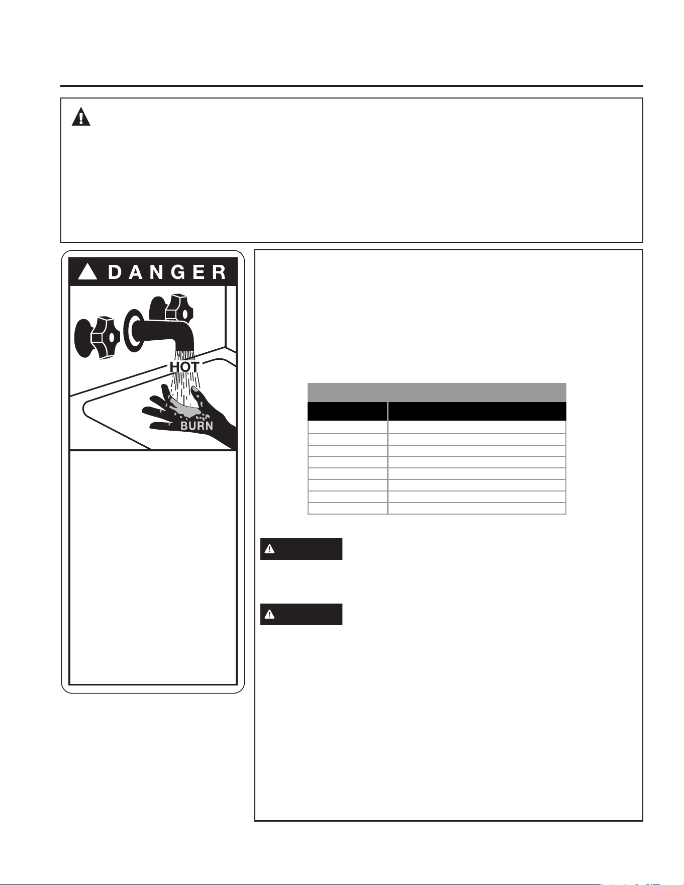
WATER TEMPERATURE ADJUSTMENT
Safety, energy conservation, and hot water capacity are factors to be
considered when selecting the water temperature setting of the water
heater. Water temperatures above 125°F can cause severe burns or death
from scalding. Be sure to read and follow the warnings outlined on the label
pictured to the left. This label is also located on the water heater near the
top of the tank.
The chart shown above may be used as a guide in determining the proper
water temperature for your home.
DANGER
There is a Hot Water SCALD Potential if the water
temperature thermostat is set too high. Households with small
children, disabled or elderly persons may require a 120°F (49°C) or
lower thermostat setting to prevent contact with “HOT” water.
WARNING
Hot water can produce 3rd degree burns in less
than 6 seconds at 140°F (60°C) and 30 seconds at 130°F (54°C).
Water delivery temperature on mixing valve models is set at a 120°F
(49°C) default temperature. Contact qualified service personnel for
adjustments, if assistance is required.
Control has been set at the factory to 120°F (49°C) to reduce the risk of
scald injury. This is the recommended starting temperature setting, but it
can be adjusted to any temperature between 100°F and 150°F (38°C and
66°C).
To Adjust the Temperature
Follow these steps:
1. Press the + or - buttons on the control panel key pad to desired
temperature.
2. Press ENTER to accept the new setting.
NOTE: To change between °F and °C, press and hold MODE.
SAFETY INFORMATION
READ AND SAVE THESE INSTRUCTIONS
IMPORTANT SAFETY INFORMATION
READ ALL INSTRUCTIONS BEFORE USING THE APPLIANCE
!
Water temperature over 125°F
(51.7°C) can cause severe burns
instantly or death from scalds.
Temperature control settings
usually approximate tap water
temperature. However, factors
could cause water temperature
to reach 160°F (71°C) regardless
of the control settings.
Children, disabled and elderly
are at highest risk of being scalded.
See instruction manual before
setting temperature at water
heater.
Feel water before bathing or
showering.
Temperature limiting valves are
available; see manual.
FOR INSTALLATIONS IN THE STATE OF CALIFORNIA
California Law requires that residential water heaters must be braced, anchored or strapped to resist falling
or horizontal displacement due to earthquake motions. At a minimum, any water heater shall be secured in
accordance with the California Plumbing Code, or modifications made thereto by a city, county, or city and county
pursuant to Section 17958.5. For the latest Installation guidelines contact: (https://www.dgs.ca.gov/DSA);
Division of the State Architect, Headquarters Office, 1102 Q Street, Suite 5100, Sacramento, CA 95811; (916)
445-8100 or call your local water heater dealer.
Applicable local codes shall always govern installation. Consult the local building jurisdiction for acceptable
bracing procedures.
120°F (49°C)
125°F (52°C)
130°F (54°C)
135°F (57°C)
140°F (60°C)
145°F (63°C)
150°F (66°C)
155°F (68°C)
Temperature
More than 5 minutes
1-1/2 to 2 minutes
About 30 seconds
About 10 seconds
Less than 5 seconds
Less than 3 seconds
About 1-1/2 seconds
About 1 second
Table courtesy of Shriners Burn Institute
Time to Produce a Serious Burn
Time/Temperature Relationship in Scalds
49-6000330 Rev. 1 5
SAFETY CONTROLS
The water heater is equipped with a combination
temperature sensor and high limit Energy-Cut-Off
control (ECO) that is located above the upper heating
element in contact with the tank surface. If for any
reason the water temperature becomes excessively
high, the high limit control (ECO) breaks the power
circuit to the heating element. Once the control opens,
it must be reset manually. Resetting of the high
limit control should be done by a qualified service
technician.
CAUTION
The cause of the high temperature
condition must be investigated by a qualified
service technician and corrective action must be
taken before placing the water heater in service
again.
CAUTION
Ensure power is completely
removed from appliance before servicing, as utility
switching devices may falsely indicate that power
has been removed.
To reset the temperature-limiting control:
1. Turn off the power to the water heater.
2. Remove the upper heating element cover and
insulation.
The thermostat protective cover should not be
removed.
3. Press the red RESET button.
4. Replace the insulation and element cover before
turning on the power to the water heater.
5. Ensure water heater is operating properly after
resetting the ECO.
IMPORTANT SAFETY INFORMATION
READ ALL INSTRUCTIONS BEFORE USING THE APPLIANCE
READ AND SAVE THESE INSTRUCTIONS
SAFETY INFORMATION
Protective
Cover
Upper Heating
Element
Cover
ECO Reset
Button

6 49-6000330 Rev. 1
Operating Instructions
Water Heater Capacity and Increasing Temperature
Setpoint (For Water Heaters without an Integrated
Mixing Valve):
The water heater temperature setting strongly impacts
the amount of usable hot water available for showers
and baths.
• Energy consumption/savings and efficiency testing of
water heaters is performed according to Department
of Energy (DOE) requirements specified at the date of
manufacture.
• Safety regulations require a factory setting no greater
than 125°F (52°C) for all new water heaters. Therefore,
if your old water heater was set to a hotter temperature
than your new water heater with a factory set setpoint of
120°F (49°C), the new water heater may seem to provide
lower capacity than your old water heater. This can be
corrected by increasing the temperature setpoint.
• If more hot water capacity is desired, increasing the
temperature from 120°F to 135°F (49°C to 57°C) will
enable the same tank of hot water to last about 25%
longer because less hot water is mixed in at the shower
or faucet.
• Increasing the water temperature setpoint may improve
the cleaning performance of dishwashers and washing
machines.
• The user can adjust the temperature setting to meet
their needs. Always read and understand the safety
instructions contained in the owner’s manual before
adjusting the temperature setpoint.
Mixing Valves
• For models with an integrated electronic mixing valve,
hot water capacity can be increased by changing
capacity selection from control, while maintaining outlet
water temperature. See page 9 for instructions to
increase hot water capacity.
• If your model does not include an integrated Electronic
mixing valve: a supplemental mixing valve for reducing
point-of-use water temperature by mixing hot and cold
water in branch water lines are commercially available.
Contact a licensed plumber or the local plumbing
authority for further information.
Extended Shutdown Periods
If the water heater is to remain idle for an extended
period of time, the power and water to the appliance
should be turned off and the water heater drained to
conserve energy and prevent a buildup of dangerous
hydrogen gas. This unit has no power button, power
can only be shut off at the circuit breaker or disconnect
switch. Unplug 120V water heater at power cord outlet
connection.
The water heater and piping should be drained if they
might be subjected to freezing temperatures.
After a long shutdown period, the water heater’s
operation and controls should be checked by qualified
service personnel. Make certain the water heater is
completely filled again before placing it in operation.
NOTE: Refer to the Hydrogen Gas Caution in the
Safety section (see page 3).
OPERATING INSTRUCTIONS
49-6000330 Rev. 1 7
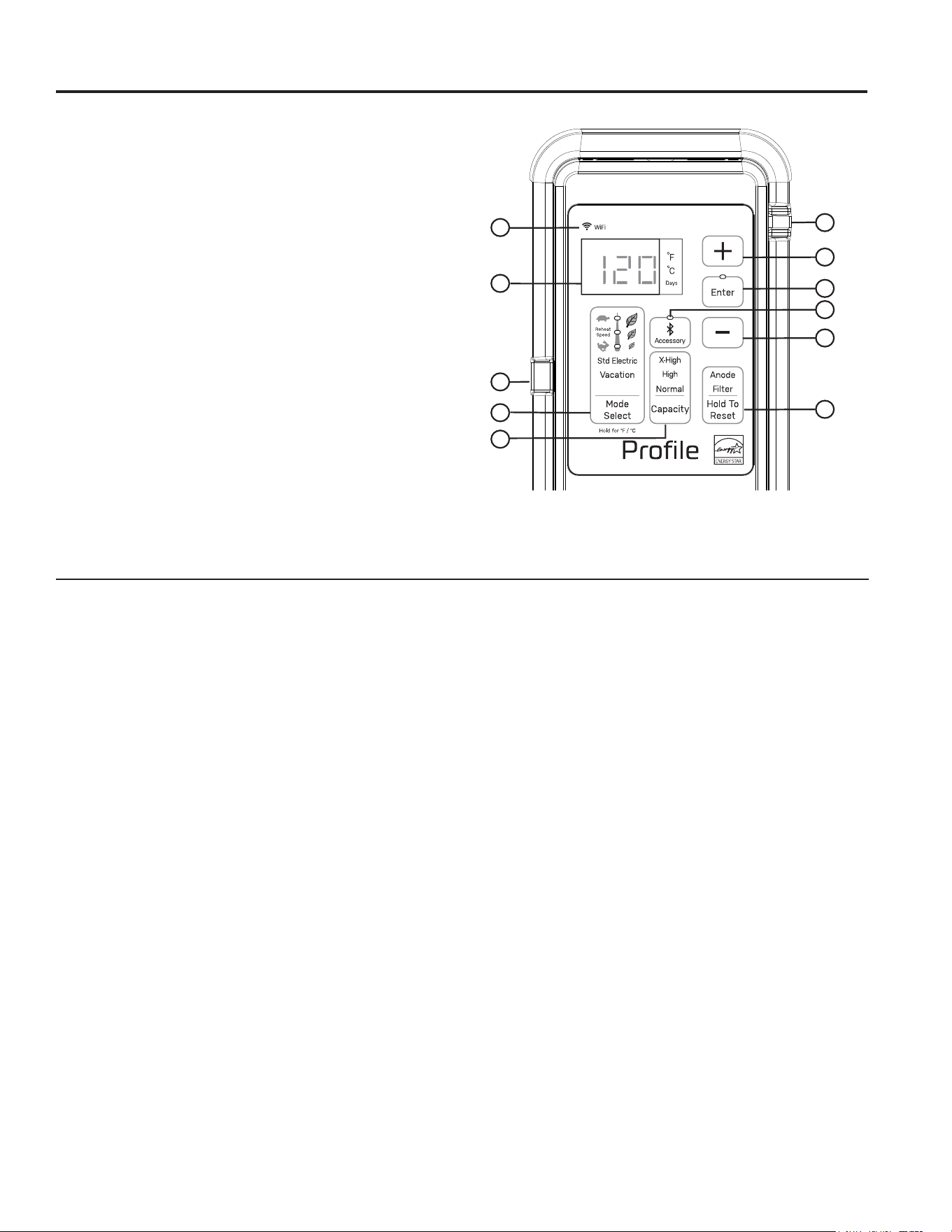
About the Control Panel
ABOUT THE CONTROL PANEL
Control Features
1. Display
2. Mode Select Button and Mode Indicator
Use this button to Select Operation Modes. Enter key
must be depressed to confirm selection.
▪ Heat Pump: Compressor ONLY (Turtle – Most
Efficient)
▪ Hybrid: Heat Pump with resistive element for
moderate reheat speed (between Turtle and Rabbit
mode)
▪ High Demand: Heat Pump with resistive elements
for faster reheat speed (Rabbit – Less Efficient)
▪ Standard Electric: Uses Electric Heating Elements
ONLY (Least Efficient)
▪ Vacation: Reduces tank temperature for select no.
of days
▪ Press and Hold to switch between °F or °C
3. Tank Capacity Selection Button and Indicator
Status (on some models)
Use this button to alternate between Normal, High
and X-High tank capacities. Enter key must be
depressed to confirm selection.
4. + Select Button
Use this button to increase the temperature setting or
vacation days.
5. - Select Button
Use this button to decrease the temperature setting or
vacation days.
6. Enter Key
Use this button to confirm temperature setting
following adjustment.
7. Dirty Filter Indicator & Reset and Anode Indicator
& Reset (if equipped)
▪ When the Filter text is illuminated, the (3) air filters
(one top and two on sides) of upper shroud require
cleaning. Press button once to silence alarm
and press and hold for 5 seconds to reset, after
cleaning.
▪ When the Anode text is illuminated and F70 fault
is displayed, the system has indicated that the
anode rod is approaching end of life and it is
recommended to replace it. Press button once
to silence alarm. Press and hold for 5 seconds
to reset the anode alarm after replacing. Call the
Installer to replace the anode rod. Contact GE
Appliances customer support at GEAppliances.com/
waterheater. Failure to replace the anode rod will
void warranty coverage and may result in a tank
leak. (See page 15 for instructions to change the
anode rod.)
8. WiFi Indicator Light
Lit when connected, flashing during configuration set
up mode.
9. Appliance Communication Module Ports (2)
For use with Service and optional accessory
modules. Visit GEAppliances.com/waterheater for
more information.
10. Bluetooth
®
Indicator for connecting Accessories
Flashes when pairing, solid when connecting.
Displaying Temperature Setpoint
The
control will display the temperature setpoint
anytime a button on the control is pressed. After 30
seconds of inactivity, the display will go blank. Note
that the Mode and Capacity selection (if equipped) will
remain illuminated in sleep mode. To wake the control
at any time to see the temperature setpoint, press any
button on the control.
Turning on the Water Heater
There is no power button for this unit. Once the water
heater is wired and power is supplied, it will be on. The
display will show the current water temperature setting.
To comply with safety regulations, the controls are factory
preset to 120°F (49°C).
To Adjust the Temperature
Follow these steps:
1. Press the + or - button on the control panel key pad
to desired temperature.
2. Press ENTER to accept the new setting.
NOTE: To change between °F and °C, press and hold
the Mode Select button.
4
6
5
10
7
9
8
1
2
3
9
Appearance may vary according to specific model.
8 49-6000330 Rev. 1
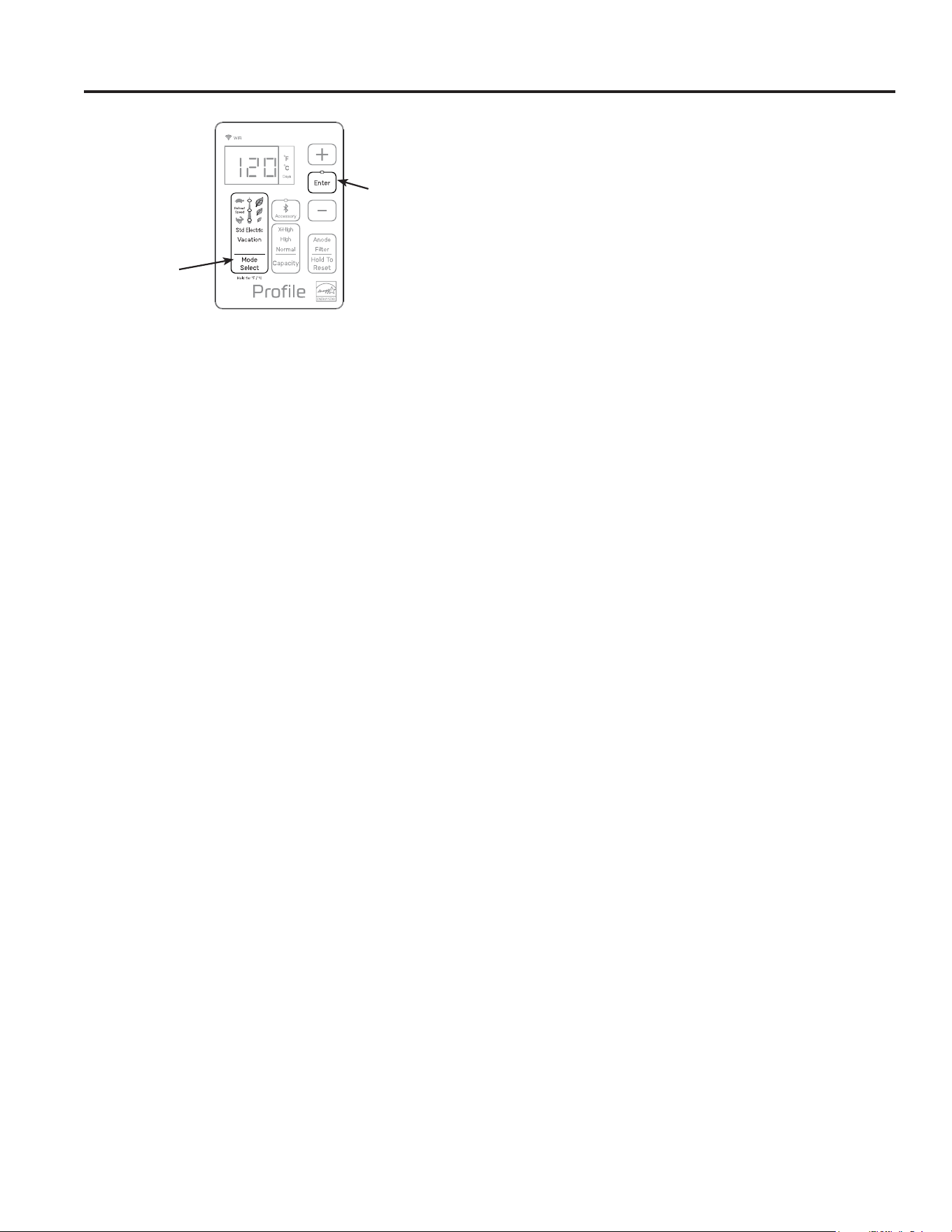
Operation Modes
OPERATION
This water heater defaults to the Hybrid operating mode.
To select available modes listed below:
▪ Press the MODE button until the LED next to the
desired Operating Mode is illuminated.
▪ For Hybrid and Heat Pump (Turtle) mode, Press “Enter”
to activate selected mode.
▪ For High Demand Mode (Rabbit), Std Electric and
Vacation Mode, Input the total days to remain in Mode
by pressing + or - and then Press “Enter” to activate
selected mode and operating days.
Note limitation of operating days in each mode as
follows:
▪ High Demand (Rabbit): Default is 3, with a max.
of 99 days.
▪ Std Electric: Default is 3, with a max. of 99 days.
▪ Vacation: Default is 7, up to 199.
In Heat Pump (Turtle), Hybrid or High Demand (Rabbit)
Mode, the corresponding Mode LED will flash anytime
the heating elements are active, such as during the initial
recovery from a large draw. This is normal and does
not indicate an operating issue. The Display will toggle
between the days remaining and the temperature set
point in High Demand (Rabbit), Std Electric and Vacation
Modes.
Cold Climate Efficiency
This heat pump water heater is compliant with the
Northwest Energy Efficiency Alliance Advanced Water
Heater Specification (latest 8.1 version , active at time
of product listing), and may qualify for rebates in some
regions. Check with your local utility for available rebates
and requirements.
A ducting kit is available for use with your heat pump
water heater if desired. [See GEAppliances.com for
ducting kit details].
Ducting kits may be installed to achieve directed flow
of inlet and outlet air for heat pump operation, or to
allow water heater installation in rooms less than 700cu.
ft.(19.8 cu.m.) or without louvered doors, as specified in
the installation instructions.
Heat Pump Mode (Turtle LED) —
RECOMMENDED FOR MAXIMUM SAVINGS
Heat Pump is the most energy-efficient mode for this
water heater. It takes heat from the surrounding air to
heat the water. The time it takes to heat the water is
longer in this mode, so it may not be sufficient if you
have a high-demand situation such as a large household
or company.
Hybrid Mode (LED between Turtle and
Rabbit)
Hybrid mode combines the energy efficiency of Heat
Pump with the recovery speed and power of the Electric/
Standard mode in most water usage situations. Hybrid
mode will allow the unit to perform like a standard
electric water heater while providing significant energy
savings.
NOTE: Energy Guide unit performance, energy
consumption and savings are based on non-ducted
installations in Hybrid mode at required Department of
Energy (DOE) test conditions. Operating in Heat Pump
mode may provide a greater savings in energy and
operating costs than the claimed savings.
High Demand Mode (Rabbit LED)
This mode may be necessary if your household has
a higher-than-average water usage or the unit is
undersized for the household water demands. In this
mode, the unit will use the electric heating elements only
when the water demand rate is high. When using the
heating elements, the water temperature will recover at
a faster rate but it will use more energy to heat it. Unlike
Electric/Standard mode, it will use the heating elements
only when needed, and use the heat pump when water
demand rates are lower.
NOTE: The difference between Hybrid mode and High
Demand mode is that in High Demand mode the heating
resistive elements are activated sooner than in Hybrid
mode. At the end of the selected time period, the unit
will switch back to the previously selected more energy-
efficient mode.
Standard Electric Mode
This mode uses only the upper and lower heating
resistance elements to heat the water, stopping the cool
air discharge during heat pump operation. The time it
takes to heat the water is less in this mode, but it is the
LEAST energy-efficient mode.
At the end of the selected time period, the unit will switch
back to the previously selected more energy-efficient
mode.
Confirm by
pressing Enter
Press
Mode Select
49-6000330 Rev. 1 9
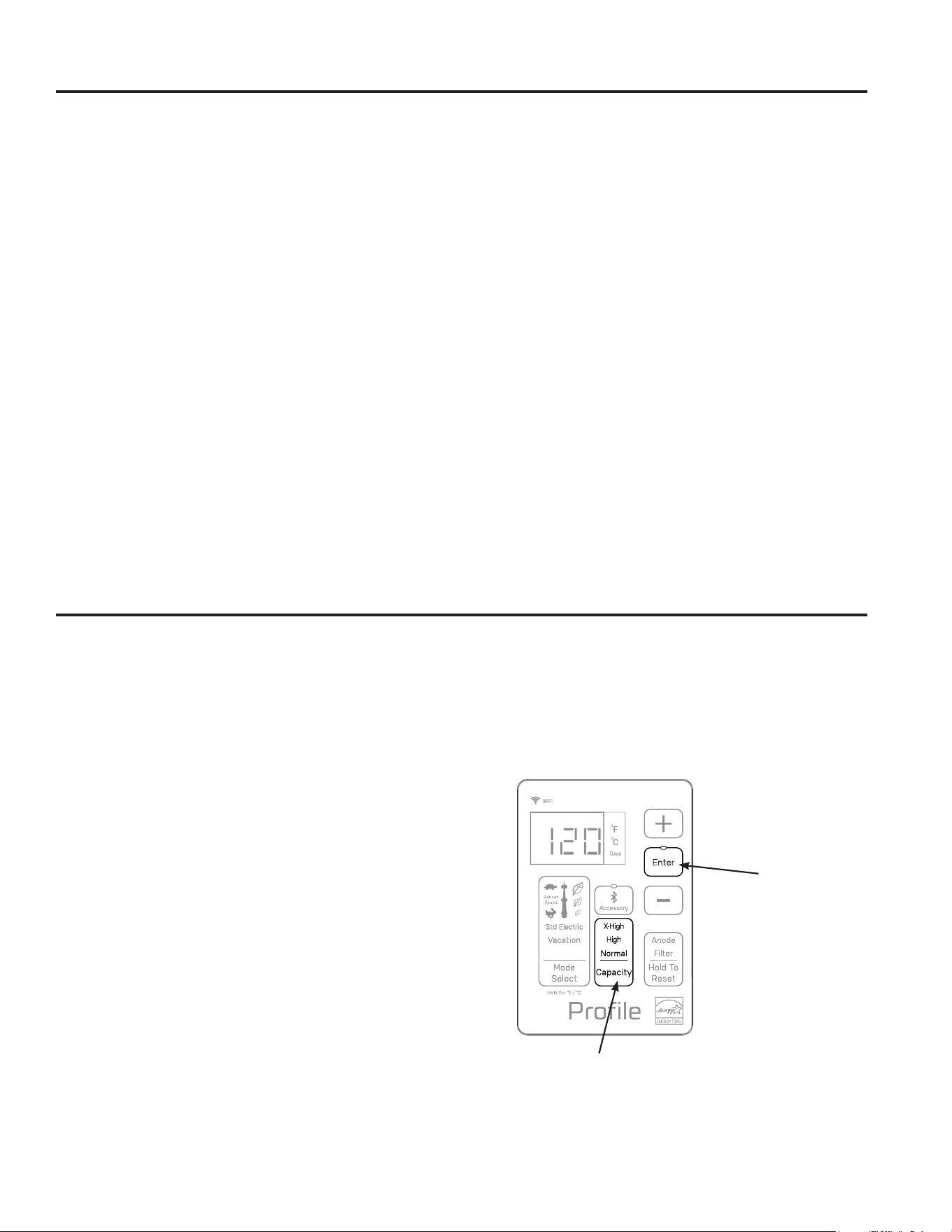
Operation Modes
When activated this feature stores water at higher
temperatures. As hot stored water leaves the tank, cold
water is mixed in to maintain the desired set point. This
mixing allows more usable hot water to be available.
The water heater defaults to Normal hot water Capacity
setting, which is used to calculate annual operating cost,
(and a 125F outlet water setting).
To change tank Capacity setting:.
1. Press the “Capacity” button until High, X-High or
Normal text is illuminated.
2. Confirm selection by pressing “Enter” key.
Capacity Options (based on 120°F default outlet water
temperature setting and 58°F inlet water temperature):
Normal: No increase of hot water capacity from outlet
water setting
High: Increases hot water capacity up to 40%
X-High: Increases hot water capacity up to 60%
Hot Water Flexible Capacity Selection (on some models)
OPERATION
Vacation Mode
This feature is recommended when you will be away from
the home for an extended period of time and hot water is
not needed. In this mode, the unit will reduce the water
temperature setting to 50ºF (10°C) and will use the most
efficient heating mode to conserve energy while the heater
is sitting idle. The unit will automatically resume heating
one day before your return, so that hot water will be
available.
For example, if you will be gone 14 days, set Vacation
mode for 14 days using the steps above. The temperature
setting will automatically reduce to 50°F (10°C) for 13
days. At the end of the 13th day, the previous operating
mode and temperature setting will reset to ensure hot
water is available upon your return.
Extended Shutdown Periods
If the water heater is to remain idle for an extended period
of time, the power and water to the appliance should be
turned off and the water heater drained to conserve energy
and prevent a buildup of dangerous hydrogen gas. This
unit has no power button, power can only be shut off at the
circuit breaker or disconnect switch.
If the water heater has an anode depletion sensing feature
(some models) and the water heater cannot be drained,
it is recommended to leave the power turned on with the
water heater in vacation mode to ensure that the feature
will continue to operate properly while still conserving
energy.
The water heater and piping should be drained if they
might be subjected to freezing temperatures.
After a long shutdown period, the water heater’s operation
and controls should be checked by qualified service
personnel. Make certain the water heater is completely
filled again before placing it in operation.
NOTE: Refer to the Hydrogen Gas Caution in the
Safety section (see page 3).
Confirm by
pressing Enter
Press Capacity
10 49-6000330 Rev. 1
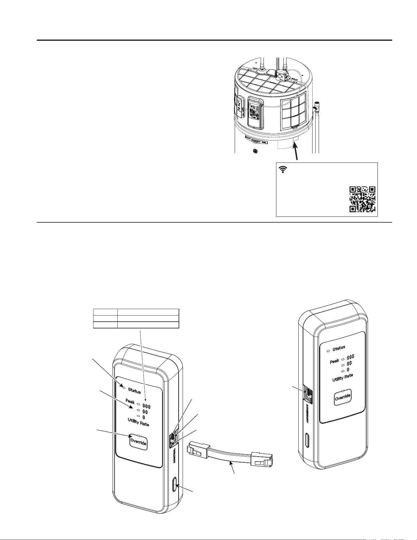
Appliance Communication
GE Appliances WiFi Connect
GE Appliances WiFi Connect Enabled*
If your
water heater has a Connected Appliance Information
label located to the right of rating plate as shown, your
model is GE Appliances WiFi Connect Enabled.
A WiFi communication card is built into the product
allowing it to communicate with your smart phone for
remote monitoring, control and notifications. Please
visit GEAppliances.com/connect to learn more
about connected appliance features, and to learn what
connected appliance apps will work with your smart
phone.
*Select models only
CTA-2045 Module
The CTA-2045 is connected to a compatible GE Water
Heater’s Control Panel, and a module (provided by the
local utility company) can be plugged into the bottom of
the CTA-2045, enabling direct utility signals through 5G,
Wi-Fi, or other communication pathways. Once connected
and set up, the CTA-2045:
• indicates the local utility’s current rate tier;
• initiates the water heating cycle at times agreed by the
consumer and utility company, enabling the water heater
to run at the most convenient and least costly times; and
• allows the consumer to temporarily override time-of-use
schedules or utility signals.
APPLIANCE COMMUNICATION
Contains/Contient FCCID: ZKJ-WCATA008
Contains/Contient IC: 10229A-WCTA008
UPD ID: XX-XX-XX-XX-XX
MAC ID: XX-XX-XX-XXXXXXXX
184D2604P002
Connected Appliance Information
Informations sur l’électroménager connecté
Scan for App
Rechercher Appli
Meets ANSI/CTA-2045 standard
when equipped with GEA module
Conforme à la norme ANSI/CTA-2045
lorsqu’il est équipé d’un module GEA
Status LED indicates
time-of-use schedule
and module are
operating
3 LEDs indicate
current utility rate
(see table above)
RJ45 Cable
RJ45 control port
Push Buttons
(1 on each side) to
open Front Cover
Yellow LED indicates
communication in process
Green LED indicates
software functioning
RJ45 Accessory
Port
PEAK $$$ Utility rates are at a premium.
$$ Normal/No Rate Control.
$ Utility rates lower than normal.
Override
time-of-use schedules
or utility signals
49-6000330 Rev. 1 11
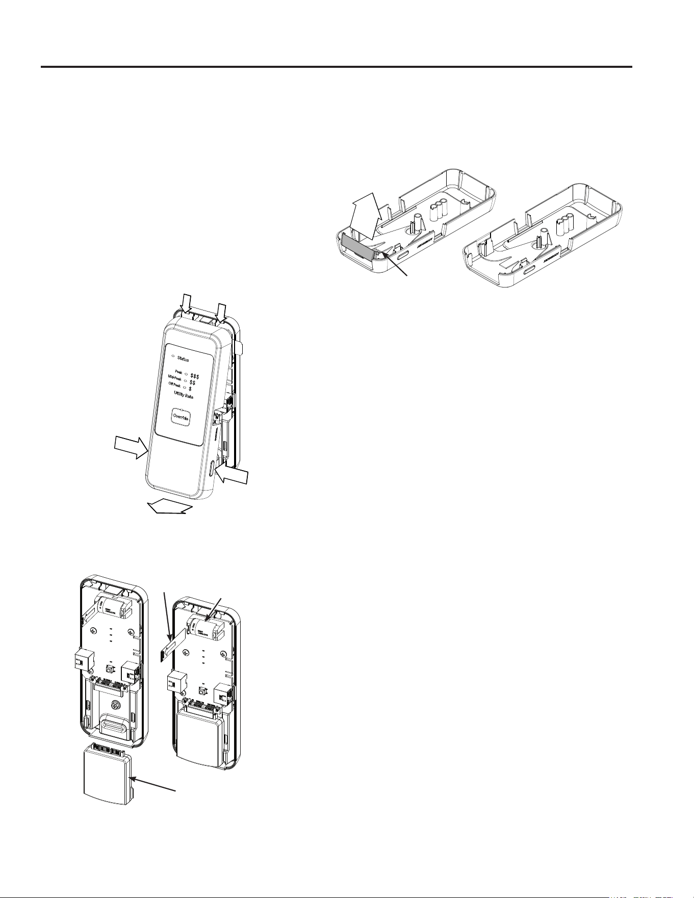
CTA-2045 Module (Cont.)
Initial Setup
1. Ensure that the water heater is fully installed, filled
with water and functioning.
2. Confirm that the RJ45 cable is securely connected to
both the CTA-2045 and Water Heater Control.
3. Download the SmartHQ™ App on your smartphone.
4. Follow SmartHQ™ App instructions to connect your
Water Heater.
5. Follow instructions in the SmartHQ™ App for setting
up optional time-of-use schedules.
6. Remove the Front Cover.
7. Plug in the module (provided by 3rd party) at the
bottom of the CTA-2045. NOTE: If installing without
module, skip to next step.
8. Remove the Battery Isolator Pull Tab to activate
the battery and initiate clock function (see previous
illustration).
NOTE: Some Utility Modules may require modification of
the bottom of the CTA-2045 Front Cover.
9. Reattach the Front Cover of the CTA-2045.
10. Follow the 3rd party module instructions to ensure
functionality and connectivity.
11. Conform that the status LED on the CTA-2045 is
illuminated, as well as one of the three utility Rate
LEDs. Both the Status LED and one Utility Rate LED
will be illuminated when the CTA-2045 is functioning
normally.
Override Button
To override time-of-use schedules or utility signals,
press the Override Button. The Override LED will blink
continuously to indicate that the function is active. The
Override function will remain active for 24 hours or until
the Override Button is pressed again.
Power Outage
During a power outage, the CTA-2045 will transition to
battery power, ensuring that the clock and time-of-use
schedules are preserved.
NOTE: If the Override function was active at the time
of the power outage, it will reactivate when power is
restored
Appliance Communication
APPLIANCE COMMUNICATION
1. Lift
2. Cut and Remove
2. Pull Down
3. Pull Out
1. Push Buttons
Module
Replaceable CR2
Battery
Battery Isolator
Pull Tab
12 49-6000330 Rev. 1
Routine Preventive Maintenance
DANGER
Risk of Scald - Before manually
operating the relief valve, make certain no one will
be exposed to the danger of coming in contact with
the hot water released by the valve. The water may
be hot enough to create a scald hazard. The water
should be released into a suitable drain to prevent
injury or property damage.
NOTE: If the temperature and pressure-relief valve
on the hot water heater discharges periodically, this
may be due to thermal expansion in a closed water
system. Contact the water supplier or your plumbing
contractor on how to correct this. Do not plug the
relief valve outlet.
Properly maintained, your water heater will provide years
of dependable trouble-free service. It is suggested that
the following annual preventive maintenance program be
established.
1. Inspect Temperature & Pressure Relief Valve.
2. Inspect heating elements, ECO, and wiring to each.
3. Drain and Flush the water heater tank.
4. Anode rod must be removed and inspected.
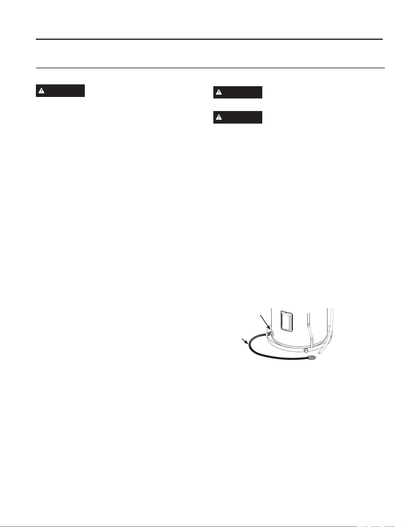
Temperature and Pressure-Relief Valve:
Once a year, it is recommended to lift and release the
lever handle on the temperature and pressure-relief
valve, located on the front-right side of the water heater,
to make certain the valve operates freely. Allow several
gallons to flush through the discharge line to an open
drain.
Heating Elements and ECO:
Once a year, it is recommended to inspect the heating
elements, high limit Energy-Cut-Off (ECO) control,
and wiring to each. Inspection should be completed by
service personnel qualified in electrical appliance repair.
Most electrical appliances, even when new, make some
sound when in operation. If the hissing or singing sound
level increases excessively, the electric heating element
may require cleaning. Contact a qualified installer or
plumber for inspection.
Draining and Flushing the Water Heater
CAUTION
Risk of Shock - Shut off power to
the water heater before draining water.
DANGER
Risk of Scald - Before manually
operating the relief valve, make certain no one will
be exposed to the hot water released by the valve.
The water drained from the tank may be hot enough
to present a scald hazard and should be directed to
a suitable drain to prevent injury or damage.
A water heater’s tank can act as a settling basin for
solids suspended in the water. It is therefore not
uncommon for hard water deposits to accumulate in the
bottom of the tank. To clean the tank of these deposits,
it is recommended to drain and flush the water heater
tank once a year. To drain the water heater, follow these
steps:
1. Turn off power to the unit. The electric heating
elements will become damaged if operated without
water.
2. Attach a garden hose to the drain valve located at the
bottom of the unit and direct that hose to a drain.
3. Turn off the cold water supply.
4. Admit air to the tank by opening a hot water faucet or
lifting the handle on the relief valve.
5. Open the drain valve. Use a flat blade screwdriver to
turn stem of drain valve.
Flushing the Tank:
1. Follow steps above to drain the water heater.
2. Once the water heater is empty, with the drain valve
open and garden hose attached to the drain valve,
turn on the cold water supply.
3. Allow several gallons to flush through the drain valve
and hose to an open drain.
4. Turn off the water supply and allow any water
remaining in the tank to drain.
5. Repeat steps 3 and 4 until water runs clear.
6. Close the drain valve and fill the tank before returning
power to the unit. The tank is full when water runs out
of a nearby open hot water faucet.
Flushing should be done with an empty tank to promote
additional removal of sediment.
Care and Cleaning
Exterior Surfaces
Hand wash with damp cloth, using only warm water. Wipe dry using a dry, clean cloth.
CARE AND CLEANING
Brass Drain
Valve
Hose
49-6000330 Rev. 1 13
Cleaning the Filters
In the Hybrid, Heat Pump, and High Demand modes, the
water heater pulls air through the 3 filters and out the back
of the unit. The filters are in place to protect the evaporator
from dirt and dust.
Clean air filters are important to get the highest efficiency.
Occasionally these filters will need to be cleaned. When the
filters require cleaning, the Filter LED will illuminate and an
alarm will sound.
NOTE: If the filters gets too dirty, the unit will automatically
switch to Standard Electric mode and energy savings will
be lost.
Leave the power on. Remove the filter from the top of the
unit and the (2) filters from the side of the unit. Once they
have been removed, the filters can be vacuumed or wiped
clean with a damp cloth or rinsed with warm water.
Once the filters have been cleaned and dried, they can be
replaced by aligning with the shroud and snapping in place
by pushing at embossed locations on filters as shown in
illustration.
After the clean filters have been reinstalled, press and
hold the Reset button (below the FIlter LED), until the
Filter LED turns OFF. The unit will automatically revert
to the previously selected operating mode. If a heating
cycle is active when the filter alarm is reset, it will continue
in Electric/Standard mode to finish the cycle, then
automatically revert to the previously selected mode.
IMPORTANT: Filters must be cleaned when the alarm is
displayed. A dirty filter will make the system work harder
and result in a reduction of efficiency and possible damage
to the system. In order to get the best energy efficiency
available, make sure your filters are clean.
NOTE: If the dirty filter alarm returns within a few days
after cleaning and resetting, it may be an indication of a
refrigerant leak. Further diagnosis by a service technician is
necessary.
CARE AND CLEANING
Care and Cleaning
Clearing the Condensation Drain Tube
The main drain is intended to carry all condensate away. If
it is clogged, the heat pump will stop operating, the display
will show F73, and an alarm will sound. Press any button
to silence the alarm, then clear the condensate drain by
removing any drain lines and connections, and clearing
debris. Reattach drain lines and connections, then allow
the water heater to run. The GeoSpring water heater will
continue to produce hot water using the backup resistance
heating elements until the condensate drain has been
cleared, and is able to drain properly. Once the drain has
been cleared, the unit will then be able to operate the heat
pump again.
Periodically inspect
the drain lines and
clear any debris that
may have collected
in the lines.
See Installation
Instructions for more
information.
Water Leak Notification & Reopening
Shut-Off Valve
When the sensor detects a water leak (H20 is shown
on display), an audible alert will sound, and a leak alert
notification will be sent to your mobile device (when
connected to the SmartHQ App). If a smart water shut-off
valve is installed, it will stop any new water from being
supplied to the water heater and display will toggle between
“Off” and “H20”. To clear the leak alert, remove the sensor
from the leak source and dry sensor. The display will stop
showing “H20” and “Off” and the valve will open, restoring
water flow to the water heater.
(3) Filters
Push at (6) embossed
locations to re-snap
filters in place.
Push at (8)
embossed
locations to
re-snap filters
in place.
Direct the
main drain
line into a
drain
Drain Line
Connection
Overflow
14 49-6000330 Rev. 1
Anode Rod
Anode rods are designed and installed to protect and
extend the life of residential water storage tanks.
The anode rod must be removed from the water heater’s
tank and inspected annually, and replaced when more
than 6” (15.2 cm) of core wire is exposed at either end of
the rod.* NOTE: Artificially softened water will cause the
anode rod to consume more rapidly.
Due to shock hazard and to prevent accidental water
leaks, this inspection should be done by a qualified
servicer or plumber, and requires that the electric power
and cold water supply be turned off before servicing the
anode rod.
NOTICE: Do not remove the anode rod from the water
heater’s tank except for inspection and/or replacement,
as operation with the anode rod removed will shorten
the life of the glass-lined tank and will void warranty
coverage.
Some areas have water conditions that may cause
an odor to develop in the water heater. Special alloy
replacement rods are available to address this condition.
*NOTE: Failure to replace the anode rod when
consumed voids the warranty for the tank. Warranty
coverage for all other components remains intact,
and is unaffected by this maintenance requirement.
The replacement anode rod, and the inspection for
consumption are not covered by warranty.
Additional information for models with an
anode depletion sensing feature (Anode
LED on the control, on equipped models):
When the depletion-sensing anode rod nears
end of life, the ANODE text will illuminate and
the control will beep and display F70. When
this occurs, the anode rod must be inspected
and replaced if the core wire at the top of the anode rod is
exposed.* It is recommended to replace the anode rod as
soon as possible to ensure that the tank will continue to be
protected from corrosion. Call installer/servicer to order or
to replace the anode rod. (See page 15 for instructions to
change the anode rod.)
Press the Anode “Hold To Reset” button (below the Anode
LED) once to silence the alarm. Once replaced, reset the
alarm by pressing and holding the “Hold To Reset” button
for 5 seconds until the control beeps and the Anode LED
will turn off.
If special alloy anode rod is installed to address a water
odor condition, the anode depletion sensing feature must
be disabled. If disabled, annual inspections of the anode
rod are required since the water heater will no longer be
capable of alerting for a depleted anode rod.
To disable the feature:
1. Upon power-up following a special alloy anode rod
installation, the control will sound an alarm and F41 will
display. Press the Anode “Hold To Reset” button to quiet
the alarm.
2. Press the Anode “Hold To Reset” button 3 times. “Off”
or “On” will display confirming that the feature has been
disabled/ enabled.
To enable the feature if a new anode depletion sensing
anode rod is installed, follow Step 2 above.
NOTE: If the display is blank, press any button to wake the
control before entering a button combination.
NOTE: If the water heater has been installed with a
device that periodically cuts power to the water heater, the
accuracy of the anode rod depletion sensing feature may
become compromised and anode rod inspection every 2-3
years is required.
If the water heater will be inactive for a long period of time
and the water heater cannot be drained, it is recommended
to leave the power turned on with the water heater in
vacation mode to ensure that the feature will continue to
operate properly while still conserving energy.
NOTE: Refer to the Hydrogen Gas Caution in the Safety
section (see page 3).
Anode Rod Maintenance and Service
Routine Preventative Maintenance
CARE AND CLEANING
49-6000330 Rev. 1 15
Anode Rod Maintenance and Service
Tools needed:
• Phillips Screwdriver
• Socket Wrench
• Socket Extension(s) ~15” long
• 1
1
/16” Socket
• Softset Sealant
• Anode Rod, if needed
* See page 36 for part ordering instructions
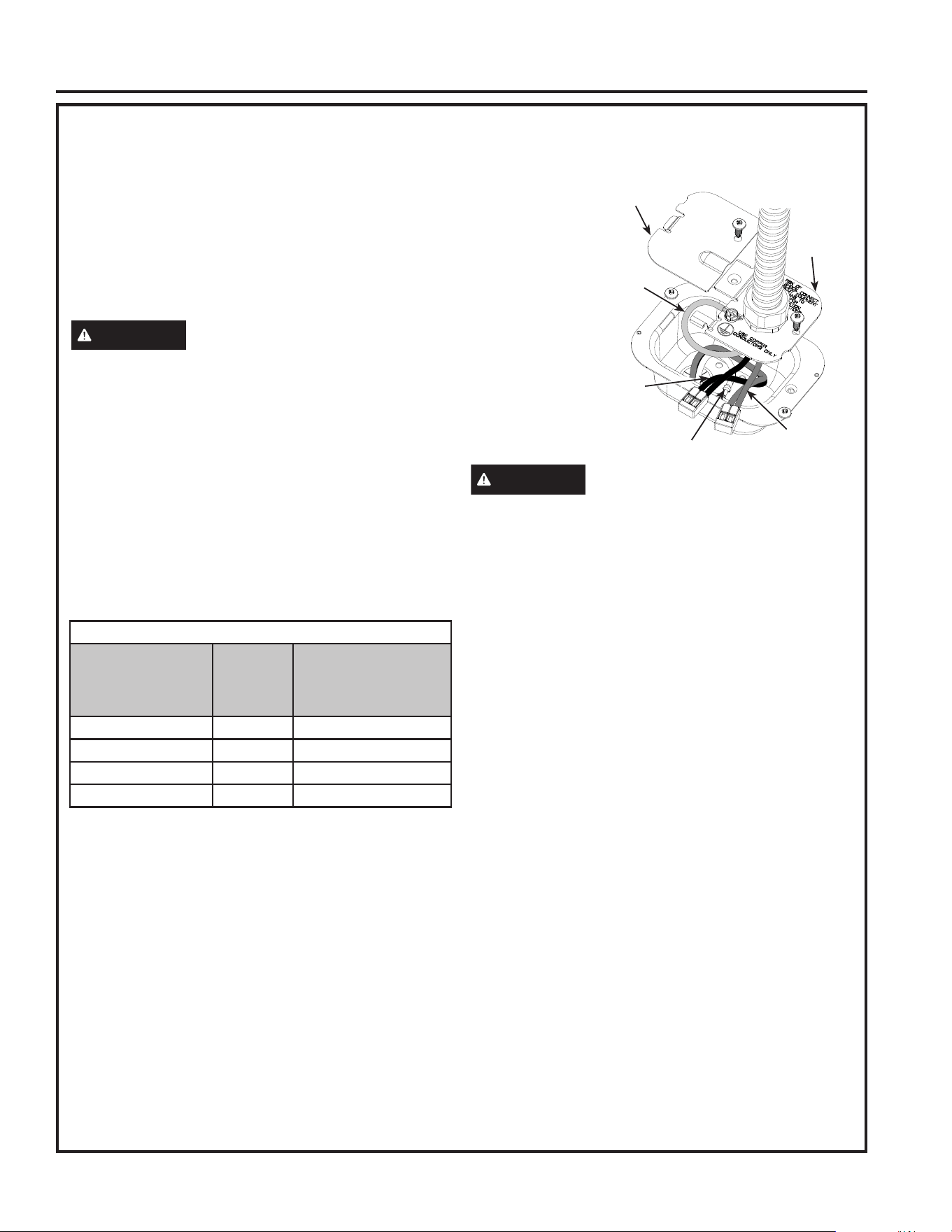
To service the Anode Rod:
1. Disconnect power, shut off the water supply, and
partially drain one or two gallons from the water
heater through the lower drain valve.
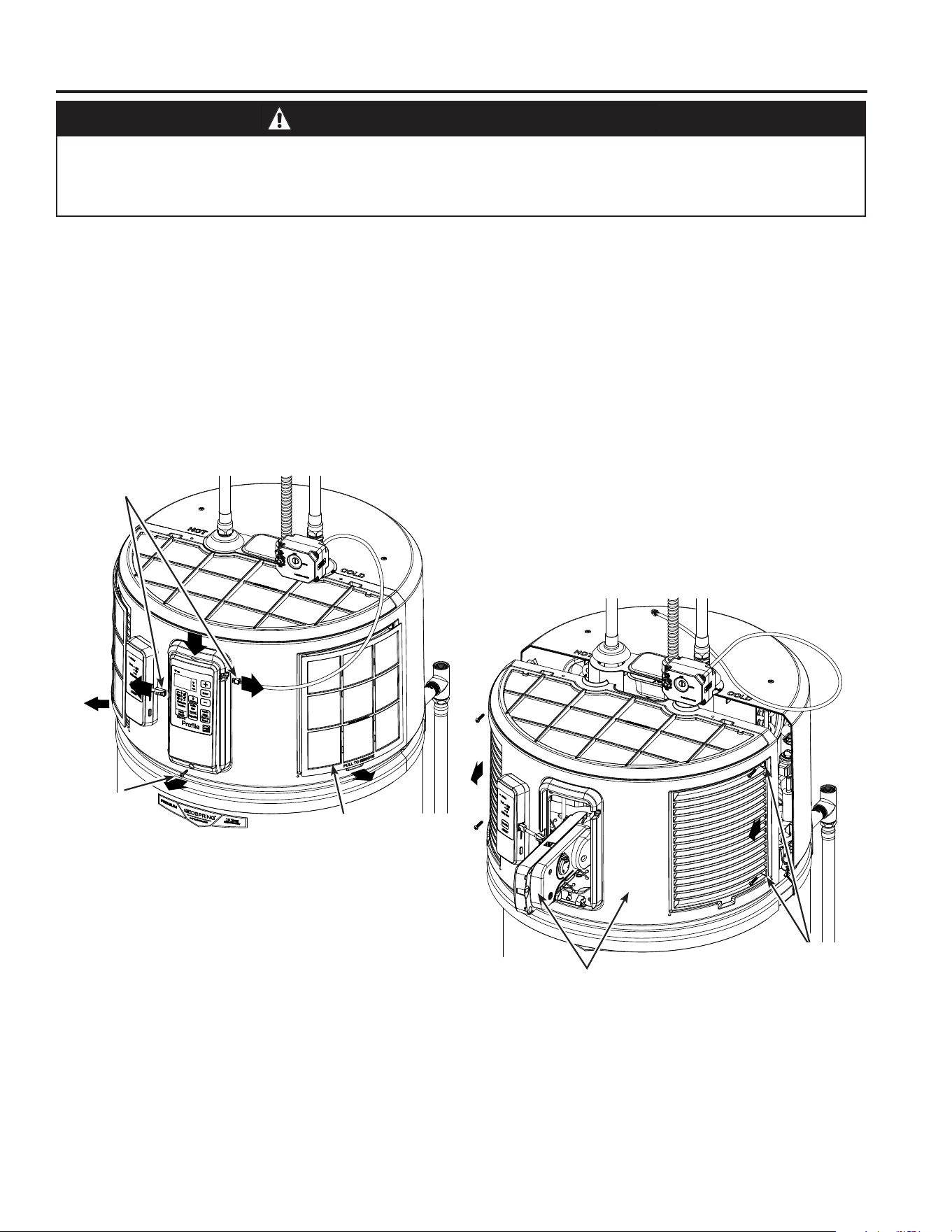
2. Remove the (2) side filters from the front shroud and
disconnect the (2) RJ45 connectors from the control
housing.
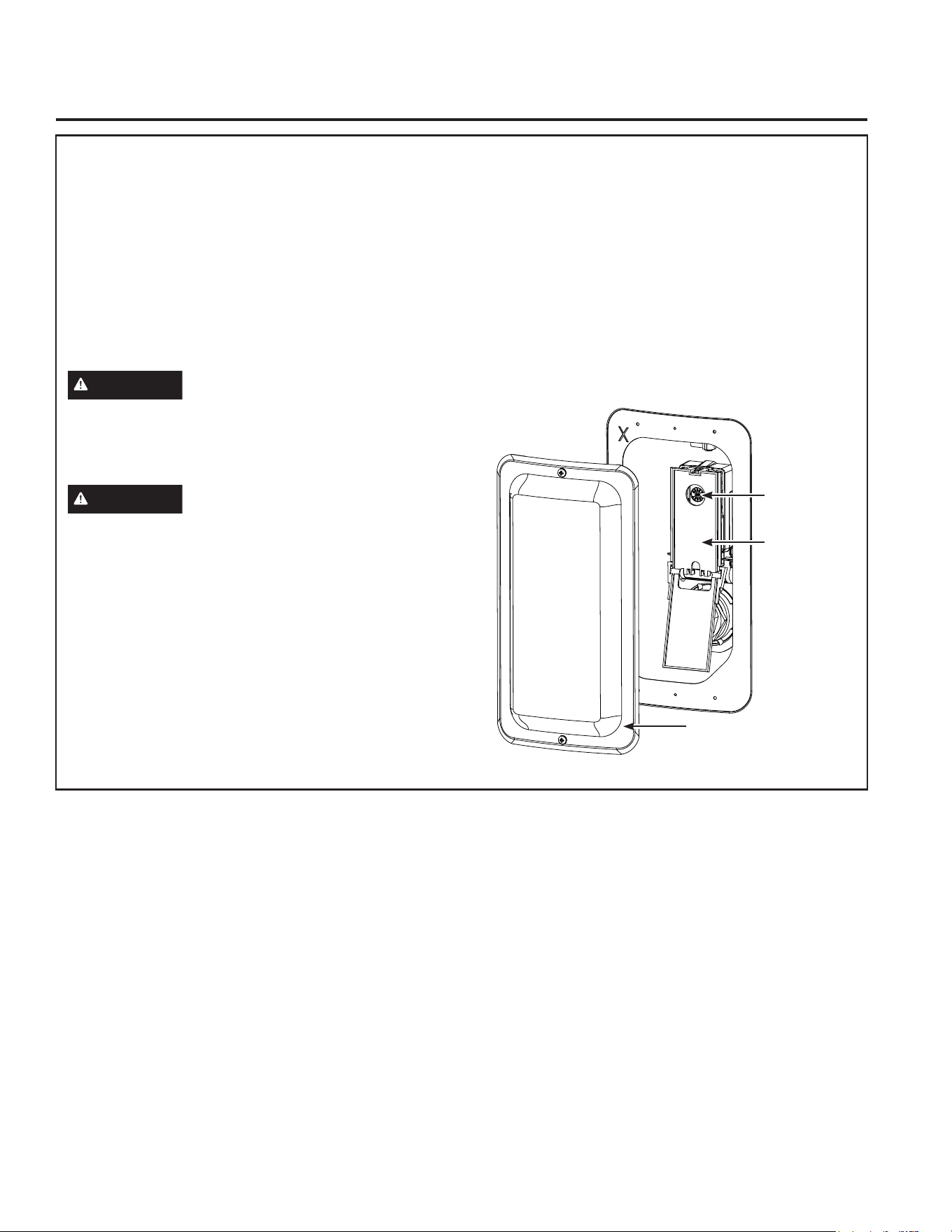
3. Remove the front shroud using following steps
A. Remove Phillips-head screw under control
housing.
B. Pull the control housing assembly down and rotate
outward at bottom to release from mounting frame.
C. Remove the (4) Phillips-head screws beneath the
left and right-side filter locations.
D. Pull front shroud away from rear shroud, while
sliding control housing through opening, without
disturbing wire connections.
4. If present, remove insulation to uncover the anode rod
as shown in illustration. Unplug anode wire (on some
models).
This information is intended to use by individuals possessing adequate background of electrical, electronic
and mechanical experience. Any attempt to repair a major appliance may result in personal injury and property
damage. The manufacturer or seller cannot be responsible for the interpretation of this information, nor can it
assume any liability in connection with its use.
CARE AND CLEANING
Remove (4)
Phillips-head
screws (each
side)
Remove front shroud,
while leaving control
housing connected to
wiring.
CAUTION - IMPORTANT SAFETY NOTICE
Remove (2) RJ45
Connectors
Remove (1)
Phillips-head
screw
Pull Left and Right-
side Filters from
bottom slot
16 49-6000330 Rev. 1
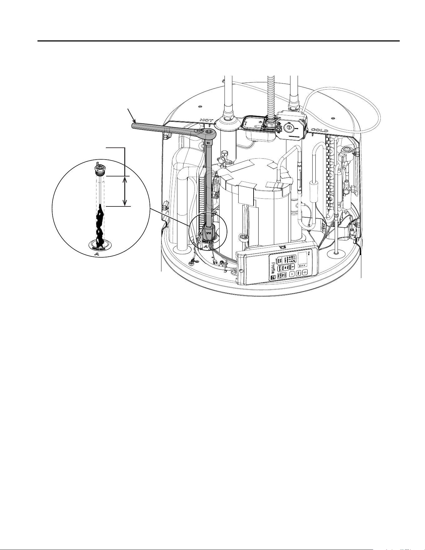
5. Using a 1
1
/16” socket and extension (while avoiding contact with tubing and components), unscrew the anode rod,
then lift out to inspect as shown in illustration. If more than 6” of core wire is exposed, the anode rod should be
replaced. If the anode rod has not been depleted, reinstall it into the water heater following steps 6-7 below.
6. To install the anode rod, seal the threads with soft set sealant, thread into the port and using the torque wrench
tighten to 50 ± 5 ft-lbs of torque. Plug in the wire for the anode rod (some models). If an Aluminum-Zinc or other
non-sensing anode rod is installed, the anode depletion sensing feature must be disabled and the wire end taped
(some models).
7. Turn water supply on, open a tap to remove any air in plumbing system, inspect for leaks, then reassemble the
unit in reverse order, and turn the power on. Reset the ANODE button (some models) by pressing and holding for
10 seconds to indicate that a new anode depletion sensing anode rod is installed.
Anode Rod Maintenance and Service (Cont.)
CARE AND CLEANING
Replace anode
rod if more than 6”
(15.2 cm) of core
wire exposed.
Socket/wrench
& extension
Anode Rod fitting & wire
connection in recessed
pocket
49-6000330 Rev. 1 17
WARNING
• Do not use means to accelerate the defrosting process or to clean, other than those recommended by the
manufacturer.
• The appliance shall be stored in a room without continuously operating ignition sources (for example: open
flames, an operating gas appliance or an operating electric heater.
• Do not pierce or burn.
• Be aware that refrigerants may not contain an odor.
Warning; Flammable Materials. A2L refrigerant per ISO 817
Owner’s Manual; Operating Instructions
Read Owner’s Manual
Service Indicator; Read Technical Manual
General
– Handling, installation, cleaning, servicing and disposal of refrigerant must comply with the local regulation and
the instruction.
– Servicing shall be performed only as recommended by the manufacturer.
Requirements for Operation, Service and Installation of Appliances Using
Flammable Refrigerants
REQUIREMENTS FOR OPERATION
REQUIREMENTS FOR OPERATION

18 49-6000330 Rev. 1
REQUIREMENTS FOR OPERATION
Requirements for Operation, Service and Installation of Appliances Using
Flammable Refrigerants
Qualification of workers
Every working procedure that affects safety means shall only be carried out by competent persons.
Examples for such working procedures are:
• breaking into the refrigerating circuit.
• opening of sealed components.
The competent persons are trained by the national training organisations or manufacturers that are accredited
to teach the relevant national competency standards that may be set in legislation. The achieved competence
should be documented by a certificate.
Information on servicing
Prior to beginning work on systems containing FLAMMABLE REFRIGERANTS, safety checks are necessary to
ensure that the risk of ignition is minimized. For repair to the REFRIGERATING SYSTEM, the below requirement
shall be completed prior to conducting work on the system:
– Work shall be undertaken under a controlled procedure so as to minimise the risk of a flammable gas or vapour
being present while the work is being performed.
– All maintenance staff and others working in the local area shall be instructed on the nature of work being
carried out. Work in confined spaces shall be avoided.
– The area shall be checked with an appropriate refrigerant detector prior to and during work, to ensure the
technician is aware of potentially toxic or flammable atmospheres. Ensure that the leak detection equipment
being used is suitable for use with all applicable refrigerants, i. e. non-sparking, adequately sealed or
intrinsically safe.
– If any hot work is to be conducted on the refrigerating equipment or any associated parts, appropriate fire
extinguishing equipment shall be available to hand. Have a dry powder or CO2 fire extinguisher adjacent to the
charging area.
REQUIREMENTS FOR OPERATION

49-6000330 Rev. 1 19
REQUIREMENTS FOR OPERATION
REQUIREMENTS FOR OPERATION
Requirements for Operation, Service and Installation of Appliances Using
Flammable Refrigerants
Information on servicing (cont)
– No person carrying out work in relation to a REFRIGERATING SYSTEM which involves exposing any pipe work
shall use any sources of ignition in such a manner that it may lead to the risk of fire or explosion. All possible
ignition sources, including cigarette smoking, should be kept sufficiently far away from the site of installation,
repairing, removing and disposal, during which refrigerant can possibly be released to the surrounding space.
Prior to work taking place, the area around the equipment is to be surveyed to make sure that there are no
flammable hazards or ignition risks. “No Smoking” signs shall be displayed.
– Ensure that the area is in the open or that it is adequately ventilated before breaking into the system or
conducting any hot work. A degree of ventilation shall continue during the period that the work is carried
out. The ventilation should safely disperse any released refrigerant and preferably expel it externally into the
atmosphere.
– Where electrical components are being changed, they shall be fit for the purpose and to the correct
specification. At all times the manufacturer’s maintenance and service guidelines shall be followed. If in doubt,
consult the manufacturer’s technical department for assistance.
– The following checks shall be applied to installations using FLAMMABLE REFRIGERANTS:
• Marking to the equipment continues to be visible and legible. Markings and signs that are illegible shall be
corrected.
– Repair and maintenance to electrical components shall include initial safety checks and component inspection
procedures. If a fault exists that could compromise safety, then no electrical supply shall be connected to
the circuit until it is satisfactorily dealt with. If the fault cannot be corrected immediately but it is necessary to
continue operation, an adequate temporary solution shall be used. This shall be reported to the owner of the
equipment so all parties are advised.
– Initial safety checks shall include:
• That capacitors are discharged: this shall be done in a safe manner to avoid possibility of sparking;
• That no live electrical components and wiring are exposed while charging, recovering or purging the system;
• That there is continuity of earth bonding.
Repairs to sealed components, intrinsically safe components
– Sealed electrical components shall be replaced.
– Intrinsically safe components must be replaced.
– Replace components only with parts specified by the manufacturer. Other parts may result in the ignition of
refrigerant in the atmosphere from a leak.
Cabling
Check that cabling will not be subject to wear, corrosion, excessive pressure, vibration, sharp edges or any other
adverse environmental effects. The check shall also take into account the effects of aging or continual vibration
from sources such as compressors or fans.

20 49-6000330 Rev. 1
REQUIREMENTS FOR OPERATION
Requirements for Operation, Service and Installation of Appliances Using
Flammable Refrigerants
Detection of flammable refrigerants
– Under no circumstances shall potential sources of ignition be used in the searching for or detection of
refrigerant leaks. A halide torch (or any other detector using a naked flame) shall not be used.
– The following leak detection methods are deemed acceptable for all refrigerant systems.
• Electronic leak detectors may be used to detect refrigerant leaks but, in the case of FLAMMABLE
REFRIGERANTS, the sensitivity may not be adequate, or may need re-calibration. (Detection equipment
shall be calibrated in a refrigerant-free area.) Ensure that the detector is not a potential source of ignition and
is suitable for the refrigerant used. Leak detection equipment shall be set at a percentage of the LFL of the
refrigerant and shall be calibrated to the refrigerant employed, and the appropriate percentage of gas (25 %
maximum) is confirmed.
• Leak detection fluids are also suitable for use with most refrigerants but the use of detergents containing
chlorine shall be avoided as the chlorine may react with the refrigerant and corrode the copper pipe-work.
NOTE: Examples of leak detection fluids are:
- bubble method,
- fluorescent method agents.
– If a leak is suspected, all naked flames shall be removed/extinguished.
– If a leakage of refrigerant is found, all of the refrigerant shall be recovered from the system, or isolated
(by means of shut off valves) in a part of the system remote from the leak. Removal of refrigerant shall be
according to the manual.
Removal and evacuation
– When breaking into the refrigerant circuit to make repairs – or for any other purpose – conventional procedures
shall be used. However, for FLAMMABLE REFRIGERANTS it is important that best practice be followed, since
flammability is a consideration. The following procedure shall be adhered to:
a) safely remove refrigerant following local and national regulations;
b) purge the circuit with inert gas;
c) open the circuit by cutting.
– A non-sparking, adequately sealed or intrinsically safe vacuum pump shall be used.
– The outlet for the vacuum pump shall not be close to any potential ignition sources, and ventilation shall be
available.
– The refrigerant charge shall be recovered into the correct recovery cylinders if venting is not allowed by local
and national codes. For appliances containing FLAMMABLE REFRIGERANTS, the system shall be purged
with oxygen-free nitrogen to render the appliance safe for FLAMMABLE REFRIGERANTS. This process might
need to be repeated several times.
– Compressed air or oxygen shall not be used for purging refrigerant systems.
Charging procedures
– In addition to conventional charging procedures, the following requirements shall be followed.
• Ensure that contamination of different refrigerants does not occur when using charging equipment. Hoses or
lines shall be as short as possible to minimise the amount of refrigerant contained in them.
• Cylinders shall be kept in an appropriate position according to the instructions.
• Ensure that the REFRIGERATING SYSTEM is earthed prior to charging the system with refrigerant.
• Label the system when charging is complete (if not already).
• Extreme care shall be taken not to overfill the REFRIGERATING SYSTEM.
– Prior to recharging the system, it shall be pressure-tested with the appropriate purging gas. The system shall
be leak-tested on completion of charging but prior to commissioning. A follow up leak test shall be carried out
prior to leaving the site.
REQUIREMENTS FOR OPERATION

49-6000330 Rev. 1 21
REQUIREMENTS FOR OPERATION
REQUIREMENTS FOR OPERATION
Requirements for Operation, Service and Installation of Appliances Using
Flammable Refrigerants
Decommissioning
– Before carrying out this procedure, it is essential that the technician is completely familiar with the equipment
and all its detail. It is recommended good practice that all refrigerants are recovered safely. Prior to the task
being carried out, an oil and refrigerant sample shall be taken in case analysis is required prior to re-use of
recovered refrigerant. It is essential that electrical power is available before the task is commenced.
a) Become familiar with the equipment and its operation.
b) Isolate system electrically.
c) Before attempting the procedure, ensure that:
• mechanical handling equipment is available, if required, for handling refrigerant cylinders;
• all personal protective equipment is available and being used correctly;
• the recovery process is supervised at all times by a competent person;
• recovery equipment and cylinders conform to the appropriate standards.
d) Pump down refrigerant system, if possible.
e) If a vacuum is not possible, make a manifold so that refrigerant can be removed from various parts of the
system.
f) Make sure that cylinder is situated on the scales before recovery takes place.
g) Start the recovery machine and operate in accordance with instructions.
h) Do not overfill cylinders (no more than 80 % volume liquid charge).
i) Do not exceed the maximum working pressure of the cylinder, even temporarily.
j) When the cylinders have been filled correctly and the process completed, make sure that the cylinders and
the equipment are removed from site promptly and all isolation valves on the equipment are closed off.
k) Recovered refrigerant shall not be charged into another REFRIGERATING SYSTEM unless it has been
cleaned and checked.
Labeling
– Equipment shall be labeled stating that it has been de-commissioned and emptied of refrigerant. The label shall
be dated and signed. For appliances containing FLAMMABLE REFRIGERANTS, ensure that there are labels
on the equipment stating the equipment contains FLAMMABLE REFRIGERANT.

22 49-6000330 Rev. 1
REQUIREMENTS FOR OPERATION
Requirements for Operation, Service and Installation of Appliances Using
Flammable Refrigerants
Recovery
– When removing refrigerant from a system, either for servicing or decommissioning, it is recommended good
practice that all refrigerants are removed safely.
– When transferring refrigerant into cylinders, ensure that only appropriate refrigerant recovery cylinders are
employed. Ensure that the correct number of cylinders for holding the total system charge is available. All
cylinders to be used are designated for the recovered refrigerant and labelled for that refrigerant (i. e. special
cylinders for the recovery of refrigerant). Cylinders shall be complete with pressure-relief valve and associated
shut-off valves in good working order. Empty recovery cylinders are evacuated and, if possible, cooled before
recovery occurs.
– The recovery equipment shall be in good working order with a set of instructions concerning the equipment
that is at hand and shall be suitable for the recovery of all appropriate refrigerants including, when applicable,
FLAMMABLE REFRIGERANTS. In addition, a set of calibrated weighing scales shall be available and in good
working order. Hoses shall be complete with leak-free disconnect couplings and in good condition. Before using
the recovery machine, check that it is in satisfactory working order, has been properly maintained and that any
associated electrical components are sealed to prevent ignition in the event of a refrigerant release. Consult
manufacturer if in doubt.
– The recovered refrigerant shall be processed according to local legislation in the correct recovery cylinder,
and the relevant waste transfer note arranged. Do not mix refrigerants in recovery units and especially not in
cylinders.
– If compressors or compressor oils are to be removed, ensure that they have been evacuated to an acceptable
level to make certain that FLAMMABLE REFRIGERANT does not remain within the lubricant. The compressor
body shall not be heated by an open flame or other ignition sources to accelerate this process. When oil is
drained from a system, it shall be carried out safely.
REQUIREMENTS FOR OPERATION
49-6000330 Rev. 1 23
NOTE: The heat pump operating range is 35°F to
120°F (2°C to 49°C). If the ambient temperature is
outside of this range, the heat pump will turn off and
the electric elements will be used until the ambient
temperature returns to within the operating range.
CAUTION
Risk of Property Damage - The
water heater should not be located in an area
where leakage of the tank or connections will
result in damage to the area adjacent to it or to
lower floors of the structure. Where such areas
cannot be avoided, it is recommended that
a suitable catch pan, adequately drained, be
installed under the water heater.
Required clearances:
There must be a 7” (17.8 cm) clearance between
any object and the rear and sides of the water
heater in the event service is needed. A minimum
8“ (20.3cm) clearance above the water heater
to remove the filter for cleaning and for service
access, and clear access to the front of the water
heater, is recommended. Installations that require 6”
clearance on the sides or rear of the water heater
for earthquake straps are also acceptable. In these
cases, additional clearance must be provided on
the opposite side of the unit to allow for service
access. The hot and cold water plumbing and
electrical connections must not interfere with the
removal of the filters.
If a separate GE Appliances ducting kit is
purchased, additional space is required above
and to the rear of the water heater for installation.
Consult the ducting kit manual for specific
instructions. See GEAppliances.com for details.
Installation Instructions
The location chosen for the water heater must take
into consideration the following:
LOCAL INSTALLATION
REGULATIONS
This water heater must be installed in accordance
with these instructions, local codes, utility codes,
utility company requirements or, in the absence of
local codes, the latest edition of the National Electrical
Code. It is available from some local libraries or
can be purchased from the National Fire Prevention
Association, Batterymarch park, Quincy, MA 02169 as
booklet ANSI/NFPA 70.
POWER REQUIREMENTS
Check the markings on the rating plate of the water
heater to be certain the power supply corresponds to
the water heater requirements.
LOCATION
The water heater and water lines should be
protected from freezing temperatures and high-
corrosive atmospheres. Do not install the water
heater in outdoor, unprotected areas.
Locate the water heater in a clean dry area as near
as practical to the area of greatest heated water
demand. Long uninsulated hot water lines can waste
energy and water. Unit must be installed in a level
location.
NOTE: This unit is designed for any common
indoor installation in a space with at least 700cu.
ft. (19.8cu.m) (example 10’ x 10’ x 7’) including:
garage, utility room, attic, closet, etc. It can be
installed in rooms smaller than 700 cu.ft. (19.8cu.m)
with the installation of a louvered door, or two
louvered sections (one at the top and one at the
bottom of the door or wall for airflow), or a GE
Appliances ducting kit (see GEAppliances.com for
details). Louvers should have 240 square inches
(0.15m2) of open airflow area or greater.
Servicing the water heater requires proper
installation such that the air filter, covers, trim
ring, and front panels can be removed to permit
inspection and servicing. Reference installation
instructions found in this manual.
Attic installations require access stairs and solid
flooring with no exposed floor joists up to the
installation location. Moving the water heater or
other appliances to provide service to the water
heater is not covered under warranty.
8
”
[
2
0
.
3
c
m
]
7”
[17.8cm]
Model appearance may vary
INSTALLATION INSTRUCTIONS
24 49-6000330 Rev. 1
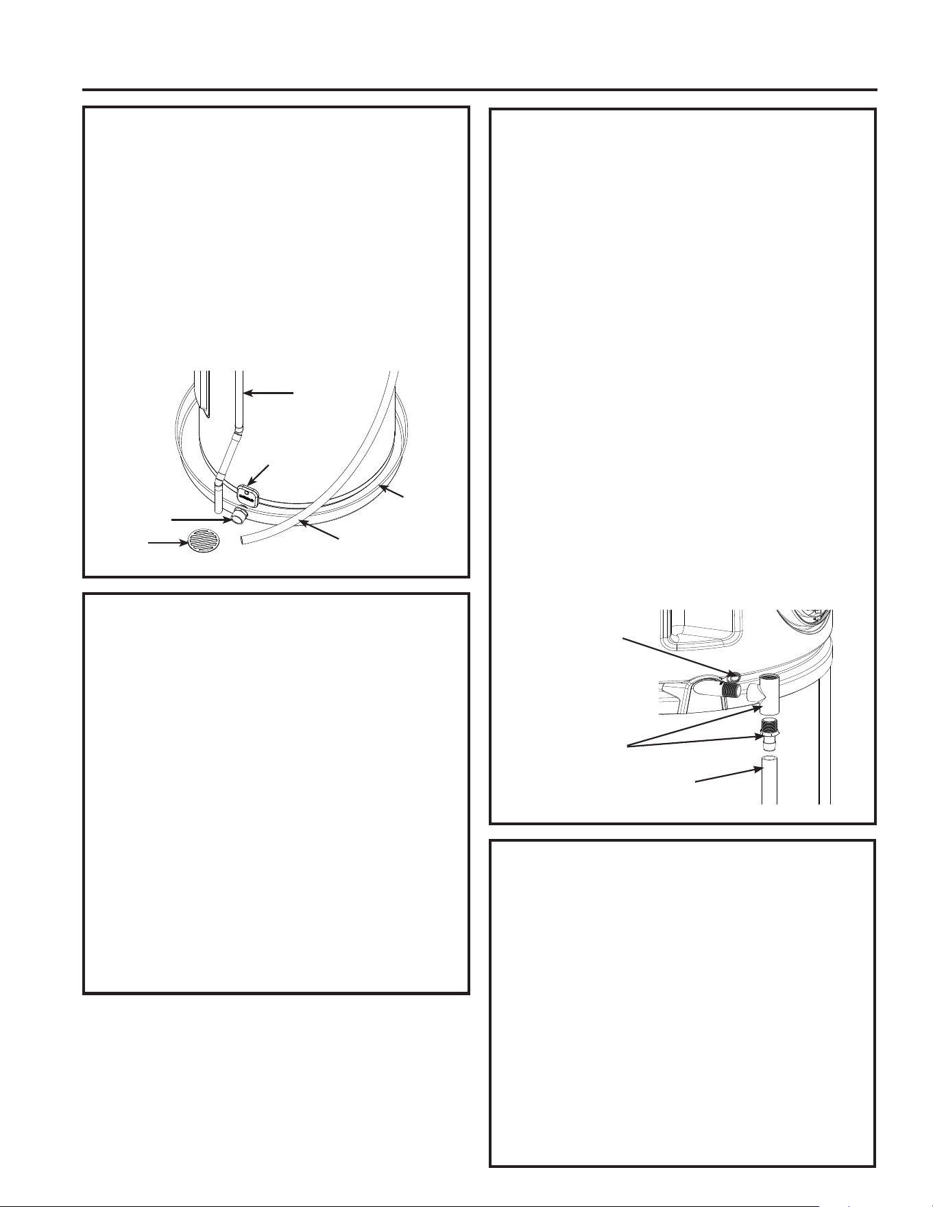
Installation Instructions
CATCH PAN INSTALLATION (If
required)
NOTE: Auxiliary catch pan MUST conform to local
codes.
Catch Pan Kits are available from the store
where the water heater was purchased, a
builder store or any water heater distributor or at
GEApplianceparts.com. The catch pan should be
2” (5.1 cm) minimum larger than the Water Heater
base diameter. To prevent corrosion and improve
Drain Valve access it is recommended that the water
heater be placed on spacers inside the catch pan.
LEAK DETECTION SENSOR &
WATER SHUT VALVE (If equipped)
Follow installation instructions supplied with sensor
(placing sensor vertically against water heater, when
using a catch pan) or flat on floor, otherwise (toward
direction water would naturally drain, such as a floor
drain). For unpainted metal catch pans, make sure
the sensor contacts do not touch the metal directly,
as this can lead to a false water leak alert.
Pair Sensor to water heater by pressing senor
button until sensor light begins blinking. Press the
Accessory button on water heater control until light
above button starts blinking. Once paired, both lights
will blink quickly and then remain solid. After a short
time, the light on the sensor will go off, to conserve
its battery.
Install Water Shut-Off Valve following instructions
packaged with valve.
CONDENSATION DRAIN
CONNECTION
This unit has a condensate drain; therefore a floor
or other drain no higher than 36” (91.4cm) above
the floor must be available in close proximity to the
water heater to allow for the shortest possible drain
line with minimal turns to be installed. Drain must
meet state and local codes. It is important to install
a
3
/4” FNPT fitting suitable for either rigid or flexible
drain line to the primary drain port coming off the
side of the unit. Diameter reductions from a
3
/4” drain
line are discouraged.
Ensure that the rigid or flexible drain line maintains a
downward slope to allow for proper gravity drainage
of condensate to the drain and to allow for proper
function of the condensate drain blockage sensor
(see page 13). If no drain is available, then a
common condensate pump with a capacity no less
than 1 gallon (3.8L)/day must be purchased and
installed. It is important to route the flexible or rigid
drain line so that the discharge water cannot contact
live electrical parts or cause water damage .
Additional parts needed:
1- Flexible 3/4” drain line and associated 3/4”-FNPT
fittings.
(Typical Installation)
THERMAL EXPANSION
If a check valve is present on the inlet water line,
it will create a “closed system.” Heating water in
a closed system creates an increase in pressure
within the water system because the pressure is not
able to dissipate in the main supply line. Referred to
as “thermal expansion”, the rapid pressure increase
can cause the relief valve to operate (releasing
water) during each heating cycle, potentially causing
premature failure to the valve or even the water
heater. The suggested method of controlling thermal
expansion is to install an expansion tank in the cold
water line between the water heater and the check
valve as shown in the following illustrations. Contact
your installing contractor, water supplier, or plumbing
inspector for additional information.
Fittings
Condensate
Drain
Overflow
Drain Line
Relief Valve
Drain
Condensate
Drain
Catch Pan (if
required)
Leak Detect
Sensor
Catch Pan
Drain
Floor
Drain
INSTALLATION INSTRUCTIONS
49-6000330 Rev. 1 25
INSTALLATION INSTRUCTIONS
WATER SUPPLY CONNECTIONS
Appliance requires water supply pressure between
20 psi to 125 psi (138 kPa to 861 kPa).
Refer to the illustration below for suggested typical
installation. The HOT and COLD water connections
are clearly marked and are ¾” NPT on all models.
When connecting to the inlet/outlet ports, the use
of ¾”female NPT tapered thread fittings with use of
thread sealant is recommended. The installation of
unions is recommended on the hot and cold water
connections so that the water heater may be
easily disconnected for servicing if necessary.
NOTE: Install a shut-off valve in the cold water
line near the water heater. This will enable
easier service or maintenance of the unit later.
IMPORTANT: Do not apply heat to the
HOT or COLD water connections. If sweat
connections are used, sweat tubing to
adapter before fitting the adapter to the
cold water connections on heater. Any heat
applied to the hot or cold water connection
will permanently damage the internal plastic
lining in these ports.
Install a vacuum relief valve and/or anti-siphon
device when required by local jurisdictions.
TYPICAL INSTALLATION
IMPORTANT: Hot water recirculation loop systems
are not recommended for use with this product.
These systems can reduce efficiency and may lead to
temperature control issues with mixing valve models.
Integrated electronic mixing valve models should not
be installed with pre-heated water from solar or other
heated sources (higher than intended user set point).
Installation Instructions
To cold water
supply
Hot water
outlet to
fixtures
Shut-off
valve
Electronic
Water
Shut-Off
Valve
Vacuum Relief or Anti-Siphon
Valve (if code required)
Union
Thermal expansion
tank
Relief Valve discharge
6” (15.2 cm) minimum
from the floor
Temperature & Pressure
Relief Valve
3/4” NPT Fitting to
Condensate Drain
Pan
Condensate
Drain Line
Conduit to Electrical Junction
Box (use only copper
conductors)
Model appearance may vary
Drain valve
Leak Detect
Sensor
26 49-6000330 Rev. 1
Installation Instructions
CAUTION
To reduce the risk of excessive
pressures and temperatures in this water heater,
install temperature and pressure protective
equipment required by local codes and no less
than a combination temperature and pressure relief
valve certified by a nationally recognized testing
laboratory that maintains periodic inspection of
production of listed equipment or materials, as
meeting the requirements for Relief Valves and
Automatic Gas Shutoff Devices for Hot Water
Supply Systems, ANSI Z21.22. This valve must be
marked with a maximum set pressure not to exceed
the marked maximum working pressure of the water
heater. Install the valve into an opening provided
and marked for this purpose in the water heater,
and orient it or provide tubing so that any discharge
from the valve exits only within 6 inches above, or
at any distance below, the structural floor, and does
not contact any live electrical part. The discharge
opening must not be blocked or reduced in size
under any circumstances.
TO FILL THE WATER HEATER
WARNING
Risk of Unit Damage - The
tank must be full of water before heater is turned
on. The water heater warranty does not cover
damage or failure resulting from operation with
an empty or partially empty tank.
Make certain the drain valve is completely closed.
Open the shut-off valve in the cold water supply line.
Open each hot water faucet slowly to allow the air to
vent from the water heater and piping.
A steady flow of water from the hot water faucet(s)
indicates a full water heater.
F75” fault code during installation: If the unit is
powered on without a full tank, the error code “F75”
will show in the display. Turn off the power, fill the
tank with water (see above), then turn the power
back on.
NOTE: The DRY TANK DETECTION feature on tank
is for the aid of installer and should NOT be used
as the primary control to prevent operation with an
empty or partially filled tank. Power should NEVER
be applied to the water heater until installer has
verified tank is filled and all air has been purged from
system.
NOTICE
For maximum heating
performance, apply 240 VAC or 208 VAC across L1
and L2 wires as shown in “Water Heater Junction
Box “ illustration.
If a 4-conductor wire is supplied to the water heater,
cap the neutral, and connect the remaining wires as
illustrated.
NOTE REGARDING UTILITY POWER-
MANAGEMENT DEVICES (Sometimes called Peak
Load Reduction Switches):
Some power-management switching devices or
even some basic timer switches exist that REDUCE
voltage from 240V to 120V during high-electricity-
demand periods. These type of device are allowable
ONLY on 120V convertible models and NOT on
240V non-convertible models.
RELIEF VALVE
WARNING
Risk of Unit Damage - The
pressure rating of the relief valve must not
exceed 150 PSI (1034 kPa), the maximum
working pressure of the water heater as marked
on the rating plate.
A new combination temperature and pressure-relief
valve, complying with the Standard for Relief Valves
and Automatic Gas Shut-Off Devices for Hot Water
Supply Systems, ANSI Z21.22, is supplied and must
remain installed in the opening provided and marked
for the purpose on the water heater. No valve of any
type should be installed between the relief valve and
the tank. Local codes shall govern the installation of
relief valves.
The BTUH rating of the relief valve must not be less
than the input rating of the water heater as indicated
on the rating label located on the front of the heater
(1 watt=3.412 BTUH).
Connect the outlet of the relief valve to a suitable
open drain so that the discharge water cannot
contact live electrical parts or persons and to
eliminate potential water damage.
Piping used should be of a type approved for
hot water distribution. The discharge line must
be no smaller than the outlet of the valve and
must pitch downward from the valve to allow
complete drainage (by gravity) of the relief valve
and discharge line. The end of the discharge line
should not be threaded or concealed and should
be protected from freezing. No valve of any type,
restriction or reducer coupling should be installed in
the discharge line.
ELECTRICAL CONNECTIONS &
GROUNDING INSTRUCTIONS
Dedicated Circuit Setup: Establish a separate
branch circuit using copper conductors. Ensure this
circuit includes an overcurrent protective device and
suitable disconnecting means. When operating at
120V, the water heater can be on a share circuit but
avoid connecting to a circuit that is already loaded
with more than half of the breaker’s amperage rating.
INSTALLATION INSTRUCTIONS
49-6000330 Rev. 1 27
INSTALLATION INSTRUCTIONS
Installation Instructions
ELECTRICAL CONNECTIONS & GROUNDING INSTRUCTIONS (Cont.)
Code Compliance: Verify that all wiring conforms to
local codes or the latest edition of the National Electrical
Code (ANSI/NFPA 70).
Junction Box Connections: The water heater is
pre-wired to the junction box at the top. Utilize the
provided opening for a 1/2” electrical fitting to complete
field wiring connections.
120VAC Models: These models are equipped with a
power cord for direct connection to a standard 120V
(60Hz) outlet.
WARNING
Ensure the power cord is plugged into
a properly grounded receptacle. Replace any damaged
power cord with one supplied by the manufacturer; do
not attempt repairs. Do not use extension cords.
Conversion Option: To enhance performance, 120V
models can be converted to a 240V or 208V power
supply. Always disconnect power before servicing.
Begin by using a Phillips-head screwdriver to remove
the junction box cover to disconnect the power cord and
internal wiring connections. Directly wire the appliance
to the 240V or 208V supply per following instructions,
ensuring all connections are secure.
240VAC Models: These models are designed to
operate solely on 240V or 208V (60Hz) and cannot be
converted to other voltages. Ensure proper connection
to a 240V or 208V power supply as specified.
Safety and Compliance Assurance: Ensure all
electrical connections meet local codes or ANSI/
NFPA 70 for grounding details and exceptions. If any
uncertainties arise, reach out to a qualified electrician.
The branch circuit wiring should include either:
1. Metallic conduit or metallic sheathed cable approved
for use as a grounding conductor and installed with
fittings approved for the purpose.
2. Nonmetallic sheathed cable, metallic conduit or
metallic sheathed cable not approved for use
as a ground conductor shall include a separate
conductor for grounding. It should be attached to
the ground terminals of the water heater and the
electrical distribution box.
To connect power to the water heater:
1. Turn the power off.
2. Remove the screw/screws holding the junction box
top cover.
3. Install L1 to L1, L2 to L2 and ground to the green
ground wire connected to the bottom of the junction
box.
4. Reinstall junction
box cover with
supplied screws,
ensuring no wies
are pinched or
exposed.
NOTE: Install
electric
connections
according to local
codes or latest
edition of National
Electrical Code
ANSI/NFPA 70.
WARNING
Proper ground connection is
essential. The presence of water in the piping
and water heater does not provide sufficient
conduction for a ground. Nonmetallic piping,
dielectric unions, flexible connectors, etc., can
cause the water heater to be electrically isolated.
Do not disconnect factory ground.
The manufacturer’s warranty does not cover any
damage or defect caused by installation, attachment
or use of any type of energy-saving or other
unapproved devices (other than those authorized by
the manufacturer) into, onto or in conjunction with the
water heater. The use of unauthorized energy-saving
devices may shorten the life of the water heater and
may endanger life and property.
The manufacturer disclaims any responsibility for
such loss or injury resulting from the use of such
unauthorized devices.
If local codes require external application of insulation
blanket kits, the manufacturer’s instructions included
with the kit must be carefully followed.
Application of any external insulation, blankets
or water pipe insulation to this water heater will
require careful attention to the following:
• Do not cover the temperature and pressure-relief
valve.
• Do not cover access panels to the heating elements.
• Do not cover the electrical junction box of the
water heater.
• Do not cover the operating or warning labels
attached to the water heater or attempt to relocate
them on the exterior of the insulation blanket.
• Do not block the air inlet/outlets in the top covers or
rear of the unit.
Junction
Box Cover
Junction
Box Cover
House
Ground
(Green)
Water Heater
Junction Box
L1
(Black)
Factory Ground
L2 (Red)
BRANCH CIRCUIT SIZING GUIDE
Max. Overload
Protection (fuse
or circuit breaker
amperage)
Min.
Circuit
Ampacity
(MCA)
“Copper Wire Size
AWG Based on
N.E.C. Table 310-16
(167°F/75°C)”
15 0-15 14 AWG
20 15.1-20 12 AWG
25 20.1-25 10 AWG
30 25.1-30 10 AWG
28 49-6000330 Rev. 1
INSTALLATION CHECKLIST
1. Tank location:
– Does room size require louvered door, ducting kit, or similar ventilation? 10’ x 10’ x 7’ (700 cu.ft./19.8
cu.m.) or 240 square inches (0.15 m
2
) open air-flow area needed.
– Back of unit away from wall by 7 inches (17.5 cm), and sides have at least 7 inches (17.5 cm)
clearance. (6 inches (15.2 cm) clearance for earthquake strap installations, with additional clearance on
the opposite side of the unit.)
– Front of unit is free and clear.
– Is the water heater level? If no, add shims under the base of the unit to ensure proper function of
sensors.
2. Verify Air Filters are installed. (Installed on product.)
3. Plumbing connections:
– Does not prevent air filter removal.
– No leaks after filling the tank with water, either when water is flowing or not.
– Install shut-off valve and leak detect sensor.
4. Condensate lines are in place:
– Main flexible or rigid drain line installed and directed to a drain or condensate pump. Reducer fittings are
not recommended.
5. Temperature and pressure-relief valve is working and drain line completed per local code.
6. Electrical verify 208/240 VAC to L1 and L2 at tank or plugged into a standard, 120VAC outlet on 120V
models.
7. Electrical connection does not prevent air filter removal.
8. Verify control panel displays 120°F (49°C) Hybrid mode. Assist user in how to adjust temperature and
modes (see “Water Temperature Adjustment” section on page 4).
9. Download SmartHQ™ App and connect appliance and accessories to WiFi/Bluetooth
®
.
Installation Instructions
WHAT TO EXPECT FOR “NORMAL STARTUP” IN HYBRID MODE
After the unit has been installed, with all electrical and water connections secure and checked, then the unit
should be filled with water (vent tank by opening a hot water faucet somewhere in home to allow tank to fully fill
with water). Once tank is full and power is energized, you may experience the following:
Elapsed Time HEWH Actions Comments
0 to 3 minutes Unit will go through self-check. Fan
will turn on after 1 minute.
This 3-minute off-time prevents compressor
damage. A clicking noise may be heard during
startup.
3 to 12 minutes Compressor turns on. Fan continues
to run.
This 9-minute period is used to ensure the tank
is full of water (Dry-fire prevention algorithm). If
no water is detected, a F75 Fault code will be
displayed.
12 minutes and
beyond
Compressor turns off (Fan will run
for 30 minutes after any compressor
operation). Normal heating operation
resumes.
The water heater is operating in Hybrid mode.
Quickly provides initial amount of hot water with
heating elements, then switches to efficient heat
pump for majority of heating.
NOTE: The heat pump operating range is 35°F to 120°F (2°C to 49°C). If the ambient temperature is outside
of this range, the heat pump will turn off and the electric elements will be used until the ambient temperature
returns to within the operating range.
INSTALLATION INSTRUCTIONS

49-6000330 Rev. 1 29
Frequently Asked Questions
Filter:
Q: Why are there Air Filters?
A: In Hybrid and Heat Pump the unit moves air through
the system. Air Filters protects the unit from dirt.
Clean Air Filters improves efficiency.
Q: How to clean the Air Filters?
A: Leave power on and remove Air Filters. Air Filters can
be vacuumed clean or rinsed with warm water. Once
cleaned, reset the alarm by pressing and holding the
Filter button. A dirty filter will reduce water heater
efficiency!
Modes:
Q: What is Heat Pump?
A: Heat Pump is the most-efficient mode. It takes
heat from the air to heat water, thereby cooling the
surrounding air. Slower recovery but most-efficient
mode.
Q: What is Hybrid?
A: The Hybrid mode combines benefits of Heat Pump
with the speed and power of Standard Electric. This
provides great performance with less energy.
Q: What is High Demand?
A: High Demand can be used when hot water usage is
higher than normal. The unit will be less efficient but
will heat water faster in response to long water draws.
For all normal draws, the unit will still use the efficient
Heat Pump the majority of the time.
Q: What is Vacation mode?
A: If you are gone for an extended period, this mode
lowers the water temperature to reduce energy used.
Unit will switch to the previous mode one day before
you get back.
Q: What is Standard Electric?
A: Standard Electric mode uses only the resistance
heaters to heat the water. This gives faster hot water
recovery than Hybrid mode, but uses more energy.
This mode operates without the fan, stopping the cool
air normally discharged during heat pump operation.
Operation:
Q: Why can I hear the unit run?
A: In the most energy-efficient modes, Heat Pump,
Hybrid, and High Demand, the method used to heat
the water uses a fan that can be heard while running.
Q: The heat pump is not running its normal length of
time. What causes this?
A: Under some conditions, the GeoSpring™ Hybrid
Water Heater will operate using the electric elements
instead of the heat pump to protect your unit and
ensure hot water is available to you. These conditions
include extreme cold ambient temperature (<35°F),
extreme hot ambient temperatures (>120°F), or very
low voltage conditions. The unit will return to normal
operation when conditions permit.
Q: Why is one of the operating mode LEDs flashing?
A: In Hybrid Mode and High Demand Mode, the
Standard Electric Mode LED will flash anytime the
heating elements are active, such as during the initial
recovery from a large draw. In Standard Electric
Mode, the operating mode LED will flash after 48
hours as an indication that the unit is not operating
in the most energy efficient mode. These are both
normal conditions and do not indicate an operating
issue.
Q: Why isn’t the temperature setting always displayed on
the control?
A: The display screen will go blank after a period of
inactivity in order to conserve energy. Pressing
any button will wake the control and display the
temperature setpoint.
Anode Rod:
Q: What does an anode rod do?
A: The anode rod provides protection against corrosion
of the water heater tank. The anode rod must be
replaced before it is consumed and no longer offering
protection against corrosion.
Q: How to change the anode rod?
A: Refer to page 15. Models equipped with an anode
depletion sensing feature require a unique anode that
can be ordered through GE Appliances Service.
Q: What can I do about a sulphur smell coming only from
my hot water?
A: Some areas have water conditions that may cause an
odor to develop in the water heater. Aluminum-Zinc
alloy replacement rods are available to address the
condition. See page 14 for details.
FREQUENTLY ASKED QUESTIONS
30 49-6000330 Rev. 1
Troubleshooting
Before you call for service.
Save time and money! Review the chart below first and you may not need to call for service.
CAUTION
For your safety, DO NOT attempt repair of electrical wiring, controls, heating elements or other
safety devices. Refer repairs to qualified service personnel.
Problem Possible Causes What To do
OPERATION AND PERFORMANCE
Not enough or no hot water Water temperature may be set
too low
• See the Water Temperature Adjustment section (see page 4). If the product
has an integrated mixing valve, turn capacity setting up to “High” or
“X-High” to increase available hot water capacity.
Hot water usage pattern exceeds
the capability of the water heater
in current mode
• Change to different mode.
• Wait for the water heater to recover after an abnormal demand.
Cold water inlet temperature
may be colder during the winter
months
• This is normal. The colder inlet water takes longer to heat.
• Consider increasing the set temperature as described in the Water
Temperature Adjustment section or increase capacity setting on models
equipped with an electronic mixing valve.
Leaking or open hot water
faucets
• Make sure all faucets are closed.
Long runs of exposed pipe, or
hot water piping on outside wall
• Insulate piping.
Not enough clearance to allow
air to circulate for the heat pump
• Make sure unit is 7” away from the wall and has 8” clearance above the air
filter.
Room is too small or too cool,
slowing heating performance
• Smaller rooms can lead to cooler room temperatures due to the heat pump
cooling the air. If the room is smaller than 700cu.ft. (10’x10’x7’), install
louvred doors or similar ventilation.
• Cooler room temperatures can cause the water heater to take longer to fully
recover to the set temperature. Consider increasing the set temperature as
described in the Water Temperature Adjustment section.
A fuse is blown, circuit breaker
tripped, or electric service to
your home may be interrupted
• Replace fuse or reset circuit breaker.
• Contact the local electric utility.
Inadequate wiring • See the Installation Instructions.
Manual reset high limit (ECO) • See the Safety Controls section, see page 5.
Water Connections to unit
reversed
• Correct piping connections.
Dip tube damaged • Contact your local installer, plumbing contractor, or previously agreed upon
service agency.
Recirculating System
Interference (if installed)
• Hot water recirculation systems should not be installed on mixing valve
models
Water is too hot Water temperature is set too
high
• See the Water Temperature Adjustment section.
Electronic Control has failed • Call for service.
Water heater is making the
room cooler
Room is not vented properly or
is too small
• If the room is smaller than 700cu.ft. (10’x10’x7’) then it must have a louvred
door or other means to allow air exchange with surrounding rooms.
Heat is removed from the air to
heat the water
• This is normal.
CONTROL PANEL
The heater is beeping and
the display says F75
The water heater has not been
filled with water before powering
up. Powering up the heater
without water will damage the
electric heaters. The water
heater warranty does not cover
damage or failure resulting
from operation with an empty or
partially empty tank.
• Fill the tank completely with water. Press ENTER to stop the alarm and
then cycle power when the tank has been filled.
• If the unit has been confirmed to be filled with water, and an F75 code is
experienced, it is possible that the code may be a false indicator due to
certain unique environment conditions encountered during the start up. If
the unit is full of water, turn the breaker off for about 10 minutes to allow
the water temperature to stabilize, then turn the breaker back on. If the F75
code persists, schedule GE Appliances Service.
The heater is beeping, the
anode light is on (on some
models), and the display
says F70
The anode rod is approaching
end of life and it is
recommended to replace it
in order to continue to offer
protection from corrosion.
• Call for service or follow the instructions on how to replace the anode
rod on page 15. Ensure that the anode depletion sensing anode rod or
other GE Appliances approved anode rod is installed. Installation of an
unapproved anode rod will VOID the warranty.
TROUBLESHOOTING

49-6000330 Rev. 1 31
TROUBLESHOOTING
Troubleshooting
Problem Possible Causes What To do
CONTROL PANEL (Cont.)
The heater is beeping and
the display says F41
The anode rod is not connected
properly and the water heater
may not be protected from
corrosion.
• Check that the tank is filled completely with water.
• If the tank is full of water and the F41 code persists, contact GE Appliances
service.
• Press anode button to silence alarm.
The mode indicator light is
flashing
Normal operation • In Heat Pump (Turtle), Hybrid or High Demand (Rabbit) Mode, the
corresponding LED light will flash whenever the Electric Resistive Elements
are active.
• These conditions are normal and do not indicate an operating issue.
The filter light or F74 is on The filter requires cleaning.
A clean filter is necessary for
effective operation.
• Follow the instructions on how to remove and clean the filter on page 13.
• Repeated dirty filter alarms that do not resolve by cleaning the filter may be
an indication of a sealed system failure. Contact service.
The heater is beeping and
the screen flashes, F76.
Unit is not receiving the correct
rating plate voltage
• Turn off power to water heater (generally at the breaker panel). Then read
Electrical Connections section of the installation Instructions, see page 26,
then contact the installer to verify electrical input to the water heater.
The heater is beeping and
the screen displays an
error code
Heat pump system or control
issues
• The water heater may automatically switch to another available heating
mode to ensure continued availability of hot water. Contact service
immediately and give them the codes listed on the display screen.
• To quiet the beeping, press either the + or - button.
OTHER
Water heater makes
sounds
A fan is used to move air
through the system
• Some amount of fan sound is normal. If you hear an abnormal sound or
the sound level seems unusually loud (ex, louder than a window A/C), then
contact service.
The EEV valve makes clicking
noises upon power up
• This is normal.
Unit is not making normal
sounds
If unit is using electric
resistance elements, it will
not make fan or compressor
sounds.
• Check mode of unit.
Rumbling noise Water conditions in your home
caused a buildup of scale or
mineral deposits on the heating
elements
• Remove and clean the heating elements. This should only be done by a
qualified service person or plumbing contractor.
Squealing/Chirping sound
when drawing hot water
In certain usage conditions,
noise may transmit through
plumbing from the integrated
mixing valve
• Increasing user set point or lowering capacity setting may address
this condition on integrated mixing valve models. Consult a plumbing
professional to install a pressure limiting device, if due to high water
pressure.
Intermittent EMV motor
noise on integrated mixing
valve models
A soft motot noise may be heard
during normal operation due to
movement of control valve.
• This noise is normal and does not indicate any issue with product.
Water dripping down the
outside of the heater
Hot/Cold water connections or
other parts have loosened
• Tighten the loose connections. This should only be done by a qualified
service person or plumbing contractor.
Relief valve producing
popping sound or draining
Pressure buildup caused by
thermal expansion to a closed
system
• This is an unacceptable condition and must be corrected. See Thermal
Expansion section on page 23. Do not plug the relief valve outlet. Contact
a plumbing contractor to correct this.
Hot water has a rotten egg
or sulfur smell
Certain water supplies with high
sulfate content will react with
the anode rod that is present in
all water heaters for corrosion
protection of the tank
• The odor can be reduced or eliminated in most water heaters by replacing
the anode rod with less-active material rod. In some cases, an added
step of chlorinating the water heater and all hot water lines may be
necessary. Contact your local water professional or plumber for options
and instructions.
Go to GEAppliances.com/waterheater for information on purchasing
this replacement anode rod. A qualified servicer or plumber should do
this replacement. Use of a non-GE Appliances approved anode rod, or
operating the water heater without a GE Appliances approved anode rod
will VOID the warranty.
• In certain cases, increasing the tank temperature to 140°F (60°C) can
reduce this odor issue. Reference the Water Temperature Adjustment
section of the Important Safety Information of this manual for procedure
and dangers of scalding water. Installation of temperature limiting valves
can be used to reduce risk of scalding.
32 49-6000330 Rev. 1
Fault Codes
Fault Code
Displayed
Condition Action
F10, F20 Lower Heating Element Failure Call Service to replace respective heating element
F11, F21 Upper Heating Element Failure
F14 Compressor Failure or Discharge temp. too high Call service
F15 Fan Failure Call service
F16*, F17 No Hot Water - Mixing Valve Outlet DC TCO Tripped on EMV
models or missing jumper wire on non-EMV models
Call Service
F18*, F63* Mixing Valve Failure Call service
F19 Runaway Heat Source Call Service
F30 Tank Temperature (T1) Failure open/short Call Service to replace sensor
F31 Tank Temperature (T2) Failure open/short Call Service to replace sensor
F32 Tank Temperature, (T1 or T2) Failure Call Service to replace required sensor
F34 T3a Sensor (Evap inlet temperature) Failure Call service
F35 T3b Sensor (Evap outlet temperature) Failure Call service
F36 T4 Sensor (Compressor outlet) Failure Call service
F37 T5 Sensor (ambient temperature) Failure Call service
F38* Mixing Valve Outlet Temperature (T6) Failure Call Service to replace required sensor
F39* Mixing Valve Cold Inlet Temperature (T7) Failure Call Service to replace required sensor
F41# Sensing Anode miswired or Empty Tank or Anode Rod Wired
Incorrectly
Confirm wire is connected to sensing anode terminal. Call
Service otherwise.
F43 Water leak detected (from Leak Detect Module) Inspect for water leak and repair, as required
F42 Condensate Sensor Failure Call Service to replace required sensor
F46, F53 Evaporator Not Frost Free. Probable refrigerant leak or
Evaporator Not Defrosting
Call service
F47 Seal System Vapor Lock Fault Call service
F48 T5 Ambient Temperature Check Technician service data - Ambient beyond Heat Pump
operating conditions
F49 Control Board - high temperature fault Call service
F50 Inverter Fault Call service
F51 Inverter Software Fault Call service
F52 Compressor Discharge Temperature Low Call service
F54 Superheat too low. Possible refrigerant leak. Call service
F55 Electronic Expansion Valve Out of Range. Probable refrigerant
leak.
Call service
F56 Electronic Expansion Valve Out of Range. Probable refrigerant
leak; or Refrigerant Leak Test. Probable refrigerant leak.
Call service
F57 Concurrent Load High Current Call service
F60 AC detection Failure Call Service to confirm wiring is correct
F61 Tank water temperature is too hot Should self correct
F62 Incoming water too hot Reduce any preheat of inlet water or call for Service
F70# Anode Depleted Call Service to replace sensing anode (see anode
replacement section in manual).
F73 Condensate Drain Pan Port Clogged Clean condensate drain obstruction. See page 13
F74 Filter is dirty. If fault repeats after clearing, probable refrigerant
leak.
Clean Filter. See page 13
F75 Dry Tank Fault Confirm water in tank. See page 25.
F76 Voltage too low at power up. Call Service for probable miswire. See page 26.
F77 Stuck Key Failure Call Service to diagnose and repair
F78 Leak Sensor detected water Determine source of water leak and correct. Reset shut-off
valve, if equipped (see page 13). Call plumber to resolve,
otherwise.
F81 Leak Sensor Battery is low Replace Leak Sensor Battery
F90 E2 module unplugged or damaged Call Service to diagnose and repair
F91 or F92 DataFlash Fault Cycle Power to correct fault after service
F93 No Personality detected in control board Call Service
F94 WiFi Board Failure (WiFi icon dark) Call Service to diagnose and repair
F95 CTA Communication module software fault Call Service
F96 CTA module disconnected or low battery Reconnect CTA module or replace battery
* Applies to models with integrated mixing valve
# Applies to models with sensing anode
TROUBLESHOOTING
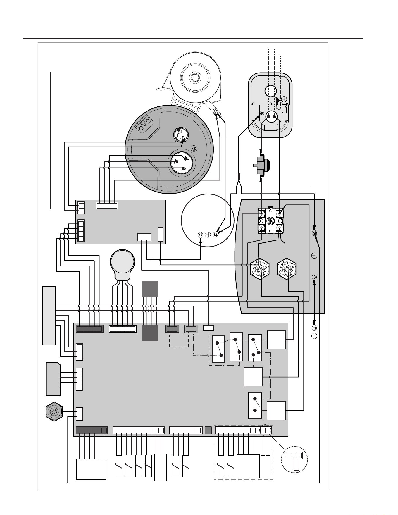
49-6000330 Rev. 1 33
Wiring Diagram
1
1
2
MAIN BOARD
J807
4 3 2
1
2
3
4
5
J804
J801
J802
1
2
3
4
5
6
K403-COMPRESSOR RELAY
COM
NO
V
U
W
J806
3 2 1
1
2
3
4
5
6
7
J602
ANODE
WIFI
MODULE
6
7
8
9
10
T3a
T3b
T4
T5
CONDENSATE
OVERFLOW
K402-LE RELAY
COM
NO
K401-UE RELAY
NC
8
9
10
11
J808
RED
e2 Personality
module
T1
T2
T7
T6
ELECTRONIC
MIXING
VALVE
[EMV]
EMV DC TCO1
EMV DC TCO2
COM
NO
K404-FAN RELAY
COM
TAB
NO
J405-YELLOW
5
4
3
2
1
J803
EEV
RJ45
J601
1
2
3
4
5
COMPRESSOR
240V/120V HPWH WIRING DIAGRAM
VARIABLE SPEED
8
9
10
11
(if equipped)
Non-EMV models
(use J802 Jumper Cable)
BLACK
VARIABLE SPEED FAN
INVERTER GEA3
J805-BLACK
M402
UE LUG-L1
OUT
M403
LUG-L1
IN
M401
LE LUG-L1
OUT
J401
RJ45
INVERTER
BOARD
TOP COVER
INVERTER
POWER
COMPRESSOR
U WV
SWITCHED-L1
SWITCHED-L1
1
2
J404-RED
J602
TAB-L2
1 2
DC TCO
J607
G
1
2
J608
WRAPPER
STUD B
STUD A
J606
TANK
1
2
41 2 3
J603
4
3
2
1
J809
BLACK
SHUTOFF
VALVE
1
2
3
4
5
6
Note:120V model receives factory installed Power Cord
JUNCTION BOX
COVER
Arc TCO: 90C
(On Main Board Rear Enclosure)
TANK MUST BE ELECTRICALLY GROUNDED
NOTE: Any wiring replaced in field must be replaced with 105°C
minimum rated wire of equal or heavier gauge.
1
3
4
2
TCO: 180F
[Located on Tank]
UPPER ELEMENT
LOWER ELEMENT
BLACK
BLACK
BLACK
BLACK
BLACK
BLACK
BLACK
BLACK
BLACK
BLACK
BLACK
BLACK
BLACK
BLACK
BLACK
BLACK
BLACK
BLACK
BLACK
L1/Line
L2/Neutral
Ground
BLACK
BLACK
WHITE
WHITE
WHITE
WHITE
WHITE
WHITE
YELLOW
YELLOW
YELLOW
YELLOW
YELLOW
YELLOW
NAVY
NAVY
NAVY
NAVY
NAVY
AQUA
AQUA
AQUA
PURPLE
PURPLE [Funconal Ground]
PURPLE
BROWN
BROWN
GREEN
GREEN
GREEN
GREEN
GREEN
GREEN
Splice
GREENGREEN [Funconal Ground]
GREEN GREEN
RED
RED
RED
RED
RED
RED
RED
RED
RED
RED
RED
RED
RED
RED
RED
RED
RED
RED
GRAY
GRAY
GRAY
ORANGE
ORANGE
ORANGE
ORANGE
ORANGE
WIRING DIAGRAM

34 49-6000330 Rev. 1
Notes
49-6000330 Rev. 1 35
Staple your receipt here. Proof of the original purchase
date is needed to obtain service under the warranty.
LIMITED WARRANTY
GE Appliances Limited Warranty
What Is Not Covered:
■ Servicetripstoyourhometoteachyouhowtouse
the product.
■ Improperinstallation,deliveryormaintenance.
■ Replacementpartsshippingandhandlingandcostto
remove defective part or tank after the first year limited
warranty are NOT covered.
■ Failureoftheproductifitisabused,misused,altered,or
used for other than the intended purpose.
■ Useofthisproductwherewaterismicrobiologicallyunsafe
or of unknown quality, without adequate disinfection before
or after the system.
■ Replacementofhousefusesorresettingofcircuitbreakers.
■ Damagetotheproductcausedbyaccident,lightning,fire,
flood or acts of God.
■ Incidentalorconsequentialdamagecausedbypossible
defects with this appliance, its installation or repair.
■ Productnotaccessibletoproviderequiredservicein a safe
manner. Attic installation must have flooring and accessible
stairs.
■ Ifproductremovedfromoriginalinstallationlocation.
■ Ifproductorotherappliancemustbemovedfor
service access.
■ Damage,malfunctionorfailurecausedbytheuseofrepair
service not approved by GE Appliances.
■ Damage,malfunctionorfailurecausedbytheuseof
unapproved parts or components.
■ Damage,malfunctionorfailurecausedbyoperatingthe
water heater with the anode rod removed.
■ AnodeRodinspectionandreplacementoroperatingthe
water heater without an anode rod. Changing from the
original anode rod to an alternate material to address water
quality issues.
■ Damage,malfunctionorfailureresultingfromoperatingthe
water heater with an empty or partially empty tank.
■ Damage,malfunctionorfailurecausedbysubjectingthe
tank to pressure greater than those shown on the rating
label.
■ Damage,malfunctionorfailurecausedbyoperatingthe
water heater with electrical voltage outside the voltage
range listed on the rating label.
■ Waterheaterfailureduetothewaterheaterbeingoperated
in a corrosive atmosphere or any water quality condition
that affects the proper functioning or appearance of the
water heater.
■ Ifthiswaterheaterisusedforotherthanresidentialprivate
family use, labor will not be covered under warranty, and
the parts warranty is reduced to 1 year from the date of
purchase.
■ Accessorypartsnotcoveredbeyond1yearfromdateof
purchase.
EXCLUSION OF IMPLIED WARRANTIES—Your sole and exclusive remedy is product repair as provided in this
Limited Warranty. Any implied warranties, including the implied warranties of merchantability or fitness for a
particular purpose, are limited to one year or the shortest period allowed by law.
This limited warranty is extended to the original purchaser and any succeeding owner for products purchased for home use within
the USA. If the product is located in an area where service by a GE Appliances Authorized Servicer is not available, you may
be responsible for a trip charge or you may be required to bring the product to an Authorized GE Appliances Service location for
service. In Alaska, the limited warranty excludes the cost of shipping or service calls to your home.
Some states do not allow the exclusion or limitation of incidental or consequential damages. This limited warranty gives you
specific legal rights, and you may also have other rights which vary from state to state. To know what your legal rights are, consult
your local or state consumer affairs office or your state’s Attorney General.
For product purchased outside of the US, contact your dealer for Warranty and Service information.
Warrantor for Products Purchased in the United States:
GE Appliances, a Haier company
Louisville, KY 40225
All warranty service is provided by our Factory Service Centers, or an authorized Customer Care® technician. To schedule service
for your GE water heater call GE Water Heaters at 1-800-943-8186. Please have your serial number and your model number
available when calling for service. Servicing your appliance may require the use of the onboard data port for diagnostics. This gives
a GE Appliances factory service technician the ability to quickly diagnose any issues with your appliance and helps GE Appliances
improve its products by providing GE Appliances with information on your appliance. If you do not want your appliance data to be
sent to GE Appliances, please advise your technician not to submit the data to GE Appliances at the time of service
For The Period Of: We Will Replace:
One Year
From the date of the
original purchase
Any factory specified part of the water heater which fails due to a defect in materials or workmanship.
During this limited one-year warranty, we will also provide, free of charge, all labor and related service to
replace the defective part. Replaced water heater or parts will be warranted for the remaining period of the
original product warranty.
Second through Tenth
Year
From the date of the
original purchase
Any part of the Water Heater which fails due to a defect in mater ials or workmanship. During this limited
second through the end of the warranty period, labor and related service to replace the defective part
are not included. Replaced water heater or parts will be warranted for the remaining period of the original
product warranty. Accessories, such as leak detect sensor, supplied with this product will be warranted for
1 year from the date of purchase.
*Warranty is based on the 6th and 7th digit of model number located on rating plate (e.g.: PF40S10FP* has a part
warranty of 10 years).
36 49-6000330 Rev. 1
Printed in China
Consumer Support
CONSUMER SUPPORT
Register Your Appliance
Register your new appliance on-line at your convenience! Timely product registration will allow for enhanced
communication and prompt service under the terms of your warranty, should the need arise.
• Scan QR Code on product registration card, or on product.
NOTE: This is just an example of what a QR code represents.
• Or go to GEAppliances.com/register
• Or mail in your pre-printed registration card included in the packing material
Consumer Service
If you have a question or need assistance with your new water heater on adjustments, repairs, or routine
maintenance:
• Review the Troubleshooting Tips or Care and Cleaning sections of this Owner’s Manual.
• Contact your local installer, plumbing contractor, or call GE Appliances Service and Support at 1-800-943-8186.
NOTE: Your installer phone number may be located on the product label.
If you still have issues, contact the GEA Customer Support at GEAppliances.com/waterheater
Parts and Accessories
Individuals qualified to service their own appliances can have parts or accessories sent directly to their homes.
(VISA, MasterCard and Discover cards are accepted). Order on-line today 24 hours every day.
In the US, go to GEApplianceparts.com
Contact Us
If you are ultimately not satisfied with the service you receive, contact us on our Website with all the details including
your phone number, or write to:
In the US: General Manager, Customer Relations |GE Appliances, Appliance Park |Louisville, KY 40225
GEAppliances.com/contact