

Contents
1. Package Contents .......................................................................................................................... 1
2. Technical parameters ................................................................................................................... 1
3. Interfaces ....................................................................................................................................... 3
3.1. Transmitter unit ..................................................................................................................... 3
3.2. Receiver Unit .......................................................................................................................... 4
3.3. LEDs & Button (Receiver unit)............................................................................................. 6
3.4. LEDs & Button (Transmitter unit) ....................................................................................... 6
1
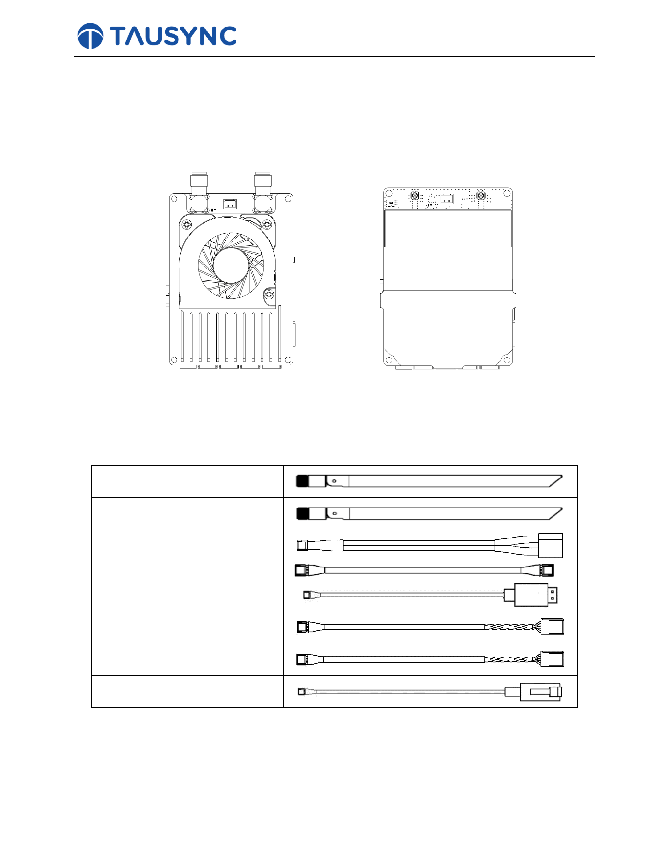
1. Package Contents
Receiver Unit Transmitter Unit
Accessories
Receiver antenna x 2
Transmitter antenna x 2
Power cable x2
Serial cable (Receiver Unit) x 2
Serial cable (Transmitter Unit) x
2
RC cable (Receiver Unit) x 2
RC cable (Transmitter Unit) x 2
RJ45 cable x 2
2. Technical parameters

2
Parameters
Value
Frequency
2.4GHz & 5GHz
Band width
10MHz
Power
Modulation
OFDM
Constellation
BPSK, QPSK, 16QAM
FEC
LDPC (1/2, 2/3, 3/4, 5/6)
Duplex
TDD
Downlink throughput
2Mbps ~ 10Mbps
Uplink throughput
600kbps
Encryption
AES 256 (Optional)
Interface
Power*1, Ethernet*1, TTL*2, S.BUS*2, PPM*1
Weight
19g
Dimension
63.24*46.83*10.43mm
Rated voltage
DC 12V ~ 26V
Working temperature
-40°C ~60°C
3
3. Interfaces
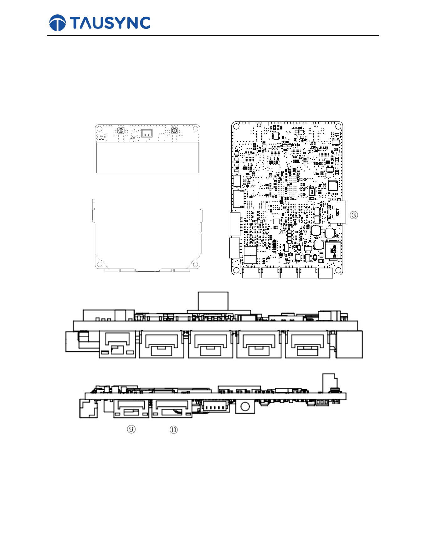
3.1. Transmitter unit
① ②
④ ⑤ ⑥ ⑦ ⑧
① RF port:
An IPEX RF port connects to an antenna through RF cable.
② RF port:
An IPEX RF port connects to an antenna through RF cable.
③ Type-C USB port.
4
Use for Debugging
④ Control Bus0 port:
Connects to Control Bus receiver. Pinouts of the Control Bus port are GND from left to right.
⑤ Control Bus1 port:
Connects to Control Bus receiver. Pinouts of the Control Bus port are GND→ 5V from left to right.
⑥ Control Bus 2 port:
connects to Control Bus receiver. Pinouts of the Control Bus port are GND→ 5V from left to right.
⑦ Serial port 1:
Serial port for telemetry, ttl(voltage level 3.3V) or RS232. Pinouts of the serial port is Tx Rx GND
seen from left to right in above figure.
⑧ Serial port 2:
Serial port for telemetry, ttl(voltage level 3.3V) or RS232. Pinouts of the serial port is Tx Rx GND
seen from left to right in above figure.
⑨ Power Port:
Power iinput (DC12V ~ 26V). Pinouts of the power port are PWR GND from left to right.
⑩ Ethernet Port:
Video input from a camera and web-page management interface. Pinouts of the Ethernet port is R- R+
G T- T+ from left to right.
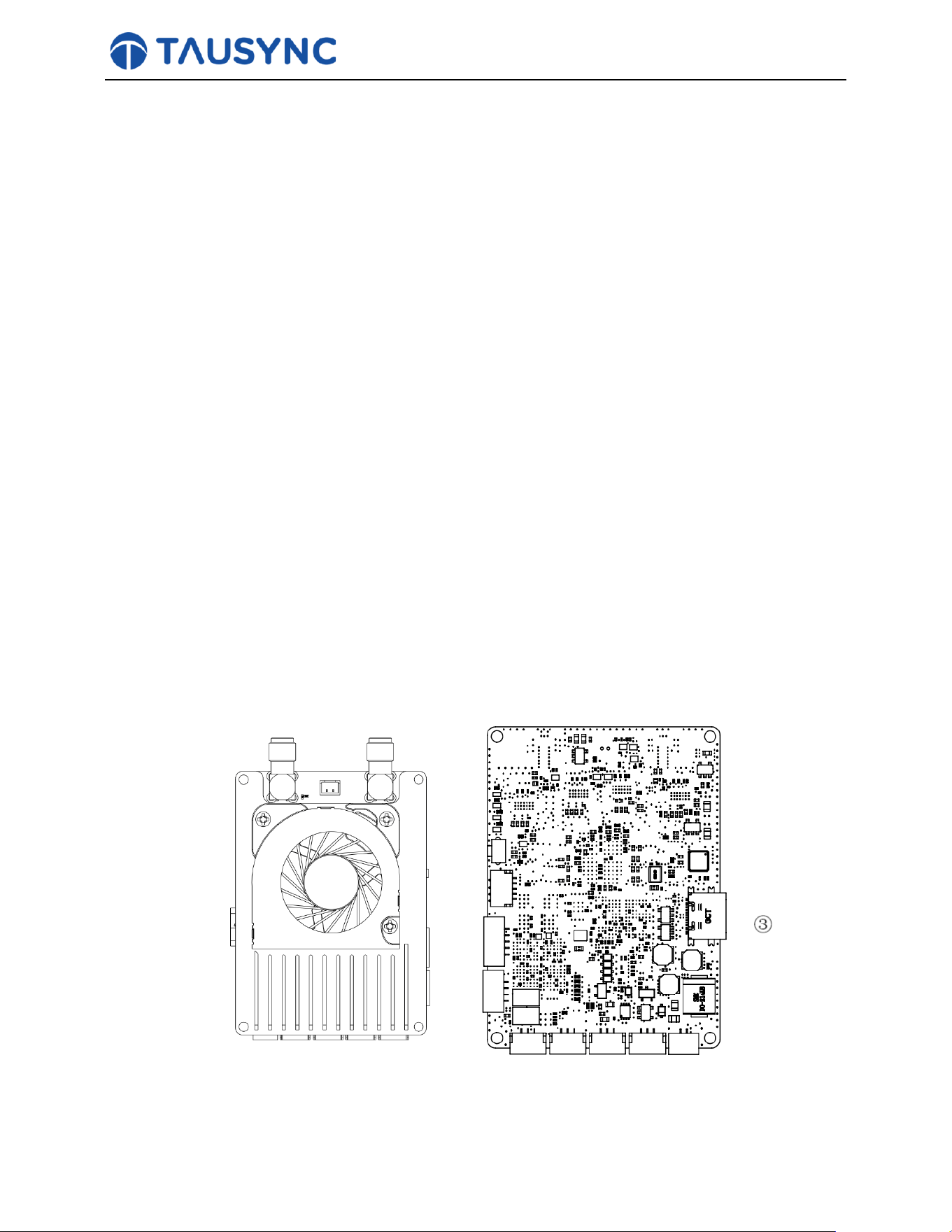
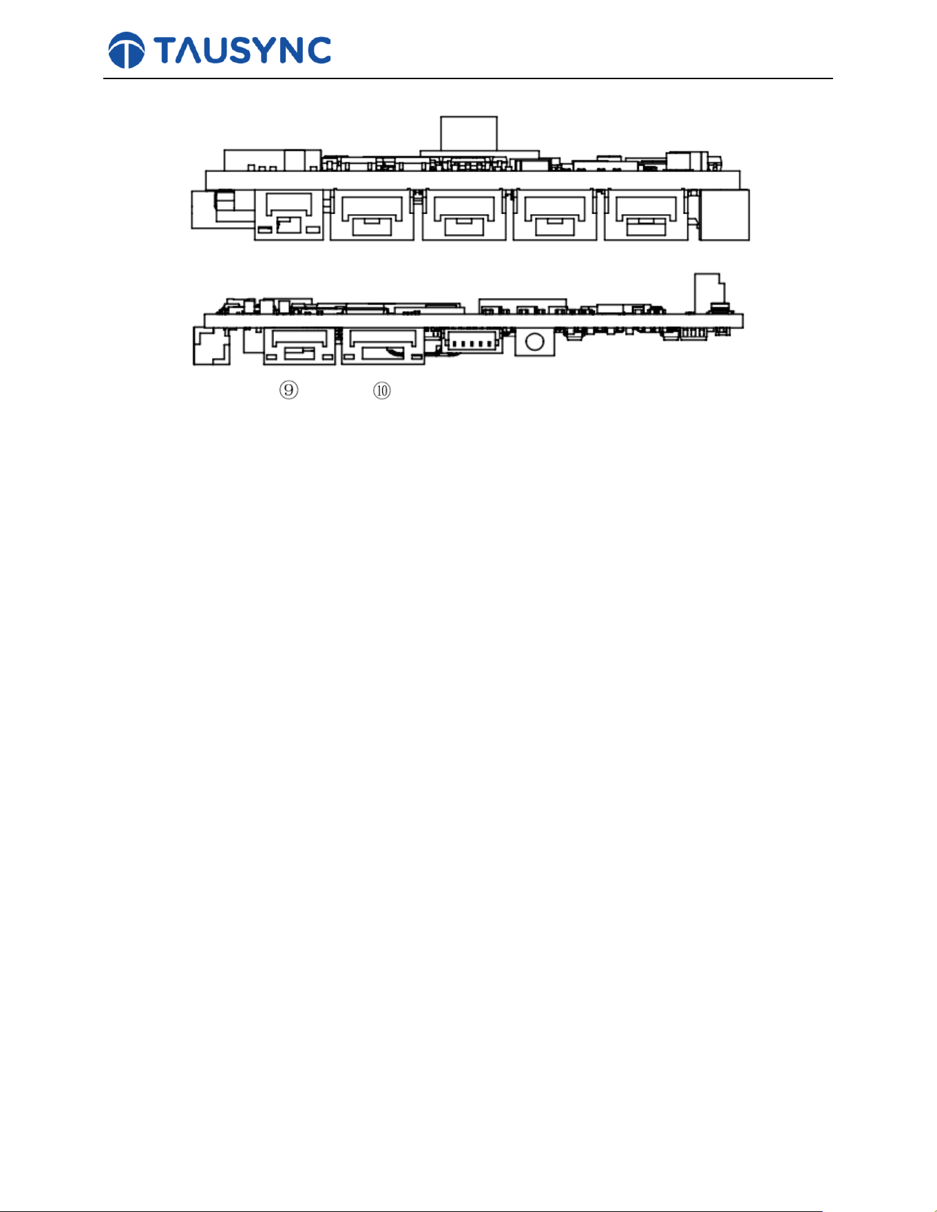
3.2. Receiver Unit
① ②
5
④ ⑤ ⑥ ⑦ ⑧
① RF port:
An IPEX RF port connects to an antenna through RF cable.
② RF port:
An IPEX RF port connects to an antenna through RF cable.
③ Type-C USB port.
Use for Debugging
④ Control Bus0 port:
Connects to a controller. Pinouts of the Control Bus port are GND from left to right.
⑤ Control Bus1 port:
Connects to the receiver. Pinouts of the Control Bus port are GND→ 5V from left to right.
⑥ Control Bus2 port:
connects to the receiver. Pinouts of the Control Bus port are GND→ 5V from left to right.
⑦ Serial port 1:
Serial 1
st
telemetry port connects to PC USB port through TTL to USB, ttl (voltage level 3.3V). Pinouts
of the serial port is GND Rx Tx from left to right
⑧ Serial port 2:
Serial 2
nd
telemetry port connects to PC USB port through TTL to USB, ttl (voltage level 3.3V).
Pinouts of the serial port is GND Rx Tx from left to right
⑨ Power Port:
Power input (DC12V ~ 26V). Pinouts of the power port are PWR GND from left to right.
⑩ Ethernet Port:
Video input from a camera and web-page management interface. Pinouts of the Ethernet port is R- R+
G T- T+ from left to right.
6
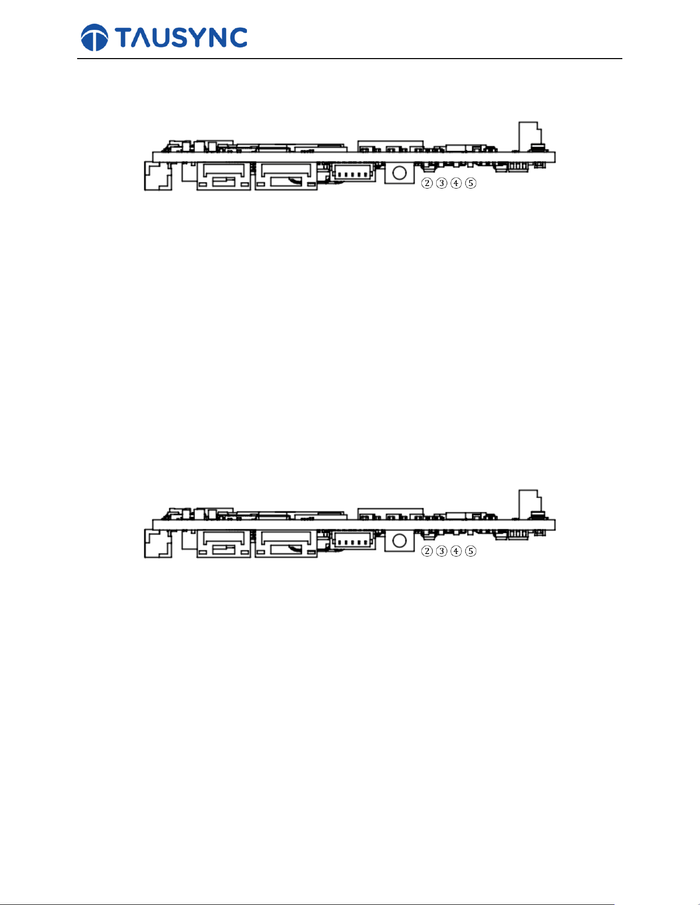
3.3. LEDs & Button (Receiver unit)
①
① Bind button:
Press and hold until LED1&LED2 start flashing, it’s bound already before factory delivery.
② LED1:
It’s off when the radio link is connected.
③ LED2:
It’s off when the radio link is connected.
④ LED3:
Solid on in orange, 100Mbps Ethernet physical link connected.
⑤ LED4:
Flickering in green, when there’s data transmission.
3.4. LEDs & Button (Transmitter unit)
①
① Bind button:
Press and hold until LED1&LED2 start flashing, it’s bound already before factory delivery.
② LED1:
Solid on in green: Receiver-to-Transmitter link connected.
③ LED2:
Solid on in orange: Transmitter-to-Receiver link connected..
④ LED3:
Solid on in orange: 100Mbps Ethernet physical link connected.
⑤ LED4:
Flickering in green: when there’s data transmission.

7
FCC Statement:
This device complies with Part 15 of the FCC Rules. Operation is subject to the following two
conditions:
(1) This device may not cause harmful interference, and
(2) this device must accept any interference received, including interference that may cause
undesired operation.
This equipment has been tested and found to comply with the limits for a Class B digital device,
pursuant to Part 15 of the FCC Rules. These limits are designed to provide reasonable protection
against harmful interference in a residential installation. This equipment generates, uses and can
radiate radio frequency energy and, if not installed and used in accordance with the instructions, may
cause harmful interference to radio communications. However, there is no guarantee that
interference will not occur in a particular installation. If this equipment does cause harmful
interference to radio or television reception, which can be determined by turning the equipment off and
on, the user is encouraged to try to correct the interference by one of the following measures:
⚫ Reorient or relocate the receiving antenna.
⚫ - Increase the separation between the equipment and receiver.
⚫ Connect the equipment into an outlet on a circuit different from that to which the receiver is
connected.
⚫ - Consult the dealer or an experienced radio/TV technician for help.
FCC Caution: Any changes or modifications not expressly approved by the party responsible for
compliance could void the user's authority to operate this equipment. This transmitter must not be co-
located or operating in conjunction with any other antenna or transmitter.
Radiation Exposure Statement:
This equipment complies with FCC radiation exposure limits set forth for an uncontrolled
environment. This equipment should be installed and operated with minimum distance 20cm
between the radiator & your body.
List of applicable FCC rules
This module has been tested and found to comply with part 15 requirements for Modular Approval.
Specific operational use condition
The module is tested for standalone mobile RF exposure use condition.
(1) The antenna must be installed such that 20 cm is maintained between the antenna and users,
(2) The transmitter module may not be co-located with any other transmitter or antenna.
8
Limited modular Procedures
No applicable.
Trace antenna designs
No applicable.
RF exposure considerations
1. This equipment complies with FCC radiation exposure limits set forth for an uncontrolled environment.
This equipment should be installed and operated with minimum distance 20cm between the radiator &
your body.
Antennas:
The following antennas have been certified for use with this module.
Only antennas of the same type with equal or lower gain may also be used with this module.
Other types of antennas and/or higher gain antennas may require the additional authorization for operation.
Antenna Specification list below:
Antenna Type
M/N
Frequency Band (MHz)
Antenna Gain (dBi)
Dipole
SKGE2458D3B01A.BLGB.SMA
MF.Z
2400-2500
5100-5900
2.4G: 2.76dBi
5.8G: 2.73dBi
PCB
WF209A.RG178.80Z.MMCX.F
2400-2500
5100-5900
2.4G: 3.55dBi
5.8G: 2.89dBi
Label and compliance information
When the module is installed in the host device,the FCC ID label must be visible through a window on the
final device or it must be visible when an access panel, door or cover is easily re-moved. If not, a second label
must be placed on the outside of the final device that contains the following text:“Contains FCC ID: 2BV64-
G2026A2458J”.
The FCC ID can be used only when all FCC compliance requirements are met.
The end product shall bear the following 15.19 statement: This device complies with part 15 of the FCC Rules.
Operation is subject to the following two conditions:
(1) This device may not cause harmful interference, and
(2) This device must accept any interference received, including interference that may cause undesired
operation.
Information on test modes and additional testing requirements
This transmitter is tested in a standalone mobile RF exposure condition, and any co-located or simultaneous
transmission with other transmitter(s) class Il permissive change re-evaluation or new certification.
Part 15 Subpart B disclaimer
This transmitter module is tested as a subsystem and its certification does not cover the FCC Part 15 Subpart B
rule requirement applicable to the final host. The final host will still need to be reassessed for compliance to
this portion of rule requirements if applicable.
As long as all conditions above are met, further transmitter test will not be required. However, the OEM
integrator is still responsible for testing their end-product for any additional compliance requirements required
with this module installed.
Important Note
In the event that these conditions can not be met (for example certain laptop configurations or co-location with
another transmitter), then the FCC authorization is no longer considered valid and the FCC ID can not be used
on the final product. In these circumstances, the OEM integrator will be responsible for reevaluating the end
product (including the transmitter) and obtaining a separate FCC authorization.

9
Manual Information to the End User
The OEM integrator has to be aware not to provide information to the end user regarding how to install or
remove this RF module in the user's manual of the end product which integrates this module.
The host integrator must follow the integration instructions provided in this document and ensure that the
composite-system end product complies with the requirements by a technical assessment or evaluation to the
rules and to KDB Publication 996369.
The host integrator installing this module into their product must ensure that the final composite product
complies with the requirements by a technical assessment or evaluation to the rules, including the transmitter
operation and should refer to guidance in KDB 996369.
OEM/Host manufacturer responsibilities
OEM/Host manufacturers are ultimately responsible for the compliance of the Host and Module. The final
product must be reassessed against all the essential requirements of the FCC rule such as FCC Part 15 Subpart
B before it can be placed on the US market. This includes reassessing the transmitter module for compliance
with the Radio and EMF essential requirements of the FCC rules. This module must not be incorporated into
any other device or system without retesting for compliance as multi-radio and combined equipment
Caution: Any changes or modifications not expressly approved by the party responsible for compliance could
void the user's authority to operate this equipment. This transmitter must not be co-located or operating in
conjunction with any other antenna or transmitter.
END