USER MANUAL
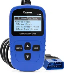
OBDII/EOBD VD31 MULTIFUNCTIONAL CODE READER
www.vdiagtool.com

Safety Information
To ensure your safety and prevent damage to the device or vehicle,
please carefully read and follow all instructions in this manual before
use.
When operating the device, always verify proper testing procedures
and strictly adhere to the instructions provided. As automotive electri-
cal systems may vary, you must assess potential risks and ensure a
safe testing environment.
Always observe all safety warnings, use appropriate tools, and discon-
nect power sources when necessary. Improper operation may result in
personal injury, equipment damage, or voided warranty.
Safety Messages
Safety messages use standardized signal words to indicate hazard
levels and prevent injuries or equipment damage:
DANGER
Will result in death or serious injury if ignored
Indicates an immediately life-threatening hazard.
WARNING
Could result in death or serious injury if ignored
Indicates a potentially dangerous situation.
Safety Instructions
This manual covers known safety hazards, but cannot anticipate all
possible risks. You are responsible for ensuring safe operating condi-
tions and procedures.
DANGER
• Always ventilate the service area when engine is running or use
building exhaust removal system if available
• Carbon monoxide is odorless and deadly - can cause loss of
consciousness or death

WARNINGS
• Always conduct testing in a safe, controlled environment.
• Wear ANSI-approved safety goggles during all operations.
• Keep all objects away from moving or hot engine components.
• Ensure proper ventilation to avoid toxic exhaust fumes.
• Secure the vehicle in PARK (automatic) or NEUTRAL (manual) with
parking brake engaged.
• Place wheel chocks and never leave the vehicle unattended during
tests.
• Exercise extreme caution around ignition systems - hazardous
voltages are present.
• Maintain an ABC-rated fire extinguisher within immediate reach.
• Never connect/disconnect test equipment with ignition on or engine
running.
• Keep all test equipment clean, dry and free from contaminants.
• Never operate test equipment while driving - focus solely on testing.
• Strictly follow the vehicle service manual's diagnostic procedures.
• Verify full battery charge and secure DLC connections before testing.
• Never place test equipment near the distributor due to EMI risks.
Legal Information
Trademarks
VDIAGTOOL is a registered trademark of Shenzhen VDIAGTOOL Tech-
nology Co., Ltd in the United States and other jurisdictions. All other
product names mentioned herein may be trademarks of their respec-
tive owners.
Copyright Information
© 2017 Shenzhen VDIAGTOOL Technology Co., Ltd. All rights
reserved.
No reproduction, distribution, or transmission of this manual is
permitted without express written authorization from VDIAGTOOL.
This prohibition applies to all forms of copying including electronic,
mechanical, photocopying, and recording.

Disclaimer & Liability Statement
Product Documentation Notice
All illustrations, specifications, and technical data in this manual are
for reference only and subject to change without notice.
For the latest documentation, visit:
https://www.vdiagtool.com/support/downloads
Limitation of Liability
VDIAGTOOL expressly disclaims all liability for:
• Any direct, indirect, incidental, or consequential damages
• Loss of profits or business interruption
• Product modifications or unauthorized use
This manual does not:
• Modify existing purchase/lease agreements
• Create additional liabilities for VDIAGTOOL
• Constitute additional product warranties
IMPORTANT:
Always consult this manual before operation, with special attention to
all safety warnings. VDIAGTOOL reserves the right to modify product
specifications at any time.
Product Support & Training Resources
Technical Support
• Official Website: www.vdiagtool.com
• Support Email: [email protected]
• US Hotline: +1-213-355-7171
• Online Form:
https://www.vdiagtool.com/support/tech-support
Training Videos
Free product operation videos:
1. Visit Training Center:
https://www.vdiagtool.com/support/training-center
2. Select Code Reader category
3. Watch model-specific tutorials

Contents
1. General Information................................................................... 1
1.1 On-Board Diagnostics(OBD) II............................................................. 1
1.2 Diagnostic Trouble Codes(DTCs)......................................................... 1
1.3 Location of the Data Link Connector DLC)..................................... 2
2. Using the Code Reader............................................................... 3
2.1 Control Buttons......................................................................................... 3
2.2 Included Accessories............................................................................... 4
2.3 Technical Specifications.......................................................................... 4
3. Getting Started............................................................................ 4
3.1 Power Connection Methods................................................................. 4
3.2 Application Overview.............................................................................. 5
4. OBDII/EOBD................................................................................. 5
4.1 Read DTC...................................................................................................... 6
4.1.1 Stored DTCs...................................................................................... 6
4.1.2 Pending DTCs.................................................................................. 6
4.1.3 Permanent DTCs............................................................................. 6
4.1.4 Stored DTC....................................................................................... 7
4.2 Clear DTC..................................................................................................... 7
4.3 Live Data...................................................................................................... 7
4.3.1 View All Items................................................................................. 8
4.3.2 Select Items...................................................................................... 8
4.3.3 View Graphic Items....................................................................... 8
4.3.4 Record All......................................................................................... 8
4.3.5 Record Select.................................................................................. 8
4.4 Freeze Frame.............................................................................................. 9
4.5 MIL Status.................................................................................................... 9
4.6 Vehicle Information............................................................................... 10
4.7 O2 Sensor.................................................................................................. 10
4.8 On-Board Monitoring (Mode 6)....................................................... 10
4.9 EVAP System Test (Mode 8)................................................................ 11
4.10 I/M Readiness........................................................................................ 12
5. Battery........................................................................................ 14
6. Key Fob Battery Check............................................................. 15
6.1 Test the New Key.................................................................................... 15
6.2 Test The Store Key.................................................................................. 15
7. DTC Lookup............................................................................... 17
8. Setting........................................................................................ 17

8.1 Language................................................................................................... 17
8.2 Unit of Measure...................................................................................... 18
8.3 Self Tests.................................................................................................... 18
8.3.1 Keys Test......................................................................................... 18
8.3.2 TFT Test........................................................................................... 18
8.3.3 LED Test........................................................................................... 19
8.4 Help............................................................................................................. 19
8.4.1 Tool Information.......................................................................... 19
8.4.2 About OBD..................................................................................... 19
8.4.3 About Datastream....................................................................... 19
8.5 Beep............................................................................................................. 19
9. Review........................................................................................ 20
10. Updating.................................................................................. 20
10.1 Updating the Code Reader.............................................................. 20
10.2 Printing.................................................................................................... 21
10.3 Manual..................................................................................................... 21
10.4 Software Language Setting............................................................. 21
11. Warranty.................................................................................. 22
12. Contact Us............................................................................... 22

1
OBDII/EOBD VD31 Multifunctional Code Reader
1. General Information
1.1 On-Board Diagnostics(OBD) II
The first generation of On-Board Diagnostics (OBD I) was introduced
by the California Air Resources Board (ARB) in 1988 to monitor basic
emission control components in vehicles. With advancements in tech-
nology and the need for enhanced diagnostics, a more sophisticated
system—OBD II—was developed.
OBD II continuously or periodically monitors emission control systems
and critical engine components through specialized tests. If an issue is
detected, the system activates a Malfunction Indicator Light (MIL) on
the dashboard, typically labeled "Check Engine" or "Service Engine
Soon."
Additionally, OBD II records essential diagnostic data to assist techni-
cians in identifying and resolving problems efficiently.
Key information includes:
• MIL Status: Whether the warning light is activated ("on") or deacti-
vated ("off").
• Diagnostic Trouble Codes (DTCs): Specific error codes stored in the
system.
• Readiness Monitor Status: The completion status of emission-re-
lated self-tests.
1.2 Diagnostic Trouble Codes(DTCs)
Diagnostic Trouble Codes (DTCs) are alphanumeric codes stored by
the vehicle’s OBD II system when a malfunction is detected. These
codes help pinpoint the source of a problem, serving as a guide for
troubleshooting.
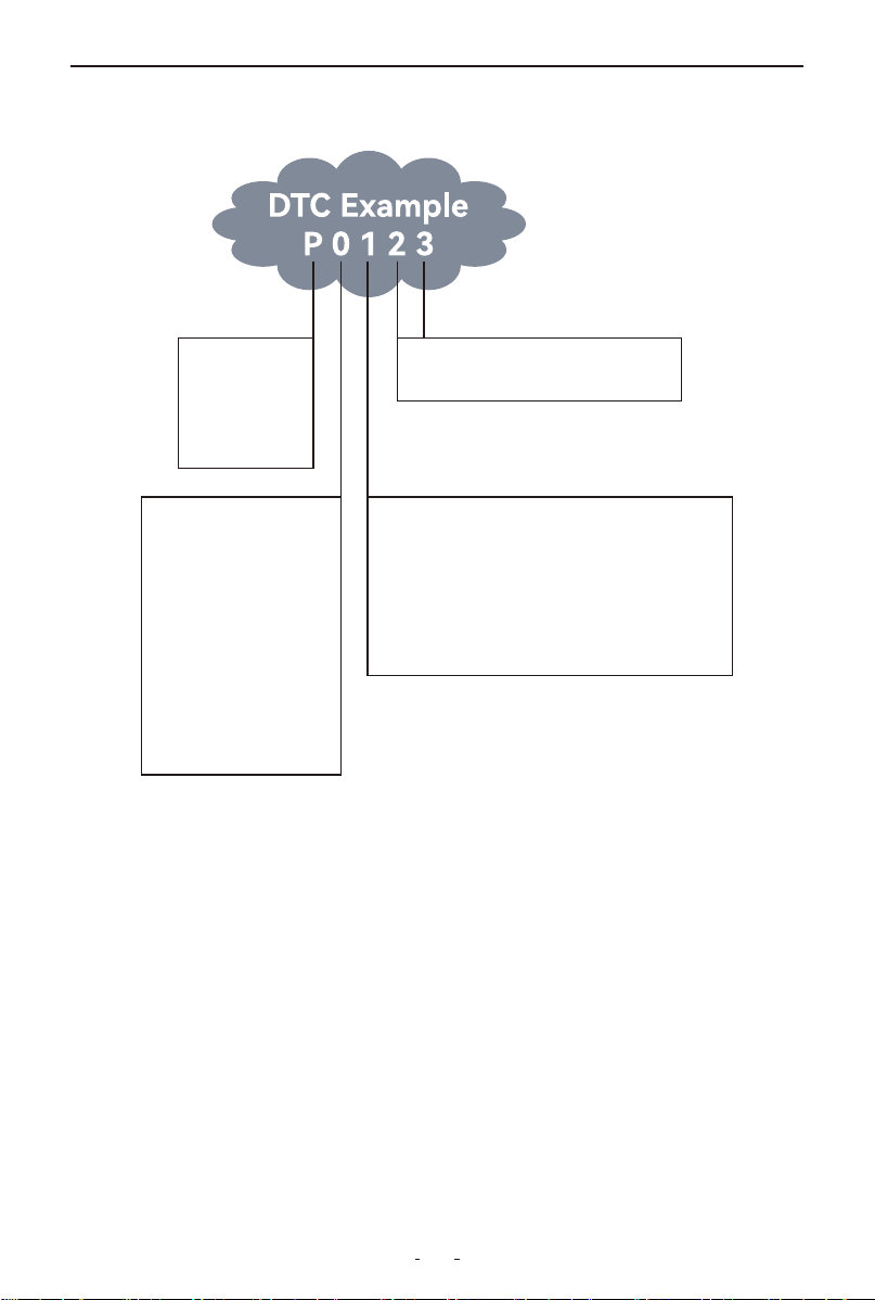
An OBD II DTC follows a 5-character format:
• First character (letter) – Indicates the affected system:
P = Powertrain (Engine/Transmission)
B = Body (e.g., Airbags, Climate Control)
C = Chassis (e.g., ABS, Stability Control)
U = Network/Communication (e.g., CAN Bus)
• Remaining four digits – Specify the exact issue
2
OBDII/EOBD VD31 Multifunctional Code Reader
Sub-systems
1 = Fuel and air metering
2 = Ignition system or engine misfire
3 = Auxiliary emissions controls
4 = Vehicle speed control and idle controls
5 = Computer output circuits
6 = Trabsnussuib cibrtiks
Systems
B = Body
C = Chassis
P = Powertrain
U = Network
Code Type
Geberuc (SAE):
P0
B0
C0
U0
Manufacturer Specific:
P1, P2
B1, B2
C1, C2
U1, U2
Last two digits identify individual
component within the system
See the following DTC breakdown for a visual explanation of how the
codes are structured.
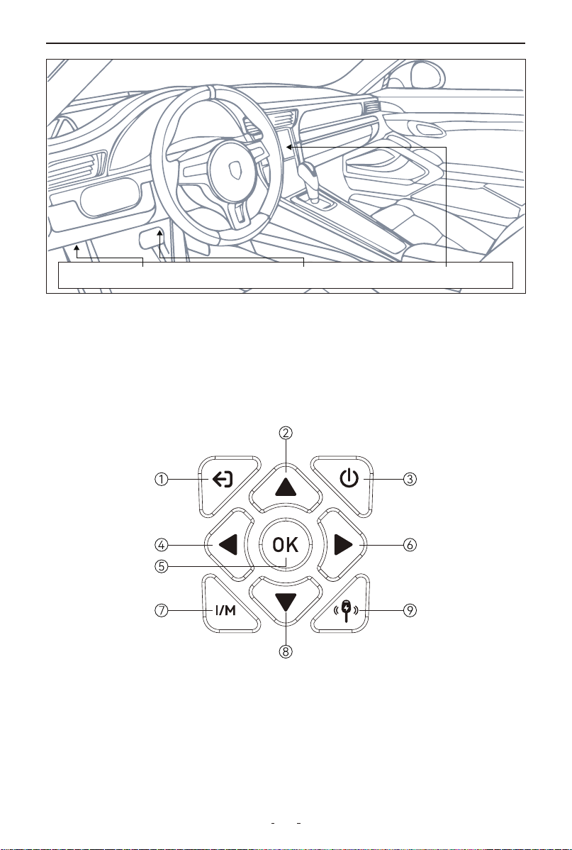
1.3 Location of the Data Link Connector (DLC)
The Data Link Connector (DLC), also known as the Diagnostic Link
Connector, is a standardized 16-pin port used to connect diagnostic
scan tools to the vehicle's onboard computer.
Typical DLC Locations:
• Most vehicles: Within 12 inches of the dashboard center, typically
under or near the driver’s side.
• Some Asian/European models: Behind the ashtray (may require
removal for access).
• If not visible: Check for a location label or consult the vehicle’s
service manual.
3
OBDII/EOBD VD31 Multifunctional Code Reader
LEFT CORNER OF DASH NEAR CENTER OF DASH BEHIND ASHTRAY
2. Using the Code Reader
This section describes the external features, ports, and connectors of
the code reader.
2.1 Control Buttons
①ESC button - Returns to previous screen (press once to exit other
tests)
②Up button - Menu navigation up; previous page in multi-screen
info; edits DTC characters
③Power button - Short press to power on; long press (3s) to power
off
④Left button - Previous page in multi-screen info

4
OBDII/EOBD VD31 Multifunctional Code Reader
⑤
OK button - Confirms selection
⑥
Right button - Next page in multi-screen info
⑦
I/M button - Checks emissions readiness and drive cycle status
⑧
Down button - Menu navigation down; next page in multi-screen
info; edits DTC characters
⑨
Key Battery button - Direct access to key battery voltage measure-
ment.
2.2 Included Accessories
• Type-C Cable: For:
- Computer connection
- Firmware updates
• User Manual: Complete operation instructions
2.3 Technical Specifications
Display: 2.8” TFT color
Operating Temperature: 0°C to 60°C (32°F to 140°F)
Storage Temperature: -20°C to 70°C (-4°F to 158°F)
Connection: Wired via main cable
Power Source: OBDII port connection, Type-C cable, or built-in 9V
battery
Compatibility: OBDII & EOBD (12V) vehicles
Dimensions: 6.5×3.54×1.18 inches
Weight: 8.47 oz
3. Getting Started
Power on your code reader by connecting to vehicle power or comput-
er before using any applications.
3.1 Power Connection Methods
Vehicle Power Connection (Recommended)
(1) Locate the vehicle's DLC (typically under dashboard)
(2) With ignition ON, connect code reader to DLC
(3) Device will auto-power on
Important:
• Never use Type-C power during vehicle communication

5
OBDII/EOBD VD31 Multifunctional Code Reader
• Ensure clean connector contact
Computer Connection (For Updates/Data Transfer)
(1) Connect Type-C cable to device and computer
(2) Device will auto-power on
Built-in 9V Battery (For Key Battery Check Only)
(1) Insert fresh 9V battery into compartment
(2) Device will auto-power on when battery is installed
3.2 Application Overview
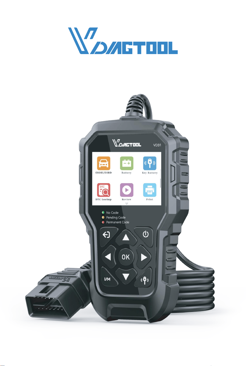
Upon startup, you'll see these preloaded applications:
• OBDII/EOBD - Shows OBDII screen for all nine OBD system tests.
• Battery - Shows screen that tests and displays voltage of vehicle
battery.
• Key Battery - Shows screen to test and display vehicle key fob
battery level.
• DTC Lookup - Shows screen for diagnostic trouble code lookup.
• Review - Shows screen for access to tested data files.
• Print - Shows screen for access to printing function.
• Setting - Shows screen for access to modify your settings like
Language, Unit of Measure, etc
4. OBDII/EOBD
When you select the OBDII/EOBD application from the home screen,
your vehicle's diagnostic information will display as shown below:
Press OK to access the diagnostic menu with these available tests:
Diagnostic Test Menu:
• Read DTC • Vehicle Info
• Clear DTC • O2 Sensor
• Live Data • Mode 6
• Freeze Frame
•
Mode 8
• MIL Status

6
OBDII/EOBD VD31 Multifunctional Code Reader
4.1 Read DTC
This function allows you to check stored fault codes in the vehicle's
control modules.
Available Code Types:
• Stored DTCs
• Pending DTCs
• Permanent DTCs
• Record DTC
4.1.1 Stored DTCs
Stored DTCs are active fault codes that are stored in the vehicle's ECU
when the onboard diagnostic system confirms a problem. These codes
will typically illuminate the check engine light (MIL) immediately upon
detection. Current DTCs can be cleared using the code reader's erase
function, though some may clear automatically after several prob-
lem-free drive cycles if the issue doesn't recur.
4.1.2 Pending DTCs
Pending DTCs are temporary fault codes stored when a potential issue
is first detected by your vehicle's monitoring systems. Unlike regular
trouble codes, these won't turn on the check engine light immediately.
The system keeps them as a warning - if the problem happens again
on your next drive, they'll turn into confirmed trouble codes and
activate the warning light. You can clear these pending codes with your
code reader, or they'll disappear automatically if the issue doesn't
recur after several driving cycles.
These codes are useful for spotting intermittent problems early or
checking if a repair fixed an issue.
4.1.3 Permanent DTCs
Permanent DTCs are fault codes that were severe enough to originally
trigger the check engine light (MIL), and remain stored in the vehicle's
computer even after the light turns off. These codes preserve a record
of the fault whether the MIL was cleared manually or stopped illumi-
nating because the problem didn't reoccur. They automatically erase
only after: (1) the underlying issue is fully repaired, and (2) the system
successfully completes 3 consecutive drive cycles without detecting
the fault.

7
OBDII/EOBD VD31 Multifunctional Code Reader
4.1.4 Record DTC
This function allows you to record the DTCs if there are trouble codes
in the vehicle.
To read codes from a vehicle:
(1) Select "Read DTC" from the OBDII/EOBD menu using the arrow
keys, then press OK.
(2) Choose the code type (Stored, Pending, or Permanent DTCs) and
confirm with OK.
(3) The tool will display all detected codes along with their descrip-
tions.
4.2 Clear DTC
This function allows you to clear stored diagnostic trouble codes
(DTCs) from the vehicle's ECU with the ignition ON (engine OFF).
To erase codes from a vehicle:
(1) Select "Clear DTC" from the OBDII menu.
(2) Follow the on-screen prompts to confirm and complete the
erasure.
(3) Immediately rescan the system to check for remaining codes.
After Erasure:
If codes persist: This may indicate permanent DTCs. Please repair or
replace the affected components before attempting to clear the codes
again.
4.3 Live Data
This function allows real-time monitoring of vehicle sensor data and
system parameters (PIDs) from the ECU.
• View All Items
• Select Items
• View Graphic Items
• Record All
• Record Select

8
OBDII/EOBD VD31 Multifunctional Code Reader
View Graphic Items
max 0 0 00.0
mix 0 0 00.0
MIL-DIST=0miles
WARM-UPS=0
EVAP-PCT=0.0%
CLR-DIST=0miles
4.3.1 View All Items
This function displays real-time monitoring of all available vehicle
parameters from the ECU, including engine RPM, coolant tempera-
ture, fuel trim values (both short-term and long-term), oxygen sensor
voltages, throttle position, and other critical system measurements.
4.3.2 Select Items
This function enables focused monitoring of specific vehicle parame-
ters.
To view selected PIDs:
(1) Navigate through the parameter list using the UP/DOWN button
(2) Press OK to select/deselect each desired parameter
(3) Press ESC to display all selected parameters in real-time
4.3.3 View Graphic Items
This function allows you to view the PID data as a graphing.
4.3.4 Record All
This function is used to record PIDs to help diagnose intermittent
drivability problems that can’t be determined by any other method.
4.3.5 Record Select
This function allows you to record the PID data you selected.
CAUTION
• Always park the vehicle before using the code reader

9
OBDII/EOBD VD31 Multifunctional Code Reader
MIL Status
< 1/2 >
Check Engine Light Status
OFF
Run Time with Check Engine Light On
-
Day
-
Hours
-
Minutes
Distance with Check Engine Light On
0
KM
0.00
Miles
• When recording live data during driving, ensure two occupants are
present - one to drive and one to operate the device
NOTE:
Vehicle communication speeds and supported PIDs vary by make/-
model/year. Some parameters may not be available on all vehicles.
4.4 Freeze Frame
The Freeze Frame function provides a snapshot of critical vehicle
parameters (engine RPM, load, fuel system status, etc.) recorded at the
moment a fault code was triggered. This data helps diagnose intermit-
tent issues by showing exact operating conditions when the problem
occurred.
To access freeze frame Data:
(1) Select Freeze Frame from the OBDII menu
(2) Scroll through recorded parameters using UP/DOWN button
(3) View detailed condition readings for each parameter
Note: If no data is available, the display will show "No freeze frame
data stored"
4.5 MIL Status
Performing MIL status function, it will show you some detailed infor-
mation, such as the Check Engine Light status, the Run Time with
Check Engine Light on, the Distance with Check Engine Light on and
etc.

10
OBDII/EOBD VD31 Multifunctional Code Reader
4.6 Vehicle Information
The Vehicle Information function retrieves the vehicle's VIN number,
calibration IDs (identifying control module software versions), and
calibration verification numbers (CVNs), which are values calculated
according to OBDII regulations to verify whether emission-related
calibrations have been modified.
Note that multiple CVNs may be reported for a single control module
and the calculation process may take several minutes to complete.
Available options will vary depending on the connected vehicle.
4.7 O2 Sensor
O2 Sensor Test opens a menu of tests available for checking the integ-
rity of the oxygen sensors.
Making a selection displays all of the pertinent O2S parameters for the
specific test.
4.8 On-Board Monitoring (Mode 6)
The On-Board Monitoring(Mode 6) function is useful after servicing or
after clearing a vehicle ECU's memory. It receives test results for emis-
sion-related powertrain components and systems that are not contin-
uously monitored for Non-CAN vehicles. And for CAN vehicles, it
receives test data for emission-related powertrain components and
systems that are and are not continuously monitored. It is vehicle man-
ufacturer who is responsible for assigning test and component IDs.
NOTE:
Test results do not necessarily indicate a faulty component or system.
To request On-board Monitor Test (Mode 6) results:
(1) Use the UP/DOWN key to highlight On-board Monitor Test(-
Mode 6) from OBDII/EOBD menu and press the OK key.
(2) A screen will show:

11
OBDII/EOBD VD31 Multifunctional Code Reader
On-Board Monitoring
Catalyst Monitor B1
VVT Monitor Bank 1
Sensor Heater B1-S1
Sensor Heater B1-S2
Misfire Cylinder 1
Misfire Cylinder 2
Misfire Cylinder 3
Misfire Cylinder 4
(3) Use the UP/DOWN key to highlight a test group and press the OK
key to confirm, a screen with details of the selected sensor displays.
Use the UP/DOWN arrow keys to scroll through data to select lines.
4.9 EVAP System Test (Mode 8)
The EVAP System Test (Mode 8) allows the code reader to control
operation of vehicle components, tests of systems.
EVAP(Evaporative Emission Control System) is an automotive system
designed to prevent fuel vapor from escaping into the atmosphere,
thereby reducing air pollution.
Its main functions include:
(1) Preventing Fuel Vapor Leakage: The EVAP system captures and
stores fuel vapor to avoid its escape into the environment while the
vehicle is in operation or parked.
(2) Storing Vapor: The system uses a fuel vapor canister to store
vapors, minimizing their impact on the environment.
(3) Recycling Vapor: When the engine is running, the system directs
the stored vapor back to the combustion chamber via an electromag-
netic valve for re-burning, enhancing fuel efficiency.
(4) Monitoring for Leaks: The EVAP system is equipped with sensors
that monitor pressure changes in real-time to detect any leaks within
the system, ensuring its integrity.

12
OBDII/EOBD VD31 Multifunctional Code Reader
(5) Improving Fuel Efficiency: By effectively capturing and reusing fuel
vapor, the EVAP system contributes to improved fuel economy and
reduced fuel consumption.
NOTE:
• Some manufactures do not allow tools to control vehicle systems.
• The manufacturer sets the criteria to automatically stop test. Refer to
appropriate vehicle service manual before using this function.
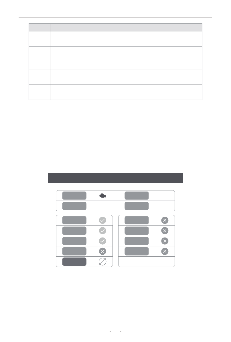
4.10 I/M Readiness
I/M Readiness, or Inspection and Maintenance Readiness, refers to the
status of a vehicle's on-board diagnostic (OBD) system's readiness to
perform emissions testing. It indicates whether the various emis-
sions-related systems on the vehicle are operating properly and have
completed their self-diagnostic checks. This is crucial for passing state
emissions inspections, as some monitors must be "ready" for the
vehicle to be compliant.
Monitor Status:
• OK - Test completed successfully
• INC (Incomplete) - Test not yet finished (needs more driving)
• N/A (Not Applicable) - This monitor is not required/supported for
your specific vehicle
There are two types of I/M Readiness tests:
• Since DTCs Cleared - shows the status of monitors since the last
time diagnostic trouble codes (DTCs) were cleared.
• This Drive Cycle - shows the status of monitors since the beginning
of the current driving cycle.
The code reader supports these standard OBDII monitor abbreviations
and full names:
13
OBDII/EOBD VD31 Multifunctional Code Reader
No Abbreviation Name
1 MIS Misfire Monitor
2 FUEL Fuel System Monitor
3 CCM Comprehensive Components Monitor
4 CAT Catalyst Monitor
5 HCAT Heated Catalyst Monitor
6 EVAP Evaporative System Monitor
7 AIR Air Conditioning Refrigerant Monitor
8 O2S Oxygen Sensor Monitor
9 HTR Oxygen Sensor Heater Monitor
I/M Readiness
MIS EVAP
DTC 0 Pd DTC 3
MIL IGN ComPr
FUE AIR
CCM O2S
CAT HRT
HCAT
NOTE:
• To check I/M Readiness status, ensure the ignition is ON (engine
OFF)
• Monitor availability varies by vehicle specifications.
To retrieve I/M Readiness Status data by one-click I/M Readiness
hotkey:
(1) Press the I/M Readiness hot key on the keypad and the following
screen displays:
(2) Colored LED and build-in beeper provide both visual and audible
reminders for emission check and DTCs.

14
OBDII/EOBD VD31 Multifunctional Code Reader
Battery
Battery Volt
12.1V
Normal battery voltage, good
battery status.
When the LED is:
• Yellow - The tool finds a possible problem. It indicates the following
two conditions:
(1) Pending DTCs exist. Please check the I/M Readiness test result
screen and use the Read Codes function to view detailed codes infor-
mation.
(2) Some of the vehicle's emission monitors have not working proper-
ly. If the I/M Readiness screen shows no DTC(including pending DTC),
but the Yellow LED is still illuminated, it indicate a "Monitor Has Not
Run" status.
• Red - Indicates some problems exist with one or more of the
vehicle's system, and the vehicle is not ready for an Emissions Test. As
well there are DTCs found. The MIL lamp on the vehicle's instrument
panel will light steady. The problem that is causing the illumination of
Red LED should be fixed before an Emissions Test or driving the
vehicle further.
NOTE:
The built-in beeper which makes different tones corresponding to
different LED indicators is invaluable when the test is performed while
driving or in bright areas where LED illumination may not be visible.
5. Battery
This function provides real-time battery voltage monitoring.

15
OBDII/EOBD VD31 Multifunctional Code Reader
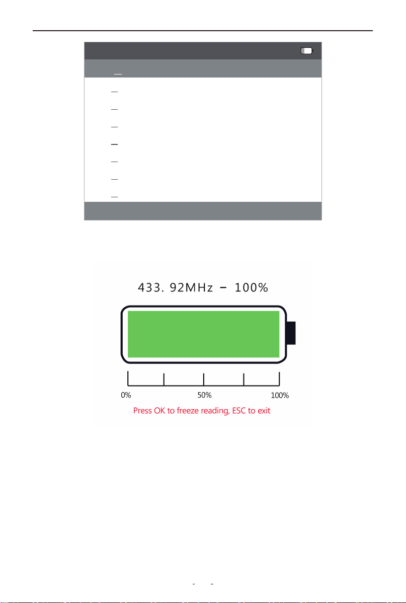
6. Key Fob Battery Check
The device displays the installed 9V battery level in the top-right
corner.
6.1 Test the New Key
For first-time use, select Test The New Key to add the test key.
New Key Identification Methods
• Brand Selection
For more accurate key battery level testing, select your vehicle brand
directly. This method skips manual scanning by leveraging pre-config-
ured frequency data tailored to your car model, ensuring higher detec-
tion accuracy for key battery status.
How to Use:
(1) Navigate to Brand Selection in the menu.
(2) Choose your vehicle manufacturer from the list.
(3) Follow on-screen prompts (e.g., press the key button) to test the
battery.
• Automatic Scan
(1) Position the key in the device's top-left sensing area (align with
signal icon)
(2) Press key function button every 3 seconds until success message
appears
• Frequency Selection
(1) Adjust frequency value:
- Up/Down buttons: Change digit value
- Left/Right buttons: Move cursor position
(2) Press OK to confirm when "Scan successful" appears
6.2 Test The Store Key
Successfully tested keys are automatically saved in the stored key
menu for future testing, eliminating the need for re-identification.
16
OBDII/EOBD VD31 Multifunctional Code Reader
You can test or delete stored keys by pressing OK.
Below is the test result screen for reference:
Note:
It is recommended to press the OK button to freeze the reading when
the key battery level is read, because if the key is accidentally moved,
the test result may become 0%. Of course, you can put the key close
to the sensing area again, and then press the function key (lock or
unlock), and the reading will appear again. After pressing the OK
button, if you want to re-measure, press ESC to exit and re-measure.
If you have any questions or need assitance, feel free to contact our
support team at [email protected].
List of keys
Key 1-433.92MHz
Key 2 -433.92MHz
Key 3 -433.92MHz
Key 4 -433.92MHz
Key 5 -434MHz
Key 6 -433MHz
Key 7 -433.92MHz
Key 8 -433.92MHz
1/2
>
>

17
OBDII/EOBD VD31 Multifunctional Code Reader
7. DTC Lookup
This function provides instant access to the built-in diagnostic trouble
code database, containing both SAE standard and manufacturer-spe-
cific code definitions.
To Search for DTC Definitions:
(1) Select DTC Lookup from the main menu
(2) Enter the code using:
• LEFT/RIGHT to navigate character positions
• UP/DOWN to change digit values
• OK to confirm
(3) View the code definition
Note:
• For manufacturer-specific codes (P1xxx/C1xxx/B1xxx/U1xxx), select
the vehicle make
• If no definition is found, consult the vehicle service manual
8. Setting
This menu allows you to customize the code reader's configuration to
suit your preferences.
Available Options:
• Language - Select display language
• Unit of Measure - Choose metric/imperial units
• Self Tests - Run device self-test
• Help - Access device information
• Beep - Turn beep on or off
8.1 Language
Selecting Language opens a screen that allows you to choose system
language.
To configure system language:
(1) Select Language from the Settings menu
(2) Choose your desired language from the available list
(3) Confirm selection with OK

18
OBDII/EOBD VD31 Multifunctional Code Reader
8.2 Unit of Measure
This setting allows you to switch between measurement systems:
Available Options:
• Metric (km/h, °C)
• US Customary (mph, °F)
Configuration Steps:
(1) Select Unit of Measure from the Settings menu
(2) Choose preferred system
(3) Confirm with OK
8.3 Self Tests
This feature verifies proper operation of the device hardware compo-
nents.
Available Tests:
• Keys Test
• TFT Test
• LED Test
8.3.1 Keys Test
Selecting Keys Test option opens a screen that allows you to check the
functionality of the keypad.
To test the keypad:
(1) Select Key Test from Self-Test menu
(2) Press any button - the display will show button name
(3) Double-press ESC to exit
8.3.2 TFT Test
Selecting TFT Test option opens a screen that allows you to check the
functionality of the screen.
To test the screen:
(1) Select TFT Test
(2) Visually inspect for:
• Dead pixels
• Color uniformity

19
OBDII/EOBD VD31 Multifunctional Code Reader
(3) Press ESC to complete
8.3.3 LED Test
Selecting LED Test option opens a screen that allows you to check the
functionality of the LED.
To test the LED:
(1) Select LED Test
(2) All status LEDs will illuminate sequentially
(3) Press ESC to terminate
8.4 Help
Access this section for essential product information and diagnostic
references.
Available Resources:
• Device Information
• About OBD
• About Data Stream
8.4.1 Tool Information
This option will show information about your code reader, such as
hardware and software version.
8.4.2 About OBD
This option will show you what is OBD, OBDII modes and vehicle
coverage.
8.4.3 About Datastream
This option will show you some brief introductions about each sensor
and module.
8.5 Beep
Opens a settings dialog to enable/disable the keypress sound from the
built-in speaker.
20
OBDII/EOBD VD31 Multifunctional Code Reader
VDLINK_V24.07
Manual
Upgrade
Print
EnglishLanguage:
Clear message Upgrade
Prompt messages:
1. The device must enter the upgrade mode
2. To enter the upgrade mode:
3. Press and hold down the arrow key of the diagnostic device (the device does not need to be connected to the OBD port and USB port).
4. Hold down the Down arrow key and use the USB cable to connect the diagnostic device to the computer
5. Wait until UPDATE MODE is displayed on the device screen, and release the arrow key Down. The device enters the upgrade mode successfully
6. Click the upgrade button in the lower right corner
Port:
9. Review
This fun ction provides access to all recorded diagnostic data through
the following menu options:
• Review DTC
• Review Datastream
• Review Freeze Frame
• Delete DTC Data
• Delete Datastream
• Delete Freeze Frame
To review or delete recorded data:
(1) Select Review from the main menu
(2) Navigate through the six options using UP/DOWN button
(3) Press OK to view or delete selected data
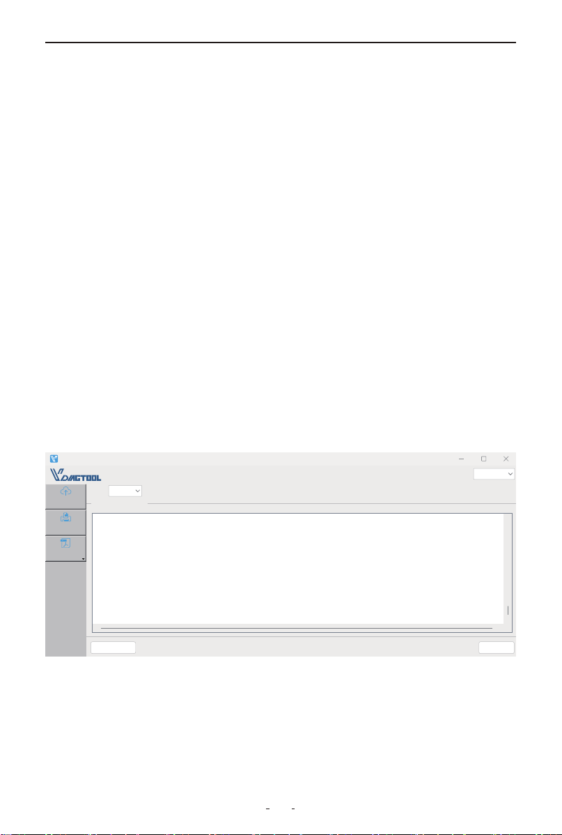
10. Updating
10.1 Updating the Code Reader
(1) Download and install the VD31 Update Client from
https://www.vdiagtool.com/support/downloads.
(2) Launch the VD31 Update Client.
(3) With the device powered off, hold the Down button while connect-
ing via USB-C until "UPDATE MODE" appears.
(4) Click Upgrade and wait for completion.
21
OBDII/EOBD VD31 Multifunctional Code Reader
VDLINK_V24.07
Manual
Upgrade
Print
Language:
Po:
Clear message Upgrade
Prompt messages:
1. The device must enter the upgrade mode
2. To enter the upgrade mode:
3. Press and hold down the arrow key of the diagnostic device (the device does not need to be connected to the OBD po and USB po).
4. Hold down the Down arrow key and use the USB cable to connect the diagnostic device to the computer
5. Wait until UPDATE MODE is displayed on the device screen, and release the arrow key Down. The device enters the upgrade mode successfully
6. Click the upgrade button in the lower right corner
English
English
Français
Čeština
Türkçe
Español
Deutsch
Italiano
Polski
Русский
Pouguês
10.2 Printing
This function transfers saved diagnostic data to your computer as a
.txt file for printing.
(1) Open the VD30 Pro software and connect the device to your com-
puter and
(2) Click Print in the software
(3) On the device, select the test results to print and confirm
(4) The data will transfer as a .txt file
(5) Click Open File in the software to locate and print the report
10.3 Manual
A copy of user manual in PDF format will show up when you click this
option.
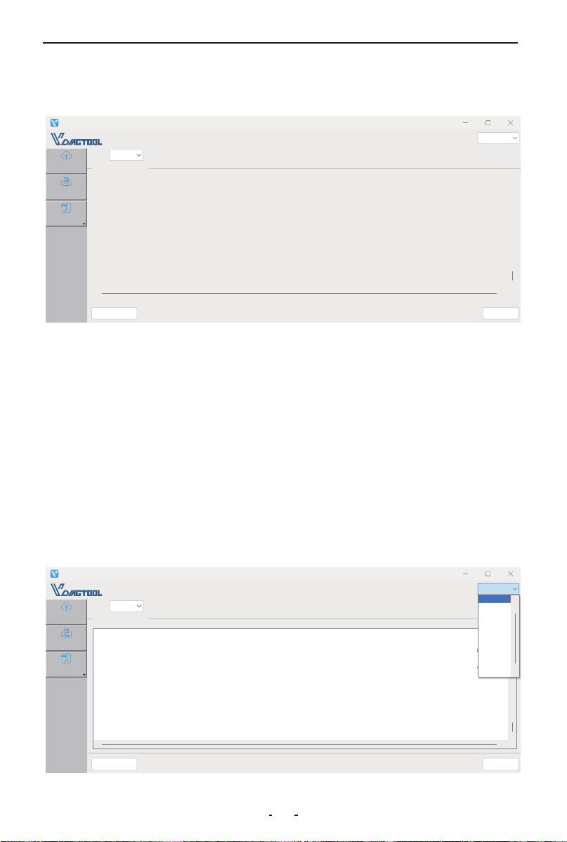
10.4 Software Language Setting
This option allows you to set the language of the update client.
VDLINK_V24.07
Manual
Upgrade
Print
EnglishLanguage:
Port:
Clear message Upgrade
Prompt messages:
1. When printing, make sure the device is properly connected to the computer.
2. Power on the device and access the print function.
3. On the device Print page, select the required data.
4. The device will send data to the computer software.

22
OBDII/EOBD VD31 Multifunctional Code Reader
11. Warranty
Limited Three Years Warranty
This warranty is expressly limited to buyer who purchase VDIAGTOOL
VD31 product for purposes of resale or use in the ordinary course of
the buyer’s business.
VDIAGTOOL VD31 is warranted against defects in materials and work-
manship for three years(36 months) from date of delivery to the buyer.
This warranty does not cover any part that has been abused, altered,
used for a purpose other than for which it was intended, or used in a
manner inconsistent with instructions regarding use. The exclusive
remedy for any tool found to be defective is repair or replacement, and
it shall not be liable for any consequential or incidental damages.
12. Contact Us
Warranty & Support
Email: [email protected]
Website: www.vdiagtool.com
For wholesale business or become our distributors:
Email: [email protected]
Invent with us, test products before they hit market, help us make
better products for everyone:
Email: [email protected]
Create social media content, post online and help our community:
Email: [email protected]
Follow Us on Social Media

23
OBDII/EOBD VD31 Multifunctional Code Reader
Facebook Page: Search for "vdiagtool"
Facebook User Group: Search for "VDIAGTOOL OFFICIAL User Group"
Instagram: Search for "vdiagtool_official"
TikTok: Search for "vdiagtool_us"
YouTube: Search for "Vdiagtool Official"