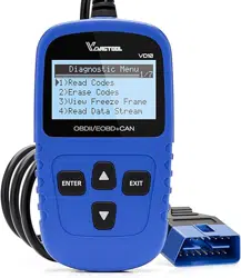
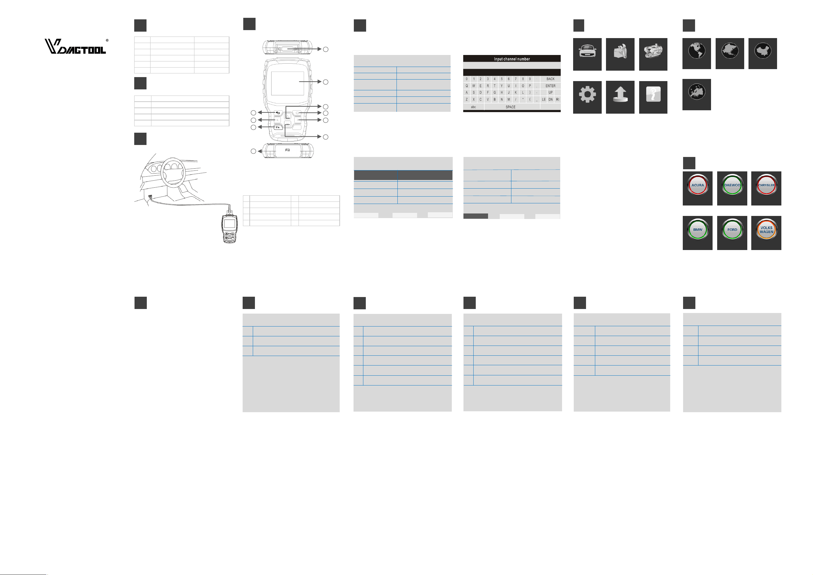
1 Screen Display 3.5“ Color
2 Dimension (LxWxH) 24x16x11cm
3 Gross Weight 0.85kg
4 OS Platform Linux
5 Card Memory 16G
6 Input Voltage DC 12V
FN Key ( 3-in-1 Functions defined) Port Definition & Keys Definitions
1 For main cable connection 2 3.5” color display
3 Up button 4 OK button
5 Right button 6 Down button
7 For USB cable connection 8 FN key
9 Left button 10 ESC button
SHENZHEN CHUANG XIN HONG TECHNOLOGY CO.,LTD
Room 703, Block A, Zaoan Business Building, Shigu
Road ,Xili Street, Nanshan District, Shenzhen, China
Tel: +86 755 2675 1057
Email: vdiagto[email protected]
Http://www.vdiagtool.com
VT00 Auto Scanner User Manual
1 Nylon tool bag
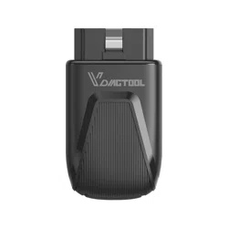
2 VT100 main unit
3 Main cable with OBDII-16
4 USB cable
5 User Manual
Technical Specifications
1
4
Standard Accessory Kits
2
5
Cable Connection for On-Board Diagnosis
3
Main Menu
Settings To provide the system setting, including Language ,
logging, unit setting and Bluetooth setting.
Diagnose To access specific diagnosis function directly base on
selection of the areas as well as the car makes
Special
Functions
To provide 5 common use service resets for the
professional workshop repairs.
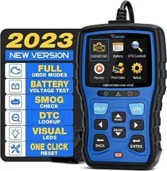
OBDII
V3.0
10 modes of OBDII test for cars after1996 and newer
including read/erase codes, view live data, view freeze
frame data, view I/M readiness, O2 monitor test etc.
6
√
√
IGN RUN START SW
IGN STSRT SW
MAP Vacuum
Map Volts
On
Off
0.00 (in Hg)
4.92 (Volts)
Ignition Start Switch Filter Off
FN #1 : Selection
Press FN key to select the items in live data function.
After pressing OK, the live data will be displayed in graphic.
Auto Shutdown (ASD) Relay
Auto Shutdown (ASD)
Relay Control State
Off F1
BACK
F2
On F2
F3
Toggle
F1
FN #2 : Show/Hide keyboard
Press FN key to show or hide the keyboard
FN #3: Shift operation area
Different operation areas can be switched among each other by pressing the FN key during the special testing.
Auto Shutdown (ASD) Relay
Off F1
BACK F1
F2
On F2
F3
Toggle
Auto Shutdown (ASD)
Relay Control State
Press FN key, the display area will be highlighted as above,
Press the up and down button to view more information.
Press FN key, the function area will be highlighted as above,
Press the left and right button to actuate more test.
Diagnose - Function Selection Diagnose - ECU Information
13
Diagnose - Read Fault Code
14
Diagnose - Vehicle Identification
10
CHRYSLE
1
2
Automatic selection
Manual selection
12
Powertrain Control Module
1
2
3
4
Computer identification
Read fault code
Clear fault code
Read data stream
Vehicle Information
Model Year
ECU Part No.
Body Style
Vehicle Line
VIN-Original
2010.00
68045613AE
Station Wagon
RT
2D4RN4DE0AR
473865
Fault code list
P0522
U0141
P0685
P0627
Engine Oil Pressure Sensor
Low Communication with IPM
(FCM/TIPM) [Active]
ASD/Main Control Circuit [Active]
Fuel Pump Control Circuit/open
1. Automatic selection
The diagnostic system features the latest VIN-based Auto VIN
Scan function to identify CAN vehicles in just one touch, which
allows the technician to quickly detect vehicles, scan all the
diagnosable ECUs on every vehicle and run diagnostics on the
selected system.
2. Manual selection
This mode of vehicle selection is menu driven; you can make a
series of choices, Each selection you make advances you to the
next screen. A Back button returns you to the previous screen.
Exact procedures may vary somewhat by various vehicles being
serviced.
The Function Menu options vary slightly for different vehicles. The
function menu may include:
1. Computer identification — provides the retrieved ECU infor-
mation in detail. An information screen opens upon selection.
2. Read fault code — displays detailed information of DTC records
retrieved from the vehicle control module.
3. Clear fault code — erases DTC records and other data from the
test vehicle’s ECU.
4. Read data stream — retrieves and displays data stream and
parameters from the vehicle’s ECU.
The function retrieves and displays the specific information for
the tested control unit, including unit type, version numbers and
other specifications. The sample Vehicle Information screen
displays as above.
During an active test, the tester outputs commands to the ECU in
order to drive the actuators. This test determines the integrity of
the system or parts by reading the engine ECU data, or by
monitoring the operation of the actuators, such as switching a
solenoid, relay, or switch, between two operating states.
This function retrieves and displays the DTCs from the vehicle’s
control system. The Fault code list screen varies for each vehicle
being tested. On some vehicles, freeze frame data can also be
retrieved for viewing. The sample Read Codes screen displays as
above.
Settings
Diagnose Special Functions OBDII V3.0
Diagnose - Region Selection
7
American Asian Chinese
European
BMW
Acura Daewoo Chrysler
Ford Volkswagen
Diagnose - Vehicle Coverage
8
Connection To connect the main unit with the main cable
To get power supply from the car via OBDII-16
connector
European
American
Asian
Chinese
Vehicle coverage:
BMW, MERCEDES-BENZ, CITROEN, PEUGEOT, VOLVO,
LANDROVER, JAGUAR, FIAT, OPEL, VAUXHALL, AUDI,
VOLKSWAGEN, RENAULT, etc
Vehicle coverage:
GM, FORD, CHRYSLER
Vehicle coverage:
TOYOTA, LEXUS, HONDA, ACURA, NISSAN, INFINITI,
HYUNDAI, KIA, MITSUBISHI, ISUZU, SUZUKI, MAZDA,
SUBARU, etc
Vehicle coverage:
BYD, CHANA, CHEYR, GEELY, GWM, LIFAN, etc
Diagnose - Vehicle Coverage
9
Please note that the VT100 is a vehicle-specific car diagnostic tool.
Therefore, it only supports vehicles of a specific car group, which
depends on the pre-installed car brand software. For the blank version
machine, please contact us to install your selected car brand software.
Diagnose - Control Unit
11
Control Unit
1
2
3
4
Powertrain Control Module
Transmission Control Module
Anti Lock Brakes
AirBag
Update About
About To provide the system information menu.
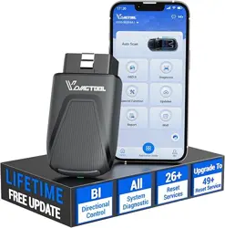
Update To access online software update for full coverage.
Internet update via WI-FI
4
3
5
6
7
10
8
9
1
2
This option allows you to manually locate a required control system
for testing through a series of choices. Follow the menu driven
procedures and make proper selections; the application will guide
you to the diagnostic function menu after a few choices you’re
made.
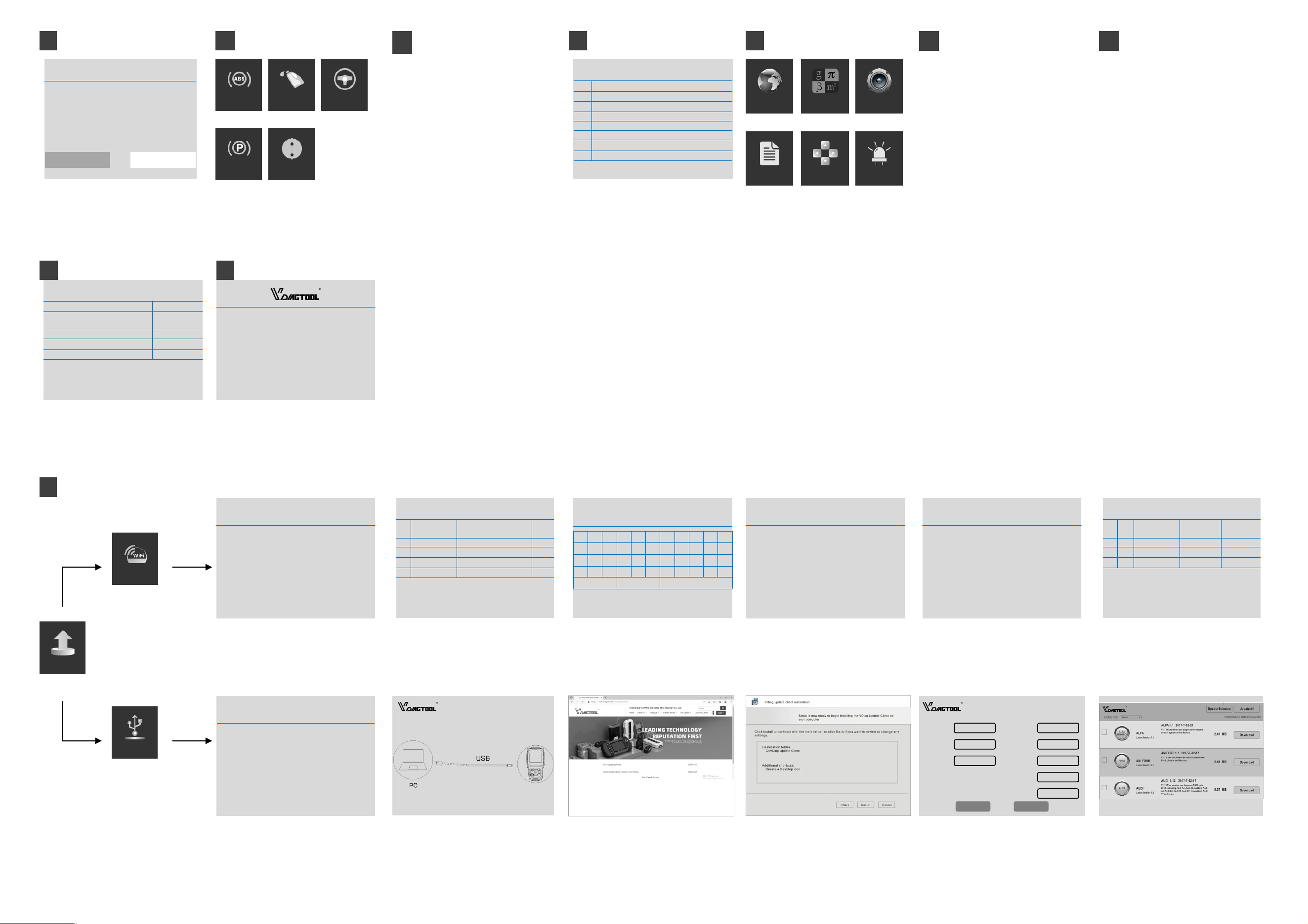
Oil Light Reset
This function allows you to perform reset for the Engine Oil Life
system, which calculations
An optional oil life change interval depending on the vehicle
driving conditions and climates. The Oil Life Reminder must be
reset every time the oil is changed, so the system can calculate
when the next oil change is required.
EPB Reset
This function has a multitude of usages to maintain the elec-
tronic braking system safely and effectively. The applications
include deactivating and activating the brake control system,
assisting with brake fluid control, opening and closing brake
pads, and setting brakes after disc or pad replacement, etc
ABS Bleeding
This function allows you to perform various bi-directional tests
to check the operating conditions of Anti-lock Braking System
(ABS). 1. When the ABS contains air, the ABS bleeding function
must be performed to bleed the brake system to restore ABS
brake sensitivity. 2. If the ABS computer, ABS pump, brake
master cylinder, brake cylinder, brake line, or brake fluid is
replaced, the ABS bleeding function must be performed to
bleed the ABS.
Throttle Relearn
This function enables you to make initial settings to throttle
actuators and returns the “learned” values stored on ECU to the
default state. Doing so can accurately control the actions of
regulating throttle (or idle engine) to adjust the amount of air
intake.
SAS Reset
To reset the steering angle, first find the relative zero point
position for the car to drive in straight line. Taking this position
as reference, the ECU can calculate the accurate angle for left
and right steering. After replacing the steering angle position
sensor, replacing steering mechanical parts (such as steering
gearbox, steering column, end tie rod, steering knuckle),
performing four-wheel alignment, or recovering car body, you
must reset the steering angle.
Definition of Special Function
18
Diagnose - Clear fault code
15
Do you want to erase all the fault
code (s)?
Information
Yes No
After reading the retrieved codes and making appropriate
vehicle repairs, use this function to clear fault code.
Special Function
17
Diagnose - DataStream
16
CHRYSLER
Current Fuel Shutoff
SKIM VTA Invalid Key
Received Fault Posted
NGC Should Shut Off Fuel
ASD
False
Fuel On
SKIM/VATA Has Completed False
IGN RUN START SW On
When this function is selected, the screen displays the data list for
the selected module. The items available for any control module
vary by vehicle. The parameters display in the order that they are
transmitted by the ECM, so expect variation between vehicles.
OBDII Function
20
This section describes the various functions of each option:
1. Stored codes are the current emission-related DTCs from the
ECM of the vehicle. OBD II/EOBD Codes have a priority according
to their emission severity, with higher priority codes overwriting
lower priority codes.
2.This option is used to clear all emission-related diagnostic data
such as, DTCs, Freeze frame data and manufacturer-specific
enhanced data from the vehicle’s ECM, and reset the I/M Readi-
ness Monitor Status for all vehicle’s ECM.
3.This function displays the real time PID data from ECU. Dis-
played data includes analog inputs and outputs, digital inputs
and outputs, and system status information broadcast on the
vehicle data stream.
4. These are codes that were generated during the last drive
cycle, but before the DTC actually sets, two or more consecutive
drive cycles are needed. The service is to assist the service
technician after a vehicle repair and after clearing diagnostic
information, by expect or see differences between makes.
5. Typically, the stored frame is the last DTC that occurred. Certain
DTCs that have a greater impact on vehicle emission, have a
higher priority. The top prioritized DTC is the one for which the
freeze frame records are retained.
6. This function is used to check the readiness of the monitoring
system. It is an excellent function to use prior to having a vehicle
inspected for state emissions compliance. Select I/M readiness to
display a sub menu with two choice.
7. Use this option to view the result of On-Board Monitor tests.
The tests are useful after servicing or after erasing a vehicle’s
control module memory.
8. The option displays the vehicle identification number (VIN), the
Please Select the Nameplate:
[1] Read Current Trouble Code
[2] Clear Trouble Code
[3] Read Current Data
[4] Read Pending Trouble Code
[5] Read Freeze Frame Data
[6] Readiness Tests
[7] On-Board Monitoring Test
[8] Read System Information
Setting
21
Record
Language
Unit
Beep
Display record setting menu.
Record includes: On and Off.
Press OK to change the record setting selection.
This function allows data recording during the
Display multi-languages function menu.
Total 18 languages optional. Only 2 languages
loaded before delivery: English + local language
Display unit setting menu.
Unit includes: Metric and English units.
Press OK to change the unit setting selection.
Display beep setting menu.
Beep includes: On and Off.
Press OK to change the beep setting selection.
Button Test
LCD Test
Display button function menu.
Press the FN key for 2 seconds to quit the
button test.
Display LCD test function menu.
Press ESC to quit the LCD test.
Record
Language Unit Beep
Button Test LCD Test
Why cannot install VDiagtool Update client correctly?
After installing the VDiagtool Update Client software, the
system won’t accept the serial number for the auto scanner.
Note: You need to connect auto scanner to PC with the USB
cable before software download.
Why the vehicle linking error ?
A communication error occurs if the auto scanner fails to
communicate with
the vehicle ECU. Follow the steps to check the connections:
1– Verify the ignition is ON.
2– Check the cable or connector is securely connected t the
vehicle DLC.
3– Turn the ignition off and wait for about 10 seconds and
turn the ignition back to ON and continue the testing.
4– Verify the control module is not defective.
Why the device doesn’t power up ?
If the auto scanner won’t power up or operate correctly in
any other way, follow the steps to check the connections:
1– Check the connector properly inserted to the socket seat.
2– Check the DLC pins bent or broken.
3– Clean the DLC pins if necessary.
Why the device have no permission to update?
Please contact the local distributor to get authorization.
Why cannot find the WIFI name ?
The device can only display the Wifi name consisting of
English character or numbers.
12-Month Limited Warranty
VDiagTool warrants to the original retail purchaser of this
VT100 auto scanner, that should this product or any part
thereof during normal consumer usage and conditions, be
proven defective in material or workmanship that results in
product failure within twelve (12) months period from the
date of delivery, such defects will be repaired, or replaced
(with new or rebuilt parts) with Proof of Purchase, at the
Company’s option, without charge for parts or labor directly
related to the defects.
The Company shall not be liable for any incidental or
consequential damages arising from the use, misuse, or
mounting of the auto scanner. Some states do not allow
limitation on how long an implied warranty lasts, so the above
limitations may not apply to you.
This warranty does not apply to:
A) Product subject to abnormal use or conditions,
accident, mishandling, neglect, unauthorized
alternation, misuse, improper installation or repair or
improper storage;
B) Products whose mechanical serial number or
electronic serial number has been removed, altered
or defected;
C) Damage from expose to excessive temperatures or
extreme environmental conditions;
D) Damage resulting from connection to, or use of any
accessory or other product not approved or author-
ized by the Company;
E) Defects in appearance, cosmetic, decorative or
structural items such as framing and non operative
parts;
F) Product damaged from external causes such as fire,
dirt, sand, battery leakage, blown fuse, theft or
improper usage of any electrical source.
IMPORTANT: All contents of the product may be deleted
during the process of repair. You should create a back-up
copy of any contents of your product before delivering the
product for warranty service.
FAQ
22
Warranty
23
About
19
Product Serial Number: VT1000002
Register Password: VTTXCN02
Firmware Version: 7001.7048
System Software Version: 5.72
www.vdiagtool.com
(NOT SUPPORT USB MODE)
About Display the system information including the register
password, firmware version, system software version
and company information
Searching Wifi ...
UPDATE
Update Instructions and Procedures
24
Connecting Wifi ...
UPDATE
Connecting Server...
UPDATE
HOTSPOT
PRD
Internet Telcel
HH41NH_BE7B
PRD_Wi-Fi5
e4:e1:30:82:8e:7b
c0:b4:7d:f3:ae:99
Bosscomm 5G f4:2a:7d:50:a6:88
FEIKEYY 64:6e:97:a4:71:b8
80
78
77
76
[1]
[2]
[3]
[4]
[5]
c0:b4:7d:63:ae:94 88
PASSWORD
1a2345
0 1 2 3 4 5 6 7 8 9 .
q w e r t y u i o p ,
a s d f g h j k l ) -
z x c v b n m / * ( _
ABC SPACE Backspace
UPDATE
AMFORD, EUR
FORD
BMW
5.82
3.7
CHANA 3.14
37.81MB
7.01MB
4.29MB
[1]
[2]
[3]
[4]
4.22 19.54MB
BENZ
√
√
Reset Submit
Fax
Phone
Name
Position
Contact
Address
Website
Email
Registration
Update
Via USB
Via WIFI
Update via WIFI mode
Update via USB mode
Step 1 Searching WIFI signal after selecting the WIFI icon. Step 2 The system will list all HOTSPOT on site. Step 3 Input the password if necessary. Step 4 Connecting the WIFI during the testing. Step 5 Connect the Server as above. Step 6 Select the car makes for update according to the
demands.
Step 5 Input the necessary information during the first
registration.
Step 6 Select the car makes for update according to the
demands.
EPB
These functions perform various component adaptations, allowing
you to recalibrate or configure certain components after some
maintenance or replacement.
ABS BLEED OIL RESET SAS
THROTTLE
Step 3 Visit the website www.vdiagtool.com Step 4 Download VDiag Update Client to PC according to
the instructions.
1. Make sure the update client has been installed in
your PC (Windows 7/8/10 only).
2. Make sure the device and your PC connect with USB
cable.
3. Press “OK”, the device will restart and enter the
update mode.
4. Run the update client in your PC,
INFORMATION
Step 1 The information mentioned above will be displayed
during the update.
Step 2 Connect the PC to VT100 main unit with USB cable.