

SAVE THIS MANUAL
You will need this manual for safety instructions, operating procedures and warranty.
Put it and the original sales receipt in a safe dry place for future reference.
Operator’s Manual
241-1407
6” BENCH GRINDER

WARNING:
1
When using electric tools, machines or equipment, basic safety
precautions should always be followed to reduce the risk of fire,
electric shock, and personal injury.
IMPORTANT SAFETY INSTRUCTION
READ ALL INSTRUCTIONS BEFORE USING THIS TOOL
1. KEEP WORK AREA CLEAN. Cluttered areas invite injuries.
2. CONSIDER WORK AREA ENVIRONMENT. Don’t use power tools in damp,
wet, or poorly lit locations. Don’t expose your tool to rain. Keep the work area
well lit. Don’t use tools in the presence of flammable gases or liquids.
3. KEEP CHILDREN AND BYSTANDERS AWAY. All children should be kept
away from the work area. Don’t let them handle machines, tools or extensions
cords. Visitors can be a distraction and are difficult to protect from injury.
4. GROUNDED TOOLS must be plugged into an outlet that itself is properly
installed and grounded. Grounding provides a low-resistance path to carry
electricity to ground away from the operator, should the tool malfunction elec-
trically. Do not remove the grounding prong from the plug or alter the plug in
any way. If in doubt as to whether the outlet is properly grounded according
to code, check with a qualified electrician.
5. OBSERVE PROPER PRECAUTIONS REGARDING GROUNDED PLUG.
Plug power cord into a 110-120V properly grounded type outlet protected by a
12 amp time delay, a circuit saver fuse or circuit breaker.
6. GUARD AGAINST ELECTRIC SHOCK. Prevent body contact with grounded
surfaces: pipes, radiators, ranges, and refrigerator enclosures. When your
body is grounded the risk of electric shock increases. When working wherever
“live” electrical wires may be encountered, try to ascertain whether there is
a danger of shock. Even so, DO NOT TOUCH ANY METAL PARTS OF THE
TOOL while using it. Hold the tool only by the plastic grip to prevent electric
shock if you contact a live wire.
7. HANDLE THE CORD CAREFULLY. Never carry your bench grinder by the cord or
pull on the cord to unplug it. Protect the cord from potential sources of damage:
heat, oil & solvents, sharp edges, or moving parts. Replace damaged cords
immediately.
8. WHEN WORKING OUTDOORS, USE AN OUTDOOR-RATED EXTENSION
CORD. An extension cord rated for outdoor use must be marked “W-A” or
“W”.
9. DO NOT EXPOSE ELECTRICAL POWER TOOLS TO MOISTURE. Rain or
wet conditions can cause water to enter the tool and lead to electric shock.
10. ENSURE THE EXTENSION CORD YOU USE IS OF SUFFICIENT GAUGE
FOR ITS LENGTH.
Recommended Minimum Wire Gauge for Extension Cords
Amps
from
Tool Nameplate
25’(7 m) length 50’(15 m)length 75’(23 m)length 100’(30 m) length 150’ (46 m)length 200’(61 m)length
0-5 amps 16 ga. 16 ga. 16 ga. 14 ga. 12 ga. 12 ga.
5.1-8 amps 16 ga. 16 ga. 14 ga. 12 ga. 10 ga. Do Not Use
8.1-12 amps 14 ga. 14 ga. 16 ga. 10 ga. Do Not Use Do Not Use
12.1-15 amps 12 ga. 12 ga. 10 ga. 10 ga. Do Not Use Do Not Use
15.1-20 amps 10 ga. 10 ga. 10 ga. Do Not Use Do Not Use Do Not Use
11. STORE IDLE EQUIPMENT. Store equipment in a dry area to inhibit rust.
Equipment also should be in a high location or locked up to keep out of reach
of children.
12. DON’T FORCE THE TOOL. It will do the job better and more safely at the
rate for which it was intended.
13. USE THE RIGHT TOOL. Don’t force a small tool or attachment to do the work
of a larger industrial tool. Don’t use a tool for a purpose for which it was not intended.

2
IMPORTANT SAFETY INSTRUCTION
contain long hair and keep it from harm.
15. USE EYE PROTECTION. Use a full-face mask if the work you’re doing produces
metal filings, dust or wood chips. Goggles are acceptable in other situations.
Wear a clean dust mask if the work involves creating a lot of fine or coarse
dust.
16. SECURE WORK. Use clamps or a vise to hold the work. It’s safer than using
your hands and it frees both hands to operate the tool.
17. DON’T OVERREACH. Keep proper footing and balance at all times. Do not
reach over or across tools that are running.
18. MAINTAIN TOOLS WITH CARE. Keep tools sharp and clean for better and
safer performance. Follow instructions for lubricating and safe performance.
Follow instructions for lubricating and changing accessories. Keep handles dry,
clean and free from oil and grease.
19. AVOID UNINTENTIONAL STARTING. Be sure the switch is in the OFF position
before plugging in.
20. ALWAYS CHECK AND MAKE SURE TO REMOVE ANY ADJUSTING KEYS
OR WRENCHES before turning the tool on. Left attached, these parts can fly
off a rotating part and result in personal injury.
21. DO NOT USE THE TOOL IF IT CANNOT BE SWITCHED ON OR OFF. Have
your tool repaired before using it.
22. DISCONNECT THE PLUG FROM POWER BEFORE MAKING ANY AD-
JUSTMENTS. Changing attachments or accessories can be dangerous if the
tool could accidentally start.
23. STAY ALERT. Watch what you are doing & use common sense. Don’t operate
any tool when you are tired.
24. CHECK FOR DAMAGED PARTS. Before using this tool, any part that is dam-
aged should be carefully checked to determine that it will operate properly and
perform its intended function. Check for alignment of moving parts, binding
of moving parts, breakage of parts, mountings, and other conditions that may
affect its operation. Inspect screws and tighten any ones that are loose. Any
part that is damaged should be properly repaired or replaced by an authorized
service center unless otherwise indicated elsewhere in the instruction manual.
Have defective switches replaced by an authorized service center. Don’t use
the tool if switch does not turn it on and off properly.
25. REPLACEMENT PARTS. When servicing, use only identical replacement parts.
26. SERVICE AND REPAIRS should be made by qualified repair technicians at an
authorized repair center. Improperly repaired tools could cause serious shock
or injury.
14. DRESS PROPERLY. Don’t wear loose clothing or jewelry; they can be caught
in moving parts. Protective, non-electrically conductive gloves and non-skid
footwear are recommended when working. Wear protective hair covering to
ADDITIONAL SAFETY RULES
NEVER LEAVE THE TOOL RUNNING WHILE UNATTENDED
MAKE THE WORKSHOP CHILDPROOF – Lock the shop. Disconnect master
switches. Store the tool away from children, and others not qualified to use the tool.
1. Replace a cracked wheel immediately
2. Always use guards and eye shields
3. Do not overtighten the wheel nut.
4. Use only flanges supplied with this grinder.
5. Adjust the distance between the wheel and tool rest to maintain 0.06"(1.5mm) or
less separation as the diameter of the wheel decreases with use.
6. Frequently clean the grinding dust from beneath the wheel.
ADDITIONAL SAFETY RULES
3
!
!
WARNING - Do not let your fingers touch the terminals of the plug when installing
or removing the plug to or away from the outlet.
WARNING - If not properly grounded, this tool can incur the potential hazard
of electrical shock particularly when used in damp locations or in proximity to
plumbing. If an electrical shock occurs, there is the potential of a secondary hazard
like your hands contacting the grinder tool.
Electricity Requirements
CONNECTING THE TOOL TO A POWER SOURCE OUTLET
This machine source must be grounded while in use to protect the operator from
electric shock. In case of malfunction or breakdown, grounding provides a path
of least resistance for electrical current to reduce the risk of electrical shock. This
tool is equipped with an electric cord having an equipment grounding conductor
outlet that is properly installed and grounded in accordance with all local codes
and ordinances.
Improper connections of the equipment-grounding conductor can result in a risk of
electrical shock. The conductor with insulation having an outer surface that is green
(with or without yellow strips) is the equipment-grounding conductor. If repair or
replacement of the electric cord or plug is necessary, do not connect the equipment-
grounding conductor to a live terminal.
Plug power cord into a 110-120V properly grounded type outlet protected by a 12
amp time delay, a circuit saver fuse or circuit breaker.
Protect Your Eyes
The operation of any power tool can result in foreign objects being thrown into the
eyes, which can result in severe eye damage. Always wear eye protection during
operation of the tool.
Do not modify the plug provided. If the plug does not fit the proper outlet, have a
proper outlet installed by a qualified electrician.
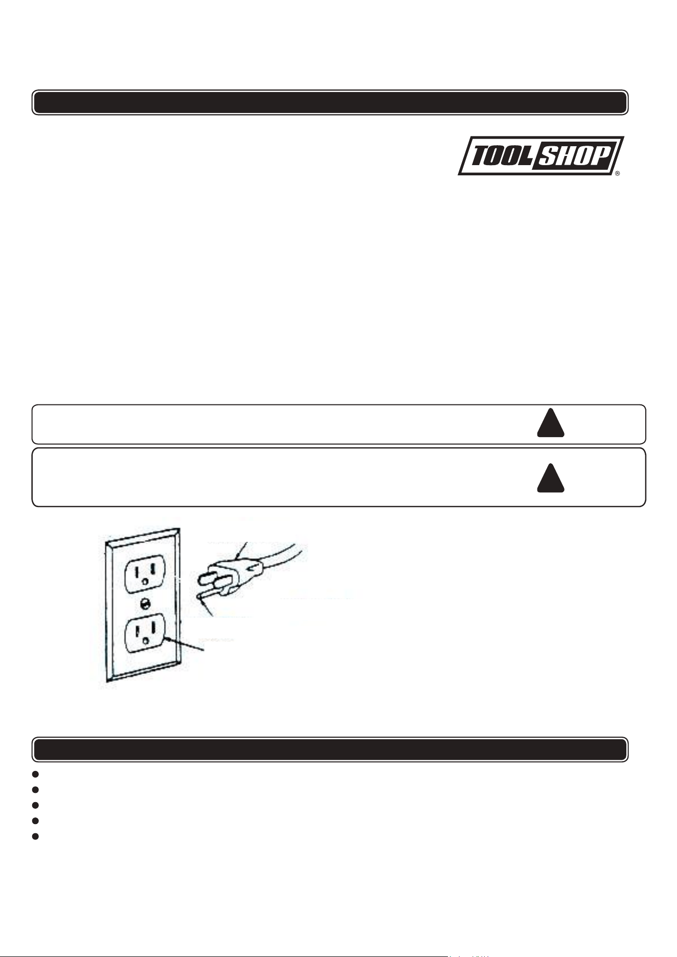
FIGURE 1
GROUNDING PRONG
PROPERLY GROUNDED THREE
PRONG OUTLET
THREE PRONG PLUG
This tool is intended to use on a circuit that has an outlet that looks like the one in
Figure 1.
120V ~ 60Hz
2.1 AMP motor, 3,560 RPM (No-load speed)
Adjustable eye shields, spark guards & tool rests
Cast lron base with mounting holes
Two 6" grinding wheels included
(36 grit coarse & 80 grit medium)
SPECIFICATIONS
4
FUNCTION DESCRIPTION
1
12
13
4
4
5
6
7
8
8
7
5
2
6
5
3
3
2
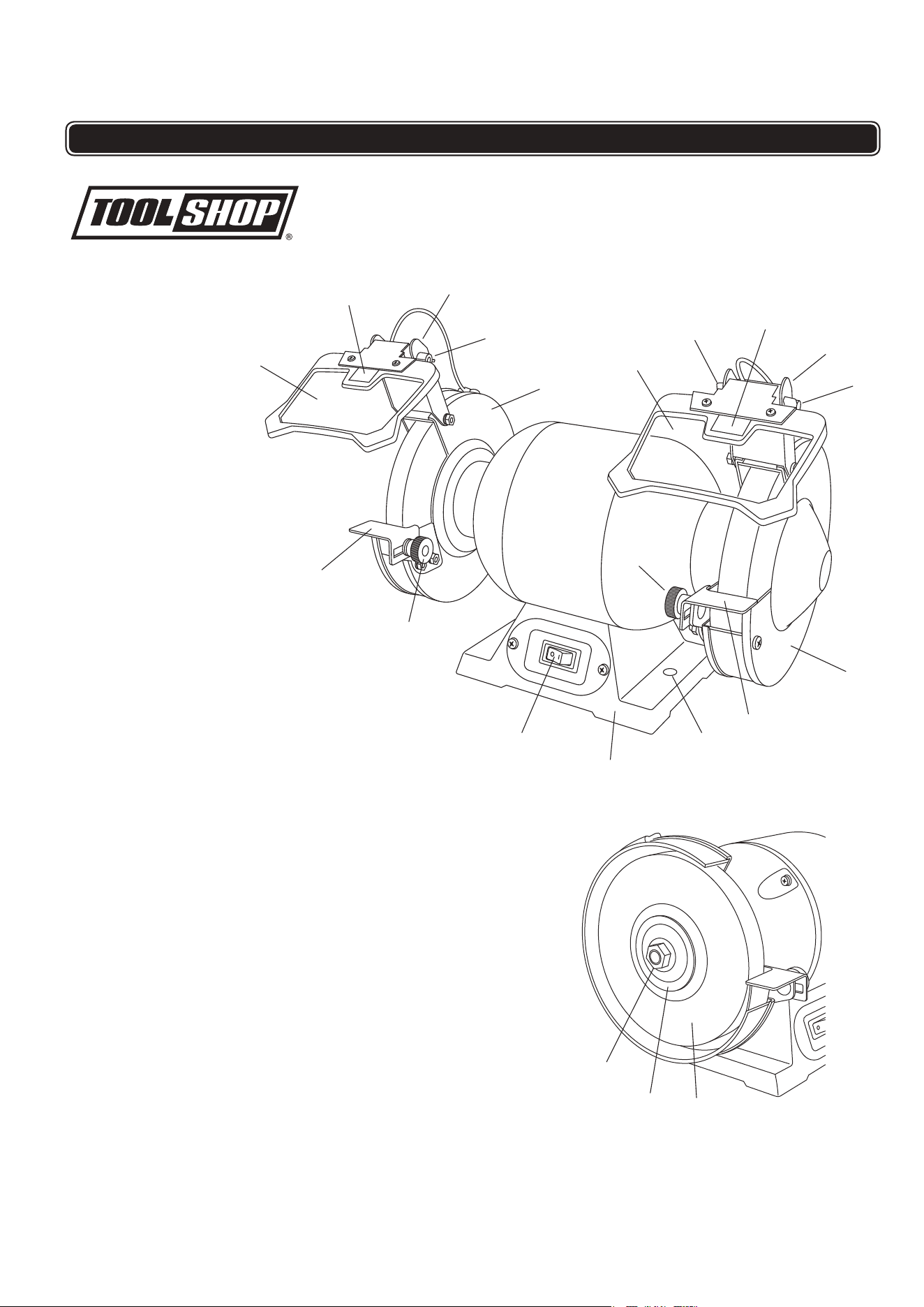
1. On/off switch
2. Tool rest
3. Tool rest locking knob
4. Eye shield
5. Eye shield locking knob
6. Spark guard
7. LED work light
8. Wheel guard
9. Grinding wheel
10. Grinding wheel locking nut
11. Outer grinding wheel flange
12. Base
13. Mounting holes
9
10
11
Fitting and adjusting the spark deflectors and eye shields
IMPORTANT: Prior to fitting the eye shields and spark deflectors, ensure the
grinder is turned off and the power plug is removed from the socket.
Note: Always check to ensure the eye shields are correctly fitted and the
eye shield spark deflectors are correctly adjusted each time the grinder is
used. Eye shields and spark deflectors must be fitted over each grinding
wheel.
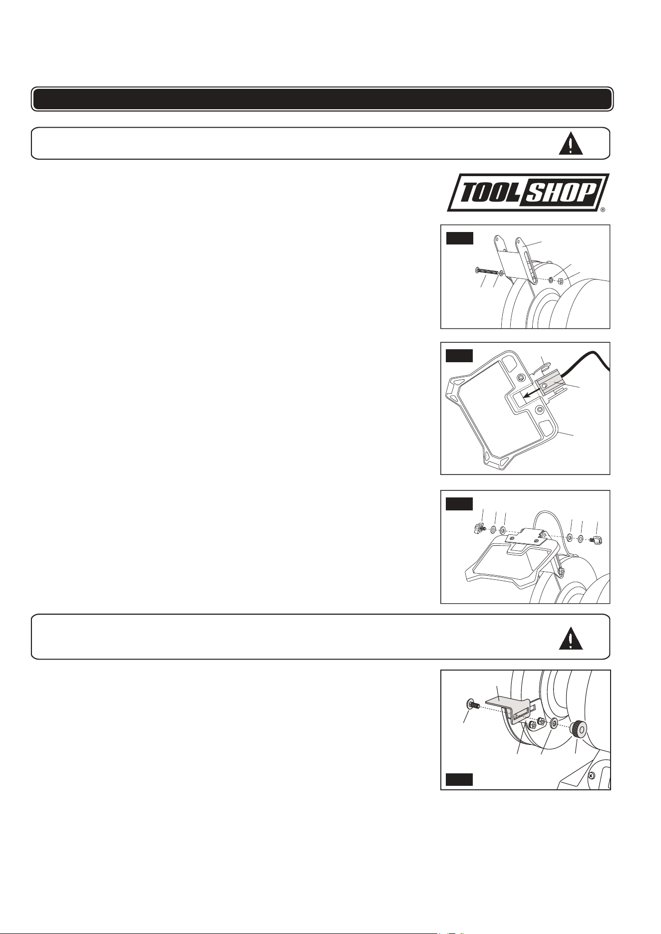
1. Remove the bolt (1,2,3,4) from the top of the wheel guard shown in figure 2.
2. Position the spark
guard (5) to the top of the wheel guard as shown in figure 2.
3. Reinsert the bolt (1) and the washer (2) through the spark guard(5) and wheel
guard, followed by, lock washer (3), and nut (4).
4. Tighten to secure the spark guard(5) onto the wheel guard.
5. Hold the eye shield (6) upside down and insert the light assembly (7), by
sliding it into position between the shield and the shield’s support bracket (8),
as shown in figure 3.
6. Position the eye shield on the spark guard(5) as shown in figure 4.
7. Place a lock washer (9) and a flat washer (10) to each eye shield locking
knobs (11), then insert through the spark guard(5) and thread into the
eye shield, tighten the knob in a clockwise direction to secure the eye shield
onto the spark guard(5).
8. Rotate the wheel by hand one full revolution to ensure the wheel can rotate
without contacting the spark guard(5). Firmly tighten the knob retaining
the spark guard(5).
9. Repeat for the opposite side.
Fitting the tool rests
The tool rests are required for each high speed grinding wheel to assist in
the grinding operation.
Note. The tool rests are right and left handed. Follow the diagrams to ensure
the correct tool rest is fitted to the correct side.
IMPORTANT. Prior to fitting the tool rests, ensure the grinder is turned off
and the power plug is removed from the socket.
1. Hold the tool rest (1) in the correct position against the tool rest bracket (2).
5
ASSEMBLY AND ADJUSTMENTS
5
4
3
2
1
7
6
8
9
11
11
9
10
10
WARNING:
To reduce the risk of injury, never connect plug to power source
outlet until all assembly steps are completed.
WARNING:
To reduce the risk of injury, never use a bench grinder on which the
tool rest has not been fitted or where the tool rest has not been
correctly adjusted.
FIG. 2
FIG. 3
FIG. 4
3
2
4
5
1
FIG. 5
6
ASSEMBLY AND ADJUSTMENTS
2. Insert bolt (3) through tool rest bracket and toolrest, followed by a washer (4)
and locking knob (5).
3. Tighten the locking knob sufficiently to support the tool rest but still allowing the
tool rest to slide inwards and outwards.
4. Slide the tool rest to within a maximum of 1.5mm from the wheel. Rotate the
wheel one full revolution by hand to ensure the wheel does not contact the tool
rest.
5. Tighten the locking knob firmly to retain the assembly.
6. Repeat the assembly operation for the second tool rest.
Mounting Bench Grinder to Workbench
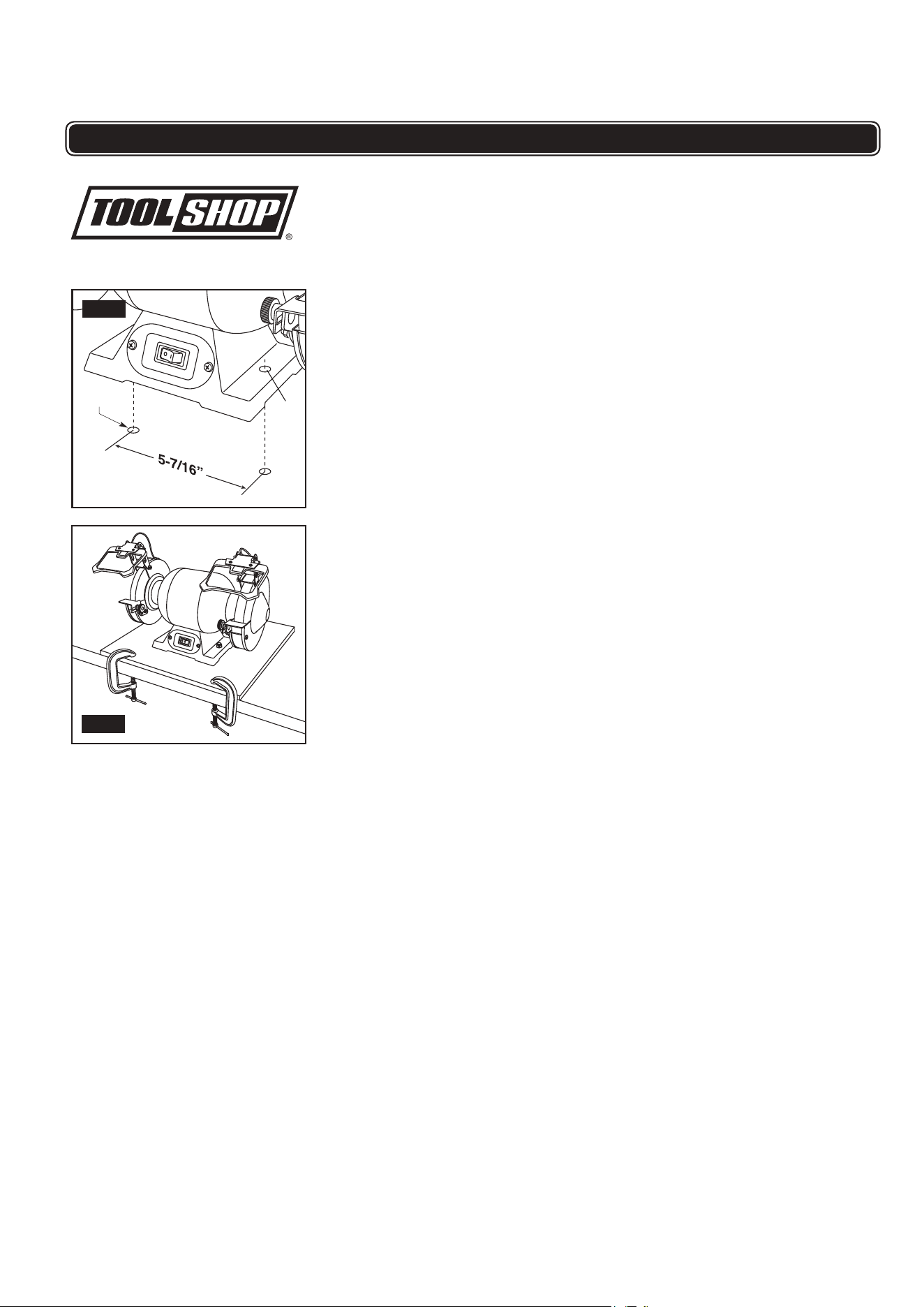
If bench grinder is to be used in a permanent location, it should be fastened
securely to a firm supporting surface such as a stand or workbench using the
two mounting holes (1), one of which is shown in figure 6.
When mounting grinder to a workbench, holes should be drilled through the
supporting surface of the workbench using the dimensions illustrated (Fig. 6).
1. Each of the two mounting holes should be bolted securely using 5/16" hex nuts
(not included). Screw lengths should be 1-1/2" longer than the thickness of the
bench top.
2. Locate and mark where the grinder is to be mounted.
3. Drill two (2) 7/16" diameter holes through workbench.
4. Place bench grinder on workbench aligning holes in base with holes drilled in
workbench.
5. Insert two (2) 5/16" screws and tighten.
Mounting to Plywood
An alternative method of securing your bench grinder is to fasten the grinder
base to a mounting board 12" x 18" minimum size to prevent grinder from
tipping while in use. Any good grade of plywood with a 3/4" minimum
thickness is recommended (Fig. 7).
1. Follow instructions for mounting to workbench, substituting a plywood board 12"
x 18" minimum size and using 5/16" flat head screws, lockwashers and hex nuts
(not included). Screw length must be at least 1-1/2" more than the thickness of
the mounting board.
NOTE: For proper stability, holes must be countersunk so screw heads are flush
with the bottom surface of the supporting board.
2. Securely clamp board to workbench using two or more “C” clamps (Fig. 7).
Supporting surface where grinder is to be mounted should be examined carefully
after mounting to insure that no movement can occur during use. If any tipping or
walking is noted, secure the workbench or stand before operating the bench grinder.
1
7/16”
FIG. 6
FIG. 7
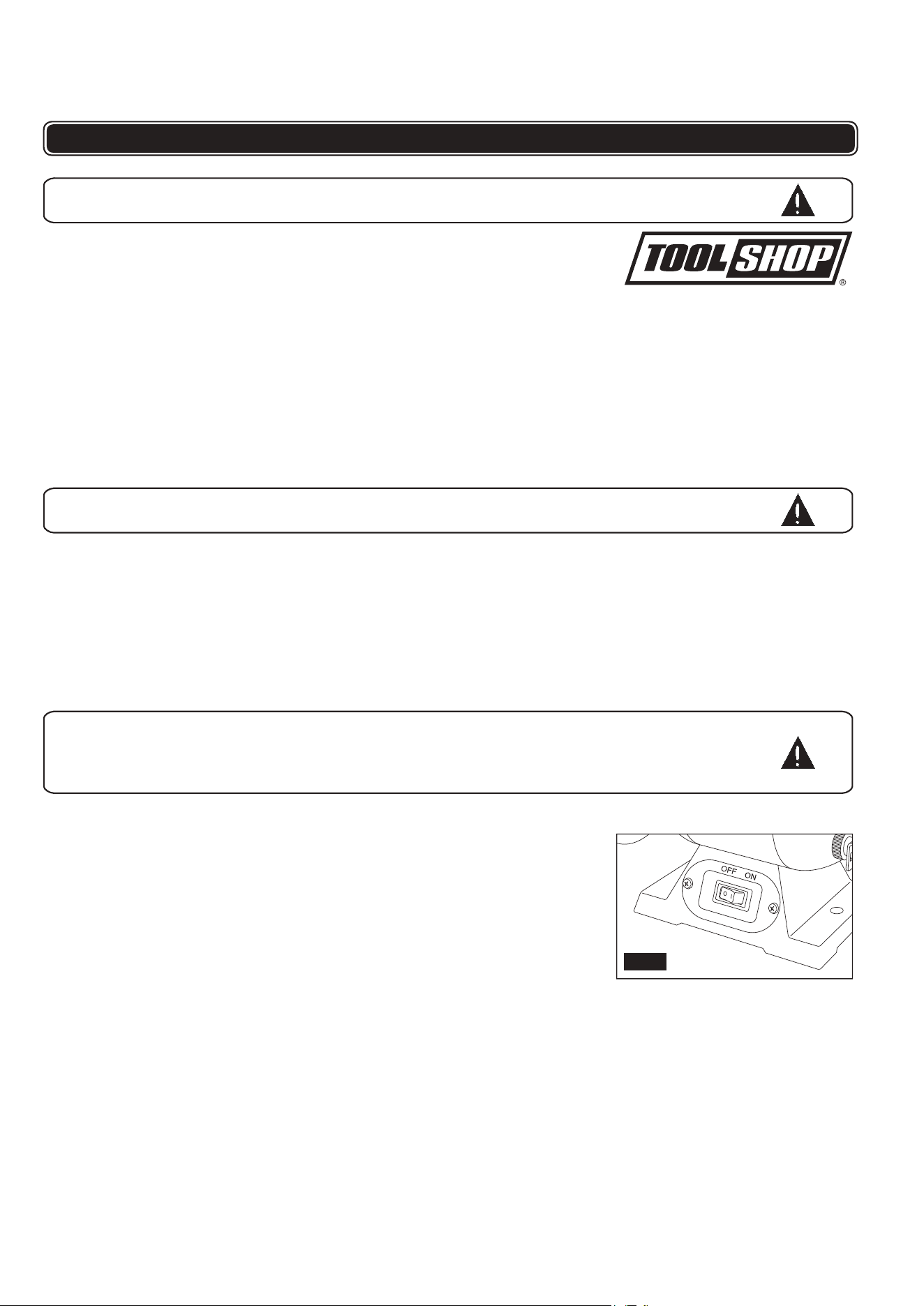
IMPORTANT: Prior to using the grinder, check that the eye shields, spark
guards, and tool rests are fitted and correctly adjusted and that you are
wearing safety gear including eye, hearing and breathing protection.
1. Turn the wheel by hand to make sure it does not touch the guard, eye shields,
spark guards or tool rests and runs freely.
2. Stand to one side, turn the switch on and allow the motor to reach full speed.
To start grinder: push the right hand side of the switch. To turn the grinder off,
push the left hand side of the switch. The “ON” and “OFF” positions are stamped on
the switch plate (Fig. 8). If the grinder does not immediately start, switch the grinder
“OFF”, disconnect the power cord and check voltage at power source.
3. Support the workpiece on the tool rest and gradually feed the workpiece onto the
wheel. Use pliers to hold small workpieces.
Note. Traverse the workpiece across the full width of the wheel to prolong its flat surface.
4. If the grinding operation causes the motor speed to noticeably decrease, pull back the
workpiece, allow the motor to regain full speed and restart the grinding operation, but
apply less force.
7
OPERATION
WARNING:
Risk of injury due to accidental starting. Do not use in an area where
children may be present.
WARNING:
To reduce the risk of injury, no adjustments to tool rests, spark shields or
other components should be made while the grinder wheels are turning.
LED Light
Your tool is equipped with LED lights for better visibility in the work area
during operation. When the tool is turned on, the light will turn on
automatically and stays on until the tool is turned off.
How to true and dress the wheels
Dressing a wheel cleans and levels the front surface to increase efficiency of
operation and prevent vibration.
1. Dressing a wheel involves the use of a wheel dresser which is not supplied with
the grinder. Follow the manufacturers instructions of the wheel dresser.
2. Adjust the tool rest to allow the front part of the wheel dresser to fit between the
tool rest and wheel.
3. Start the motor and move the dresser across the front of the wheel a sufficient
number of times until the surface is level. It is not necessary to apply excessive
force in an attempt to dress the wheel in one pass of the wheel dresser.
4. Adjust the tool rest so that it is no more than 1.5mm from the wheel.
5. Adjust the spark deflector to ensure the gap between the deflector and wheel is
ess than 6mm.
WARNING:
To reduce the risk of injury, only use the front face of the grinding
wheel, not the sides. Note that the workpiece can get very warm. It may
be necessary to cool a workpiece by dipping it in a coolant or in water.
Do not apply coolant or water to the grinding wheel.
FIG. 8

8
ASSEMBLY AND ADJUSTMENTS
MAINTAINING YOUR BENCH GRINDER
Grinder adjustments
During the life of the grinder some adjustments are required to maintain a safe
working environment.
Please ensure the following:
• Always adjust the eye shields to the most comfortable and most effective angle
to suit the task being performed.
• As the wheels wear, the spark guards must be adjusted to ensure the gap
between the spark guards and wheel does not exceed 6mm.
• As the wheels wear the tool rests must also be adjusted so there in never a gap
of greater than 1.5mm between the wheel and the edge of the tool rest.
Changing a grinding wheel
IMPORTANT: Prior to changing a wheel, ensure the grinder is turned off and
the power plug is removed from the socket. Make sure that the replacement
wheel is rated at 3500 RPM or higher.
1. Loosen and remove the 3 bolts (1) on the wheel guard (2), as shown in figure 9.
2. Remove the wheel guard.
3. To prevent wheel rotation, place a wood wedge (3) between the grinding wheel
and the tool rest (Figure 10).
4. Remove the locking nut (4) (see note below for correct direction of rotation),
outer flange (5) and the wheel (6).
Note: The wheel on the left-hand side of the bench grinder has a left-hand thread
and is unscrewed in a clockwise direction. The wheel on the right-hand side of the
bench grinder has a right-hand thread and is unscrewed in an counter-clockwise
direction.
5. Fit the replacement wheel (6) and outer flange (5) on the shaft ensuring that
there is a blotter between the wheel and the flanges on each side of the wheel.
Ensure the wheel is a slide fit (not loose) on the spindle (Figure 11).
6. Replace the grinding wheel nut (4) and tighten. (See the note above regarding
the direction of rotation of the nut).
7. Replace the wheel guard.
8. Reinsert the 3 bolts (1), washers, lock washers, nuts, and tighten wheel guard in
place.
9. Re-adjust the tool rest, spark deflector and eye shield.
10. Rotate the wheel by hand to check for free movement and proper adjustments.
11. Plug in the bench grinder, put on eye protection, stand to one side and run the
grinder at full speed for several minutes.
Maintenance
1
3
3
4
5
7
6
2
FIG. 9
FIG. 10
FIG. 11
WARNING:
To reduce the risk of injury, turn power switch “OFF” and remove
plug from the power source outlet before maintaining or lubricating
your grinder.
GENERAL
Frequently blow out any dust that may accumulate inside the motor.
An occasional coat of paste wax on the work table will allow the wood being
cut to glide smoothly across the work surface.
9
MAINTAINING YOUR BENCH GRINDER
PARTS LIST AND SCHEMATIC DRAWING
CAUTION:
Certain cleaning agents and solvents damage plastic parts. Including:
gasoline, carbon tetrachloride, chlorinated cleaning solvents,
ammonia and household detergents that contain ammonia. Avoiding
use of these and other types of cleaning agents minimizes the
probability of damage.
WARNING:
To avoid shock or fire hazard, if the power cord is worn, cut or damaged
in any way, have it replaced immediately.
WARNING:
All repairs, electrical or mechanical, should be attempted only by trained
repairmen. Use only Authorized replacement parts; any other may create
a hazard.
Lubrication
All of the BALL BEARINGS are packed with grease at the factory. They
require no further lubrication.
Accessories
Use only recommended accessories. Follow instructions that accompany
accessories. Use of improper accessories may cause hazards.
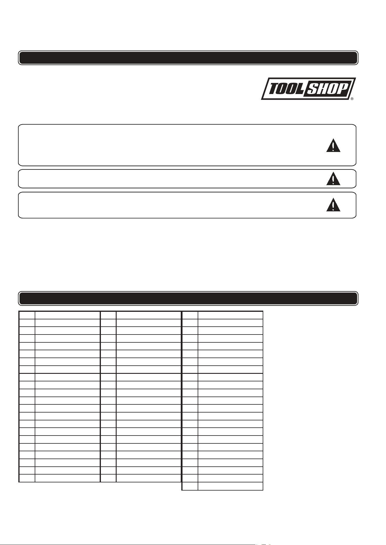
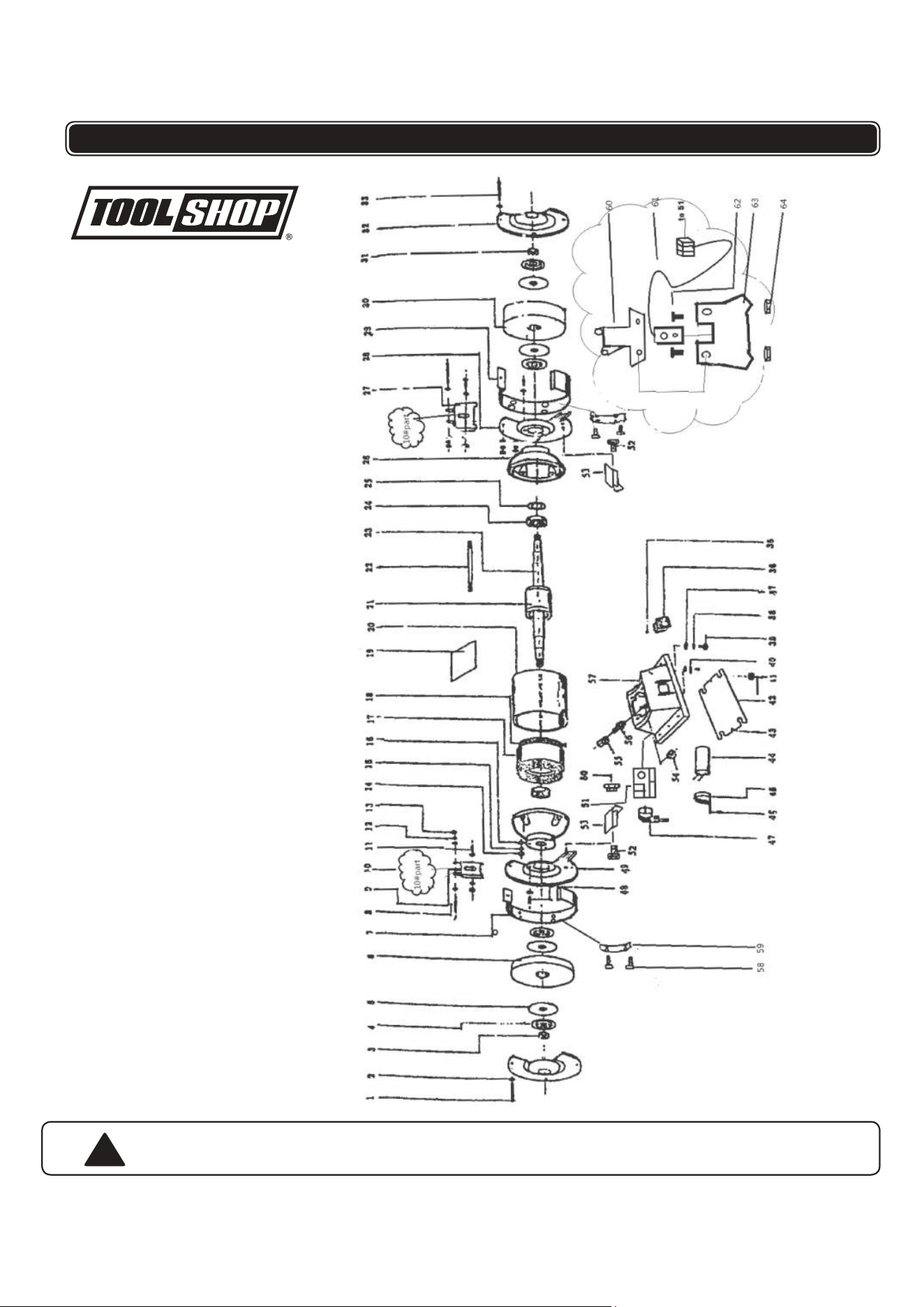
NO.
1
2
3
4
5
6
7
8
9
10
11
12
13
14
15
16
17
18
19
20
21
DESCRIPTION
Bolt
washer
wheel lock nut
wheel flang
nameplate of wheel
wheel
middle ring
bolt
eyeshild bracket
10#part
bolt
washer
screw
screw
washer
washer
stator
winding
label
stator housing
rotor
NO.
22
23
24
25
26
27
28
29
30
31
32
33
34
35
36
37
38
39
40
41
42
DESCRIPTION
bolt
axis
bearing
waved sping
end cover
eyeshild bracket
right inner cover
middle ring
wheel
screw
outer cover
bolt
right tool rest
bolt
switch
washer
washer
bolt
grounding plece
Rubbor foot
base plate
NO.
43
44
45
46
47
48
49
50
51
52
53
54
55
56
57
58
59
60
61
62
63
64
DESCRIPTION
bolt
capacitor
capacitor bracket
bolt
ping & cord
bolt
left outer cover
screw
circuit card
screw
left tool rest
screw
cable nut
cable adaptor
base
bolt
LED Light Cable Clips
eyeshield backet-2
LED linght
bolt
eyeshild
screw
10
PARTS LIST AND SCHEMATIC DRAWING
!
WARNING Repairs should be made by an authorized repair center. Do not
this power tool
. Contact at
for questions regarding this power tool.
1-866-915-8626
open or disassemble

TOOL SHOP®
1-YEAR LIMITED WARRANTY:
This
TOOL SHOP®
brand power tool carries a 1-Year Limited Warranty to the
original purchaser.
If the tool fails within one (1) year from the date of
purchase, simply bring this tool with your original sales receipt back to your
nearest
MENARDS
®
retail store. At its discretion,
TOOL SHOP®
agrees to
have the tool replaced with the same or similar
TOOL SHOP®
product free of
charge, within the stated warranty period, when returned by the original
purchaser with original sales receipt. Notwithstanding the foregoing, this
limited warranty does not cover any damage that has resulted from abuse or
misuse of the Merchandise. This warranty: (1) excludes expendable parts
including but not limited to blades, belts, bits, light bulbs, and/or batteries; (2)
shall be void if this tool is used for commercial and/or rental purposes; and (3)
does not cover any losses, injuries to persons/property or costs. This
warranty does give you specific legal rights and you may have other rights,
which vary from state to state. Be careful, tools are dangerous if improperly
used or maintained. Seller’s employees are not qualified to advise you on the
use of this Merchandise. Any oral representation(s) made will not be binding
on seller or its employees. The rights under this limited warranty are to the
original purchaser of the Merchandise and may not be transferred to any
subsequent owner. This limited warranty is in lieu of all warranties,
expressed or implied including warranties or merchantability and fitness for a
particular purpose. Seller shall not be liable for any special, incidental, or
consequential damages. The sole exclusive
remedy against the seller will be
for the replacement of any defects as provided herein, as long as the seller is
willing or able to replace this product or is willing to refund the purchase price
as provided above.
For insurance purposes, seller is not allowed to
demonstrate any of these power tools for you.
For questions / comments, technical assistance or repair parts –
Please call toll free at: 1-866-915-8626
(M-F 8am – 5pm EST)
SAVE YOUR RECEIPTS.
THIS WARRANTY IS VOID WITHOUT THEM.
6” BENCH GRINDER WARRANTY