REV250410
DUCTLESS MINI SPLIT SYSTEM AIR CONDITIONER / HEAT PUMP
WYT-25 Inverter Series
For 9,000-24,000 BTU/hr Systems
Quantum Hyperformance (R-454B) -
WT Indoor and YN Outdoor
Installation &
User Manual
IMPORTANT NOTICE:
Read this manual carefully before installing or
operating your new air conditioning system.
Be sure to save this manual for future
reference.
T
Troubleshooting..............................
51
A
Appendix..............................................
53
1.
Leak Check/Test Run.......
49
2.
2.
Electrical and Gas Leak Check................
49
54
Test Run..................................................................
50
Guidelines for Drilling the Wall Hole........................
3.
55
Simplified Wiring Diagram...............................................
4.
Control Board Wiring Diagrams..................................
56
5.
Additional Leakage Sensor Information................
57
6.
Disposal Guidelines...............................................................
58
7.
Notes from the Installer......................................................
59
1.
53
Anchoring the Outdoor Unit Guide
.........................
9
MC MC
1.
2.
Mounting Instructions...................................................................
40
3.
Outdoor Unit Installation Location Selection................
41
4.
5.
Connection of Refrigerant Piping..........................................
Electrical Wiring of the Outdoor Unit..................................
42
44
47
Evacuating the Refrigerant Circuit........................................
8
Outdoor Unit Installation...................
40
1
Air Conditioner Installation & User Manual
Table of Contents
5
1 Safety Precautions............................ 2
4
6
2 System Components........................
3
Included Accessories........................
4
Indoor Unit Overview.........................
20
5 Operating Instructions....................... 7
19
30
6 Maintenance....................................
7
A2L Refrigerant................................
8
Indoor Unit Installation......................
49
9 Outdoor Unit Installation................... 38
52
T
Troubleshooting...............................
A
Appendix..........................................
10
Electrical/Gas Leak Check & Test Run
.... 47
Page 5
6.
For all electrical work, follow all local and national wiring standards, regulations, and especially this
Installation Manual. You must use an independent circuit and a dedicated breaker to supply power.
Do not connect other appliances to the same circuit. Insufficient electrical capacity or defects in
electrical work can cause electrical shock or fire.
7.
9.
10.
11.
8.
CAUTION
For all electrical work, use the specified cables. Connect cables tightly, and clamp them securely to
prevent external forces from damaging the terminals. Improper electrical connections can overheat
and cause fire, and may also cause shock.
All wiring must be properly arranged to ensure that the control board cover can close properly.
If the control board cover is not closed properly, it can lead to corrosion and cause the connection
points on the terminal to heat up, catch fire, or cause electrical shock.
In certain functional environments, such as kitchens, server rooms, etc., the use of specially designed
air-conditioning units is highly recommended. This is intended as a general comfort cooling system.
If part of the electrical wiring is damaged, it must be replaced by a certified service agent or similarly
qualified technicians, in order to avoid a hazard.
This appliance can be used by children aged 8 years and above, as well as persons with reduced
physical, sensory, or mental capabilities, or lack of experience or knowledge, if they have been given
supervision or instruction concerning use of the appliance in a safe way, and understand the hazards
involved. Children shall not play with or near the appliance. Cleaning and user maintenance shall
not be done or attempted by children or untrained personnel without proper supervision.
Note about Fluorinated Gasses
1.
The product must be properly grounded at the time of installation, else electrical shock may occur.
2.
Install drainage piping according to the instructions in this manual. Improper drainage may cause
water damage to your home and property.
WARNING
For units that have an auxiliary electric heater, do not install the unit within 1 meter (3 feet) of
any combustible materials.
Do not install the unit in a location that may be exposed to combustible gas leaks. If combustible
gas accumulates around the unit, it may cause fire.
Do not operate your air conditioner in a highly humid space, such as bathrooms or laundry rooms.
Exposure to high humidity or water can cause electrical components to short circuit.
1.
This air-conditioning unit contains fluorinated gasses. For specific information on the type of gas
and the amount, please refer to the relevant label on the unit itself.
2.
Installation, service, maintenance, and repair of this unit must be performed by qualifed and
well-trained personnel.
3.
Product removal and recycling must be performed by a certified HVAC technician.
4.
If the system has a leak-detection feature installed, it must be checked for its functionality at least
every 12 months.
5.
When the unit is being checked for leaks, proper logging and record-keeping of all checks is
strongly recommended.
2
Air Conditioner Installation & User Manual
Warning
Caution
Danger
Warning
Do not power the system using an extension cable or with wiring smaller than the specified gauge. Do not
share the electrical cable with other appliances. Improper or insufficient power supply can cause
undesirable operation, fire, or electrical shock.
When connecting the refrigerant piping, do not allow any substances or gases other than the specified
refrigerant to enter the unit. The presence of other gases or substances will lower the unit's capacity,
causing abnormally high pressure in the refrigeration cycle. This can cause an explosion or injury, as well
as permanent equipment failure. Note: No dust, humidity, or air is allowed to enter the unit.
Do not allow children to play with or around the air conditioner. Supervise children near the unit at all
times.
1. Trained personnel must complete the installation according to the applicable codes. Defective installation
can cause water leakage, electrical shock, or fire. Using the proper tools is required.
2. Perform the installation according to the instructions. Improper installation can cause water leakage,
undesirable performance, electrical shock, or fire. In North America, an authorized personnel must perform
the installation in accordance with the requirements of NEC and CEC.
3. If the unit requires repairs or maintenance, contact a qualified and licensed HVAC technician.
4. Only use the included accessories, parts, and specified items for installation. Using non-standard parts can
cause water leakage, electrical shock, fire, and total unit failure.
5. Install the unit on top of a firm structure that can fully support its weight. If the chosen location cannot
support the unit's weight or the installation is not done properly, the unit may fall and cause serious injury and
damage.
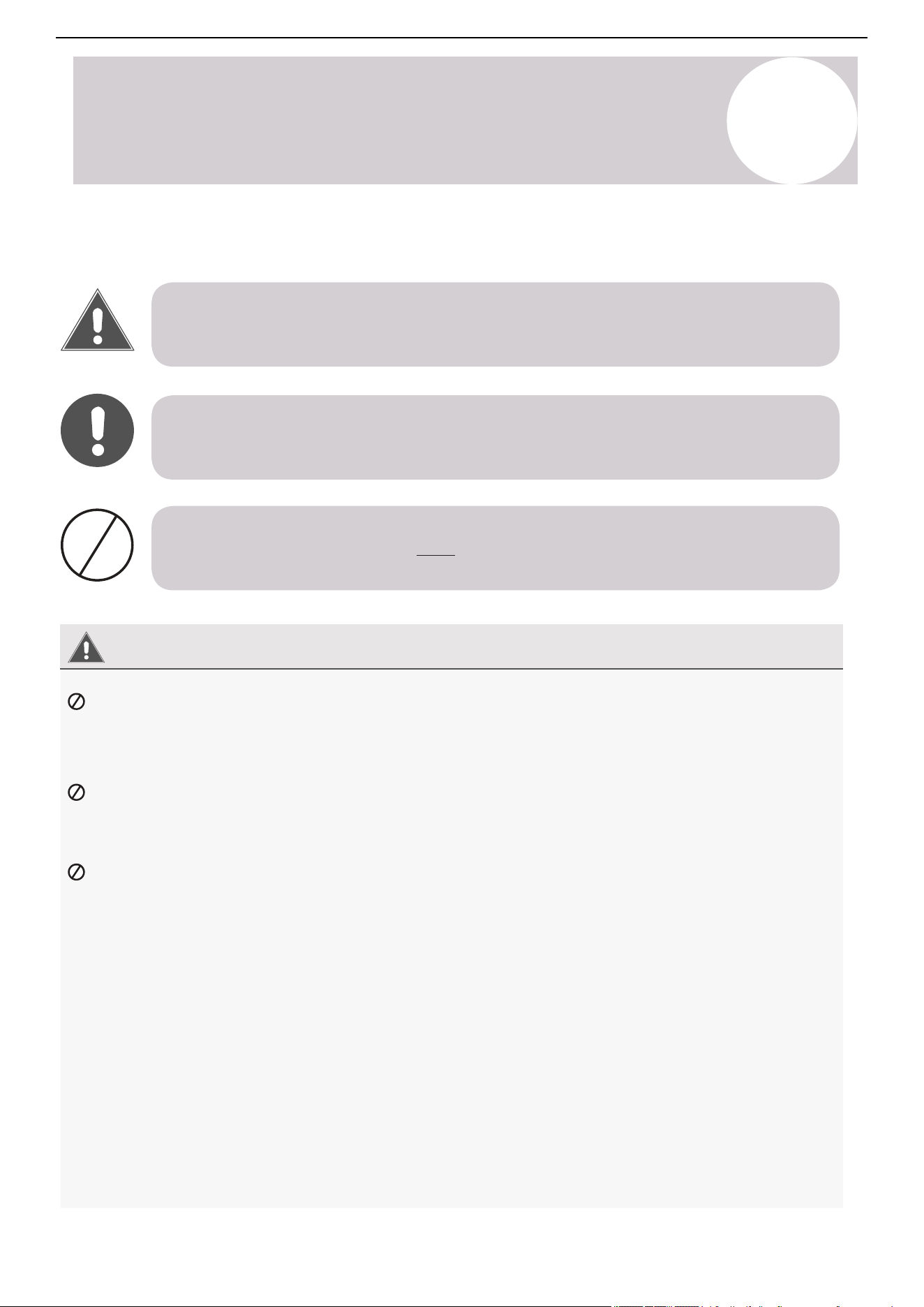
This symbol indicates that you must never perform the action shown.
This symbol indicates that ignoring the related instructions may cause moderate injury to
nearby individuals and/or damage to the appliance or other property.
This symbol indicates that ignoring the related instructions may cause death or serious injury.
Read and Understand All Safety Precautions Prior to Installation
Improper installation due to negligence of instructions may result in death, property damage, or serious injury.
The magnitude of the potential damage or injury is classified as either a Warning or Caution.
1
Safety Precautions
Page 4
This symbol indicates that ignoring the related instructions may cause death, or
serious injury.
This symbol indicates that ignoring the related instructions may cause moderate
injury to nearby persons, and/or damage to your appliance or other property.
WARNING
Safety Precautions
Read and Understand All Safety Precautions Prior to Installation
Improper installation due to negligence of instructions may result in death, property damage, or serious
injury. The magnitude of potential damages or injuries is classified as either a WARNING or a CAUTION.
CAUTION
DANGER
WARNING
Do not power the system using an extension cable or with wiring smaller than the specified gauge.
Do not share the electrical circuit with other appliances. Improper or insufficient power supply
can cause undesirable operation, fire, or electrical shock.
When connecting refrigerant piping, do not let any substances or gases other than the specified
refrigerant enter the unit. The presence of other gases or substances will lower the unit’s capacity,
and can cause abnormally high pressure in the refrigeration cycle. This can also cause explosion and
injury, as well as permament equipment failure. Remember: No dust, humidity or air is allowed to enter.
Do not allow children to play with or around the air conditioner. Children near the unit must be
supervised at all times.
This symbol indicates that you must never perform the action shown.
1.
Installation must be performed by trained personnel according to applicable codes. Defective
installation can cause water leakage, electrical shock, or fire. The usage of proper tools is required.
2.
Installation must be performed according to the installation instructions. Improper installation can
cause water leakage, undesired performance, electrical shock, or fire.
(In North America, installation must be performed in accordance with the requirements of NEC and
CEC, by authorized personnel.)
3.
Contact a qualified and licensed HVAC technician for any repairs or maintenance of this unit.
4.
Only use the included accessories, parts, and specified items for installation. Using non-standard
parts can cause water leakage, electrical shock, fire, and can cause total unit failure.
5.
Install the unit on top of a firm structure that can fully support its weight. If the chosen location
cannot support the unit’s weight, or the installation is not done properly, the unit may fall and
cause serious injury and damage.
3
Air Conditioner Installation & User Manual
Notes about Fluorinated Gases
1. This air conditioner contains fluorinated gases. For specific information on the type of gas and amount, refer to
the relevant label on the unit.
2. Qualified and well-trained personnel must complete the installation, repair the unit, and perform service and
maintenance.
3. A certified HVAC technician must remove and recycle the product.
4. If the system has a leak-detection feature installed, check its functionality at least every 12 months.
5. When checking the unit for leaks, it is recommended to properly log and record all checks.
Caution
For units with an auxiliary electric heater, do not install the unit within 3 feet (1 m) of any combustible materials.
Do not install the unit in a location that may be exposed to combustible gas leaks. If combustible gas
accumulates around the unit, it may cause a fire.
Do not operate the air conditioner in a highly humid space, such as bathrooms or laundry rooms. Exposure to
high humidity or water can cause electrical components to short circuit.
1. The product must be properly grounded during the duration of the installation process, otherwise electrical
shock may occur.
2. Install the drainage piping according to the instructions in this manual. Improper drainage may cause water
damage to your home and property.
6. For electrical work, follow all local and national wiring standards and regulations, especially in this installation
manual. You must use an independent circuit and dedicated breaker to supply power. Do not connect other
appliances to the same circuit. Insufficient electrical capacity or defects in electrical work can cause electrical
shock or fire.
7. For all electrical work, use the specified cables. Connect cables tightly, then clamp them securely to prevent
external forces from damaging the terminals. Improper electrical connections can overheat, causing fire and
electrical shock.
8. Properly arrange the wiring to ensure that the control board cover can close correctly. If the control board is not
closed properly, it can lead to corrosion and cause the connection points on the terminal to heat up, catch fire, or
cause electrical shock.
9. Use specially designed air conditioners for functional environments, such as kitchens, server rooms, etc.
10. If a part of the electrical wiring is damaged, a certified service agent or similarly qualified technicians must
replace the wiring in order to avoid a hazard.
11. Children aged 8 and above, as well as individuals with lack of experience or reduced physical, sensory, or
mental capabilities can use the appliance if supervision or instruction is given. Do not allow children to play with or
near the appliance. Children or untrained personnel should be restricted from cleaning and performing
maintenance on the appliance, unless they're given supervision.
Warning
1
Safety Precautions
2
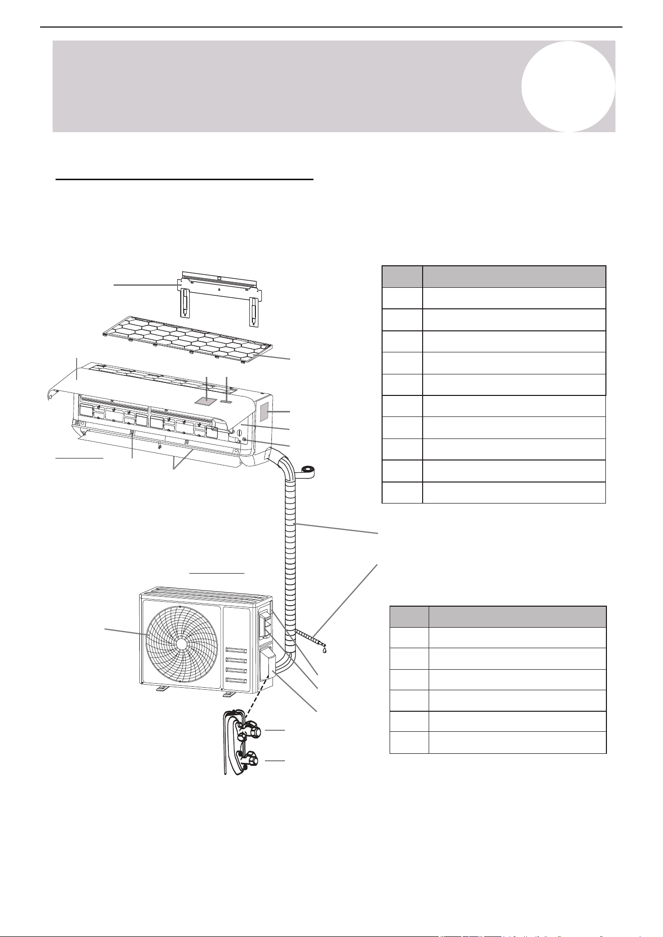
System Components
No.
Description
1
2
3
4
5
Wall mounting plate
LED display
Controller signal receiver
Front panel
Indoor unit rating label
6
7
8
9
10
Terminal block cover
Emergency (Manual) button
Air deflector & flap
Air outlet
Air filter
With the protective
cover removed
Indoor Unit
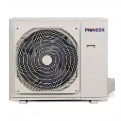
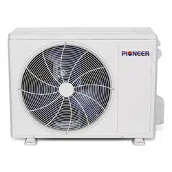
Outdoor Unit
9
10
15
16
4 5
7
8
11
3
1
14
13
12
2
6
High Wall-Mounted Air Conditioner
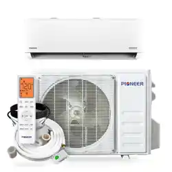
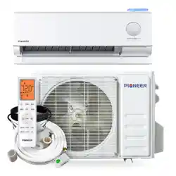
The system is made up of two units connected together via insulated copper pipes and an electrical
communication cable. Mount the indoor unit onto one of the walls in the room intended to be air conditioned.
Install the outdoor unit either on the ground outside or on the wall of the dwelling using suitable mounting
brackets.
Refrigerant piping
Condensate drain
No.
Description
11
12
13
15
16
Air outlet grille
Outdoor unit nameplate
Terminal block cover
Gas (Suction) line valve
14
Valve protection cover
Liquid line valve
Note: Serial numbers are typically located behind the
electronic control box cover cap of either unit.
Note: The illustrations are a simplified diagram of the appliance and may not fully reflect the system's actual
appearance. Technical data is printed on the system's labels.
4
Air Conditioner Installation & User Manual
Page 6
1
System Components
High Wall-Mounted Air Conditioner:
Note: The illustrations above are only intended to be a simple diagram of the appliance, and may not fully
correspond to the actual appearance of the system. Technical data is printed on the system’s labels.
The system is made up of two units connected together via insulated copper pipes and an
electrical communication cable. The indoor unit is mounted onto one of the walls in the room
that is to be conditioned. The outdoor unit is installed on the ground outside or on the wall
of the dwelling using suitable mounting brackets.
Owner’s
Manual
No.
Description
1
2
3
4
5
Wall Mounting Plate
LED Display
Controller Signal Receiver
Front Panel
Indoor Unit Rating Label
6
7
8
9
10
Terminal Block Cover
Emergency (Manual) Button
Air Deflector and Flap
Air Outlet
Air Filter
No.
Description
11
12
13
15
16
Air Outlet Grille
Outdoor Unit Nameplate
Terminal Block Cover
Gas (Suction) Line Valve
14
Valve Protection Cover
Liquid Line Valve
Note: Serial Numbers are typically located behind the
electronic control box cover cap of either unit.
With the protective
cover removed
INDOOR UNIT
OUTDOOR UNIT
9
10
15
16
4 5
7
8
11
3
1
14
13
12
Refrigerant Piping
2
Condensate Drain
6
3
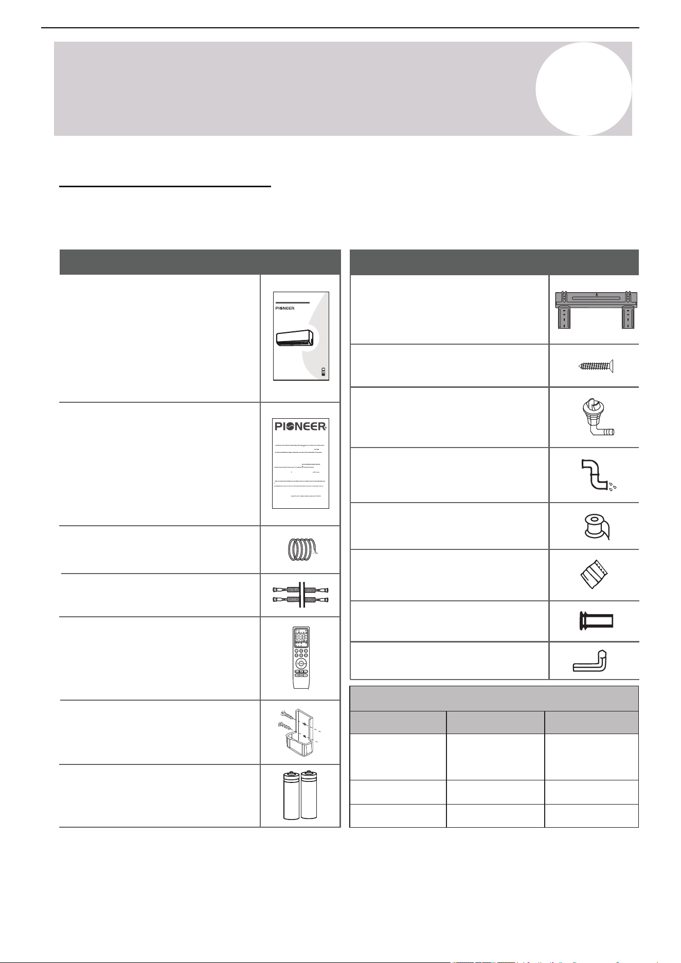
Included Accessories
1x Communication/Signal cable*
CS78421-548-754
SPLIT-TYPE ROOM AIR CONDITIONER
IMPORTANT NOTE:
e to save this manual for
our new air cor operating y
Read this manual carefully befor
onditioning
e installing
Installation and
Owner’s Manual
future
unit. Make su
referenc
r
e.
Name
Appearance
1x Insulated copper pipe*
1x
Indoor unit mounting plate
(Pre-attached to air handler
rear)
1x Condensate drain hose*
Name
Appearance
Connecting Pipe Diameters
18000
24000
BTU Capacity
Liquid Line
Gas Line
t
1.
o t
Unless this high quality product is registered properly as soon as it is put in service, all references made in this document to the term “warranty” solely refer
t
2
h
.
is
War
docu
ranty
me
is
nt
p
t
r
o t
ovi
h
d
e
e
t
d
e
r
by
m
P
“w
rk
ar
e
r
r
an
D
t
a
y
vi
” r
s
e
H
fe
V
r
A
t
C
o t
In
h
t
e
er
St
n
an
ation
dar
a
d
l,
W
nc
ar
.
r
(
a
h
n
e
t
r
y
e
, a
in
ls
aft
o a
er
s
r
f
e
ur
fe
t
r
h
e
er
d t
de
o
s
e
PD
d be
), th
low
ue s
.
follo
pplier of P
win
g
io
details:
neer® branded Split System Heat
u
Types of
mp Produ
In
c
st
ts (
alla
h
t
ere
ion
in
s: W
afte
ar
r
a
r
i
r
str
an
efer
y
re d to as
es t
Pr
o all
oducts
Produ
), c
cts,
ove
i
ri
nstal
n
I
g all part
led in
a r
s of
es
t
ide
he
n
P
c
r
e
odu
. Warr
r
cts
an
, s
a
ubje
ty als
c
o appli
t to the
s to P
roducts clas
c
i. Ar
ii. Are operated in unoccupied struct
a
ures or used for
iii. Are residential Products, but installed or used for c
pur
omme
pos
r
e
ci
s ot
al pu
he
r
r th
pos
an
es
comf
.
ort cooling / heating.
iv. Has been removed from the place it was originally installed and reinstal
d. Warranty Coverage: The warranty covers the parts of the Products, whic
le
h ma
d at
y
an
bec
oth
ome
er plac
defe
e
c
.
c
P
a.
omme
f
b
or
. Pr
r
oduct R
cial Pr
eg
odu
istra
c
tion
ts, i
:
n
R
st
eg
alled i
a
t
n
ti
c
on is
appli
omme
not
rci
requ ed f
r
or
tie
t
s
h
.
e availability of the Basic Warranty. Warranty registration is strongly urged and requ
ired
r
on
on
ion car
r
packed with the Product and send it in as instructed in the form OR conveniently register online at www.pdhvac.com and use the
.
eg
eg
Ex
is
ist
t
clu
ra
rat
s
t
i
i
s
li
t
n
o
k
d
.
W
e installed out
a
s
r
i
r
de
an
t
t
h
y
e
Co
Un
ve
it
r
e
ag
d S
e:
t
W
te
ar
s
r
of
ant
Ame
y doe
ri
s
ca.
not apply to any Product that:
tive due to the quality of the materials or
e
w
.
or
W
k
i. Damage
arr
man
anty D
ip,
r
oe
u
s
n
n
de
ot
r n
Co
or
ver:
mal u
P
D
s
i
e
s
an
not
d pr
resp
ope
on
r
si
mai
b
t
or
enash
s or
le
n
f
y inst
an
nc
y
allation
e
w
.
arr
or
ant
wr
y clai
ong
m
appli
due t
ca
o:
ti
. Warranty End Date: Products that have not been registered as instructed above are covered Warr
l
s
exc
t
e
or
e
igi
d a da
nal o
te, f
wn
ur
e
t
r
h
of
er
t
t
h
h
e
an
P
6 mo
roduc
n
t,
th
w
s
h
f
er
ollo
e it
wi
is
n
or
g t
ig
h
i
e
n
man
ally i
u
n
f
st
ac
al
t
le
ur
d
i
,
ng
an
da
d i
t
s
e
n
of
ot
t
t
h
r
e
an
P
s
r
f
oduc
e rable
t as
to th
code
e s
d i
u
n
bs
t
e
h
q
e
u
s
e
e
n
r
t
a
o
l n
wn
umbe
ers.
r. Warranty is provided only to t
he
ii. Damages or repairs arising fr
epairs arising as a r
om any ex
esult of a fault
ternal perils, out of PD’s control, such as
on.
iii. Damages or repairs arising f
rom use of non-compatible parts, alterations, modi
pipes, electrical surges, input power
with under or overvoltage, lightening or existe
nc
t
e
ion
of
s
c
or
or
i
ros
mpr
ive s
ope
u
r
bst
appli
ance
ca
s
ti
ne
on
ar
s.
by.
exchangers, fans and
v
blo
. Da
wer
mag
s, an
es or
y n
r
e
e
ce
pai
ss
r
ar
s n
y lu
ee
br
de
ica
d be
tion
cau
of
s
i
e
nt
of
er
u
n
si
al c
ng par
ompon
ts, s
e
u
nts
ppli
an
es or
d mai
ot
n
h
t
e
e
r
nan
add-
ce
on
of
c
exte
ompon
rnal
en
ac
t
c
s
e
t
s
h
s
a
or
t
i
ar
es
e
.
PD.
not supplied by or approved for use b
y
vi. Da
vii. Chan
mag
ge
e
s
s
t
or
ha
r
t
e
can
pairs
be
as
c
a r
on
e
si
su
de
lt
re
of
d c
i
os
mpr
me
ope
tic
r
,
u
n
s
ot
e, poor
ec
mai
ting t
nte
e
n
sy
an
st
c
e
e,
ms
wr
pe
on
r
g
for
ope
man
rat
c
i
e
on
, in
or
clu
i
mpr
ding
ope
bu
r
t
s
n
er
ot
vi
li
ce
mi
.
viii. Resetting of power or the circuit breakers and eplacement of other types of fuses, both internal and ext
t
e
e
r
d t
nal.
ix. Any damages of repairs caused by the use of dir
r
ty, recycle
h
d, wrong type or unapproved refrigerants and lubrica
r
t
h
s.
andling of system parts
xi.
Damages
or repairs caused by con
an
x. Damages or repairs due to moisture, air, dust, sand, dirt, etc., that have been allowed into the system by imprope
n
d components during installation.
t
tinuing use the Product, after a malfunction has been noticed or indicated at the display module,
f.
bu
xii. Damag
hrough an
e
e
s or
rror
pe
code
rfor
.
man
Warranty Begin Date: War
c
r
e
an
is
t
su
y be
es du
gins
e t
on
o i
e da
ope
te
r
of
ma
in
t
st
chi
al
ng
lat
,
i
P
on
roduc
and c
t se
ommi
lecti
s
o
si
n,
on
u
i
n
ng
de
of
r-s
t
i
h
zi
e
n
P
g
r
, o
odu
ver
c
-
t
s
,
i
i
zi
n
n
e
g
xi
, i
sti
mpr
ng r
ope
esi
r i
de
n
n
st
c
t
e
al
s
la
an
ion
d c
or
omme
misu
r
s
ci
e.
a
LIMITED PARTS WARRANTY
Pioneer® Brand Split System Heat Pump Products
© 2025, PARKER DAVIS HVAC INTERNATIONAL INC.
f
g
or a period of up to one year. Products that have been properly registered as instructed above will be
under the Basic
covered under
ant
S
y. T
tandard
he Basic
Warr
W
ant
arrant
y. The
y lasts
h
an
. R
d r
e
e
mai
side
ni
i
n
n
g
t
W
he
arr
dw
an
e
t
lli
y:
n
A
g
n
, or
y par
ope
t, c
rate t
ompon
he
bu
en
si
t or
ne
P
s
r
s in
odu
th
c
e
t
pr
hat
ope
w
r
as
ty
r
, i
e
n
pl
wh
ace
ich
d u
t
n
he
de
P
r
r
th
odu
e t
c
e
t
r
h
ms
ad be
of th
e
e
n
w
ori
ar
g
r
i
a
n
n
al
ty
ly i
w
nst
ll be
alle
c
d
o
.
v
war
er
gin date
ed under the
.
same
i. War
ra
rant
nty an
y P
d on
roce
ly f
dur
or
e:
t
P
he
D
dur
will fu
ation
rnish a ne
in which
w or
th
re
e ori
manuf
ginal
t
w
acture
arran
d r
t
e
y
pla
for
ce
the
me
P
n
rodu
t par
ct
t
d
,
is
wit
appli
hout
cable
an
y
, as c
char
omme
ge for t
n
he par
ced on
t it
i
it
s
s
e
be
lf, for the re
par
pla
d us
cement of an
e and
y
ermined to have failed discretion, due to efec orkmansh
proper maint
t that has been det
enance. Associated shipping costs for the
, by PD at its sole
replacement parts may also be covere
ts in its materials or w
d at PD’s expense, at its own disc
ip under standar
retion and under
certain conditions, while the shipping method used will be solely determined by PD. Otherwise, the payment of the shipping costs for the part will be
the sole responsibilit of the owner of the Product. PD reserves the right to ask the owner of the Product to return the failed part to PD, before
j. La
e
cement of th
t
p
, ma
n
ls
y
tor after a r laceme part may be sent out.
re
ar
ar
g
e
sponsibili
s
v
y of the
mo
he
. No oth
t
c
h
t
osts
re
p
pl
la
bor cos
nt,
t
t
e
al
r
i
e d
la
a
ti
ef
on
an
ec
,
t
r
iv
e
d ot
mo
e par
her
v
t,
cos
re
ts
mai
:
ppi
A
n
n t
n
y
g
l
,
he
e
r
t
abor
e
c.,
, involved in diagnosis, lodging, transportation, se
rvicing, repair,
k
ac
efri
e
ge
ed u
me
rant:
i
A
ns
ny costs relat arging, re i
t
ng
o be
t
er
me
e
d u
n
o
t,
n
wne
or
de
r
r
e
r t
v
w
al
arr
of
er
an
e
y
r
.
co
an
. R
v
ed t
al
.
,
o ch
shi
All P
ch
ts go through vigorous quality controls at vari
efrigerant,
ous statio
and t
ns and leav
he cost of the r
e the fact
efrig
ory in pe
erant itself
rfect
, ar
wor
e not
k
ing
d
er
does not co
sealed
v
nder an
er an
condition
y
y cir
. P
claims
rod
r
u
cumstances
c
elated t
ts are i
o th
r
ndividually
oduc
e lack of r
t
efrige
ested in high
rant in n
ly sen
ew Pr
sitiv
oduc
e heli
ts, discov
um vacuum c
ered upo
hamber
n arrival
s for
, or durin
existence of r
g installat
efrigeran
ion, as w
t leaks. Ther
ell as subsequent
efore PD
refrigerant losses occurring at any time afterward
Note: Items with an asterisk * may be sold separately and are sometimes supplied by the installer. Therefore,
some items may differ in appearance, shape, or length, depending on the particular installation.
1x
Installation & User manual
1x
Warranty card
1x
Remote controller
1x
Remote controller holder
2x
Remote controller batteries
1x Set of mounting plate screws
Plastic drain joint plug for
the outdoor unit
(Use only for wall-mounted
condensers)
1x
1x
Wrapping tape*
1x
Wall-hole packing sealant*
1x
Wall sleeve*
1x
Allen wrench for
opening service valves
9000 - 12000
5
Air Conditioner Installation & User Manual
¼”⅜”
½”
⅝”
¼”
¼”
Accessories & Components
The air conditioning system comes with the following accessories. The asterisk items are sold separately. Use
all of the installation parts and accessories to install the air conditioner. Improper installation may cause the
equipment to fail, or result in water leakage, electrical shock, or fire.eq
4
Indoor Unit Overview
2
3
1
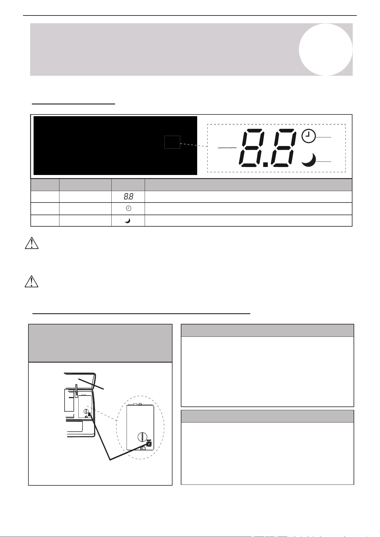
No.
Description
Symbol
LED Icon
1
2
3
Sleep
Timer
Temp. Display
Indicates that the system is currently in Sleep mode
Indicates that the Timer function has been set
Displays the current set temperature or any error codes
Front Panel Display
6
Air Conditioner Installation & User Manual
Emergency
button
Front panel
Emergency Manual Button & Auto-Restart Function
Emergency Manual Button
If the remote controller fails to operate the system, follow these steps:
1. Open and lift the front panel up at angle to gain access to the
emergency button.
2. Press the manual button once to start the unit in Cooling mode.
3. Press the button again within 3 seconds to start the unit in Heating
mode.
4. Press the button a 3rd time within 5 seconds to turn off the unit.
Auto-Restart Feature
The emergency button is located on the terminal
block cover of the unit under the front panel.
The shape and positions of the switches and indicators may vary according to the model, however the
functions remain the same. There may be variances between the amount of digits that are shown on the
remote controller (3) vs. the amount on the indoor unit (2).
It is important not to obstruct the front panel, otherwise it may not be able to receive infrared commands
from the remote controller. In addition, ensure that the panel is not covered with paint or adhesive layers, as
well as no nearby signal emitting devices.
This appliance is programmed with an Auto-Restart function.
In case of sudden power failure, the control module will remember the
settings configured before power loss.
When power is restored, the unit will restart automatically and be set to
the previous settings, which were preserved with this memory function.
Page 8
Indoor Unit Overview
3
2
3
1
No.
Description
SymbolLED Icon
1
2
3
SLEEP
TIMER
Temp. Display
Indicates that the system is currently in SLEEP mode
Indicates that the TIMER function has been set
Displays the current set temperature or any error codes
Front Panel Display
The shape and position of switches and indicators may vary according to the model, however the functions remain the same.
There may be variances between the amount of digits that are shown on the remote (3) vs. the amount on the indoor unit (2).
It is imperative that the front panel is not obstructed, otherwise it may not be able to receive infrared commands from the remote.
As such, ensure that the panel is not covered with paint or adhesive layers, and that there are no nearby signal emitting devices.
Emergency
Emergency Manual Button And Auto-Restart Function
Button
Front Panel
Emergency Manual Button
If the remote controller fails to operate the system, proceed as follows:
Auto-Restart Feature
• Open and lift the front panel up at an angle to gain access to the
emergency button.
• Press the manual button once to start the unit in COOL mode.
• Press the button again within 3 seconds to start the unit in HEAT mode.
• Press a 3rd time within 5 seconds to turn OFF the unit.
This appliance is programmed with an auto-restart function.
In case of sudden power failure, the control module will remember the
settings configured before power loss.
When power is restored, the unit will restart automatically, and will be
set to the previous settings, which were preserved with this memory
function.
The emergency button is located at
the terminal block cover of the unit
under the front panel.
Owner’s
Manual
5
Operating Instructions
The display and some features of the remote controller may
vary according to the model of the system.
The shape and positions of the buttons and indicators may
vary according to the model of the system, but the features
and functionality would remain the same.
The unit will confirm the successful reception of each button
command with a beep.
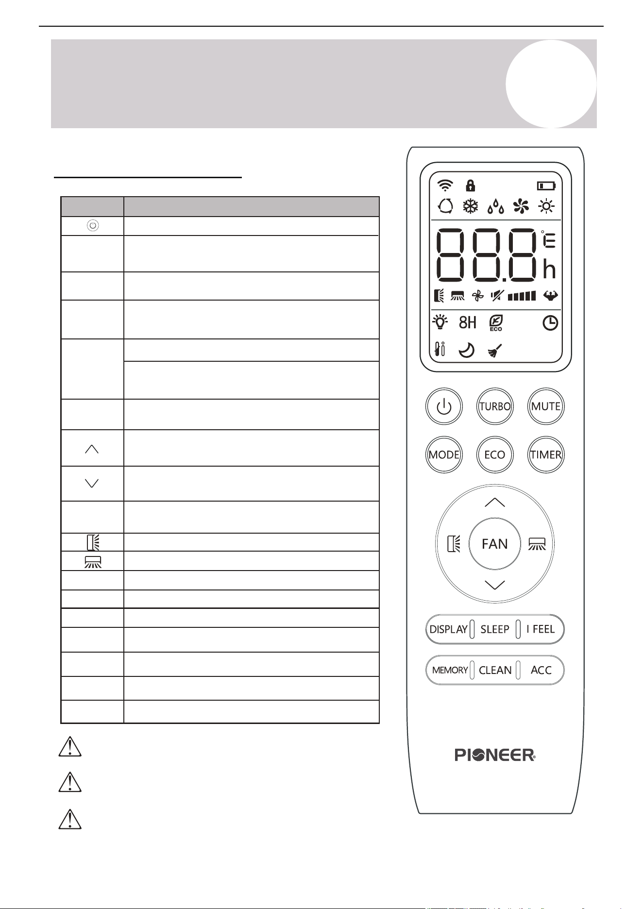
Remote Buttons Overview
7
Air Conditioner Installation & User Manual
Button Description
Turn the air conditioner on or off
Activate/deactivate the ECO feature
Configure the automatic on/off times
Toggle the system’s Sleep mode
Activate/deactivate the up-down louver motor
Turn the LED display on or off
Activate/deactivate the left-right louver motor
Put the system into Silent mode
Hold MODE+TIMER for child-lock
Activate/deactivate the system’s Follow Me mode
Increase set temperature and timing, as well as
navigate the functional menu
Decrease set temperature and timing, as well as
navigate the functional menu
Long press to activate the 46°F “Away
from Home” freeze protection setting
Configure the fan speed
(Auto, Low, Mid, and High)
MODE
Activate/deactivate the Turbo feature to allow the
system to rapidly reach set temperatures
DISPLAY
MUTE
[LOCK]
Activate/deactivate Self-Clean mode
CLEAN
Recall saved temperature/mode/fan settings
MEMORY
Reserved for future usage
ACC
I FEEL
TURBO
TIMER
FAN
SLEEP
ECO
Select the mode of operation
(Auto, Cool, Dry, Fan, and Heat modes)
Page 11
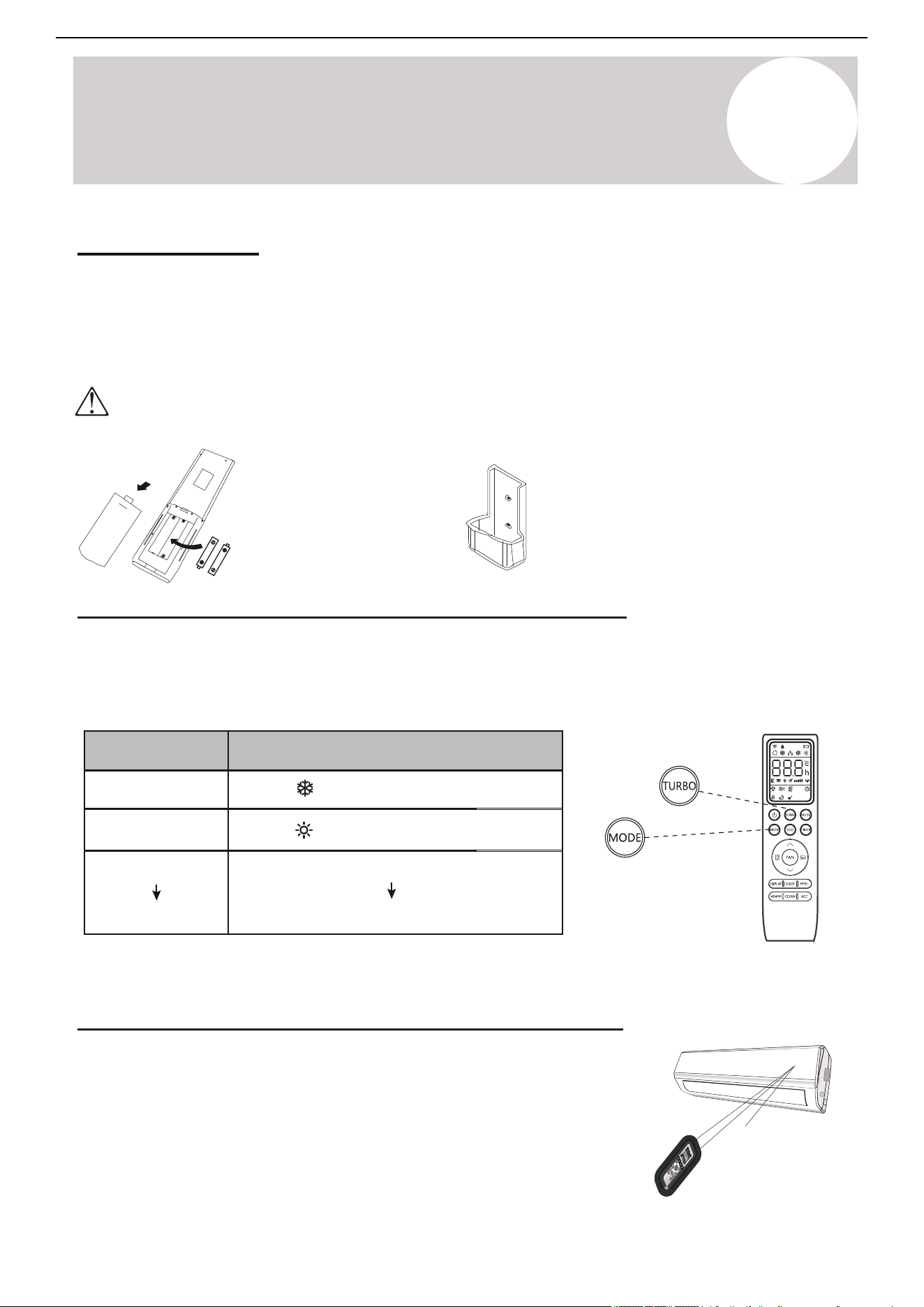
Configuring Remote Controller Settings (some models)
Depending on the system, the control type (Cooling Only or Heat Pump) and the unit of
Temperature (°C or °F) can be configured using the controller buttons. Operate as below.
All configuration must be done as soon as batteries are inserted into the remote.
Replacement of Batteries
Remove the battery cover from the rear of the remote controller, by sliding it downward in
the direction of the arrow as depicted below. Install batteries according to the depicted
directions (+ and -) as shown on the remote controlller. The cover then slides back into place.
Note
Please remove batteries to avoid
leakage damage when not
being used for a long time.
Note
The remote can be placed
inside the cradle when not in
use (may be sold separately).
Use 2x AAA batteries. Do not use re-chargeable batteries. Replace old batteries with new ones of the same type when the
display is no longer legible. Do not dispose of batteries as unsorted municipal waste. Disposal of such waste separately
for special treatment is necessary. If the system will not be used for a long time, remove batteries to prevent leakage.
Signal
receptor
DI
SPLAY
3D
HEALTH
Y
ON/O
FF
SWI
NG
FAN
TI
M
ER
SU
PE
R
SL
EE
P
M
OD
E
EC
O
CLOC
K
Operating the Remote Controller Sucessfully and Safely
• Ensure no objects come between the remote controller and signal
Remove batteries and re-insert to reprogram as many times as needed.
• Keep the remote at least 3 ft away from televisions and other
electrical appliances.
• Always direct the remote controller toward the air conditioner.
• Don’t leave the remote exposed to sunrays.
After 5 seconds, enter Switch State
MODE
Press and Hold:
MODE
TURBO
TURBO (press)
Functional Result
When flashes, Cooling Only Mode
When flashes, Heat & Cool Mode
Switch between °C and °F units
Operating Instructions
4
Owner’s
Manual
5
Operating Instructions
4 5
6 7 8
16
15
18
1
20
21
22
2
3
9
10
12
14
13
11
17
19
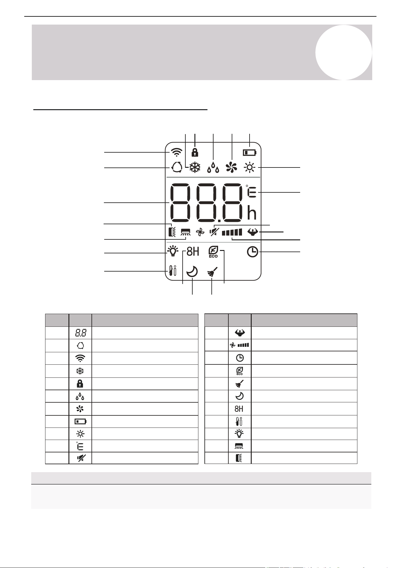
Remote Controller LED Screen & Icons
Note on Illustrations
The illustrations in this manual are strictly for explanatory purposes. The actual display and some functions of
the remote controller may vary according to the manual purchased.
8
Air Conditioner Installation & User Manual
10
3
4
5
6
Auto mode
Cooling mode
Signal transmit indicator
Dry mode
Fan Only mode
7
8
9
Heating mode
ECO mode
Self-Clean function
Unit of temperature (°C/°F)
2
1
12
11
Temperature indicator
Battery level indicator
Mute function
Turbo mode
Child lock indicator
15
16
18
17
13
14
21
22
19
20
Up-Down swing indicator
Left-Right swing indicator
Timer active indicator
LED display on/off
Sleep function
8°C (46°F) Heating function
I Feel/Follow Me mode
Fan speed (Auto or Fixed)
No.
Icon
Description
No.
Icon
Description
5
Operating Instructions
9
Air Conditioner Installation & User Manual
Signal
receptor
DI
SPLAY
3D
HEALTH
Y
ON/O
FF
SWI
NG
FAN
TI
M
ER
SU
PE
R
SL
EE
P
M
OD
E
EC
O
CLOC
K
Replace Batteries
Slide the battery cover on the rear of the remote down in the direction of the arrow. Install batteries according to
the depicted directions (+ and -) as shown on the remote controller. Slide the cover back into place.
Use 2x AAA batteries. Do not use re-chargeable batteries. Replace the old batteries with new ones of
the same type when the display is no longer working. Do not dispose of batteries as unsorted
municipal waste. Disposal of such waste separately for special treatment is necessary. If the system
will not be used for a long time, remove the batteries to prevent leakage.
Note: Remove batteries to
avoid leakage damage
when not being used for a
long time.
Configure Remote Controller Settings (Some Models)
Depending on the system, the control type (Cooling Only or Heat Pump) and the unit of temperature (°C or °F)
can be configured using the controller buttons. Operate as below. Complete the configuration as soon as the
batteries are inserted into the remote.
Remove the batteries and re-insert them to reprogram as many times as needed.
Operate the Remote Controller Successfully & Safely
Turbo
Turbo (press)
Functional Result
Press and Hold
Mode
Mode
When flashes, Cooling Only mode
When flashes, Heating Only mode
After 5 seconds, enter Change mode
Switch between °C and °F units
• Ensure no objects come between the remote controller and signal.
• Keep the remote at least 3 feet (1 m) away from televisions and other electrical
appliances.
• Always direct the remote controller toward the air conditioner.
• Do not leave the remote controller exposed to sun rays.
Note: Place the remote controller inside
the cradle when not in use (may be sold
separately).
5
Operating Instructions
Caution
10
Air Conditioner Installation & User Manual
flaps
Horizontal
Flap
movement
deflectors
Vertical
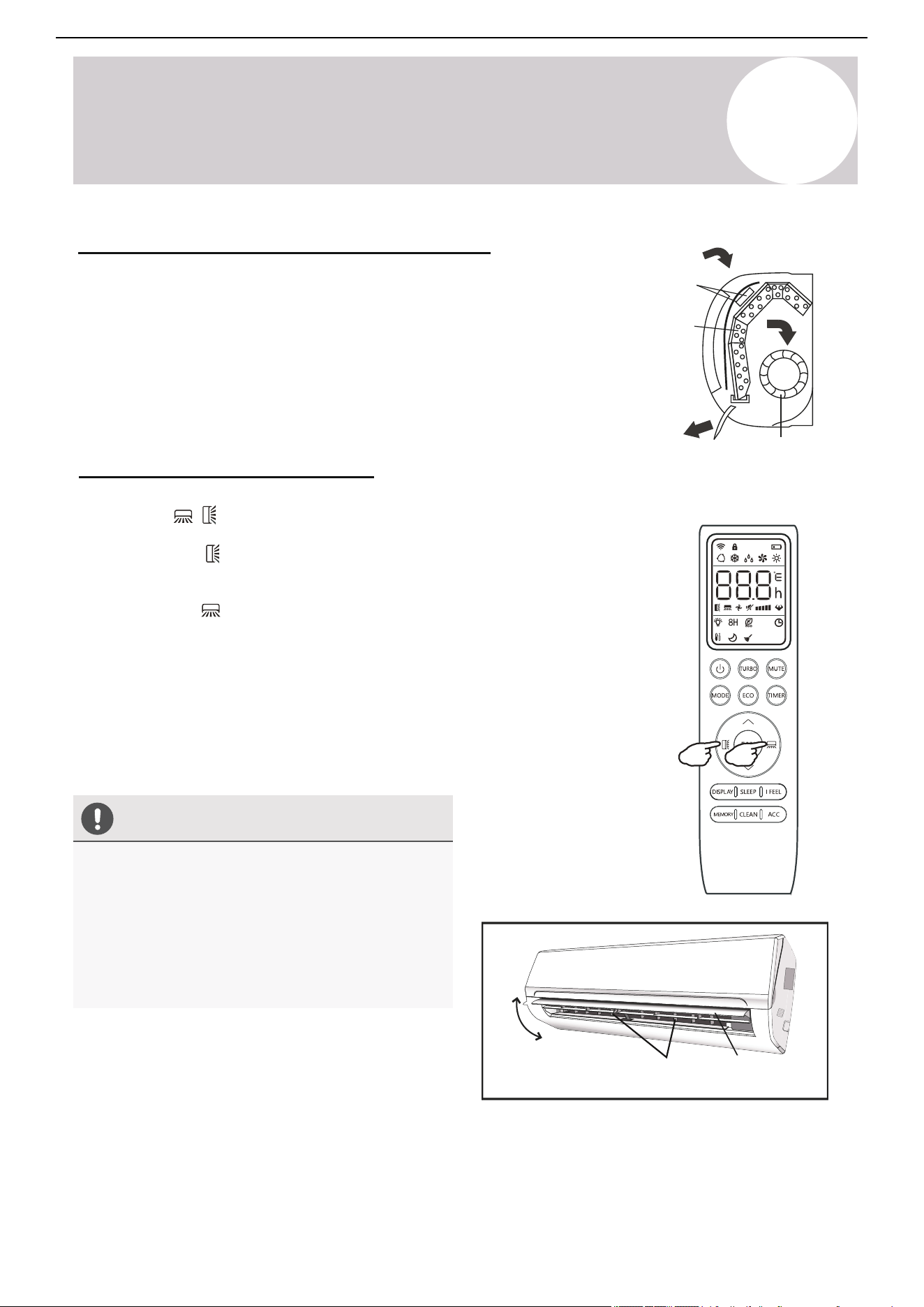
Regarding the Airflow of the Indoor Unit
The air that is pulled in by the fan (the "return air") enters the grille and is
passed through the filter. The air is then cooled/dehumidified/heated through
the heat exchanger.
The direction of the air output is manipulated up and down by the motorized
louver, as well as left to right by the manually controlled vertical deflectors.
Some models may come with "dual-swing" capability, which offers both a
horizontal and vertical motorized air flow swing.
Control the System's Airflow
1. Press the buttons to activate the air direction adjusters.
Press the Swing button to trigger the horizontal flaps to swing up and down.
Press the button again to stop the swing movement at the current angle.
Press the Swing button to trigger the vertical flaps to swing left and right.
Press the button again to stop the swing movement at the current angle.
2. If the vertical deflectors, which are located underneath the flaps, are adjusted
manually, they can be used to fix the airflow in a certain vertical position before
turning the system on.
Note: For some models, press either of the Swing buttons for > 3 seconds to
allow more fine adjustment of the airflow angle.
Filter
Heat
Fan
• Do not manipulate the louvers themselves
manually or serious damage may occur.
• Only make deflector adjustments when the
system is switched off.
• Never poke fingers, sticks, or other objects into
the air inlet/outlet vents.
Page 12
4
Operating Instructions
CAUTION
2. If the vertical deflectors (which are located
underneath the flaps) are adjusted manually,
they can be used to fix the airflow in a certain
vertical position before turning the system on.
Regarding the Airflow of the Indoor Unit
The air that is pulled in by the fan (the “return air”) enters the
grille and is passed through the filter. It is then
cooled/dehumidified/heated through the heat exchanger.
The direction of the air output is manipulated up and down by the
motorized louver, and left to right via manually controlled vertical
deflectors. Some models may come with “dual-swing” capability,
which offers both a horizontal and vertical motorized air flow swing.
Controlling the System’s Airflow
1. Pressing the buttons activates the air direction adjusters.
• Press the Swing button to trigger the horizontal
flaps to swing up and down. Press this button again
to stop swing movement at the current angle.
• Press the Swing button to trigger the vertical
flaps to swing left and right. Press this button again
to stop swing movement at the current angle.
Filter
Heat
Fan
• Do not manipulate the louvers themselves
manually, or serious damage may occur.
• Deflector adjustments should be made
only when the system is switched off.
• Never poke fingers, sticks, or other
objects into the air inlet/outlet vents.
Flaps
Horizontal
Flap
Movement
Deflectors
Vertical
Note: On some models, long-pressing either of the SWING buttons
for >3 seconds allows more fine adjustment of airflow angle.
Owner’s
Manual
5
Operating Instructions
11
Air Conditioner Installation & User Manual
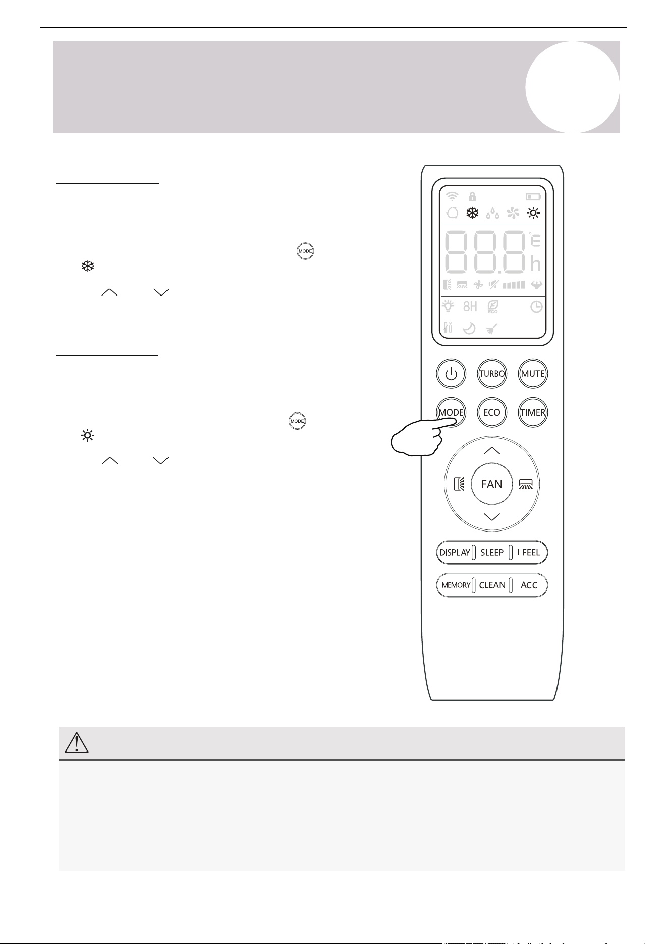
Cooling Mode
Cooling mode utilizes the heat pump to cool the room while also
reducing the humidity of the air in the room.
Use the
and
buttons to set a temperature lower than that
of the room.
Heating Mode
Heating mode utilizes the heat pump to warm the air in the room
by reversing the cooling cycle.
Use the and buttons to set a temperature higher than
that of the room.
Note: The system may take up to 10 minutes before it begins
delivering heat, allowing the coil to warm up and prevent cold
airflow.
Fan speed is not available to the user in the same way as
Cooling mode. Rather, the fan will blow out air at a speed that is
in proportion to how much the heat exchanger has been
warmed up to.
Note
In Heating mode, the appliance will periodically enter a defrost cycle, which is essential in order to
clean frosting off the condenser and recover heat exchange capabilities. The process is normal and
lasts for 2-10 minutes.
During defrosting, the indoor unit's fan will cease operation. After the cycle is completed, the system will
resume its normal Heating mode operation automatically. Press the ECO button 10 times in 8 seconds
to trigger a forced defrost.
To put the system into Cooling mode, press the button until
the symbol appears on the remote controller's display.
To put the system in Heating mode, press the button until
the symbol appears on the remote controller's display.
Page 15
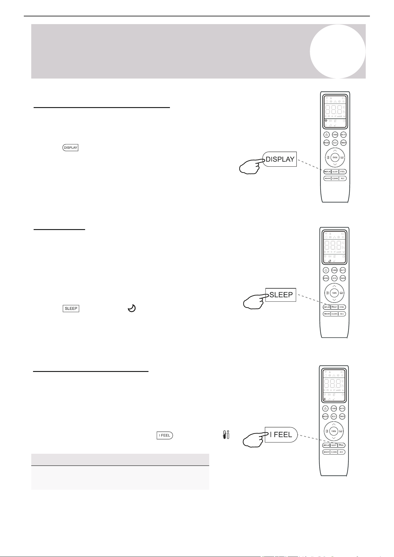
Turning the Display On or Off
4
Operating Instructions
button, and the
Press this button again to exit from this mode.
symbol will appear on the display.
The LED display on the front panel of the
system can be turned on or off as desired.
To do so, press the button in order to
switch off the LED display on the front panel.
This button can be pressed again to turn the
LED display back on again.
SLEEP Mode
Sleep mode is generally meant for periods of lesser
cooling/heating requirements, such as during typical
sleeping hours. This mode will result in decreased
energy use, and can only be activated via remote control.
After 10 hours in sleep mode, the air conditioner will
revert back to the previously set mode.
To put the system into sleep mode, press the
button, and the icon will appear on the display.
I FEEL - To Ensure Comfort
The I FEEL feature enables the remote to act as
the temperature sensor and relay the current air
temperature of where the remote is physically
placed within the room. In some cases, this can
aid with reducing thermal drift between the set
temperature and the actual room temperature.
In order to activate this feature, press the
NOTE
The I FEEL feature will automatically de-activate
itself 8 hours later (or 2 hours on some models).
Owner’s
Manual
5
Operating Instructions
(Flash)
△T (RT-ST)
→MODE
△T>2°F
Cooling
-2°F ≤ △T ≤ 2°F
Fan-Only
△T<2°F
Heating
Auto Mode
In Auto mode, the system selects either Cooling, Heating, or
Fan-Only mode based on the delta-T (△T ), which is the
difference between the room temperature and set temperature.
12
Air Conditioner Installation & User Manual
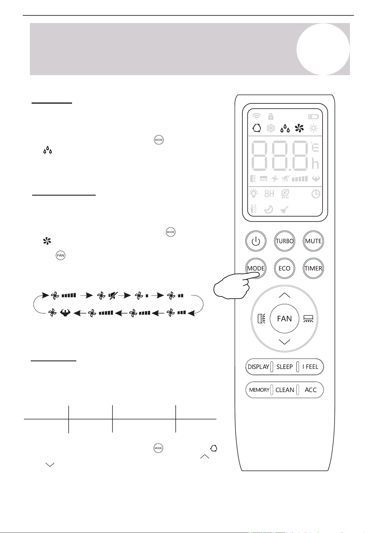
Use the Fan-Only mode to set the system to use only air
ventilation and no heating or cooling.
Use the button to set the desired fan speed. The system
will cycle from Auto > Mute > Low > Low-Mid > Mid > Mid-High
> High > Turbo
To put the system in Fan-Only mode, press the button until
thethe symbol appears on the remote controller's display.
Dry Mode
Dry mode is a limited function that can rapidly reduce the
humidity/moisture of the room.
Fan-Only Mode
To put the system into Dry mode, press the button until
the symbol appears on the remote controller's display.
An automatic preset of this mode activates.
To put the system in Auto mode, press the button until the
symbol appears on the remote controller's display. Use the
and buttons to set the desired room temperature.
Page 14
symbol appears on the
DRY Mode
Dry mode is a limited function that can rapidly
reduce the humidity/moisture of the room.
To put the system into dry mode, press the
button until the
remote’s display.
4
Operating Instructions
Use the
speed. The system will cycle from AUTO→MUTE→
LOW→LOW-MID→MID→MID-HIGH→HIGH→TURBO
button to then set the desired fan
An automatic preset of this mode is then activated.
FAN-ONLY Mode
Fan-only mode is used to set the system to use
only air ventilation and no heating or cooling.
To put the system into fan-only mode, press
the button until the symbol
appears on the remote’s display.
AUTO Mode
In Auto mode, the system selects cooling, heating, or
fan-only mode based on the delta-T (△T), which is the
difference between Room Temperature & Set Temperature.
→MODE
△T (RT-ST)
△T>2°F △T<2°F
Cooling Heating
-2°F ≤ △T ≤ 2°F
Fan-Only
To put the system into AUTO mode, press the
button until the symbol appears on the
remote’s display.
The and buttons can
then be used to set the desired room temperature.
(Flash)
Owner’s
Manual
5
Operating Instructions
Turn the LED Display On or Off
The LED display on the front panel of the system can be turned on or
off as desired.
Press the button in order to switch off the LED display on the
front panel. Press the button again to turn the LED display back on.
Sleep Mode
Sleep mode is generally meant for periods of lesser cooling/heating
requirements, such as during typical sleeping hours. This mode will
decrease energy use. The mode can only be activated via the
remote controller.
After 10 hours in Sleep mode, the air conditioner will revert back to
the previously set mode.
13
Air Conditioner Installation & User Manual
Note
The I Feel feature will automatically deactivate itself 8
hours later (or 2 hours on some models).
I Feel - To Ensure Comfort
button and theIn order to activate this feature, press the
icon will appear on the display.
Press the button and the symbol will appear on the
display. Press this button again to exit from this mode.
The I Feel feature enables the remote controller to act as the
temperature sensor and relay the current air temperature of where
the controller is physically placed within the room. In some cases,
this can aid with reducing thermal drift between the set
temperature and the actual room temperature.
5
Operating Instructions
Note
The ECO feature is available in both Cooling and Heating
mode.
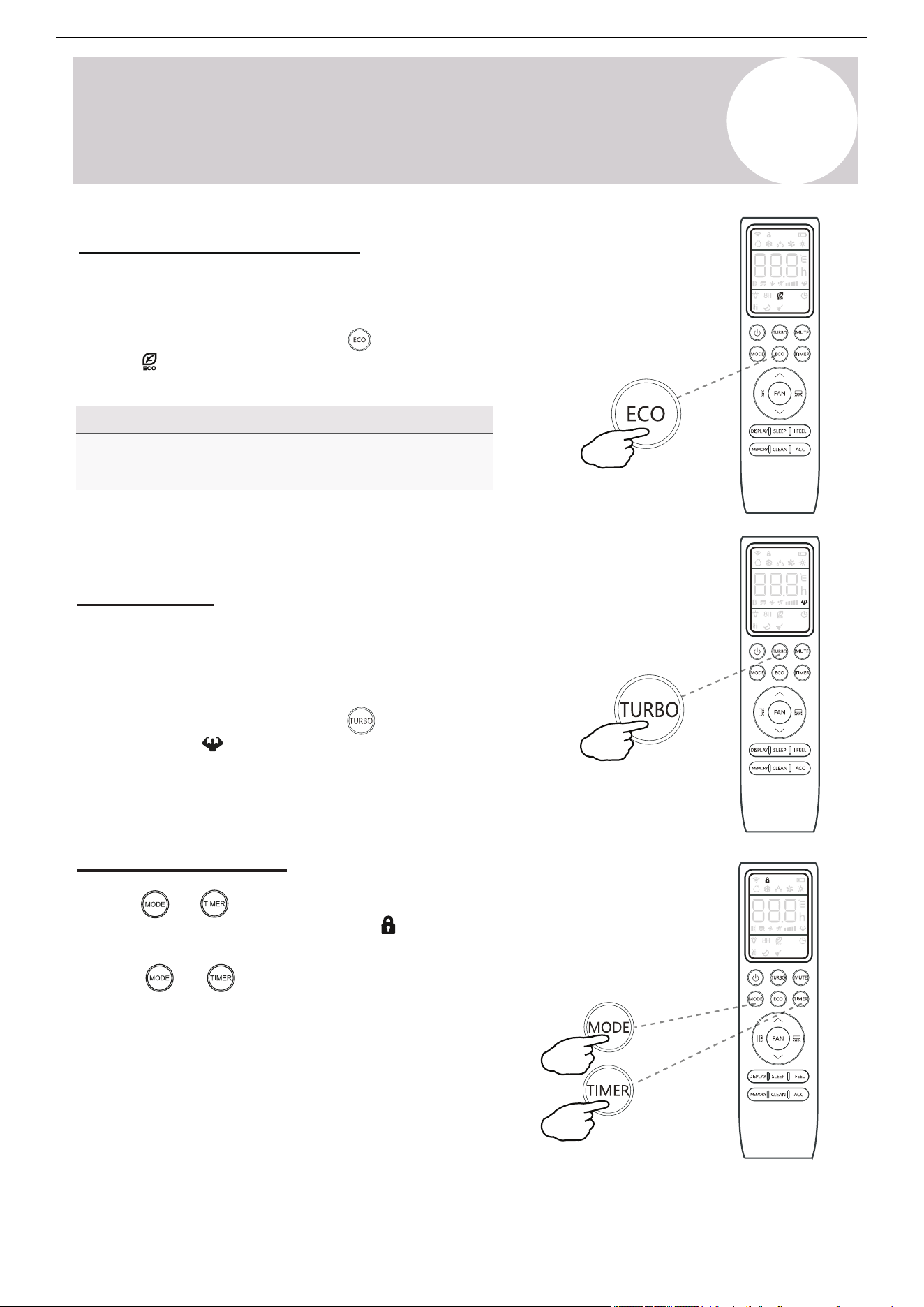
Turbo Option
Child-Lock Function
Pressing and buttons together will activate the child-lock
icon will display function. When this function is activate, the
and no single button will be active.
buttons together once more to deactivate Press the and
the child-lock function.
14
Air Conditioner Installation & User Manual
Energy Saver (ECO) Option
In this mode, the appliance will automatically manage its operation in
order to save energy.
To turn the ECO feature on, press the
button on the remote controller
and the
icon will appear. The system is now running in ECO mode.
The process can be repeated to turn it off.
In this mode, the appliance will operate using the highest fan
speed in order to maximize output and reach the set temperature
in the quickest way.
To turn the Turbo feature on, press the button on the remote
controller and the icon will appear. The system is now running in
Turbo mode. Repeat the process to turn off the feature.
5
Operating Instructions
15
Air Conditioner Installation & User Manual
button while the system is
symbol will then display flashing. The
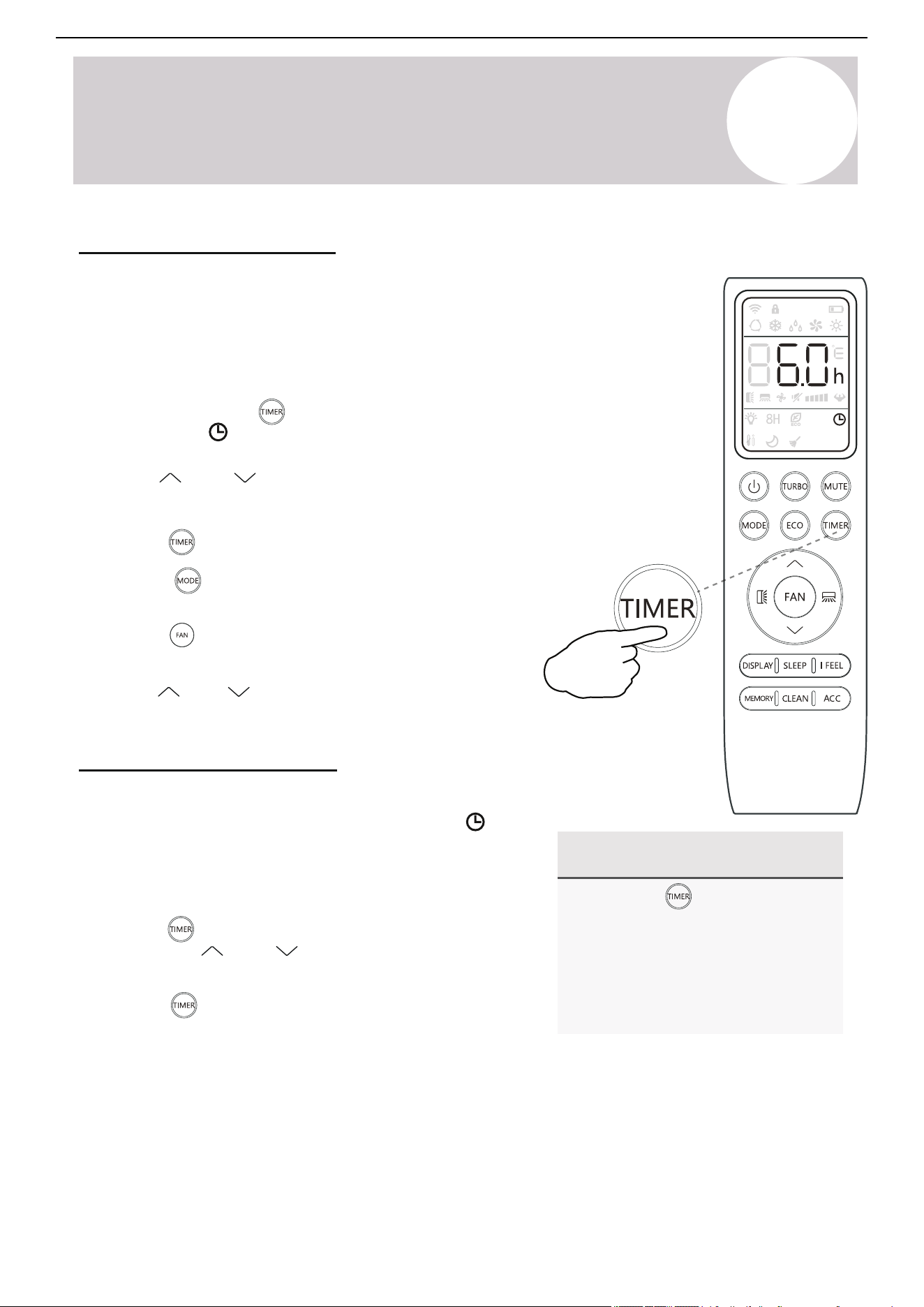
Use the Timer - Timer On
The Timer feature allows the user to set a time delay for the
system to turn itself on or off.
To set a timer for the system to turn itself on in a specified
amount of hours, follow these steps:
1. Begin by pressing the
powered off. The
default setting is 6 hours.
2. Use the and buttons to set the needed
time delay in 30 minutes increments.
button a second time to confirm. 3. Press the
4. Press the button to select the desired operating mode
that the unit should start up in.
5. Press the button to set the desired fan speed that the
unit should start up in.
6. Use the and buttons to set the desired operation
temperature. The unit is now primed.
Use the Timer - Timer Off
The Timer Off feature allows the appliance to turn itself off after a
determined amount of hours have passed. The symbol will
appear. To set a timer for the system to turn itself off in a
specified amount of hours, follow these steps:
1. Confirm that the appliance is on and running.
button to enter the prompt for switching off the
and buttons to configure the time
button again to confirm. Press it once more to
2. Press the
system. Use the
delay setting.
3. Press the
cancel the setting.
Note Regarding Timers
• Press the button to cancel at
any time in Timer Off.
• The programming will cancel if no
buttons are pressed after 5
seconds. This may require
restarting the process.
5
Operating Instructions
For 3 seconds...
16
Air Conditioner Installation & User Manual
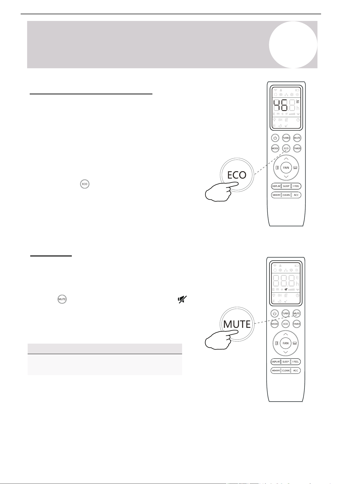
46°F Freeze Protection Function
Use this feature to prevent freezing while the user is away from
home. When turned on, it sets the system to maintain a
temperature of 46°F (8°C). If the unit is in standby, the setting
will automatically start the Heating mode when the room
temperature is equal to or lower than 46°F (8°C). The feature
will set the system back to standby when the room temperature
reaches 48°F (9°C).
If the room temperature is ever 64°F (18°C) or higher, then the
appliance will cancel or prevent this feature automatically.
Press and hold the button for 3 seconds to activate this
feature. Repeat this to deactivate the feature. Once activated,
46°F (8°C) will appear on the display.
Mute Mode
When the system is muted, the remote controller will display the
auto fan speed and the indoor unit will operate at its lowest fan
speed in order to minimize operation noise.
Press the button in order to activate this mode. The
icon will display to indicate that the system is muted.
Press either the Fan, Turbo, or Sleep button to cancel this
mode.
Note:
The Mute feature cannot be activated when the system is
in Dry mode.
5
Operating Instructions
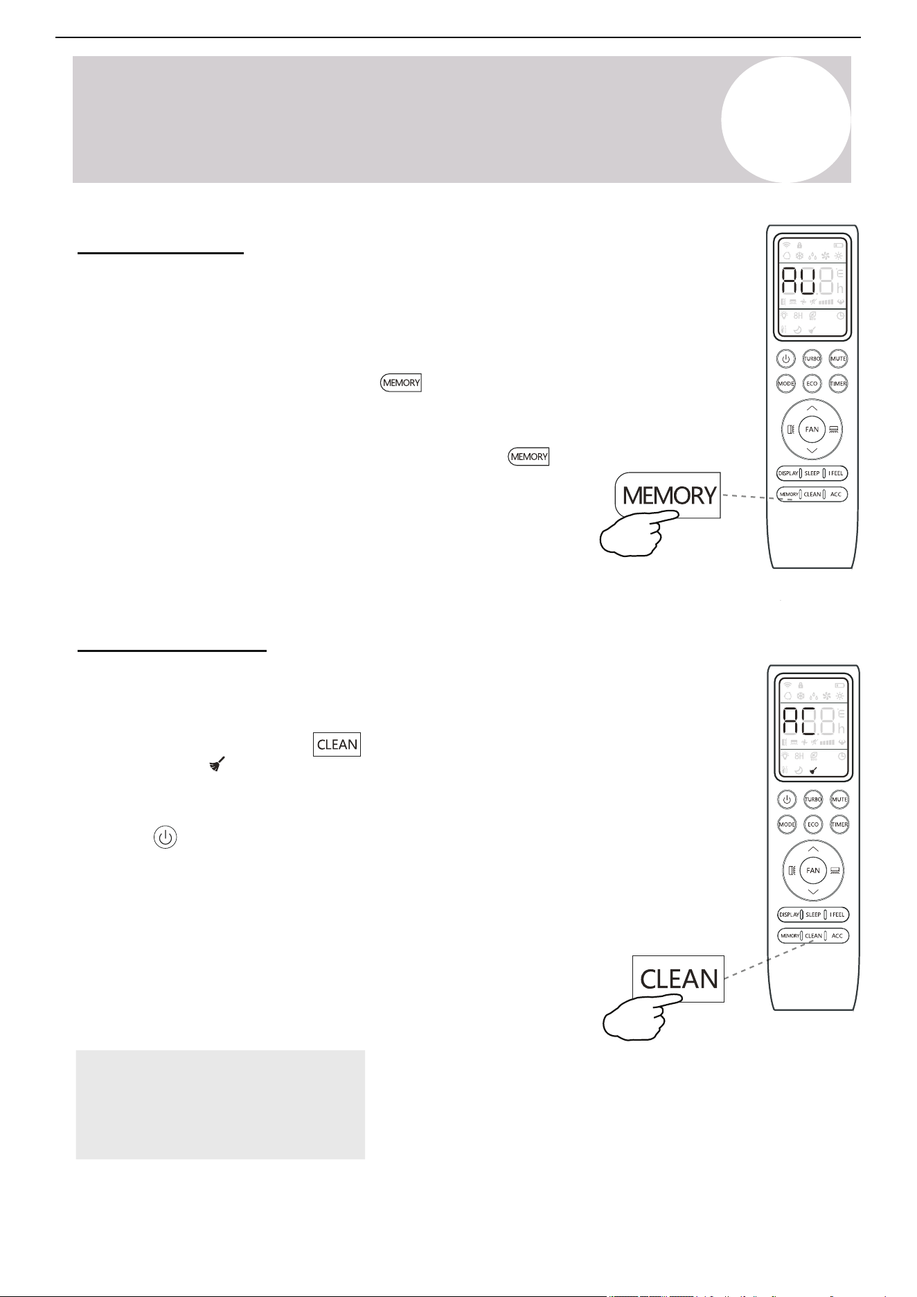
Memory Feature
17
Air Conditioner Installation & User Manual
The Memory feature enables the user to store their favorite settings and
reconfigure the system to the same parameters with the press of a single button.
Each mode (Heat / Cool / Fan / Dry) can store a unique setting.
To use this feature, enter the desired mode and set the system to the
preferred configuration. Press and hold the button for 3 seconds to store
button to
the configuration. The system will flash "AU" to acknowledge that the
configuration has been stored successfully.
Enter the desired mode (Heat / Cool / Fan / Dry) and press the
activate the stored configuration.
Self-Clean Feature
This feature helps remove some of the accumulated dust, dirt, bacteria,
and other microbial contents from the indoor evaporator.
To activate this feature, press the button until a beep is heard
from the unit. The
icon and AC displays on the unit and
remote controller. This procedure will operate for approximately 30
minutes before returning to the preset mode.
Press the button to cancel this feature during the process. Two
beeps will be emitted from the machine when it is finished or canceled.
This procedure can result in some uncommon noise coming from the
machine. This noise is normal as a side effect of the plastics expanding
and contracting due to reactions with heat and cold.
Only use this function when the indoor temperature is under 86°F (30°
C) and outside temperature is between 41-86°F (5-30°C).
It is suggested to run this feature once every 3 months.
Note:
This feature does not replace the
requirement of proper periodic
maintenance and cleaning, especially
for dusty/high-particle environments.
Page 21
Any accessorial electrostatic or deodorizing
filters, if installed, are not washable and
should be replaced once every 6 months.
Interior of the Indoor Air Handler
In addition to the filters, the interior of the indoor unit itself as well as the inner coil should be
inspected every season. The front panel can be disconnected and removed from the top hinge
where the pegs connect. This will allow for easier inspection of the interior and behind the air
filters. The interior should be cleaned with damp cloth and neutral soaps. Do not use any sort
of aggressive solvents or detergents. Only a soft cloth that is lightly dampened should be used.
Periodic Maintenance Is Essential For The System!
Maintaining the air conditioner will ensure that is stays efficient. Before carrying out any sort
of maintenance, always ensure that the power supply to the system is turned off for >5 minutes.
Wear safety gloves when working on the equipment, due to sharp aluminum fin edges of the coil.
Indoor Unit
Anti-Dust Filters (Inspect once every 2 weeks)
5
Maintenance of the Air Conditioner
1. Approach the interior unit to reach the top
area, and grasp both the exposed handles.
2. Gently remove the single anti-dust filter by
pulling upwards and backwards as depicted.
3. The filters are washable and should be
cleaned with warm water (under 113°F).
4. Leave the filters to dry in a cool, dry place.
5. Afterwards, re-insert the filter into the same
location after it has sufficiently dried.
BEFORE CLEANING OR MAINTENANCE
ALWAYS TURN OFF YOUR AIR CONDITIONER SYSTEM AND DISCONNECT ITS POWER SUPPLY
BEFORE PERFORMNG CLEANING OR MAINTENANCE. DO NOT SPRAY WATER DIRECTLY NEAR
THE INDOOR UNIT, AS IT CAN DAMAGE INSULATION AND ELECTRICAL COMPONENTS.
Maintenance
Instructions
Handles
Anti-Dust Filter
+
Louver
Deflector Assembly
Bottom Plate
Wash with room
temperature water
5
Operating Instructions
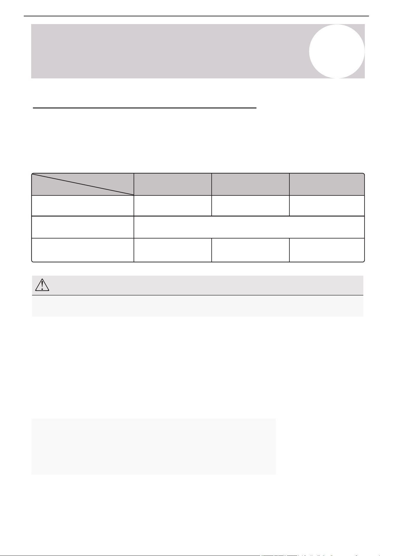
Operating
Temperature
Mode
Operational Room
Temperature Range
Remote Control Setting Range
Ambient Outdoor Temperature
Cooling Mode
63-90°F
(17-32°C)
61-86°F
(16-30°C)
5-122°F
(-15-50°C)
-22-86°F
(-30-30°C)
32-80°F
(0-27°C)
Heating Mode
Drying Mode
63-90°F
(17-32°C)
5-122°F
(-15-50°C)
18
Air Conditioner Installation & User Manual
Important Note Regarding Operating Temperatures
The system is designed to run within a certain range of temperatures, which are listed below. The system has
built-in protections that may stop the appliance when the ambient temperatures goes outside of these ranges.
Inverter Air Conditioner
Note
The system will restart after a 3-min delay if you stop and restart the air conditioner or change its mode (as
protection for the compressor).
Testing and rating agencies develop standard rating conditions to obtain full system-rated capacity and
efficiency. Within certain limitations, variable speed compressors compensate the deviations from the rating
conditions, especially the atmospheric conditions.
Heat pump systems function by exchanging energy between the indoor air and outdoor ambient air
(atmospheric) in the form of heat. The system's net cooling or heating capacities and efficiencies change by
atmospheric conditions, as well as the indoor air conditions, such as temperatures and humidity levels.
Professional individuals determine the capacity of the system required for a specific area or application using
detailed calculations, which are based on several internal and external factors.
To further optimize the performance of the unit, complete the following:
• Keep doors and windows closed.
• Use Timer On and Timer Off functions to limit energy usage.
• Do not block air inlets or outlets.
• Regularly inspect and clean air filters.
6
Maintenance
19
Air Conditioner Installation & User Manual
Handles
Anti-dust filter
+
Louver
Deflector assembly
Bottom plate
Wash with room
temperature water
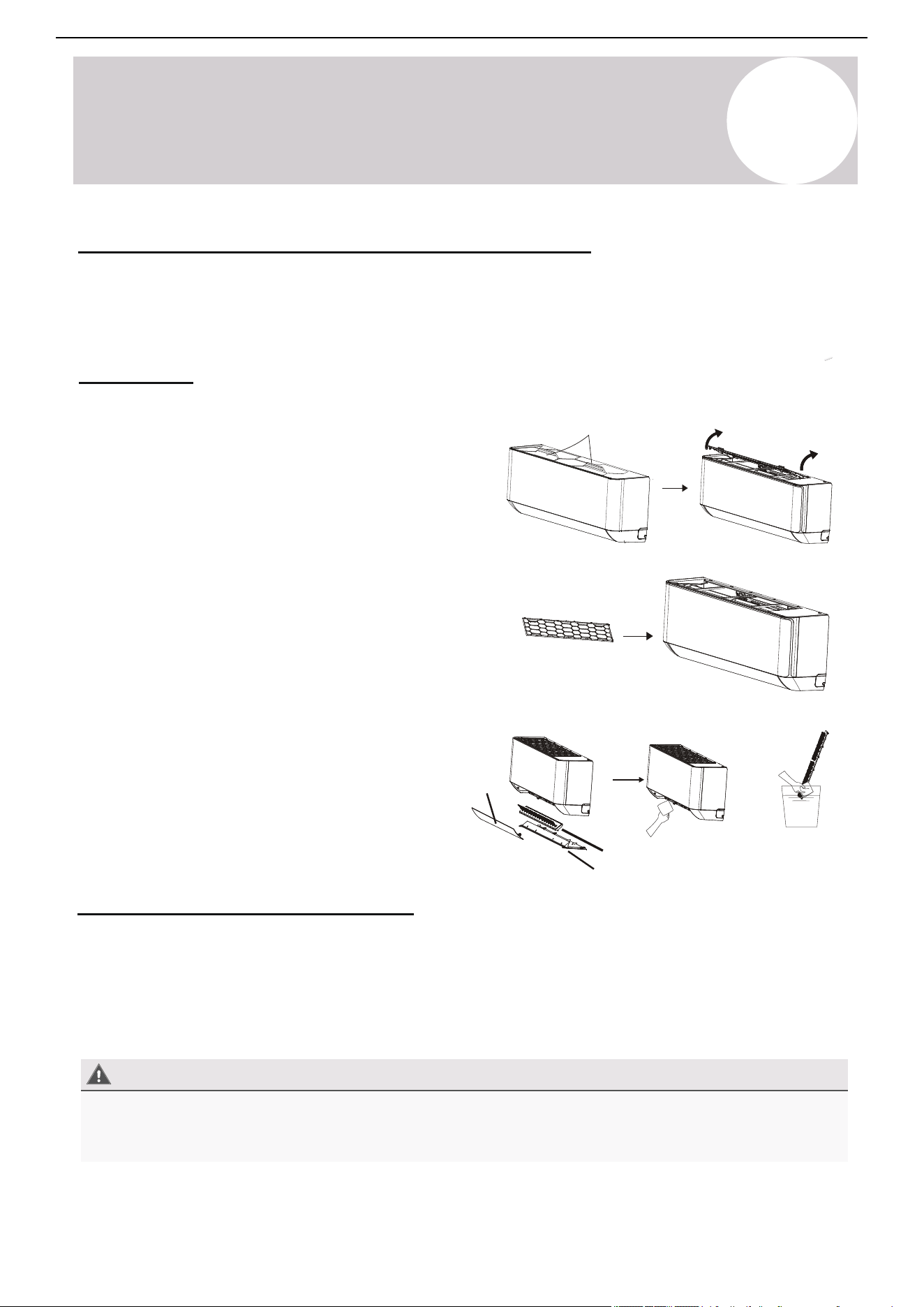
Before Cleaning or Maintenance
Always turn off the air conditioner system and disconnect its power supply before cleaning or performing
maintenance. Do not spray water directly near the indoor unit, as it can damage insulation and electrical
components.
In addition to the filters, inspect the interior of the indoor unit as well as the inner coil every season. Disconnect
the front panel and remove the top hinge where the pegs connect. This will offer easier inspections of the
interior and behind the air filters. Clean the interior with a damp cloth and neutral soaps. Do not use any types
of aggressive solvents or detergents. Only use a soft cloth that is lightly damp.
Interior of the Indoor Air Handler
Periodic Maintenance is Essential for the System!
1. Reach for the top area of the interior unit and grasp both
the exposed handles.
2. Gently remove the single anti-dust filter by pulling
upwards and backwards as shown in the illustrations.
3. Clean the filters with warm water (under 113°F / 45°C).
Note: The filters are washable.
4. Leave the filters to dry in a cool, dry place.
5. After, re-insert the filter into the same location after it has
sufficiently dried.
Note:
Accessorial electrostatic or deodorizing filters are not
washable and should be replaced every 6 months.
Maintaining the air conditioner will ensure that the system stays efficient. Before carrying out any sort of
maintenance, ensure that the power supply to the system is turned off for > 5 minutes. Wear safety gloves when
working on the equipment, due to sharp aluminum fin edges of the coil.
Indoor Unit
Anti-Dust Filters (Inspect once every 2 weeks)
7
A2L Refrigerants
20
Air Conditioner Installation & User Manual
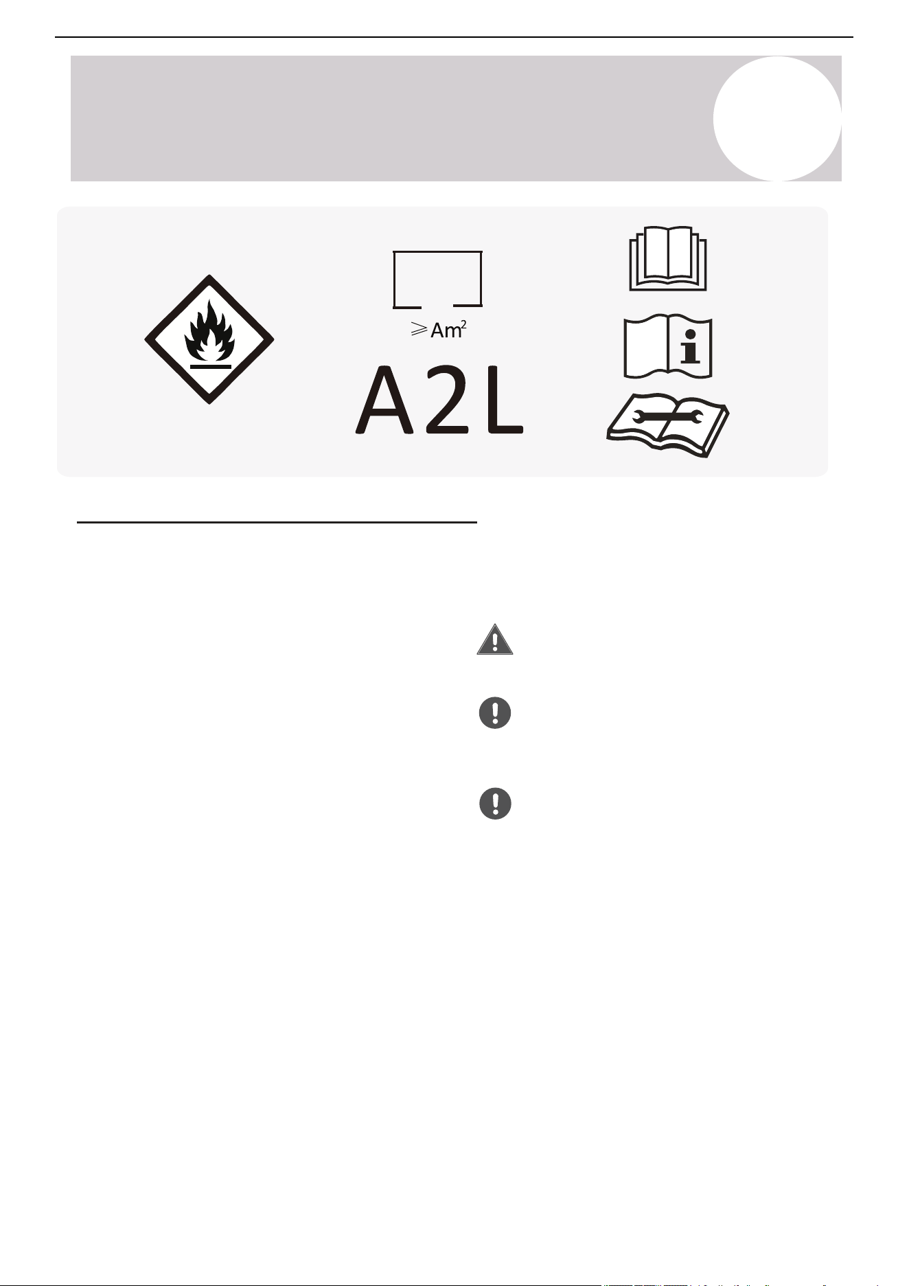
Safety Information for A2L Refrigerants
Because the system contains R-454B refrigerant, read and observe the following notices. Venting any type of
refrigerant into the atmosphere is always illegal and punishable under federal and local regulations. Always read
and obey all applicable local EPA laws.
• Refer to this manual for the required installation
space dimensions, including the minimum
clearance distances from adjacent structures.
• Install, operate, and store the appliance in a room
following the minimum room area requirements
(See page 31).
• Keep the length of the refrigerant piping to a
minimum.
• Protect the refrigerant piping from physical
damage. In addition, if the area of the space is
smaller than the minimum, ensure the installation
occurs in a ventilated space.
• Ensure the installation complies with all applicable
national refrigerant regulations.
• Ensure all mechanical connections remain
accessible for maintenance.
• Follow the instructions in this manual for proper
handling, installation, cleaning, maintenance, and
disposal of the refrigerant.
• Confirm that all ventilation openings remain
unobstructed.
Perform the servicing only in accordance with
the manufacturer's recommendations.
Store the appliance in a well-ventilated area
with a room size that meets the minimum
requirements specified for operation.
Store the appliance in a room free of
continuously operating open flames (e.g., an
active gas appliance) and ignition sources
(e.g., an operating electric heater).
• Individuals working on refrigerant circuits must
hold a valid, up-to-date certification from an
industry-accredited assessment authority. They
must verify their competence in handling
refrigerants per the recognized assessment
specifications of the relevant industrial sector.
• Perform service operations strictly in accordance
with the manufacturer's recommendations.
• If maintenance and repairs require assistance
from additional qualified personnel, conduct the
tasks under the supervision of a certified
professional competent in handling flammable
refrigerants.

Page 22
Safety
Information
6
Considerations for A2L Refrigerants
Safety Information for A2L Refrigerants
Because your system contains R-454B refrigerant, the following notices should be read and followed.
It must be noted that venting any type of refrigerant into the atmosphere is always illegal and is
punishable under federal and local regulations. Always read and obey all applicable local EPA laws.
▪ Refer to this manual for the required
installation space dimensions, including
the minimum clearance distances from
adjacent structures.
▪ The appliance must be installed, operated,
and stored in a room with a floor area of at
least the minimum allowed (see Page 31).
▪ The length of the refrigerant piping should
be kept to a minimum.
▪ The refrigerant piping must be protected
from physical damage and should not be
installed in an unventilated space if the area
of the space is smaller than the minimum.
▪ Installation must comply with all applicable
national refrigerant regulations.
▪ All mechanical connections must remain
accessible for maintenance.
▪ Follow the instructions in this manual for
proper handling, installation, cleaning,
maintenance, and disposal of the
refrigerant.
▪ Ensure that all ventilation openings remain
unobstructed.
Any individual working on a refrigerant circuit
must hold a valid, up-to-date certification from
an industry-accredited assessment authority,
verifying their competence in handling
refrigerants per the recognized assessment
specifications of the relevant industrial sector.
Service operations must be performed strictly
in accordance with the manufacturer's
recommendations. Maintenance and repair
tasks requiring assistance from additional
qualified personnel must be conducted under
the supervision of a certified professional
competent in handling flammable refrigerants.
Servicing must be performed only in accordance
with the manufacturer's recommendations.
The appliance must be stored in a well-ventilated
area with a room size that meets the minimum
requirements specified for operation.
The appliance must be stored in a room free of
continuously operating open flames (e.g., an
active gas appliance) and ignition sources
(e.g., an operating electric heater).
7
A2L Refrigerants
21
Air Conditioner Installation & User Manual
Service Information for A2L Refrigerants
• Store the appliance in a manner that prevents
mechanical damage.
• Competent personnel must carry out any work
procedures affecting safety measures.
Warning
• Do not attempt to accelerate the defrosting
process or remove frost manually.
• Follow the manufacturer's recommended
procedures.
• Store the appliance in a room free of continuously
operating ignition sources (e.g., open flames,
active gas appliances, operating electric heaters).
• Do not pierce or incinerate the appliance or its
components.
• Be aware that refrigerants may be odorless.
• Area Inspection:
o Before servicing systems containing flammable
refrigerants, perform safety checks to minimize
the risk of ignition. When repairing the
refrigeration system, observe all the following
precautions before beginning any work.
• Work Procedure:
• Area Ventilation:
o Ensure that the area is free from flammable
materials and conditions are controlled to
maintain a safe working environment.
• Checking for Refrigerant Presence:
o Monitor the work area for refrigerant leaks using
an appropriate refrigerant detector before and
during service.
o Ensure the leak detection equipment used is
suitable for flammable refrigerants (i.e., non-
sparking, adequately sealed, or intrinsically safe).
• Presence of Fire Extinguisher:
o If performing any hot work on the refrigeration
equipment or its associated components, ensure
appropriate fire extinguishing equipment is readily
available. Position a dry powder or CO
2
fire
extinguisher adjacent to the charging area.
• Elimination of Ignition Sources:
o Do not use ignition sources that could pose a fire
or explosion risk when conducting any work
involving the exposure of refrigeration system
piping.
o Keep all potential ignition sources, including
smoking, at a safe distance from the installation,
repair, removal, disposal areas, and locations
where refrigerant may be released unintentionally
into the surrounding space.
o Before commencing work, inspect the area to
ensure that no flammable hazards or ignition
risks are present.
o Clearly display "No Smoking" signs in the work
area.
o Conduct all work under a controlled process to
minimize the risk of flammable gas or vapor from
being present during service.
o Inform all maintenance personnel and individuals
in the vicinity about the nature of the work being
performed.
o Avoid working in confined spaces whenever
possible.
o Section off the work area to prevent unauthorized
access.
• General Work Area:

Page 25
▪ Cabling: Ensure that cabling is not exposed to
wear, corrosion, excessive pressure, vibration,
sharp edges, or other adverse environmental
factors. Consider the long-term effects of aging
and continuous vibration from components such
as compressors or fans.
▪ Detection of Flammable Refrigerants:
Under no circumstances should potential sources
of ignition be used for refrigerant leak detection.
Halide torches or any other flame-based
detection devices must not be used.
▪ Leak Detection Methods: The following
methods are approved for detecting leaks in
systems containing flammable refrigerants:
◦ Electronic Leak Detectors: Must be used for
detecting flammable refrigerants. However, they
may require recalibration to maintain adequate
sensitivity.
- Detection equipment must be calibrated in a
refrigerant-free area.
- Ensure that the detector does not pose an
ignition risk and is compatible with the refriger-
ant in use.
- The detector must be set to a percentage of the
refrigerant's Lower Flammability Limit (LFL)
and calibrated to confirm that the appropriate
gas concentration does not exceed 25% of the
LFL.
◦ Leak Detection Fluids: Suitable for most
refrigerants but must not contain chlorine, as
chlorine can react with the refrigerant and
corrode copper piping.
◦ Safety Precautions: If a leak is suspected, all
open flames must be removed or extinguished. If
a refrigerant leak requiring brazing is detected, all
refrigerant must be fully recovered or isolated
using shut-off valves to prevent accidental
release.
◦ Oxygen-Free Nitrogen (OFN) must be
purged through the system before and
during brazing.
▪ Removal and Evacuation: When
accessing the refrigerant circuit for
repairs or other procedures,
industry-standard practices must be
followed, with additional precautions for
flammability:
1. Recover the refrigerant into approved
recovery cylinders.
2. Purge the circuit using an inert gas
(such as OFN).
3. Evacuate the system.
4. Purge again with inert gas.
5. Open the circuit by cutting or brazing.
- The system must be flushed with OFN to
ensure safety. This process may need to
be repeated multiple times.
- Do not use compressed air or oxygen for
flushing.
• Flushing should be performed by:
1. Breaking the system vacuum with OFN.
2. Filling the system until the working
pressure is reached.
3. Venting to the atmosphere.
4. Pulling the system down to vacuum.
5. Repeating the process until no
refrigerant remains in the system.
- When the final OFN charge is
introduced, the system must be vented
to atmospheric pressure to allow for safe
work. This step is critical before
performing any brazing on pipework.
• Ensure the vacuum pump outlet is
positioned away from ignition sources
and that adequate ventilation is present.
6
Considerations for A2L Refrigerants
Safety
Information
7
A2L Refrigerants
22
Air Conditioner Installation & User Manual
• Ventilated Area:
o Ensure the work is conducted in either an open
area or in a space with adequate ventilation
before breaking into the system or performing any
heat-producing tasks.
o Maintain ventilation throughout the duration of the
work.
o Ensure the ventilation system effectively
disperses any released refrigerant and directs it
safely to an external atmosphere, if possible.
• Inspection of Refrigeration Equipment:
o When replacing electrical components, ensure
that they meet the correct specifications and are
suitable for its intended purpose.
o Follow the manufacturer's maintenance and
service guidelines.
o If unsure, consult the manufacturer's technical
support department for guidance.
• Inspections for Installations Using Flammable
Refrigerants: Perform the following inspections
for systems utilizing flammable refrigerants:
o Ensure that the refrigerant charge size complies
with the minimum room size requirements when
installing refrigerant-containing components.
o Verify that the ventilation equipment and exhaust
outlets are functioning properly and free from
obstructions.
o If using an indirect refrigerant circuit, inspect the
secondary circuit for any presence of refrigerant.
o Confirm that all equipment markings remain visible
and legible. Replace or correct any illegible
markings or signs.
• Inspection of Electrical Devices:
o Ensure the repair and maintenance of electrical
components include initial safety checks and a
thorough inspection of components.
o If the fault cannot be corrected immediately but
continuing work is necessary, implement a
temporary solution that is safe and effective.
o Report any temporary measures to the equipment
owner, ensuring all relevant parties are informed.
• Initial Safety Checks:
o Fully discharge the capacitors in a controlled
manner to prevent sparking.
o Verify that no live electrical components or
exposed wiring are present during system
charging, refrigerant recovery, or purging.
o Confirm that the earth bonding continuity is
maintained.
• Repairs to Sealed Components:
o Replace sealed electrical components, rather
than repair them.
• Repairs to Intrinsically Safe Components:
o Replace intrinsically safe components, rather
than repair them.
o Install the refrigeration piping and components in
locations where they are not exposed to
substances that could cause corrosion. If
exposure is unavoidable, verify that the
components are either made from corrosion-
resistant materials or are adequately protected
against corrosion.
Service Information for A2L Refrigerants (Continued)

7
A2L Refrigerants
23
Air Conditioner Installation & User Manual
• Cabling: Do not expose the cabling to wear,
corrosion, excessive pressure, vibration, sharp
edges, or other adverse environmental factors.
Consider the long-term effects of aging and
continuous vibration from components such as
compressors or fans.
• Detection of Flammable Refrigerants: Do not
use potential sources of ignition for refrigerant
leak detection under any circumstances.
• Leak Detection Methods: The following methods
are approved for detecting leaks in systems
containing flammable refrigerants:
o Electronic Leak Detectors: Use this method for
detecting flammable refrigerants. Note: They may
require recalibration to maintain adequate
sensitivity.
-- Calibrate the detection equipment in a
refrigerant-free area.
-- Ensure that the detector does not pose an
ignition risk and is compatible with the refrigerant
in use.
-- Set the detector to a percentage of the
refrigerant's Lower Flammability Limit (LFL). In
addition, calibrate the detector to confirm that the
appropriate gas concentration does not exceed
25% of the LFL.
o Leak Detection Fluids: This method is suitable
for most refrigerants but must not contain
chlorine. Note: Chlorine can react with the
refrigerant and corrode copper piping.
o Safety Precautions: If a leak is suspected,
remove or extinguish all open flames. If a
refrigerant leak requiring brazing is detected, fully
recover the refrigerant or isolate the refrigerant
using the shut-off valves to prevent accidental
release.
o Oxygen-Free Nitrogen: Purge oxygen-free
nitrogen through the system before and during
brazing.
• Removal and Evacuation: When accessing the
refrigerant circuit for repairs or other procedures,
follow the industry-standard practices, with
additional precautions for flammability:
1. Recover the refrigerant into approved recovery
cylinders.
2. Purge the circuit using an inert gas, such as OFN.
3. Evacuate the system.
4. Purge the circuit again using inert gas.
5. Open the circuit by cutting or brazing.
-- Flush the system with OFN to ensure safety.
Repeat this process multiple times if needed.
-- Do not use compressed air or oxygen for flushing.
• Flushing: Follow this flushing procedure:
1. Break the system vacuum with OFN.
2. Fill the system until the working pressure is
reached.
3. Vent the system to atmospheric pressure.
4. Pull the system down to vacuum.
5. Repeat this process until no refrigerant remains in
the system.
6. When the final OFN charge is introduced, vent the
system to atmospheric pressure to allow for safe
work. This step is critical before performing any
brazing on pipework.
Note: Position the vacuum pump outlet away from
ignition sources and ensure adequate ventilation.
Service Information for A2L Refrigerants (Continued)

Page 27
6
Considerations for A2L Refrigerants
Recovery Procedure: When removing refrigerant
from a system for servicing or decommissioning, the
following best practices must be observed to ensure
safety and compliance:
1. Safe Refrigerant Removal: All refrigerants must
be safely removed from the system following
proper handling procedures.
2. Use of Appropriate Recovery Cylinders: Only
approved refrigerant recovery cylinders must
be used.
A. Ensure that a sufficient number of cylin-
ders are available to accommodate the total
refrigerant charge from the system.
B. Each cylinder must be designated and
labeled for the specific refrigerant being
recovered (e.g., cylinders specifically designed
for refrigerant recovery).
C. Recovery cylinders must be equipped with a
pressure-relief valve and functioning
shut-off valves.
D. Empty recovery cylinders should be
evacuated and, if possible, pre-cooled
before the recovery process begins.
3. Recovery Equipment Requirements: The
recovery equipment must be:
A. In good working condition.
B. Accompanied by manufacturer-provided
operating instructions.
C. Suitable for recovering all appropriate
refrigerants, including flammable refrigerants
when applicable.
D. A calibrated weighing scale must be available
to monitor refrigerant recovery accurately.
E. Hoses must be equipped with leak-free
disconnect couplings and be in good
condition.
◦ Before using the recovery machine:
Verify that it is in proper working order
and has been properly maintained.
Ensure that any associated electrical
components are sealed to prevent
ignition in case of a refrigerant leak.
◦ If in doubt, consult the manufacturer.
4. Handling Recovered Refrigerant:
• It is vital that:
A. The recovered refrigerant must be
returned to the refrigerant supplier in
the correct recovery cylinder.
B. A waste transfer note must be
arranged for proper documentation
and disposal.
C. Do not mix refrigerants in recovery
units or cylinders under any
circumstances.
5. Compressor and Oil Removal:
• If compressors or compressor oils need
to be removed:
A. Ensure that they have been
evacuated to an acceptable level
to eliminate any remaining flammable
refrigerant within the lubricant.
B. The evacuation process must be
completed before returning the
compressor to the supplier.
C. Only electric heating should be
used to accelerate the evacuation of
refrigerant from the compressor
body. Open flames or ignition
sources must not be used.
• When draining oil from a system, the
process must be conducted safely and in
accordance with best practices.
Recovery Information for A2L Refrigerants
Safety
Information
7
A2L Refrigerants
24
Air Conditioner Installation & User Manual
Decommissioning Information for A2L Refrigerants
Decommissioning: Before starting the
decommission process, the technician must be fully
familiar with the equipment and its components.
Safely recover all refrigerant as a standard best
practice. Prior to decommissioning, collect an oil
and refrigerant sample for analysis if reclaimed
refrigerant is intended for reuse. Ensure electrical
power is available before beginning the
decommissioning process.
A. Familiarization: Understand the equipment, its
operation, and the decommissioning process before
beginning work.
B. Electrical Isolation: Disconnect the system from
the electrical supply to prevent accidental activation
during the procedure.
C. Pre-Procedure Safety Checks: Before
proceeding, ensure the following:
• Mechanical handling equipment is available if
needed for refrigerant cylinder transport.
• All required personal protective equipment
(PPE) is present and correctly used.
• A competent person supervises the entire
refrigerant recovery process.
• Recovery equipment and cylinders comply with
all relevant safety and regulatory standards.
H. Cylinder Fill Limits: Do not exceed 80% of the
cylinder's total volume when filing with liquid
refrigerant, allowing expansion.
I. Maximum Pressure Precautions: Do not
exceed the maximum working pressure of the
recovery cylinder at any time, even temporarily.
J. Finalizing the Recovery Process:
Once the cylinders are correctly filled and the
process is complete:
o Promptly remove the cylinders and
recovery equipment from the site.
o Close all isolation valves on the
equipment to prevent leaks.
D. Pump Down the Refrigerant System: If
possible, perform a pump-down procedure to
remove refrigerant from the system.
E. Alternative Method if Vacuum is Not Possible:
If a complete vacuum cannot be achieved, create a
manifold to facilitate refrigerant removal from
multiple points in the system.
F. Cylinder Positioning: Ensure the recovery
cylinder is placed on a scale before starting the
refrigerant recovery process.
G. Recovery Machine Operation: Start the
recovery machine and follow the manufacturer's
instructions for proper operation.
K. Handling Recovered Refrigerant: Recovered
refrigerant must not be recharged into another
refrigeration system unless it has been properly
cleaned and tested to ensure compliance with
safety and performance standards.
L. Labeling: Label the equipment indicating that it
has been decommissioned and emptied of
refrigerant. The label must include the
decommissioning date and signature of the
responsible technician. Ensure that the equipment
preserves labels indicating the presence of
flammable refrigerant, even after decommission.

7
A2L Refrigerants
25
Air Conditioner Installation & User Manual
Recovery Information for A2L Refrigerants
Recovery Procedure: When removing refrigerant from
a system for servicing or decommissioning, observe the
following best practices to ensure safety and
compliance:
1. Safe Refrigerant Removal: Safely remove all
refrigerants from the system following proper handling
procedures.
2. Use of Appropriate Recovery Cylinders: Only use
approved refrigerant recovery cylinders.
• Ensure that a sufficient number of cylinders are
available to accommodate the total refrigerant
charge from the system.
• Designate and label each cylinder for the specific
refrigerant being recovered. (e.g., cylinders
specifically designed for refrigerant recovery).
• Equip recovery cylinders with a pressure-relief
valve and functioning shut-off valves.
• Evacuate empty recovery cylinders. If possible,
pre-cool the recovery cylinders before the process
begins.
3. Recovery Equipment Requirements: The recovery
equipment must be:
• In good working condition.
• Accompanied by manufacturer-provided operating
instructions.
• Suitable for recovering all appropriate refrigerants,
including flammable refrigerants when applicable.
• Ensure a calibrated weighing scale is available to
monitor refrigerant recovery accurately.
• Equip hoses with leak-free disconnect couplings
and ensure they're in good conditions.
o Before using the recovery machine, verify
that it is in proper working order and has
been properly maintained.
o Ensure that any associated electrical
components are sealed to prevent ignition
in case of a refrigerant leak.
o If in doubt, consult the manufacturer.
4. Handling Recovered Refrigerant:
It is vital to:
• Return the recovered refrigerant to the
refrigerant supplier in the correct recovery
cylinder.
• Arrange a waste transfer note for proper
documentation and disposal.
• Do not mix refrigerants in recovery units or
cylinders under any circumstances.
5. Compressor and Oil Removal:
If compressors or compressor oils need to be
removed:
• Evacuate the compressor to an
acceptable level to eliminate any
remaining flammable refrigerant within the
lubricant.
• Complete the evacuation process before
returning the compressor to the supplier.
• Only use electric heating to accelerate the
evacuation of refrigerant from the
compressor body. Do not use open flames
or ignition sources.
• When draining oil from a system, conduct
the process safely and in accordance with
best practices.
7
A2L Refrigerants
26
Air Conditioner Installation & User Manual
WARNING
USAGE STATEMENT
• Use a flammable gas detector to check for potential leaks
before unloading and opening the container.
• Do not allow fire sources or smoking in the vicinity.
• Protect the pipework from physical damage. For flammable
refrigerants, do not install pipes in an unventilated space if it is
smaller than the minimum requirements in Annex GG. For A2L
refrigerants, you must install pipes that comply with 22.116. If
field charging is necessary, technicians must quantify the
impact of different pipe lengths on the refrigerant charge.
• Ensure the compliance of all national gas regulations.
• Ensure that mechanical connections made in accordance with
22.118 remain accessible for maintenance.
• Protect pipework, including piping material, routing, and
installation from physical damage during operation and
servicing. It must comply with all national and local codes and
standards, including:
o ASHRAE 15
o ASHRAE 15.2
o IAPMO Uniform Mechanical Code
o ICC International Mechanical Code
o CSA B52
o All field joints must be accessible for inspection before
being covered or enclosed.
• After completing the field piping installation for split systems,
the field pipework must undergo:
o Pressure testing with an inert gas.
o Vacuum testing before refrigerant charging, following
the required standards.
• Store the appliance in a way that prevents mechanical damage.
• Qualified personnel must carry out maintenance, service, and
repair operations according to Annex HH.
• Only competent individuals should perform safety-critical
procedures, including:
o Breaking into the refrigerant circuit
o Opening sealed components
o Opening ventilated enclosures
• Do not use unauthorized methods to complete cleaning or
accelerate defrosting. Follow only the manufacturer's
recommended procedures.
• Store the appliance in a room free of continuously operating
ignition sources (e.g. open flames, operating gas appliance,
electric heater).
• Do not pierce or burn any part of the system.
•
Minimum Installation Requirements: Install the equipment
within the minimum height and room area (for both operation
and storage) specified in the installation manual.
• Risk of Fire - Auxiliary Devices: Do not install ignition source
auxiliary devices within the ductwork, unless they are
specifically listed for this appliance. Refer to the installation
instructions.
• Mounting Clearance: Mount the system with the lowest
moving parts at least 8 feet (2.5 m) above the floor or grade
level.
• Risk of Electric Shock: Serious injury or death may occur.
Disconnect all remote electric power supplies before
performing any service.
• Risk of Fire - Flammable Refrigerant: Flammable refrigerant
is used. Ensure proper handling and disposal. Trained service
personnel must perform maintenance and repairs. Do not
puncture the refrigerant tubing.
• Risk of Fire - Proper Disposal Required: Dispose of the
system according to all applicable federal and local regulations.
• Risk of Fire - Service Precautions: Flammable refrigerant is
used. Refer to the service manual before attempting to service
this product.
• Risk of Fire - Compliance with Regulations: Follow all
handling instructions and comply with national regulations
when working with flammable refrigerants.
AVERTISSEMENT
• Ne pas utiliser de moyens non recommandés par le fabricant
pour accélérer le dégivrage ou nettoyer l’appareil.
• L’appareil doit être entreposé dans un endroit sans source
d’allumage fonctionnant en continu (par exemple: flamme
nue, appareil à gaz en marche, ou radiateur électrique en
marche).
• Ne pas percer ni brûler l’appareil.
• Attention: les frigorigènes peuvent être inodores.
COMPLIANCE
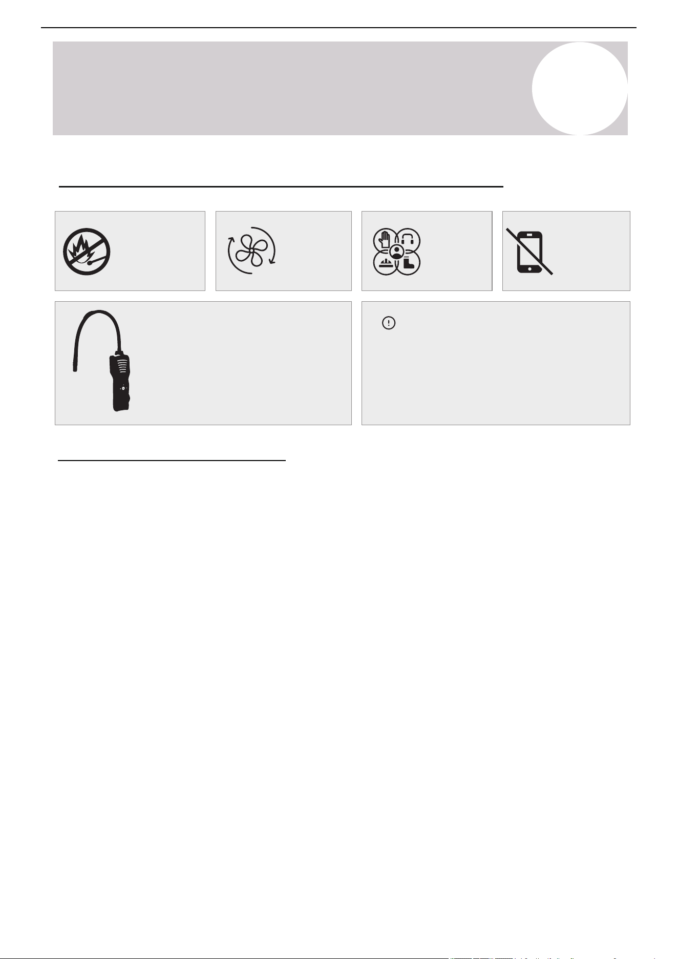
7
A2L Refrigerants
27
Air Conditioner Installation & User Manual
No flammable
sources
Preparation for Working on Systems with A2L Refrigerants
Ventilation
necessary
Wear
protective
gear
Do not use
electronics
near system
Refrigerant Leakage Detector
A handheld leak detector can aid with
tracing and isolating refrigerant leaks. It
is recommended to have one handy
whenever working on the system.
Determining Installation Location
Install the systems in suitable locations according
to the guidelines below. For the best results,
follow all the requirements for equipment
placement in this manual.
Installation Site Requirements
1. Ensure Proper Ventilation
• Ventilate the installation site well to allow safe
operation and prevent refrigerant accumulation.
2. Keep Away from Heat and Fire Hazards
• Keep all installation and maintenance sites for air
conditioners that use R-454B refrigerant away from
open flames or heat sources.
• To prevent ignition risks, technicians must avoid
locations near welding activities, smoking areas,
drying ovens, or any heat source exceeding 1,000°F
(538°C).
3. Implement Anti-Static Precautions
• Wear anti-static clothing and gloves to prevent static
discharge when handling and installing the unit.
4. Select an Accessible Installation Site
• The installation location must allow easy access for
maintenance.
• Do not surround indoor and outdoor units with
obstacles that restrict airflow.
• Keep away from heat sources and flammable or
explosive materials.
5. Refrigerant Leak Emergency Actions
• If the indoor unit leaks refrigerant during
installation, immediately shut off the
outdoor unit valve.
• All personnel must evacuate the area for
at least 15 minutes until the refrigerant
fully dissipates.
• If the product is damaged, transport it to a
maintenance station. Note: On-site
welding or refrigerant pipe repairs are
strictly prohibited.
6. Ensure Even Airflow
• Choose a location where the indoor unit's
air inlet and outlet flow remain
unobstructed and evenly distributed.
7. Avoid Installing Near Sensitive Areas
• Do not install the indoor unit near:
o Electric devices or power outlets.
o Kitchen cabinets, beds, sofas, or
valuable items.
o Areas where the airflow from the
two sides of the unit could directly
impact important objects.
7
A2L Refrigerants
(Installed
Height)
1.8
(6'0")
h
0
(m)
Charge Limit (kg)
Floor Area (m
2
)
2.5
(8'2")
2.8
(9'2")
4 (43 ft
2
)
4 (43 ft
2
)
4 (43 ft
2
)
7 (75 ft
2
)
10 (107 ft
2
)
7 (75 ft
2
)
10 (107 ft
2
)
7 (75 ft
2
)
10 (107 ft
2
)
15 (161 ft
2
)
15 (161 ft
2
)
15 (161 ft
2
)
20 (215 ft
2
)
20 (215 ft
2
)
20 (215 ft
2
)
30 (322 ft
2
)
30 (322 ft
2
)
30 (322 ft
2
)
50 (538 ft
2
)
50 (538 ft
2
)
50 (538 ft
2
)
1.09 (38.5 oz)
1.91 (67.3 oz)
2.73 (96.2 oz)
3.92 (138.2 oz)
4.52 (
159.6 oz)
5.54 (195.5 oz)
7.15 (
252.3 oz)
1.52 (
53.44 oz)
2.65 (
93.5 oz)
3.79 (133.6 oz)
5.44 (191.9 oz)
6.28 (221.6 oz)
7.7 (271.4 oz)
9.94 (350.4 oz)
1.7 (59.8 oz)
2.97 (104.7 oz)
4.24 (149.6 oz)
6.09 (215 oz)
7.04 (248.2 oz)
8.62 (304 oz)
11.12 (392.5 oz)
Charging Protocol for A2L Refrigerants - If Applicable
Important Considerations
1. Qualified personnel must install and service the
air conditioner. Installers must comply with all
instructions set forth herein and all local regulations.
2. Use caution when handling combustible
refrigerants. Careless handling can cause serious
injury or property damage.
3. Conduct a leak test after completing the
installation to ensure system integrity.
4. Conduct safety inspections before performing
maintenance or repairs on air conditioners using
combustible refrigerants to minimize fire risk.
5. Operate the system under controlled conditions to
reduce the risk of combustible gas or vapor hazards.
6. The specifications in Tables GG.1 and GG.2
outline the total weight of refrigerant charge and
minimum room area requirements for air
conditioners.
Maximum Refrigerant Charge and Required
Floor Area: The maximum charge is determined by
the following equations:
m
1
= (6m
3
) x LFL, m
2
= (52m
3
) x LFL, m
3
= (260m
3
)
x LFL
Where LFL is the lower refrigerant limit in kg/m
3
.
For R-454B refrigerant, LFL = 0.303 kg/m
3
.
For appliances with a charge amount m
1
< M = m
2
:
The maximum refrigerant charge in a room must
comply with: M
max
= 2.5 x (LFL)
5/4
x h
0
x A
1/2
This value must not exceed: M
max
= SF x LFL x h
0
x
A
(Refer to GG.3DV for specific factors and
applications.)
Minimum Floor Area Requirement: The required
minimum floor area A
min
for an appliance with a
refrigerant charge M
c
(kg) must be calculated as
follows:
A
min
= [M
c
/ (2.5 x LFL
5/4
x h
0
]
2
However, A
min
= M
c
/ (SF x LFL x h
0
); SF = 0.5
Refer to GG.4DV for specific values/factors.
Where Category = R-454B, LFL = 0.303 kg/m
3
28
Table GG.1 - Maximum Charge (kg)
Air Conditioner Installation & User Manual
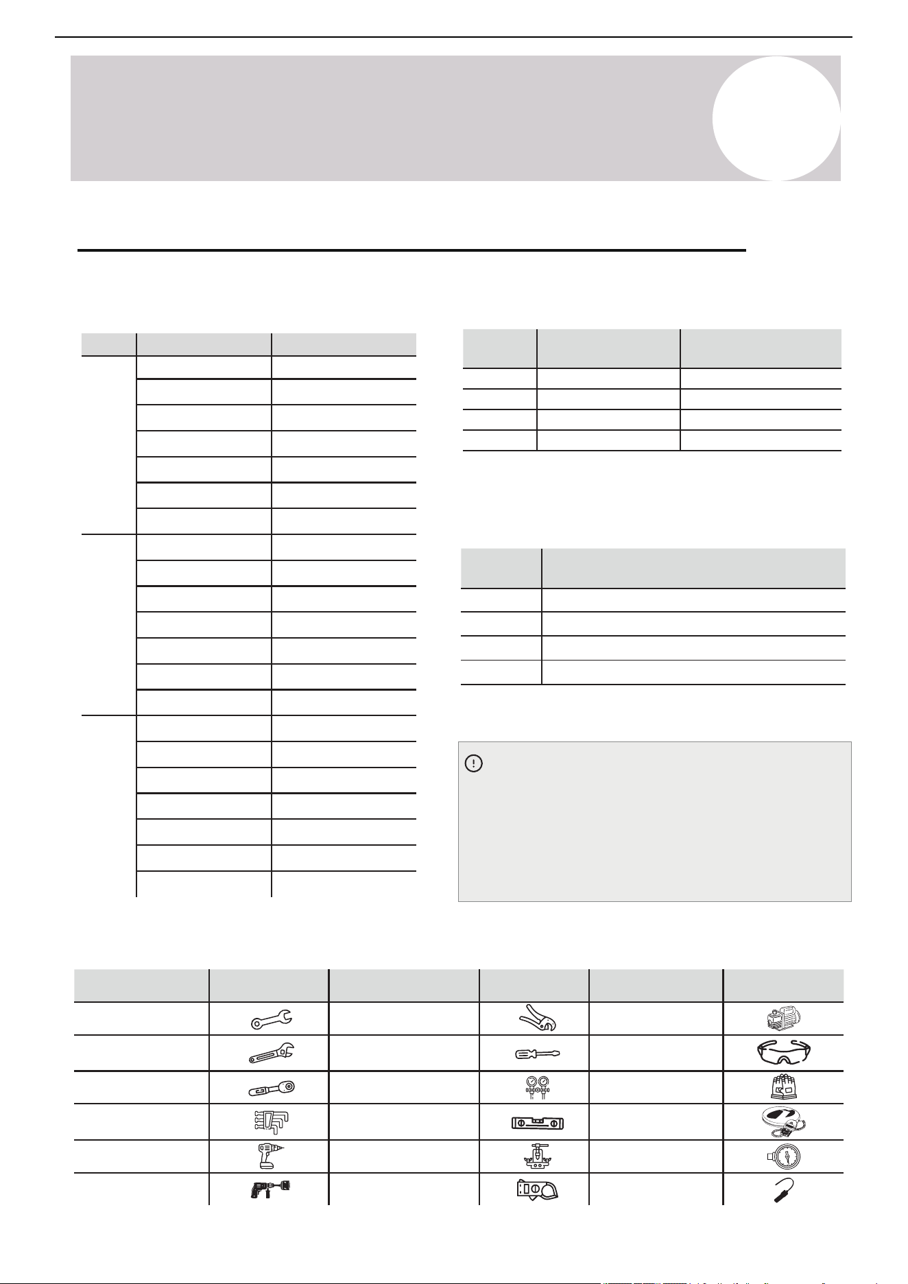
Page 30
Safety
Information
6
Considerations for A2L Refrigerants
Important Considerations:
1. The air conditioner must be installed and
serviced by qualified personnel. Installation
must comply with all instructions set forth
herein as well as all local regulations.
2. Caution when handling combustible
refrigerants – Improper or careless handling may
cause serious injury or damage to property.
3. A leak test must be conducted after installation
is completed to ensure system integrity.
4. Safety inspections are mandatory before
performing maintenance or repairs on air
conditioners using combustible refrigerants to
minimize fire risk.
5. The system must be operated under controlled
conditions to reduce the risk of combustible gas
or vapor hazards during operation.
6. The total weight of refrigerant charge and
minimum room area requirements for air
conditioners must comply with the specifications
outlined in Tables GG.1 and GG.2.
Maximum Refrigerant Charge and Required
Minimum Floor Area: The maximum charge is
determined by the following equations:
m
1
= (6m
3
) x LFL, m
2
= (52m
3
) x LFL, m
3
= (260m
3
) x LFL
Where LFL is the Lower Flammable Limit in kg/m³.
For R454-B refrigerant, LFL = 0.303 kg/m³.
For Appliances with a Charge Amount m
1
< M = m
2
:
The maximum refrigerant charge in a room must
comply with: M
max
= 2.5 x (LFL)
5/4
x h
0
x A
1/2
This value must not exceed: M
max
= SF x LFL x h
0
x A
(Refer to GG.3DV for specific factors and application.)
(If Applicable) Charging Protocol for A2L Refrigerants
Minimum Floor Area Requirement: The
required minimum floor area A
min
for an
appliance with a refrigerant charge M
c
(kg)
must be calculated as follows:
A
min
= [M
c
/(2.5 x LFL
5/4
x h
0
]
2
However, Amin must not be less than:
A
min
= M
c
/(SF x LFL x h
0
); SF=0.5
(Refer to GG.4DV for specific values/factors.)
Where Category = R454-B, LFL = 0.303 kg/m
3
Table GG.1 - Maximum Charge (kg)
(6’0”)
(Installed
Height)
(Installed
Height)
(Installed
Height)
(43 ft
2
)
(38.5 oz)
(67.3 oz)
1.09
1.91
(96.2 oz)2.73
(138.2 oz)3.92
(159.6 oz)4.52
(195.5 oz)5.54
(252.3 oz)7.1 5
(53.44 oz)
(93.5 oz)
1.52
2.65
(133.6 oz)3.79
(191.9 oz)5.44
(221.6 oz)6.28
(271.4 oz)7.7
(350.4 oz)9.94
(59.8 oz)
(104.7 oz)
1.7
2.97
(149.6 oz)4.24
(215 oz)6.09
(248.2 oz)7.0 4
(304 oz)8.62
(392.5 oz)11.12
(75 ft
2
)
(107 ft
2
)
(161 ft
2
)
(215 ft
2
)
(322 ft
2
)
(538 ft
2
)
(43 ft
2
)
(75 ft
2
)
(107 ft
2
)
(161 ft
2
)
(215 ft
2
)
(322 ft
2
)
(538 ft
2
)
(43 ft
2
)
(75 ft
2
)
(107 ft
2
)
(161 ft
2
)
(215 ft
2
)
(322 ft
2
)
(538 ft
2
)
(8’2”)
(9’2”)
7
A2L Refrigerants
Suggested Tools:
Tool Tool Tool
Illustration Illustration Illustration
Standard wrench
Adjustable / Crescent
wrench
Torque wrench
Hex keys or Allen
wrenches
Drill & Drill bits
Hole saw
Pipe cutter
Screw drivers
(Phillips & Flathead)
Manifold gauge
Level
Flaring tool
Clamp-on amp meter
Vacuum pump
Safety glasses
Work gloves
Refrigerant scale
Micron gauge
Leak detector
Table GG.3DV - Maximum Charge (g) [lbs]
The calculated minimum allowable room area for all
capacities is as follows:
The standard factory refrigerant charge amount as
well as the maximum allowable charge are as follows:
Where category: R-454B, LFL = 0.303 kg/m
3
Table GG.2 - Minimum Room Area (m
2
)
h
0
(m)
Charge Limit (kg)
Min. Room Area (m
2
)
Model
(BTU)
Minimum Allowable Room Area
(Assumes 25 ft. lineset and 6 ft. install height)
Model
(BTU)
R-454B Refrigerant
(Standard Charge)
R-454B Refrigerant
(Maximum Charge)
(Installed
Height)
1.8
(6'0")
2.5
(8'2")
2.8
(9'2")
0.8 (28.2 oz)
0.95 (33.5 oz)
1.0 (35.3 oz)
1.3 (45.9 oz)
1.58 (55.7 oz)
1.8 (63.5 oz)
2.0 (70.5 oz)
0.8 (28.2 oz)
0.95 (33.5 oz)
1.0 (35.3 oz)
1.3 (45.9 oz)
1.58 (
55.7 oz)
1.8 (63.5 oz)
2.0 (70.5 oz)
0.8 (28.2 oz)
0.
95 (33.5 oz)
1.0
(35.3 oz)
1.3
(
45.9
oz)
1.58
(
55.7
oz)
1.8
(
63.5
oz)
2.0
(
70.5
oz)
2.93 (32 ft
2
)
3.48 (38 ft
2
)
3.67 (40 ft
2
)
4.77 (52 ft
2
)
5.79 (63 ft
2
)
6.6 (71 ft
2
)
7.33 (79 ft
2
)
2.11 (23 ft
2
)
2.51 (27 ft
2
)
2.64 (29 ft
2
)
3.43 (37 ft
2
)
4.17 (45 ft
2
)
4.75 (52 ft
2
)
5.28 (57 ft
2
)
1.89 (21 ft
2
)
2.24 (25 ft
2
)
2.36 (26 ft
2
)
3.06 (33 ft
2
)
3.72 (41 ft
2
)
4.24 (46 ft
2
)
4.71 (51 ft
2
)
9,000
12,000
18,000
24,000
950 g / 2.09 lbs
1000 g / 2.2 lbs
1300 g / 2.87 lbs
1580 g / 3.48 lbs
1025 g / 2.26 lbs
1075 g / 2.37 lbs
1375 g / 3.03 lbs
1655 g / 3.65 lbs
Determining Refrigerant Amount
Use the above figures when charging an empty
system. The proceeding pages will also inform the
reader in determining the additional refrigerant
charging amounts for adjusting the factory charge
when using non-standard piping length.
Table GG.4DV - Minimum Room Area (m
2
)
9,000
12,000
18,000
24,000
3.48 m
2
(38 ft
2
)
3.67 m
2
(40 ft
2
)
4.77 m
2
(52 ft
2
)
5.79 m
2
(63 ft
2
)
29
Air Conditioner Installation & User Manual
Charging Protocol for A2L Refrigerants - If Applicable (Continued)
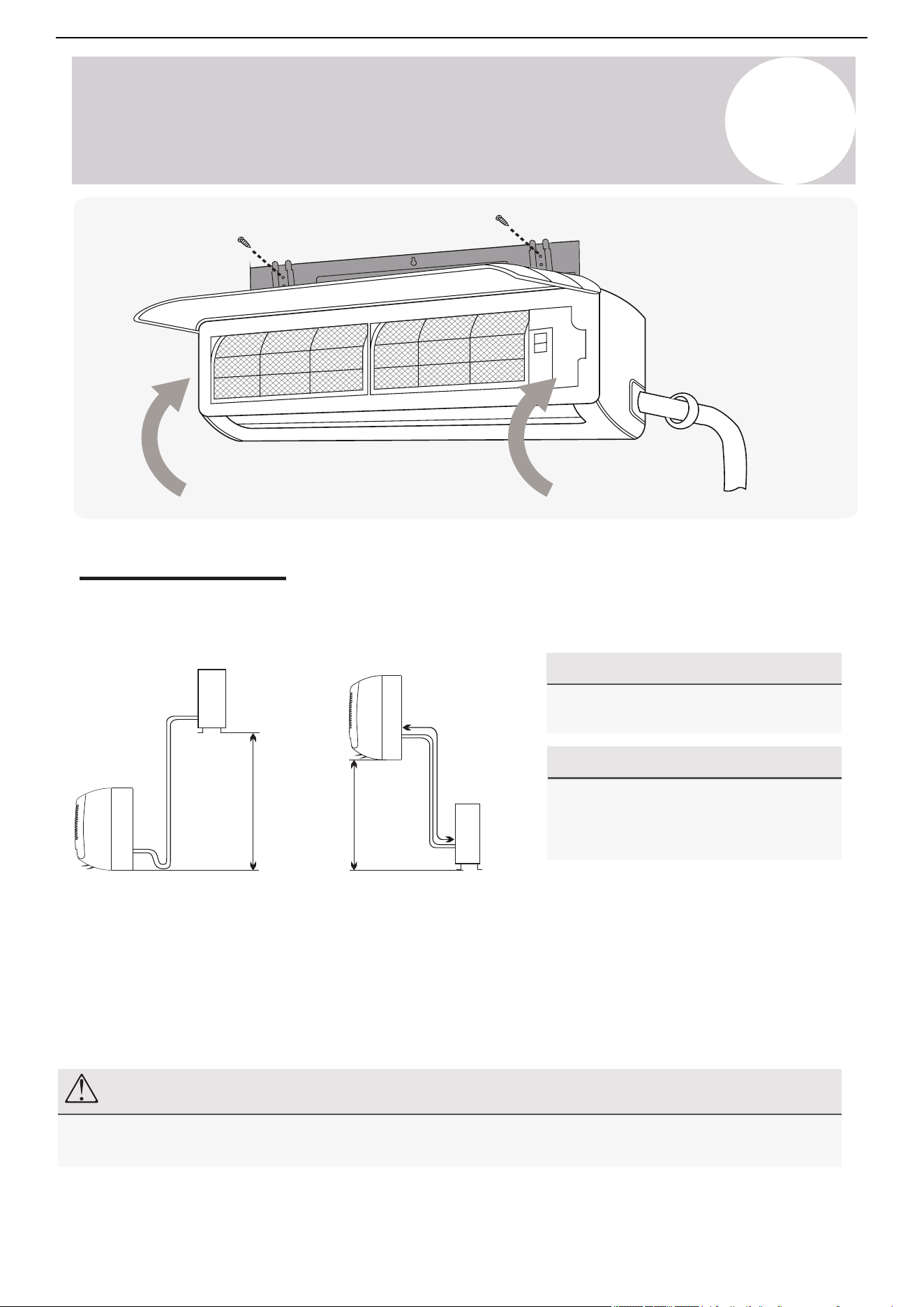
Page 33
Indoor Unit
Installation
7
Indoor Unit Installation Instructions
Indoor Unit Installation Location Selection
Follow the below best practices for selecting an optimal space for installation the indoor unit:
1.8-2.5 m (72-100 in) or more
Floor
Ceiling
10-15 cm (4-6in)
or more
10-15 cm (4-6 in)
or more
10-15 cm (4-6 in) or more
▪ DO NOT install the unit on a wall that is subject to vibrations.
▪ DO NOT install the system near sources of heat, steam, or flammable gases.
▪ DO NOT install the indoor unit in a location that is exposed to direct sunlight.
▪ DO ensure that the inlet and outlet vents are not obstructed. The system should be able to
output air all across the room.
▪ DO minimize the distance between the indoor and outdoor unit and install the unit in a place
where connecting the indoor and outdoor unit will be as simple as possible.
▪ DO install the unit on a strong wall and where it is easy to drain the condensate water.
▪ DO install the unit in a location where it will be easy to service the machine and perform any
necessary maintenance.
▪ DO obey the following tolerances depicted in the illustration below:
8
Indoor Unit
Installation Instructions
Note
Only qualified and experienced persons or companies may install, service, and repair refrigerant products. The
purchaser must ensure the system is installed carefully and correctly.
Installation Diagram
Before proceeding, it is important to consider the following height and length restrictions:
Outdoor Unit
Select the positions of both the indoor and outdoor units before starting the installation. Follow the minimum
clearance requirements for both the indoor and outdoor units, which can be found in the respective sections of
this manual. Follow all required clearances.
Install the indoor unit inside the room intended for air conditioning. Avoid corridors and communal areas.
Install the indoor unit so that its bottom is at least 72 inches (1.8 m) above the floor. Ensure adequate space
above the air handler for return airflow (4-6 inches, ideally 8 inches / 102-152 mm, ideally 203 mm).
30
Air Conditioner Installation & User Manual
For Systems of 9K and 12K BTU:
For Systems of 18K and 24K BTU:
• Follow the given constraints in the figures to
the left.
• The allowable height differential increases to
50 feet / 15 m.
• The allowable pipe length is 65 feet / 20 m.
Height differential
must be less
than 33 ft (10 m)
Outdoor Unit Indoor Unit
Indoor Unit
Pipe length
is 50 ft
(15 m) max
Pipe length
is 50 ft
(15 m) max
Height differential
must be less
than 33 ft (10 m)
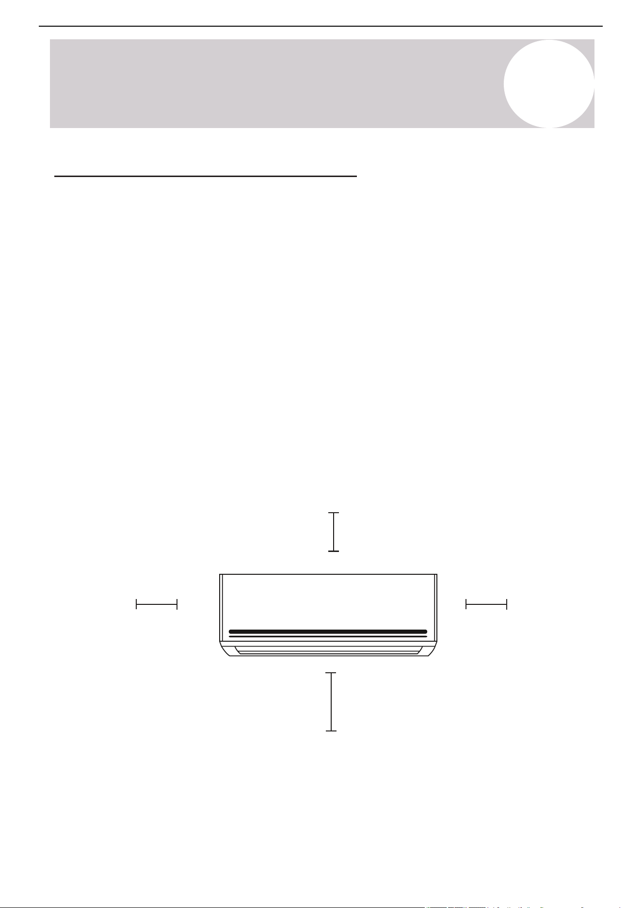
Page 32
Indoor Unit
Installation
7
Indoor Unit Installation Instructions
Installation Diagram
Before proceeding, it is important to consider the following height and length restrictions:
Install the indoor unit inside the room to be air conditioned, avoiding corridors and communal areas.
Install the indoor unit at a height such that the bottom of the indoor unit is at least 72 inches above
the floor. Allow adequate space (4-6 inches, ideally 8 inches) above the air handler for return airflow.
Before starting the installation, decide on the position of both the indoor and outdoor units.
Take into account the minimum clearance requirements for both the indoor and outdoor units,
which can be found in their respective sections of this manual. Follow all required clearances.
Indoor Unit
Pipe length
is 50' max
Pipe length
is 50' max
Outdoor Unit
Outdoor Unit Indoor Unit
Height differential
must be less than 33 ft.
Height differential
must be less than 33 ft.
NOTE
Only persons and/or companies qualified and experienced in the installation, service, and repair of refrigerant
products should be permitted to do so. The purchaser must ensure the system is installed carefully and correctly.
For Systems of 18K and 24K BTU:
For Systems of 9K and 12K BTU:
• Follow the given constraints in the
figures to the left.
• The allowable height differential
increases to 50 ft.
• The allowable pipe length is 65 ft.
8
Indoor Unit
Installation Instructions
31
Air Conditioner Installation & User Manual
Follow these best practices for selecting an optimal space for installation of the indoor unit:
Ceiling
4-6 in
(102-152 mm)
or more
Indoor Unit Installation Location Selection
• Do not install the unit on a wall that is subject to vibrations.
• Do not install the system near sources of heat, steam, or flammable gases.
• Do not install the indoor unit in a location that is exposed to direct sunlight.
• Ensure that the inlet and outlet vents are not obstructed. The system should be able to output air all across
the room.
• Minimize the distance between the indoor and outdoor units. Install the unit in a location where connecting
the indoor and outdoor units will be as simple as possible.
• Install the unit on a strong wall and where it is easy to drain the condensate water.
• Install the unit in a location where it will be easy to service the product and perform any necessary
maintenance.
• Obey the following tolerances depicted in the illustration below:
Floor
72-100 in (1.8-2.5 m) or more
4-6 in
(102-152 mm)
or more
4-6 in
(102-152 mm) or more
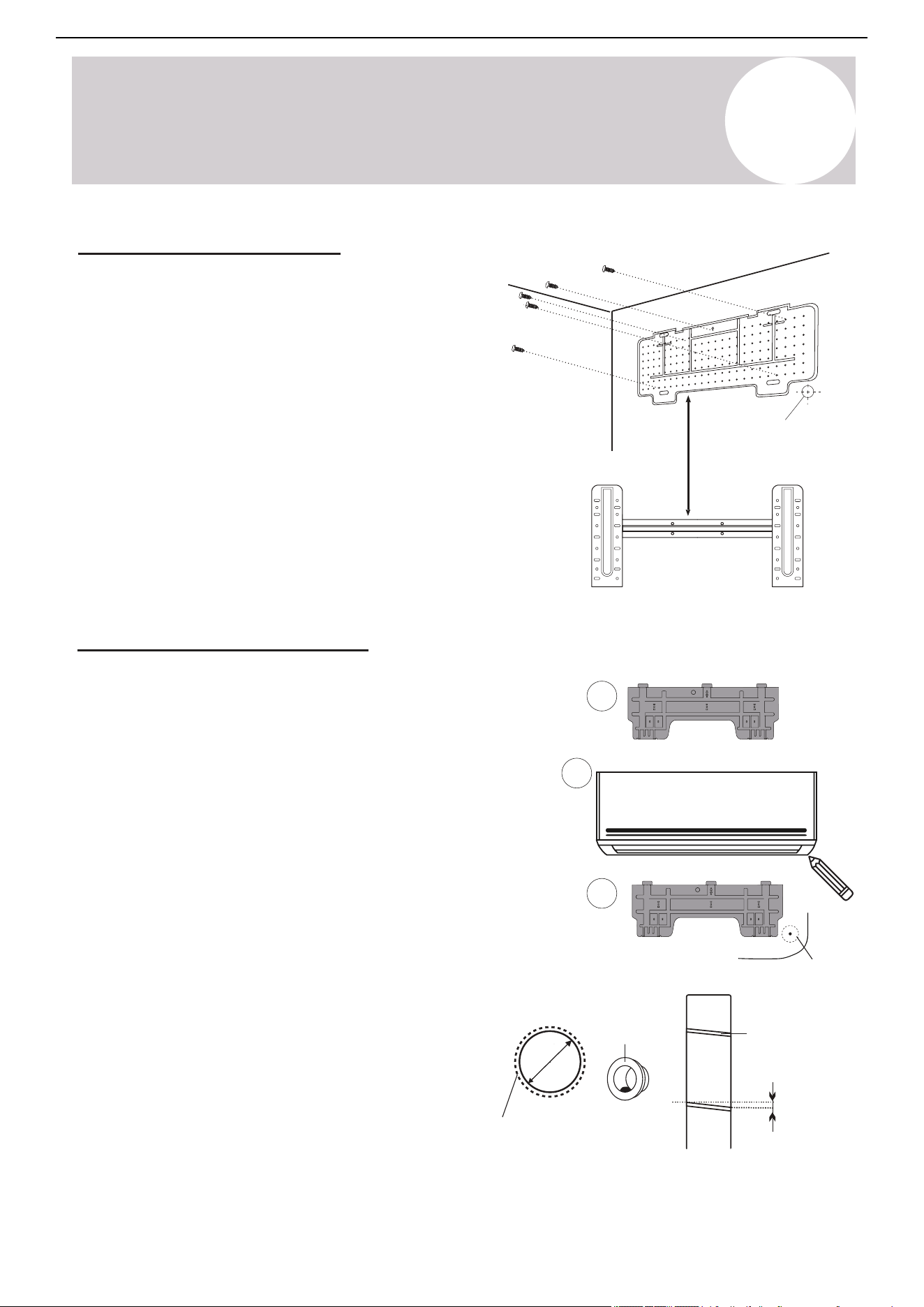
Page 35
Indoor Unit
Installation
7
Indoor Unit Installation Instructions
Electrical Connections - Indoor Unit
BEFORE PERFORMING ELECTRICAL WORK, READ THESE REGULATIONS
WARNING:
BEFORE PERFORMING ANY ELECTRICAL OR WIRING WORK, TURN OFF THE
MAIN POWER TO THE SYSTEM. NOTE MULTIPLE POWER SOURCES MAY EXIST.
Front Panel
Wiring Diagram
Terminal Block
Cover
All systems will include a wiring diagram affixed to the
indoor unit. See Page 38 for more details.
1. Lift up the front panel of the indoor unit.
2. Remove the cover as indicated in the illustration.
3. For the electrical wiring, consult the circuit diagram
affixed to the elecrical cover.
4. Connect the cables to the wiring terminal by following
the numbering. Use wire gauge suitable for the
electrical power input. (see name plate on the unit).
1. All wiring must comply with local and national electrical codes, and must be installed by a licensed
electrician.
2. All electrical connections must be made according to the Electrical Connection Diagram located
on the panels of the indoor and outdoor units.
3. If there is a serious safety issue with the power supply, stop work immediately. Explain your
reasoning to the client, and suspend all installation until the safety issue is properly resolved.
4. Power voltage should be within 90-110% of the range for the rated voltage. Insufficient power
supply can cause malfunction, electrical shock, or fire.
5. Connect power through fixed wiring, install a surge protector and a disconnect switch box, and a
dedicated circuit breaker with a capacity of 1.5 times the maximum current of the unit.
6. A properly rated HACR-type fuse or circuit breaker that disconnects all poles and that has a
contact separation of at least 1/8in (3mm) must be incorporated in the fixed wiring. The qualified
technician must use an approved circuit breaker or fuse.
7. Only connect the unit to an individual branch circuit. Do not connect another appliance to that
outlet. This equipment requires its own dedicated and protected circuit.
8. Make sure to properly ground the air conditioner. The use of a surge protector is recommended.
9. Every wire must be firmly connected. Loose wiring can cause the terminal to overheat, resulting in
product malfunction and possible fire.
10. Do not let wires touch or rest against refrigerant tubing, the compressor, or any moving parts
within the unit.
8
Indoor Unit
Installation Instructions
32
Air Conditioner Installation & User Manual
Ensure the mounting plate is firm and flat against the wall
1. Dislodge the mounting plate from the rear of the
indoor unit and place the mounting plate against the
wall where the system will hang. Use a level to
ensure that the plate is horizontally and vertically
level.
2. Drill 1-¼ inch (32 mm) deep holes for each screw
to enter. The locations are flexible but should be
spaced well.
3. Insert the plastic anchors into each of the holes.
4. Fix the mounting plate to the wall by using the
included tapping screws. Check that it is secured.
Install the Mounting Plate
Check pages 53-54 for Mounting Hole
Guidelines according to the bracket.
Note: The actual appearance of the mounting
plate may differ slightly, but the process is similar.
Drill the Wall Hole for Piping
1. With the mounting plate firmly affixed to the wall,
temporarily mount the indoor unit onto the mounting
plate in order to confirm the location of the wall hole
in the next steps.
2. Use a pencil to lightly trace the bottom corner of
the indoor unit, depending on which side exit the
piping will go through (page 34).
3. Take the inside unit off of the plate and make a
mark of where the hole will be (pages 53-54),
ensuring ample clearance between the tracing and
bracket.
4. Drill a 2-½~3-⅛ inch (63.5~79 mm) wall hole at a
slight downward angle using a core drill. Be careful to
avoid wires, plumbing, and other sensitive materials.
The bottom of the inside hole should be ¼ inch (6.35
mm) above the bottom of the outside hole.
Φ 2-½ in (65 mm)
Φ Up to 3-⅛ in (80 mm)
Indoors
Outdoors
(5-10 mm)
¼~⅜ in
1
2
3
If doing right side exit...
Small oblique angle
Φ 2-1/2 in
Wall sleeve cover
(Optional)
Wall sleeve
(Optional)
Wall hole
For bigger linesets or according to
the wall liner used, a larger wall
hole size up to 3-⅛ inch (79 mm)
can be made.
Φ 2-½~3-⅛ in
(Depending on the lineset)
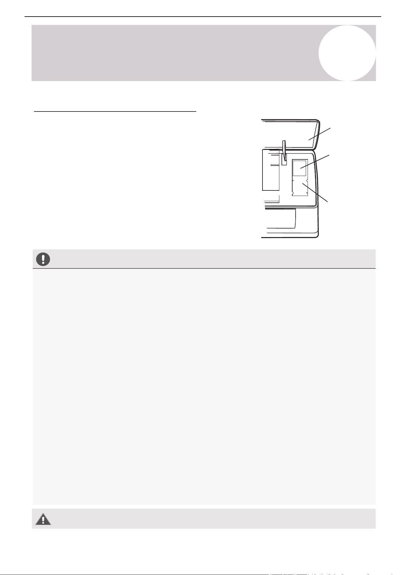
Page 34
Indoor Unit
Installation
7
Indoor Unit Installation Instructions
Installation of the Mounting Plate
Drilling the Wall Hole for Piping
Indoors Outdoors
(5-10 mm)
1/4”~3/8”
1
2
3
If doing right side exit...
Ensure the mounting plate is firm and flat against wall
Small Oblique Angle
Φ 2-1/2” (65mm)
Φ (Up to 3-1/8”/80 mm)
Φ 2-1/2”~3-1/8”
(depending on lineset)
Φ 2-1/2”
1. Dislodge the mounting plate from the rear of the
indoor unit and place the mounting plate against
the wall where the system will hang that fulfills the
constraints on page 33. Use a level to ensure that
the plate is horizontally and vertically level.
2. Drill 1-1/4” deep holes for each screw to enter. The
locations are flexible but should be spaced well.
3. Insert the plastic anchors into each of the holes.
4. Fix the mounting plate to the wall by using the
included tapping screws. Check that it is secured.
Note: The actual appearance of the mounting plate
may differ slightly but the process is similar.
CHECK PAGES 54-55 FOR MOUNTING HOLE
GUIDELINES ACCORDING TO THE BRACKET.
1. With the mounting plate firmly affixed to the wall,
mount the indoor unit onto the mounting plate
temporarily in order to confirm the location of the
wall hole in the next steps.
2. Using a pencil, lightly trace the bottom corner of
the indoor unit, depending on which side exit the
piping will go through (see Page 36).
3. Take the inside unit off of the plate, and make a
mark of where the hole will be (PG. 54-55), to
ensure ample clearance between the tracing and
bracket.
4. Drill a 2-1/2”~3-1/8“ wall hole at a slight
downward angle using a core drill, being careful
to avoid wires, plumbing, and other sensitive
materials. The bottom of the inside hole should
be ~1/4” above the bottom of the outside hole.
Wall Sleeve Cover
(Optional)
Wall Hole
(For bigger linesets, or according
to wall liner used, a larger wall
hole size up to 3-1/8” can be made)
Wall Sleeve
(Optional)
8
Indoor Unit
Installation Instructions
Electrical Connections - Indoor Unit
Front panel
Wiring diagram
All systems will include a wiring diagram affixed to the
indoor unit.
1. Lift up the front panel of the indoor unit.
2. Remove the cover as indicated in the illustration.
3. For the electrical wiring, consult the circuit diagram affixed to
the electrical cover.
4. Connect the cables to the wiring terminal by following the
numbering. Use wire gauge suitable for the electrical power
input. See the nameplate on the unit.
Terminal
block cover
33
Air Conditioner Installation & User Manual
Before Performing Electrical Work, Read These Regulations
Warning:
Before performing any electrical or wiring work, turn off the main power to the
system. Note multiple power sources may exist.
1. All wiring must comply with local and national electrical codes and must be installed by a licensed
electrician.
2. All electrical connections must be made according to the Electrical Connection Diagram located on the
panels of the indoor and outdoor units.
3. If there is a serious safety issue with the power supply, stop work immediately. Explain the reasoning to the
client and suspend all installation until the safety issue is properly resolved.
4. Power voltage should be within 90-110% of the range for the rated voltage. Insufficient power supply can
cause malfunctions, electrical shocks, or fires.
5. Connect power through fixed wiring. Install a surge protector, disconnect switch box, and dedicated circuit
breaker with a capacity of 1.5 times the maximum current of the unit.
6. A properly-rated HACR-type fuse or circuit breaker that disconnects all poles must be incorporated in the
fixed wiring. The fuse or circuit breaker must ensure contact separation of at least ⅛ inch (3 mm). The
qualified technician must use an approved circuit breaker or fuse.
7. Only connect the unit to an individual branch circuit. Do not connect another appliance to that outlet. This
equipment requires its own dedicated and protected circuit.
8. Make sure to properly ground the air conditioner. The use of a surge protector is recommended.
9. Every wire must be firmly connected. Loose wiring can cause the terminal to overheat, resulting in product
malfunction and possible fire.
10. Do not let wires touch or rest against the compressor, refrigerant tubing, or any moving parts within the
unit.
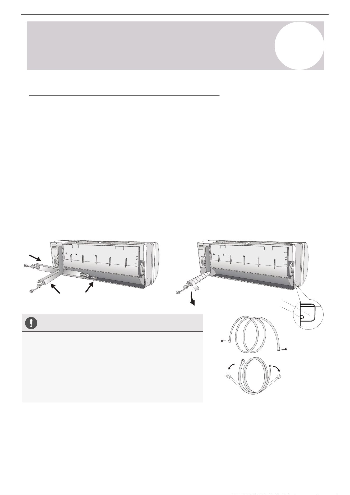
8
Indoor Unit
Installation Instructions
34
Air Conditioner Installation & User Manual
3
2
1
Downward
inclination
Caution
Yes
No
Piping outlet
Cable outlet
(Optional - If Needed)
Unwind the coil gently against a flat
surface, rather than pulling at the ends.
• Do not remove the seal caps from the pipe ends until it is time
to connect it, avoiding contaminants from entering.
• If the pipe is bent/pulled too often, it will become stiff. Don't
bend the pipe more than three times at one point. Be
extremely careful not to kink any piping.
• When extending the coiled copper pipes, straighten them by
unwinding gently, as shown in the picture.
Prepare the Refrigerant Piping of the Indoor Unit
The piping "pigtails" pre-attached to the indoor unit can be run in three different ways as shown in the illustration.
Decide which type of configuration is most suitable before continuing.
By default, it is routed for a left side exit as shown in option 1. This method can either use the left side knockout
for a side exit or a wall hole can be drilled on the left side of the unit's rear.
Routing it straight through the back of the system (option 2) will facilitate the connections to the copper pipe
extensions to be made outside. This is recommended to simplify the process.
Option 3 is a right side exit, but it is not recommended as it involves a 180° bend of the piping, which increases
the risk of kinking or collapsing the lines dramatically. Bend slowly and cautiously.
If a side-exit is chosen, there are knock-out panels on either side of the unit that can be cut along the groove to
provide a notch for the pipe to exit from. Use a suitable cutter to do this.
For the method chosen, run the piping in the direction of the wall hole. Bind the copper pipes, drain pipe, and
power cables together with tape. Keep the drain pipe at the bottom so that the water can flow freely. Ensure that
the bundle is exiting at a continuous downward pitch.
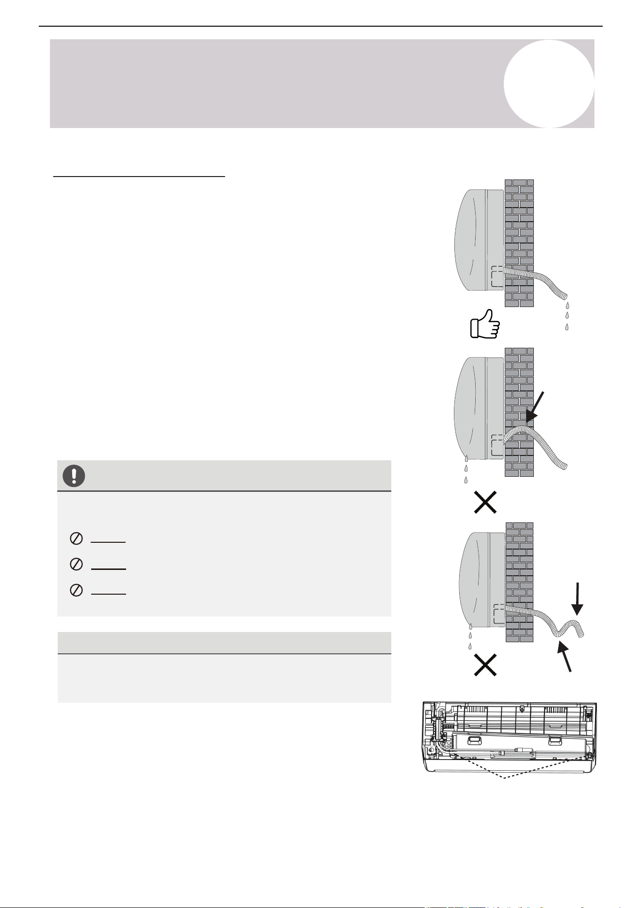
8
Indoor Unit
Installation Instructions
Yes
No
No
Drainage ports
35
Air Conditioner Installation & User Manual
Connect the Drain Hose
By default, the drain hose is attached to the left-hand side of unit
(”left” when facing the back of the unit). However, it can also be
attached to the right-hand side.
1. To ensure proper drainage, attach the drain hose on the same
side that the refrigerant piping exits the unit from.
2. Attach any drain hose extensions (sold separately) to the end of
the drain hose.
3. Wrap the connection point of the drain hose firmly with Teflon
tape to create a good seal and prevent leaks.
4. For the portion of the drain hose that will remain indoors, wrap it
with foam pipe insulation to prevent condensation.
5. Remove the air filter and pour a small amount of water into the
drain pan to make sure that water flows away from the unit
smoothly.
Note on Drain Hose Placement
Dual Drain Hole Locations Exist
The indoor unit has two drain connections on the left and right
sides. Either one can be utilized. One side will have a hose
connected, while the other is plugged.
Make sure to arrange the drain hose according to the illustrations.
Do Not kink the drain hose.
Do Not create a water trap (siphon).
Do Not put the end of the drain hose in water or in a
container that will collect water.
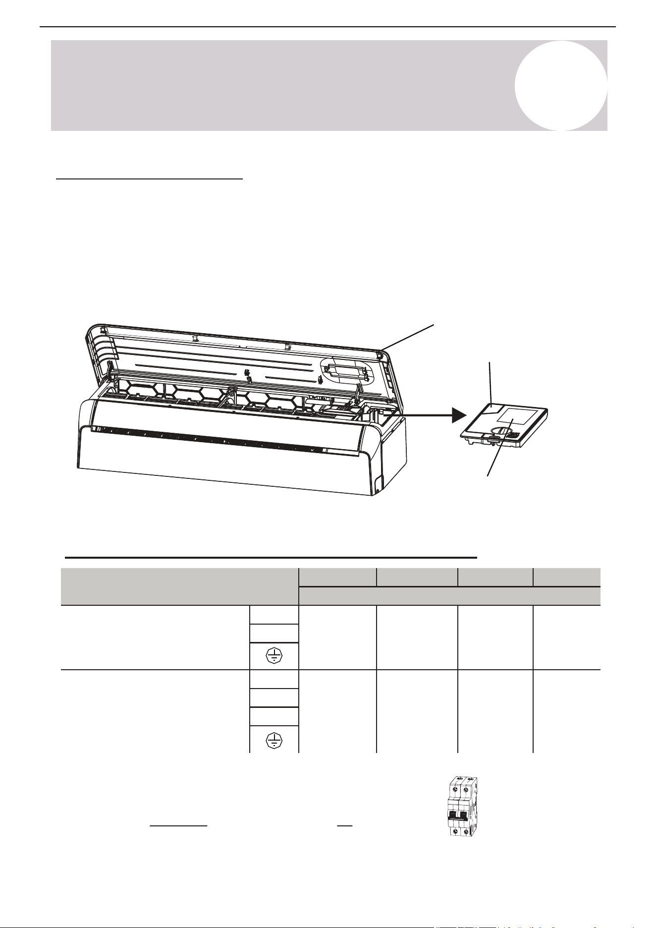
Pioneer WYT-25 Series Mini Split
9K 12K 18K
24K
Sectional Area (AWG)
Power Supply Cable
L2
14 AWG 12 AWG 10 AWG
10 AWG
L1
Connection Cable for
Communication Between
Indoor & Outdoor Units
3(L)
16 AWG
16 AWG 16 AWG
16 AWG
2(N)
1(S)
Front panel
Wiring diagram
Serial number
8
Indoor Unit
Installation Instructions
Connect the Signal Cable
Color selection does not matter as much as matching number to number does. Consult the diagram affixed to
the indoor and outdoor unit respectively for specific wiring instructions. There are 3 terminals (1, 2, 3) and
ground (G). Do not mix up the wires between each ends. It is vital that the colors between the indoor and
outdoor unit match for each terminal. A simplified wiring diagram is included in the Appendix section of this
manual. On the indoor unit, the wiring diagram is located underneath the front panel as shown below:
• 230V require a double-pole breaker (tandem-type will not work)
Consult the nameplate on the system for detailed electrical
specifications. Confirm wiring on page 40. Above power wire sizes
assume largest allowable fuse.
36
Air Conditioner Installation & User Manual
Cable Wire Specifications (For Common Configurations)
Double-Pole
230V Breaker
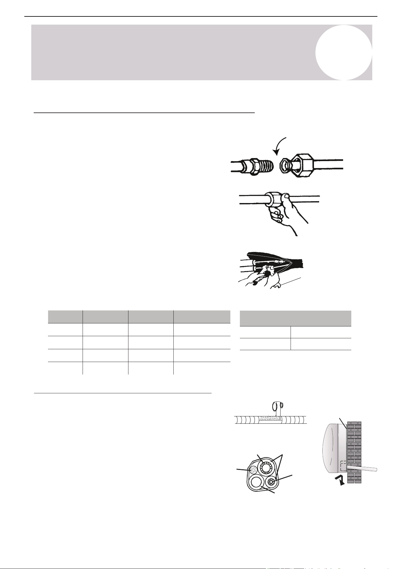
8
Indoor Unit
Installation Instructions
37
Air Conditioner Installation & User Manual
Connect the Refrigerant Piping to the Indoor Unit
Torque wrench
Tightening Torque for Protection Caps & Flange Connection
Service Port Nut
Protection Caps
[7 - 9] (5-7)
[25 - 30] (18-22)
Refrigerant
pipe
Refrigerant
pipe
Insulation
sleeve
Connection
cable
Condensed water drain pipe
(Always at the bottom)
Covered by vinyl tape
Mounting plate
Apply leak-prevention
gels or gaskets to all
mating surfaces
Φ
Once the copper piping kit is unwound, refer to the below
instructions to proceed:
1. Bring the ends of both the copper line and the indoor unit
line together. Align the centers of the pipes that will be
connected.
2. Remove the indoor unit piping cap and check that no
debris is inside. Some gas may be heard escaping, but it is
dry nitrogen to keep lines clean.
3. Use any leak guard and/or flare sealers on the flares of the
piping if available. Attach the flare nut and tighten as much as
possible by hand. Torque correctly to the specifications found
in the table below using two wrenches. Repeat the process
for the other copper line.
Wrap the Lines & Mount the Indoor Unit
For mounting the indoor unit, follow these steps:
1. Arrange the pipes, cables, and drain hose correctly.
2. Lag the pipe joints with insulation material and
secure them with vinyl tape as depicted in the figure.
3. Run the bound bundle through the wall hole and
mount the indoor unit securely onto the mounting plate.
Press/push the lower part of the indoor unit so it clicks
onto the mounting plate.
Tightening Torque
[N x m] (ft-lbf)
Pipe
Diameter
Tightening Torque
[N x m]
Tightening Torque
[ft-lbf]
Corresponding Stress
(Using a 20 cm wrench)
Wrist Strength
Arm Strength
Arm Strength
Arm Strength
11 - 15
23 - 26
33 - 37
44 - 48
15 - 20
31 - 35
45 - 50
60 - 65
1/4"
(6.35 mm)
Φ
3/8"
(9.52 mm)
Φ
1/2"
(12 mm)
Φ
5/8"
(15.88 mm)
Hand-tighten at
first to avoid risk of
cross-threading
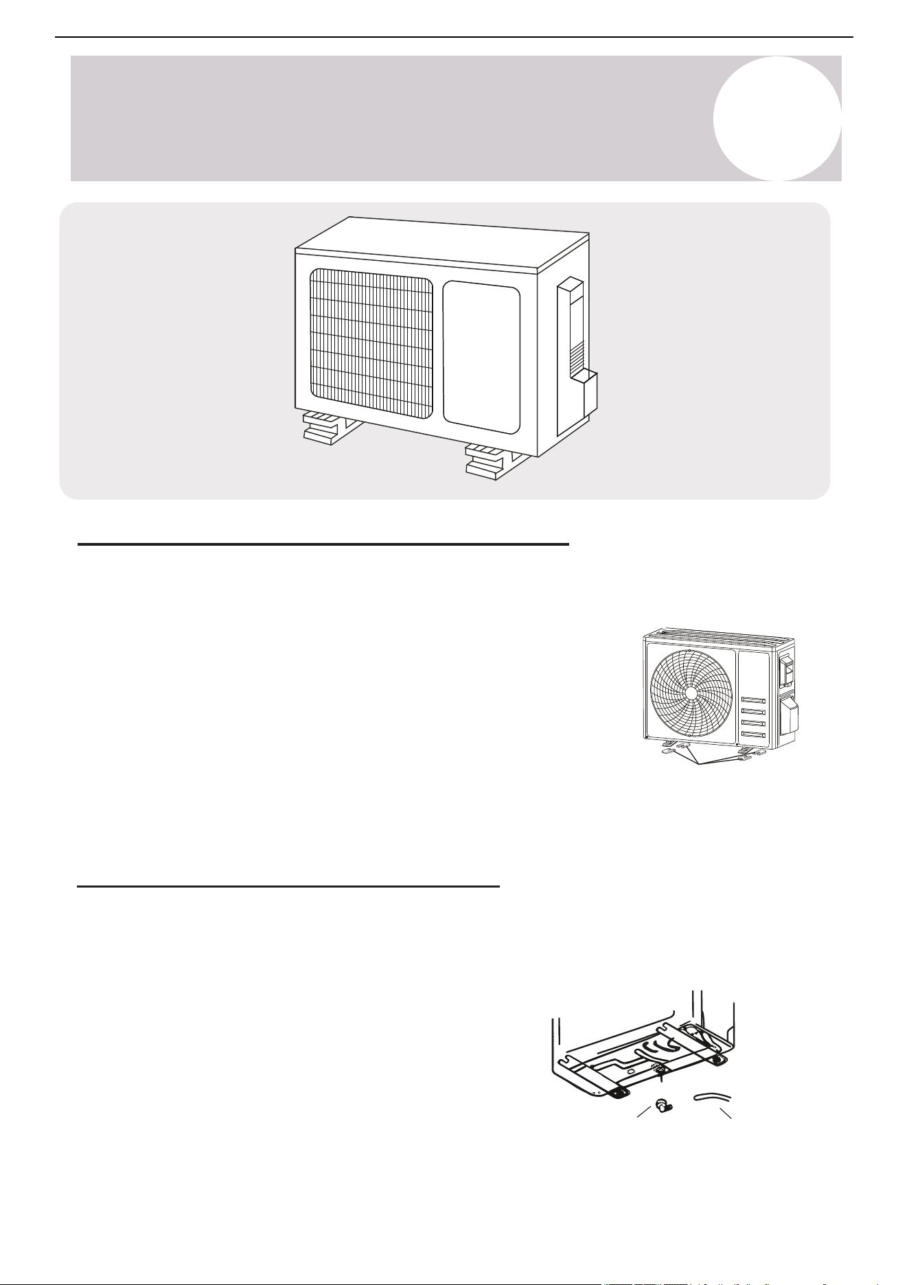
9
Outdoor Unit
Installation Instructions
38
Air Conditioner Installation & User Manual
Drain pipe
*Disregard if
slab-mounting
Drain port
Install 4 rubber pads (Optional)
Outdoor Unit Condensate Water Drainage
Use the drain joint and drain pipe included with the system to direct away the condensate water and ice formed
in the outdoor unit during Heating mode. This is optional and only needed if the default configuration of the
water drainage out from the port on the bottom side is not desired.
1. Fasten the drain port in the 1 inch (25 mm) port located in
the part of the unit depicted in the diagram.
2. Connect the drain port and drain pipe.
3. Ensure the condensate will drain to a suitable place.
Mount the Outdoor Unit to the Selected Location
Install the outdoor unit either on a pad or solid wall using suitable mounting brackets. Ensure it is fastened
securely. Follow the procedure below before connecting any pipes or cables:
• Decide the best position on the wall or ground and leave enough
space to be able to carry out maintenance easily. Anchoring
dimensions are provided on page 53.
• If wall mounting, fasten the supporting brackets to the wall using
hardware that is particularly suited for the type of wall. Use the
appropriate amount of hardware for the application.
• Install the unit following all national regulations.
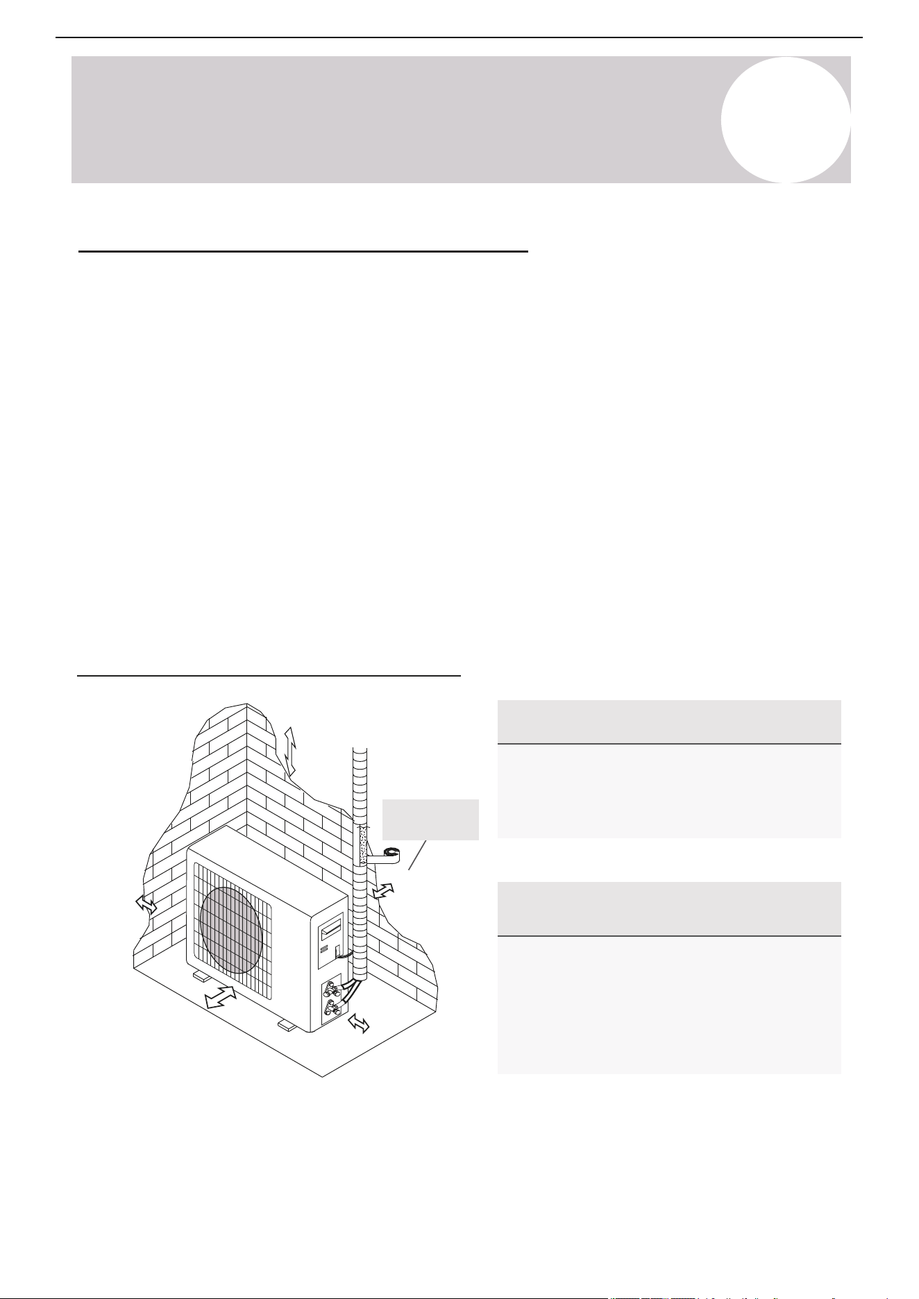
9
Outdoor Unit
Installation Instructions
39
Air Conditioner Installation & User Manual
Outdoor Unit Installation Location Selection
Follow the below best practices for selecting an optimal installation space of the indoor unit:
• Do not install the unit near sources of heat, steam, or flammable gases.
• Do not install the system in areas prone to extreme winds or dust.
• Do not install the outdoor unit in an area that has many individuals pass by.
• Select a location where the air discharge and operating sound level will not disturb others.
• Install the system in a shaded area or utilize a cover/sun protection that will not interfere with air flow. This will
also protect the system from heavy rain or snow.
• Install the unit in a safe and sturdy location.
• Install rubber vibration absorbers if the system can induce vibrations in any structure.
• Obey the following tolerances depicted in the illustration below to ensure air flow:
Minimum Required Installation Space
Special Considerations for
Extreme Weather Conditions
For Best Longevity & Performance in
Precipitation / Airflow / Salty Air
(4 in when using
wall brackets)
12 in (on slab)
305 mm
20 in
508 mm
79 in
2 m
12 in
305 mm
20 in
508 mm
If the unit is frequently exposed to heavy rain or snow:
Build a shelter above the unit to protect it from the rain or
snow. Be careful not to obstruct the air flow around the unit.
If the unit is frequently exposed to salty air (seaside
air): Use specifically approved anti-corrosion coating
sprays on the heat exchanger surface in order to resist
corrosion.
If the unit is exposed to heavy wind: Install the unit so
that the air outlet fan is at a 90° angle to the direction of the
wind. If needed, use wind baffles or build a barrier in front
of, but sufficiently away from, the unit to protect it from
extremely heavy winds.
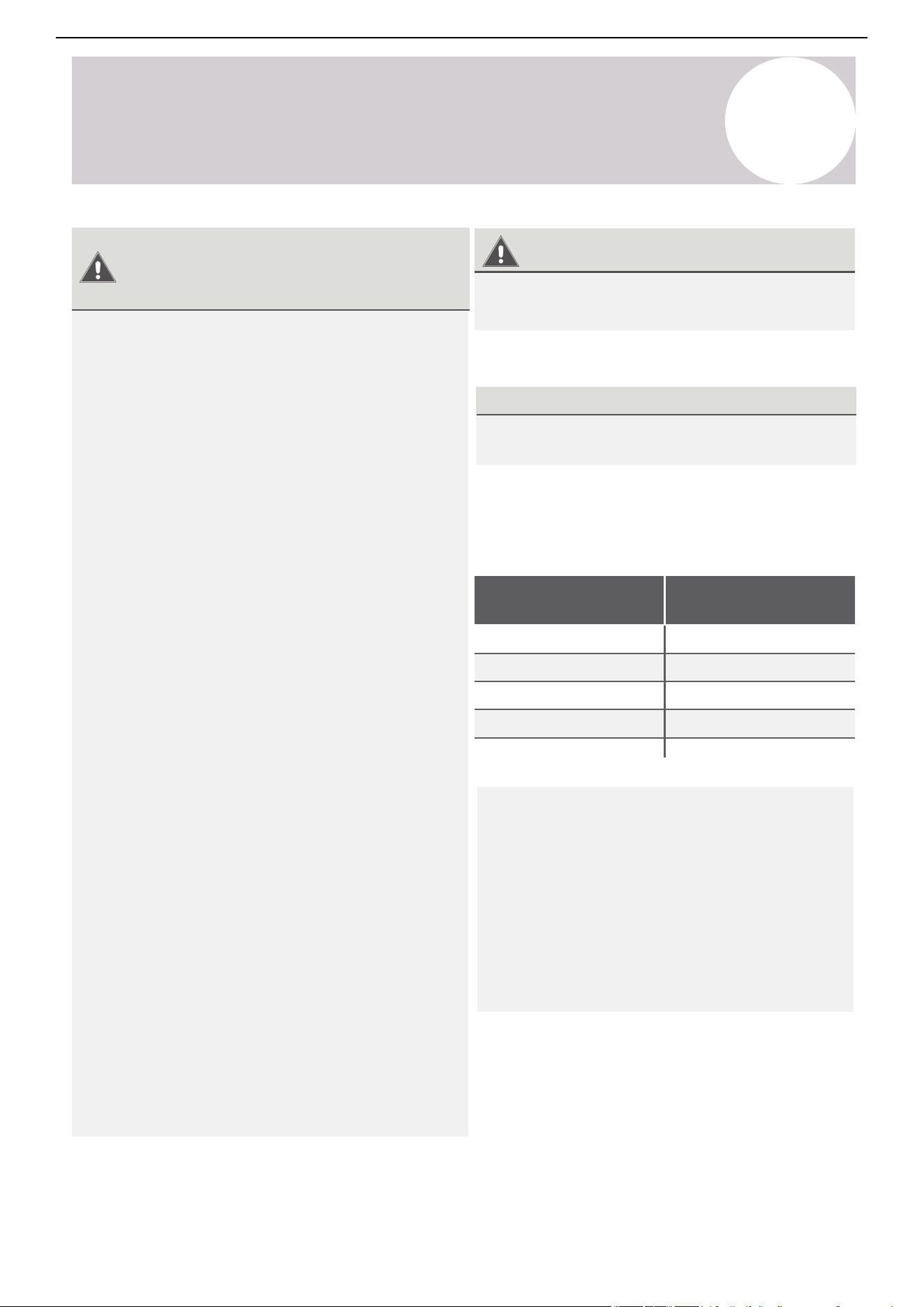
Page 43
Outdoor Unit
Installation
8
Outdoor Unit Installation Instructions
Power/Signal Electrical Wiring to the Outdoor Unit
On the outdoor unit, the wiring diagram is located in the inner side of the handle cover.
Cover
Outdoor Unit Wiring Diagram
is located on the inside of the
wire cover on the outdoor unit.
The outside unit’s terminal block is protected by
an electrical wiring cover on the side of the unit.
A comprehensive wiring diagram is printed on
the inside of the wiring cover.
1. Unscrew and remove the handle on the
right side plate of the outdoor unit.
2. Wire the system using the appropriate
gauge wire found on page 38/42 and the
wiring diagram found on the handle cover.
See page 55 for more details.
3. Use proper flexible rain-tight conduit with
appropriate size connectors.
4. Fasten the power connection wires into
place using the supplied wire clamps.
5. Check the wiring against the diagram to
ensure it is wired correctly. A proper
ground must be established.
6. Rescrew and reinstall the cover handle.
Outdoor Handle Cover
Wiring Diagram
Serial Number
9
Outdoor Unit
Installation Instructions
40
Air Conditioner Installation & User Manual
Warning
Use the Right Cable
Minimum Cross-Sectional Area of
Power & Signal Cables
North America
• Outdoor power cable: THHN or THWN
• Signal cable: TC-ER or better (AWG #16)
Before performing any electrical or wiring work, turn
off the main power source or sources to the system.
1. Prepare the cable for connection:
1. All wiring must comply with local and national
electrical codes and must be installed by a licensed
electrician.
2. All electrical connections must be made according to
the Electrical Connection Diagram located on the side
panels of the indoor and outdoor units.
3. If there is a serious safety issue with the power
supply, stop work immediately. Explain your reasoning
to the client and suspend the installation of the unit until
the safety issue is properly installed.
4. The power voltage should be within 90-110% of the
rated voltage range. Insufficient power supply can cause
electrical shocks or fires.
5. Connect the power through fixed wiring, install a
surge protector*, and disconnect the switch box. Use a
dedicated circuit breaker with a capacity of 1.5 times the
maximum current of the unit.
6. A properly-rated HACR-type fuse or circuit breaker
that disconnects all poles and has a contact separation
of at least ⅛ inch (3 mm) must be incorporated in the
fixed wiring. The qualified technician must use an
approved circuit breaker or switch.
7. Only connect the unit to a dedicated individual branch
circuit breaker. Do not connect another appliance to that
same circuit.
8. Be sure to properly ground the air conditioner.
9. Every wire must be firmly connected. Loose wiring
can cause the terminal to overheat, resulting in product
malfunction and possible fire.
10. Do not let wires touch or rest against the refrigerant
tubing, compressor, or any other moving parts within the
unit.
*optional, highly recommended.
Read These Regulations Before
Performing Any Electrical Work
Circuit Breaker Size (A) Wire Size (AWG)
10 18
13 16
15 14
20 12
30 10
Using wire strippers, strip the rubber jacket from
both ends of the cable to reveal about 1.5 inch (40
mm) of the wires inside. Strip the insulation from the
ends of the wires. Using a wire crimper, crimp u-lugs
on the ends of the wires. Note: Some cables come
with preinstalled u-lugs from the factory.
Indoor Unit Terminal Position #1 connects to
Outdoor Unit Terminal Position #1
Indoor Unit Terminal Position #2 connects to
Outdoor Unit Terminal Position #2
Indoor Unit Terminal Position #3 connects to
Outdoor Unit Terminal Position #3
Indoor Unit Terminal Position "Ground" connects to
the Outdoor Unit Grounding Lug.
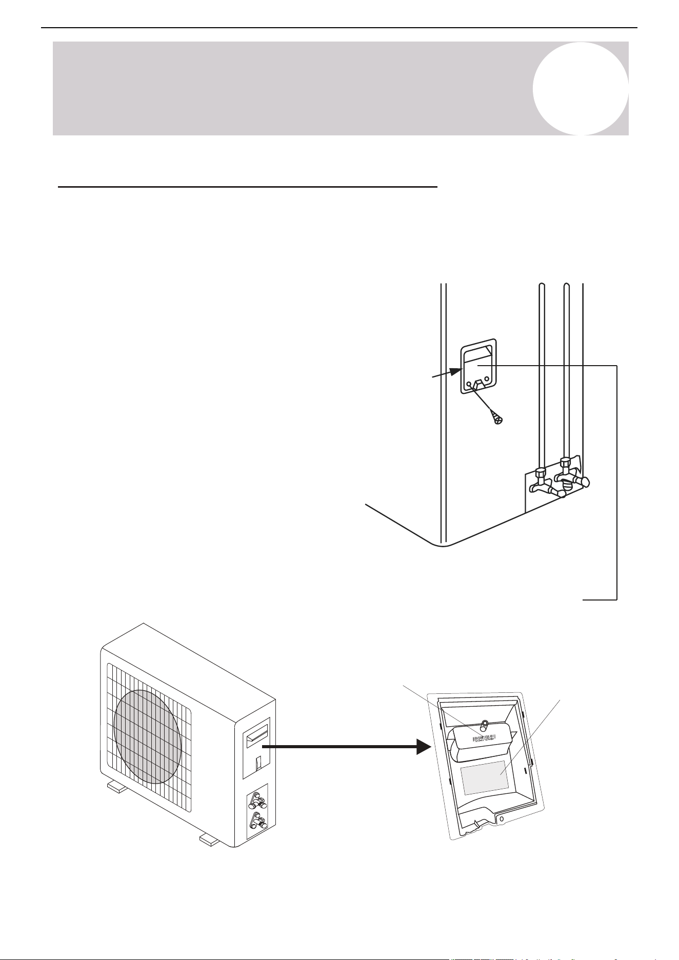
9
Outdoor Unit
Installation Instructions
41
Air Conditioner Installation & User Manual
Cover
The outdoor unit wiring diagram is
located on the inside of the wire cover
on the outdoor unit.
Outdoor handle cover
Wiring diagram
Serial number
Power/Signal Electrical Wiring to the Outdoor Unit
On the outdoor unit, the wiring diagram is located in the inner side of the handle cover.
An electrical wiring cover on the side of the unit protects the outside unit's terminal block. A comprehensive
wiring diagram is printed on the inside of the wiring cover.
1. Unscrew and remove the handle on the right side plate
of the outdoor unit.
2. Wire the system using the appropriate gauge wire found
on page 36/40 and the wiring diagram found on the handle
cover.
3. Use a proper flexible rain-tight conduit with appropriate
size connectors.
4. Fasten the power connection wires into place using the
supplied wire clamps.
5. Check the wiring against the diagram to ensure it is
wired correctly. A proper ground connection must be
established.
6. Rescrew and reinstall the cover handle.
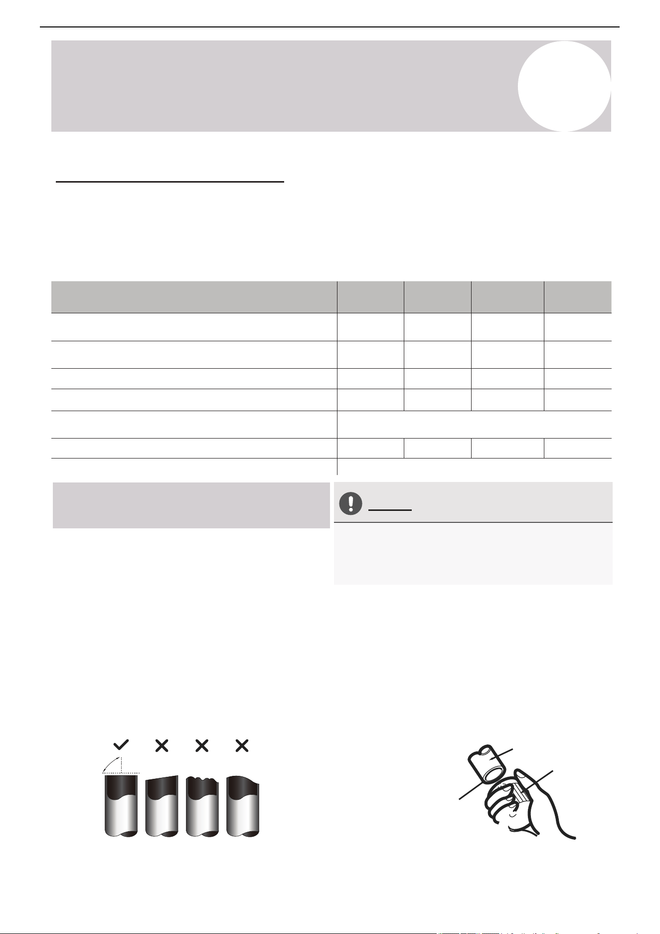
Page 45
Outdoor Unit
Installation
8
Outdoor Unit Installation Instructions
Step 3: Flare pipe ends
Proper flaring is essential to achieve an airtight
seal.
Flare Nut
Copper Pipe
1.
After removing burrs from cut pipe, seal
the ends with PVC tape to prevent foreign
materials from entering the pipe.
2.
Sheath the pipe with insulating material.
3.
Place flare nuts on both ends of pipe. Make
sure they are facing the correct direction,
because they cannot be put on or have
their direction chaged after flaring.
4.
Remove PVC tape from ends of pipe when
ready to perform flaring work.
5.
Clamp flare form on the end of the pipe.
The end of the pipe must extend beyond the
edge of the flare form in accordance with the
dimensions shown in the following table:
PIPING EXTENSION BEYOND FLARE FORM
A (mm)Outer Diameter of
Pipe (mm)
Min. Max.
Ø 6.35 (Ø 1/4”) 1.3 (0.05”) 0.7 (0.03”)
1.0 (0.04”) 1.6 (0.06”)Ø 9.52 (Ø 3/8”)
1.0 (0.04”) 1.8 (0.07”)Ø 12.7 (Ø 1/2”)
Ø 16 (Ø 5/8”)
Ø 19 (Ø 3/4”)
2.0 (0.08”) 2.2 (0.09”)
2.0 (0.08”) 2.4 (0.1”)
Flare Form
Pipe
A
6.
Place flaring tool onto the form.
7.
Turn the handle of the flaring tool
clockwise until the pipe is fully flared.
8.
Remove the flaring tool and flare form, then
inspect the end of the pipe for cracks and
successful, even flaring.
If provided by the supplier, apply leak
guard material on all flared mating surfaces.
Do NOT use any plumbing or putty sealants.
Step 4: Connect pipes
When connecting refrigerant pipes, be careful
not to use excessive torque, or to deform the
piping in any way. One should first connect the
low-pressure pipe, then the high-pressure pipe.
Connection Pipes
Flare Nuts
9
Outdoor Unit
Installation Instructions
Connect the Refrigerant Piping
The length of the refrigerant piping will affect the performance and energy efficiency of the unit. Nominal
efficiency is tested on units with a pipe length of 16 feet (4.9 m). Factory precharge is sufficient for supporting
up to 25 feet (7.6 m) of connected lineset. Piping should not be shorter than 10 feet (3 m) in length. Refer to the
table below for specifications on the maximum length and drop height of the piping. If the factory precharge is
modified, make a note of the charge modification amount on page 61.
Liquid Pipe Diameter
Gas Pipe Diameter
Max. Length of Pipe with Standard Charge
Max. Distance Between Indoor and Outdoor Unit
Adjustment Refrigerant Charge
(For each additional foot after 25 ft.)
Max. Difference in Level Between Indoor and Outdoor Unit
Pioneer WYT-25 Series Mini Split
Model / Capacity (BTU/h)
Type of Refrigerant
9K BTU 12K BTU 18K BTU 24K BTU
Φ
1/4"
(6.35 mm)
Φ
1/4"
(6.35 mm)
Φ
1/4"
(6.35 mm)
Φ
1/4"
(6.35 mm)
Φ
3/8"
(9.52 mm)
Φ
3/8"
(9.52 mm)
Φ
1/2"
(12 mm)
Φ
5/8"
(15.88 mm)
25 ft / 7.6 m 25 ft / 7.6 m 25 ft / 7.6 m 25 ft / 7.6 m
50 ft / 15 m 65 ft / 20 m
65 ft / 20 m
33 ft / 10 m 33 ft / 10 m 50 ft / 15 m
50 ft / 15 m
50 ft / 20 m
R-454B
0.11oz/ft
10g/m
42
Air Conditioner Installation & User Manual
Connection Instructions –
Refrigerant Piping
Oblique Rough Warped
90°
Pipe
Reamer
Point down
Ensure no shavings
can fall inside of tubes
*Most standard linesets are pre-flared. In some cases, modifications are needed.
Do Not Deform Pipe While Cutting
Step 1: Cut Pipes (if cutting the
lineset shorter)*
When preparing refrigerant pipes, take care to cut and
flare them properly. This will ensure efficient operation
and minimize the need for future maintenance.
1. Measure the distance between the indoor and
outdoor units.
2. Use a rolling blade type pipe cutter to cut the pipe a
little longer than the measured distance.
3. Make sure that the pipe is cut at a perfect 90° angle.
Refer below for bad cut examples.
Be careful not to damage, kink, or deform the pipe
while cutting. This will drastically reduce the efficiency
and capacity of the unit and may cause internal
damage.
Step 2: Remove Any Burrs Carefully
Burrs can affect the air-tight seal of the refrigerant
piping connection. They must be completely removed.
Follow these steps for proper deburring.
1. Hold the pipe at a downward angle to prevent burrs
from falling into the pipe.
2. Use a reamer or deburring tool to remove all burrs
from the cut section of the pipe.
Page 44
Outdoor Unit
Installation
8
Outdoor Unit Installation Instructions
Connection of the Refrigerant Piping
Connection Instructions –
Refrigerant Piping
Step 1: Cut pipes (If cutting lineset shorter)*
1. Measure the distance between the indoor and
outdoor units.
2. Using a rolling blade type pipe cutter, cut the pipe
a little longer than the measured distance.
3. Make sure that the pipe is cut at a perfect 90°
angle. Refer below for bad cut examples:
Oblique Rough Warped
90°
DO NOT DEFORM PIPE
WHILE CUTTING
Be extra careful not to damage, kink, or
deform the pipe while cutting. This will
drastically reduce the efficiency and capacity
of the unit and may cause internal damage.
Step 2: Remove any burrs carefully.
Burrs can affect the air-tight seal of refrigerant
piping connection. They must be completely
removed. Follow these steps for proper deburring:
1.
Hold the pipe at a downward angle to
prevent burrs from falling into the pipe.
2.
Using a reamer or deburring tool, remove
all burrs from the cut section of the pipe.
Pipe
Reamer
Point down
Ensures no shavings
can fall inside of tubes
The length of refrigerant piping will affect the performance and energy efficiency of the unit.
Nominal efficiency is tested on units with a pipe length of 16 ft. Factory precharge is sufficient
for supporting up to 25 ft of connected lineset. Piping should not be shorter than 10 ft in length.
Refer to the table below for specifications on the maximum length and drop height of piping.
If the factory precharge is modified, make a note of the charge modification amount on Page 59.
When preparing refrigerant pipes, take extra care
to cut and flare them properly. This will ensure
efficient operation and minimize the need for
future maintenance.
*Most standard linesets are pre-flared. In case modifications are needed.
Φ Φ Φ Φ
Φ Φ Φ Φ
9
Outdoor Unit
Installation Instructions
43
Air Conditioner Installation & User Manual
Flare nut
Copper pipe
Piping Extension Beyond Flare Form
A (inch/mm)
Outer Diameter of
Pipe (inch/mm)
Min.
Max.
Ø 1/4” (Ø 6.35)
0.05” (1.3)
0.03” (0.7)
0.04” (1.0)
0.06” (1.6)
0.07” (1.8)
0.08” (2.0)
0.09” (2.2)
0.1” (2.4)
Flare form
Pipe
A
Connection pipes
Flare nuts
Step 3: Flare Pipe Ends
Proper flaring is essential to achieve an airtight
seal.
1. After removing burrs from the cut pipe, seal the
ends with PVC tape to prevent foreign materials
from entering the pipe.
2. Sheath the pipe with insulating material.
3. Place flare nuts on both ends of the pipe. Make
sure they are facing the correct direction,
because they cannot have their direction changed
after flaring.
4. Remove the PVC tape from ends of the pipe
when preparing to perform flaring work.
5. Clamp the flare form on the end of the pipe. The
end of the pipe must extend beyond the edge of
the flare form in accordance with the dimensions
shown in the following table:
6. Place the flaring tool onto the form.
7. Turn the handle of the flaring tool clockwise until
the pipe is fully flared.
8. Remove the flaring tool and flare form, then
inspect the end of the pipe for cracks.
Step 4: Connect Pipes
When connecting the refrigerant pipes, be careful
not to use excessive torque or deform the piping in
any way. Begin by connecting the low-pressure
pipe, then the high-pressure pipe.
If provided by the supplier, apply leak guard
material on all flared mating surfaces. Do not use
any plumbing or putty sealants.
Ø 3/8” (Ø 9.52)
Ø 1/2” (Ø 12.7)
Ø 5/8” (Ø 16)
Ø 3/4” (Ø 19)
0.04” (1.0)
0.08” (2.0)
Page 47
Outdoor Unit
Installation
8
Outdoor Unit Installation Instructions
Air Evacuation and Bleeding the Circuit
Evacuation Instructions
The air and/or humidity left inside the refrigeration circuit can contaminate the refrigerant
and cause abnormal spikes in pressure, leading to eventual compressor malfunction.
Therefore, after having connected the indoor and outdoor units to create a closed system, it is
necessary to bleed the air and humidity out of the circuit through the use of a vacuum pump.
Evacuation should be performed upon initial installation or when the unit is relocated. For first time
installations, do not prematurely release the refrigerant prior to evacuation. Keep valve caps sealed.
Before using a vacuum pump and manifold gauge,
read their operation manuals to become familiarized
with using them properly.
1) Remove the caps from the 2-way and 3-way
valves (do not manipulate valves until Step 11).
2) Unscrew and remove the cap from the
service port (see diagram on right side).
3)
Connect the blue (low) hose of the
manifold gauge to service port on the
outdoor unit’s 3-way valve (use an
adapter if needed).
Ensure that the pin
fully engages the schrader valve.
4) Connect the yellow (middle) hose from the
manifold gauge to the vacuum pump.
5)
Open the low pressure knob of the manifold
gauge. Keep the high pressure valve closed.
Vacuum PumpService Port
BEFORE PERFORMING EVACUATION
Check to make sure that both high-pressure
and low-pressure pipes between the indoor
and outdoor units are connected properly
in accordance with the “Refrigerant Piping
Connection” section of this manual.
Check to make sure all wiring is connected
properly and is fully enclosed and insulated.
High Pressure
Knob
Service
Port Nut
Refrigerant Flow Direction
3-way Valve
[1] Turn
3-Way
Valve
Indoor Unit
2-way
Valve
Valve Cap
Valve Cap
Yellow (middle) hose
Vacuum Pump
3-Way Valve
Blue (low) hose
Low Pressure
Knob
Manifold Gauge
Low Pressure Gauge High Pressure Gauge [2] Turn
[1] Turn
Step 3-5
Step 1
Step 2
9
Outdoor Unit
Installation Instructions
44
Air Conditioner Installation & User Manual
Minimum Bend Radius
Radius ≥ 4 in (102 mm)
Instructions for Connecting Piping to
Outdoor Unit
Use Spanner to Grab the Body of
the Service Valve
Do Not Use Excessive Torque
Gas side flare nut
Liquid side
flare nut
Goes to
indoor unit
Protection caps
Gas valve
Service port nut
Valve stem
Valve cover
When bending connective refrigerant piping, the
minimum bending radius is 4 inches (102 mm).
Excessive force can break the nut or damage the
refrigerant piping. Do not exceed the torque
requirements shown in the table shown on page 37.
1. Unscrew the cover from the packed valve on
the side of the outdoor unit.
2. Remove the protective caps from the valve ends.
3. Align the flared pipe end with each valve and
tighten the flare nut as tightly as possible by hand.
4. Use a spanner to grab the body of the valve. Do
not grab the nut that seals the service valve.
Torque from tightening the flare nut can snap off other
parts of valve.
5. While firmly gripping the body of the valve,
use a torque wrench to tighten the flare nut
according to the correct torque values.
6. Loosen the flaring nut slightly, then tighten
again.
7. Repeat steps 3 to 6 for the remaining pipe.
Liquid valve
Valve stem
Page 46
Outdoor Unit
Installation
8
Outdoor Unit Installation Instructions
MINIMUM BEND RADIUS
Radius ≥ 10cm (4 in)
When bending connective refrigerant piping,
the minimum bending radius is 10 cm (4”).
Instructions for Connecting Piping
to Outdoor Unit
the side of the outdoor unit.
1.
Unscrew the cover from the packed valve on
USE SPANNER TO GRAB THE
BODY OF THE SERVICE VALVE
2.
Remove protective caps from the valve ends.
3.
Align flared pipe end with each valve, and
tighten the flare nut as tightly as possible
by hand.
4.
Using a spanner, grab the body of the valve.
Do not grab the nut that seals the service valve.
Torque from tightening the flare nut can snap
off other parts of valve.
5.
6.
7.
Repeat Steps 3 to 6 for the remaining pipe.
DO NOT USE EXCESSIVE TORQUE
While firmly gripping the body of the valve,
use a torque wrench to tighten the flare
nut according to the correct torque values.
Loosen the flaring nut slightly, then tighten
again.
Excessive force can break the nut or damage
the refrigerant piping. You must not exceed
the torque requirements shown in the table
shown on page 39.
Gas Side Flare Nut
Liquid Side
Flare Nut
Goes to
Indoor Unit
Protection Caps
Gas Valve
Service Port Nut
Liquid Valve
Valve Stem
Valve Stem
Valve Cover
9
Outdoor Unit
Installation Instructions
45
Air Conditioner Installation & User Manual
Vacuum pump
Service port
Before Performing Evacuation
High pressure
valve
Service
port nut
Refrigerant flow direction
3-way valve
Indoor unit
2-way
valve
Valve
cap
Valve cap
Yellow (middle) hose
Vacuum pump
3-way valve
Blue (low) hose
Low pressure
valve
Manifold gauge
Low pressure gauge High pressure gauge
[2] Turn
[1] Turn
Step 3-5
Step 1
Step 2
Evacuation Instructions
Before using a vacuum pump and manifold gauge,
read their operation manuals to become familiarized
with using them properly.
1. Remove the caps from the 2-way and 3-way
valves (do not manipulate the valves until step 11).
2. Unscrew and remove the cap from the service port
(see the diagram on the right side).
3. Connect the blue (low) hose of the manifold gauge
to the service port on the outdoor unit's 3-way valve.
Use an adapter if needed. Ensure that the pin fully
engages the Schrader valve.
4. Connect the yellow (middle) hose from the
manifold gauge to the vacuum pump.
5. Open the low pressure valve of the manifold
gauge*. Keep the high pressure valve closed.
*Refers to the manifold set, not the outdoor unit
valves.
Air Evacuation & Bleeding the Circuit
The air and/or humidity left inside the refrigeration circuit can contaminate the refrigerant and cause abnormal
spikes in pressure, leading to eventual compressor malfunctions. Therefore, after connecting the indoor and
outdoor units to create a closed system, it is necessary to bleed the air and humidity out of the circuit by using
a vacuum pump.
Perform the evacuation after the initial installation or when the unit is relocated. For first time installations, do
not prematurely release the refrigerant prior to evacuation. Keep the valve caps sealed.
Check to make sure that both high-pressure and
low-pressure pipes between the indoor and
outdoor units are connected properly in
accordance with the "Refrigerant Piping
Connection" section of this manual.
Check to make sure all wiring is connected
properly and is fully enclosed and insulated.
Page 49
Electrical/Gas
Leak Check
9
Electrical/Gas Leak Check and Test Run
ELECTRICAL SAFETY CHECKS
BEFORE TEST RUN
After installation, confirm that all electrical wiring
is installed in accordance with local and national
regulations, and according to the Installation
Manual.
DURING TEST RUN
Check Grounding Work
Measure grounding resistance by visual
detection or with a grounding resistance tester.
Grounding resistance must be less than 4Ω.
Note: This may not be required in some locations.
GAS LEAK CHECKS
There are 2 methods to check for gas leakage:
Check for Electrical Leakage
During the Test Run, use an electroprobe and
and multi-meter to perform a comprehensive
electrical leakage test.
If electrical leakage is detected, turn off the
unit immediately and call a licensed electrician
to find and resolve the cause of the leakage.
Note: This may not be required in some locations.
WARNING – RISK OF
ELECTRIC SHOCK
ALL WIRING MUST COMPLY WITH
LOCAL AND NATIONAL ELECTRICAL
CODES, AND MUST BE INSTALLED BY
A LICENSED ELECTRICIAN.
AFTER PERFORMING GAS LEAK CHECKS
After confirming that the all pipe connection
points DO NOT leak, replace the valve cover
on the outside unit.
Soap and Water Method
Using a soft brush, apply soapy water or
liquid detergent to all pipe connection
points on the indoor unit and outdoor unit.
The presence of bubbles indicates a leak.
Leak Detector Method
If using leak detector, refer to the device’s
operation manual for proper usage
instructions.
9
Outdoor Unit
Installation Instructions
46
Air Conditioner Installation & User Manual
Service
port nut
Open Valve Stems Gently
Flare nut
Cap
2-way valve
Valve body
Valve stem
3-way valve
2-way valve
Valve cap
2-way valve
Valve cap
3-way valve
[11] Open 1/4 turn
[15] Tighten
[14] Turn to fully
open valve
Indoor unit
Step 11
Step 14
Step 15
Indoor unit
Indoor unit
When opening valve stems, turn the supplied Allen
wrench until the valve stem comes into contact with the
stopper. Do not try to force the valve to open further.
Do not open
either of these
valves until
evacuation steps
are completed and
the system is
ready for startup
(steps 11-15)
3-way valve
[14] Turn to fully
open valve
[15] Tighten
[15] Tighten
Evacuation Instructions (Continued)
6. Turn on the vacuum pump to evacuate the system.
7. Run the vacuum for at least 15 minutes or until the
Compound Meters reads -76cmHG (-100 kPa or -30 inHg).
The vacuum reading should gradually decrease.
8. Close the low pressure side of the manifold gauge and
turn off the vacuum pump.
9. For the best results, wait for at least 1 hour, then verify
that there has been no increase in the vacuum reading.
10. If there is a rise in the system vacuum, refer to the
"Gas Leak Check" section for information on how to check
for leaks. If there is no change in the vacuum reading,
unscrew the cap from the service valve (high pressure
valve).
11. Insert the Allen wrench into the service valve (2-way
valve) and open the valve by turning the wrench in a ¼
counterclockwise turn. Wait and listen for gas potentially
exiting the system, then close the valve after 5 seconds.
12. Watch the pressure gauge for a few minutes to make
sure that there is no drop in pressure. The pressure gauge
should now show higher than the atmospheric pressure.
13. Remove the charge hose from the service port.
14. Use a hexagonal wrench to fully open both the high
pressure and low pressure valves counterclockwise.
15. Tighten valve caps on all three valves (service port,
high pressure, low pressure) by hand. Tighten further
using a torque wrench if needed.
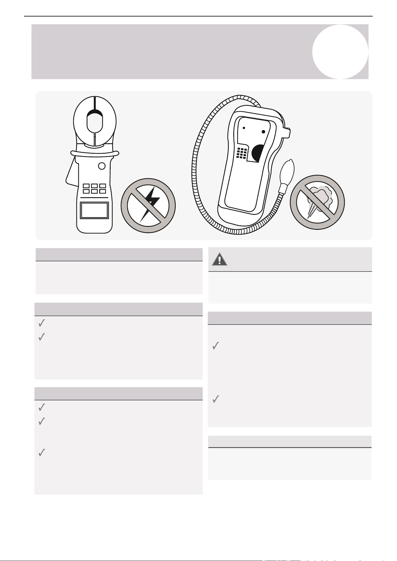
Page 48
Outdoor Unit
Installation
8
Outdoor Unit Installation Instructions
Evacuation Instructions (Cont’d)
Service
Port Nut
OPEN VALVE STEMS GENTLY
Flare Nut
Cap
When opening valve stems, turn the supplied Allen
wrench until the valve stem comes into contact with
stopper. Do not try to force the valve to open further.
2-Way Valve
Valve Body
Valve Stem
3-Way Valve
2-Way Valve
Valve Cap
2-Way Valve
Valve Cap
3-Way Valve
[11] Open 1/4 Turn
[15] Tighten
[15] Tighten
[15] Tighten
[14] Turn to Fully
Open Valve
3-Way Valve
[14] Turn to Fully
Open Valve
Indoor Unit
Step 11
Step 14
Step 15
Indoor Unit
Indoor Unit
Do not open
either of these
valves until
evacuation steps
are completed
and system is
ready for startup
(steps 11-15)
6.
Turn on the vacuum pump to evacuate the system.
7.
Run the vacuum for at least 15 minutes, or until the
Compound Meter reads -76cmHG (-100 kPa or -30
inHg). The vacuum reading should gradually lower.
8.
Close the low pressure knob of the manifold gauge,
and turn off the vacuum pump.
9.
For best results, wait for at least 1 hour, then verify
that there has been no rise in the vacuum reading.
10.
If there is a rise in the system vacuum, refer to “Gas
Leak Check” section for information on how to check
for leaks. If no change in vacuum reading, unscrew
the cap from the service valve (high pressure valve).
11.
Insert the Allen wrench into the service valve (2-way
valve) and open the valve by turning the wrench in a
1/4 counterclockwise turn. Wait and listen for gas to
exit the system, then close the valve after 5 seconds.
(If no sound is heard or change in reading occurs, refer to page 52.)
12.
Watch the pressure gauge for a few minutes to make
sure that there is no drop in pressure. The Gauge
should now show a positive reading. From this point,
it is best to do a leak check using soapy water spray.
13 .
If no leaks, remove the charge hose from the service port.
14.
Using a hexagonal wrench, fully open both the high
pressure and low pressure valves counterclockwise.
15.
Tighten valve caps on all three valves (service port,
high pressure, low pressure) by hand. Tighten further
using a torque wrench if needed.
47
Air Conditioner Installation & User Manual
10
Electrical/Gas Leak Check
& Test Run
Electrical Safety Checks
Before Test Run
After installation, confirm that all electrical wiring is
installed in accordance with local and national
regulations and the installation manual.
During Test Run
Gas Leak Checks
There are two methods to check for gas leakage:
Warning –
Risk of Electric Check
After Performing Gas Leak Checks
All wiring must comply with local and national
electrical codes and must be installed by a licensed
electrician.
After confirming that all the pipe connection points
do not leak, replace the valve cover on the outside
unit.
Soap and Water Method
Use a soft brush to apply soapy water or liquid
detergent to all pipe connection points on the
indoor and outdoor units. The presence of
bubbles indicates a leak.
Leak Detector Method
If using a leak detector, refer to the device's
operation manual for proper usage instructions.
Check for electrical leakage.
During the test run, use an electroprobe and
multimeter to perform a comprehensive electrical
leakage test.
If electrical leakage is detected, turn off the unit
immediately and call a licensed electrician to find
and resolve the cause of the leakage.
Note: This may not be required in some locations.
Check grounding work.
Measure grounding resistance by visual detection
or with a grounding resistance tester. Grounding
resistance must be less than 4Ω.
Note: This may not be required in some locations.
48
Air Conditioner Installation & User Manual
10
Electrical/Gas Leak Check
& Test Run
Before Test Run
Only perform a test run after the following steps
have been completed:
Test Run Instructions
Preform the following test run for 30 minutes:
After Test Run Completion
After the 10 boxes above have been checked and marked as passed, perform the following operation:
1. Use the remote control to return the system to a normal desired operating temperature.
2. Use the insulation tape to wrap the indoor unit's refrigerant pipe connections that were left uncovered
during the installation process.
If Ambient Temperatures Are Too High to Run a Heating Test:
If outside temperatures are too high to permit Heating mode on the remote, do the following:
1. Turn the unit on and put it in Heating mode using the emergency button as depicted on page 6.
2. Run the Heating mode test as normal and turn the unit back off using the button when complete.
Double Check All Pipe Connections
Test Run
Electrical Safety Checks
Confirm that the unit's electrical system is safe
and is operating properly.
Gas Leak Checks
Check all flare nut connections and confirm that
the system is not leaking.
Gas Leak Checks
Confirm that both the gas and liquid valves
(high/low) are 100% fully opened.
1. Connect power to the unit.
2. Press the On/Off button on the remote controller
to turn it on.
3. Press the Mode button to scroll through the
following functions, one at a time.
•
•
Cool - Select lowest possible temperature
Heat - Select highest possible
temperature
4. Let each function run for 5 minutes and perform
the following checks:
During operation, the pressure of the refrigerant circuit will increase. This may reveal leaks that were not
present during the initial leak check. Take time during the test run to double-check that all copper pipe
connection points are leak-free. Refer to the Leak Check page for instructions. Cooling mode pressure
should be 120-155 PSI. Heating mode pressure should be 320-450 PSI.
o Water drains from drain hose properly
o All piping is properly insulated
o Indoor unit responds to the remote controller
o Indoor unit louvers work properly
o System works in both Heat + Cool mode
o No electrical leaks or abnormal noises
o Unit is properly grounded
o All electrical terminals are properly covered
o Indoor and outdoor units are securely installed
o All pipe connections points do not leak
Pass/Fail?
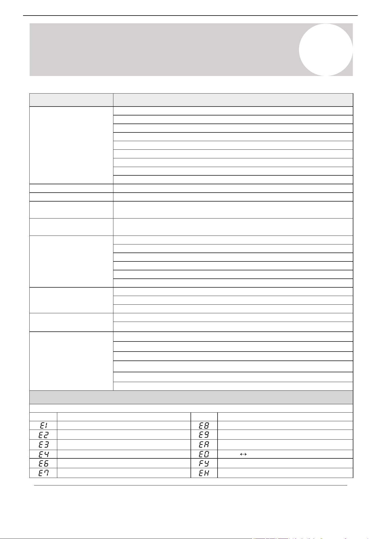
Page 50
9
Electrical/Gas Leak Check and Test Run
Test Run
PASS/FAIL?
BEFORE TEST RUN
Only perform a test run after the following
steps have been completed:
No Electrical Leaks or Abnormal Noises
Unit is Properly Grounded
All Electrical Terminals Properly Covered
Indoor and Outdoor Units Securely Installed
All Pipe Connections Points Do Not Leak
Water Drains From Drain Hose Properly
All Piping is Properly Insulated
Indoor Unit Responds to Remote Controller
Indoor Unit Louvers Work Properly
System Works in Both HEAT + COOL mode
TEST RUN INSTRUCTIONS
Opened Valves
Confirm that both the gas and liquid
valves (high/low) are 100% fully opened.
The following test run should be performed
for 30 minutes:
Electrical Safety Checks
Confirm that the unit’s electrical system is
safe and is operating properly.
Gas Leak Checks
Check all flare nut connections and confirm
that the system is not leaking.
AFTER TEST RUN COMPLETION
After the 10 boxes above have been checked as having PASSED, perform the following operation:
1. Using the remote control, return the system to a normal desired operating temperature.
2. Using insulation tape, wrap the indoor unit refrigerant pipe connections that were left uncovered
during the indoor unit installation process.
IF AMBIENT TEMPERATURES ARE TOO HIGH TO RUN A HEATING TEST:
If outside temperatures are too high to permit HEATING mode on the remote, do the following:
1. Turn the unit on and put it in heat mode using the emergency button as depicted on Page 8.
2. Run the heating mode test as normal, and turn the unit back off using the button when complete.
DOUBLE CHECK ALL PIPE CONNECTIONS
During operation, the pressure of the refrigerant circuit will increase. This may reveal leaks that
were not present during your initial leak check. Take time during the Test Run to double-check
that all copper pipe connection points are leak-free. Refer to the Leak Check page for instructions.
Cooling mode pressures should be 120-155 PSI. Heating mode pressures should be 320-450 PSI.
perform the following checks:
4.
Let each function run for 5 minutes, and
• COOL – Select lowest possible temperature
• HEAT – Select highest possible temperature
1. Connect power to the unit.
2.
Press the ON/OFF button on the remote
controller to turn it on.
3. Press the MODE button to scroll through
the following functions, one at a time:
Test Run
T
Troubleshooting
49
Air Conditioner Installation & User Manual
Malfunction
If there are strange odors...
If there is running water...
If the display is off...
If a fine mist is coming
from the air outlet...
If the airflow is
insufficient, and the
air is not hot or cold
enough...
If the appliance does not
respond to commands...
If the appliance
does not operate
or respond...
Error Signals on the Display
Possible Causes
There is a faulty compressor or thermomagnetic circuit breaker
The indoor / outdoor unit fan motor is damaged
The electrical connections are loose
There is a faulty protective device or fuses
The system has entered a protection mode
The system has entered an overvoltage or undervoltage protection
The air filter is dirty
The electronic control board was damaged
The Timer-On function is active
There is a back-flow of condensate water into the system’s drain pan.
This occurs when the air in the room becomes considerably cold. For example in “Cooling”
or “Dehumidification / Dry” modes
The temperature setting is unsuitable
The air conditioner intakes and outlets may be obstructed
The fan speed may be set at the minimum
This noise is made by the expansion or contraction of the front panel due to variations in
temperature. If so, this is normal
The air filter may be dirty
The system may be getting low on refrigerant. Pressures should be checked
There may be too many other heat sources in the room
The remote control may not be close enough to the indoor unit
The batteries of the remote control may need to be replaced
There are obstacles between the remote control and indoor unit signal receiver
The Display button has been pressed
Strange noises not due to expansion/contraction are heard during operation
There has been a power failure
The electronic control board is faulty or malfunctioning
Any fuses or switches are faulty or malfunctioning
The sound of spraying water or objects are heard inside the appliance
The cables or plugs have overheated
There are very strong odors being emitted from the appliance
Indoor temperature sensor fault
Display
Description o f the error
Outdoor pipe temperature sensor fault
Indoor pipe temperature sensor fault
Malfunction of the indoor fan motor
Refrigerant system leakage or fault
Outdoor air temperature sensor fault
Outdoor discharge temperature sensor fault
Display
Outdoor IPM module fault
Indoor Outdoor unit communication fault
Outdoor current detection fault
Description of the error
In case of errors, the display on the indoor unit may show the following codes:
Outdoor suction temperature sensor fault
Refrigerant leak / Low pressure detected
Do not attempt to use the system until the error code is diagnosed and resolved. Forcing the system to run can cause irreversible damage.
There is a power failure / plug pulled out or tripped / wrong breaker (wrong wiring)
If strange noises are being
emitted...
Switch off the air
conditioner immediately
and cut off the power
supply in the event of...
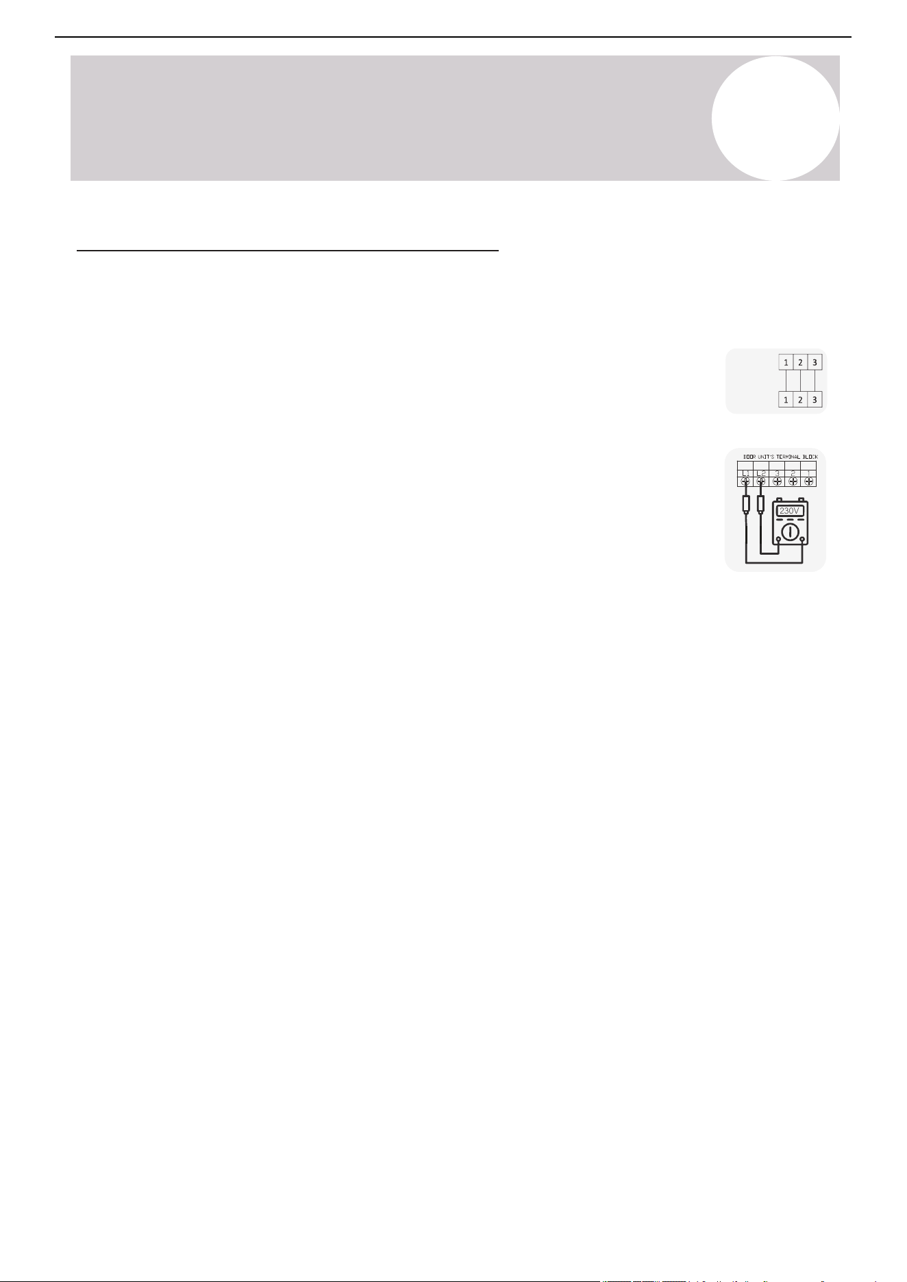
230V
INDOOR
UNIT
OUTDOOR
UNIT
[1]
[2]
Page 53
A
Appendix
Appendix
Anchoring the Outdoor Unit
The outdoor unit can be anchored to the ground or to wall-mounted brackets. The following
is a list of different outdoor unit sizes and the distance between their mounting feet. Prepare
the installation base of the unit according to the dimensions found below:
If installing the unit on the ground or on a
concrete mounting platform, do the following:
5. Hammer expansion bolts into each hole.
Underside View Front View Side View
6. Remove the nuts from expansion bolts, and
place the outdoor unit onto the bolts.
replace each of the nuts.
7. Put washers onto each expansion bolt, then
1. Mark the positions for four expansion bolts
based on dimensions in the “Unit Mounting
Dimensions” chart.
2. Pre-drill holes for expansion bolts.
3. Clean concrete dust away from holes.
4. Place a nut on the end of each expansion bolt.
Using a wrench, tighten each nut until snug.8.
WHEN DRILLING INTO CONCRETE,
WEAR EYE PROTECTION AT ALL TIMES!
FD
G
IH
J
K
E
Air Inlet
Air Inlet
Valve Set
Air Outlet
(When mounting on slab, installation of drain joint and tubing shown on page 40 is not necessary.)
Model D E F G H I J K
YN009GLSI25RPH
(9000 BTU - 230V)
YN012GLSI25RPH
(12000 BTU - 230V)
YN018GLSI25RPH
(18000 BTU - 230V)
YN024GLSI25RPH
(24000 BTU - 230V)
T
Troubleshooting
50
Air Conditioner Installation & User Manual
Solutions to Common Issues & Scenarios
Issue: The indoor air handler does not turn on
• Solution: Try the manual emergency button on the indoor unit in order to rule out
problems with the remote.
• Solution: Verify that the wire order is equal between the indoor and outdoor units [1].
The color order must match. Check for splices or damage on the control cable. To rule out
variables, remove any accessorial items, such as UV lights or condensate pumps, until the
problem is resolved.
• Solution for 230V systems: Use a multimeter to check the AC voltage across terminals
L1-L2 on the outdoor system [2]. Touch one probe to L1, the other probe goes on L2. Do
not measure each leg to ground. Verify whether the reading is between 208~253 VAC.
o If the reading is between 208~253 VAC, measure whether the reading is the
same across 2-3 on both the outdoor and indoor units. All readings must
match. The system must receive a full 230V reading in order to function.
o If the reading is 0 VAC, then the system is not receiving proper power from the
power source. Some common reasons are:
A fused disconnect is being used, but fuses are blown and not
inserted properly.
The disconnect box bus-bar is in the Off position.
A double-pole breaker is not being used. Single or tandem breakers
will not operate.
Issue: The pressure reading does not rise when releasing refrigerant during the leak
check
• Solution: Verify that the gauge tube pin on the manifold gauge is fully engaging the outdoor unit service port's
Schrader valve. A pin that is over or underexposed will not allow the gauge to access the refrigerant circuit,
preventing pressure measurement and/or proper vacuuming. The depressor pin inside the hose connector is
adjustable for proper Schrader valve engagement.
o A telltale sign that this is happening is whether the gauge reading goes to instant vacuum when the
pump is first turned on. This means only the gauge is being vacuumed.
o If so, vacuuming will need to be re-performed, since only the gauge itself was vacuumed.

T
Troubleshooting
51
Air Conditioner Installation & User Manual
Issue: The fan runs in Cooling mode but in Heating mode there is weak or no airflow
• Solution: The fan speed control is typically not available to the user in Heating mode. If the coil is unable to
heat up, then the fan will not run at speed. This may indicate low refrigerant as well.
Issue: The system indicates that a refrigerant leak is present
• Solution: Cut off the power to the system. Prepare a soapy water spray and spray the connection points
of the lineset. The point where the bubbles form is where the leak is located. Tighten the connection
and re-test the system. After the leak is repaired, re-charge the system.
Issue: The indoor air handler is leaking water
• Solution: Verify that the indoor unit is both horizontally and vertically leveled.
• Solution: Confirm that the drain tube is at a continuous downward pitch.
o Pour a cup of water over the indoor unit's coils so that it reaches the drain pan.
o Verify that the water drains out of the tube freely. If it doesn't, find the cause and correct it.
Solutions to Common Issues & Scenarios (Continued)
Issue: The system is not holding a vacuum
• Solution: A leak in the gauge hoses is likely. Repair the leak and check the vacuum pump.
• Solution: Check the connection points for proper contact and torque, then tighten if necessary.
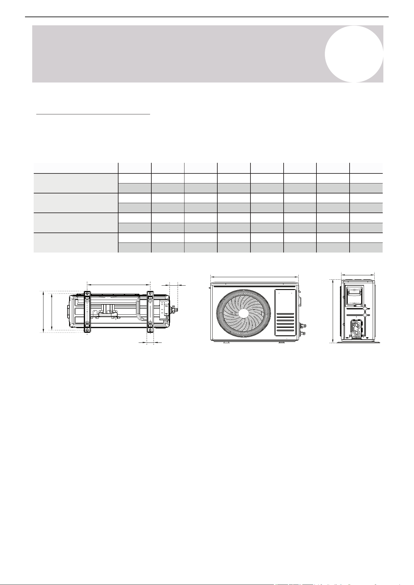
Page 52
T
Troubleshooting
Troubleshooting
Solutions to Commmon Issues and Scenarios
• Issue: The Indoor Air Handler Does Not Turn On.
▪ Solution: Verify that the wire order is equal between indoor and outdoor units
[1]
. Color
order must match. Check for splices or damage on the control cable. To rule out
variables, remove any accessorial items such as UV lights or condensate pumps until
the problem is resolved.
▪ Solution For 230V systems: Use a multi-meter to check AC voltage across terminals
L1-L2 on the outdoor system
[2]
(touch one probe to L1, the other probe goes on L2, do
not measure each leg to ground). Verify whether the reading is between 208~253 VAC.
◦ If the reading is between 208 and 253 VAC, measure whether the reading is
the same across 2-3 on both the outdoor unit, and the indoor unit. All readings
must match. The system must receive a full 230V reading in order to function.
◦ If the reading is 0 VAC, then the system is not receiving proper power from the
power source. Some common reasons are:
▫ A fused disconnect is being used, but fuses are blown or not inserted properly.
▫ The disconnect box bus-bar is in the OFF position.
• Issue: The pressure reading does not rise when releasing refrigerant during leak check.
▪ Solution: Verify that the gauge tube pin on the manifold gauge is fully engaging the outdoor unit
service port’s Schrader valve. A pin that is over or underexposed will not allow the gauge to access
the refrigerant circuit, preventing pressure measurement and/or proper vacuuming. The depressor
pin inside the hose connector is adjustable for proper Schrader valve engagement.
◦ A telltale sign that this is happening is whether the gauge reading goes to instant vacuum
when the pump is first turned on. This means only the gauge is being vacuumed.
◦ If so, vacuuming will need to be re-performed, since only the gauge itself was vacuumed.
• Issue: The system is not holding a vacuum.
▪ Solution: A leak in the gauge hoses is likely. Repair the leak and/or check the vacuum pump.
▪ Solution: Check the connection points for proper contact and torque and tighten if necessary.
• Issue: The indoor air handler is leaking water
▪ Solution: Verify that the indoor unit is both horizontally and vertically level.
▪ Solution: Check that the drain tube is at a continuous downward pitch.
◦ Pour a cup of water over the indoor unit’s coils so that it reaches the drain pan.
◦ Verify that the water drains out of the tube freely. If it doesn’t, find the cause and correct it.
• Issue: The system indicates that a refrigerant leak is present.
▪ Solution: Cut off power to the system. Prepare a soapy water spray, and spray the connection
points of the line set. The point where bubbles form is where the leak is located. Tighten the
connection and re-test the system. Have the system re-charged only after the leak is repaired.
• Issue: The fan runs in cooling mode but in heating mode there is weak or no airflow.
▪ Solution: Fan speed control is typically not available to the user in heating mode. If the coil is
unable to heat up then the fan will not run at speed. This may indicate low refrigerant as well.
230V
▫ A double-pole breaker is not being used. Single or tandem breakers will not work.
▪ Solution: Try the manual emergency button on the indoor unit, to rule out problems with the remote.*
*See Page 8
INDOOR
UNIT
OUTDOOR
UNIT
[1]
[2]
Model D E F G H I J K
YN009GLSI25RPH
(9000 BTU - 230V)
YN012GLSI25RPH
(12000 BTU - 230V)
YN018GLSI25RPH
(18000 BTU - 230V)
YN024GLSI25RPH
(24000 BTU - 230V)
A
Appendix
741 mm
794 mm
847 mm
910 mm
551 mm
602 mm
699 mm
804 mm
253 mm
288 mm
326 mm
353 mm
434 mm
516 mm
586 mm
607 mm
305 mm
349 mm
375 mm
421 mm
278 mm
314 mm
347 mm
390 mm
48 mm
54 mm
59 mm
63 mm
56 mm
51 mm
48 mm
54 mm
29-¼ in
31-¼ in
33-⅜ in
35-⅞ in
21-¾ in
23-¾ in
27-½ in
31-⅝ in
10 in
11-⅜ in
12-⅞ in
13-⅞ in
17-⅛ in
20-⅜ in
23-⅛ in
23-⅞ in
12 in
13-¾ in
14-¾ in
16-⅝ in
11 in
12-⅜ in
13-⅝ in
15-⅜ in
1-⅞ in
2-⅛ in
2-⅜ in
2-½ in
2-¼ in
2 in
1-⅞ in
2-⅛ in
52
Air Conditioner Installation & User Manual
Anchor the Outdoor Unit
The outdoor unit can be anchored to the ground or to wall-mounted brackets. The following is a list of different
outdoor unit sizes and the distance between their mounting feet. Prepare the installation base of the unit
according to the dimensions found below:
Underside view Front view Side view
F
D
G
I
H
J
K
E
Air inlet
Air inlet
Valve set
Air outlet
If installing the unit on the ground or a concrete
mounting platform, complete the following:
1.
Mark the positions for 4 expansion bolts based
on the dimensions in the “Unit Mounting
Dimensions” chart.
2.
3.
4.
Pre-drill holes for the expansion bolts.
Clean concrete dust away from the holes.
Place a nut on the end of each expansion bolt.
5.
Hammer expansion bolts into each hole.
6.
Remove the nuts from the expansion bolts and
place the outdoor unit onto the bolts.
7.
Put washers onto each expansion bolt, then
replace each of the nuts.
8.
Using a wrench, tighten each nut until snug.
WHEN DRILLING INTO CONCRETE, WEAR EYE
PROTECTION AT ALL TIMES!
When mounting on slabs, the installation of the drain joint and tubing shown on page 38 is not necessary.
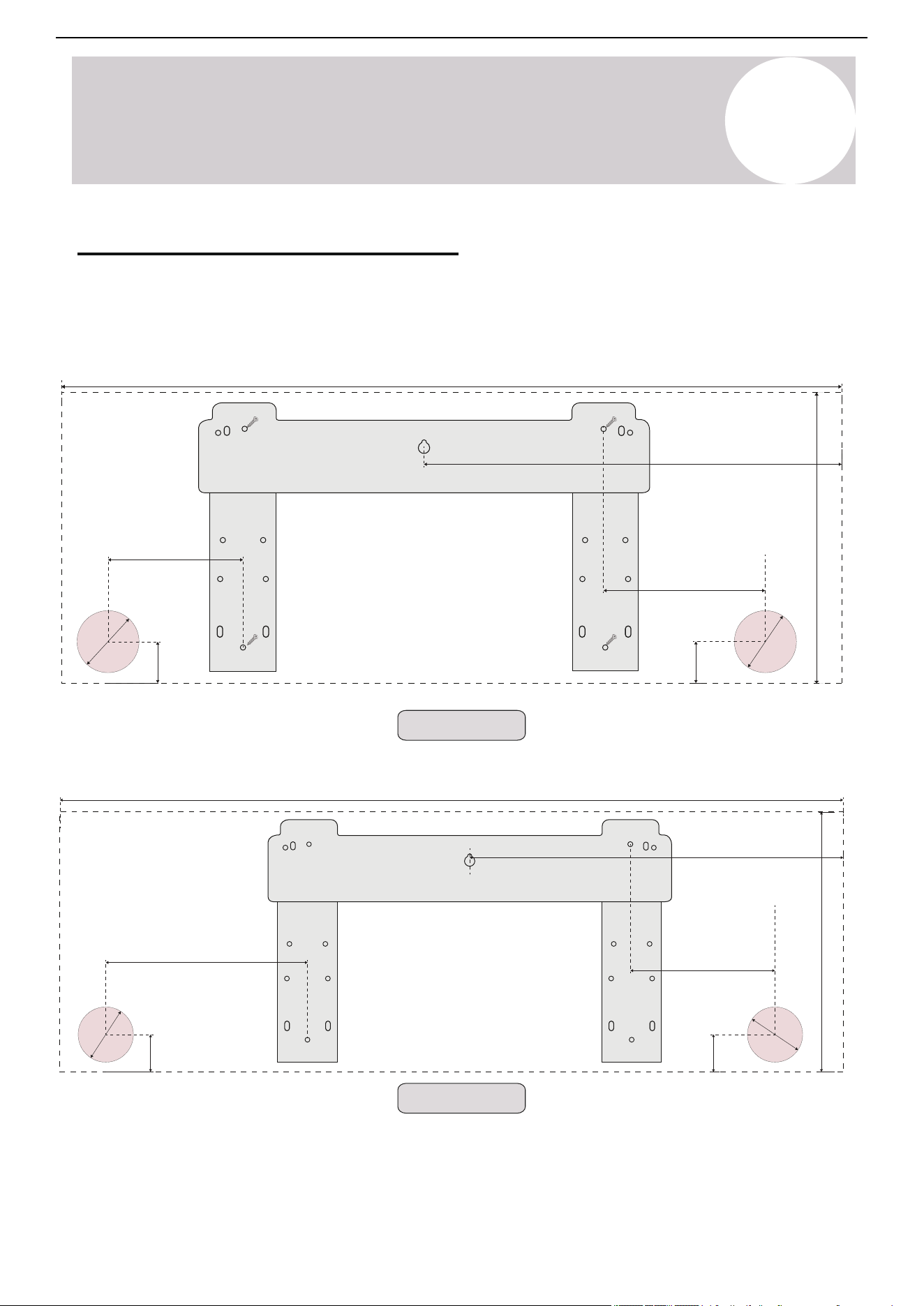
Page 55
A
Appendix
Appendix
Guidelines for Drilling the Wall Hole (continued)
Simplified Wiring Diagram (230V)
Right Side ExitLeft Side Exit
(For 18K, 24K Systems)
All Distances in Inches
Signal Cable to Outdoor Unit
Indoor Unit Terminal Block
1 ( S )
2(
N
)
3( L
)
13 in
43-1/4 in
ø 2-1/2 in
ø 2-1/2 in
9-3/4 in
1-3/4 in
6-7/8 in
22-3/8 in
1-3/4 in
A
Appendix
(For 12K Systems)
All Distances in Inches
Right side exit
Left side exit
(For 9K Systems)
All Distances in Inches
Right side exit
Left side exit
1-¾ in
(44 mm)
1-¾ in
(44 mm)
ø 2-½ in
.35 mm)(6
.35 m
ø 2-½ in
)(6 m
35 mm)
ø 2-½ in
(6.
(6.35 m
ø 2-½ in
m)
1-¾ in
(44 mm)
1-¾ in
(44 mm)
9-⅜ in (238 mm)
6-¾ in (171 mm)
12 in
(305 mm)
36-¼ in (921 mm)
17-¼ in (438 mm)
12 in
(305 mm)
(438 mm) in17-¼
6-¾ in (171 mm)
32-¼ in (819 mm)
5-⅝ in
(143 mm)
Guidelines for Drilling the Wall Holes
Below are the suggested locations for the wall holes for systems between 9,000 - 24,000 BTU. Both left side
and right side exits are considered with a 2-½ inch (63.5 mm) hole. Confirm the holes are proper by corner
tracing.
53
Air Conditioner Installation & User Manual
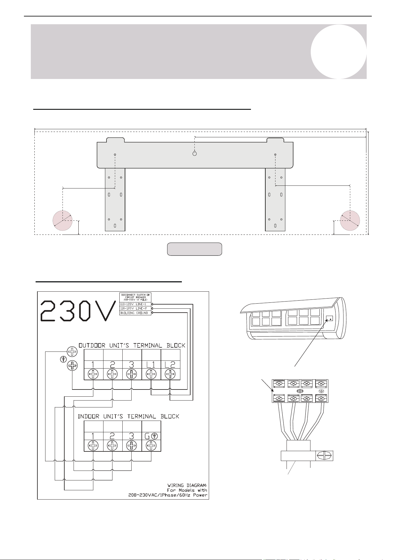
Page 54
A
Appendix
Appendix
Guidelines for Drilling the Wall Hole
Below are the suggested locations for the wall hole for systems between 9,000 - 24,000 BTU. Both
left side/right side exits are considered with 2-1/2” hole. Confirm holes are proper by corner tracing.
(For 9K Systems)
All Distances in Inches
(For 12K BTU Systems)
All Distances in Inches
Left Side Exit
Right Side Exit
Left Side Exit
Right Side Exit
32-1/4 in
12 in
1-3/4 in
6-3/4 in
17-1/4 in
ø 2-1/2 in
ø 2-1/2 in
1-3/4 in
5-5/8 in
36-1/4 in
12 in
1 3/4 in
6-3/4 in
ø 2 1/2 in
9-3/8 in
17-1/4 in
1-3/4 in
ø 2-1/2 in
Signal cable to outdoor unit
Indoor unit terminal block
1 ( S )
2(
N
)
3( L
)
A
Appendix
Simplified Wiring Diagram (230V)
Guidelines for Drilling the Wall Holes (Continued)
Right side exitLeft side exit
22-3/8 in
43-¼ in (1,098.5 mm)
9-¾ in (248 mm)
6-⅞ in (175 mm)
13 in (330 mm)
1-¾ in
(44 mm)
1-¾ in
(44 mm)
ø 2-½ in
3.5 mm)(6
3.5 m
ø 2-½ in
)(6 m
(For 18K, 24K Systems)
All Distances in Inches
54
Air Conditioner Installation & User Manual
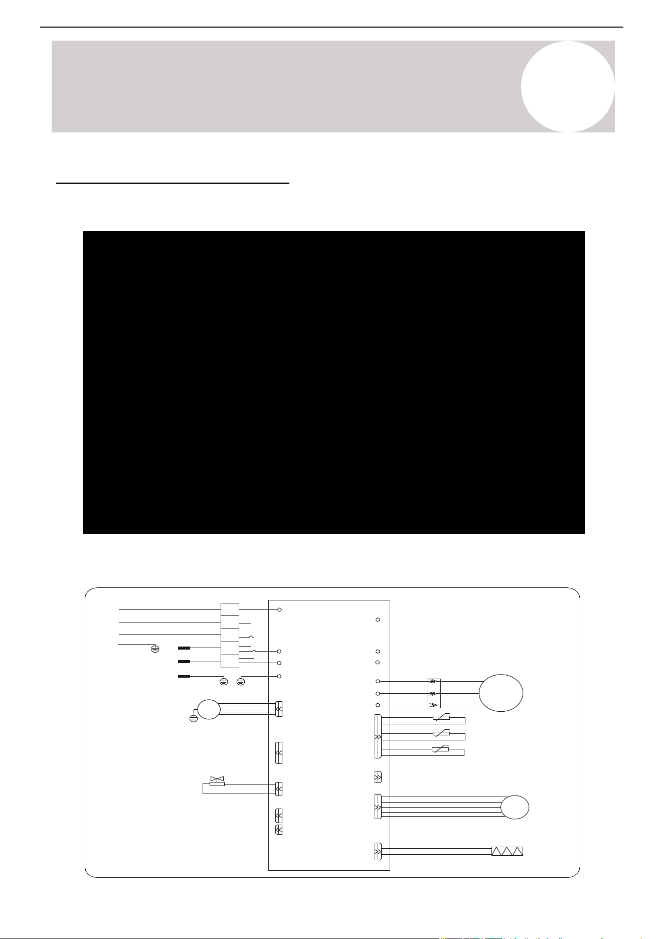
Outdoor Unit: YN009GLSI25RPH, YN012GLSI25RPH, YN018GLSI25RPH, YN024GLSI25RPH
OUTDOOR UNIT
YE(BY)
INDOOR
WH(BU)
UNIT
BK(BN)
POWER
GN(GNYE)
SUPPLY
WH(BU)
BK(BN)
GN(GNYE)
BK
GNYE(GN)
BU
BU
BN
BN
P3(S)
P2(AC-N)
PO(GND)/POO
P1(AC-L)
P01(GND)
P13(L1)
1
2
3
L2
L1
P14(L2)
U
V
W
U
V
W
RD
RD
WH
WH
BU
BU
COMP
BCP
OUTDOOR ENVIRONMENT TEMP. SENSOR
OUTDOOR PIPE TEMP. SENSOR
OUTDOOR EXHAUST TEMP. SENSOR
EEV
HEATER
ELECTRONIC EXPANSION VALVE
CN11
CN7
CN3
CN2/CN1
CN12-2
CN12-1
EXTERNAL DRIVE
P8(VAL)
CN410
P9
CN12-2
(P9)
GNYE
VALVE
MOTOR
DC FAN
Page 57
A
Appendix
Appendix
For Systems with Additional Leakage Sensor (If Applicable)
Condition Error Code
Refrigerant Leak Detected Display “Hd”
Communication Error with Refrigerant Sensor Display “Fd”
A
Appendix
Control Board Wiring Diagrams
Indoor Unit: WT009GLSI25HLH, WT012GLSI25HLH, WT018GLSI25HLH, WT024GLSI25HLH
55
Air Conditioner Installation & User Manual
A
Appendix
For Systems with Additional Leakage Sensor - If Applicable (Continued)
Important Notes:
• The sensor's installation position is illustrated below. Note: The actual location may vary depending on the
model and cabinet design.
• Use the sensor only in certain specific installation scenarios that may call for an auxiliary refrigerant leak
sensor to be installed. All indoor units possess leak sensing abilities, while only some installations require a
separate sensor. Qualified personnel must maintain the refrigerant sensor. Only use sensors specified by the
manufacturer as replacements.
• The refrigerant sensor has a design life of 15 years. Replace the sensor within its service life.
• The sensor automatically monitors the system operation. If refrigerant concentration exceeds the alarm
threshold, the system will stop the compressor and start the circulation fan for safety.
• The alarm indicators for the refrigerant sensor are shown below:
Condition
Error Code
Refrigerant Leak Detected
Communication Error with Refrigerant Sensor
Display "Hd"
Display "Fd"
56
Air Conditioner Installation & User Manual
Position of leakage
detection sensor
• The unit is equipped with a refrigerant leak detector for safety. The unit must remain electrically powered at all
times after installation, except during service.
• Only use manufacturer-approved sensors as replacements.

A
Appendix
57
Air Conditioner Installation & User Manual
For Systems with Additional Leakage Sensor - If Applicable (Continued)
If the air handler is configured with a refrigerant leakage detection sensor from the factory or
will be configured for one later, follow the alternative control board wiring diagram shown
below:

A
Appendix
58
Air Conditioner Installation & User Manual
Download iOS App
Download Android App
For Systems with a Wireless Internet Module (If Applicable)
Instructions for getting your system connected to Pioneer
®
Airlink
Search for "Pioneer Airlink" in the Google Play Store (for Android users) or the App Store (for iOS users). Note:
A 2.4GHz Wi-Fi connection is needed to use the Wi-Fi control feature.
Begin by ensuring the Internet module is securely plugged into the indoor air handler. Next download the app
from the store and enter the setup phase in the app where it asks to reset the system. After doing so,
complete the following:
1. Turn off the unit using the remote controller.
2. Turn off the circuit breaker that is powering the outside unit for 10 seconds. Then turn it back on.
3. Turn on the unit using the remote controller.
4. Press the "DISPLAY" button on the remote controller six times in a row within 6 seconds.
5. The indoor unit will flash "AP" (Access Point) or "CF" (Config) on the LED display.
6. The unit is ready to pair. Proceed through the prompts within the application.
7. The unit will be paired. Repeat these steps for any other units.
Page 59
A
Appendix
Appendix
If Refrigerant Has Been Added to the System During Install
System Notes
(For the Installer) Please fill in the following:
1) The factory refrigerant charge of the product (located on the outdoor unit nameplate).
2) The additional refrigerant charged into product.
1+2) The total refrigerant charge.
Instruct the user to retain this information for reference during future service and maintenance.
kg (ozs)
kg (ozs)
kg (ozs)
A
Appendix
59
Air Conditioner Installation & User Manual
Special Notice
Disposing of this appliance improperly, or in other natural surr oundings, endangers your
health and is bad for the environment. Hazardous substances may leak into the gr ound water
and enter the food chain. Follow proper disposal protocols.
• Dispose of the appliance at a designated municipal electronic waste collection facility.
• When buying a new appliance, the retailer will take back the old appliance free of charge.
• The manufacturer will take back the old appliance free of charge.
• Sell the appliance to certified scrap metal dealers.
Product Disposal Guidelines
This appliance contains refrigerant and other potentially hazardous materials. When
disposing the appliance, the law requires special collection and treatment. Do not dispose this
product as household waste or unsorted municipal waste.
Remove all refrigerant and oil prior to disposal as outlined within this manual.
When disposing of this appliance, the following options are available:
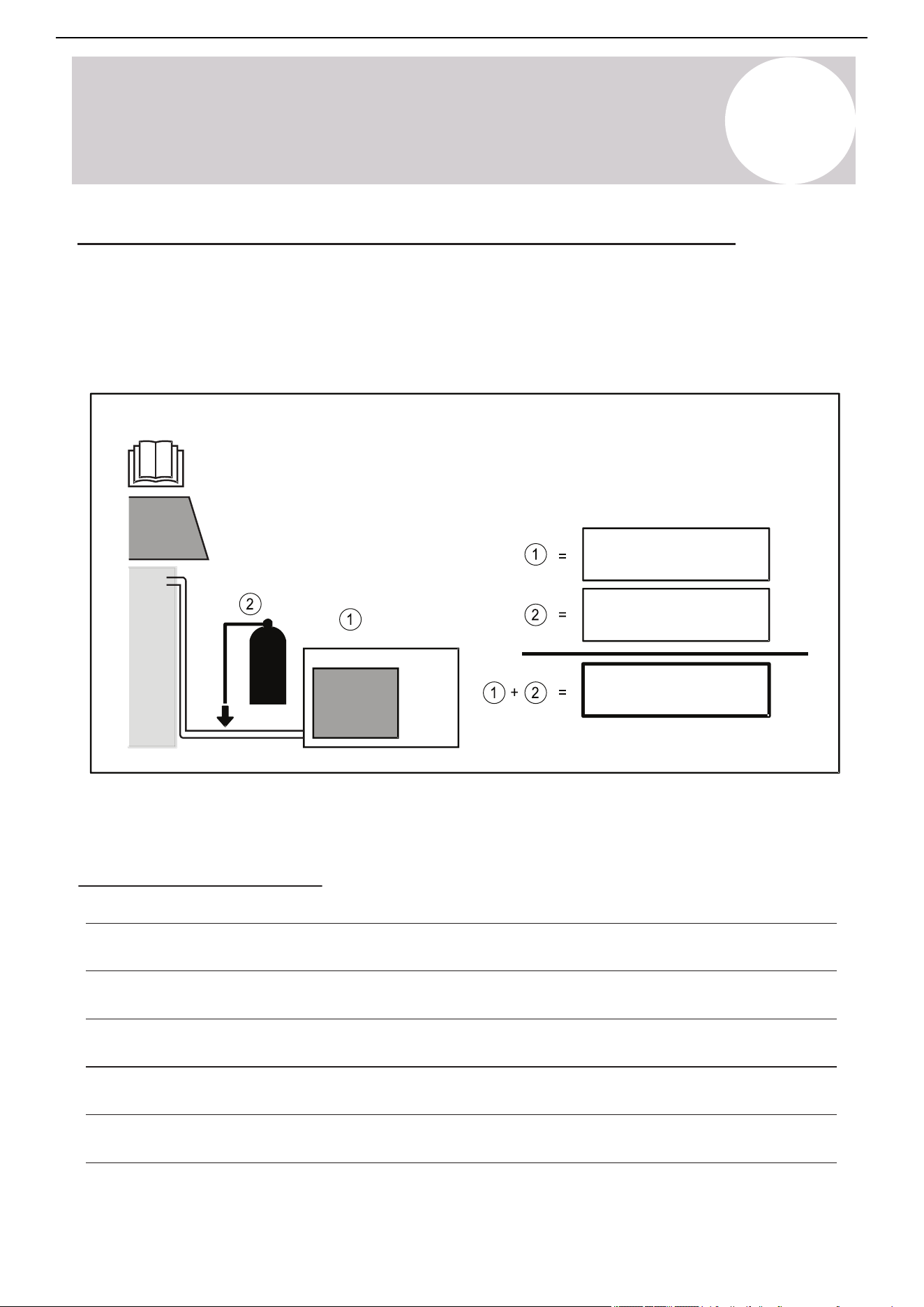
A
Appendix
If Refrigerant Has Been Added to the System During Installation
(For the Installer) fill in the following:
1) The factory refrigerant charge of the product (located on the outdoor unit nameplate).
2) The additional refrigerant charged into the product.
1+2) The total refrigerant charge.
We recommend keeping this information handy for future service and maintenance needs.
System Notes
ozs (kg)
ozs (kg)
ozs (kg)
60
Air Conditioner Installation & User Manual

The design and specifications of this product are subject to change without prior notice
as development continues. Consult with the sales agency or manufacturer for details.
Refer to the equipment nameplate for all other applicable specifications.
Copyright 2025, Parker Davis HVAC International, LLC., All rights reserved.
is a registered trademark of Parker Davis HVAC International, LLC.
Parker Davis HVAC International
7290 NW 77 Court, Miami, FL 33166 - USA
Tel
: (305) 513-4488
Fax
: (305) 513-4499
E-mail
Website: www.pdhvac.com
Pioneer product line, parts, and supplies are
available online for convenient ordering at:
www.highseer.com
www.pioneerminisplit.com
Scan the below code to visit our support page
where you can find more installation materials:
61