Page 1
1. Disassembly
1. Electrical parts (Antistatic gloves must be worn.)
Pr
ocedur
e Illustration
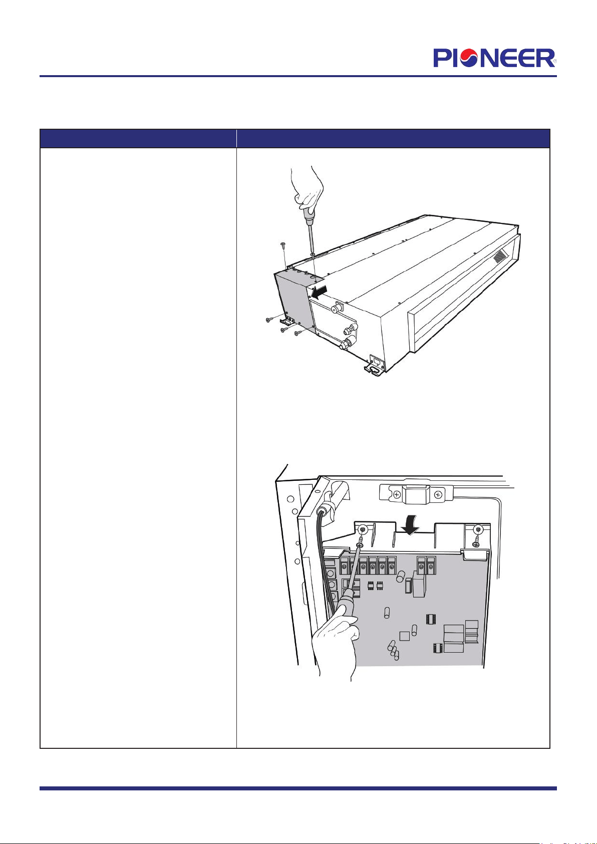
1) Remove 5 screws of the cover of
electronic control box and then
remove the cover. (see Figure 1.)
2) Remove the 2 screws of the electronic
control box. Then release the 2
hooks of the main control board.
(see Figure 2).
Figure 1
Figure 2
Note: This section is for reference only. Actual unit appearance may vary.
Disassembly Guide for RYB/RB Slim-Duct Concealed Air Handler
Applies to Models with Nomenclature of "RBxxxGMFILxFHD".
Page 2
Procedure Illustration
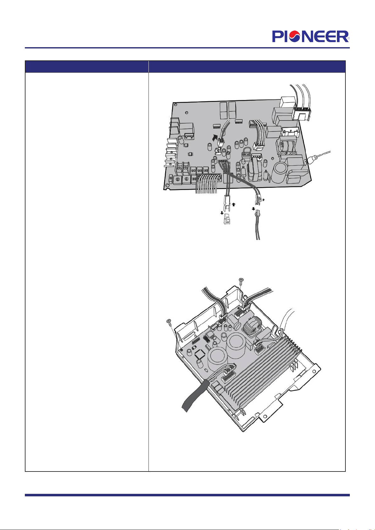
3) Disconnect the connectors and then
remove the front main control
board (see Figure 3).
4) Turn over the electronic control box.
Disconnect the connectors and remove
the 2 screws of rear main control
board (see Figure 4).
Figure 3
Figure 4
Note: This section is for reference only
. Actual unit appearance may vary.
Procedur
e Illustration
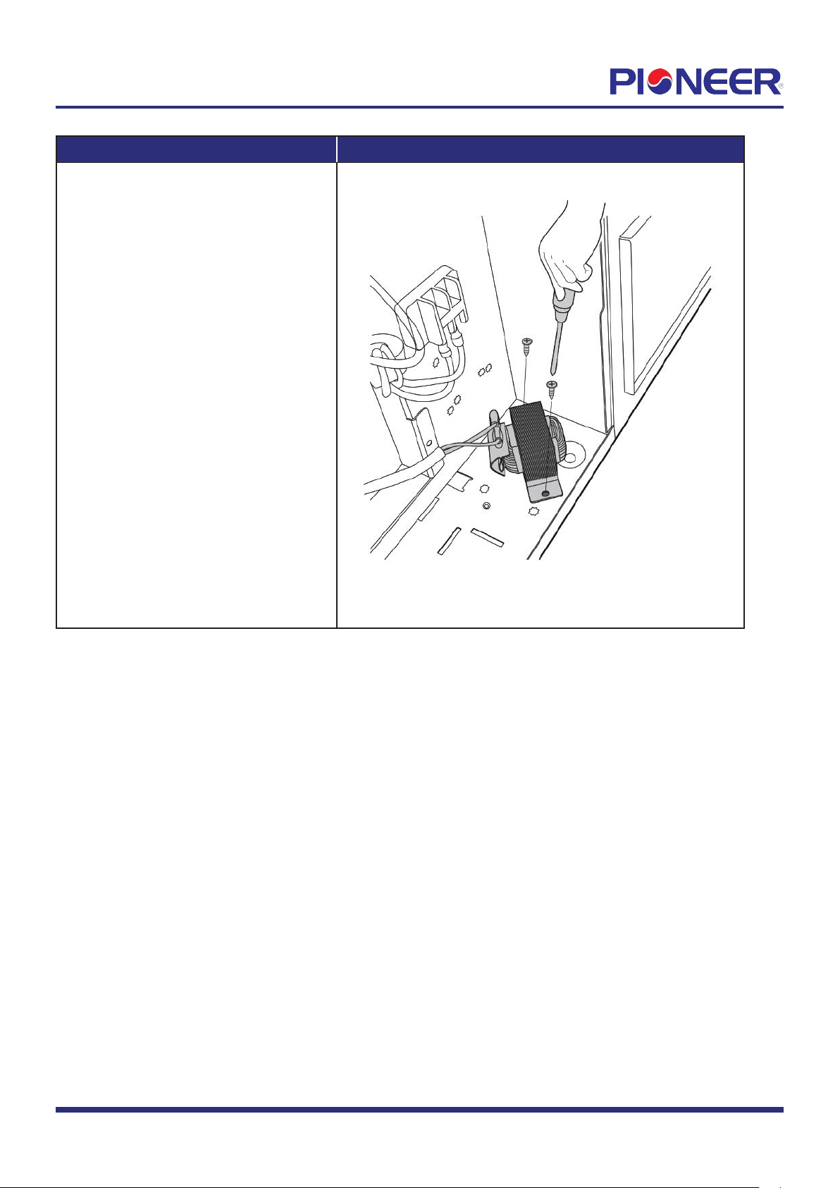
5) Remove 2 screws of reactor and remove
the reactor (see Figure 5).
Figure 5
Note: This section is for reference only. Actual unit appearance may vary.
Page
3
2. Fan motor and fan
Pr
ocedure Illustration
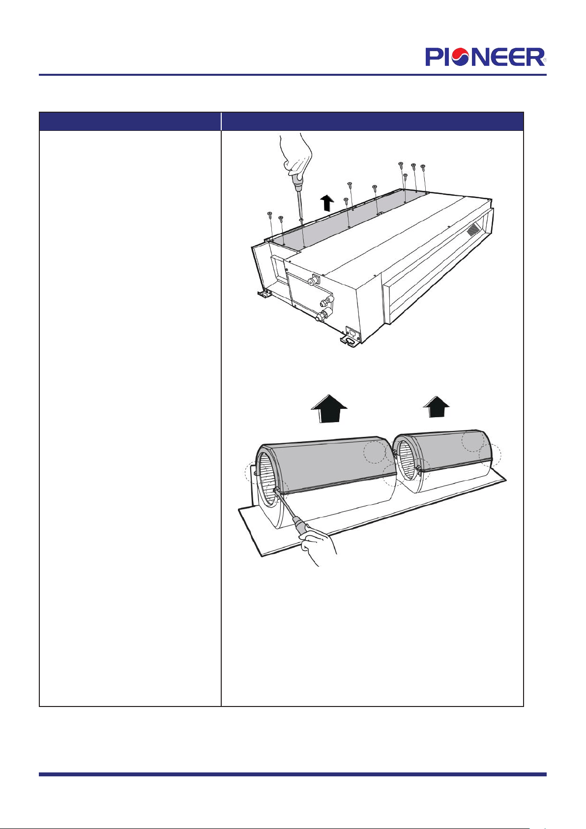
1) Remove 10 screws of the top cover
and then remove the top cover
(see Figure 6).
2) Release the 8 hooks of volute shell
(see Figure 7).
Figure 6
Figure 7
Note: This section is for r
eference only. Actual unit appearance may vary.
Page
4
Procedure Illustration
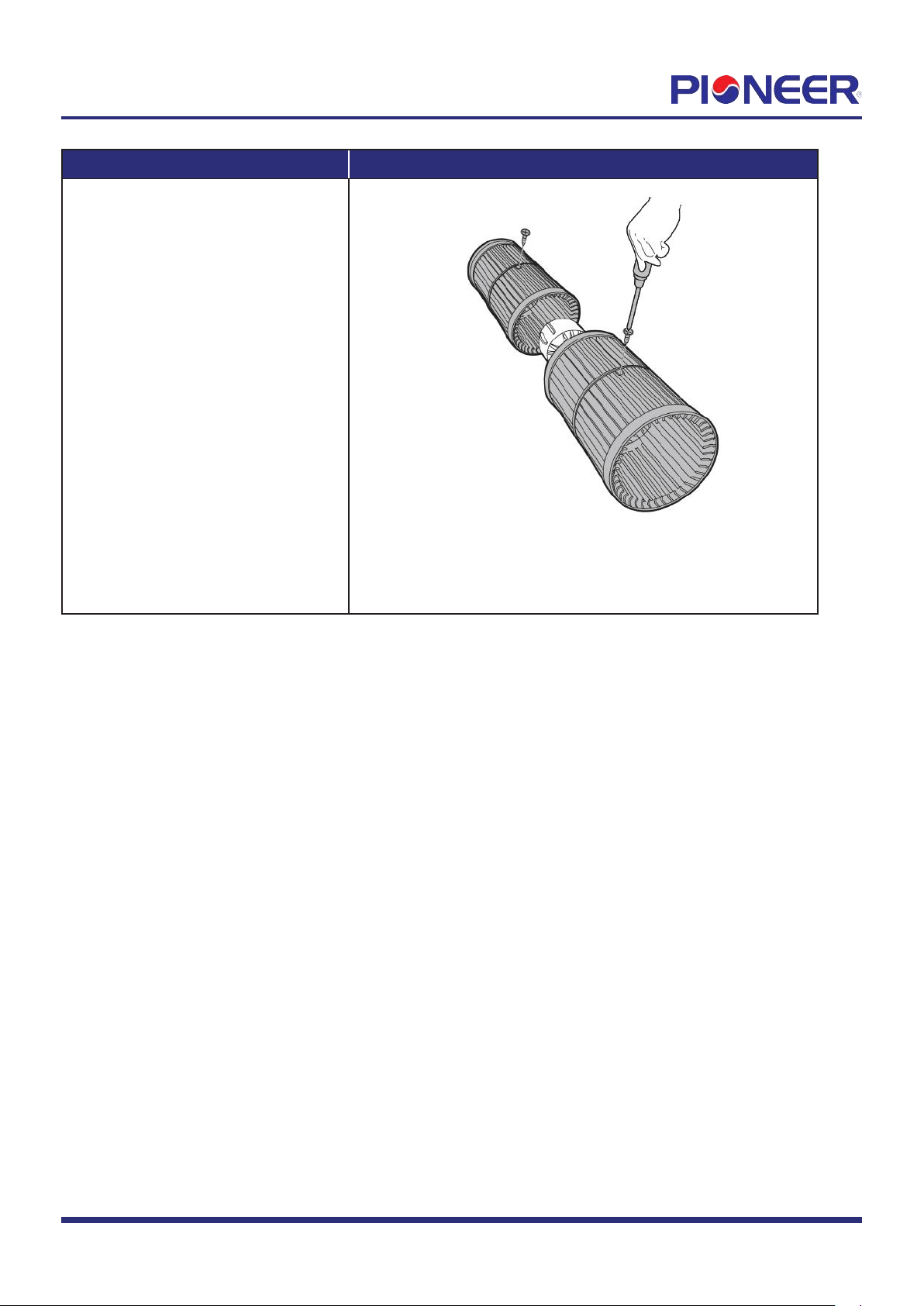
3) Remove the fixing screws of fan (2
screws) (see Figure 8).
Figure 8
Note: This section is for reference only
. Actual unit appearance may vary.
Page
5
3. Evaporator
Pr
ocedure Illustration
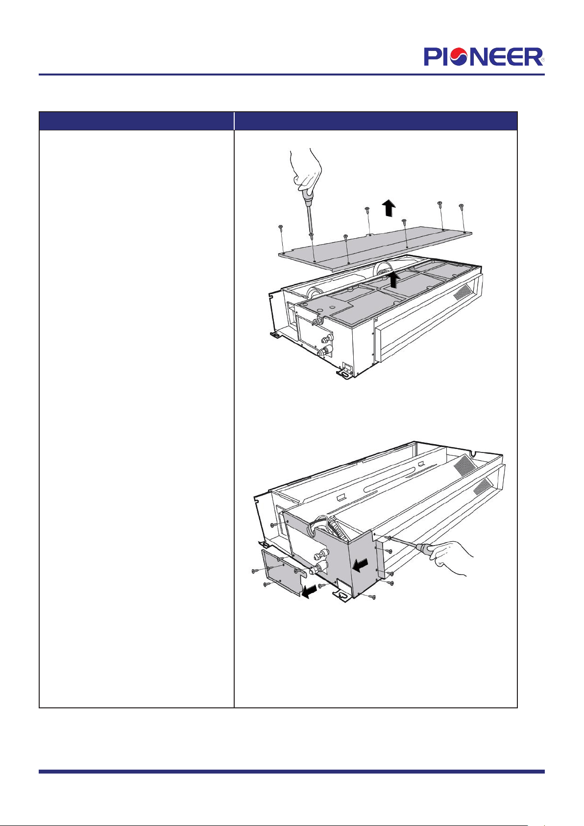
1) Remove 9 screws of the water collector
and remove the water collector
(see Figure 9).
2) Remove the screws of the pipe clamp
board and the left side board (3 for
the pipe clamp and 9 for left side
board) (see Figure 10).
Figure 9
Figure 10
Note: Remove the fr
ont panel (refer to 1. Front panel) before disassembling electrical parts.
Page
6
Pr
ocedure Illustration
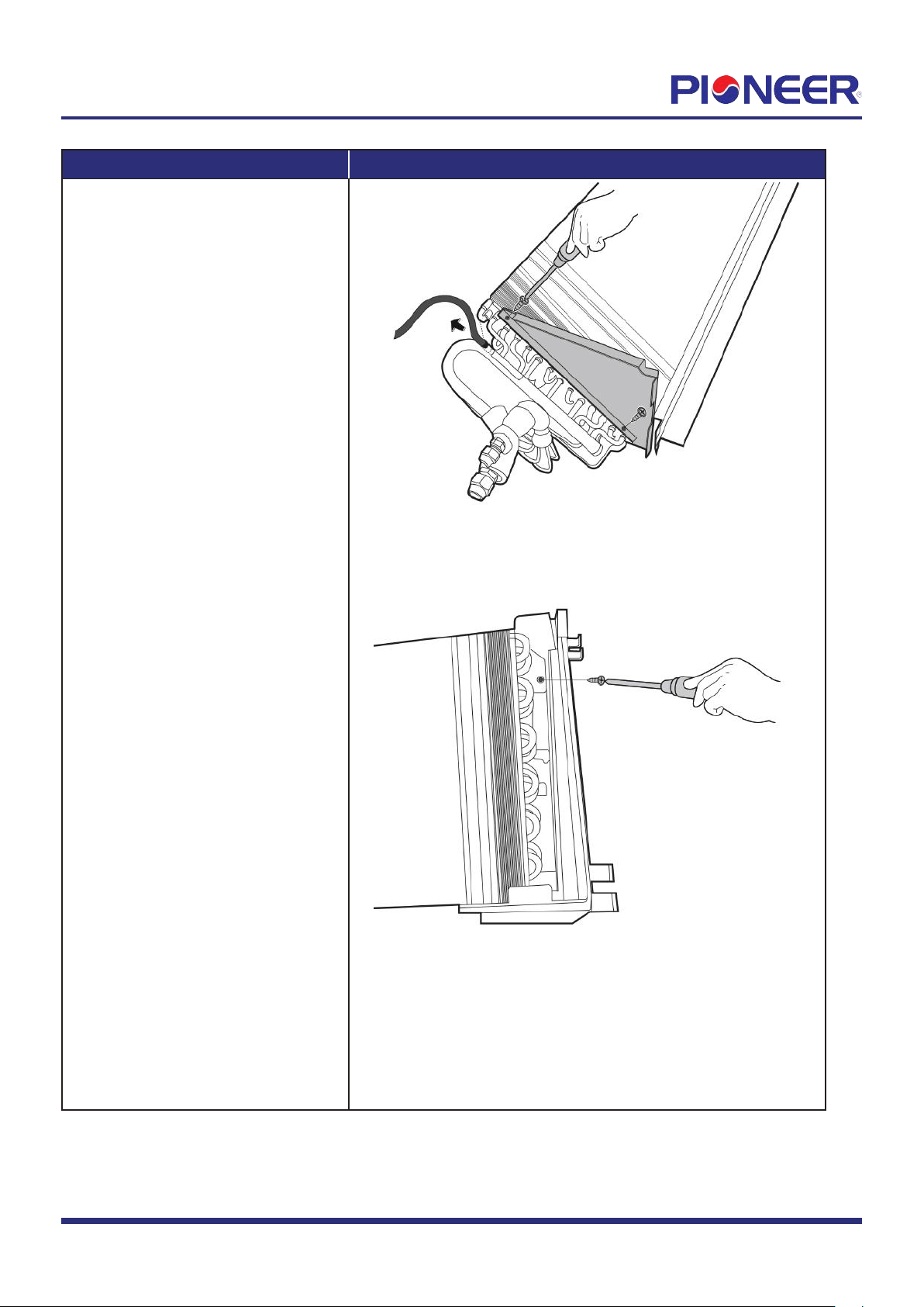
3) Remove the 2 fixing screws of the
evaporator support and then
pull up the temperature sensor
(see Figure 11).
4) Remove the fixing screw of the
evaporator and then remove it
(see Figure 12).
Figure 11
Figure 12
Note: This section is for r
eference only. Actual unit appearance may vary.
Page
7