– 1 –
Quick Start Guide
E092026-CS-R01
wifi.edge-core.com
Wi-Fi 7 Access Point
EAP105s
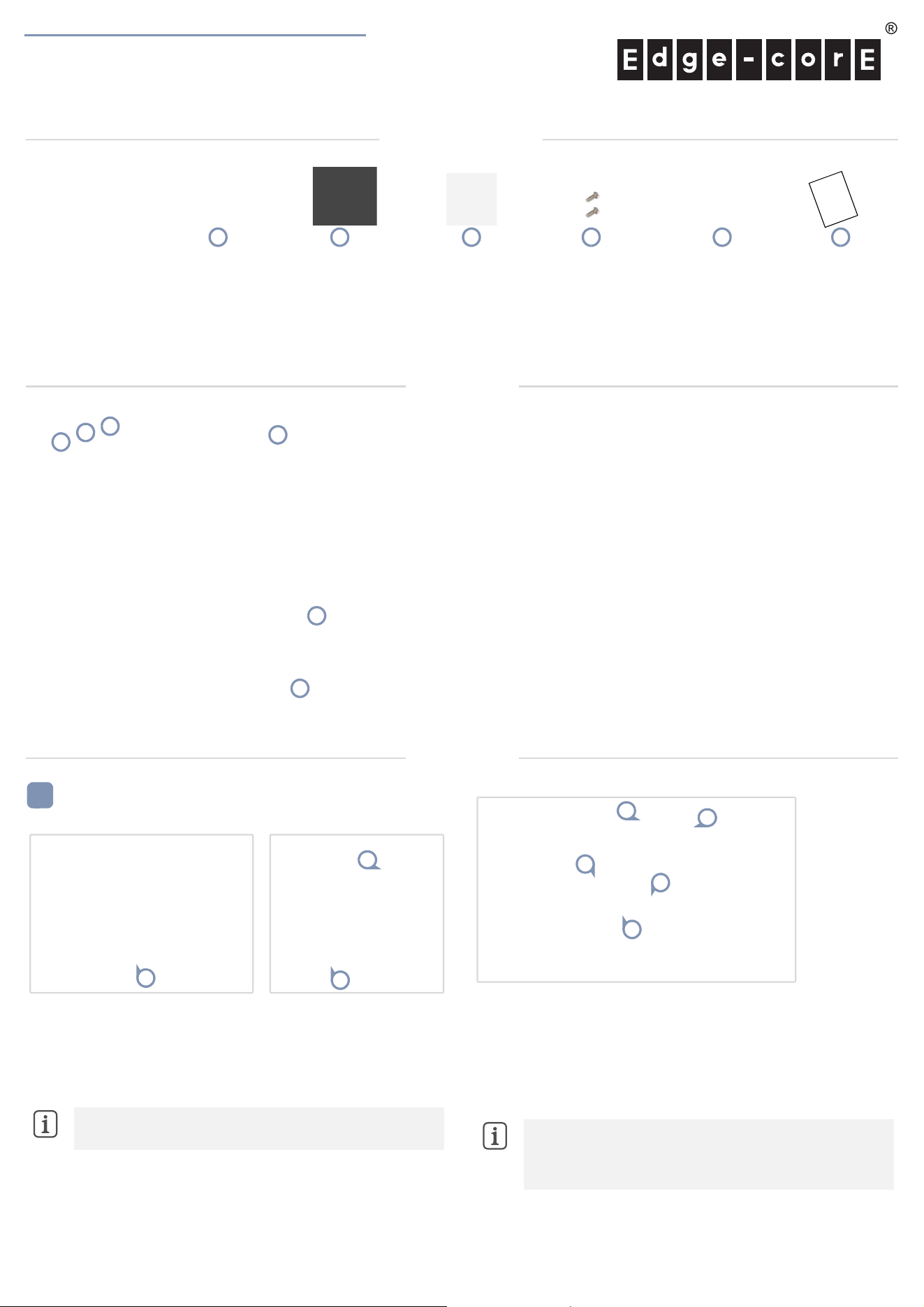
Package Contents
Mount the AP
a. Mounting on a Wall
1.
At the installation location on the wall, use the mounting bracket to
mark four holes for the wall plugs and screws (included in the screw
kit).
Drill four holes for the wall plugs, and then insert the plugs and tap
them flush with the wall surface.
Use the four screws to secure the bracket to the wall.
2. With its System LED at the top, place the AP over the bracket flanges
and then slide it down until it snaps into its secured position.
3. Use the bracket’s thumb screw to secure the AP to the bracket.
b. Mounting on a Suspended Ceiling T-Bar
1.
Slide the bracket accessory onto the base of the AP and secure it
using the
bracket’s thumb screw
.
2. Use the two included security screws to completely secure the
bracket to the AP.
3. Position the ceiling-mount clip holders on either side of the T-bar,
and then turn the AP until the two clips lock it to the T-bar.
Note:
Drill 2.5 mm (±0.2 mm) holes for M3 self-tapping
screws, or 4.5 mm (±0.2 mm) holes for nylon wall plugs.
1
2
1
3
Note:
The AP mounting supports two different sizes of
suspended ceiling T-bars. The position illustrated above is for
15 mm bars. Use the position at a 90 degrees angle for
24.5 mm bars.
3
2
1
2
3
Overview
Installation
1.
DC jack, 12 VDC input
2. Uplink (PoE) Port: 5GBASE-T, 802.3at PoE
3. Console port
4. Restart/Reset button:
A quick press restarts the system.
Press and hold for 5 seconds resets to factory defaults.
5. System LED Indicator:
Green: On (power OK), Blinking (boot up)
Blue: On (cloud managed)
Purple: Blinking (uplink activity in cloud-managed mode)
Orange: Blinking (uplink activity in stand-alone mode)
6. Kensington lock slot
2
3
4
1
6
5
1.
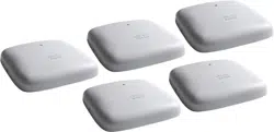
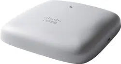
EAP105s access point
2. Mounting bracket accessory
3. Ceiling plate
4. 2 x Mounting bracket security screws
5. Screw kit—4 screws and 4 plugs
6. QR code label
1
2 4 5 63
Edgecore
Quick Start Guide
– 2 –
c. Mounting on a Ceiling Without T-Bars
1.
At the installation location on the ceiling, use the mounting bracket to
mark and drill four holes for the screws (included in the screw kit).
Place the ceiling plate on the
top side of the ceiling
surface.
Use the four screws to secure the bracket to the
ceiling plate through
the ceiling material (screw torque must be less than 6 kgf.cm)
.
2. Place the AP over the bracket flanges and then slide it onto the
bracket until it snaps into its secured position.
3. Use the bracket’s thumb screw to secure the AP to the bracket.
d. Mounting Over a Wall Junction Box
1.
At the wall junction box, use the mounting bracket to mark four holes
for the wall plugs and screws (included in the screw kit).
Drill four holes for the wall plugs, and then insert the plugs and tap
them flush with the wall surface.
Use the four screws to secure the bracket to the wall.
2. Feed cables from the junction box through the center hole of the
bracket and connect them to the AP.
3. With its System LED at the top, place the AP over the bracket flanges
and then slide it down until it snaps into its secured position.
4. Use the bracket’s thumb screw to secure the AP to the bracket.
Connect Cables
a. Connect LAN Cables
1.
Connect Category 5e or better cable to the Uplink (PoE)
5GBASE-T
RJ-45 port. When connected to a PoE source, the Uplink (PoE) port
connection provides power to the unit.
b. (Optional) Connect AC Power Adapter
2. When not connected to a PoE source, connect the AC power
adapter to the DC jack on the AP and then plug the adapter into a
nearby AC power source.
Check the System LED
1.
When operating normally, the System LED should be on green.
Blinking indicates the device is booting up.
Note:
Drill 2.5 mm (±0.2 mm) holes for M3 self-tapping
screws, or 4.5 mm (±0.2 mm) holes for nylon wall plugs.
1
2
1
3
2
1
4
3
2
1
2
3
1

Quick Start Guide
– 3 –
Safety and Regulatory Information
F
CC Class B
This equipment has been tested and found to comply with the limits for a
Class B digital device, pursuant to Part 15 of the FCC Rules. These limits
are designed to provide reasonable protection against harmful
interference in a residential installation. This equipment generates, uses
and can radiate radio frequency energy and, if not installed and used in
accordance with the instructions, may cause harmful interference to radio
communications. However, there is no guarantee that interference will
not occur in a particular installation. If this equipment does cause
harmful interference to radio or television reception, which can be
determined by turning the equipment off and on, the user is encouraged
to try to correct the interference by one of the following measures:
Reorient or relocate the receiving antenna
Increase the separation between the equipment and receiver
Connect the equipment into an outlet on a circuit different from
that to which the receiver is connected
Consult the dealer or an experienced radio/TV technician for
help
FCC Caution: Any changes or modifications not expressly approved by
the party responsible for compliance could void the user’s authority to
operate this equipment.
This device complies with Part 15 of the FCC Rules. Operation is subject
to the following two conditions: (1) This device may not cause harmful
interference, and (2) this device must accept any interference received,
including interference that may cause undesired operation.
For product available in the USA/Canada market, only channel
1~11 can be operated. Selection of other channels is not possible.
IMPORTANT NOTE:
FCC Radiation Exposure Statement:
This equipment complies with FCC radiation exposure limits set forth for
an uncontrolled environment. This equipment should be installed and
operated with minimum distance 27 cm between the radiator and your
body.
Professional Installation Instructions
1. Installation personnel
This product is designed for specific applications and should be installed
by qualified personnel who have knowledge of RF and its related
regulations. A general user shall not attempt to install or modify the
equipment configuration.
2. Installation location
To meet regulatory RF exposure requirements, this product shall be
installed at a location where, during normal operations, the radiating
antenna is at least 27 cm away from any nearby persons.
3. Installation procedure
Please refer to this equipment's user manual for the procedure details.
4. Warning
The installation position must be carefully selected so that the final output
power does not exceed the limit set forth in relevant regulations. Violation
of output power regulations could lead to serious federal penalties.
FCC regulations restrict the operation of this device to indoor use only.
The operation of this device is prohibited on oil platforms, cars, trains,
boats, and aircraft, except that the operation of this device is permitted in
large aircraft while flying above 10,000 feet in the 5.925-6.425 GHz
band.
Operation of transmitters in the 5.925-7.125 GHz band is prohibited for
control of or communications with unmanned aircraft systems.
Industry Canada
This device contains licence-exempt transmitter(s)/receiver(s) that comply
with Innovation, Science and Economic Development Canada’s licence-
exempt RSS(s). Operation is subject to the following two conditions:
(1) This device may not cause interference.
(2) This device must accept any interference, including interference that
may cause undesired operation of the device.
Cet appareil contient des émetteurs / récepteurs exempts de licence qui
sont conformes au (x) RSS (s) exemptés de licence d’Innovation, Sciences
et Développement économique Canada. L’opération est soumise aux
deux conditions suivantes:
(1) Cet appareil ne doit pas provoquer d’interférences.
(2) Cet appareil doit accepter toute interférence, y compris les
interférences susceptibles de provoquer un fonctionnement indésirable de
l’appareil.
The device for operation in the band 5150–5250 MHz is only for indoor
use to reduce the potential for harmful interference to co-channel mobile
satellite systems.
Les dispositifs fonctionnant dans la bande 5150-5250 MHz sont réservés
uniquement pour une utilisation à l’intérieur afin de réduire les risques de
brouillage préjudiciable aux systèmes de satellites mobiles utilisant les
mêmes canaux.
IMPORTANT NOTE:
IC Radiation Exposure Statement:
This equipment complies with IC RSS-102 radiation exposure limits set
forth for an uncontrolled environment. This equipment should be
installed and operated with minimum distance 31 cm between the
radiator & your body.
Cet équipement est conforme aux limites d’exposition aux rayonnements
IC établies pour un environnement non contrôlé. Cet équipement doit
être installé et utilisé avec un minimum de 31 cm de distance entre la
source de rayonnement et votre corps.
Caution
Devices shall not be used for control of or communications with
unmanned aircraft systems.
Les appareils ne doivent pas être utilisés pour contrôler ou communiquer
avec des systèmes d'aéronefs sans pilote.
Devices shall not be used on oil platforms.
Les appareils ne doivent pas être utilisés sur les plates-formes pétrolières.
Devices shall not be used on aircraft, except for the low-power indoor
access points, indoor subordinate devices, low-power client devices, and
very low-power devices operating in the 5925-6425 MHz band, that
may be used on large aircraft as defined in the Canadian Aviation
Regulations, while flying above 3,048 metres (10,000 feet).
Les appareils ne doivent pas être utilisés sur les avions, à l'exception des
points d'accès intérieure à faible puissance, des dispositifs subordonnés
intérieurs, des dispositifs clients de faible puissance et des dispositifs de
très faible puissance fonctionnant dans la bande 5925-6425 MHz, qui
peut être utilisée sur de grands avions tel que défini dans la
réglementation de l'aviation canadienne, tout en volant au-dessus de 3
048 mètres (10 000 pieds).
Devices shall not be used on automobiles.
Les appareils ne doivent pas être utilisés sur les automobiles.
Devices shall not be used on trains.
Les appareils ne doivent pas être utilisés dans les trains.
Devices shall not be used on maritime vessels.
Les appareils ne doivent pas être utilisés sur les navires maritimes.
Quick Start Guide
– 4 –
Operation shall be limited to indoor use only.
Le fonctionnement doit être limité à une utilisation en intérieur
uniquement.
CE Statement
This equipment complies with EU radiation exposure limits set forth for an
uncontrolled environment. This equipment should be installed and
operated with minimum distance 20 cm between the radiator and your
body.
The device is restricted to indoor use only when operating in the 5150 to
5350 MHz and 5945 to 6425 MHz frequency ranges.
All operational modes:
2.4 GHz: 802.11b, 802.11g, 802.11n (HT20), 802.11n (HT40),
802.11ac (VHT20), 802.11ac (VHT40), 802.11ax (HE20), 802.11ax
(HE40), 802.11be (EHT20), 802.11be (EHT40)
5 GHz: 802.11a, 802.11n (HT20), 802.11n (HT40), 802.11ac
(VHT20), 802.11ac (VHT40), 802.11ac (VHT80), 802.11ac (VHT160),
802.11ax (HE20), 802.11ax (HE40), 802.11ax (HE80), 802.11ax
(HE160), 802.11be (EHT20), 802.11be (EHT40), 802.11be (EHT80),
802.11be (EHT160)
6 GHz: 802.11ax (HE20), 802.11ax (HE40), 802.11ax (HE80),
802.11ax (HE160), 802.11be (EHT20), 802.11be (EHT40), 802.11be
(EHT80), 802.11be (EHT160), 802.11be (EHT320)
BLE 2.4 GHz: 802.15.1
The frequency and maximum transmitted power limit in EU are listed as
below:
2412-2472 MHz: 20 dBm
5150-5350 MHz: 23 dBm
5470-5725 MHz: 30 dBm
5725-5850 MHz: 23 dBm
5925-6425 MHz: 23 dBm
The abbreviations of the countries, as prescribed in above table, where
any restrictions on putting into service or any requirements for
authorization of use exist.
CE Mark Declaration of Conformance for EMI and Safety (EEC)
This information technology equipment is in compliance with the
Directive 2014/53/EU and Directive 2014/35/EU.
The Declaration of Conformity (DoC) can be obtained from Edgecore.
NCC Statement (Taiwan)
NCC 警語
取得審驗證明之低功率射頻器材,非經核准,公司、商號或使用者均
不得擅自變更頻率、加大功率或變更原設計之特性及功能。低功率射
頻器材之使用不得影響飛航安全及干擾合法通信;經發現有干擾現象
時,應立即停用,並改善至無干擾時方得繼續使用。前述合法通信,
指依電信管理法規定作業之無線電通信。低功率射頻器材須忍受合法
通信或工業、科學及醫療用電波輻射性電機設備之干擾。
WiFi 5GHz Device 警語:
應避免影響附近雷達系統之操作
Warnings and Cautionary Messages
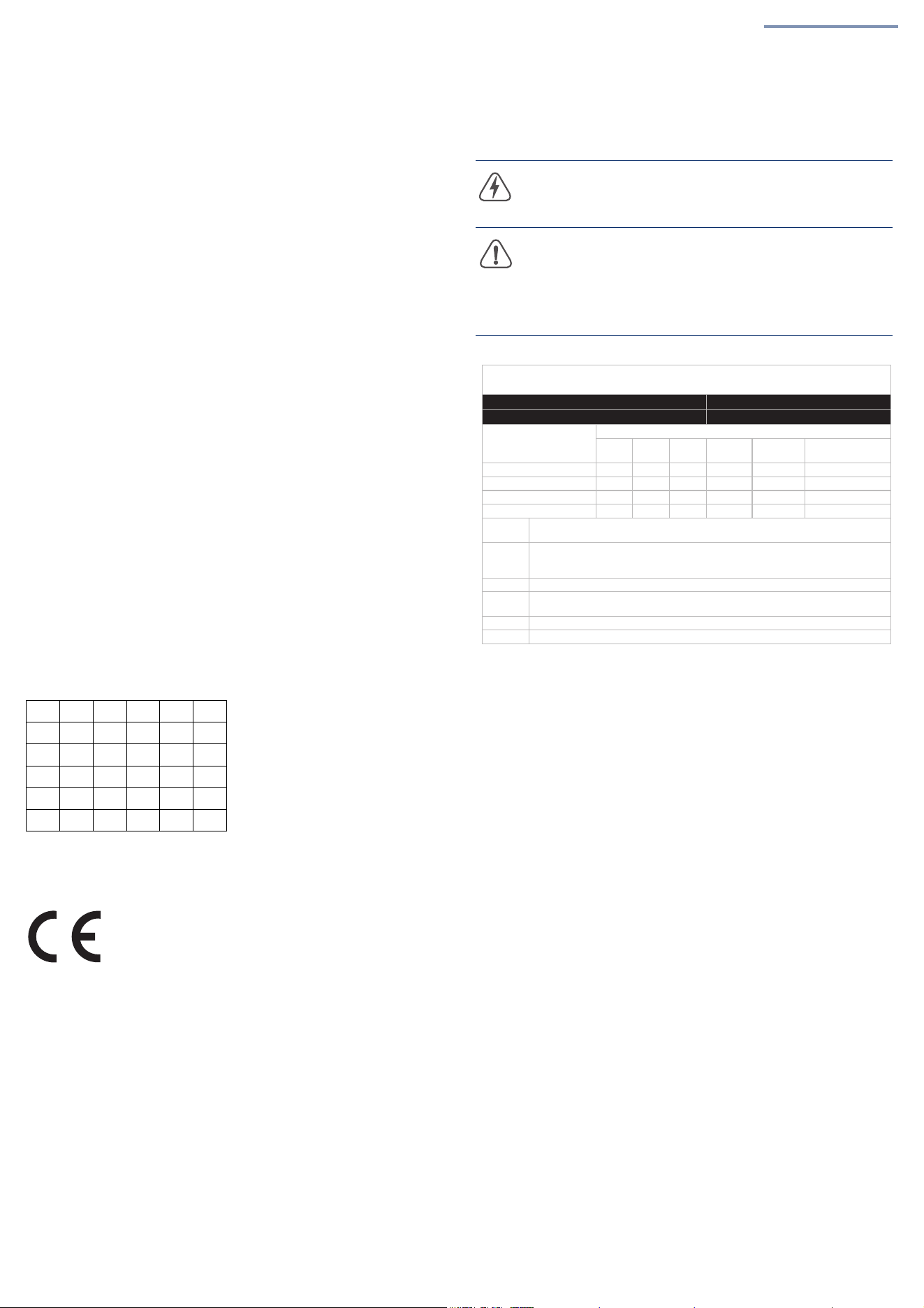
AT BE BG CH CY CZ
DE DK EE EL ES FI
FR HR HU IE IS IT
LI LT LU LV MT NL
NO PL PT RO SE SI
SK TR UK
Warning:
This product does not contain any serviceable user
parts.
Warning:
Installation and removal of the unit must be carried
out by qualified personnel only.
Caution:
Wear an anti-static wrist strap or take other suitable
measures to prevent electrostatic discharge when handling this
equipment.
Caution:
Do not plug a phone jack connector in the RJ-45
port. This may damage this device.
Caution:
Use only twisted-pair cables with RJ-45 connectors
that conform to FCC standards.
攎䏦䄧宨⋩㗇⾃㭿㣗䟸估㓌㖶
'HFODUDWLRQRIWKH3UHVHQFH&RQGLWLRQRIWKH5HVWULFWHG6XEVWDQFHV0DUNLQJ
娔₀⏴䨘Ɲ䄈䷁㎌⎽♏ :L)L$FFHVV3RLQW
❲噆 ❲ Ɲ($3V
(TXLSPHQW1DPH 7\SH'HVLJQDWLRQ7\SH
▕K8QLW
昷䔏䉐峑⎱⅝⋽⭟䬍噆5HVWULFWHGVXEVWDQFHVDQGLWVFKHPLFDOV\PEROV
扂
3E
㱅
+J
捿
&G
⅔扢
&U
⤁㺛偖勖
3%%
⤁㺛ṳ勖憁
3%'(
曢巖㝦䴫ờ 3&%$ £ ĉ ĉ ĉ ĉ ĉ
㩆㮣 &KDVVLV £ ĉ ĉ ĉ ĉ ĉ
⤐䷁$QWHQQD £ ĉ ĉ ĉ ĉ ĉ
愴ờ $FFHVVRULHV ĉ ĉ ĉ ĉ ĉ ĉ
₀ 俪 嵬⇡ZW⎱嵬⇡ZWᾩ㋮昷䔏䉐峑Ḳ䙥⇭㮻␒憶嵬⇡䙥⇭㮻␒憶⟡㹽
‣˛
1 R W H ([FHHGLQJZWDQGH[FHHGLQJZWLQGLFDWHWKDWWKHSHUFHQWDJH
FRQWHQWRIWKHUHVWULFWHGVXEVWDQFHH[FHHGVWKHUHIHUHQFHSHUFHQWDJHYDOXHRI
SUHVHQFHFRQGLWLRQ
₀ 俪 ĉ ᾩ㋮婙柬昷䔏䉐峑Ḳ䙥⇭㮻␒憶㜑嵬⇡䙥⇭㮻␒憶⟡㹽‣˛
1 R W H ĉ LQGLFDWHVWKDWWKHSHUFHQWDJHFRQWHQWRIWKHUHVWULFWHGVXEVWDQFHGRHVQRW
H[FHHGWKHSHUFHQWDJHRIUHIHUHQFHYDOXHRISUHVHQFH
₀ 俪 £ ᾩ㋮婙柬昷䔏䉐峑䂡㍹晋柬䛕˛
1 R W H 7KH £ LQGLFDWHVWKDWWKHUHVWULFWHGVXEVWDQFHFRUUHVSRQGVWRWKHH[HPSWLRQ

Quick Start Guide
– 5 –
Hardware Specifications
AP Chassis
Size (WxDxH) 195 x 179 x 35 mm (7.48 x 7.05 x 1.38 in.)
Weight 0.907 kg (1.99 lb)
Temperature Operating: 0° C to 50° C (32° F to 122° F)
Storage: -30° C to 70° C (-22° F to 158° F)
Humidity Operating: 5% to 95% (non-condensing)
Waterproof Rating IP41
Network Interfaces and Ports
Ports Uplink Port: 1× 5GBASE-T RJ-45 (PoE PD)
Console Port: RJ-45 (RS-232)
2.4 GHz Radio IEEE 802.11b/g/n/ax/be
5 GHz Radio IEEE 802.11a/ac/n/ax/be
6 GHz Radio IEEE 802.11a/ac/n/ax/be
Bluetooth Radio IEEE 802.15.1
Radio Frequencies 2.400–2.4835 GHz (ISM)
5.150–5.250 GHz (U-NII-1)
5.250–5.350 GHz (U-NII-2A)
5.470–5.725 GHz (U-NII-2C/U-NII-2E)
5.725–5.850 GHz (U-NII-3)
5.945–6.425 GHz (U-NII-5)
6.425–6.525 GHz (U-NII-6)
6.525–6.875 GHz (U-NII-7)
6.875–7.125 GHz (U-NII-8)
Power Specifications
PoE Input Power 25.5 W, 42.5–57 VDC, 0.6 A max., 802.3at
compliant
DC Input Power DC in, 12 V 3 A max.
Regulatory Compliances
Radio EN300 328 V2.2.2 (2019-07)
EN301 893 V2.2.1 (2024-11)
ETSI EN 303 687 V1.1.1
47 CFR FCC Part 15.247
47 CFR FCC Part 15.407
IC RSS-247 Issue 3, RSS-248 Issue 3, and RSS-
Gen Issue 5
NCC LP002 Section 4.10.1 (2024-02-06)
NCC LP002 Section 5.7 (2024-02-06)
NCC LP002 Section 5.13 (2024-02-06)
Emissions EN 55032:2015/A1:2020 Class B
EN 55035:2017/A11:2020
EN 301 489-1 V2.2.3
EN 301 489-17 V3.3.1
AS/NZS CISPR 32:2015, Class B
47 CFR FCC Rules and Regulations Part 15
Subpart B, Class B Digital Device
ICES-003, Issue 7 Class B
CNS 15936 Class B
Safety Low Voltage Directive IEC 62368-1:2018;and/or
EN IEC 62368-1:2020+A11:2020; and/or
BS EN 62368-1:2020+A11:2020
CNS 15598-1:2020
Taiwan RoHS CNS 15663