Serial Number
SG24184
Purchase Date
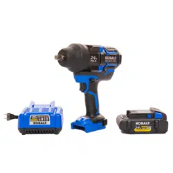
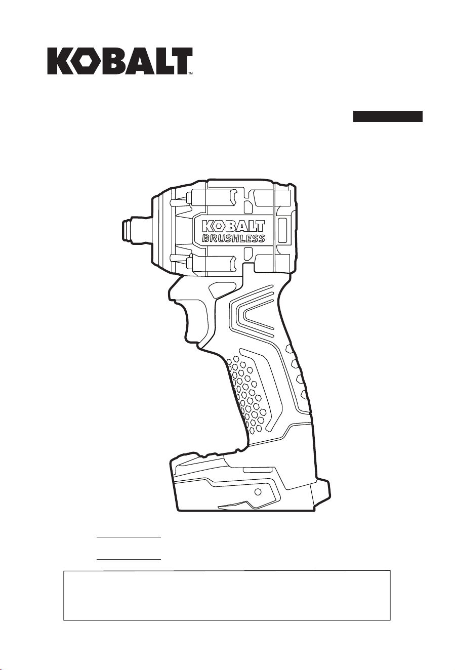
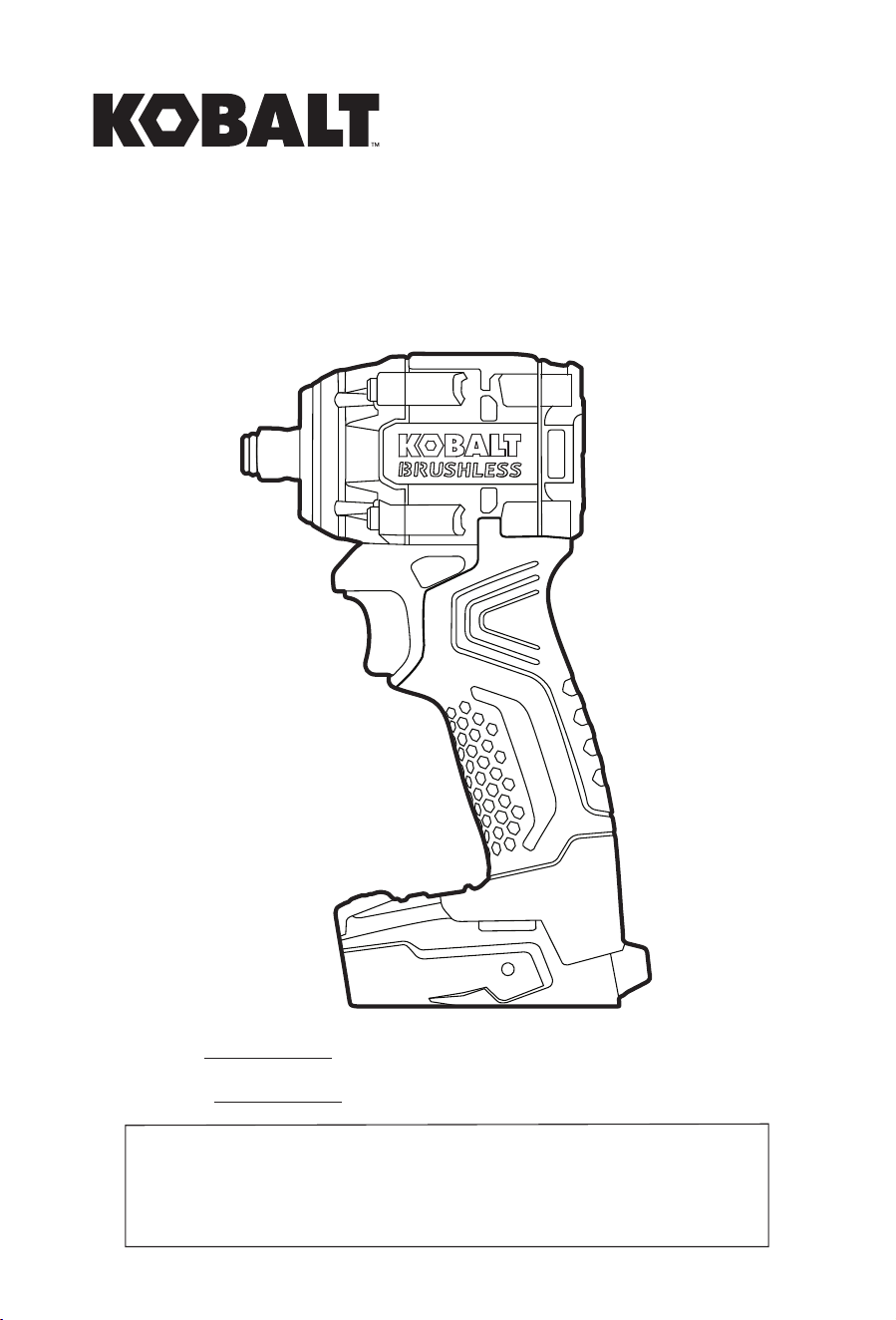
ITEM #5645469
MODEL #KCIW 224B-03
1/2 IN COMPACT
IMPACT WRENCH
Español p. 15
ATTACH YOUR RECEIPT HERE
Thank you for purchasing this KOBALT product.
Questions, problems or missing parts?
Before returning, contact us on: 888-3KOBALT (888-356-2258), 8 a.m.-8 p.m.,
EST, Monday - Sunday or [email protected].
KOBALT and logo design are trademarks or
registered trademarks of LF, LLC. All rights
reserved.

2
TABLE OF CONTENTS
Package Contents ........................................................................................................................... 3
Hardware Contents.......................................................................................................................... 4
Safety Information ........................................................................................................................... 4
Preparation ...................................................................................................................................... 8
Assembly Instructions...................................................................................................................... 8
Operating Instructions ..................................................................................................................... 9
Care and Maintenance .................................................................................................................. 13
Troubleshooting ............................................................................................................................. 14
Warranty ........................................................................................................................................ 14
PRODUCT SPECIFICATIONS
COMPONENT SPECIFICATIONS
Rated Voltage
24 V
No-load Speed (n
0
) 0-800/0-1200/0-2500 /min (RPM)
Anvil size 1/2” square
Maximum torque 250 ft. lbs. when tightening
275 ft. lbs. when loosening
Impact rate 0-900/0-1600/0-3400 IPM
Recommended Operating and Storage
Temperature
41°F (5°C) - 104°F (40°C)
3
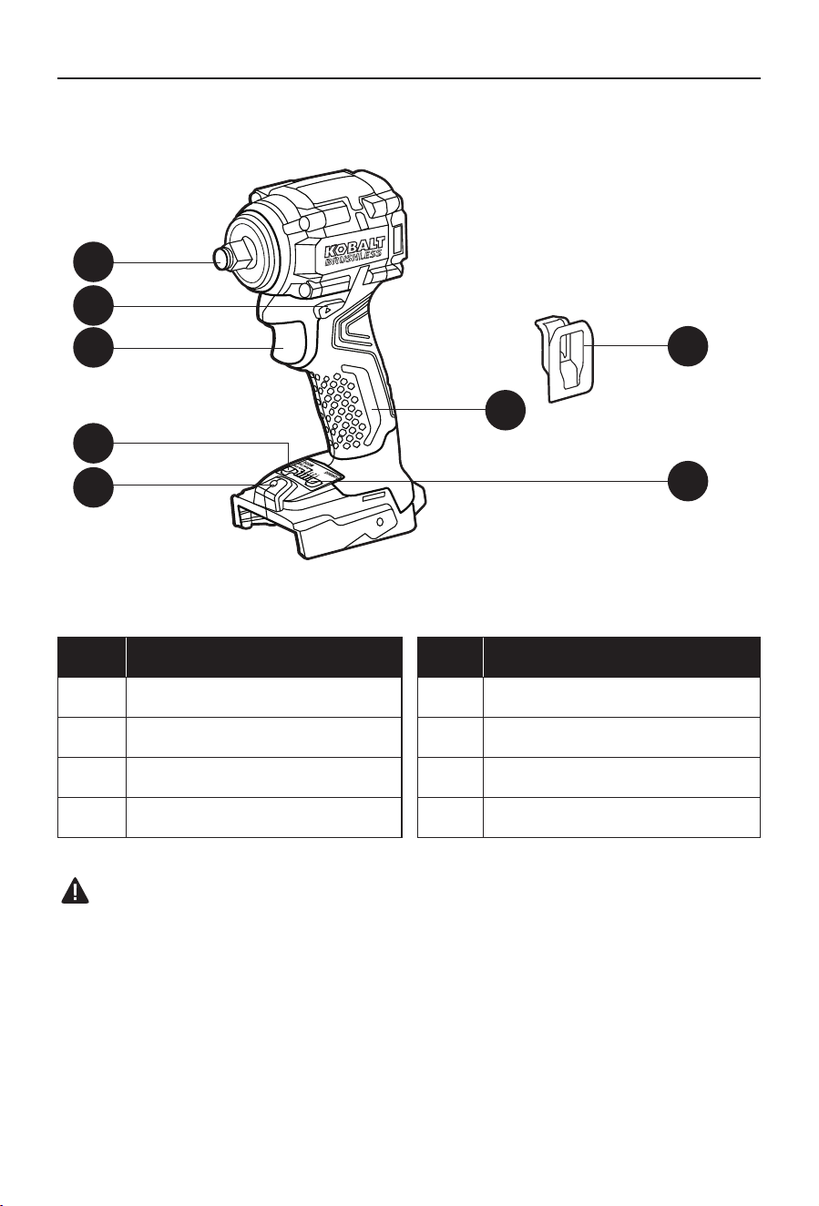
PACKAGE CONTENTS
F
E
D
G
H
C
B
A
PART DESCRIPTION PART DESCRIPTION
A Anvil E Mode button
B Direction-of-rotation selector F LED work light
C Variable-speed trigger switch G Torque/Speed button
D Handle H Belt clip
WARNING:
• Remove the tool from the package and examine it carefully. Do not discard the carton or any
packaging material until all parts have been examined.
• If any part of the tool is missing or damaged, do not attach the battery pack or use the tool until
the part has been repaired or replaced. Failure to heed this warning could result in serious
injury.
4
HARDWARE CONTENTS
SAFETY INFORMATION
Please read and understand this entire manual before attempting to assemble, operate or install
the product.
WARNING:
• The operation of any power tool can result in foreign objects being thrown into your eyes,
which can result in severe eye damage. Before beginning power-tool operation, always wear
safety goggles or safety glasses with side shields and a full-face shield, when needed. We
recommend using a wide vision safety mask over eyeglasses or standard safety glasses with
shields. Always use eye protection marked to comply with ANSI Z87.1.
WARNING:
• Drilling, sawing, sanding or machining wood products can expose you to wood dust, a
substance known to the State of California to cause cancer. Avoid inhaling wood dust or use a
dust mask or other safeguards for personal protection. For more information go to
www.P65Warnings.ca.gov/wood.
WARNING:
• Some dust created by power sanding, sawing, grinding, drilling and other construction activities
contains chemicals known to the state of California to cause cancer, birth defects or other
reproductive harm. Some examples of these chemicals are:
– Lead from lead-based paints,
– Crystalline silica from bricks and cement and other masonry products, and
– Arsenic and chromium from chemically-treated lumber.
Your risk from these exposures varies, depending on how often you do this type of work.
To reduce your exposure to these chemicals: work in a well ventilated area, and work with
approved safety equipment, such as those dust masks that are specially designed to lter out
microscopic particles.
M4 x 12 mm
Screw
Qty. 1
AA
5
SAFETY INFORMATION
Some of the following symbols may be used on this tool. Please study them and their meaning.
Proper interpretation of these symbols will allow you to operate the tool better and more safely.
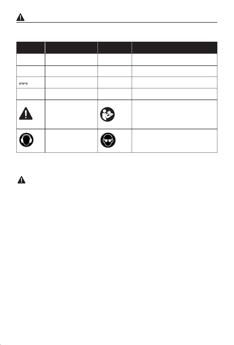
SYMBOL DEFINITION SYMBOL DEFINITION
V Volts n
0
No-load Speed
RPM Revolutions per Minute IPM Impacts per Minute
or d.c.
Direct Current …/min Revolutions or Strokes per
N m Newton Meter ft. lbs. Pound-foot
A danger, warning,
or caution. It means
‘Attention! Your safety
is involved.’
To reduce the risk of injury, user must
read instruction manual.
To reduce the risk of
injury, always wear ear
protection.
To reduce the risk of injury, always
wear eye protection.
General Power Tool Safety Warnings
WARNING:
• Read all safety warnings, instructions, illustrations and specications provided with this
power tool. Failure to follow all instructions listed below may result in electric shock, re and/or
serious injury.
Save all warnings and instructions for future reference
The term “power tool” in the warnings refers to your mains-operated (corded) power tool or
battery-operated (cordless) power tool.
Work Area Safety
• Keep work area clean and well lit. Cluttered or dark areas invite accidents.
• Do not operate power tools in explosive atmospheres, such as in the presence of
ammable liquids, gases or dust. Power tools create sparks which may ignite the dust or
fumes.
• Keep children and bystanders away while operating a power tool. Distractions can cause
you to lose control.
Electrical Safety
• Power tool plugs must match the outlet. Never modify the plug in any way. Do not use
any adapter plugs with earthed (grounded) power tools. Unmodied plugs and matching
outlets will reduce risk of electric shock.

6
SAFETY INFORMATION
• Avoid body contact with earthed or grounded surfaces, such as pipes, radiators, ranges
and refrigerators. There is an increased risk of electric shock if your body is earthed or
grounded.
• Do not expose power tools to rain or wet conditions. Water entering a power tool will
increase the risk of electric shock.
• Do not abuse the cord. Never use the cord for carrying, pulling or unplugging the power
tool. Keep cord away from heat, oil, sharp edges or moving parts. Damaged or entangled
cords increase the risk of electric shock.
• When operating a power tool outdoors, use an extension cord suitable for outdoor use.
Use of a cord suitable for outdoor use reduces the risk of electric shock.
• If operating a power tool in a damp location is unavoidable, use a ground fault circuit
interrupter (GFCI) protected supply. Use of a GFCI reduces the risk of electric shock.
Personal Safety
• Stay alert, watch what you are doing and use common sense when operating a power
tool. Do not use a power tool while you are tired or under the inuence of drugs, alcohol
or medication. A moment of inattention while operating power tools may result in serious
personal injury.
• Use personal protective equipment. Always wear eye protection. Protective equipment
such as a dust mask, non-skid safety shoes, hard hat or hearing protection used for appropriate
conditions will reduce personal injuries.
• Prevent unintentional starting. Ensure the switch is in the off-position before connecting
to power source and/or battery pack, picking up or carrying the tool. Carrying power
tools with your nger on the switch or energising power tools that have the switch on invites
accidents.
• Remove any adjusting key or wrench before turning the power tool on. A wrench or a key
left attached to a rotating part of the power tool may result in personal injury.
• Do not overreach. Keep proper footing and balance at all times. This enables better control
of the power tool in unexpected situations.
• Dress properly. Do not wear loose clothing or jewelry. Keep your hair and clothing away
from moving parts. Loose clothes, jewelry or long hair can be caught in moving parts.
• If devices are provided for the connection of dust extraction and collection facilities,
ensure these are connected and properly used. Use of dust collection can reduce dust-
related hazards.
• Do not let familiarity gained from frequent use of tools allow you to become complacent
and ignore tool safety principles. A careless action can cause severe injury within a fraction
of a second.
Power tool use and care
• Do not force the power tool. Use the correct power tool for your application. The correct
power tool will do the job better and safer at the rate for which it was designed.
• Do not use the power tool if the switch does not turn it on and off. Any power tool that
cannot be controlled with the switch is dangerous and must be repaired.
• Disconnect the plug from the power source and/or remove the battery pack, if
detachable, from the power tool before making any adjustments, changing accessories,
or storing power tools. Such preventive safety measures reduce the risk of starting the power
tool accidentally.
• Store idle power tools out of the reach of children and do not allow persons unfamiliar
with the power tool or these instructions to operate the power tool. Power tools are
dangerous in the hands of untrained users.

7
SAFETY INFORMATION
• Maintain power tools and accessories. Check for misalignment or binding of moving
parts, breakage of parts and any other condition that may affect the power tool’s
operation. If damaged, have the power tool repaired before use. Many accidents are
caused by poorly maintained power tools.
• Keep cutting tools sharp and clean. Properly maintained cutting tools with sharp cutting
edges are less likely to bind and are easier to control.
• Use the power tool, accessories and tool bits etc. in accordance with these instructions,
taking into account the working conditions and the work to be performed. Use of the
power tool for operations different from those intended could result in a hazardous situation.
• Keep handles and grasping surfaces dry, clean and free from oil and grease. Slippery
handles and grasping surfaces do not allow for safe handling and control of the tool in
unexpected situations.
Battery Tool Use and Care
• Recharge only with the charger specied by the manufacturer. A charger that is suitable for
one type of battery pack may create a risk of re when used with another battery pack.
• Use power tools only with specically designated battery packs. Use of any other battery
packs may create a risk of injury and re.
• When battery pack is not in use, keep it away from other metal objects, like paper clips,
coins, keys, nails, screws or other small metal objects, that can make a connection from
one terminal to another. Shorting the battery terminals together may cause burns or a re.
• Under abusive conditions, liquid may be ejected from the battery; avoid contact. If
contact accidentally occurs, ush with water. If liquid contacts eyes, additionally seek
medical help. Liquid ejected from the battery may cause irritation or burns.
• Do not use a battery pack or tool that is damaged or modied. Damaged or modied
batteries may exhibit unpredictable behavior resulting in re, explosion or risk of injury.
• Do not expose a battery pack or tool to re or excessive temperature. Exposure to re or
temperature above 265 °F (130 °C) may cause explosion.
• Follow all charging instructions and do not charge the battery pack or tool outside the
temperature range specied in the instructions. Charging improperly or at temperatures
outside the specied range may damage the battery and increase the risk of re.
Service
• Have your power tool serviced by a qualied repair person using only identical
replacement parts. This will ensure that the safety of the power tool is maintained.
• Never service damaged battery packs. Service of battery packs should only be performed by
the manufacturer or authorized service providers.
Specic Safety Warnings for Impact Wrench
• Hold the power tool by insulated gripping surfaces, when performing an operation
where the fastener may contact hidden wiring. Fasteners contacting a “live” wire may make
exposed metal parts of the power tool “live” and could give the operator an electric shock.
8
SAFETY INFORMATION
Additional Warnings
• Use only with the battery packs and chargers listed below:
BATTERY PACK BATTERY CHARGER
KB 224-03; KB 424-03; KB 524-03;
KB 624-03; KXB 424-03; KXB 824-03;
KRC 2445-03; KRC 2490-03; KRC 2404-03;
KDPC 124-03; KCH 2401-03; KCH 2411-03;
• The battery pack and charger manuals are provided separately. They include specic
safety rules and operating instructions. Please refer to the battery pack and charger
manuals for safety rules and detailed operating instructions.
PREPARATION
Before beginning assembly of product, make sure all parts are present. Compare parts with
package contents list and hardware contents list. If any part is missing or damaged, do not
attempt to assemble the product.
Tools Required for Assembly (not included): Phillips Screwdriver
WARNING:
• Do not allow familiarity with the impact wrench to cause carelessness. Remember that one
careless moment is enough to cause severe injury. Before attempting to use any tool, be sure
to become familiar with all of the operating features and safety instructions.
• Do not attempt to modify this tool or create accessories not recommended for use with this tool.
Any such alteration or modication is misuse and could result in a hazardous condition leading
to possible serious personal injury.
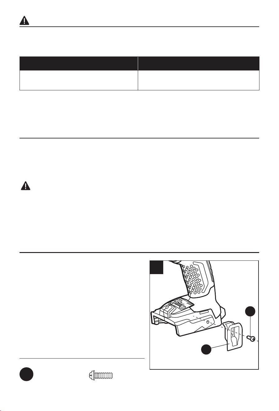
ASSEMBLY INSTRUCTIONS
H
1
TT
AA
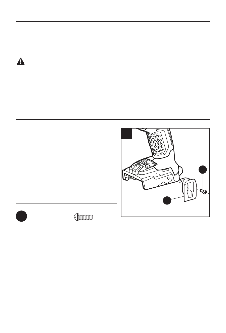
1. Installing and Removing the Belt Clip
a. Remove the battery pack from the tool.
b. Align the rib of the belt clip (H) with the hole on
the base of the wrench.
c. Insert the screw (AA) and tighten the screw
securely with a Phillips screwdriver (not
included).
d. To remove the belt clip, use a Phillips
screwdriver to loosen the screw and remove the
belt clip.
Hardware Used
AA
M4 x 12 mm Screw x 1
9
OPERATING INSTRUCTIONS
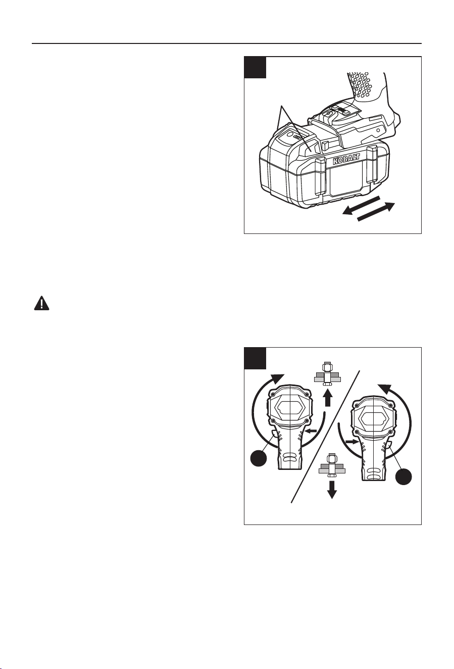
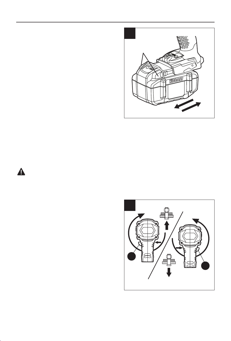
2. To Attach Battery Pack
a. Align the raised portion on the battery pack with
the grooves on the bottom of the tool, and then
slide the battery pack onto the tool as shown.
b. Make sure that the latch on the battery pack
snaps into place and the battery pack is secured
to the tool before beginning operation.
NOTICE: When placing the battery pack on the
tool, be sure that the raised rib on battery pack
aligns with the groove on the tool and the latches
snap into place properly. Improper assembly of
the battery pack can cause damage to internal
components.
To Detach Battery Pack
a. Press the battery-release buttons to release the battery pack.
b. Pull the battery pack backward to remove it from the tool.
WARNING:
• Battery tools are always in operating condition. Therefore, always remove the battery pack
when the tool is not in use or when carrying the tool at your side.
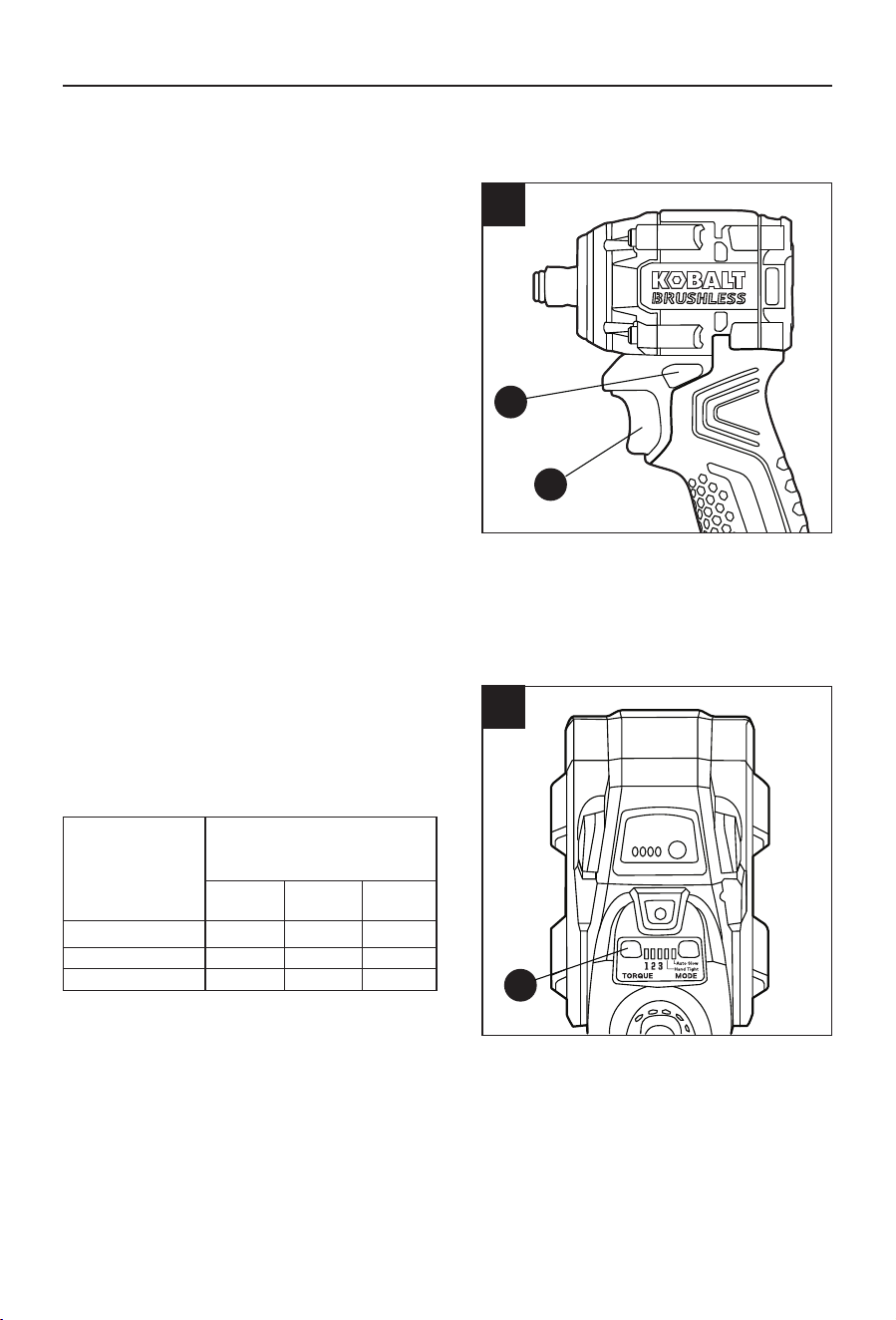
3. Direction-of-Rotation Selector
(Forward/Center Lock/Reverse)
The direction of rotation is reversible and is
controlled by the direction-of-rotation selector
(B) located above the trigger switch (C). With
the impact wrench held in the normal operating
position, pointing away from you:
a. Position the direction-of-rotation selector (B) to
the left of the tool for forward rotation to tighten
the bolts.
b. Position the direction-of-rotation selector (B) to
the right of the tool for reverse rotation to loosen
the bolts.
c. Setting the selector in the center position locks
the trigger to helps reduce the possibility of
accidental starting when the tool is not in use.
NOTICE:
• To prevent gear damage, always allow the impact wrench to come to a complete stop before
changing the direction of rotation.
• The impact wrench will not run unless the direction-of-rotation selector (B) is engaged fully to
the left or right.
2
Battery-release
buttons
B
B
Forward
Reverse
3
10
OPERATING INSTRUCTIONS
4. Variable-speed Trigger Switch
a. Position the direction-of-rotation selector (B) to
the left or right of the tool as needed to unlock
the trigger switch (C).
b. To turn the impact wrench ON, depress the
trigger switch (C).
c. To turn it OFF, release the trigger switch (C).
Variable Speed
The variable-speed trigger switch (C) delivers
higher speed with increased trigger pressure and
lower speed with decreased trigger pressure.
Electric Brake
The compact impact wrench is equipped with an electric brake. When the trigger switch is
released, the electric brake engages automatically to quickly stop rotation.
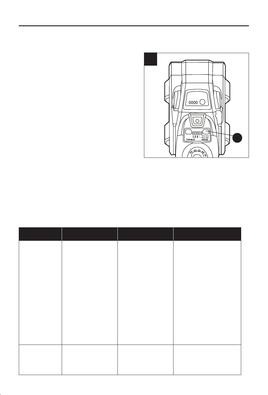
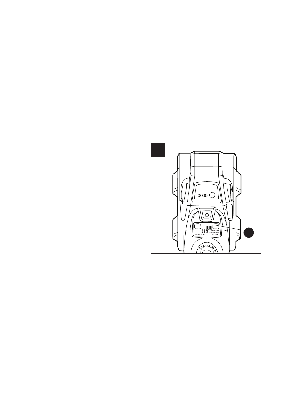
5. Torque/Speed Range Selection
The impact wrench features a torque/speed button
(G), located on the base of the tool, to select among
three different variable torque/speed ranges:
No load Speed,
Impact rate, and
Torque
Torque/Speed Range
1 2 3
/min (RPM) 0-800 0-1200 0-2500
IPM 0-900 0-1600 0-3400
ft. lbs. 75 150 250
To engage the torque/speed setting:
a. Attach the battery pack to the tool.
b. Position the direction-of-rotation selector (B) to
the left or right of the tool.
c. Depress and release the variable-speed trigger switch (C) to “wake up” the control panel.
d. Press the torque/speed button (G) to set the range. Every press of the button switches the
torque/speed to the next range.
NOTE:
• The higher the set range, the more torque the impact wrench produces to turn a fastener.
The proper setting depends on the job, the bit type, fastener, and material you are using.
• Indicator light above “1” is on – the impact wrench provides lowest speed and torque.
Indicator lights above “1” and “2” are on – the impact wrench provides medium speed and
torque. Indicator lights above “1”, “2”, and “3” are on – the impact wrench provides maximum
speed and torque.
• The indicator lights will turn off within approximately 1 min after the variable-speed trigger
switch or torque/speed button is released, and will return to the last used setting when the tool
is turned on again.
B
C
4
G
5
11
OPERATING INSTRUCTIONS
• Do not change the torque/speed setting when the tool is running. The torque/speed range will
not change until you release the variable-speed trigger switch.
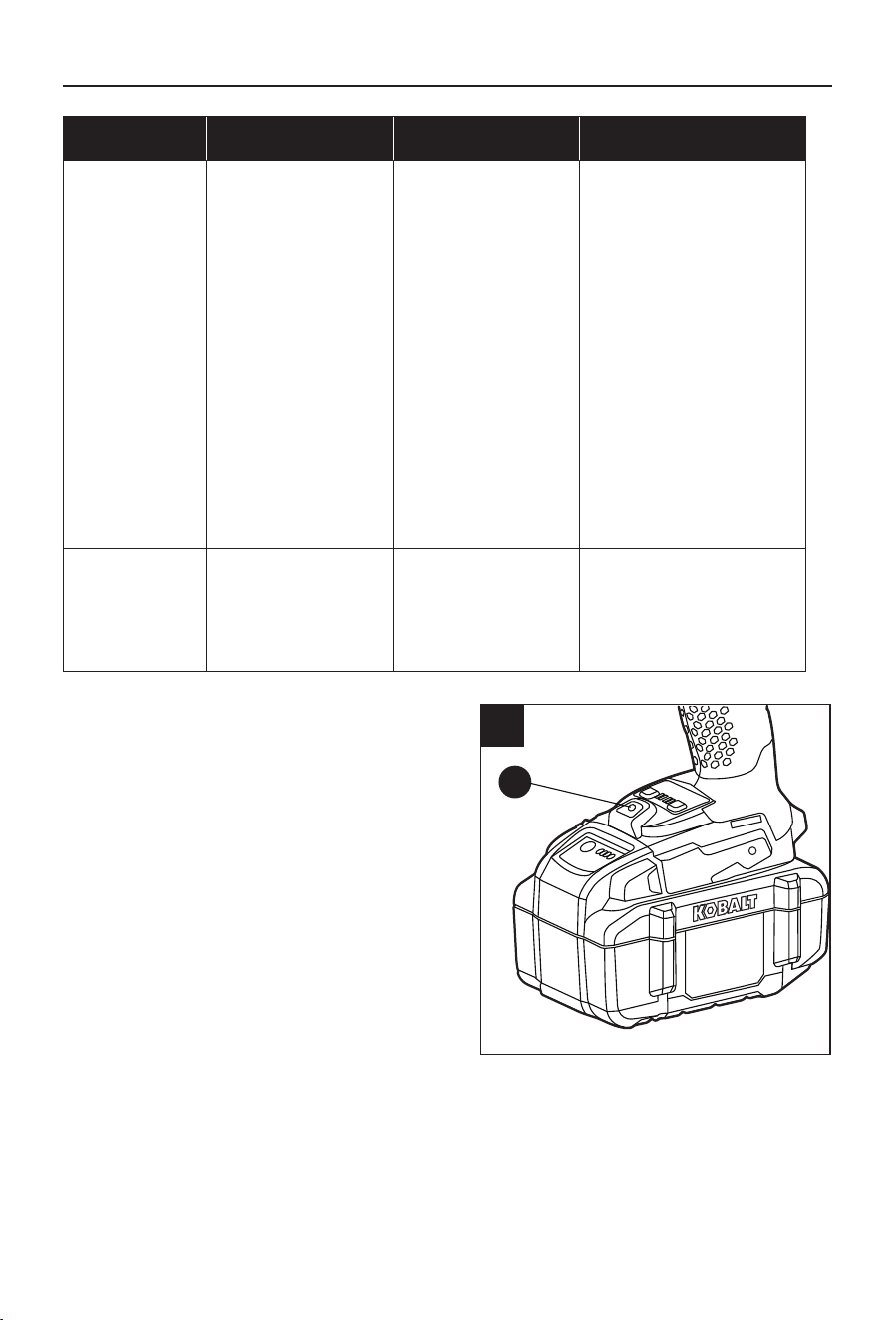
6. Mode Selection
This tool features two modes: “Auto Slow “and
“Hand Tight”. The mode button (E) is located on the
base of the tool. You can nd details in the table
below.
To engage the “Auto Slow” or “Hand Tight” mode:
a. Attach the battery pack to the tool.
b. “Hand Tight” mode only works when the tool is
in the forward rotation. Position the direction-
of-rotation selector (B) to the left of the tool for
forward rotation.
“Auto Slow” mode only works when the tool is
in the reverse rotation. Position the direction-
of-rotation selector (B) to the right of the tool for
reverse rotation.
c. Depress and release the variable-speed trigger
switch (C) to “wake up” the control panel.
d. Press the mode button (E) to select the mode. Every time you press the mode button, the mode
will be switched on/off. The green indicator light above the corresponding mode will illuminate
to indicate that it is activated.
NOTICE:
• The LED indicator light will turn off within approximately 1 min after the variable-speed trigger
switch or mode button is released, and will return to the last used setting when the tool is turned
on again.
MODE APPLICATION FEATURE FUNCTION
“Hand Tight”
Tightening car wheel
lug nuts which will
later be checked/
tightened with a
torque wrench.
OR
Driving bolt/nut
into the workpiece
when the surface
appearance is
important.
The tool will stop
rotating soon after
impact mechanism is
engaged.
This mode allows the user
to work fast with precision
while not damaging the
workpiece.
It helps to prevent over-
tightening of the bolt/
nut and damage to the
workpiece surface.
NOTE: The timing to
stop the driving varies
depending on the type of
the bolt/nut and material
to be driven in. Perform a
test driving before using
this mode.
“Auto Slow”
Removing bolt/nut
from the workpiece
in a controlled
manner.
The tool will slow
down the speed as
soon as the bolt/nut
is loose.
This mode helps to
prevent the bolt/nut from
falling or being thrown out
of the socket.
E
6
12
OPERATING INSTRUCTIONS
7. LED Work Light
The LED work light (F), located on the base of the
impact wrench, will illuminate when the variable-
speed trigger switch (C) is depressed. This
provides additional illumination of the surface of the
workpiece.
The LED work light will turn off after approximately
10 seconds after the variable-speed trigger switch
is released.
NOTE: The LED work light will ash in following
situations:
a. The LED work light will ash rapidly if the tool
has stopped working in order to protect internal
electronics; wait for the tool to cool down, at
which point in can be started again.
b. The LED work light will ash slowly to indicate that the battery pack charge is very low. Please
recharge the battery pack.
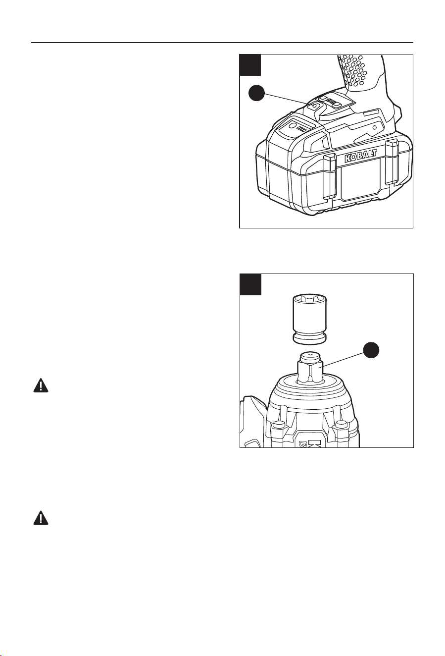
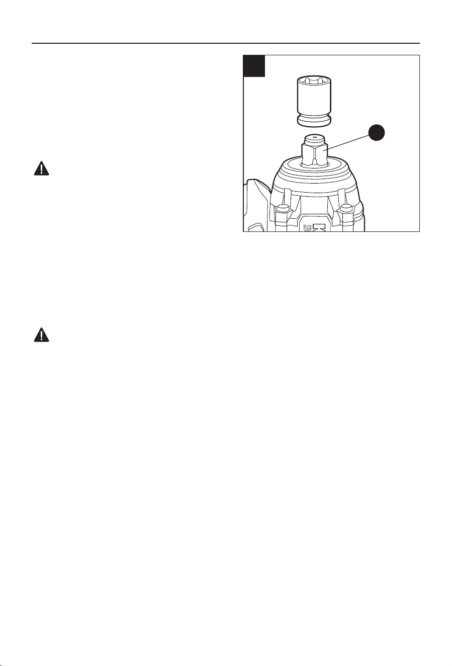
8. Installing and Removing a Socket
a. Place the direction-of-rotation selector (B) in the
center (lock) position.
b. To install a 1/2 in. socket (not included), simply
push the socket completely onto the square anvil
(A).
c. To remove the socket, pull it off.
WARNING:
• Only use sockets designed for impact wrenches.
Sockets not designed for impact wrenches could
break and result in user injury. Inspect sockets
prior to use to ensure that they have no cracks or
other visible damage.
• The socket may be hot after prolonged use. Use
protective gloves when removing the socket from the tool, or rst allow it to cool.
9. Tightening Fasteners with the Impact Wrench
WARNING:
• Battery tools are always in operating condition. Therefore, the direction-of-rotation selector (B)
should always be locked when not in use or carrying at your side.
NOTICE: The proper tightening torque may differ depending on the type or size of the bolt, the
material of the workpiece to be tightened, etc. Before starting your job, always perform a test
operation to determine the proper tightening time for your bolt or nut.
a. Check the direction-of-rotation selector (B) for the correct setting (forward or reverse).
b. Select the mode as necessary according to the application.
F
7
A
8

13
OPERATING INSTRUCTIONS
c. Select the suitable speed and torque range for the application. It is advisable to perform a trial
driving on a scrap material to determine the selection.
d. Hold the tool rmly and place the socket over the bolt or nut.
e. Depress the variable-speed trigger switch (C) to turn the impact wrench on. The variable speed
trigger switch delivers higher speed with increased trigger pressure and lower speed with
decreased trigger pressure.
f. Tighten the bolt or nut to the proper torque.
g. To turn the impact wrench OFF, release the variable-speed trigger switch (C).
h. After tightening, always check the torque with a torque wrench.
NOTICE:
• Hold the tool straight along the axis of the bolt or nut.
• Excessive tightening torque may damage the bolt/nut or socket.
Practice with various fasteners, noting the length of time required to reach the desired torque.
Check the tightness with a torque wrench. If the fasteners are too tight, reduce the impacting time.
If they are not tight enough, increase the impacting time.
The tightening torque is affected by a wide variety of factors, including the following:
• Socket
– Failure to use the correct size socket will cause a reduction in the tightening torque. A worn
socket (wear on the hex end or square end) will cause a reduction in the tightening torque.
• Bolt
– Although the torque coefcient and the class of bolt may be the same, the proper tightening
torque will differ according to the diameter of the bolt. Although the diameters of bolts may be
the same, the proper tightening torque will differ according to the torque coefcient, the class
of bolt and the bolt length.
• The use of a universal joint or an extension bar (both sold separately) will reduce the tightening
force of the impact wrench somewhat. Compensate by tightening for a longer period of time.
• The manner of holding the tool or the material to be fastened will affect the torque.
Loosening Fasteners
The torque that is required to loosen a fastener averages 75% to 80% of the tightening torque,
depending on the condition of the contacting surfaces. However, if rust or corrosion causes
seizing, more torque may be required.
CARE AND MAINTENANCE
WARNING: All maintenance should only be carried out by a qualied service technician.
Cleaning
WARNING: Before cleaning or performing any maintenance, remove the battery pack from
the tool. For safe and proper operation, always keep the tool and its ventilation slots clean.
Always use only a soft, dry cloth to clean your impact wrench; never use detergent or alcohol.

14
TROUBLESHOOTING
WARNING:
• Set the direction-of-rotation selector (B) in the center lock position and detach the battery pack
from the impact wrench before performing troubleshooting procedures.
PROBLEM POSSIBLE CAUSE CORRECTIVE ACTION
The impact wrench
does start or stops
unexpectedly.
Battery pack charge is depleted. Charge the battery pack.
The socket cannot be
installed.
The socket is of wrong size. Use a correct socket that ts
1/2" square anvil.
Motor overheating. Ventilation slots are obstructed. Clean and clear the ventilation
slots. Do not cover the
ventilation slots with hand
during operation.
The LED work light
ashes rapidly.
The tool has stopped working to
protect internal electronics.
Release the trigger switch,
wait for the tool to cool down,
and then start the tool again.
The LED work light
ashes slowly.
The battery pack charge is very low. Charge the battery pack.
WARRANTY
For 5 years from the date of purchase, the power tool is warranted and for 3 years from date of
purchase the battery & charger are warranted for the original purchaser to be free from defects
in material and workmanship. This guarantee does not cover damage due to abuse, normal
wear, improper maintenance, neglect, unauthorized repair/alteration, or expendable parts and
accessories expected to become unusable after a reasonable period of use. This warranty is
limited to 90 days for commercial and rental use.
If you think your product meets the above guarantee criteria, please return it to the place of
purchase with valid proof of purchase and the defective product will be repaired or replaced at no
charge. This guarantee gives you specic legal rights, and you may also have other rights that
vary from state to state.
If you have any questions regarding the product, please call customer service at
888-3KOBALT (888-356-2258) , 8 a.m. - 8 p.m., EST, Monday - Sunday. You could also contact us
Lowe’s Home Centers LLC.
MOORESVILLE, NC 28117
Printed in Vietnam
Número de serie
Fecha de compra
ARTÍCULO #5645469
MODELO #KCIW 224B-03
LLAVE DE PERCUSIÓN
COMPACTA DE 1/2
PULG.
ADJUNTE SU RECIBO AQUÍ
Gracias por comprar este producto KOBALT.
¿Preguntas, problemas o piezas faltantes?
Antes de hacer una devolución, contáctenos en: 888-3KOBALT (888-356-2258),
de 8 a.m. a 8 p.m., hora estándar del Este, de lunes a domingo o en
KOBALT y el diseño del logotipo son
marcas comerciales o marcas registradas
de LF, LLC. Todos los derechos reservados.

16
ÍNDICE
Contenido del paquete .................................................................................................................. 17
Aditamentos................................................................................................................................... 18
Información de seguridad .............................................................................................................. 18
Preparación ................................................................................................................................... 23
Instrucciones de ensamblaje ......................................................................................................... 23
Instrucciones de funcionamiento ................................................................................................... 24
Cuidado y mantenimiento .............................................................................................................. 29
Solución de problemas .................................................................................................................. 30
Garantía......................................................................................................................................... 30
ESPECIFICACIONES DEL PRODUCTO
COMPONENTE ESPECIFICACIONES
Rango de voltaje
24 V
Velocidad sin carga (n
0
) 0-800/0-1200/0-2500 /min (RPM)
Tamaño del yunque Cuadrado de 1/2"
Torsión máxima
250 pies-libras al ajustar
275 pies-libras al aojar
Clasicación de impacto 0-900/0-1600/0-3400 IPM
Temperatura recomendada de
funcionamiento y almacenamiento
De 5° C (41 °F) a 40 °C (104 °F)

17
CONTENIDO DEL PAQUETE
F
E
D
G
H
C
B
A
PIEZA DESCRIPCIÓN PIEZA DESCRIPCIÓN
A Yunque E Botón de modo
B Selector de dirección de rotación F Luz de trabajo LED
C
Interruptor tipo gatillo de velocidad
variable
G
Botón de par/velocidad
D
Manija
H
Presilla para cinturón
ADVERTENCIA:
• Retire la herramienta del paquete y examínela cuidadosamente. No deseche la caja ni ningún
material de embalaje hasta que no haya examinado todas las piezas.
• Si falta alguna pieza de la herramienta o si alguna pieza está dañada, no je el paquete de
baterías ni use la herramienta hasta reparar o reemplazar la pieza. El incumplimiento de esta
advertencia podría provocar lesiones graves.
18
ADITAMENTOS
INFORMACIÓN DE SEGURIDAD
Lea y comprenda completamente este manual antes de intentar ensamblar, usar o instalar el
producto.
ADVERTENCIA:
• La operación de cualquier herramienta eléctrica puede arrojar objetos extraños a los ojos y,
de esta manera, causar graves daños oculares. Use siempre lentes o gafas de seguridad con
protecciones laterales y, cuando sea necesario, un protector facial que cubra todo el rostro
antes de comenzar a operar una herramienta eléctrica. Recomendamos usar una máscara de
seguridad de visión amplia sobre los lentes o gafas de seguridad con protecciones estándar.
Siempre use lentes de protección que cumplan con la norma ANSI Z87.1.
ADVERTENCIA:
• Los productos para taladrar, aserrar, lijar o cortar madera pueden exponerlo al polvo de
madera, una sustancia reconocida por el estado de California como causante de cáncer. Evite
inhalar el polvo de la madera o utilice una mascarilla antipolvo u otros artículos de protección
personal. Para obtener más información, visite www.P65Warnings.ca.gov/wood.
ADVERTENCIA:
• Parte del polvo causado por el lijado eléctrico, el serruchado, la trituración, el taladro y otras
actividades de construcción contiene sustancias químicas que, según el estado de California,
causan cáncer, defectos congénitos u otros daños reproductivos. Estos son algunos ejemplos
de dichos productos químicos:
– Plomo presente en las pinturas con base de plomo,
– Sílice cristalina de ladrillos, cemento y otros productos de mampostería y
– Arsénico y cromo de madera tratada con químicos.
El riesgo que corre debido a la exposición a estos químicos varía según la frecuencia con que
la que se realiza este tipo de trabajo. Para reducir su exposición a estos productos químicos,
trabaje en un área bien ventilada y utilice un equipo de seguridad aprobado, como las
mascarillas antipolvo especialmente diseñadas para ltrar partículas microscópicas.
Tornillo
M4 x 12 mm
Cant. 1
AA
19
INFORMACIÓN DE SEGURIDAD
Algunos de los siguientes símbolos pueden aparecer en esta herramienta. Obsérvelos y aprenda
su signicado. La interpretación correcta de estos símbolos le permitirá utilizar la herramienta de
manera más ecaz y segura.
SÍMBOLO DEFINICIÓN SÍMBOLO DEFINICIÓN
V Voltios n
0
Velocidad sin carga
RPM Revoluciones por minuto IPM Impactos por minuto
o CC
Corriente continua …/min Revoluciones o pasadas por
N m Metro de Newton ft. lbs. Libra-pie
Peligro, advertencia o
precaución. Signica
"¡Atención! Su seguridad
está comprometida".
Para reducir el riesgo de lesiones,
el usuario debe leer el manual de
instrucciones.
Para reducir el riesgo de
lesiones, use siempre
la protección auditiva
adecuada.
Para reducir el riesgo de lesiones,
use siempre lentes de protección.
Advertencias generales de seguridad en el manejo de herramientas eléctricas
ADVERTENCIA:
• Lea todas las advertencias de seguridad, las instrucciones, las ilustraciones y las
especicaciones que se incluyen para esta herramienta eléctrica. No cumplir con todas las
instrucciones que se detallan a continuación podría provocar descargas eléctricas, incendios o
lesiones graves.
Guarde todas las advertencias e instrucciones para consultarlas más adelante.
El término “herramienta eléctrica” que aparece en las advertencias hace referencia a la
herramienta eléctrica que se conecta a la línea principal (con cable) o a la herramienta eléctrica
que funciona a batería (inalámbrica).
Seguridad en el área de trabajo
• Mantenga el área de trabajo limpia y bien iluminada. Las áreas desordenadas u oscuras
aumentan las posibilidades de accidentes.
• No utilice herramientas eléctricas en ambientes en los que exista un riesgo de
explosión, como por ejemplo, en presencia de líquidos inamables, gases o polvo. Las
herramientas eléctricas producen chispas que podrían encender el polvo o los gases.
• Mantenga a los niños y a otras personas alejados mientras utiliza una herramienta
eléctrica. Las distracciones pueden provocar que pierda el control.

20
INFORMACIÓN DE SEGURIDAD
Seguridad eléctrica
• Los enchufes de las herramientas eléctricas deben encajar en el tomacorriente.
Nunca modique el enchufe de ningún modo. No utilice ningún enchufe adaptador
con herramientas eléctricas (con puesta a tierra). Los enchufes sin modicaciones y que
encajan en los tomacorrientes reducen el riesgo de descargas eléctricas.
• Evite el contacto del cuerpo con supercies conectadas a tierra, como tuberías,
radiadores, extractores o refrigeradores. Si el cuerpo está en contacto con la tierra, corre
mayor riesgo de sufrir una descarga eléctrica.
• No exponga las herramientas eléctricas a la lluvia o a condiciones de humedad. Si
ingresa agua en una herramienta eléctrica, aumentará el riesgo de sufrir una descarga
eléctrica.
• No maltrate el cable. Nunca use el cable para transportar, jalar ni desenchufar la
herramienta eléctrica. Mantenga el cable alejado del calor, el aceite, los bordes losos o
las piezas en movimiento. Los cables dañados o enredados aumentan el riesgo de sufrir una
descarga eléctrica.
• Cuando utilice una herramienta eléctrica en exteriores, use una extensión eléctrica
adecuada para uso en exteriores. El uso de un cable apto para exteriores reduce el riesgo
de sufrir una descarga eléctrica.
• Si debe utilizar una herramienta eléctrica en un área húmeda, use un interruptor
de circuito de falla de puesta a tierra (GFCI, por sus siglas en inglés). Usar un GFCI
disminuye el riesgo de sufrir una descarga eléctrica.
Seguridad personal
• Manténgase alerta, preste atención a lo que hace y utilice el sentido común cuando
utilice una herramienta eléctrica. No utilice una herramienta eléctrica si está cansado o
bajo los efectos de drogas, alcohol o medicamentos. Un momento de desatención mientras
opera herramientas eléctricas puede provocar lesiones graves.
• Use un equipo de protección personal. Siempre use lentes de protección. Los equipos
de protección, como mascarillas antipolvo, zapatos de seguridad antideslizantes, cascos o
auriculares de seguridad, que se utilizan en las condiciones adecuadas disminuyen el riesgo
de sufrir lesiones.
• Evite un arranque accidental. Asegúrese de que el interruptor esté en la posición de
apagado antes de conectar la herramienta a la fuente de alimentación o al paquete de
baterías o antes de levantarla o transportarla. Transportar herramientas eléctricas con el
dedo en el interruptor o enchufar herramientas eléctricas que tienen el interruptor encendido
aumenta las posibilidades de sufrir accidentes.
• Retire todas las llaves de ajuste o llaves inglesas antes de encender la herramienta
eléctrica. Si se deja una llave inglesa o una llave conectada a una pieza giratoria de la
herramienta eléctrica, se pueden producir lesiones.
• No se extienda demasiado. Mantenga una postura rme y el equilibrio adecuado en
todo momento. Esto permite un mejor control de la herramienta eléctrica en situaciones
inesperadas.
• Use ropa adecuada. No use ropa holgada ni joyas. Mantenga el cabello y la ropa
alejados de las piezas en movimiento. La ropa holgada, las joyas o el cabello largo pueden
quedar atrapados en las piezas en movimiento.
• Si se proporcionan dispositivos para la conexión de instalaciones de extracción y
recolección de polvo, asegúrese de que se conecten y se usen de manera adecuada. La
recolección de polvo puede disminuir los peligros relacionados con este.

21
INFORMACIÓN DE SEGURIDAD
• No permita que la familiaridad del uso frecuente de las herramientas lo haga no tener en
cuenta los principios de seguridad en el manejo de las herramientas. Un descuido puede
ocasionar lesiones graves en cuestión de segundos.
Uso y cuidado de las herramientas eléctricas
• No fuerce la herramienta eléctrica. Utilice la herramienta eléctrica adecuada para su
aplicación. La herramienta eléctrica adecuada le permitirá realizar un trabajo de mejor calidad
y más seguro, al ritmo para el cual se diseñó.
• No utilice la herramienta eléctrica si el interruptor no la enciende o apaga. Cualquier
herramienta eléctrica que no pueda controlarse con el interruptor es peligrosa y debe
repararse.
• Desconecte el enchufe de la fuente de alimentación o retire el paquete de baterías, si
fuera posible, de la herramienta eléctrica antes de realizar cualquier ajuste, cambiar
accesorios o almacenar herramientas eléctricas. Estas medidas de seguridad preventivas
reducen el riesgo de provocar arranques accidentales de la herramienta eléctrica.
• Almacene las herramientas eléctricas que no estén en uso fuera del alcance de los
niños y no permita que personas que no conozcan cómo usar la herramienta o estas
instrucciones la utilicen. Las herramientas eléctricas son peligrosas en manos de usuarios
sin capacitación.
• Realice mantenimiento a las herramientas eléctricas y a los accesorios. Revise si
hay piezas móviles desalineadas o trabadas, si hay piezas rotas y cualquier otra
condición que pueda afectar el funcionamiento de la herramienta eléctrica. Si se daña la
herramienta eléctrica, hágala reparar antes de usarla. Muchos accidentes son producto del
mantenimiento incorrecto de las herramientas eléctricas.
• Mantenga las herramientas de corte aladas y limpias. Las herramientas de corte que se
mantienen de manera adecuada, con sus bordes de corte alados, corren menos riesgo de
trabarse y son más fáciles de controlar.
• Use la herramienta eléctrica, los accesorios, las brocas, etc. de acuerdo con estas
instrucciones y considere las condiciones de operación y el trabajo que desea realizar.
Si la herramienta eléctrica se usa en operaciones para las cuales no se diseñó, se podría
generar una situación peligrosa.
• Mantenga las manijas y las supercies de agarre secas, limpias y sin aceite ni grasa.
Las manijas y las supercies de agarre rresbaladizas no permiten manipular ni controlar la
herramienta de forma segura en situaciones inesperadas.
Uso y cuidado de herramientas a batería
• Recargue el paquete de baterías solo con el cargador especicado por el fabricante. Un
cargador adecuado para un tipo de paquete de baterías puede ocasionar riesgos de incendio
si se usa con otro paquete de baterías diferente.
• Use herramientas eléctricas solo con paquetes de baterías designados especícamente.
El uso de cualquier otro paquete de baterías puede generar un riesgo de lesión e incendio.
• Cuando no se use el paquete de baterías, aléjelo de objetos metálicos, como
sujetapapeles, monedas, llaves, clavos, tornillos u otros objetos metálicos pequeños
que pudieran crear una conexión entre los terminales. Si conecta los terminales de la
batería entre sí, es posible que se produzcan quemaduras o un incendio.
• En condiciones de maltrato, es posible que salga líquido de la batería. Evite el contacto.
Si se produce un contacto accidental, enjuague con agua. Si el líquido entra en contacto
con los ojos, solicite atención médica. El líquido que sale de la batería puede provocar
irritación o quemaduras.

22
INFORMACIÓN DE SEGURIDAD
• No utilice un paquete de baterías ni una herramienta si están dañadas o modicadas.
Las baterías dañadas o modicadas pueden tener reacciones impredecibles, que podrían
provocar incendios, explosiones o riesgo de lesiones.
• No exponga un paquete de baterías ni una herramienta al fuego ni a temperaturas
excesivas. La exposición al fuego o a temperaturas por encima de los 130 °C (265 °F) podría
causar una explosión.
• Siga todas las instrucciones de carga y no cargue el paquete de baterías ni la
herramienta fuera del rango de temperatura especicado en las instrucciones. La carga
inadecuada o a temperaturas fuera del rango especicado podría dañar la batería y aumentar
el riesgo de incendio.
Reparación
• Permita que solo una persona capacitada repare la herramienta eléctrica y que utilice
únicamente piezas de repuesto idénticas a las de fábrica. Esto garantizará la seguridad de
la herramienta eléctrica.
• Nunca realice el mantenimiento de los paquetes de baterías dañados. Solo el fabricante o
los proveedores de servicio autorizados pueden realizar el mantenimiento de los paquetes de
baterías.
Advertencias de seguridad especícas para la llave de percusión
• Si va a realizar una operación en la que el sujetador pudiera entrar en contacto con
cableados ocultos, sostenga las herramientas eléctricas por las supercies de agarre
aisladas. Es posible que los sujetadores que entren en contacto con un cable “energizado”
también “energicen” piezas de metal de la herramienta eléctrica y podrían provocar una
descarga eléctrica al operador.
Advertencias adicionales
• Use solamente los paquetes de baterías y los cargadores que se indican a continuación:
PAQUETE DE BATERÍAS CARGADOR DE BATERÍA
KB 224-03; KB 424-03; KB 524-03;
KB 624-03; KXB 424-03; KXB 824-03;
KRC 2445-03; KRC 2490-03; KRC 2404-03;
KDPC 124-03; KCH 2401-03; KCH 2411-03;
• Los manuales del paquete de baterías y del cargador se proporcionan por separado.
Incluyen normas de seguridad especícas e instrucciones de funcionamiento. Consulte
el manual del paquete de baterías y del cargador para conocer las reglas de seguridad y
las instrucciones detalladas de funcionamiento.
23
PREPARACIÓN
Antes de comenzar a ensamblar el producto, asegúrese de tener todas las piezas. Compare las
piezas con la lista del contenido del paquete y la lista de aditamentos. No intente ensamblar el
producto si falta alguna pieza o si están dañadas.
Herramientas necesarias para el ensamblaje (no se incluyen): destornillador Phillips
ADVERTENCIA:
• No permita que la familiaridad con la llave de percusión lo vuelva descuidado. Recuerde que
un momento de descuido es suciente para causar lesiones graves. Antes de intentar utilizar
una herramienta, asegúrese de familiarizarse con todas las funciones de funcionamiento e
instrucciones de seguridad.
• No intente modicar esta herramienta ni crear accesorios que no sean los recomendados
para esta. Toda alteración o modicación se considera un uso indebido y podría causar una
situación peligrosa que derive en lesiones graves.
INSTRUCCIONES DE ENSAMBLAJE
H
1
TT
AA
1. Instalación y retiro de la presilla para
cinturón
a. Retire el paquete de baterías de la herramienta.
b. Alinee la pestaña de la presilla para cinturón (H)
con el oricio en la base de la llave.
c. Inserte el tornillo (AA) y apriételo rmemente
con un destornillador Phillips (no se incluye).
d. Para retirar la presilla para cinturón, utilice un
destornillador Phillips para aojar el tornillo y
retirar la presilla.
Aditamentos utilizados
AA
Tornillo M4 x 12 mm x 1
24
INSTRUCCIONES DE FUNCIONAMIENTO
2. Cómo jar el paquete de baterías
a. Alinee la parte elevada del paquete de baterías
con las ranuras de la parte inferior de la
herramienta y luego deslice el paquete de
baterías hacia adentro de la herramienta, como
se muestra.
b. Asegúrese de que el pestillo del paquete de
baterías encaje en su lugar y que el paquete
de baterías esté jo en la herramienta antes de
comenzar la operación.
AVISO: cuando coloque el paquete de baterías
en la herramienta, asegúrese de que la varilla
elevada del paquete de baterías se alinee con la
ranura de la herramienta y que los pestillos encajen
en su lugar de manera correcta. El ensamblaje
inadecuado del paquete de baterías puede ocasionar daños en los componentes internos.
Para retirar el paquete de baterías, realice los siguientes pasos:
a. Presione los botones de liberación de la batería para poder retirar el paquete de baterías.
b. Jale el paquete de baterías hacia atrás para retirarlo de la herramienta.
ADVERTENCIA:
• Las herramientas con batería siempre están en condiciones de funcionamiento. Por lo tanto,
siempre retire el paquete de baterías cuando no use la herramienta o cuando la transporte
junto a usted.
3. Selector de dirección de rotación
(hacia delante/jación central/reversa)
La dirección de rotación es reversible y se controla
mediante el selector de dirección de rotación (B)
ubicado sobre el interruptor tipo gatillo (C). Con
la llave de percusión sostenida en la posición de
operación normal, apuntando en dirección opuesta
a usted:
a. Coloque el selector de dirección de rotación (B)
a la izquierda de la herramienta para que rote
hacia adelante a n de apretar los tornillos.
b. Coloque el selector de dirección de rotación (B)
a la derecha de la herramienta para que rote en
reverso a n de aojar los tornillos.
c. Fijar el selector en la posición de bloqueo
central bloquea el gatillo para ayuda a reducir la
posibilidad de arranque accidental cuando no se está utilizando la herramienta.
AVISO:
• para evitar el daño en las velocidades, siempre deje que la llave de percusión se detenga
completamente antes de cambiar la dirección de la rotación.
B
B
Avance
Reversa
3
2
Botones de liberación
de la batería
25
INSTRUCCIONES DE FUNCIONAMIENTO
• la llave de percusión no funciona a menos que el selector de dirección de rotación (B) esté
completamente posicionado a la izquierda o la derecha.
4. Interruptor tipo gatillo de velocidad variable
a. Coloque el selector de dirección de rotación (B)
a la izquierda o derecha de la herramienta según
sea necesario para desbloquear el interruptor
tipo gatillo (C).
b. Para ENCENDER la llave de percusión, presione
el interruptor tipo gatillo (C).
c. Para APAGARLO, suelte el interruptor tipo gatillo
(C).
Velocidad variable
El interruptor tipo gatillo de velocidad variable (C)
proporciona mayor velocidad con mayor presión en
el gatillo y menor velocidad con menor presión en
el gatillo.
Freno eléctrico
La llave de percusión compacta está equipada con un freno eléctrico. Al soltar el interruptor tipo
gatillo; se activará automáticamente el freno eléctrico para detener rápidamente la rotación.
5. Selección del rango de torsión/velocidad
La llave de percusión cuenta con un botón de
torsión/velocidad (G), situado en la base de la
herramienta, para seleccionar entre tres rangos
diferentes de torsión/velocidad variable:
Sin velocidad de
carga, tasa de
impacto y torsión
Para activar el ajuste de
torsión/velocidad:
1 2 3
/min (RPM) 0-800 0-1200 0-2500
IPM 0-900 0-1600 0-3400
pies-libras 75 150 250
Para activar el ajuste de torsión/velocidad:
a. Fije el paquete de baterías a la herramienta.
b. Coloque el selector de dirección de rotación (B) a la izquierda o la derecha de la herramienta.
c. Oprima y suelte el interruptor tipo gatillo de velocidad variable (C) para “despertar” el panel de
control.
d. Presione el botón de torsión/velocidad (G) para establecer la potencia. Cada pulsación del
botón de torsión/velocidad cambia la velocidad al siguiente rango.
B
C
4
G
5
26
INSTRUCCIONES DE FUNCIONAMIENTO
NOTA:
• Cuanto más alta sea la velocidad, mayor será la fuerza de torsión que producirá la llave de
percusión para girar un sujetador. La conguración correcta depende del trabajo, el tipo de
broca, el sujetador y el material que utilice.
• Si la luz indicadora que está por encima de “1” está encendida, la llave de percusión
proporcionará la velocidad y la torsión más bajas.
Si la luz indicadora que está por encima de “1” y “2” está encendida, la llave de percusión
proporciona velocidad media y torsión media. Si las luces indicadoras superiores a “1”, “2” y “3”
están encendidas, la llave de percusión proporciona velocidad y torsión máximas.
• La luces indicadoras se apagarán en aproximadamente un minuto después de que se suelte
el interruptor tipo gatillo de velocidad variable o botón de torsión/velocidad y volverán a la
conguración usada por última vez cuando la herramienta se vuelva a encender.
• No cambie la conguración de torsión/velocidad mientras la herramienta está en
funcionamiento. La gama de torsión/velocidades no cambiará hasta que suelte el interruptor
tipo gatillo de velocidad variable.
6. Selección de modo
Esta herramienta presenta dos modos: “Automático
lento” y “Apretado a mano”. El botón de modo
(E) se ubica en la base de la herramienta. Puede
encontrar los detalles en la siguiente tabla.
Para activar el modo “Automático lento” o “Apretar
a mano”:
a. Fije el paquete de baterías a la herramienta.
b. El modo “Apretar a mano” solo funciona cuando
la herramienta está en rotación hacia adelante.
Coloque el selector de dirección de rotación (B)
a la izquierda de la herramienta para hacer una
rotación hacia adelante.
El modo “Automático lento” solo funciona cuando
la herramienta está en rotación en reverso.
Coloque el selector de dirección de rotación (B)
a la derecha de la herramienta para que gire en reverso.
c. Oprima y suelte el interruptor tipo gatillo de velocidad variable (C) para “despertar” el panel de
control.
d. Presione el botón de modo (E) para seleccionar el modo. Cada vez que presione el botón de
modo, el modo cambiará entre encendido y apagado. La luz indicadora verde que se encuentra
encima del modo correspondiente se iluminará para indicar que está activada.
AVISO:
• La luz LED indicadora se apagará en aproximadamente un minuto después de que se suelte el
interruptor tipo gatillo de velocidad variable o botón de modo y volverá a la conguración usada
por última vez cuando la herramienta se vuelva a encender.
E
6
27
INSTRUCCIONES DE FUNCIONAMIENTO
MODELO APLICACIÓN CARACTERÍSTICA FUNCIÓN
“Apretar a
mano”
Ajustar las tuercas
para ruedas de
automóvil, que
luego se revisarán
o ajustarán con una
llave dinamométrica.
O
Colocar pernos
o tuercas en una
pieza de trabajo
cuando la apariencia
de la supercie es
importante.
La herramienta
detendrá su rotación
poco después de
que se active el
mecanismo de
impacto.
Este modo permite al
usuario trabajar rápido y
con precisión sin dañar la
pieza de trabajo. Ayuda
a evitar que el perno
o la tuerca se aprieten
demasiado y se dañe la
supercie de la pieza de
trabajo.
NOTA: el tiempo para
detener el giro varía
según el tipo de perno
o tuerca y el material
que se va a introducir.
Realice una prueba de
conducción antes de usar
este modo.
“Automático
lento”
Quitar pernos/
tuercas de la pieza
de trabajo de
manera controlada.
La herramienta
disminuirá la
velocidad tan pronto
como se aoje el
perno/tuerca.
Este modo ayuda a
evitar que el perno o la
tuerca se caigan o salgan
despedidos del casquillo.
7. Luz de trabajo LED
La luz de trabajo LED (F), ubicada en la base
de la llave de percusión, se iluminará cuando se
presione el interruptor tipo gatillo de velocidad
variable (C). Esto proporciona una iluminación
adicional de la supercie de la pieza de trabajo.
La luz de trabajo LED se apagará
aproximadamente 10 segundos después de
que suelte el interruptor tipo gatillo de velocidad
variable.
NOTA: la luz de trabajo LED parpadeará en las
siguientes situaciones:
a. La luz de trabajo LED destellará rápidamente
cuando la herramienta deje de funcionar, para
proteger los circuitos electrónicos internos;
espere hasta que la herramienta se enfríe para
volver a encenderla.
b. La luz de trabajo LED titilará de forma pausada para indicar que la carga del paquete de
baterías se encuentra demasiado baja. En ese caso, recargue el paquete de baterías.
F
7
28
INSTRUCCIONES DE FUNCIONAMIENTO
8. Instalación y retiro de un dado
a. Coloque el selector de dirección de rotación (B)
en la posición central (bloquear).
b. Para instalar un dado de 1/2 pulg. (no incluido),
simplemente empújelo completamente en el
yunque cuadrado (A).
c. Para retirar el dado, jálelo.
ADVERTENCIA:
• Use solo dados diseñados para llaves de
percusión. Los dados que no están diseñados
para llaves de percusión se pueden quebrar
y provocarle lesiones al usuario. Revise los
dados antes de usarlos para asegurarse de que
no estén agrietados o presenten otros daños
visibles.
• Es posible que el dado esté caliente después de un uso prolongado. Use guantes protectores
al retirar el dado de la herramienta o primero deje que se enfríe.
9. Apriete de sujetadores con la llave de percusión
ADVERTENCIA:
• Las herramientas con batería siempre están en condiciones de funcionamiento. Por lo tanto, el
selector de dirección de rotación (B) siempre debe estar bloqueado cuando no se encuentre en
uso o al transportarlo a su costado.
AVISO: la torsión de apriete adecuada puede variar dependiendo del tipo y el tamaño del
perno, el material de la pieza de trabajo, etc. Antes de comenzar el trabajo, siempre realice una
operación de prueba para determinar el tiempo de apriete adecuado para cada perno y tuerca.
a. Verique que el selector de dirección de rotación (B) esté en la conguración correcta (hacia
delante o en reversa).
b. Seleccione la modalidad según sea necesario de acuerdo con la aplicación.
c. Seleccione la gama de velocidades y torsión adecuadas para la aplicación. Se recomienda
hacer una prueba en material de desecho para determinar la selección de velocidades.
d. Sostenga rmemente la herramienta y coloque el dado sobre el perno o tuerca.
e. Presione el interruptor tipo gatillo de velocidad variable (C) para encender la llave de
percusión. El interruptor tipo gatillo de velocidad variable proporciona mayor velocidad con
mayor presión en el gatillo y menor velocidad con menor presión en el gatillo.
f. Apriete el perno o la tuerca con la torsión adecuada.
g. Para APAGAR la llave de percusión, suelte el interruptor tipo gatillo de velocidad variable (C).
h. Después de apretar, siempre verique la torsión con una llave de torque.
AVISO:
• Mantenga la herramienta perpendicular al eje del perno o tuerca.
• una torsión de sujeción excesiva puede dañar el perno, la tuerca o el dado.
Practique con varios sujetadores, jándose en la cantidad de tiempo que se requiere para
alcanzar el torque deseado.
A
8

29
INSTRUCCIONES DE FUNCIONAMIENTO
Verique la sujeción con una llave de torsión. Si los sujetadores están muy apretados, reduzca el
tiempo de percusión.
Si los sujetadores no están lo sucientemente apretados, aumente el tiempo de percusión.
La torsión de apriete puede verse afectada por una amplia variedad de factores, incluyendo los
siguientes:
• Dado
– Si no se utiliza un dado del tamaño correcto, se reducirá el torque de sujeción. Un dado
desgastado (con desgaste en el extremo hexagonal o en el extremo recto) reducirá la
torsión de sujeción.
• Perno
– Aunque el coeciente de torque y la clase de perno sean iguales, el torque de sujeción
adecuado variará según el diámetro del perno. Aunque los diámetros de los pernos sean
iguales, la torsión de sujeción adecuada variará según el coeciente de torsión y el tipo y el
largo del perno.
• El uso de una junta universal o una barra de extensión (se venden por separado) reducirá en
cierta medida la torsión de sujeción de la llave de percusión. Compense la pérdida de sujeción
apretando los sujetadores por más tiempo.
• La manera en que se sostiene la herramienta o el material que se debe sujetar afectará la
torsión.
Cómo aojar los sujetadores
La torsión que se requiere para aojar un sujetador corresponde en promedio al 75% a 80% de la
torsión de sujeción, dependiendo de las condiciones de las supercies de contacto. Sin embargo,
si el óxido o la corrosión hacen que la herramienta se trabe, puede que sea necesario utilizar un
torque mayor.
CUIDADO Y MANTENIMIENTO
ADVERTENCIA: el mantenimiento debe estar a cargo únicamente de un técnico de servicio
calicado.
Limpieza
ADVERTENCIA: antes de limpiar o realizar cualquier mantenimiento, retire el paquete de
baterías de la herramienta. Para un uso seguro y adecuado, siempre mantenga la herramienta y
sus ranuras de ventilación limpias.
Siempre use solamente un paño suave y seco para limpiar la llave de percusión; nunca use
detergente ni alcohol.

30
SOLUCIÓN DE PROBLEMAS
ADVERTENCIA:
• Coloque el selector de dirección de rotación (B) en la posición de bloqueo central y retire el
paquete de baterías de la llave de percusión antes de realizar procedimientos de solución de
problemas.
PROBLEMA CAUSA POSIBLE ACCIÓN CORRECTIVA
La llave de percusión
arranca o se detiene
de forma inesperada.
La carga del paquete de baterías
está agotada.
Cargue el paquete de baterías.
No se puede instalar
el dado.
El dado es de tamaño incorrecto. Utilice un dado correcto que se
ajuste a un yunque cuadrado
de 1/2".
El motor se
sobrecalienta.
Las ranuras de ventilación están
obstruidas.
Limpie y despeje las ranuras
de ventilación. No cubra los
conductos de ventilación
con la mano durante el
funcionamiento.
La luz de trabajo
LED parpadea
rápidamente.
La herramienta ha dejado de
funcionar para proteger los circuitos
electrónicos internos.
Suelte el interruptor tipo gatillo,
espere que la herramienta
se enfríe y luego vuelva a
encenderla.
La luz de trabajo LED
parpadea lentamente.
La carga del paquete de baterías es
muy baja.
Cargue el paquete de baterías.
GARANTÍA
Desde la fecha de compra, la herramienta eléctrica posee una garantía de 5 años, y la batería
y el cargador, una garantía de 3 años. Esta garantía se extiende al comprador original para
asegurar que los productos están libres de defectos en los materiales y la mano de obra. Esta
garantía no cubre daños debidos al mal uso, desgaste normal, mantenimiento inadecuado,
negligencia, reparaciones o alteraciones no autorizadas o piezas y accesorios prescindibles que
se espera que resulten inutilizables después de un período de uso razonable. La vigencia de esta
garantía se limita a 90 días para el uso comercial y de alquiler.
Si considera que el producto cumple con los términos de garantía mencionados arriba, devuélvalo
al lugar donde lo compró con un comprobante de compra válido y el producto defectuoso se
reparará o reemplazará sin cargo. Esta garantía le otorga derechos legales especícos, pero
también podría tener otros derechos que varían según el estado.
Si tiene preguntas relacionadas con el producto, llame a Servicio al Cliente al
888-3KOBALT (888-356-2258), de 8 a.m. a 8 p.m., hora estándar del Este, de lunes a domingo.
También puede ponerse en contacto con nosotros a través de [email protected].
Lowe’s Home Centers LLC.
MOORESVILLE, NC 28117
Impreso en Vietnam