
LANDSCAPE SERIES
LS12T SUB | LS15T SUB
INSTALLATION AND SUPPORT MANUAL
2
SLS IN-GROUND SUBWOOFERS
LS12T SUB | LS15T SUB
TABLE OF CONTENTS
2 Box Contents
2 Introduction
2 Important Safety Information
2 Satellite Placement
3 Wiring and Installation
5 Technical Specifications
6 Warranty
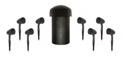
BOX CONTENTS
(1) Manual
(1) In-Ground Subwoofer
(2) Silicone filled wire nuts
INTRODUCTION
Thank you for purchasing a Sonance Landscape Series
Subwoofer. When properly installed, the subwoofer will
provide you with years of outdoor entertainment. To get
the most out of your new subwoofer, please read this
manual thoroughly before you begin installation.
IMPORTANT: Read this section in its entirety before
attempting use of speaker.
IMPORTANT SAFETY INSTRUCTIONS
Always follow these basic safety precautions when using
your speaker to reduce the risk of fire, electric shock,
and injury to prople or objects.
1. Read all the safety and operating instructions before
operating the speaker and retain them for future
reference.
2. Adhere to all warnings and precautions listed on the
speaker and in the operating instructions.
3. Follow all operating instructions.
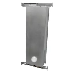
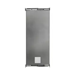
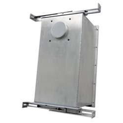
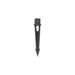
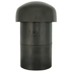
SUBWOOFER PLACEMENT
NOTE: Subwoofers are very heavy, always team lift.
The SLS system is designed to deliver a seamless, evenly
dispersed sound field in an ‘open air’ environment. An
array of multiple Satellite speakers and Subwoofers
should be strategically placed to minimize ‘hot spots’ and
‘nulls’ as you move around the outdoor entertainment area.
NOTE: As a general guideline, one subwoofer will cover
about 2,000 square feet of listening area.
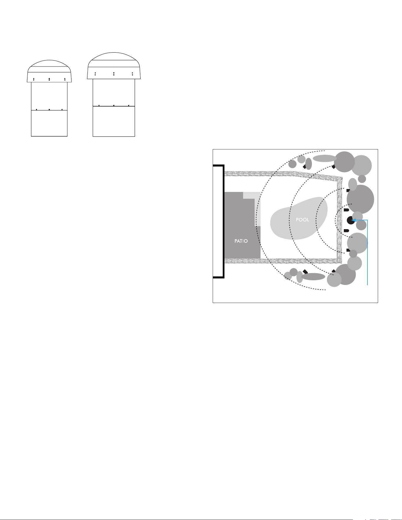
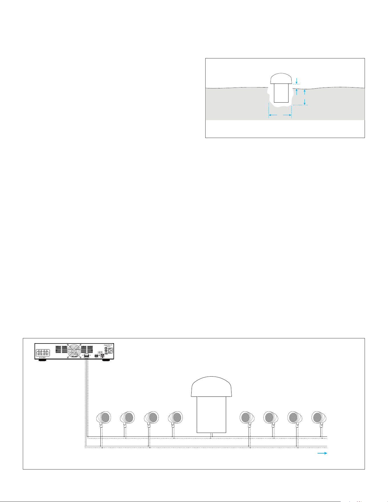
1. Select a central location for the subwoofer if using
only one (see Figure 1). If using multiple subs, select
locations that are the same distance from the main
listening area. Sonance recommends one SLS sub
installed after every four to five satellites in a chain.
Figure 1: Subwoofer Placement
ADJUSTABLE TAP
SLS features a wide bandwidth Sonance Laminated Core
Transformer (SLCT) with an adjustable tap, allowing the
system to be configured for 70V/100V or 8 ohm. If using
this SLS product in an 8 ohm application, ensure the
tap switch is positioned to the 8 ohm setting. If using
this product in a 70V/100V system, ensure the tap is
positioned to one of the 70V/100V settings.
NOTE: Ensure that all satellites and subwoofers are set
to either 70V/100V or 8 ohm tap settings to avoid any
damage to your amplifier. DO NOT combine products
set to any of the 70V/100V settings with products set
to the 8 ohm setting on a single amplifier.
Some 70V/100V system designs will require variations
of higher and lower output in dierent areas of the
landscaping. The SLCT adjustable tap allows each
satellite or subwoofer to be individually dialed to the
desired output. Adjusting the tap settings will impact
your wattage calculations. Please review the Wattage
Calculator on the Sonance website: sonance.com/
collections/sonance-landscape-series
Sub
LS12T SUB LS15T SUB
3
NOTE: This product ships with the SLCT adjustable
tap set to 300W. Adjustments can be made to the
tap switch once all the satellites and subwoofers are
connected to achieve the appropriate output level.
SONAMP DSP 2-750 AMP POWER
PLANNING
The maximum number of satellites and subwoofers that
can be used in a system will depend on the amplifier
power. It is important to calculate the amplifier power
your installation will require before you begin. Multiple
amplifiers may be required in large installations.Refer to
the SLS wattage calculator on the Sonance website:
sonance.com/collections/sonance-landscape-series
SUBWOOFER INSTALLATION
Sonance Landscape Series systems allow for speakers
to be daisy chained in series from one speaker to the
next. In a typical system with one zone of audio, run a
stereo or 4-conductor speaker wire from the amplifier
to the closest speaker. Designate the first speaker as
either left or right and connect the appropriate positive
and negative wires to the speaker terminals. Continue
alternating the wires between the left and right channels
for each speaker, creating a daisy chain of stereo
satellites. The subwoofer can be wired anywhere in the
chain and will receive either left or right speaker wires
(see Figure 3).
NOTE: Sonance strongly recommends the use of 14/4
direct burial wire for distances up to 200 feet and 12/4
direct burial for longer runs. Keep wires as short as
possible to minimize resistive wire losses.
CAUTION: The amplifier should not be connected to
AC power until all SPEAKER WIRE connections are
completed. High power 70 volt amplifiers present
a serious shock hazard.
1. Locate the subwoofer in an area that will not flood
with standing water.
Figure 3: 70V SLS Wiring Diagram Configuration: 4 SATs | 1 SUB or 8 SATs | 1 SUB
Note: The subwoofer
can be connected at any
point in the daisy chain.
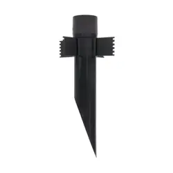
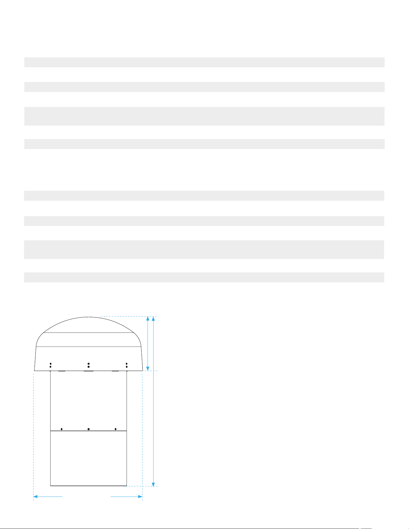
2. Dig the hole using the following guide (see Figure 2).
• LS12T SUB: A=4” B=16” C=17”
• LS15T SUB: A=4” B=19” C=20”
3. Prepare a ‘bed’ for the subwoofer that is reasonably
free of voids and large rocks.
NOTE: the subwoofer is very heavy, always team lift. Do
not hold by speaker wire or plastic strain relief.
4. Make the appropriate tap selection on the subwoofer
before lowering into the ground. Remove the tap cap
and rotate the tap dial to the correct 70V/100V or 8
ohm selection and then firmly reinstall the cap.
5. Place the subwoofer into the ground.
6. Fine tune the enclosure depth as required so that the
bottom of the canopy will be 4” above the finished
grade after backfill.
7. Dig a 4–5” deep trench to run the speaker wires in.
8. Run the wire through the trench from your amplifier to
the first speaker location.
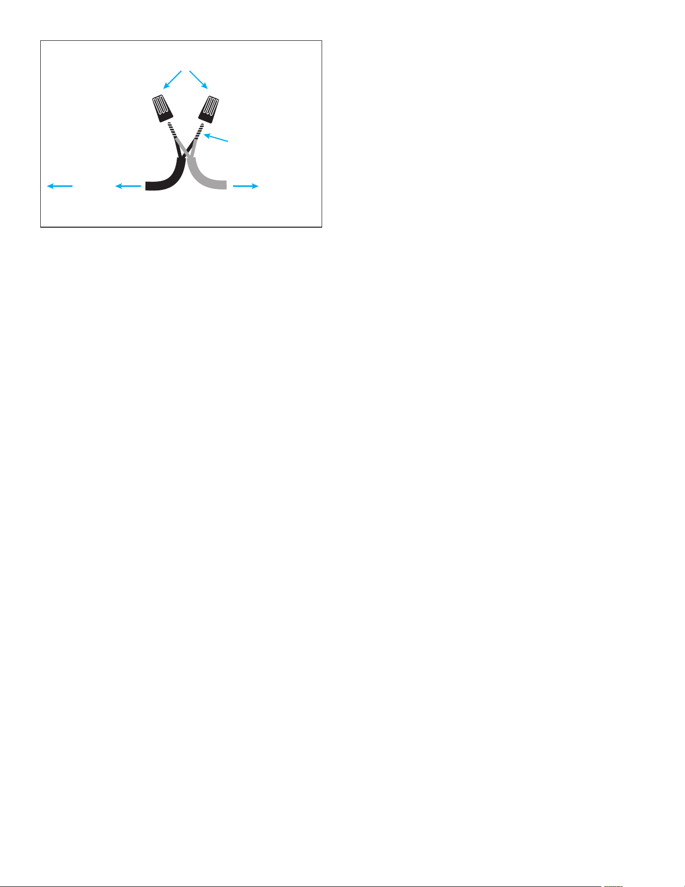
9. Connect the direct burial wire to each speaker wire,
connections should be made with either silicone filled
wire connectors or appropriate junction boxes (see
Figure 4).
A
C
B
A
C
B
Figure 2
Sonamp DSP 2-750 Amplifier
LS4T SATs/LS6T SATs and LS12T SUB or LS15T SUB
Expandable
LeftLeft RightRight
S/N
CAUTION
RISK OF ELECTRIC SHOCK
DO NOT OPEN
AVIS
RISQUE DE CHOC ELECTRIQUE
NE PAS OUVRIR
AC 100-120V ~ 60Hz
AC 220-240V ~ 50Hz
IR
CONTROL
TCP/IP
D
EFAULT IP
1
92.168.1.50
IR
STATUS
IN
OUT
CAUTION
REPLACE FUSE ONLY WITH SAME
T
YPE AND RATING OF FUSE
A
TTENTION
REMPLACER UNIQUEMENT AVEC
LE MEME TYPE ET CALIBRE DU
FUSIBLE
T10AL / 250VAC
DSP2-750 MKII
+
1-LEFT
1-RIGHT
-
BRIDGE
4OHMSMIN
VOLTAGE TRIGGER
IN OUT
+
--
+
3-30 volts AC /DC
IN
OUT
IN
OUT
1-L 1-R 2-L 2-R
+
-
+
-
LeftLeft RightRight
4
Figure 4: Connect
Twist wires
together
Waterproof
Wire Nuts
To next
speaker/sub
To Amp
Positive
+
Negative
-
IMPORTANT: Be sure not to let any stray ‘+’ and ‘–’
strands touch each other. Touching strands can cause
a short-circuit that could damage your amplifier and
degrade sound quality.
10. After all the speaker connections are completed,
connect the wires to your amplifier.
11. Turn your amplifier on and test the system with
your favorite music. If the speakers are operating
properly, refill the wire trench and enjoy your new
speakers.
5
LS12T SUB
Woofer 12” (305mm) polypropylene cone with a Santoprene rubber surround
Frequency Response 22Hz - 100kHz +/-3dB
Transformer Taps 70V 300W, 150W, 75W | 100V 300W, 150W
Impedance 8 ohms
Enclosure Material Low density polyethylene (LDPE) non-corrosive sealed enclosure.
Rust resistant, powder coated aluminum canopy
Overall Dimensions (WxH) 16.97” x 29.13” (431mm x 740mm)
Woofer Enclosure (HxDia) 20.75” x 13.78” (527mm x 350mm)
Shipping Weight 70.55 lbs (32kg)
TECHNICAL SPECIFICATIONS
LS15T SUB
Woofer 15” (381mm) polypropylene cone with a Santoprene rubber surround
Frequency Response 20Hz - 100kHz +/-3dB
Transformer Taps 70V 300W, 150W, 75W | 100V 300W, 150W
Impedance 8 ohms
Enclosure Material Low density polyethylene (LDPE) non-corrosive sealed enclosure.
Rust resistant, powder coated aluminum canopy
Overall Dimensions (WxH) 21.26” x 33.58” (540mm x 853mm)
Woofer Enclosure (HxDia) 23.01” x 16.73” (584mm x 425mm)
Shipping Weight 83.77 lbs (38kg)
Overall Width
Woofer
Enclosure
Height
Overall
Height

6
©2025 Sonance. All rights reserved. Sonance is a registered trademarks of Dana Innovations. Due to continuous product improvement, all features and
specifications are subject to change without notice. For the latest Sonance product specification information visit our website: www.sonance.com
SONANCE • 991 Calle Amanecer • San Clemente, CA 92673 USA • PHONE: (949) 492-7777
11.24.2025
LIMITED LIFETIME WARRANTY
Sonance warrants to the first end-user purchaser that this Sonance-brand product (“Product”), when purchased from an authorized
Sonance Dealer/Distributor, will be free from defective workmanship and materials for the life of the Product, except for the grille, which
is warranted for five (5) years. Sonance will at its option and expense either repair the defect or replace the Product with a new or
remanufactured Product or a reasonable equivalent.
EXCLUSIONS: TO THE EXTENT PERMITTED BY LAW, THE WARRANTY SET FORTH ABOVE IS IN LIEU OF, AND EXCLUSIVE OF, ALL
OTHER WARRANTIES, EXPRESS OR IMPLIED, AND IS THE SOLE AND EXCLUSIVE WARRANTY PROVIDED BY SONANCE. ALL OTHER
EXPRESS AND IMPLIED WARRANTIES, INCLUDING THE IMPLIED WARRANTIES OF MERCHANTABILITY, IMPLIED WARRANTY OF
FITNESS FOR USE, AND IMPLIED WARRANTY OF FITNESS FOR A PARTICULAR PURPOSE ARE SPECIFICALLY EXCLUDED. No one is
authorized to make or modify any warranties on behalf of Sonance.
The warranty stated above is the sole and exclusive remedy and Sonance’s performance shall constitute full and final satisfaction of all
obligations, liabilities and claims with respect to the Product.
IN ANY EVENT, SONANCE SHALL NOT BE LIABLE FOR CONSEQUENTIAL, INCIDENTAL, ECONOMIC, PROPERTY, BODILY INJURY, OR
PERSONAL INJURY DAMAGES ARISING FROM THE PRODUCT, ANY BREACH OF THIS WARRANTY OR OTHERWISE.
This warranty statement gives you specific legal rights, and you may have other rights which vary from state to state. Some states do
not allow the exclusion of implied warranties or limitations of remedies, so the above exclusions and limitations may not apply. If your
state does not allow disclaimer of implied warranties, the duration of such implied warranties is limited to period of Sonance’s express
warranty.
Your Product Model and Description: Sonance Landscape Series LS12T SUB | LS15T SUB In-Ground Subwoofers
Additional Limitations and Exclusions from Warranty Coverage: The warranty described above is non-transferable, applies only to the
initial installation of the Product, does not include installation of any repaired or replaced Product, does not include damage to allied
or associated equipment which may result for any reason from use with this Product, and does not include labor or parts caused by
accident, disaster, negligence, improper installation, misuse (e.g. overdriving the amplifier or speaker, excessive heat or cold or humidity,
outdoor installation), or from service or repair which has not been authorized by Sonance.
Obtaining Authorized Service: To qualify for the warranty, you must contact your authorized Sonance Dealer/Installer or call Sonance
Customer Service at (949) 492-7777, must obtain a return merchandise number (RMA), and must deliver the Product to Sonance
shipping prepaid during the warranty period, together with the original sales receipt, or invoice or other satisfactory proof of purchase.
In order to initiate a warranty claim:
1. Contact Sonance Technical Support with a description of the fault, the speaker’s serial number and the date of purchase from an
authorized Sonance dealer at: [email protected]
2. Sonance Technical Support will follow-up and may request additional troubleshooting.
3. Once a determination has been made on the fault, Sonance Customer Service will follow-up by email. Please have a scanned copy of
your Sonance Landscape Series Speaker sales invoice ready to send upon request to document the speaker’s warranty status.
4. Sonance Customer Service will provide an RMA number to be included on the shipping label of the packaging. Please send the
speaker back in its original factory carton, which has been specifically designed to protect the speaker during transit.
Contact us at: https://www.sonance.com/company/contact