Visit Our Website
SCAN ME
PyleUSA.com
USER GUIDE
Wireless BT Streaming Studio Mixer
Questions or Comments?
We are here to help!
Phone: 1.718.535.1800
PyleUSA.com/ContactUs
www.PyleUSA.com2 www.PyleUSA.com 3
READ ALL INSTRUCTIONS CAREFULLY BEFORE USING THIS PRODUCT.
RETAIN THIS OWNER’S MANUAL FOR FUTURE REFERENCE.
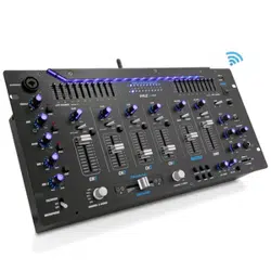
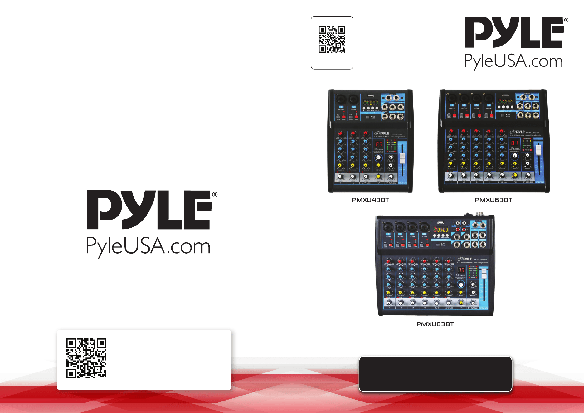
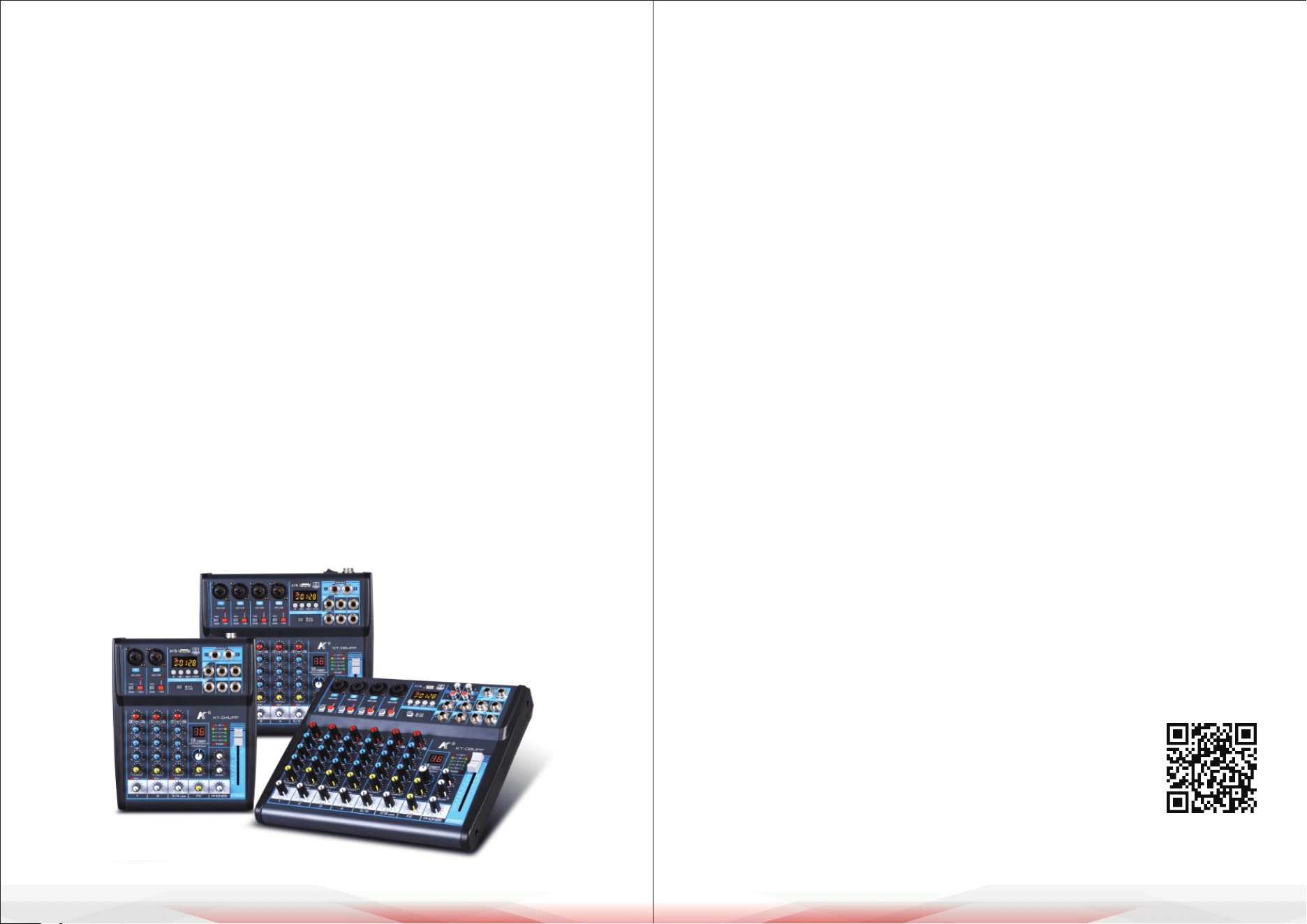
PMXU43BT - PMXU63BT - PMXU83BT
Wireless BT Streaming Studio Mixer DJ Controller
Audio Mixing Console System
Features:
• DJ & Studio Console Mixer System
• Built-in Wireless BT Receiver
• FX (Analog Eects) & 16 Bit DSP processor
• Direct-to-Computer Connect & Sound Record Ability
• LCD Digital Display & Front Panel Control Center
• Rotary Adjustment Knobs & LED Indicator Lights
• MP3 Digital Audio File Compatibility
• USB Interface: MP3 Flash Drive Reader/Computer Connection
• Connect & Stream Audio from External Devices
• (2) 1/4’’ (L/R) MAIN Outputs
• 1/4’’ Headphone Jack
• Stereo Level Fader/Slider
• Output Signal Level Indication
• BUS Audio Control
• PAD Channel Source Input Switch
• Independent Channel Input Audio Conguration
• Gain, High, Mid, Low, FX/Send, Level, Base + Tone Adjustment
• +48V Phantom Power Control
• Power ON/OFF Switch
• Used for Professional Studio Applications & On-Stage Performances
Wireless BT Connectivity:
• Hassle-Free Audio Streaming Ability
• Works with All of Today’s Latest Devices
(Smartphones, Tablets, Laptops, Computers, etc.)
• Wireless BT Network Name: ‘KT-08UP’
• Wireless BT Version: 4.0
• Wireless Range: 15’+ ft.
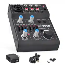
What’s in the Box:
• Wireless BT Studio Mixer
• Power Adapter Cable, 4-Pin
Technical Specs:
• Mic Input: Sensitivity/Impedance: 1.5mV/750 Ohm
• Input Frequency Response: 20Hz-20kHz, +/-3dB
• Input Distortion: 0.03%, 1kHz/150mV Input
• Channel GAIN Adjustment: +20/+64 (-6/+38)
• HIGH Gain: +/-15 dB, 12kHz Frequency Shelving
• MID Gain: +/-15 dB, 2.5kHz Frequency Shelving
• LOW Gain: +/-15 dB, 80kHz Frequency Shelving
• HIGH/MID/LOW Adjustment: -15/+15dB
• Stereo Output Level Meter: 5-Segment (+6, +3, 0, -3, -10dB)
• PAD Input Channel Adjustment: 26dB
• Peak CLIP Level: < 3dB
• Phantom Power Voltage: +48V
• Power Supply: 100-240V (+/-15V DC Power Adapter)
• Digital Audio File Compatibility File-Types: MP3, WAV
California Prop 65 Warning
WARNING:
This product may expose you to chemicals, which is known to
the state of California to cause cancer, birth defects and other
reproductive harm. Do not ingest.
For more info go to: www.P65warnings.ca.gov
• Multi 4-Channel Audio
Source Mixing
• (2) XLR/14’’ Combo Audio
LINE/Microphone Inputs
• 1/4’’ Mono + Stereo Inputs
• 1/4’’ Send + Return Inputs
• Input Mixer Channels:
4-Ch. (+ FX/Headphones)
• Dimensions (L x W x H):
9.3’’ x 7.5’’ x 2.6’’
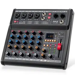
• Multi 6-Channel Audio
Source Mixing
• (4) XLR/14’’ Combo Audio
LINE/Microphone Inputs
• 1/4’’ Mono + Stereo Inputs
• 1/4’’ Send + Return Inputs
• Input Mixer Channels:
6-Ch. (+ FX/Headphones)
• Dimensions (L x W x H):
9.3’’ x 9.7’’ x 2.6’’
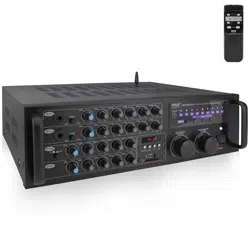
• Multi 8-Channel Audio
Source Mixing
• (4) XLR/14’’ Combo Audio
LINE/Microphone Inputs
• (2) Pair RCA (L/R) Inputs
• (2) Pair 1/4’’ Mono + Stereo Inputs
• 1/4’’ Send + Return Inputs
• Input Mixer Channels:
8-Ch. (+ FX/Headphones)
• Dimensions (L x W x H):
9.3’’ x 10.8’’ x 2.6’’
PMXU63BTPMXU43BT PMXU83BT
www.PyleUSA.com4 www.PyleUSA.com 5
GENERAL SPECIFICATIONS
IMPORTANT SAFETY INSTRUCTIONS
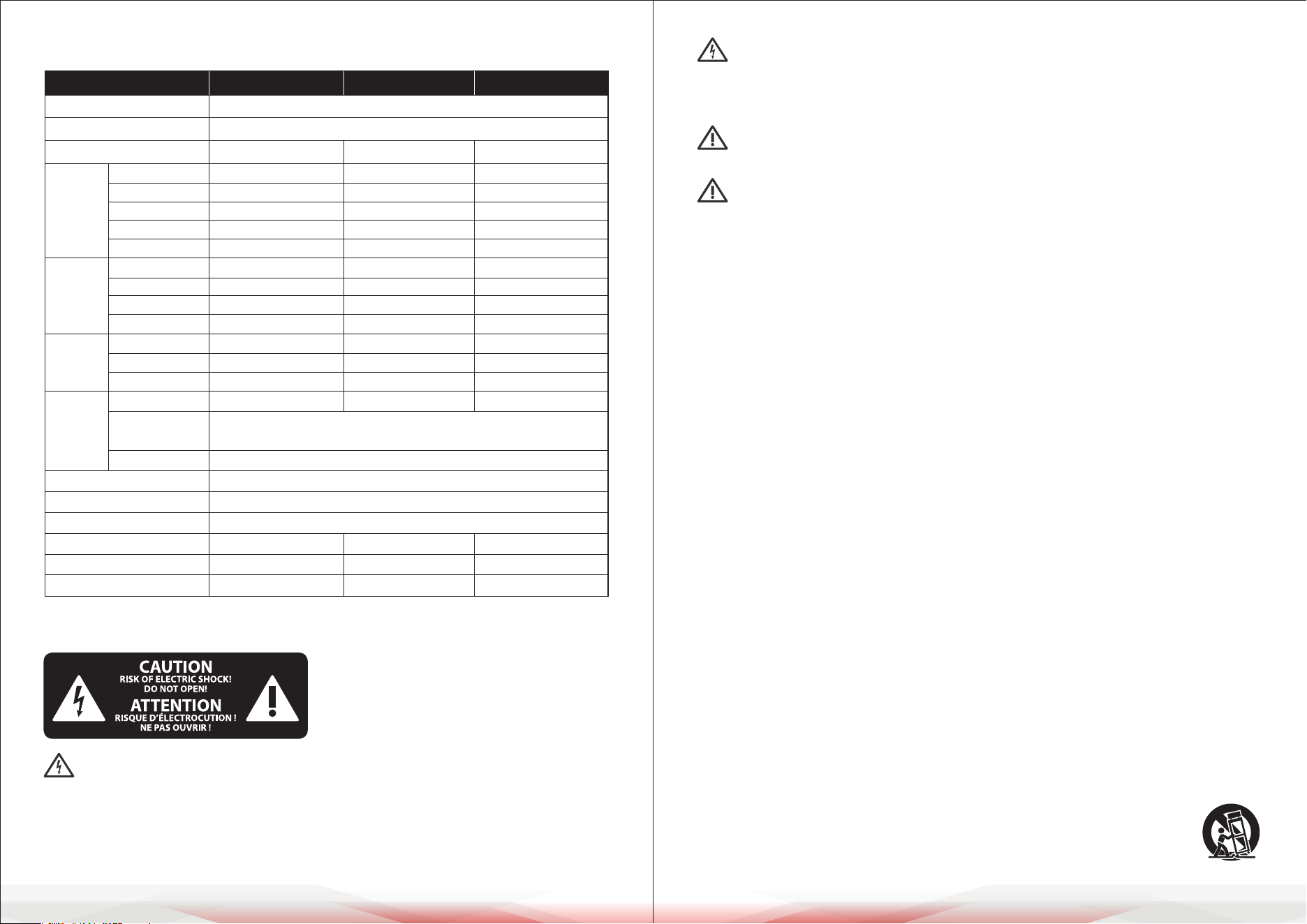
This symbol indicates the presence of uninsulated dangerous voltage
inside the enclosure, which may be sucient to constitute a risk of electric
shock.
This symbol alerts you to important operating and maintenance instructions
in the accompanying literature. Please read the manual thoroughly.
Important Warnings:
• To reduce the risk of electric shock, do not remove the top cover (or rear section).
No user-serviceable parts are inside. Refer servicing to qualied personnel.
• To reduce the risk of re or electric shock, do not expose this appliance to rain
or moisture. Do not allow dripping or splashing liquids, and avoid placing
objects lled with liquids (e.g., vases) on the apparatus.
• These service instructions are for qualied personnel only. Repairs must be
carried out by authorized service personnel to avoid the risk of electric shock.
General Guidelines
1. Read all instructions carefully before use.
2. Keep these instructions for future reference.
3. Follow all warnings and guidance provided.
4. Comply with all operating instructions.
5. Do not use this equipment near water.
6. Clean only with a dry cloth.
7. Ensure ventilation openings are not blocked.
Install according to the manufacturer’s guidelines.
8. Do not place the apparatus near heat sources such as radiators, heat registers,
stoves, or other equipment that produces heat (e.g., ampliers).
9. Do not override the safety features of a polarized or grounding-type plug.
A polarized plug has two blades, one wider than the other. A grounding-type
plug has two blades and a grounding prong. If the plug does not t into your
outlet, contact a qualied electrician to replace the obsolete outlet.
10. Protect the power cord from being walked on, pinched, or damaged,
especially at the plug, receptacles, or where it exits the apparatus.
11. Use only attachments or accessories specied by the manufacturer.
12. Use the apparatus only with the cart, stand, tripod, bracket, or table
specied by the manufacturer or sold with the equipment.
When using a cart, move it carefully to avoid tip-over injuries.
MODEL PMXU43BT PMXU63BT PMXU83BT
Frequency Response
Total Harmonic Distortion
Channel
Input
Channels
MIC/LINE
STEREO
MP3
USB Sound card
Wireless BT
REC/RCA
CTRL/6.35 Jack
Main/6.35 Jack
Phones/6.35 Jack
Output
Channels
INSERT
Send (OUT)
Return (IN)
Auxiliary
Input
Channel
Function
PAD
EQ/3-Band
Peak LED
Level Meter
Main control equalizer
Eects/FX
Phantom power voltage
Power input
Power consumption
20Hz-20KHz 1dB+4dBµ @1KHz
<0.5%@+4dBµ (22Hz - 22KHz)
4-CH 6-CH 8-CH
2 (XLR+6.35 Jack) 4 (XLR+6.35 Jack) 4 (XLR+6.35 Jack)
1 (3-4) 1 (5-6) 2 (5-6/7-8)
1 1 1
2.0 Type-A 2.0 Type-A 2.0 Type-A
1 1 1
/ / /
1 1 1
/ / /
1 1 1
L/R L/R L/R
1 1 1
1 1 1
26dB 26dB 26dB
HIGH: Gain/±15dB, Frequency: 12KHz shelving
MID: Gain/±15dB, Frequency: 2.5KHz shelving
LOW: Gain/±15dB, Frequency: 80Hz shelving
LED turns ON when post EQ signal reaches 3dB below clipping level
2 x 5 segment LED meter (+6, +3, 0, -3, -10dB)
/
16 DSP
+48V +48V +48V
±15VDC +48VDC ±15VDC +48VDC ±15VDC +48VDC
11W 14W 17W
Caution: Terminals marked with this symbol carry electrical current of
sucient magnitude to pose a risk of electric shock. Use only high-quality
professional speaker cables with ¼" TS or twist-locking plugs pre-installed.
Any other installation or modication should only be performed by
qualied personnel.

www.PyleUSA.com6 www.PyleUSA.com 7
13. Unplug the apparatus during lightning storms or when unused for extended
periods.
14. Refer all servicing to qualied personnel. Servicing is required when the
apparatus is damaged in any way, including a damaged power cord or plug,
liquid spillage, objects falling into the unit, exposure to rain or moisture,
abnormal operation, or physical damage.
15. Connect the apparatus to a properly grounded MAINS socket outlet.
16. Ensure the disconnect device (such as a MAINS plug or appliance coupler)
remains easily accessible and operable at all times.
INTRODUCTION
Caution:
We want to emphasize that prolonged exposure to high volume levels can
damage your hearing, as well as your headphones or loudspeakers. Always turn
the MAIN MIX and PHONES controls fully counterclockwise before powering on
the unit. Adjust volume levels carefully to avoid damage.
Important Notes About Installation
The sound quality of the device may be aected by powerful broadcasting
stations or other high-frequency sources. To minimize interference, increase the
distance between the transmitter and the device, and use shielded cables for
all connections.
General Functions of a Mixing Console
A mixing console performs three key functions:
1. Signal Processing:
• Preamplication
• Level adjustment
• Eects mixing
• Frequency equalization
2. Signal Distribution:
• Summing signals to aux sends for eects processing and monitor mixes
• Routing to one or more power ampliers, control room outputs, and 2-track
outputs.
3. Mixing:
• Adjusting volume levels
• Equalizing frequencies
• Positioning individual signals within the stereo eld
• Controlling the overall mix level to suit recording devices, crossovers, or
power ampliers
Before You Begin
Shipment
Your mixing console has been carefully packaged to ensure safe transport.
However, please inspect the packaging and contents for any signs of physical
damage that may have occurred during transit.
If you nd any damage, do not return the unit to us. Instead, contact your dealer
and the shipping company immediately. Claims for damage or replacement
may not be honored if these steps are not followed.
Initial Setup
To ensure proper operation and prevent overheating, make sure there is
adequate space around the unit for cooling. Do not place the mixing console
near high-temperature devices like radiators or power ampliers.
• Connect the console to the mains using the supplied power cable.
The unit meets all required safety standards. If a fuse blows, replace it only
with one of the same type and rating.
• Important: Never connect the mixer to the power supply while the power
supply is connected to the mains. Always connect the power supply to the
console rst, and then connect it to the mains.
• Ensure all units are properly grounded. For your safety, never remove or
disable ground connectors on electrical devices or power cables.
• Installation and operation should only be carried out by qualied personnel.
The user must maintain sucient electrical contact with the ground to prevent
electrostatic discharge from aecting the unit’s performance.
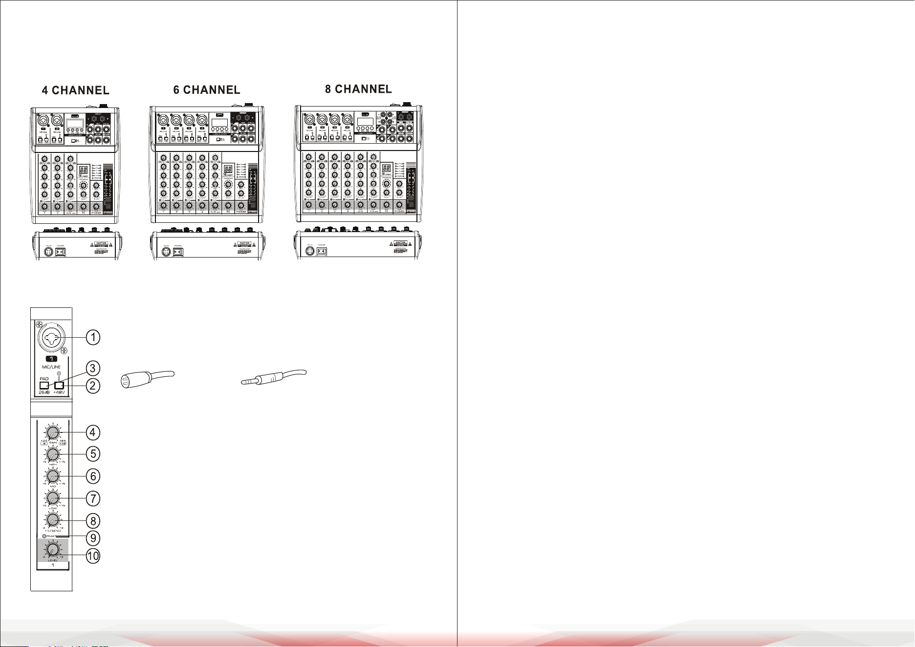
4. [GAIN] Control
• Adjusts the basic volume of each channel for optimal performance.
• If the [PEAK] LED lights up, reduce the gain by turning this control counter-
clockwise.
5. [HIGH] Treble Control
Adjusts the high-frequency (treble) tones, allowing enhancement or
attenuation of up to ±15 dB at 12 kHz.
6. [MID] Midrange Control
Adjusts the midrange tones, allowing enhancement or attenuation of up to
±15 dB at 2.5 kHz.
7. [LOW] Bass Control
Adjusts the low-frequency (bass) tones, allowing enhancement or attenuation
of up to ±15 dB at 80 Hz.
8. [FX] Control
• Adjusts the signal level sent from the channel to the FX/reverb line.
• For stereo channels, signals from the left (L) and right (R) inputs are mixed
before being sent to the FX line.
9. [PEAK] LED Indicator
• Flashes when the input signal or equalized volume is too high.
• To resolve this, reduce the gain by turning the [GAIN] Control counterclockwise.
10. [LEVEL] Control
Balances the volume of each channel within the overall mix.
MIC INPUT
Each mono input channel includes a balanced microphone input via the XLR
connector, with a switchable +48V phantom power supply for condenser
microphones.
• The preamps deliver clean, distortion-free gain, comparable to high-quality
external preamps.
www.PyleUSA.com8 www.PyleUSA.com 9
CONTROL ELEMENTS AND CONNECTORS
This chapter provides a detailed overview of the control elements of your
mixing console. All controls, switches, and connectors are explained below.
CHANNEL INPUT
1. [MIC/LINE] Mono Input: Connect a microphone, musical
instrument, or audio device (e.g., CD player) to this input.
Supports both XLR and unbalanced 1/4" plugs.
2. [+48V PHANTOM] Button/LED
• Activates the DC +48V phantom power for XLR plugs on the
MIC/LINE mono input.
• Turn on this button when using a condenser microphone
requiring phantom power.
• When activated, the LED indicator will light up.
3. [PAD] Button
• Attenuates the input signal when turned ON.
• Use this switch if you hear distortion or if the [PEAK] LED
indicator lights up.
XLR UNBALANCED 1/4 " PLUG
www.PyleUSA.com10 www.PyleUSA.com 11
• Important: Mute your playback system before activating the phantom power
to avoid loud thumping noises in your loudspeakers.
LINE INPUT
Each mono input channel also features a balanced line input on a 1/4" connector.
Unbalanced devices (mono jacks) can also be connected to these inputs.
Note:
You can use either the microphone input or the line input on a single channel,
but not both simultaneously.
GAIN CONTROL
The [GAIN] Control adjusts the input gain for the connected signal source.
Always turn the control fully counterclockwise before connecting or
disconnecting any device to avoid sudden volume spikes or damage.
FX (Eects) Control
The FX send (or AUX send) allows you to send signals from one or more
channels to an eects device.
1. The signals are summed to an FX bus, which appears at the console’s FX Send
Output.
2. From there, the signal can be sent to an external eects unit, and the
processed signal can be returned to the console through the aux return
connectors or regular channel inputs.
Features of FX Control:
• Each FX send is mono and provides up to +15 dB of gain.
• Congured post-fader, ensuring the mix of the dry signal and eects remains
consistent with the channel’s FX send settings, even when the level knob is
lowered.
• This setup ensures eects are muted when the channel's level is turned down
completely.
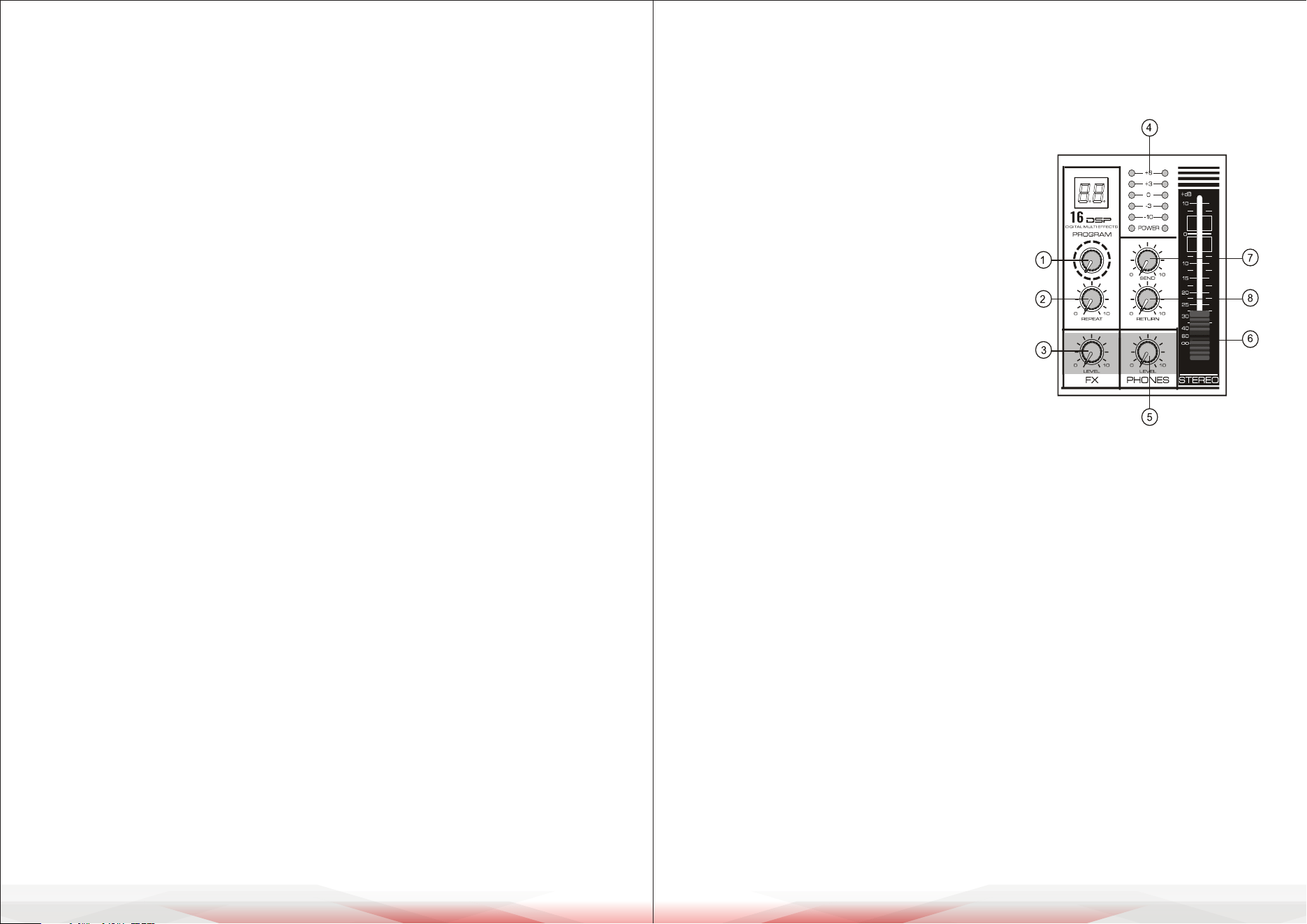
MAIN CONTROL
This section describes the primary controls, connectors, and functions of the
mixer.
4. Level Indicators:
Show the signal levels from the [STEREO OUT] outputs.
• If the [PEAK] indicator lights up in red, reduce the output level by adjusting
the [LEVEL] Controller.
5. [LEVEL PHONES] Earphone Volume Controller: Adjusts the volume for the
connected headphones.
6. [STEREO LEVEL] Fader:
Controls the overall volume of the [STEREO OUT] output signal.
7. [SEND] Level Controller:
Adjusts the signal level sent to the [SEND OUT] socket.
8. [RETURN] Level Controller: Adjusts the volume of the return signal from an
external device connected to the [RETURN] Input Socket.
1. [PROGRAM] Controller: Select from 16
internal digital eects. The selected eect
signal is applied equally to both the left (L)
and right (R) stereo outputs.
2. [REPEAT] Echo Controller: Adjust to set
the desired level of internal echo for the
eects signal.
3. [FX LEVEL] Eects Return Level Controller:
Controls the volume of the eects return
signal.
www.PyleUSA.com12 www.PyleUSA.com 13
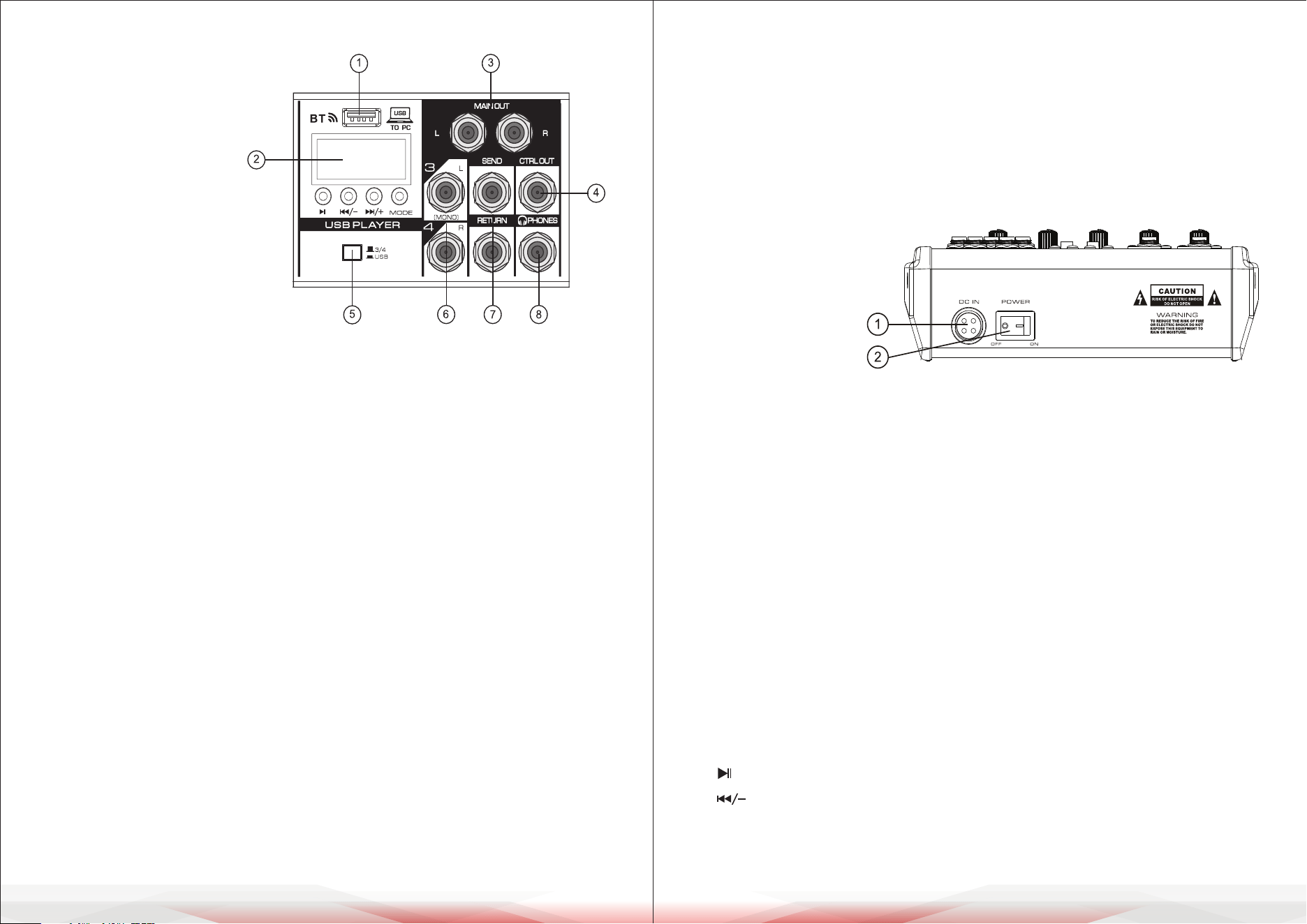
CONNECTIONS AND INTERFACES
1. USB Interface
• Supports MP3 input or
computer connection.
• Can be used for USB
ash drive (U-disk)
playback or software-based
recording.
2. MP3 Display
Displays playback status and
details for the connected MP3
device.
3. [MAIN OUT] Output: Connect to an active speaker or external amplier for
main audio output.
4. [CTRL OUT] Output: Connect to monitor speakers for control room monitoring.
5. Converting Switch for Channel 3/4 and USB Signal:
Switches between Channel 3/4 inputs and USB signal routing.
6. Channel Input Socket (Stereo):
• 8-channel mixers: Two groups of input sockets.
• 4-channel and 6-channel mixers: One group of input sockets.
• If only the L (MONO) socket is used, the mixer will send the same mono
signal to both L and R outputs.
7. [SEND & RETURN] Sockets
• [SEND Output Socket]: Use to send signals to an external amplier for
monitoring purposes.
• [RETURN Input Socket]: Use to connect an external audio source.
• Combined Usage: Connect to an external audio processor for both send
and return functionality.
8. [PHONES] Socket
• Connect headphones for monitoring.
• Supports stereo headphone plugs.
External Power Input Socket
Receives the external
power supply:
• DC +15V
• DC -15V
• DC +48V
(for phantom power)
• Ground wire connection for safety.
Power Switch: Used to turn the mixer on or o. Ensure all volume controls are
set to their minimum levels before powering on or o to prevent damage to
connected equipment.
WIRELESS BLUETOOTH (BT) CONNECTION
Pairing and Connection
a. Press the "MODE" button to select BT mode. The Wireless BT icon on the
display will ash, and "BT" will be shown on the screen.
b. Enable Bluetooth on your device and select "KT-08UP" from the available
devices. A sound prompt will indicate successful pairing.
BUTTON FUNCTIONS
a. Button: Short press to pause or resume playback.
b. Button:
• Short press: Skip to the previous track.
• Press and hold: Decrease input volume.
www.PyleUSA.com14 www.PyleUSA.com 15
c. Button:
• Short press: Skip to the next track.
• Press and hold: Increase input volume.
d. MODE Button:
Switch between functions in sequence: USB, REC, BT.
RECORDING OPERATION
a. Press the "MODE" button to enter the REC mode.
b. Press the Play/Pause button to start recording. The LED screen will display
the recording time. Press the Play/Pause button again to pause recording.
c. Press the "MODE" button to exit the recording mode.
COMPUTER SOUND CARD FUNCTION
• Connect the included data cable to a PC.
The console will automatically enter the PC playback state.
• On rst connection, your computer will automatically install the necessary
driver. Wait for the installation to complete before playback or recording.
INSTALLATION
Mains Connection
Connect the power supply to the 3-pin mains connector on the rear of the
console using the provided AC adapter. Ensure the adapter meets all applicable
safety standards.
• Important: Use only the supplied power adapter.
• Safety Tip: Do not connect the power supply to the mains while it is attached
to the console. First, connect the console to the power supply, then connect
the power supply to the mains.
Both the power supply unit and the mixing console may heat up during
operation. This is normal.
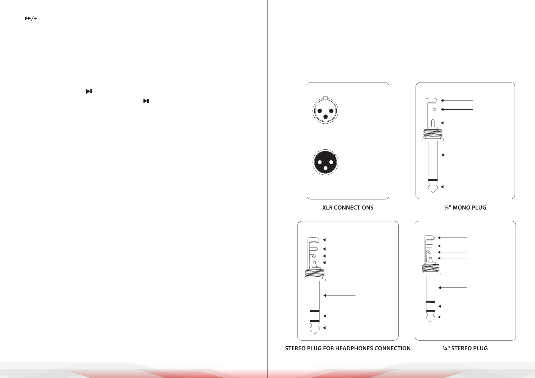
Audio Connections
• Various cables are required for dierent applications. Refer to the illustrations
for proper wiring of the connectors. Use only high-grade cables.
• RCA Cables: Use commercial RCA cables for 2-track inputs and outputs.
• Unbalanced Connections: You may connect unbalanced devices to balanced
inputs/outputs using mono plugs or stereo plugs with the ring and sleeve
bridged (for XLR connectors, connect pins 1 and 3).
Caution: Never use unbalanced XLR connectors (pins 1 and 3 connected) with
MIC input connectors when the phantom power supply is active.
output
For unbalanced use, pin 1 and pin 3
have to be bridged
1 = ground/shield
2 = hot (+ve)
3 = cold (-ve)
input
12
3
1
2
3
Balanced use with XLR connectors
strain relief clamp
sleeve
tip
sleeve
(ground/shield)
Unbalanced ¼" TS connector
tip
(signal)
strain relief clamp
sleeve
ring
tip
sleeve
ground/shield
For connection of balanced and unbalanced plugs,
ring and sleeve have to be bridged at the stereo plug.
Balanced ¼" TRS connector
ring
cold (-ve)
tip
hot (+ve)
strain relief clamp
sleeve
ring
tip
sleeve
ground/shield
¼" TRS headphones connector
ring
right signal
tip
left signal
www.PyleUSA.com16 www.PyleUSA.com 17
CLEANING, MAINTENANCE, AND STORAGE GUIDE
To ensure optimal performance and longevity of your mixing console,
follow these guidelines for cleaning, maintenance, and storage:
Cleaning
• Wipe the console with a soft, dry cloth.
• Do not use liquids or sprays to avoid damaging the device.
• Use a soft brush to clean dust from vents.
Maintenance
• Check cables and power cords regularly for wear or damage.
Replace if needed.
• Ensure knobs, buttons, and faders move smoothly.
• Turn o phantom power when not in use.
• Keep the console in a well-ventilated area away from heat sources.
Storage
• Turn o the console and unplug all cables before storing.
• Store in a cool, dry place away from sunlight, moisture, and dust.
• Use a protective cover or case to prevent damage.
• Organize and store cables separately to avoid tangles.
FCC INFORMATION
WARNING:
Changes or modications not expressly approved by the party responsible
for compliance could void the user’s authority to operate the equipment.
NOTE:
This equipment has been tested and found to comply with the limits for a Class
B digital device, pursuant to Part 15 of the FCC Rules. These limits are designed to
provide reasonable protection against harmful interference in a residential
installation. This unit generates, uses, and can radiate radio frequency energy,
and if not installed and used in accordance with the instructions, may cause
harmful interference to radio communications. However, there is no guarantee
that interference will not occur in a particular installation. If this equipment
does cause harmful interference to radio or television reception, which can be
determined by turning the equipment o and on, the user is encouraged to try
and correct the interference by one or more of the following measures:
• Reorient or relocate the receiving antenna.
• Increase the separation between the equipment and receiver.
• Connect the equipment to an outlet on a circuit dierent from that to which
the receiver is connected.
• Consult the dealer or an experienced radio/TV technician for help.
This device complies with Part 15 of the FCC Rules. Operation is subject to
the following two conditions:
1. This device may not cause harmful interference.
2. This device must accept any interference received, including interference that
may cause undesired operation.
Register Product
Thank you for choosing PyleUSA. By registering your product,
you ensure that you receive the full benets of our exclusive
warranty and personalized customer support. Complete the
form to access expert support and to keep your PyleUSA
purchase in perfect condition.
Start Here
Model Number:
PMXU43BT
PyleUSA.com/pages/register
PMXU63BT
PMXU43BT PMXU83BT