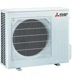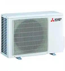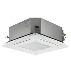
Air Conditioners
Indoor unit
SLZ-M25, M35, M50, M60FA-A
OPERATION MANUAL
For safe and correct use, please read this operation manual thoroughly before operating the air-conditioner unit.
English
FOR USER
VG79Y135H01_Cover.indd 1VG79Y135H01_Cover.indd 1 9/9/2562 BE 2:46 PM9/9/2562 BE 2:46 PM
2
Contents
1. Safety Precautions
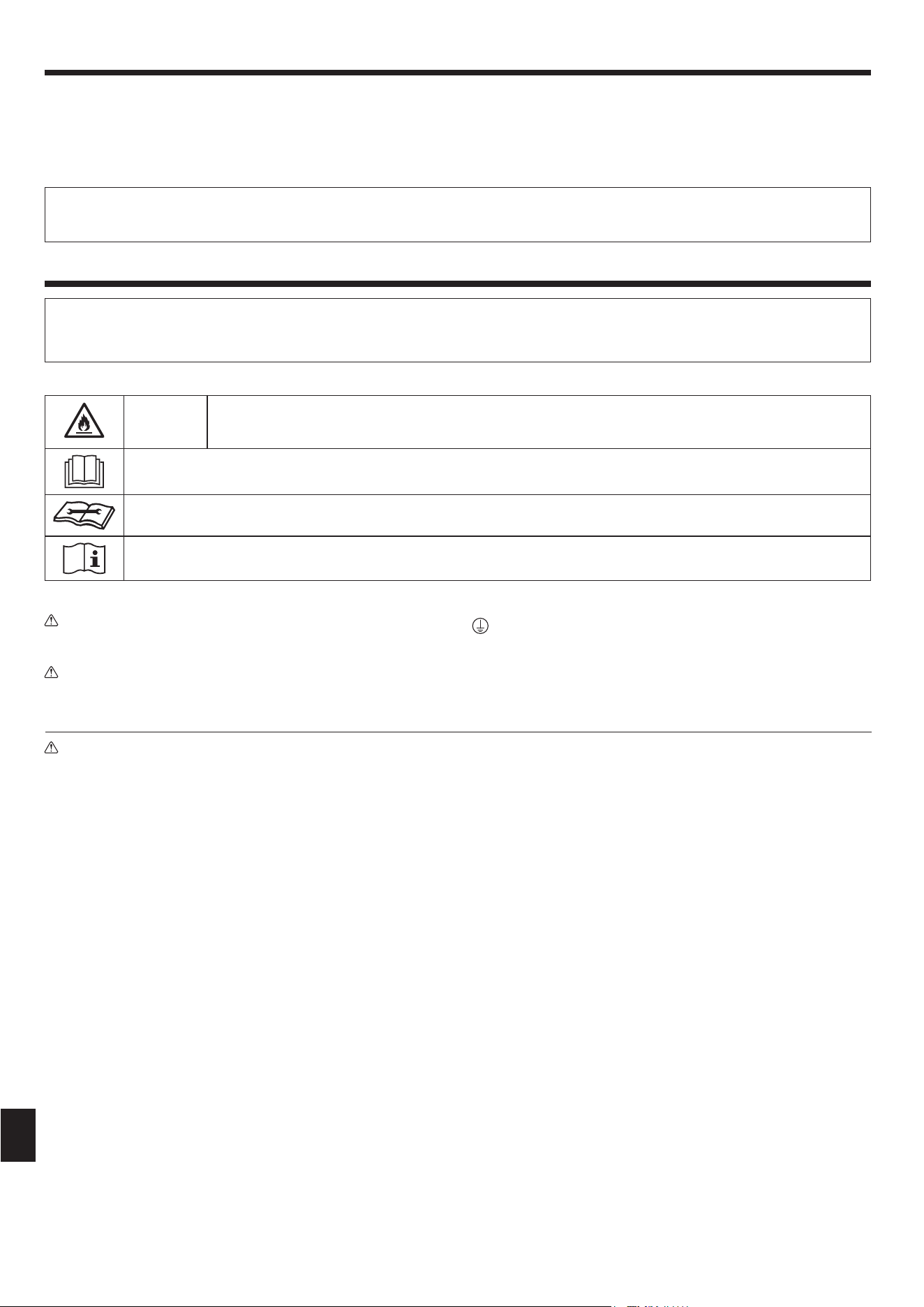
MEANINGS OF SYMBOLS DISPLAYED ON THE UNIT
WARNING
(Risk of fi re)
This mark is for R32 refrigerant only. Refrigerant type is written on nameplate of outdoor unit.
In case that refrigerant type is R32, this unit uses a fl ammable refrigerant.
If refrigerant leaks and comes in contact with fi re or heating part, it will create harmful gas and there is risk of fi re.
Read the OPERATION MANUAL carefully before operation.
Service personnel are required to carefully read the OPERATION MANUAL and INSTALLATION MANUAL before operation.
Further information is available in the OPERATION MANUAL, INSTALLATION MANUAL, and the like.
Symbols used in the text
Warning:
Describes precautions that should be observed to prevent danger of
injury or death to the user.
Caution:
Describes precautions that should be observed to prevent damage
to the unit.
Symbols used in the illustrations
: Indicates a part which must be grounded.
Note:
The phrase “Wired remote controller” in this operation manual refers only to the PAR-40MAA. If you need any information for the other
remote controller, please refer to the instruction book included in this box.
► Before installing the unit, make sure you read all the “Safety Precautions”.
► The “Safety Precautions” provide very important points regarding safety. Make sure you follow them.
► Please report to or take consent by the supply authority before connection to the system.
Warning:
• There appliances are not accessible to the general public.
• The unit must not be installed by the user. Ask the dealer or an
authorized company to install the unit. If the unit is installed im-
properly, water leakage, electric shock or fi re may result.
• Do not alter the unit. It may cause fi re, electric shock, injury or water
leakage.
• Do not stand on, or place any items on the unit.
• Do not splash water over the unit and do not touch the unit with
wet hands. An electric shock may result.
• Do not spray combustible gas close to the unit. Fire may result.
• Do not place a gas heater or any other open-fl ame appliance where
it will be exposed to the air discharged from the unit. Incomplete
combustion may result.
• Do not remove the front panel or the fan guard from the outdoor
unit when it is running.
• When you notice exceptionally abnormal noise or vibration, stop
operation, turn off the power switch, and contact your dealer.
• Never insert fi ngers, sticks etc. into the intakes or outlets.
• If you detect odd smells, stop using the unit, turn off the power
switch and consult your dealer. Otherwise, a breakdown, electric
shock or fi re may result.
• This air conditioner is NOT intended for use by children or infi rm
persons without supervision.
• Young children must be supervised to ensure that they do not play
with the air conditioner.
• If the refrigeration gas blows out or leaks, stop the operation of the
air conditioner, thoroughly ventilate the room, and contact your
dealer.
• This appliance is intended to be used by expert or trained users in
shops, in light industry and on farms, or for commercial use by lay
persons.
• This appliance can be used by children aged from 8 years and above
and persons with reduced physical, sensory or mental capabilities
or lack of experience and knowledge if they have been given super-
vision or instruction concerning use of the appliance in a safe way
and understand the hazards involved. Children shall not play with
the appliance. Cleaning and user maintenance shall not be made
by children without supervision.
• This appliance is not intended for use by persons (including chil-
dren) with reduced physical, sensory or mental capabilities, or
lack of experience and knowledge, unless they have been given
supervision or instruction concerning use of the appliance by a
person responsible for their safety.
• Children should be supervised to ensure that they do not play with
the appliances.
• When installing or relocating, or servicing the air conditioner, use
only the specifi ed refrigerant written on outdoor unit to charge the
refrigerant lines. Do not mix it with any other refrigerant and do not
allow air to remain in the lines.
If air is mixed with the refrigerant, then it can be the cause of ab-
normal high pressure in the refrigerant line, and may result in an
explosion and other hazards.
The use of any refrigerant other than that specifi ed for the system
will cause mechanical failure or system malfunction or unit break-
down. In the worst case, this could lead to a serious impediment
to securing product safety.
• This unit should be installed in rooms which exceed the fl oor space
specifi ed in outdoor unit installation manual.
Refer to outdoor unit installation manual.
1. Safety Precautions .................................................................2
2. Parts Names ...........................................................................3
3. Operation ...............................................................................6
4. Timer.....................................................................................14
5. Care and Cleaning................................................................15
6. Emergency Operation for Wireless Remote-controller .........16
7. Trouble Shooting ..................................................................16
8. Installation, relocation and inspection...................................17
9. Specifi cations .......................................................................18
VG79Y135H01_EN.indd 2VG79Y135H01_EN.indd 2 10/15/2562 BE 9:14 AM10/15/2562 BE 9:14 AM
3
2. Parts Names
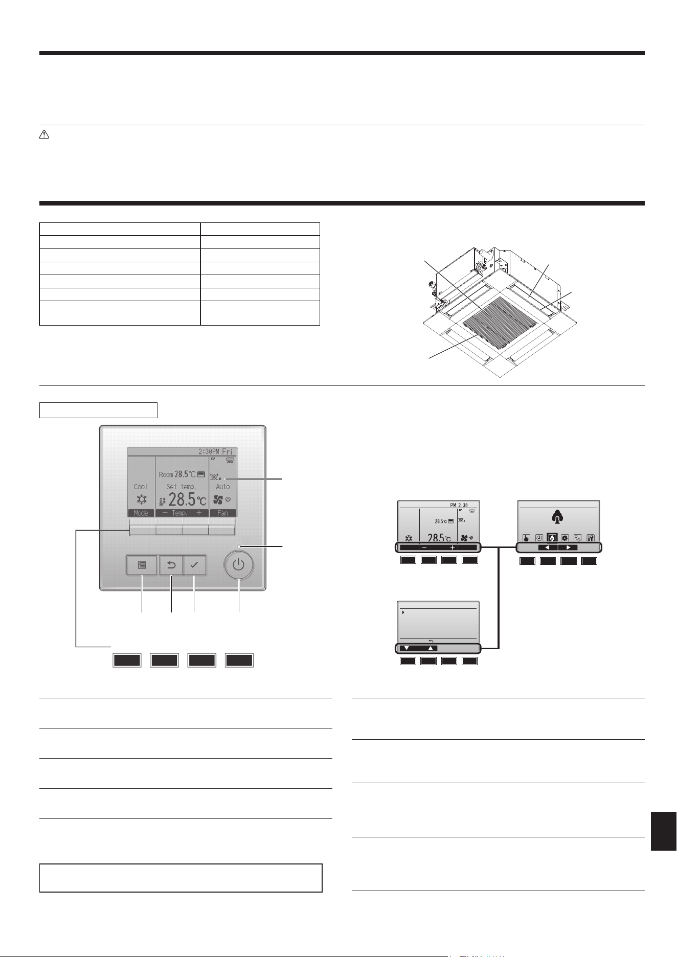
■ Indoor Unit
SLZ-M·FA-A
Fan steps 3 steps
Vane Auto with swing
Louver –
Filter Long-life
Filter cleaning indication 2,500 hr
Wireless remote controller
(PAR-SL97A-E) model No. setting
002
■ SLZ-M·FA-A
4-way Ceiling Cassette
Filter
Air intake
Vane
Air outlet
1. Safety Precautions
■
Wired Remote Controller
The functions of the function buttons change depending on the
screen.
Refer to the button function guide that appears at the bottom of the
LCD for the functions they serve on a given screen.
When the system is centrally controlled, the button function guide
that corresponds to the locked button will not appear.
▌1 [ON/OFF] button
Press to turn ON/OFF the indoor unit.
▌2 [SELECT] button
Press to save the setting.
▌3 [RETURN] button
Press to return to the previous screen.
▌4 [MENU] button
Press to bring up the Main menu.
▌5 Backlit LCD
Operation settings will appear.
When the backlight is off, pressing any button turns the backlight on
and it will stay lit for a certain period of time depending on the screen.
When the backlight is off, pressing any button turns the backlight on
and does not perform its function. (except for the [ON/OFF] button)
▌6 ON/OFF lamp
This lamp lights up in green while the unit is in operation. It blinks while
the remote controller is starting up or when there is an error.
▌7 Function button [F1]
Main display: Press to change the operation mode.
Menu screen: The button function varies with the screen.
▌8 Function button [F2]
Main display: Press to decrease temperature.
Main menu: Press to move the cursor left.
Menu screen: The button function varies with the screen.
▌9 Function button [F3]
Main display: Press to increase temperature.
Main menu: Press to move the cursor right.
Menu screen: The button function varies with the screen.
▌0 Function button [F4]
Main display: Press to change the fan speed.
Menu screen: The button function varies with the screen.
Controller interface
Fri
Room
Set temp.
Mode Temp. Fan
Cool Auto
Main Main menu
Energy saving
Main display:
Cursor
Operation
Vane·Louver·Vent. (Lossnay)
High power
Comfort
Main display Main menu
Function guide
7
7
8
8
9
9
0
0
789
0
• Do not use means to accelerate the defrosting process or to clean,
other than those recommended by the manufacturer.
• The appliance shall be stored in a room without continuously op-
erating ignition sources (for example: open fl ames, an operating
gas appliance or an operating electric heater).
• Do not pierce or burn.
• Be aware that refrigerants may not contain an odour.
Caution:
• Do not use any sharp object to push the buttons, as this may dam-
age the remote controller.
• Never block or cover the indoor or outdoor unit’s intakes or outlets.
Disposing of the unit
When you need to dispose of the unit, consult your dealer.
Function buttons
432 1
5
6
789
0
Menu screen
VG79Y135H01_EN.indd 3VG79Y135H01_EN.indd 3 10/15/2562 BE 9:14 AM10/15/2562 BE 9:14 AM
4
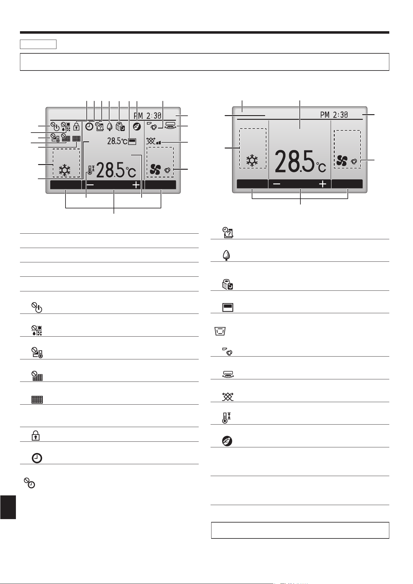
The main display can be displayed in two different modes: “Full” and “Basic”. The factory setting is “Full”. To switch to the “Basic” mode, change the
setting on the Main display setting. (Refer to operation manual included with remote controller.)
▌1 Operation mode
▌2 Preset temperature
▌3 Clock
▌4 Fan speed
▌5 Button function guide
Functions of the corresponding buttons appear here.
▌6
Appears when the ON/OFF operation is centrally controlled.
▌7
Appears when the operation mode is centrally controlled.
▌8
Appears when the preset temperature is centrally controlled.
▌9
Appears when the fi lter reset function is centrally controlled.
▌0
Indicates when fi lter needs maintenance.
▌1 Room temperature
▌2
Appears when the buttons are locked.
▌3
Appears when the On/Off timer, Night setback, or Auto-off timer func-
tion is enabled.
appears when the timer is disabled by the centralized control system.
<Full mode>
* All icons are displayed for explanation.
<Basic mode>
Fri
Mode Temp. Fan
Room
Cool
Set temp. Auto
2
1
5
6
7
8
9
0
1
3
9
4
)
!
2345 6 @78
Fri
Cool
Mode Temp. Fan
Set temp.
Auto
4
3
#
$
2
1
5
▌4
Appears when the Weekly timer is enabled.
▌5
Appears while the units are operated in the energy-save mode. (Will
not appear on some models of indoor units)
▌6
Appears while the outdoor units are operated in the silent mode.
▌7
Appears when the built-in thermistor on the remote controller is acti-
vated to monitor the room temperature (1).
appears when the thermistor on the indoor unit is activated to
monitor the room temperature.
▌8
Indicates the vane setting.
▌9
Indicates the louver setting.
▌)
Indicates the ventilation setting.
▌!
Appears when the preset temperature range is restricted.
▌@
Appears when an energy-saving operation is performed using a
“3D i-See sensor” function.
▌# Centrally controlled
Appears for a certain period of time when a centrally-controlled item is
operated.
▌$ Preliminary error display
An error code appears during the preliminary error.
Most settings (except ON/OFF, mode, fan speed, temperature) can be
made from the Main menu.
Display
2. Parts Names
VG79Y135H01_EN.indd 4VG79Y135H01_EN.indd 4 10/15/2562 BE 9:14 AM10/15/2562 BE 9:14 AM
5
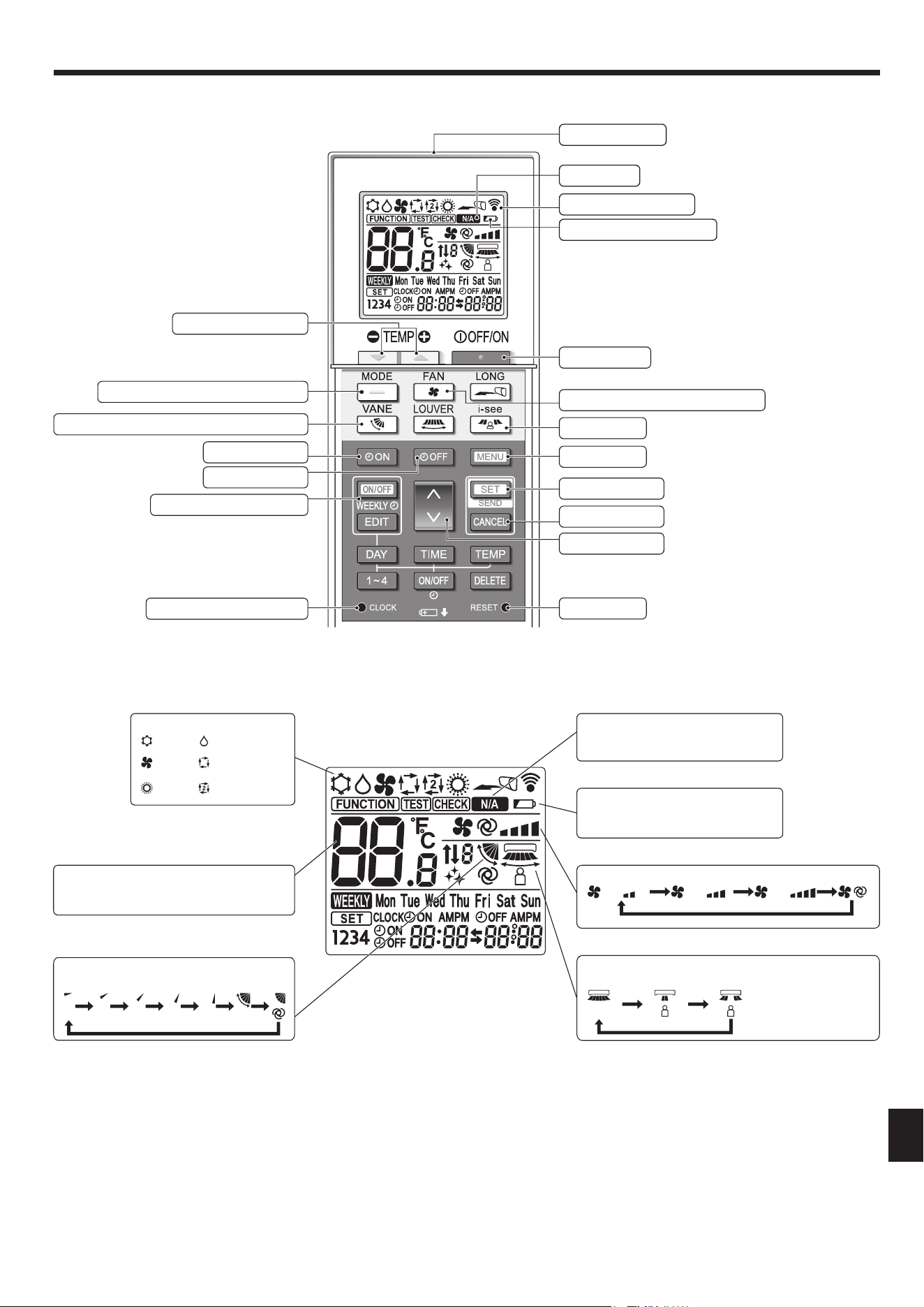
■ Wireless Remote-Controller
2. Parts Names
Temperature setting
The units of temperature can be changed. For
details, refer to the Installation Manual.
Not available
Appears when a non-supported func-
tion is selected.
Battery replacement indicator
Appears when the remaining battery
power is low.
Vane setting
Step 1 Step 2 Step 3 Step 4 Step 5 Swing Auto
Fan speed setting
3D i-see sensor (Air distribution)
Default Direct Indirect
When Direct or Indirect
is selected, the vane
setting is set to “Auto”.
Set Temperature buttons
Weekly timer ON/OFF button
Set Time button (Sets the time)
Airfl ow button (Changes up/down airfl ow direction)
Mode button (Changes operation mode)
Timer ON button
Timer OFF button
OFF/ON button
Fan Speed button (Changes fan speed)
SET/SEND button
CANCEL button
Up/Down buttons
Menu button
i-see button
Reset button
Remote controller display
Battery replacement indicator
Transmission area
Not available
Operation mode
Cool Dry
Fan
Auto
(single set point)
Heat
Auto*
(dual set point)
* The initial setting is necessary.
Refer to Installation manual.
VG79Y135H01_EN.indd 5VG79Y135H01_EN.indd 5 10/15/2562 BE 9:14 AM10/15/2562 BE 9:14 AM
6
3. Operation
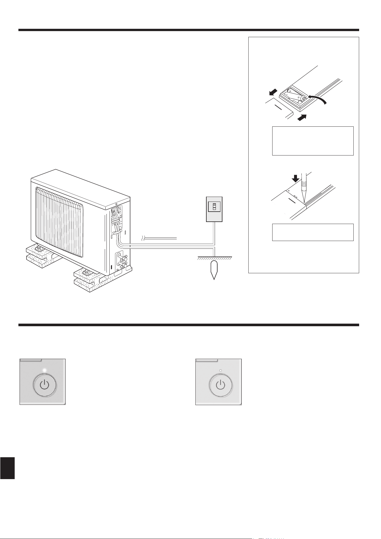
Battery installation/replacement
1. Remove the top cover, insert two LR6 AA bat-
teries, and then install the top cover.
2. Press the Reset button.
After battery installation/replacement,
please set clock.
Without setting clock, you cannot use a part
of function of remote controller.
■
About the operation method, refer to the operation manual that comes with each remote controller.
3.1. Turning ON/OFF
[ON] [OFF]
Press the [ON/OFF] button.
The ON/OFF lamp will light up in
green, and the operation will start.
When “LED lighting” is set to “No,” the
ON/OFF lamp will not light up.
Press the [ON/OFF] button again.
The ON/OFF lamp will come off, and
the operation will stop.
Note:
Even if you press the ON/OFF button immediately after shutting down the operation is progress, the air conditioner will not start for about 3
minutes.
This is to prevent the internal components from being damaged.
■ Outdoor unit
Power
Earth
Indoor-Outdoor
Connection wire
Ref. Pipes
2. Parts Names
1
2
3
Press the Reset button with an
object that has a narrow end.
Top cover
Notes (Only for wireless remote controller):
■ When using the wireless remote controller, point it towards the receiver on the indoor unit.
■ If the remote controller is operated within approximately 2 minutes after power is supplied to the
indoor unit, the indoor unit may beep twice as the unit is performing the initial automatic check.
■ The indoor unit beeps to confi rm that the signal transmitted from the remote controller has been
received. Signals can be received up to approximately 7 meters in a direct line from the indoor
unit in an area 45° to the left and right of the unit. However, illumination such as fl uorescent lights
and strong light can affect the ability of the indoor unit to receive signals.
■ If the operation lamp near the receiver on the indoor unit is blinking, the unit needs to be inspected.
Consult your dealer for service.
■ Handle the remote controller carefully! Do not drop the remote controller or subject it to strong
shocks. In addition, do not get the remote controller wet or leave it in a location with high humidity.
■ To avoid misplacing the remote controller, install the holder included with the remote controller on
a wall and be sure to always place the remote controller in the holder after use.
■ If the indoor unit beeps 4 times when you are using the wireless remote controller, switch the auto
mode setting to the AUTO (single set point) mode or AUTO (dual set point) mode.
For details, refer to the included Notice (A5 sheet) or the Installation Manual.
Two LR6 AA batteries
Insert the negative (–) end of each
battery fi rst. Install the batteries in
the correct directions (+, –)!
VG79Y135H01_EN.indd 6VG79Y135H01_EN.indd 6 10/15/2562 BE 9:14 AM10/15/2562 BE 9:14 AM
7
3. Operation
■
Operation status memory
Remote controller setting
Operation mode Operation mode before the power was turned off
Preset temperature Preset temperature before the power was turned off
Fan speed Fan speed before the power was turned off
■
Settable preset temperature range
Operation mode Preset temperature range
Cool/Dry 19 – 30 ºC
Heat 17 – 28 ºC
Auto 19 – 28 ºC
Fan/Ventilation Not settable
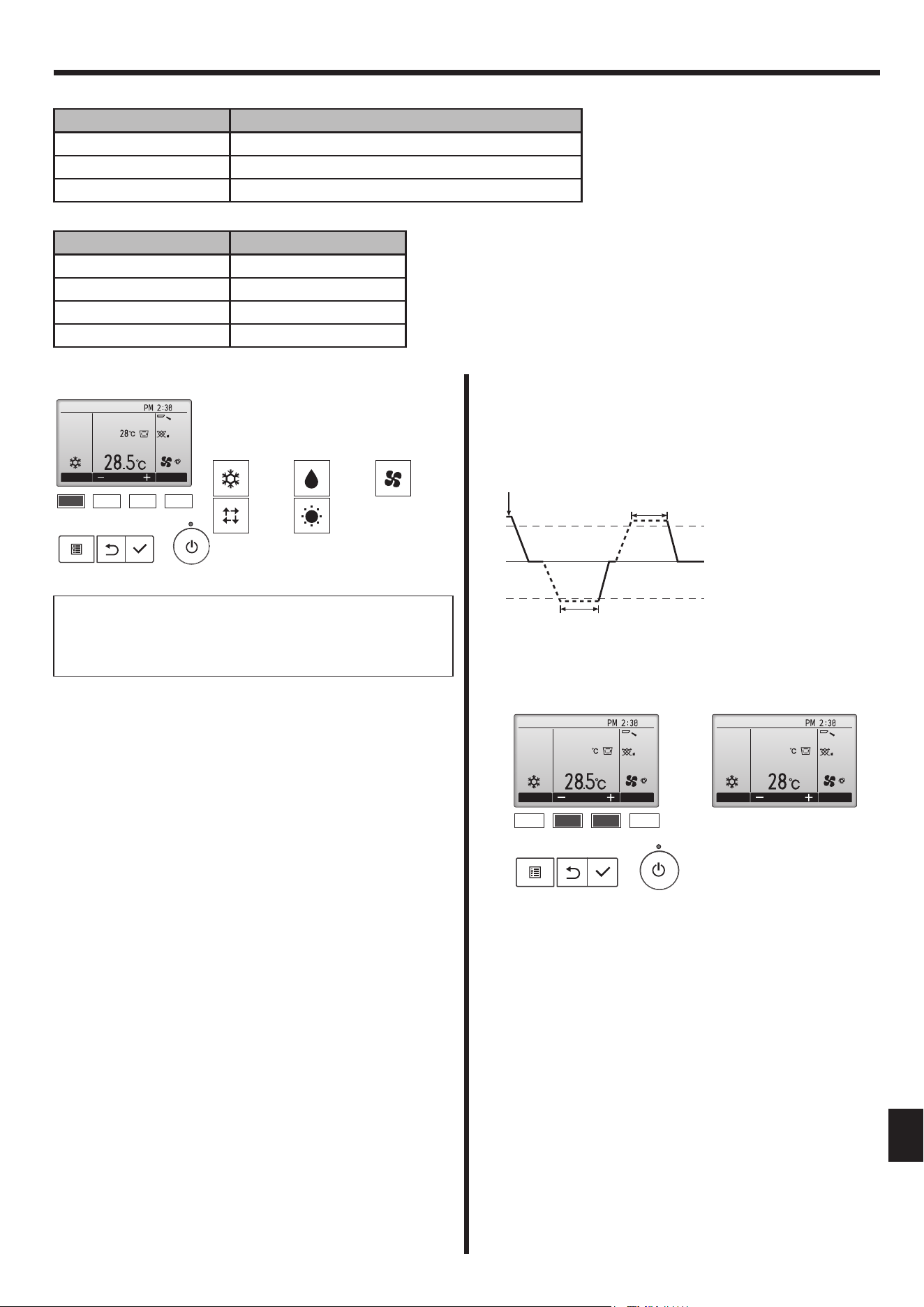
3.2. Mode Selection
Press the [F1] button to go through the
operation modes in the order of “Cool”,
“Dry”, “Fan”, “Auto”, and “Heat”. Select the
desired operation mode.
• Operation modes that are not available to
the connected indoor unit models will not
appear on the display.
Information for multi system air conditioner (Outdoor
unit: MXZ series)
► Multi system air conditioner (Outdoor unit: MXZ series) can
connect two or more indoor units with one outdoor unit. According
to the capacity, 2 or more units can operate simultaneously.
• When you try to operate 2 or more indoor units with 1 outdoor unit
simultaneously, one for the cooling and the other for heating, the
operation mode of the indoor unit that operates earlier is selected.
The other indoor units that will start the operation later cannot operate,
indicating an operation state in blinking.
In this case, please set all the indoor units to the same operation
mode.
• There might be a case that the indoor unit, which is operating in “Auto”
mode. Cannot change over to the operating mode “Cool”/“Heat” and
becomes a state of standby.
• When indoor unit starts the operation while the defrosting of outdoor
unit is being done, it takes a few minutes (max. about 15 minutes) to
blow out the warm air.
• In the heating operation, though indoor unit that does not operate may
get warm or the sound of refrigerant fl owing may be heard, they are
not malfunction. The reason is that the refrigerant continuously fl ows
into it.
Automatic operation
■
According to a set temperature, cooling operation starts if the room
temperature is too hot and heating operation starts if the room
temperature is too cold.
■
During automatic operation, if the room temperature changes and
remains 2 °C or more above the set temperature for 15 minutes, the
air conditioner switches to cooling mode. In the same way, if the room
temperature remains 2 °C or more below the set temperature for 15
minutes, the air conditioner switches to heating mode.
Cooling mode 15 minutes (switches from
heating to cooling)
Set temperature +2 °C
Set temperature
15 minutes (switches
from cooling to heating)
Set temperature -2 °C
Cool Dry Fan
Auto Heat
What the blinking mode icon means
The mode icon will blink when other indoor units in the same refriger-
ant system (connected to the same outdoor unit) are already operated
in a different mode. In this case, the rest of the unit in the same group
can only be operated in the same mode.
3.3. Temperature setting
<Cool, Dry, Heat, and Auto>
Press the [F2] button to decrease the preset temperature, and press the
[F3] button to increase.
• Refer to the table on 3-1 for the settable temperature range for
different operation modes.
• Preset temperature range cannot be set for Fan/Ventilation operation.
• Preset temperature will be displayed either in Centigrade in 0.5- or
1-degree increments, or in Fahrenheit, depending on the indoor unit
model and the display mode setting on the remote controller.
Example display
(Centigrade in 1-degree increments)
Cool
Room
AutoSet temp.
Mode Temp. Fan
Fri
F1 F2 F3 F4
28.5
F1 F2 F3 F4
Cool
Room
AutoSet temp.
Mode Temp. Fan
Fri
28
Cool
Room
AutoSet temp.
Mode Temp. Fan
Fri
VG79Y135H01_EN.indd 7VG79Y135H01_EN.indd 7 10/15/2562 BE 9:14 AM10/15/2562 BE 9:14 AM
8
<Exiting the Main menu screen>
Cool
Room
AutoSet temp.
Mode Temp. Fan
Fri
F1 F2 F3 F4
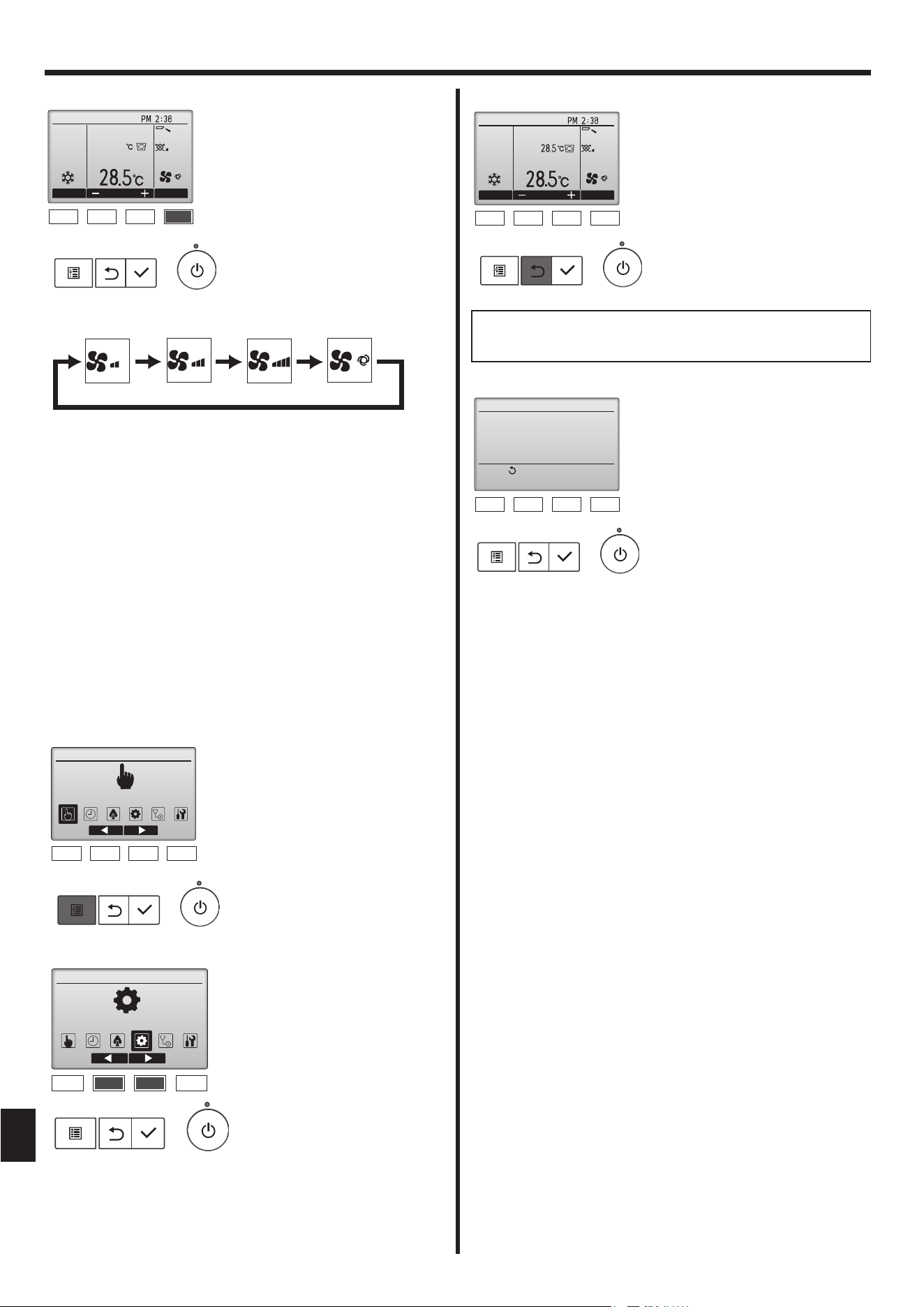
If no buttons are touched for 10 minutes, the screen will automatically
return to the Main display. Any settings that have not been saved will
be lost.
<Display of unsupported functions>
Title
Not available
Unsupported function
Return:
F1 F2 F3 F4
3.4. Fan speed setting
Cool
Room
AutoSet temp.
Mode Temp. Fan
Fri
28.5
F1 F2 F3 F4
Press the [F4] button to go through the fan speeds in the following order.
Auto
• The available fan speeds depend on the models of connected indoor
units.
Notes:
●
The number of available fan speeds depends on the type of unit
connected.
● In the following cases, the actual fan speed generated by the unit
will differ from the speed shown the remote controller display.
1. While the display is in “STAND BY” or “DEFROST” states.
2. When the temperature of the heat exchanger is low in the heat-
ing mode.
(e.g. immediately after heating operation starts)
3.In HEAT mode, when room temperature is higher than the tem-
perature setting.
4. In COOL mode, when room temperature is lower than the tem-
perature setting.
5. When the unit is in DRY mode.
3.5. Airfl ow direction setting
3.5.1 Navigating through the Main menu
<Accessing the Main menu>
Operation
Main Main menu
F1 F2 F3 F4
<Item selection>
Main Main menu
Initial setting
F1 F2 F3 F4
3. Operation
Press the [MENU] button on the
Main display.
The Main menu will appear.
Press [F2] to move the cursor left.
Press [F3] to move the cursor right.
The message at left will appear
if the user selects a function not
supported by the corresponding
indoor unit model.
Press the [RETURN] button to exit
the Main menu and return to the
Main display.
VG79Y135H01_EN.indd 8VG79Y135H01_EN.indd 8 10/15/2562 BE 9:14 AM10/15/2562 BE 9:14 AM
9
3. Operation
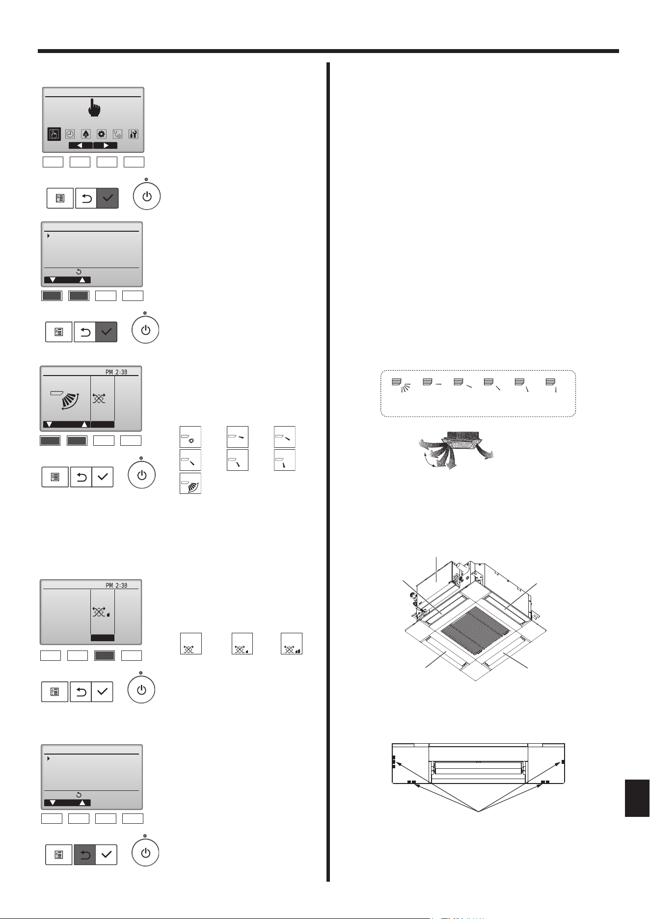
3.5.2 Vane·Vent. (Lossnay)
<Accessing the menu>
Operation
Main Main menu
F1 F2 F3 F4
Main menu:
Cursor
Operation
Vane·Louver·Vent. (Lossnay)
High power
Comfort
F1 F2 F3 F4
<Vane setting>
Fri
Swing Off
Vent.Vane
F1 F2 F3 F4
<Vent. setting>
Fri
Low
Vent.
F1 F2 F3 F4
<Returning to the Main menu>
Main menu:
Cursor
Operation
Vane·Louver·Vent. (Lossnay)
High power
Comfort
F1 F2 F3 F4
Select “Operation” from the Main
menu (refer to 3.5.1), and press the
[SELECT] button.
Select “Vane·Louver·Vent.
(Lossnay)” from the Operation
menu, and press the [SELECT]
button.
Press the [RETURN] button to go
back to the Operation menu.
Press the [F3] button to go through
the ventilation setting options in the
order of “Off”, “Low”, and “High”.
* Settable only when LOSSNAY unit
is connected.
Off Low High
Off Low High
•
The fan on some models of indoor
units may be interlocked with
certain models of ventilation units.
Reset 1
horizontal
2345
Note:
The outlet No. is indicated by the number of grooves on both ends of
each air outlet. Set the air direction while checking the information
shown on the remote controller display.
Horizontal airfl ow
Downward
Outlet No.4
Electric Component box
Outlet No.1
Air outlet identifi cation marks
Outlet No.3 Outlet No.2
Remote controller setting
The airfl ow direction of this outlet
is controlled by the airfl ow direc-
tion setting of remote controller.
Fixed
The airfl ow direction of this outlet is fi xed
in particular direction.
* When it is cold because of direct
airfl ow, the airfl ow direction can be
fi xed horizontally to avoid direct airfl ow.
< How to set the fi xed up/down air direction >
Notes:
● This function cannot be set depending on the outdoor unit to be
connected.
• For SLZ-M
.
FA-A series, only the particular outlet can be fi xed to certain
direction with the procedures below. Once fi xed, only the set outlet is
fi xed every time air conditioner is turned on. (Other outlets follow UP/
DOWN air direction setting of remote controller.)
■
Explanation of word
• “Refrigerant address No.” and “Unit No.” are the numbers given to
each air conditioner.
• “Outlet No.” is the number given to each outlet of air conditioner.
(Refer to the illustration below.)
• “Up/Down air direction” is the direction (angle) to fi x.
Press the [F1] or [F2] button to go
through the vane setting options:
"Auto", "Step 1", "Step 2", "Step 3",
"Step 4", "Step 5", and "Swing."
Select the desired setting.
Auto
Swing
Select "Swing" to move the vanes
up and down automatically.
When set to "Step 1" through "Step
5", the vane will be fi xed at the
selected angle.
Auto
Step 3
Swing
Step 1
Step 4
Step 2
Step 5
Notes:
●
During swing operation, the directional indication on the screen
does not change in sync with the directional vanes on the unit.
● Available directions depend on the type of unit connected.
●
In the following cases, the actual air direction will differ from the
direction indicated on the remote controller display.
1. While the display is in “STAND BY” or “DEFROST” states.
2. Immediately after starting heat mode (while the system is wait-
ing for the mode change to take effect).
3. In heat mode, when room temperature is higher than the tem-
perature setting.
VG79Y135H01_EN.indd 9VG79Y135H01_EN.indd 9 10/15/2562 BE 9:14 AM10/15/2562 BE 9:14 AM
10
3. Operation
■
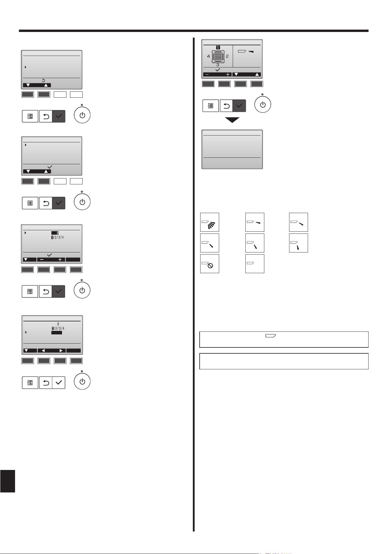
Manual vane angle (Wired remote controller)
Main menu:
Cursor
Operation
Vane·Louver·Vent. (Lossnay)
High power
Comfort
F1 F2 F3 F4
Setting display:
Cursor
Comfort
Manual vane angle
3D i-See sensor
F1 F2 F3 F4
Manual vane angle
Input display:
Cur. Address
Ref. address
Unit No.
Identify unit Check button
Check
F1 F2 F3 F4
Manual vane angle
Cur. Angle
Ref. address
Unit No.
Vane
4-way/2-way
Cursor
Input display:Angle button
F1 F2 F3 F4
Select “Comfort” from the Opertion
menu, and press the [SELECT]
button.
Select “Manual vane angle” with the
[F1] or [F2] button, and press the
[SELECT] button.
Move the cursor to “Ref. address”
or “Unit No.” with the [F1] button to
select.
Select the refrigerant address and
the unit number for the units to
whose vanes are to be fi xed, with
the [F2] or [F3] button, and press
the [SELECT] button.
• Ref. address: Refrigerant address
• Unit No.: 1, 2, 3, 4
Press the [F4] button to confi rm
the unit.
Select “Vane” with the [F1] button.
Select “4-way” or “2-way” with the
[F2] or [F3] button, and press the
[F4] button.
The current vane setting will apear.
Select the desired outlets from “1,”
“2,” “3,” “4,” or “1, 2, 3, 4 (all oulets)”
with the [F1] or [F2] button.
Press the [F3] or [F4] button to go
through the following options and
select the desired setting.
* Draft reduction
The airfl ow direction for this set-
ting is more horizontal than the
airfl ow direction for the “Step 1”
setting in order to reduce a drafty
feeling. The draft reduction can
be set for only 1 vane.
Note:
Do not set the draft reduction in an environment with high humidity.
Otherwise, condensation may form and drip.
Press the [SELECT] button to save the settings.
A screen will appear that indicates the setting information is being trans-
mitted.
The setting changes will be made to the selected outlet.
The screen will automatically return to the one shown above (step 5)
when the transmission is completed.
Make the settings for other outlets, following the same procedures.
■ Vane setting
Select:
Manual vane angle
Outlet Angle
Setting
Manual vane angle
F1 F2 F3 F4
No setting
Step 3
Step 1 Step 2
Step 5Step 4
All outlets
Draft
reduction*
If all outlets are selected,
will be displayed the next time the
unit goes into operation.
Navigating through the screens
• To return to the previous screen .......... [RETURN] button
VG79Y135H01_EN.indd 10VG79Y135H01_EN.indd 10 10/15/2562 BE 9:14 AM10/15/2562 BE 9:14 AM
11
3. Operation
* The draft reduction can be set for only 1 vane.
The setting is enabled only for the last vane that was set.
■
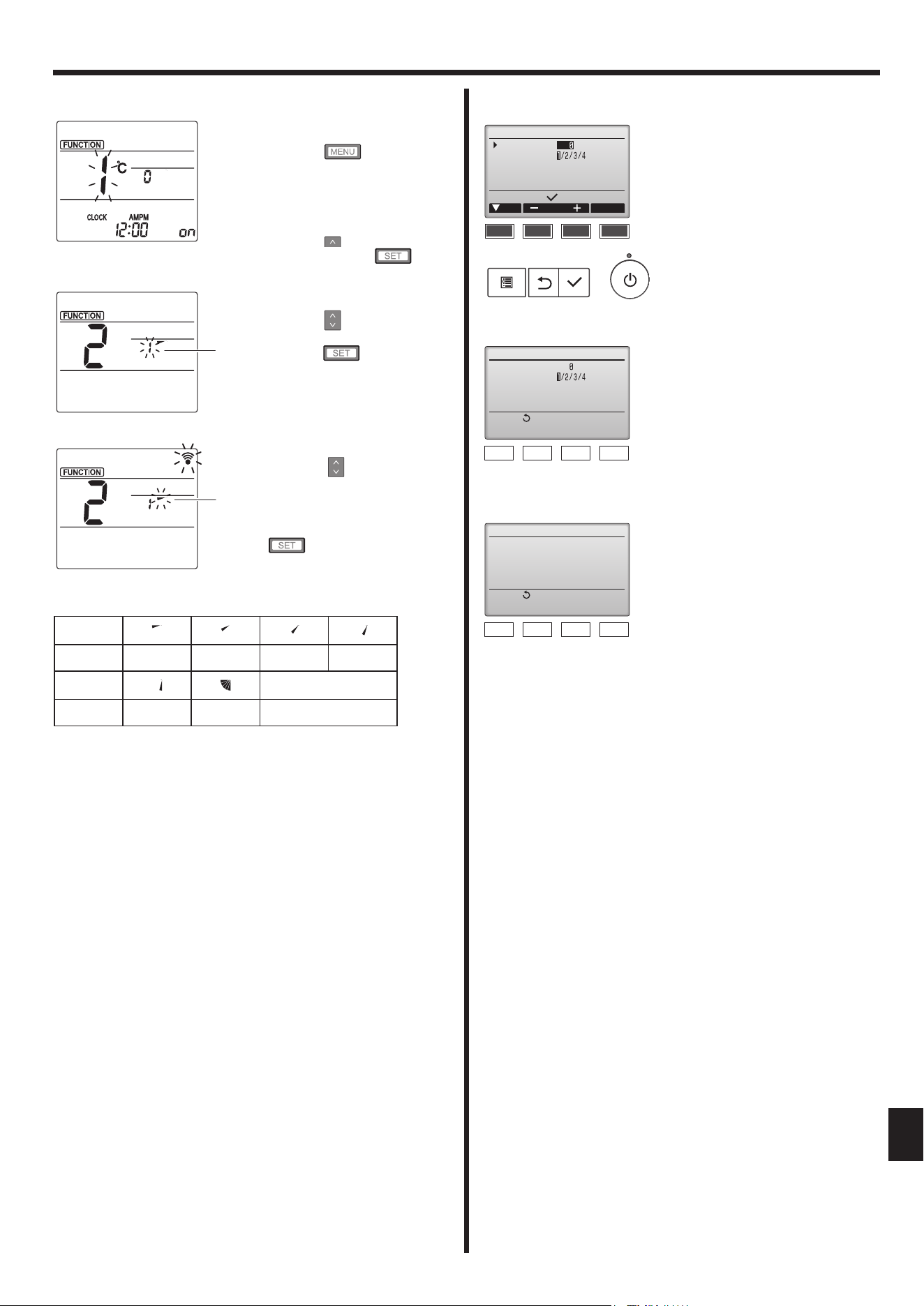
Manual vane angle (Wired remote controller)
A
B
Fig. 1
Fig. 2
Fig. 3
■ Confi rmation procedure (wired remote controller)
Manual vane angle
Input display:
Cur. Address Check
Ref. address
Unit No.
Identify unit Check button
F1 F2 F3 F4
Manual vane angle
Return:
No communication
Check Unit state.
F1 F2 F3 F4
Manual vane angle
Return:
Ref. address
Unit No.
Function setting for unit
with vane fully open.
F1 F2 F3 F4
1 First, confi rm by setting “Ref ad-
dress” to 0 and “Unit No.” to 1.
• Move the cursor to “Ref. address”
or “Unit No.” with the [F1] button
to select.
• Select the refrigerant address
and the unit number for the units
to whose vanes are to be fi xed,
with the [F2] or [F3] button, and
press the [SELECT] button.
• Ref. address: Refrigerant address
• Unit No.: 1, 2, 3, 4
Press the [F4] button to confi rm
the unit.
2 Change the “Unit No.” in order
and check each unit.
• Press the [F1] button to select
“Unit No.”.
Press the [F2] or [F3] button to
change the “Unit No.” to the unit
that you want to check, and then
press the [F4] button.
• After pressing the [F4] button,
wait approximately 15 seconds,
and then check the current state
of the air conditioner.
→ The vane is pointing down-
ward. → This air conditioner is
displayed on the remote controller.
→ All outlets are closed. →
Press the [RETURN] button and
continue the operation from the
beginning.
→ The messages shown to the
left are displayed. → The target
device does not exist at this
refrigerant address.
• Press the [RETURN] button to
return to the initial screen.
3 Change the “Ref. address” to the
next number.
• Refer to step 1 to change the
“Ref. address” and continue with
the confi rmation.
1 Going to the Manual vane setting
mode
Press the
button.
(Start this operation from the sta-
tus of remote controller display
turned off.)
“FUNCTION” is lighted and “1”
blinks. (Fig. 1)
Press the button to select “2”,
and then press the button.
2 Selecting the vane number (Fig.
2)
Press the
buttons to select
the vane number A, and then
press the button.
3 Setting the vane angle (Fig. 3)
Press the
buttons to select
the vane angle B.
Point the wireless remote control-
ler toward the receiver on the
indoor unit, and then press the
button.
Display
Setting Step 1 Step 2 Step 3 Step 4
Display
No display
Setting Step 5 No setting Draft reduction*
VG79Y135H01_EN.indd 11VG79Y135H01_EN.indd 11 10/15/2562 BE 9:14 AM10/15/2562 BE 9:14 AM
12
3. Operation
3.6. 3D i-see Sensor setting
Note:
This function cannot be set depending on the outdoor unit to be
connected.
3.6.1 3D i-see Sensor setting
Operation
Main Main menu
F1 F2 F3 F4
Cursor
Operation
Vane·Louver·Vent. (Lossnay)
High power
Comfort
Main menu:
F1 F2 F3 F4
Comfort
Cursor
Manual vane angle
3D i-See sensor
Setting display:
F1 F2 F3 F4
3D i-See sensor
Cursor
Setting display:
Air distribution
Energy saving option
Seasonal airflow
F1 F2 F3 F4
3.6.2 Air distribution
Air distribution
Input display:
Cur. Address Check
Ref. address
Unit No.
Identify unit Check button
F1 F2 F3 F4
Air distribution
Select:
Cur.
Ref. address
Unit No.
Auto vane
Direct/Indirect setting
All
Direct/Indirect
F1 F2 F3 F4
Direct/Indirect setting
: Direct
: Indirect
: Indirect
: Direct
Select:
Outlet
Angle
F1 F2 F3 F4
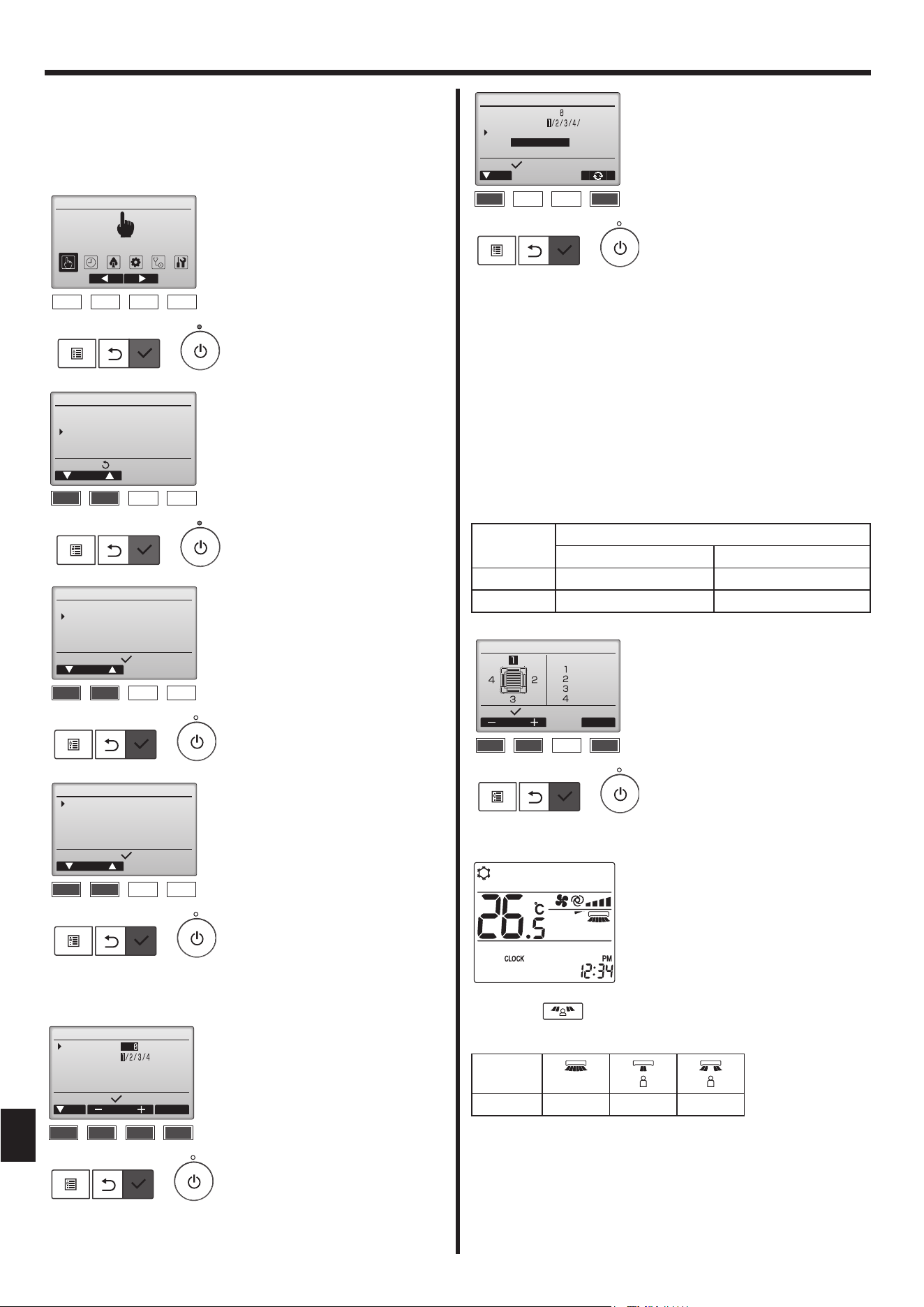
■ i-see button (Wireless remote controller)
1 Each time is pressed during operation, the setting changes in
the following order: OFF → Direct → Indirect.
Display
Setting OFF Direct Indirect
When the setting is changed from OFF to Direct or Indirect, the vane
setting changes to “Auto”. This setting is applied collectively to all of the
vanes.
1 Select “Operation” from the Main
menu, and press the [SELECT]
button.
2 Select “Comfort” from the
Operation menu, and press the
[SELECT] button.
3 Select “3D i-See sensor” with the
[F1] or [F2] button, and press the
[SELECT] button.
4 Select the desired menu with the
[F1] or [F2] button, and press the
[SELECT] button.
• Air distribution
Select the airfl ow direction
control method when the airfl ow
direction is set to “Auto”.
• Energy saving option
Operates the energy-save mode
according to whether persons are
detected in the room by the 3D
i-see Sensor.
• Seasonal airfl ow
When the thermostat turns off,
the fan and the vanes operate
according to the control settings.
1 Move the cursor to “Ref. address”
or “Unit No.” with the [F1] button
to select.
Select the refrigerant address
and the unit number for the units
to whose vanes are to be fi xed,
with the [F2] or [F3] button, and
press the [SELECT] button.
•
Ref. address: Refrigerant address
• Unit No.: 1, 2, 3, 4
Press the [F4] button to confi rm
the unit.
The vane of only the target
indoor unit is pointing downward.
2 Select the menu with the [F4]
button.
Default → Area → Direct/Indirect
→ Default…
Default: The vanes move the
same as during normal operation.
“Area”*: The vanes move to the
down airfl ow direction toward ar-
eas with a high fl oor temperature
during cooling mode and toward
areas with a low fl oor tem-
perature during heating mode.
Otherwise, the vanes move to the
horizontal airfl ow direction.
“Direct/Indirect”*: The vanes
automatically move relative to
the areas where persons are
detected.
The vanes operate as indicated
in the following table.
* In order to enable this function,
the airfl ow direction must be set
to “Auto”.
3 When Direct/Indirect is selected,
set each air outlet.
Select the air outlet with the
[F1] or [F2] button, and change
the setting with the [F4] button.
After changing the settings for
all of the air outlets, press the
[SELECT] button to save the set-
tings.
Vane setting
Direct Indirect
Cooling horizontal → swing keep horizontal
Heating keep downward downward → horizontal
VG79Y135H01_EN.indd 12VG79Y135H01_EN.indd 12 10/15/2562 BE 9:14 AM10/15/2562 BE 9:14 AM
13
3. Operation
3.6.3 Energy saving option
Energy saving option
Select:
No occupancy energy save
Cooling/Heating
F1 F2 F3 F4
Energy saving option
Select:
Room occupancy energy save
Cooling/Heating
F1 F2 F3 F4
Energy saving option
Cursor
Setting display:
No occupancy energy save
Room occupancy energy save
No occupancy Auto-OFF
F1 F2 F3 F4
Energy saving option
Select:
Time
No occupancy Auto-OFF
min.120
F1 F2 F3 F4
18:47 Thu
Shut down by
No Occupancy Auto-OFF
31/Dec AM12:59
F1 F2 F3 F4
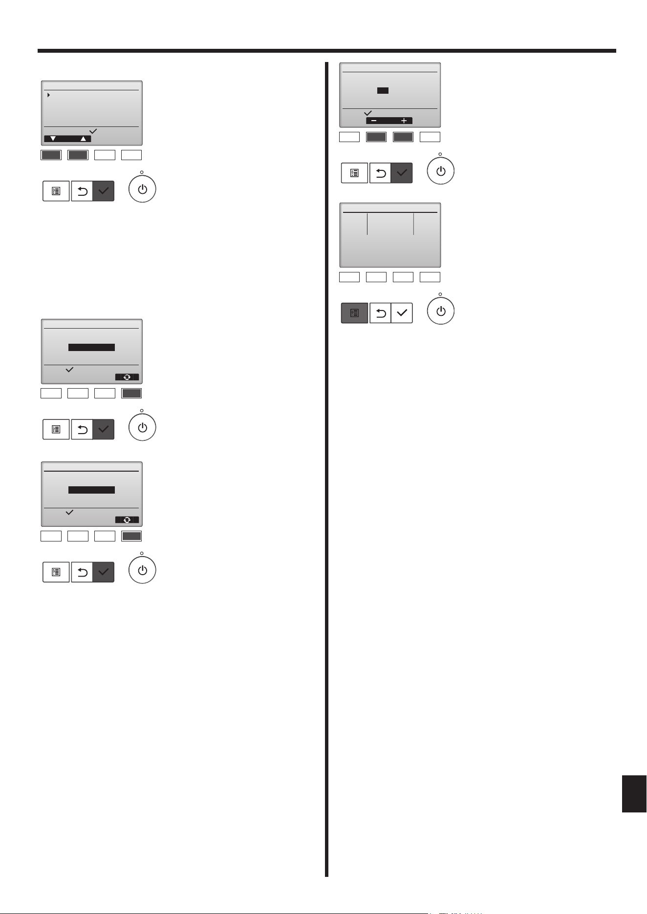
1 Select the desired menu with the
[F1] or [F2] button.
No occupancy energy save
If there are no persons in the
room for 60 minutes or more,
energy-saving operation equal to
2 °C is performed.
Room occupancy energy save
If the occupancy rate decreases
to approximately 30% of the
maximum occupancy rate,
energy-saving operation equal to
1 °C is performed.
No occupancy Auto-OFF
If there are no persons in the
room for the set amount of time
(60–180 minutes), the operation
is automatically stopped.
2 When No occupancy energy
save or Room occupancy energy
save is selected
Select the setting with the [F4]
button.
OFF → Cooling only → Heat-
ing only → Cooling/Heating →
OFF…
After changing the setting, press
the [SELECT] button to save the
setting.
OFF: The function is disabled.
Cooling only: The function is ena-
bled only during cooling mode.
Heating only: The function is ena-
bled only during heating mode.
Cooling/Heating: The function
is enabled during both cooling
mode and heating mode.
3 When No occupancy Auto-OFF is
selected
Set the time with the [F3] or [F4]
button.
---: The setting is disabled (the
operation will not stop automati-
cally).
60–180: The time can be set in
10-minute increments.
4 The message at left will appear
if the operation was stopped au-
tomatically by the No occupancy
Auto-OFF setting.
VG79Y135H01_EN.indd 13VG79Y135H01_EN.indd 13 10/15/2562 BE 9:14 AM10/15/2562 BE 9:14 AM
14
Notes:
Any person at the following places cannot be detected.
● Along the wall on which the air conditioner is installed
● Directly under the air conditioner
● Where any obstacle, such as furniture, is between the person and
the air conditioner
A person may not be detected in the following situations.
● Room temperature is high.
● A person wears heavy clothes and his/her skin is not exposed.
● A heating element of which temperature changes signifi cantly is
present.
● Some heat sources, such as a small child or pet, may not be
sensed.
● A heat source does not move for a long time.
The 3D i-see Sensor operates once approximately every 3 minutes
to measure the fl oor temperature and detect persons in the room.
● The intermittent operating sound is a normal sound produced
when the 3D i-see Sensor is moving.
3.7. Ventilation
For LOSSNAY combination
■ The following 2 patterns of operation is available.
• Run the ventilator together with indoor unit.
• Run the ventilator independently.
Notes: (for wireless remote controller)
● Running the ventilator independently is not available.
● No indication on the remote controller.
3. Operation
4. Timer
3.6.4 Seasonal airfl ow function
Seasonal airflow
Select:
Seasonal airflow
Cooling/Heating
F1 F2 F3 F4
B
A
D
C
Fig. 1
Fig. 2
Fig. 3
Fig. 4
Fig. 5
1 Select the setting with the [F4]
button.
OFF → Cooling only → Heat-
ing only → Cooling/Heating →
OFF…
After changing the setting, press
the [SELECT] button to save the
setting.
OFF: The function is disabled.
Cooling only: When the thermo-
stat turns off during cooling
mode, the vanes move up and
down.
Heating only: When the ther-
mostat turns off during heating
mode, the vanes move to the
horizontal airfl ow direction to
circulate the air.
Cooling/Heating: The function
is enabled during both cooling
mode and heating mode.
* In order to enable this function,
the airfl ow direction must be set
to “Auto”.
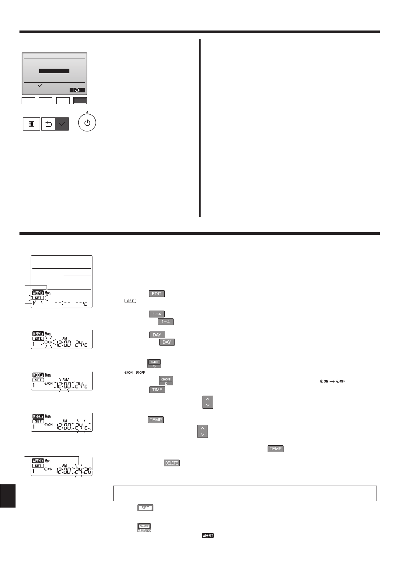
Weekly schedule (Wireless remote controller)
■ The weekly schedule can be set to four operation patterns for each day of the week. The settings include the
on and off times and the set temperature.
<Editing mode>
1. Switching to the editing mode
1 Press the
button when the unit is operating or stopped.
blinks. (Fig. 1)
2. Selecting the setting pattern
1 Press the button to select the setting pattern number.
Each time the button is pressed, the pattern number A changes in the following order: 1 → 2 → 3 → 4.
3. Selecting the day of the week
1 Press the button to select the day of the week to set.
Each time the
button is pressed, the day of the week B changes in the following order: Mon → Tue
→ Wed → Thu → Fri → Sat → Sun → All days.
4. Selecting the operation settings
1 Push the button to select the operation on or off setting. (Fig. 2)
( ) is lighted.
Each time the button is pressed, the setting changes in the following order: .
2 Press the
button to select the operation time. (Fig. 3)
The operation time blinks.
Set the operation time using the
buttons.
• The operation time can be set in 10-minute increments.
3 Push the
button to select the set temperature. (Fig. 4)
The set temperature blinks.
Set the temperature using the buttons.
• When setting the off operation, the temperature cannot be set.
When the AUTO (dual set point) mode is enabled, press the button to switch between the upper limit
C and the lower limit D. (Fig. 5)
4 By pressing the button, the pattern number settings for the displayed day of the week are deleted.
5 Repeat steps 2–4 to select the settings for each day of the week.
<Transmitting the settings>
Press the
button.
<Enabling the weekly schedule>
Press the
button.
The weekly schedule operates when is on.
• The weekly schedule does not function when the On/Off timer is enabled.
The weekly schedule operates when all of the On/Off timer settings have been executed.
■ Timer functions are different by each remote controller.
■ For details on how to operate the remote controller, refer to the appropriate operation manual included with each remote controller.
Point the transmission area of the wireless remote controller towards the receiver on the indoor unit and
operate the controller. Confi rm that the indoor unit beeps 7 times.
VG79Y135H01_EN.indd 14VG79Y135H01_EN.indd 14 10/15/2562 BE 9:14 AM10/15/2562 BE 9:14 AM
15
5. Care and Cleaning
A
B
D
C
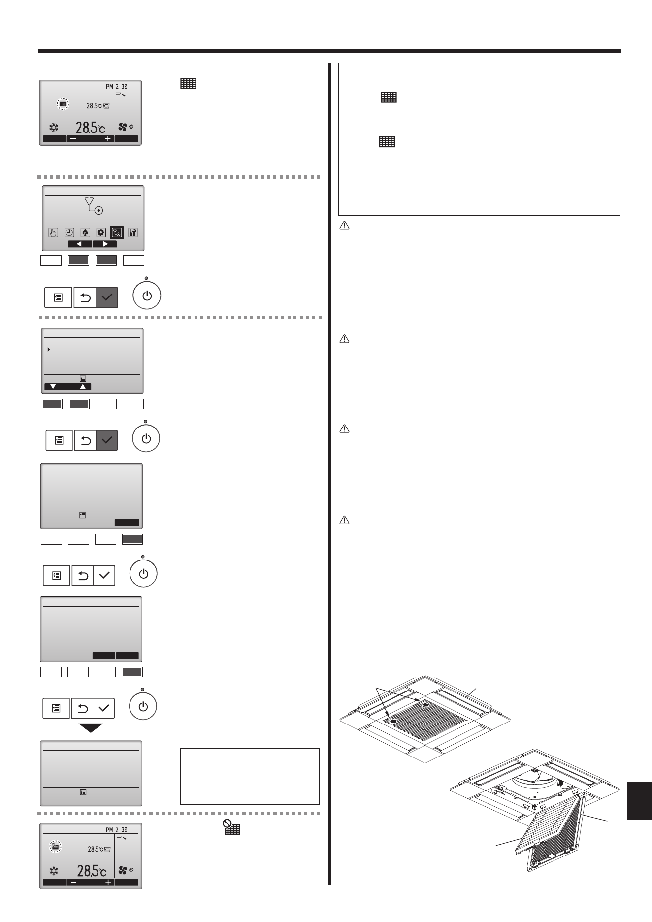
Main menu:
Filter information
Reset
Press Reset button after
filter cleaning.
F1 F2 F3 F4
Select “OK” with the [F4] button.
A confi rmation screen will appear.
Navigating through the screens
• To go back to the Main menu
....................... [MENU] button
• To return to the previous screen
....................... [RETURN] button
Cool
Room
AutoSet temp.
Mode Temp. Fan
Fri
Filter information
Filter information
OK
Cancel
Reset filter sign?
Filter sign reset
Main menu:
F1 F2 F3 F4
When the is displayed on the
Main display in the Full mode, the
system is centrally controlled and
the fi lter sign cannot be reset.
If two or more indoor units are connected, fi lter cleaning timing for each
unit may be different, depending on the fi lter type.
The icon
will appear when the fi lter on the main unit is due for
cleaning.
When the fi lter sign is reset, the cumulative operation time of all units
will be reset.
The icon
is scheduled to appear after a certain duration of opera-
tion, based on the premise that the indoor units are installed in a space
with ordinary air quality. Depending on the air quality, the fi lter may
require more frequent cleaning.
The cumulative time at which filter needs cleaning depends on the
model.
• This indication is not available for wireless remote controller.
Caution:
• Ask authorized people to clean the fi lter.
► Cleaning the fi lters
• Clean the fi lters using a vacuum cleaner. If you do not have a vacuum
cleaner, tap the fi lters against a solid object to knock off dirt and dust.
• If the fi lters are especially dirty, wash them in lukewarm water. Take care
to rinse off any detergent thoroughly and allow the fi lters to dry completely
before putting them back into the unit.
Caution:
• Do not dry the fi lters in direct sunlight or by using a heat source,
such as an electric heater: this may warp them.
• Do not wash the fi lters in hot water (above 50°C), as this may warp
them.
• Make sure that the air fi lters are always installed. Operating the unit
without air fi lters can cause malfunction.
Caution:
• Before you start cleaning, stop operation and turn OFF the power
supply.
• Indoor units are equipped with fi lters to remove the dust of sucked-
in air. Clean the fi lters using the methods shown in the following
sketches.
► Filter removal
Caution:
• In removing the fi lter, precautions must be taken to protect your
eyes from dust. Also, if you have to climb up on a stool to do the
job, be careful not to fall.
• When the fi lter is removed, do not touch the metallic parts inside
the indoor unit, otherwise injury may result.
■ SLZ-M·FA-A
1 Slide the levers on the intake grille in the direction indicated by the
arrow and it should open.
2 Open the intake grille.
3 Release the knob on the center edge of the intake grille and pull the
fi lter forward to remove the fi lter.
A Intake grille levers B Grille C Intake grille D Filter
Cursor
Maintenance menu
Error information
Filter information
Cleaning
F1 F2 F3 F4
Main menu:
■ Filter information
Cool
Room
AutoSet temp.
Mode Temp. Fan
Fri
F1 F2 F3 F4
Main Main menu
Maintenance
will appear on the Main display
in the Full mode when it is time to
clean the fi lters.
Wash, clean, or replace the fi lters
when this sign appears.
Refer to the indoor unit Instructions
Manual for details.
Select “Maintenance” from the Main
menu, and press the [SELECT]
button.
Select “Filter information” from the
Maintenance menu, and press the
[SELECT] button.
Press the [F4] button to reset fi lter
sign.
Refer to the indoor unit Instructions
Manual for how to clean the fi lter.
VG79Y135H01_EN.indd 15VG79Y135H01_EN.indd 15 10/15/2562 BE 9:14 AM10/15/2562 BE 9:14 AM
16
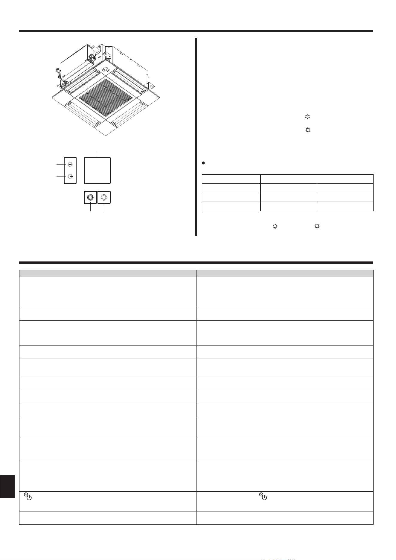
When the remote controller cannot be used
When the batteries of the remote controller run out or the remote
controller malfunctions, the emergency operation can be done using the
emergency buttons on the grille.
A
DEFROST/STAND BY lamp
B
Operation lamp
C
Emergency operation cooling switch
D
Emergency operation heating switch
E
Receiver
Starting operation
• To operate the cooling mode, press the
button
C
for more than 2
seconds.
• To operate the heating mode, press the button
D
for more than 2
seconds.
• Lighting of the Operation lamp
B
means the start of operation.
Notes:
Details of emergency mode are as shown below.
Details of EMERGENCY MODE are as shown below.
Operation mode COOL HEAT
Set temperature 24°C 24°C
Fan speed High High
Airfl ow direction Horizontal Downward 4 (5)
Stopping operation
• To stop operation, press the
button C or the button D for more than
2 seconds.
E
B
A
D C
6. Emergency Operation for Wireless Remote-controller
Having trouble? Here is the solution. (Unit is operating normally.)
Air conditioner does not heat or cool well.
■ Clean the fi lter. (Airfl ow is reduced when the fi lter is dirty or clogged.)
■ Check the temperature adjustment and adjust the set temperature.
■ Make sure that there is plenty of space around the outdoor unit. Is the
indoor unit air intake or outlet blocked?
■ Has a door or window been left open?
When heating operation starts, warm air does not blow from the indoor
unit soon.
■ Warm air does not blow until the indoor unit has suffi ciently warmed up.
During heating mode, the air conditioner stops before the set room tem-
perature is reached.
■ When the outdoor temperature is low and the humidity is high, frost
may form on the outdoor unit. If this occurs, the outdoor unit performs a
defrosting operation. Normal operation should begin after approximately
10 minutes.
During cooling mode, the air conditioner stops when the set room tem-
perature is reached.
■ For SLZ-M·FA-A series, when the set room temperature is reached
during cooling mode, the fan operates at the lowest speed.
Airfl ow direction changes during operation or airfl ow direction cannot be set.
■ During heating mode, the vanes automatically move to the horizontal
airfl ow direction when the airfl ow temperature is low or during defrosting
mode.
When the airfl ow direction is changed, the vanes always move up and down
past the set position before fi nally stopping at the position.
■ When the airfl ow direction is changed, the vanes move to the set position
after detecting the base position.
A fl owing water sound or occasional hissing sound is heard.
■ These sounds can be heard when refrigerant is fl owing in the air condi-
tioner or when the refrigerant fl ow is changing.
A cracking or creaking sound is heard.
■ These sounds can be heard when parts rub against each due to expan-
sion and contraction from temperature changes.
The room has an unpleasant odor.
■ The indoor unit draws in air that contains gases produced from the walls,
carpeting, and furniture as well as odors trapped in clothing, and then
blows this air back into the room.
A white mist or vapor is emitted from the indoor unit.
■ If the indoor temperature and the humidity are high, this condition may
occur when operation starts.
■ During defrosting mode, cool airfl ow may blow down and appear like a
mist.
Water or vapor is emitted from the outdoor unit.
■ During cooling mode, water may form and drip from the cool pipes and
joints.
■ During heating mode, water may form and drip from the heat exchanger.
■ During defrosting mode, water on the heat exchanger evaporates and
water vapor may be emitted.
“
” appears in the remote controller display.
■ During central control, “
” appears in the remote controller display and
air conditioner operation cannot be started or stopped using the remote
controller.
When restarting the air conditioner soon after stopping it, it does not oper-
ate even though the ON/OFF button is pressed.
■ Wait approximately three minutes.
(Operation has stopped to protect the air conditioner.)
7. Trouble Shooting
VG79Y135H01_EN.indd 16VG79Y135H01_EN.indd 16 10/15/2562 BE 9:14 AM10/15/2562 BE 9:14 AM
17
7. Trouble Shooting
Having trouble? Here is the solution. (Unit is operating normally.)
Air conditioner operates without the ON/OFF button being pressed.
■ Is the on timer set?
Press the ON/OFF button to stop operation.
■ Is the air conditioner connected to a central remote controller?
Consult the concerned people who control the air conditioner.
■ Does “
” appear in the remote controller display?
Consult the concerned people who control the air conditioner.
■ Has the auto recovery feature from power failures been set?
Press the ON/OFF button to stop operation.
Air conditioner stops without the ON/OFF button being pressed.
■ Is the off timer set?
Press the ON/OFF button to restart operation.
■ Is the air conditioner connected to a central remote controller?
Consult the concerned people who control the air conditioner.
■ Does “
” appear in the remote controller display?
Consult the concerned people who control the air conditioner.
Remote controller timer operation cannot be set.
■ Are timer settings invalid?
If the timer can be set,
or appears in the remote controller display.
“PLEASE WAIT” appears in the remote controller display.
■ The initial settings are being performed. Wait approximately 3 minutes.
An error code appears in the remote controller display.
■ The protection devices have operated to protect the air conditioner.
■ Do not attempt to repair this equipment by yourself.
Turn off the power switch immediately and consult your dealer. Be sure
to provide the dealer with the model name and information that appeared
in the remote controller display.
Draining water or motor rotation sound is heard.
■ When cooling operation stops, the drain pump operates and then stops.
Wait approximately 3 minutes.
The vanes do not move or the indoor unit does not respond to input from
the wireless remote controller.
■ The junction wire connectors of the vane motor and signal receiver may
not be connected correctly. Have an installer check the connections. (The
colors of the male and female sections of the junction wire connectors
must match.)
Noise is louder than specifi cations.
■ The indoor operation sound level is affected by the acoustics of the
particular room as shown in the following table and will be higher than
the noise specifi cation, which was measured in an echo-free room.
High sound-
absorbing
rooms
Normal rooms
Low sound-
absorbing
rooms
Location
examples
Broadcasting
studio, music
room, etc.
Reception
room, hotel
lobby, etc.
Offi ce, hotel
room
Noise levels 3 to 7 dB 6 to 10 dB 9 to 13 dB
Nothing appears in the wireless remote controller display, the display
is faint, or signals are not received by the indoor unit unless the remote
controller is close.
■ The batteries are low.
Replace the batteries and press the Reset button.
■ If nothing appears even after the batteries are replaced, make sure that
the batteries are installed in the correct directions (+, –).
The operation lamp near the receiver for the wireless remote controller on
the indoor unit is fl ashing.
■ The self diagnosis function has operated to protect the air conditioner.
■ Do not attempt to repair this equipment by yourself.
Turn off the power switch immediately and consult your dealer. Be sure
to provide the dealer with the model name.
The wireless remote controller does not operate (the indoor unit beeps
4 times).
■ Switch the auto mode setting to the AUTO (single set point) mode or
AUTO (dual set point) mode. For details, refer to the included Notice
(A5 sheet) or the Installation Manual.
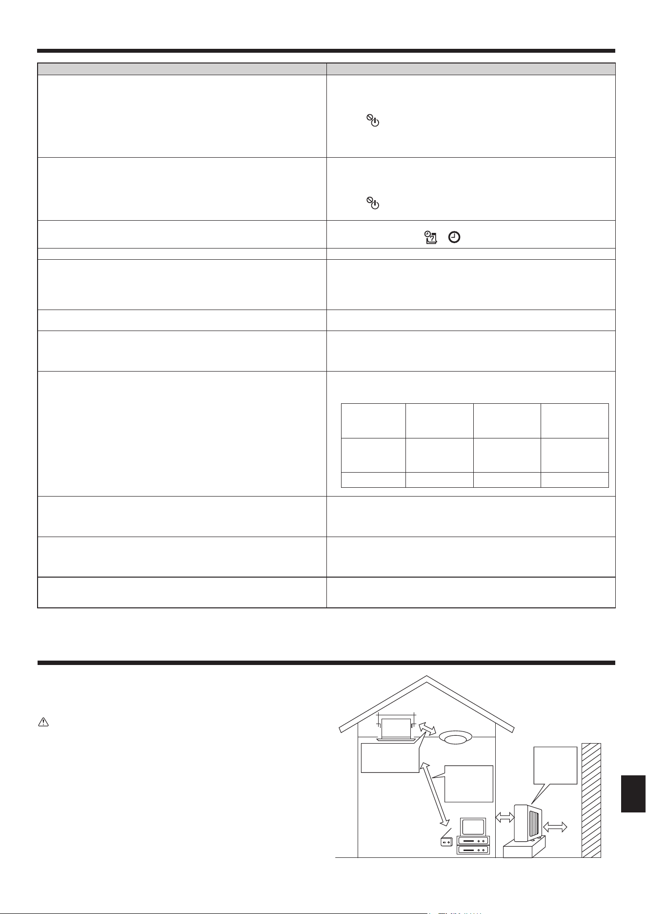
Installation place
Avoid installing the air conditioner in the following places.
• Where fl ammable gas could leak.
Caution:
Do not install the unit where fl ammable gas could leak.
If gas leaks and collects around the unit, it may cause an explosion.
• Where there is much machine oil.
• Salty place such as the seaside.
• Where sulfi de gas is generated such as a hot spring.
• Where there is oil splashing or much oily smoke.
8. Installation, relocation and inspection
Inverter type
fl uorescent lamp
To prevent the effect
of a fl uorescent lamp,
keep it away as far
apart as possible.
To prevent picture
distortion or
noise, keep 1 m
or more apart.
Radio
100 mm or
more
400 mm
or more
Well-
ventilated dry
place
Wall, etc.
VG79Y135H01_EN.indd 17VG79Y135H01_EN.indd 17 10/15/2562 BE 9:14 AM10/15/2562 BE 9:14 AM
18
8. Installation, relocation and inspection
Warning:
If the air conditioner operates but does not cool or heat (depending on model) the room, consult your dealer since there may be a refrigerant
leak. Be sure to ask the service representative whether there is refrigerant leakage or not when repairs are carried out.
The refrigerant charged in the air conditioner is safe. Refrigerant normally does not leak, however, if refrigerant gas leaks indoors, and comes
into contact with the fi re of a fan heater, space heater, stove, etc., harmful substances will be generated.
Electrical work
• Provide an exclusive circuit for power supply of the air conditioner.
• Be sure to observe the breaker capacity.
Warning:
• The customer should not install this unit. If the unit is installed incorrectly, fi re, electric shock, injury due to a falling unit, water leakage, etc.
may result.
• Do not connect using branched outlet or an extension cord, and do not attach many loads to one electric outlet.
A fi re or electric shock may result from poor contact, poor insulation, exceeding the permissible current, etc.
Consult your dealer.
Caution:
• Apply grounding
Do not connect a grounding wire to a gas pipe, water pipe, lightning rod or ground wire of a telephone.
If a grounding is incorrect, it may cause an electric shock.
• Install an earth leakage breaker depending on the place where the air conditioner is to be installed (humid place, etc.).
If the earth leakage breaker is not installed, it may cause an electric shock.
Inspection and maintenance
• When the air conditioner is used for several seasons, the capacity may be lowered due to dirt inside the unit.
• Depending upon the conditions of use, an odor may be generated or dirt, dust, etc. may prevent proper drainage.
• It is recommended to apply inspection and maintenance (charged) by a specialist in addition to normal maintenance. Consult your dealer.
Also consider operation sound
• Do not put an object around the air outlet of the outdoor unit. It may cause lowering of capacity or increase operating sound.
• If abnormal sound is heard during operation, consult your dealer.
Relocation
• When the air conditioner is to be removed or reinstalled because of rebuilding, moving, etc., special techniques and work are required.
Warning:
Repair or relocation should not be done by the customer.
If this is done incorrectly, it may cause a fi re, electric shock, injury by dropping of the unit, water leakage, etc. Consult your dealer.
Disposal
• To dispose of this product, consult your dealer.
If you have any question, consult your dealer.
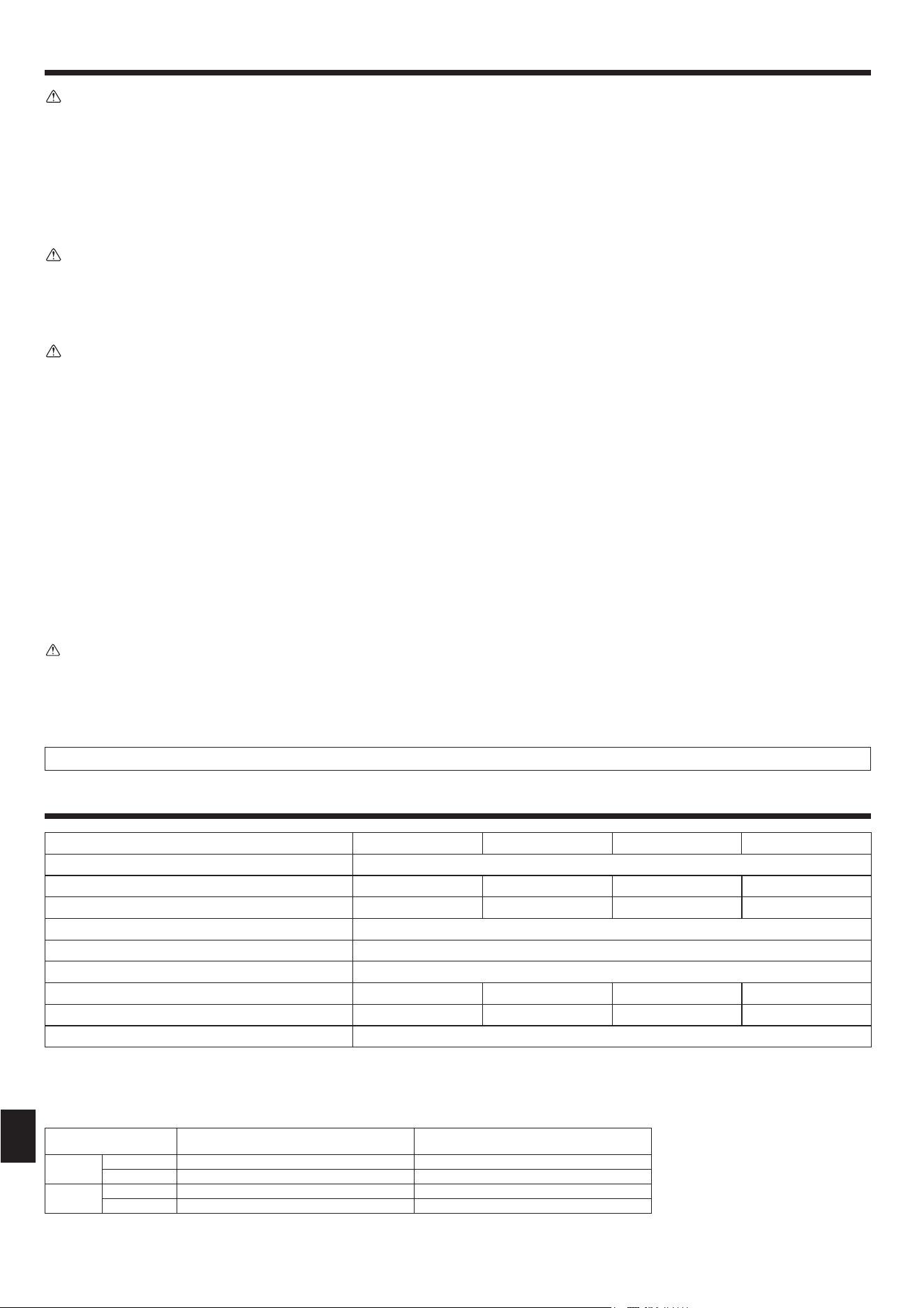
Notes: 1. This fi gure ( ) indicates GRILLE’s.
2. Specifi cations subject to change without notice.
Guaranteed operating range
Indoor Outdoor
Cooling
Upper limit 32°C DB, 23°C WB 46°C DB, – / 52°C DB, – *1
Lower limit 21°C DB, 15°C WB -10°C DB, – / -15°C DB, – *1
Heating
Upper limit 27°C DB, – 24°C DB, 18°C WB
Lower limit 20°C DB, – -10°C DB, -11°C WB
*1 Depend on outdoor unit.
Units should be installed by licensed electric contractor accordingly to local code requirement.
9. Specifi cations
Model SLZ-M25FA-A SLZ-M35FA-A SLZ-M50FA-A SLZ-M60FA-A
Power Supply (Voltage <V>, Frequency <Hz>) ~/N, 230V, 50Hz
Rated Input (Indoor only) <kW> 0.02 0.03 0.03 0.04
Rated Current (Indoor only) <A> 0.20 0.32 0.32 0.43
Dimension (Height) <mm> 245 (10)
Dimension (Width) <mm> 570 (625)
Dimension (Depth) <mm> 570 (625)
Fan airfl ow rate (Low-Middle-High) <m
3
/min> 6.5 - 7.5 - 8.5 6.5 - 9.0 - 11.5 7.0 - 9.0 - 11.5 7.5 - 11.5 - 13.0
Noise level (Low-Middle-High) <dB> 25 - 28 - 31 25 - 33 - 39 27 - 34 - 39 32 - 40 - 43
Net weight <kg> 15 (3)
VG79Y135H01_EN.indd 18VG79Y135H01_EN.indd 18 10/15/2562 BE 9:14 AM10/15/2562 BE 9:14 AM
Printed in Thailand
HEAD OFFICE: TOKYO BUILDING, 2-7-3, MARUNOUCHI, CHIYODA-KU, TOKYO 100-8310, JAPAN
VG79Y135H01
This product is designed and intended for use in the residential,
commercial and light-industrial environment.
Please be sure to put the contact address/telephone number on
this manual before handing it to the customer.
VG79Y135H01_Cover.indd 2VG79Y135H01_Cover.indd 2 9/9/2562 BE 2:46 PM9/9/2562 BE 2:46 PM