2
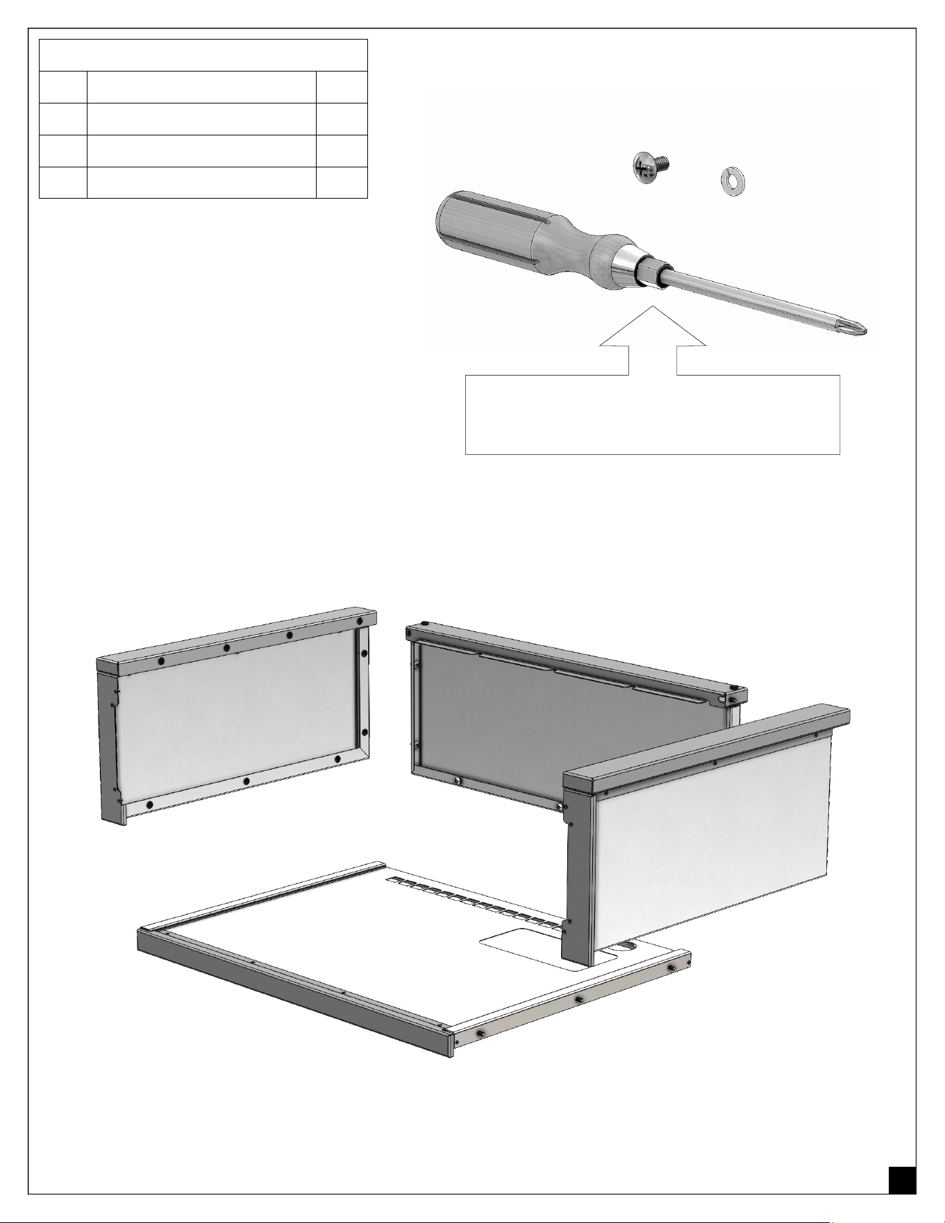
COMPONENTS INCLUDED IN THIS KIT:
ITEM DESCRIPTION: QTY:
A 1/4-20 x 1/2” SCREW 16
B 1/4” LOCK WASHER 16
~ PANELS AS SHOWN BELOW 4
A
B
ITEM NOT INCLUDED AND REQUIRED
FOR ASSEMBLY OF THIS UNIT:
STANDARD #2 PHILIPS SCREWDRIVER
LEFT PANEL
510-0651
RIGHT PANEL
510-0650
BOTTOM PANEL:
510-0653 - 26IN
510-0655 - 32IN
510-0657 - 36IN
510-1326 - 42IN
REAR PANEL:
510-0652 - 26IN
510-0654 - 32IN
510-0656 - 36IN
510-1325 - 42IN
3
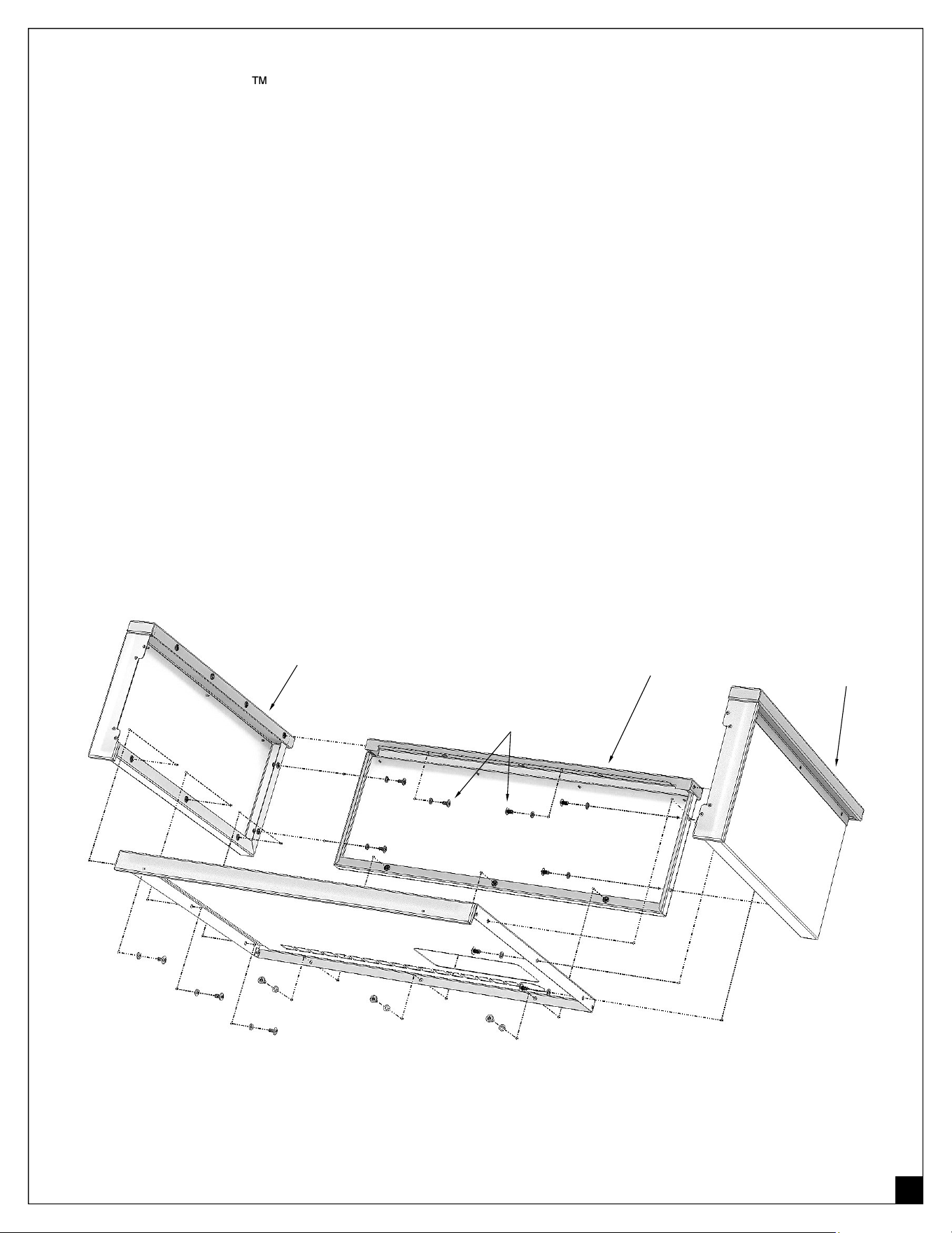
STEP 1:
Assemble your Artisan insulated jacket by attaching the LEFT PANEL to the BOTTOM PANEL with
3 screws and 3 lock washers in the lower section of the left panel.
TIP: Do not tighten the screws at this time. Leave them loose for easier assembly
and fasten all screws as a final step.
STEP 2:
Continue by attaching the RIGHT PANEL to the BOTTOM PANEL as indicated on step 1.
STEP 3:
Assemble the BACK PANEL and attach it to the BOTTOM PANEL with 3 screws and 3 lock washers.
You can now attach the BACK PANEL to the SIDE PANELS (left and right) with 2 screws and 2 washers
in the center section.
There are 2 more additional screws and lock washers to install in the upper section (CAP) of the back
panel. Install the CAP screws and washers.
Align the SIDE PANEL CAPS with the BACK PANEL CAP and tighten the top CAP screws first.
STEP 4:
Tighten up all the screws in the assembly while making sure all front faces are flush to each other.
(See figure # 1)
LEFT
PANEL
RIGHT
PANEL
BOTTOM PANEL
REAR PANEL
REAR PANEL CAP
LEFT CAP
RIGHT CAP
CAP SCREWS
Figure # 1
4
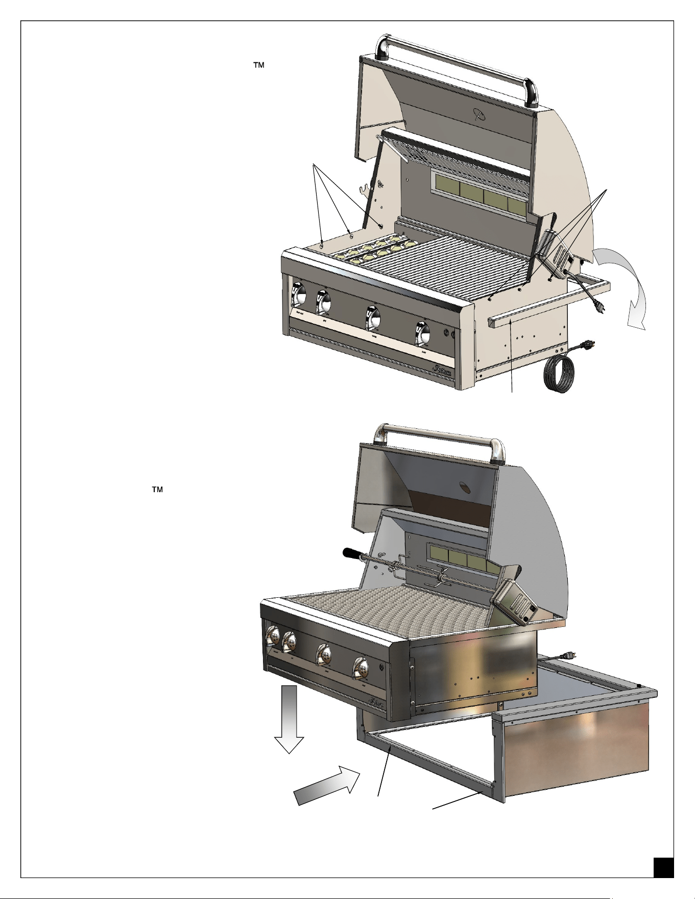
STEP 5:
Prepare to install your Artisan
BBQ into the insulated jacket assem-
bly by removing the countertop sup-
port ring attached to the firebox of the
BBQ.
Access these screws by removing the
grill cooking grates and setting them
aside.
The countertop support ring is at-
tached with 3 screws on each side of
the firebox.
(See Figure # 2)
Save these 6 screws as they will be
needed later.
STEP 6:
Insert the Artisan BBQ inside
the insulated jacket by sliding it
over the support rails located on
the BOTTOM PANEL.
(See Figure # 3)
Secure the BBQ firebox to the in-
sulated jacket by re-installing the
6 screws saved from the counter-
top support ring as shown on the
previous step above.
SUPPORT RAILS
Figure # 3
Figure # 2
3 SCREWS
3 SCREWS
REMOVE
SUPPORT RING
5
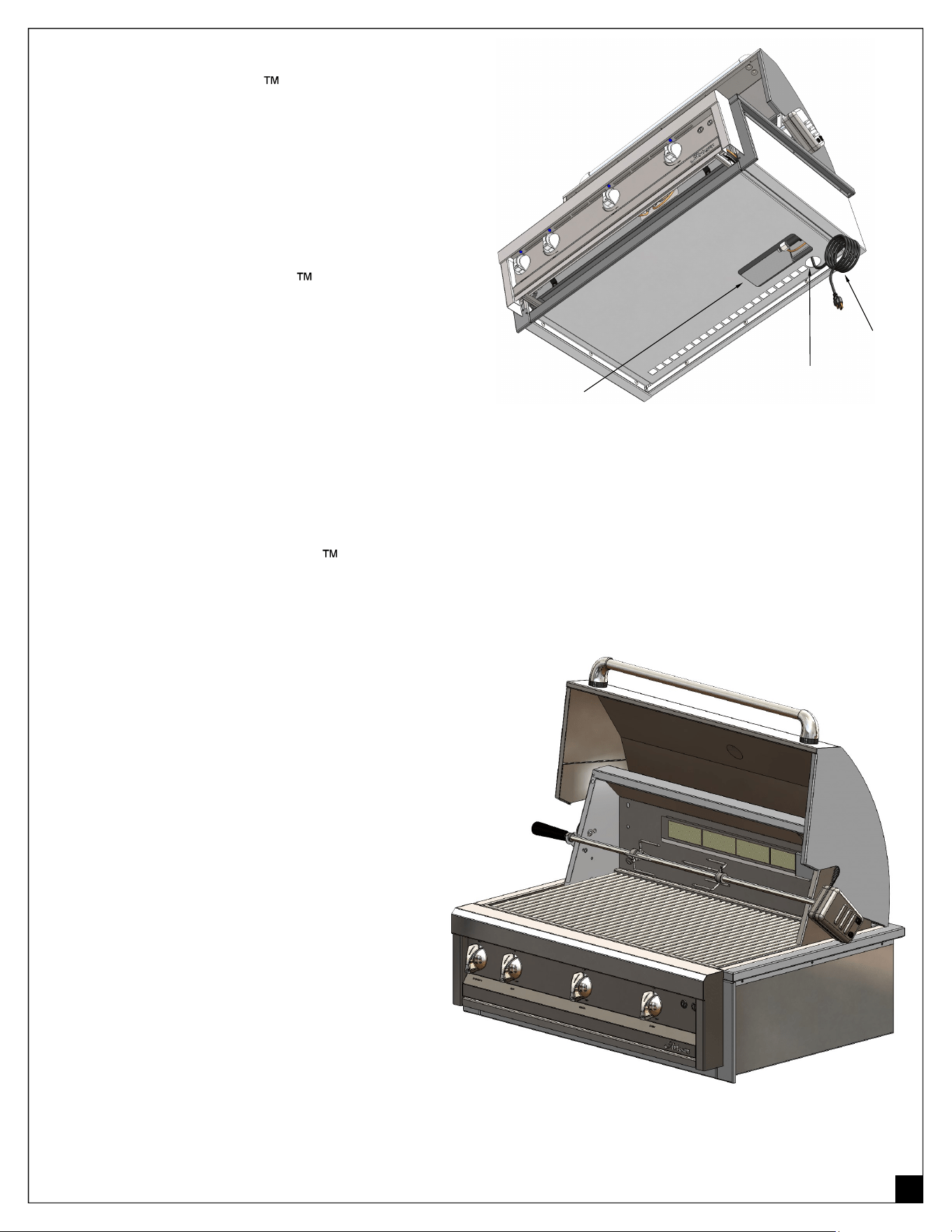
STEP 7:
On 32” and 36” Artisan BBQ units there is a
power cable that is required for the standard light.
The cable can be fed through the round hole that
is directly below the BBQ electrical box.
The large rectangular cutout opening is meant for
the fuel connection (NG or LP Fuel).
NOTE: Refer to the Artisan BBQ manual for
the proper fuel connections.
STEP 8:
You can now install the Artisan BBQ with the insulated jacket in your countertop and secure it with
a bead of clear silicone around the top perimeter.
NOTE: Alternatively, you can install the insulat-
ed jacket by itself onto the countertop as a first
step and then install the BBQ into the insulated
jacket for final assembly.
Figure # 4
POWER
CABLE
POWER
CABLE HOLE
FUEL SUPPLY
ACCESS
OPENING

6
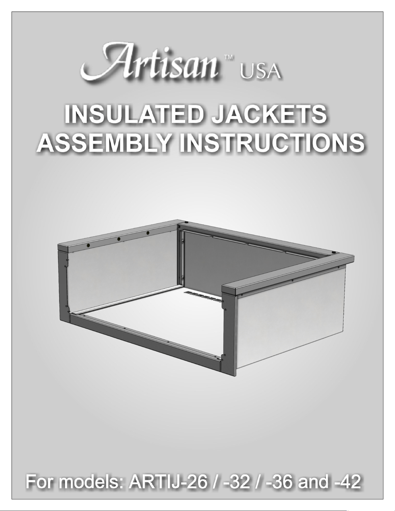
Artisan Insulated Jacket
Assembly Instructions
Artisan USA Grills
All Rights Reserved • 06/2023