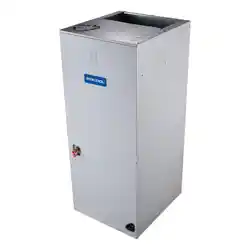
MRCOOL
®
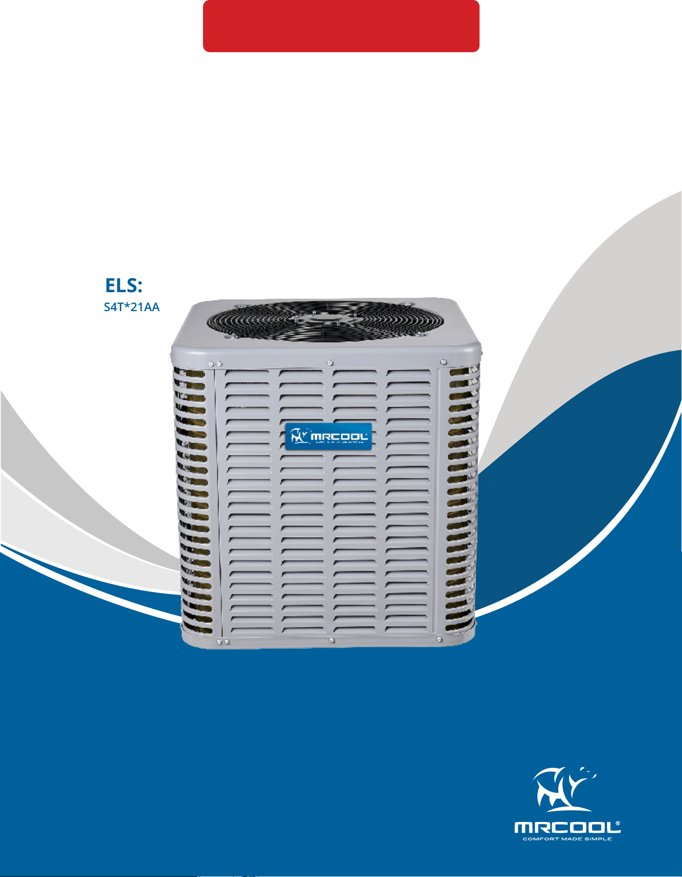
Signature Series
Split System Heat Pump
INSTALLATION & OWNER’S MANUAL
Read this manual carefully before installation and keep it where
the operator can easily nd it for future reference.
Due to updates and constantly improving performance, the
information and instructions within this manual are subject to
change without notice.
Version Date: August 26, 2025
Please visit www.mrcool.com/documentation
to ensure you have the latest version of this manual.
This product utilizes R-454B refrigerant
MODELS:
MCAESAS4T*21AA

mrcool.com1
CONTENTS
SAFETY ................................................................................................................... 2
UNIT OVERVIEW .................................................................................................... 9
2.1 Nomenclature .......................................................................................... 9
2.2 Unit Size .................................................................................................... 9
2.3 Refrigerant Pipeline Restriction ........................................................... 10
2.4 Heating Valve Core Information .......................................................... 10
2.5 Positioning Restriction .......................................................................... 11
2.6 Refrigerant Charge & Room Area Limitations .................................... 13
INDOOR UNIT INSTALLATION ........................................................................... 17
3.1 Installation Preparation ........................................................................ 17
3.2 Refrigerant Line Precautions ................................................................ 17
3.3 Refrigerant Pipeline Routing ................................................................ 18
3.4 Refrigerant Line Connection ................................................................. 19
3.5 Refrigerant Pipeline Brazing ................................................................. 20
3.6 Leakage Check ........................................................................................ 21
3.7 Emptying Pipeline & Coil ....................................................................... 21
3.8 Open the Service Valve .......................................................................... 22
3.9 Low Voltage Electrical Connections ..................................................... 22
3.10 High Voltage Electrical Connections .................................................. 24
3.11 System Startup ..................................................................................... 24
3.12 System Refrigerant Charging Regulation .......................................... 25
POST-INSTALLATION .......................................................................................... 26
4.1 System Operation .................................................................................. 26
4.2 Troubleshooting of Fault Codes ........................................................... 28
4.3 Operation Limits .................................................................................... 30
4.4 Wiring Diagram ...................................................................................... 31
4.5 Cleaning Precautions ............................................................................. 32
4.6 Pre-Season Inspection & Maintenance ............................................... 32
1
Contents
2
3
4
mrcool.com 2 2
Incorrect usage may cause serious damage or injury.
The symbols below are used throughout this manual to indicate instructions that should be
followed closely or actions that should be avoided to prevent death, injury, and/or property
damage.
Safety Precautions
CAUTION
Indicates the possibility of personal injury or loss of life.
Indicates the possibility of property damage or serious
consequences.
Read Before Using
WARNING
WARNING FOR PRODUCT INSTALLATION
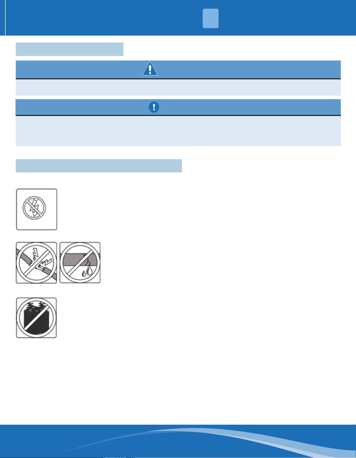
1. The appliance should be installed in accordance with national wiring regulations.
2. This information is intended for use by individuals with sucient electrical and mechanical experience.
Attempting to repair central air conditioning products may result in personal injury and/or property
damage.
3. An indoor unit is required and is to be equipped with a piston or TXV. The model of piston or TXV is
selected by the manufacturer and is not designed to be changed by yourself.
4. When opening the liquid pipeline service valve, be extra careful. Turn the valve stem counterclockwise until
the valve stem touches the bead. Failure to observe this warning will result in sudden discharge, which may
result in personal injury and/or property damage.
5. Brazing is required. Failure to check the wiring or use the correct maintenance tools may result in
equipment damage or personal injury. If using existing refrigerant lines, make sure that all joints are
brazed, not soldered.
6. The unit should be stored in a well-ventilated room without continuously operating ames or other
potential ignition.
7. Disconnect all remote electric power supplies before servicing. Failure to do so increases the risk of electric
shock, injury, or death.
8. The unit utilizes ammable refrigerant with a risk of re. Do not puncture the refrigerant tubing. Repairs
should only be completed by trained service personnel.
9. Disposal should be in accordance with federal or local regulations.
10. Consult all included documentation before attempting to service this product. All safety precautions must
be followed.
11. Do not install auxiliary devices which may be ignition sources in the ductwork, other than auxiliary devices
listed for use with the specic appliance.
SAFETY
1
ELECTRICAL WARNINGS
1. Failure to observe these warnings may result in property damage, serious personal injury, or death.
2. Disconnect all power before maintenance, including remote disconnection. Follow proper locking/tagging
procedures to ensure that the power supply will not be accidentally energized.
3. Grounding is required. Failure to check or use the correct maintenance tools may result in equipment
damage or personal injury. Reconnect all grounding devices. All parts of this product that can conduct
current are grounded. If the grounding wire, screw, strap, clip, nut, or washer used to complete the
grounding path is removed during maintenance, it must be put back in place and properly xed.
4. High current leakage is a possibility if grounding is not completed before connecting the power supply.
Failure to observe this warning may result in property damage, serious personal injury, or death.
mrcool.com3
WARNING FOR PRODUCT USE
1. This unit is not intended for use by persons (including children) with reduced physical, sensory, or mental
capabilities, or lack of experience and knowledge, unless they have been given supervision or instruction
concerning use of the appliance by a person responsible for their safety.
2. Do not touch the top of the compressor. The hot surface may cause mild to severe burns. Failure to
observe this caution may result in property damage or personal injury.
3. This product may expose you to chemicals including lead and lead components, which are known to cause
cancer, birth defects, or other reproductive harm in California. For more information, please visit www.
P65Warnings.ca.gov
4. Children should be supervised to ensure that they do not play with the appliance.
CAUTION
1. In order to avoid electric shock, make sure that the unit is grounded and that the ground wire is not
connected to a gas or water pipe, lightning conductor, or telephone ground wire.
2. Do not operate the air conditioner with wet hands. An electric shock may happen.
3. Do not operate the air conditioner when using a room fumigation-type insecticide. Failure to observe this
precaution could cause the chemicals to become deposited in the unit, which could endanger the health of
those who are hypersensitive to chemicals. It may also cause the refrigerant sensor to alarm.
4. To avoid oxygen deciency, ventilate the room suciently if equipment with a burner is used together with
the air conditioner.
5. Arrange the drain hose to ensure smooth drainage. Incomplete drainage may cause damage to the
building, furniture, etc.
6. Never touch the internal parts of the controller. Do not remove the front panel. Some parts inside are
dangerous to touch, and machine troubles could occur.
7. Attention is drawn to the fact that additional transportation regulations may exist with respect to
equipment containing ammable gas. The maximum number of pieces of equipment or the conguration
of the equipment permitted to be transported together will be determined by the applicable transport
regulations.
8. Signs for similar appliances used in a work area are generally addressed by local regulations and give the
minimum requirements for the provision of safety and/or health signs for a work location.
9. Storage package protection should be constructed in such a way that mechanical damage to the equipment
inside the package will not cause a refrigerant leak.
10. The maximum number of pieces of equipment permitted to be stored together will be determined by local
regulations.
11. All required signs are to be maintained and employers should ensure that employees receive suitable and
sucient instruction and training on the meaning of appropriate safety signs and the actions that need to
be taken in connection with these signs.
12. The eectiveness of signs should not be diminished by too many signs being placed together.
13. Any pictograms used should be as simple as possible to contain only essential details.
14. The storage of the appliance should be in accordance with the applicable regulations or instructions,
whichever is more stringent.
15. Do not place appliances which produce open ame in places exposed to the air ow from the unit or under
the indoor unit. It may cause incomplete combustion or deformation of the unit due to the heat.
16. Do not install the unit in a location where ammable gas may leak out. If the gas leaks out and stays
around the unit, a re may break out.
SAFETY
1

mrcool.com 4
4
• This unit uses R-454B refrigerant, which has a safety level of A2L. Attempting to repair central air-
conditioning products may result in property damage, serious personal injury, or death. Use only the service
equipment approved for use with R-454B. The refrigerant cylinder is painted "ashen" to indicate the type of
refrigerant, and may contain a "dip" tube to allow liquid refrigerant to be lled into the system. All R-454B
systems use POE oil, which can easily absorb moisture from the atmosphere. In order to limit this "moisture
absorption" eect, the system should be sealed as much as possible. If the system is exposed to the
atmosphere for more than 4 hours, the compressor oil must be changed. Do not destroy the vacuum with
air, and always replace the dryer when you open the system for component replacement.
• Before opening the system, recover the refrigerant to release the pressure. Failure to follow the correct
procedures will lead to personal illness or injury or serious equipment damage.
• Do not use means to accelerate the defrosting process or to clean, other than those recommended by
MRCOOL
®
.
• The unit should be stored in a room that does not have continuously operating ignition sources (for
example: open ames, an operating gas appliance, or an operating electric heater)
• Do not pierce/puncture refrigerant lines or burn the unit.
• Be aware that refrigerants may not contain an odor.
• Any person who is involved with working on or opening a refrigerant circuit should hold a current valid
certicate from an industry-accredited assessment authority, which authorizes their competence to handle
refrigerants safely in accordance with an industry-recognized assessment credential.
• Servicing should only be performed as recommended by MRCOOL
®
.
• Maintenance and repair requiring the assistance of other skilled personnel shall be carried out under the
supervision of a person competent in the use of ammable refrigerants.
• Prior to beginning work on systems containing ammable refrigerants, safety checks are necessary to
minimize the risk of ignition.
• When repairing the refrigerating system, comply with the following precautions prior to conducting work on
the system:
• Work should be undertaken according to controlled procedures so as to minimize the risk of the
presence of ammable gases or vapors while the work is being performed.
• All maintenance sta and others working in the local area should be instructed on the nature of work
being carried out. Work in conned spaces should be avoided.
• The area should be checked with an appropriate refrigerant detector prior to and during work, to
ensure the technician is aware of a potentially toxic or ammable environment.
• Ensure that the leak detection equipment being used is suitable for use with all applicable refrigerants, i.e.
non-sparking, adequately sealed or intrinsically safe.
• If any brazing/welding is to be conducted on the refrigerating equipment or any associated parts,
appropriate re extinguishing equipment should be available and easily accessible. Have a dry powder
or CO2 re extinguisher adjacent to the charging area.
• When carrying out work in relation to a refrigerating system that involves exposing any pipe work, no
sources of ignition should be used in such a manner that it may lead to the risk of re or explosion.
• All possible ignition sources, including cigarette smoking, should be kept suciently far away from the site of
installation, repair, removal, and disposal of the unit, during which refrigerant can possibly be released into
the surrounding space. Prior to beginning work, the area around the equipment is to be surveyed to make
sure that there are no ammable hazards or ignition risks. "No Smoking" signs should be clearly displayed.
• Ensure that the area is in the open or that it is adequately ventilated before opening the system or
conducting any hot work. A degree of ventilation should continue during the period that the work is carried
out. The ventilation should safely disperse any released refrigerant and preferably expel it externally into the
surroundings.
• Where electrical components are being changed, they should be t according to their purpose and to the
correct specication. At all times the MRCOOL
®
's maintenance and service guidelines should be followed. If
in doubt, consult MRCOOL
®
's technical department for assistance. The following checks should be applied to
installations using ammable refrigerants:
• The actual refrigerant charge is in accordance with the room size within which the refrigerant-containing
parts are installed.
FLAMMABLE REFRIGERANT WARNINGS
SAFETY
1
mrcool.com5
FLAMMABLE REFRIGERANT WARNINGS
• The ventilation machinery and outlets are operating adequately and are not obstructed.
• If an indirect refrigerating circuit is being used, the secondary circuit should be checked for the
presence of refrigerant.
• Equipment marking must remain visible and legible. Markings and signs that are illegible should be
corrected.
• Refrigerating pipe or components are installed in a position where they are unlikely to be exposed to
any substances which may corrode refrigerant-containing components, unless the components are
constructed of materials that are inherently resistant to corrosion or are suitably protected against
corrosion.
• Repair and maintenance of electrical components should include initial safety checks and component
inspection procedures. If a fault exists that could compromise safety, then no electrical supply should be
connected to the circuit until the fault has been dealt with satisfactorily.
• If the fault cannot be corrected immediately but it is necessary to continue operation, an adequate
temporary solution should be used. This should be reported to the owner of the equipment so that all
parties are advised. Initial safety checks should include:
• That capacitors are discharged; this should be done in a safe manner to avoid the possibility of
sparking.
• That no live electrical components and wiring are exposed while charging, recovering, or purging the
system.
• That there is continuity of proper grounding.
• Sealed electrical components should be replaced.
• Intrinsically safe components must be replaced.
• Check that cabling will not be subject to wear, corrosion, excessive pressure, vibration, sharp edges, or
any other adverse environmental eects. The check should also take into account the eects of aging or
continual vibration from sources such as compressors or fans.
• Under no circumstances should potential sources of ignition be used while searching for or in detection of
refrigerant leaks. A halide torch (or any other detector using a naked ame) should not be used.
• Electronic leak detectors may be used to detect refrigerant leaks but, in the case of ammable refrigerants,
the sensitivity may not be adequate, or may need recalibration. (Detection equipment should be calibrated
in a refrigerant-free area.) Ensure that the detector is not a potential source of ignition and is suitable for
the refrigerant used. Leak detection equipment should be set at a percentage of the LFL of the refrigerant
and should be calibrated for the refrigerant employed, and the appropriate percentage of gas (25%
minimum) is conrmed.
• If a leak is suspected, all naked amed should be removed/extinguished.
• If a leakage of refrigerant which requires brazing is found, all of the refrigerant should be recovered from
the system, or isolated (by means of shut-o valves) in a part of the system remote from the leak.
• Leak detection uids are also suitable for use with most refrigerants but the use of detergents containing
chlorine should be avoided as the chlorine may react with the refrigerant and corrode the copper pipe-
work. Examples of leak detection uids include the bubble method.
• When breaking into the refrigerant circuit to make repairs or for any other purpose, conventional
procedures should be used. However, for ammable refrigerants it is important that best practices be
followed, since ammability is a consideration. The following procedure should be adhered to:
• safely remove refrigerant following local and national regulations
• evacuate
• purge the circuit with inert gas
• evacuate
• continuously ush or purge with inert gas when using ame to open circuit
• open the circuit
• The refrigerant charge should be recovered into the correct recovery cylinders if venting is not allowed by
local and national codes. For appliances containing ammable refrigerants, the system should be purged
with oxygen-free nitrogen to render the appliance safe for ammable refrigerants. This process might
need to be repeated several times. Compressed air or oxygen should not be used for purging refrigerant
systems.
SAFETY
1

mrcool.com 6
6
FLAMMABLE REFRIGERANT WARNINGS
• For appliances containing ammable refrigerants, refrigerant purging should be achieved by breaking
the vacuum in the system with oxygen-free nitrogen and continuing to ll until the working pressure
is achieved, then venting to atmosphere, and nally pulling down to a vacuum. This process should be
repeated until no refrigerant is within the system. When the nal oxygen-free nitrogen charge is used, the
system should be vented down to atmospheric pressure to enable work to take place.
• The outlet for the vacuum pump should not be close to any potential ignition sources, and ventilation
should be available.
• Ensure that contamination of dierent refrigerants does not occur when using charging equipment. Hoses
or lines should be as short as possible to minimize the amount of refrigerant they contain.
• When using a refrigerant tank with a siphon to add refrigerant, the tank should be placed upright. When
using a refrigerant tank without a siphon to add refrigerant, the refrigerant tank should be placed upside
down. Ensure that the refrigeration system is grounded prior to charging the system with refrigerant.
• In general, R-454B refrigerant doesn't have a siphon tube or dip tube into the tank. For this situation, they
must be charged in liquid form to prevent fractionation of the blended refrigerant and that requires the jug
to be inverted during charging.
• Label the system when charging is complete (if it is not already labeled).
• Take extreme care not to overll the refrigeration system.
• Prior to recharging the system, it should be pressure-tested with the appropriate purging gas. The system
should be leak-tested on completion of charging but prior to commissioning. A follow-up leak test should
be carried out prior to leaving the site.
• Before carrying out this procedure, it is essential that the technician is completely familiar with the
equipment and all its detail. It is recommended that all refrigerants are recovered safely. Prior to the task
being carried out, an oil and refrigerant sample should be taken in case analysis is required prior to re-use
of reclaimed refrigerant. Is is essential that electrical power is available before the task is commenced.
• Become familiar with the equipment and its operation
• Isolate system electrically
• Before attempting the procedure ensure that:
• mechanical handling equipment is available
• all personal protective equipment is available and being used correctly
• the recovery process is supervised at all times by a competent person
• recovery equipment and cylinders conform to the appropriate standards
• Pump down refrigerant system, if possible.
• If a vacuum is not possible, make a manifold so that refrigerant can be removed from various parts of
the system.
• Make sure that the cylinder is situated on the scales before recovery takes place
• Start the recovery machine and operate it in accordance with the manufacturer's instructions.
• Do no overll cylinders. (No more than 80% volume liquid charge).
• Do not exceed the maximum working pressure of the cylinder, even temporarily.
• When the cylinders have been lled correctly and the process have been completed, make sure that the
cylinders and the equipment are closed o.
• Recovered refrigerant should not be charged into another refrigeration system unless it has been
cleaned and checked.
• Equipment should be labeled stating that it has been decommissioned and emptied of refrigerant. The
label should be dated and signed. Ensure that there are labels on the equipment stating the equipment
contains ammable refrigerant.
• When removing refrigerant from a system, either for servicing or decommissioning, it is recommended
that all refrigerants are removed safely.
• When transferring refrigerant into cylinders, ensure that only appropriate refrigerant recovery cylinders
are employed. Ensure that the correct number of cylinders for holding the total system charge is available.
All cylinders to be used are designated for the recovered refrigerant and labeled for that refrigerant (i.e.
special cylinders for the recover of refrigerant). Cylinders should be complete with a pressure-relief valve
and associated shut-o valves in good working order. Empty recovery cylinders are evacuated and, if
possible, cooled before recovery occurs.
SAFETY
1
mrcool.com7
FLAMMABLE REFRIGERANT WARNINGS
• The recovery equipment should be in good working order with a set of instructions concerning the
equipment and should be suitable for the recovery of the ammable refrigerant. If in doubt, MRCOOL
®
should be consulted. In addition, a set of calibrated weighing scales should be available and in good
working order. Hoses should be complete with leak-free couplings and in good condition.
• The recovered refrigerant should be processed according to local legislation in the correct recovery
cylinder, and the relevant waste transfer note arranged. Do not mix refrigerants in recovery units, and
especially not in cylinders.
• If compressors or compressor oils are to the removed, ensure that they have been evacuated to an
acceptable level to make certain that ammable refrigerant does not remain within the lubricant. The
compressor body should not be heated by an open ame or other ignition sources to accelerate this
process. When oil is drained from a system, it should be carried out safely.
• Do not use the air conditioner for other purposes.
• In order to avoid air quality deterioration, do not use the unit for the cooling of precision instruments,
food, plants, animals or works of art.
• Before cleaning, be sure to stop the operation, turn the breaker o, or unplug the supply cord. Otherwise,
electric shock and injury may occur.
• In order to avoid electric shock or re, make sure that an earth ground detector is installed.
• Never touch the air outlet or the horizontal blades while the swing ap is in operation. Your ngers may
become caught or the unit may break down.
• Never put any objects into the air inlet or outlet.
• Objects touching the fan at high speed can be dangerous.
• Never inspect or service the unit by yourself.
• Ask a qualied service person to perform this task.
• Do not dispose of electrical appliances as unsorted municipal waste. This waste should be collected
separately for special treatment. Contact your local government for information regarding the connection
systems available.
• If electrical appliances are disposed of in landlls or dumps, hazardous substances can leak into the
groundwater and get into the food chain, harming your health and well-being.
• To prevent refrigerant leaks, contact your dealer.
• When the system is installed and operates in a small room, it is required to maintain the concentration
of the refrigerant below the limit, in case a leak occurs. Otherwise, oxygen in the room may be aected,
resulting in a serious accident.
• The refrigerant in the unit is safe and normally does not leak.
• If the refrigerant leaks into the room and comes into contact with the re of a burner, a heater or a cooker,
a harmful gas could be released.
• Turn o any combustible heating devices, ventilate the room, and contact the dealer where you purchased
the unit.
• Do not use the unit until a service person conrms that the refrigerant leak is repaired.
• Keep any required ventilation openings clear of obstruction.
• That pipe-work including piping material, pipe routing, and installation should include protection from
physical damage in operation and service, and be in compliance with national and local codes and
standards.
• That after completion of eld piping for split systems, the eld pipework should be pressure-tested with an
inert gas and then vacuum tested prior to refrigerant charging, according to the following requirements.
• The minimum test pressure for the low side of the system should be the low side design pressure, and the
minimum test pressure for the high side of the system shall be the high side design pressure, unless the
high side of the system cannot be isolated from the low side of the system, in which case the entire system
should be pressure tested for the low design pressure.
• Ducts connected to an appliance should not contain a potential ignition source.
• Precautions should be taken to avoid excessive vibration or pulsation to refrigeration piping.
• The protection devices, piping, and ttings should be protected as far as possible against adverse
environmental eects, for example the danger of water collecting and freezing in relief pipes or the
accumulation of dirt and debris.
SAFETY
1
mrcool.com 8
8
FLAMMABLE REFRIGERANT WARNINGS
• Piping in refrigerating systems should be so designed and installed as to minimize the likelihood of
hydraulic shock damaging the system.
• The solenoid valves should be correctly positioned in the piping to avoid hydraulic shock and should not
block in liquid refrigerant unless adequate relief is provided.
• Steel pipes and components should be protected against corrosion with a rustproof coating before
applying any insulation.
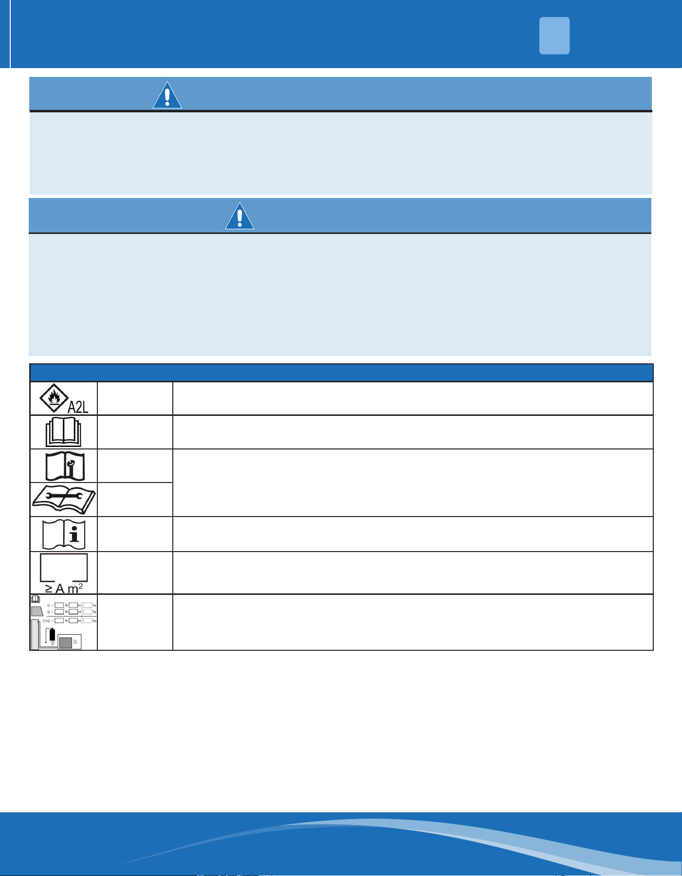
Symbols Displayed on Indoor & Outdoor Unit
DANGER
This symbol shows that this appliance uses a ammable refrigerant. If the refrigerant
is leaked and exposed to an external ignition source, there is a risk of re.
CAUTION This symbol shows that the operation manual should be read carefully.
CAUTION
This symbol shows that a service personnel should be handling this equipment with
reference to the installation manual.
CAUTION
CAUTION
This symbol shows that information is available such as the operating manual or
installation manual.
CAUTION
This symbol shows that when MRCOOL
®
requires additional charge, record the
resulting total refrigerant charge for each refrigerating system.
WARNING
This symbol shows that the appliance should be installed, operated, and stored in a
room with a oor area not less than the minimum room area.
SAFETY
1
• The outdoor unit must be combined with an indoor unit with a refrigerant leak detection device.
• These instructions are exclusively intended for qualied contractors or authorized installers.
• Work on the refrigerant circuit with mild ammable refrigerant in safety group A2L may only be carried
out by authorized heating contractors. These heating contractors must be trained in accordance with UL
60335-2-40, Section HH. The certicate of competence from an industry-accredited body is required.
• Work on electrical equipment may only be carried out by a qualied electrician.
• Before initial commissioning, all safety-related points must be checked by the particular certied heating
contractors. The system must be commissioned by the system installer or a qualied person authorized by
the installer.
GENERAL WARNINGS
mrcool.com9
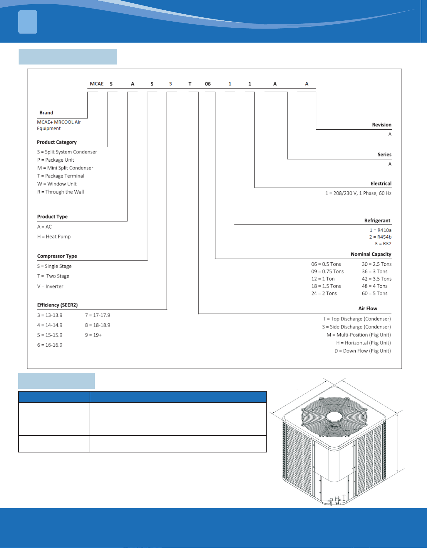
2.1 Nomenclature
UNIT OVERVIEW
2
2.2 Unit Size
MCAE = MRCOOL Air
Equipment
MCAE
Unit Size H x W x L in (cm)
18K / 24K / 30K 25 x 23.6 x 23.6 (63.5 x 58.42 x 58.42)
36K 25 x 29.14 x 29.14 (63.5 x 73.66 x 73.66)
42K / 48K / 60K 32.88 x 29.14 x 29.14 (81.28 x 73.66 x 73.66)
The weight of the unit is attached to the carton.
When installing the outdoor unit on the roof, make sure that the roof
can support the weight of the outdoor unit. It is recommended to
choose appropriate isolation to prevent sound or vibration from being
transmitted to the building structure.
L
W
H
mrcool.com 10
10
UNIT OVERVIEW
2
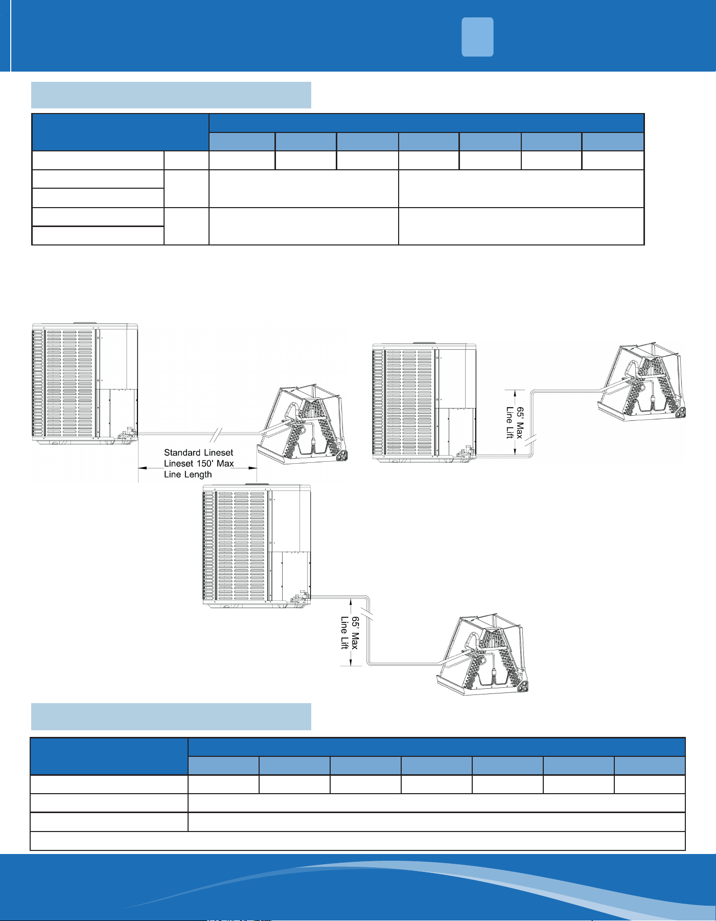
2.3 Refrigerant Pipeline Restriction
Refrigerant Piping
Capacity (Kbtu/h)
18K 24K 30K 36K 42K 48K 60K
Liquid-Gas In 3/8-3/4 3/8-3/4 3/8-3/4 3/8-3/4 3/8-3/4 3/8-7/8 3/8-7/8
Max Refrigerant
Ft (M) 100 (30.48) 150 (45.72)
Line Length
Max Elevation
Ft (M) 32 (9.76) 65 (19.81)
Vertical Lift**
* It is recommended to adopt standard pipeline size; See the Refrigerant Charge section of this manual.
• Maximum equivalent length of pipeline = 150 feet / 45.72 meters
• Maximum vertical equivalent length = 65 feet / 19.81 meters
• Use only the pipe diameters shown in the table.
• If the suction line exceeds 65 feet (19.81 meters), do not use a larger suction line than recommended.
2.4 Heating Valve Core Information
Valve Core Information
Capacity (Kbtu/h)
18K 24K 30K 36K 42K 48K 60K
Valve Core Model 038 040 048 048 052 060 066
Valve Core Type One-Way Throttle Valve
Connection Method Brazing
Note: Orice Size (In) = Valve Core Model/100
mrcool.com11
UNIT OVERVIEW
2
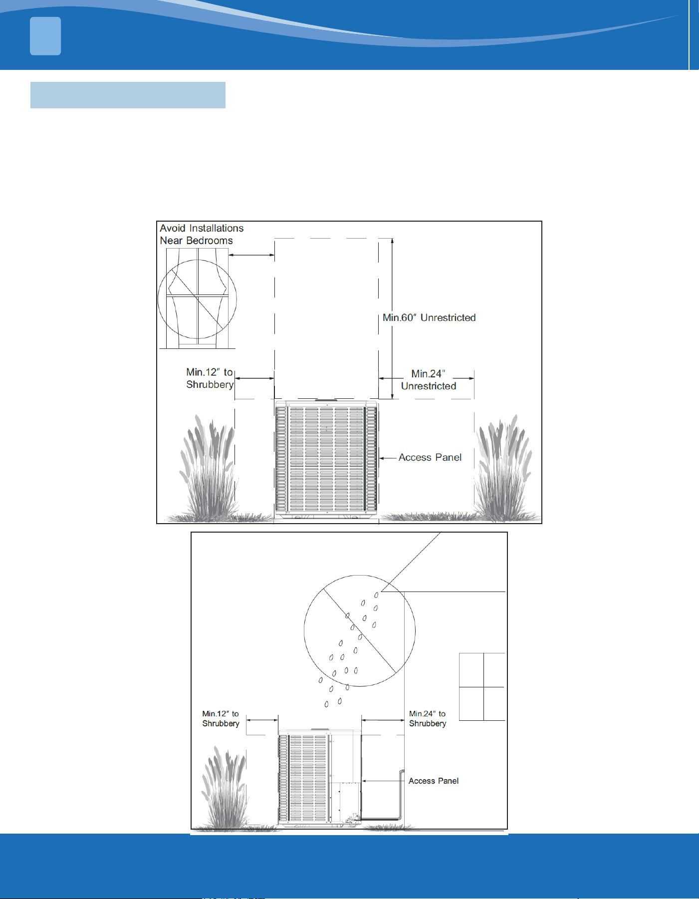
2.5 Position Restriction
• Ensure the discharge area (at least 60 inches above the top of the unit) is unrestricted.
• Don't put the outdoor unit near a bedroom, as the normal operating sound may be oensive.
• Position the unit, leaving enough space for smooth airow, wiring, refrigerant lines, and maintainability.
• 12 inches minimum is allowed. The clearance from one side of the access panel to the wall should be at least
24 inches, next to the control panel near the access panel.
• Keep a distance of 24 inches between adjacent units.
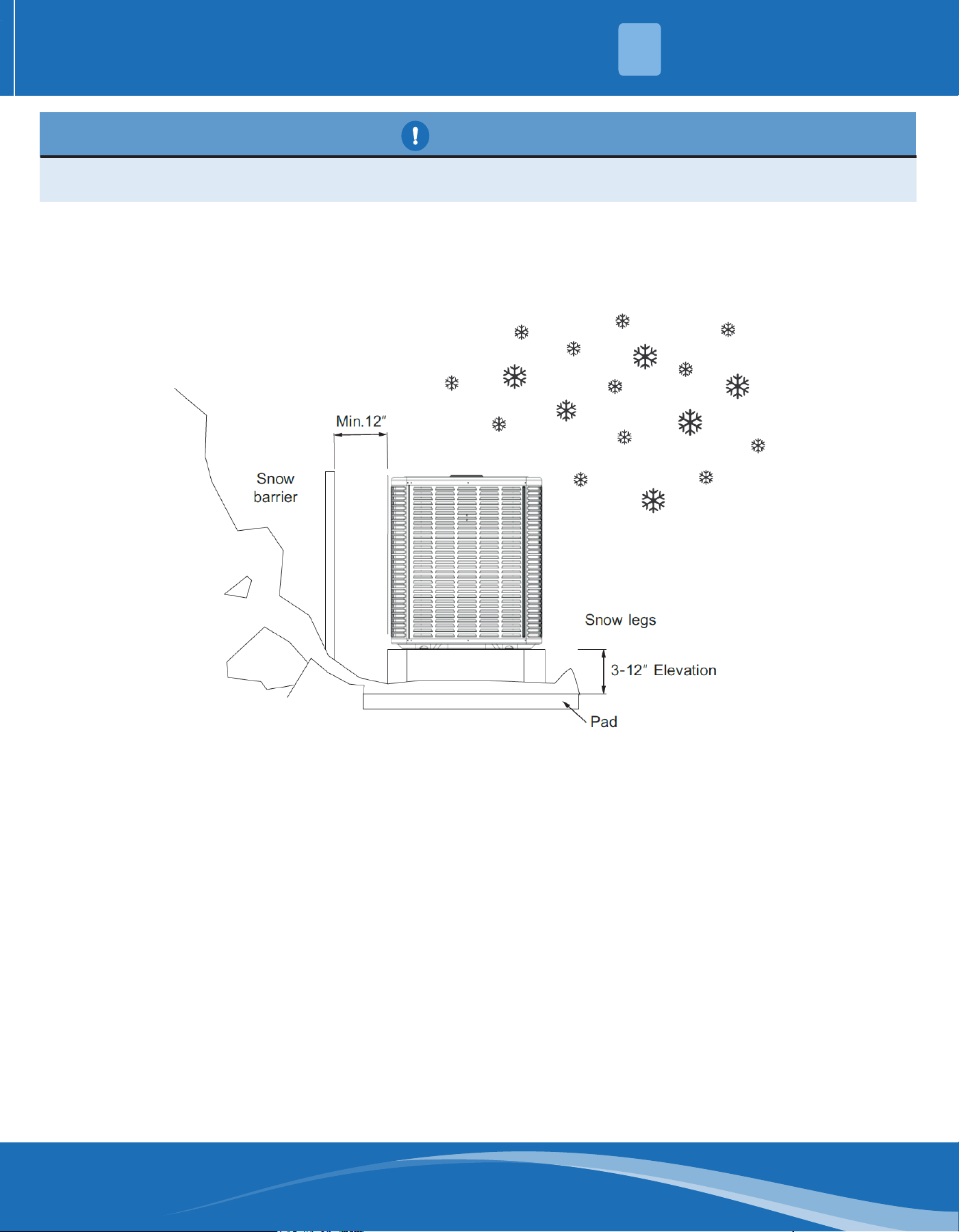
• Place the unit in a place where water, snow, or ice cannot fall directly on the device from the roof or
overhangs.
mrcool.com 12
12
UNIT OVERVIEW
2
• Depending on the local weather conditions, the unit should be raised by 3-12 inches. This extra height will
allow the snow and ice melted during the defrosting cycle to be discharged before re-freezing. Make sure
that the drain hole on the unit chassis is not blocked, otherwise it will hinder the defrosting water discharge.
• If possible, avoid places that are prone to snow. If this is not feasible, a snow barrier should be installed
around the unit to prevent snow accumulation on the side of the unit.
CAUTION
Precautions must be taken for units installed in areas with snow and long-term temperatures below the
freezing point.
Corrosive Environment
Exposure to corrosive environments may shorten the service life of the unit, corrode metal parts, and/or
negatively aect the performance of the unit. Corrosive elements include but are not limited to: sodium chloride,
sodium hydroxide, sodium sulfate, and other compounds commonly found in seawater, sulfur, chlorine, uorine,
fertilizers, and various chemical pollutants from industrial/manufacturing plants. If it is installed in an area that
may be exposed to corrosive environments, special attention should be paid to the placement and maintenance
of the unit.
• Lawn sprinklers/hoses/waste water should not be sprayed directly on the outer panel of the unit for a long
time.
• In coastal areas, install the unit on the side away from the waterfront.
• Fences or shrubs can provide some shielding protection for the unit, but the minimum device clearance must
still be kept.
• Clean the outdoor coil and any exposed external services about every three months.
mrcool.com13
2.6 Refrigerant Charge & Room Area Limitations
UNIT OVERVIEW
2
• In UL/CSA 60335-2-40, R454B
refrigerant is classied as class A2L,
which is mildly ammable. Therefore,
R454B refrigerant will limit the area of
the rooms being served by the system.
• Similarly, the total amount of
refrigerant in the system should be
less than or equal to the allowable
maximum refrigerant charge. The
allowable maximum refrigerant charge
depends on the area of the rooms
being served by the system.
NOTE:
The abbreviations in this section are explained as follows:
Mc - the actual refrigerant charge in the system
A - the actual room area where the appliance is installed
Amin - the required minimum room area
Mmax - the allowable maximum refrigerant charge in a room
Qmin - the minimum circulation airow
Anvmin - the minimum opening area for connected rooms
TAmin - the required minimum total area of the conditioned
space (for units serving two or more rooms with an air duct
system)
TA - the total area of the conditioned space connected by air
ducts (for units serving two or more rooms with an air duct
system)
CAUTION
The space considered should be any space which contains refrigerant-containing parts or into which
refrigerant could be released. The room area (A) of the smallest, enclosed, occupied space should be used in
the determination of the refrigerant quantity limits.
Room Area Calculation Requirements
• For determination of room area (A), when used to calculate the refrigerant charge limit, the following shall
apply:
• The room area (A) shall be dened as the room area enclosed by the projection to the base of the walls,
partitions, and doors of the space in which the appliance is installed. Spaced connected by only drop
ceilings, ductwork, or similar connections should not be considered a single space.
• Units mounted higher than 70.86 in (1.79m) and spaces divided by partition walls that are no higher than
62.98 in (1.59m) shall be considered a single space.
• Rooms on the same oor and connected by an open passageway between the spaces can be considered a
single room when determining compliance to Amin, if the passageway complies with all of the following.
1. It is a permanent opening.
2. It extends to the oor.
3. It is intended for people to walk through.
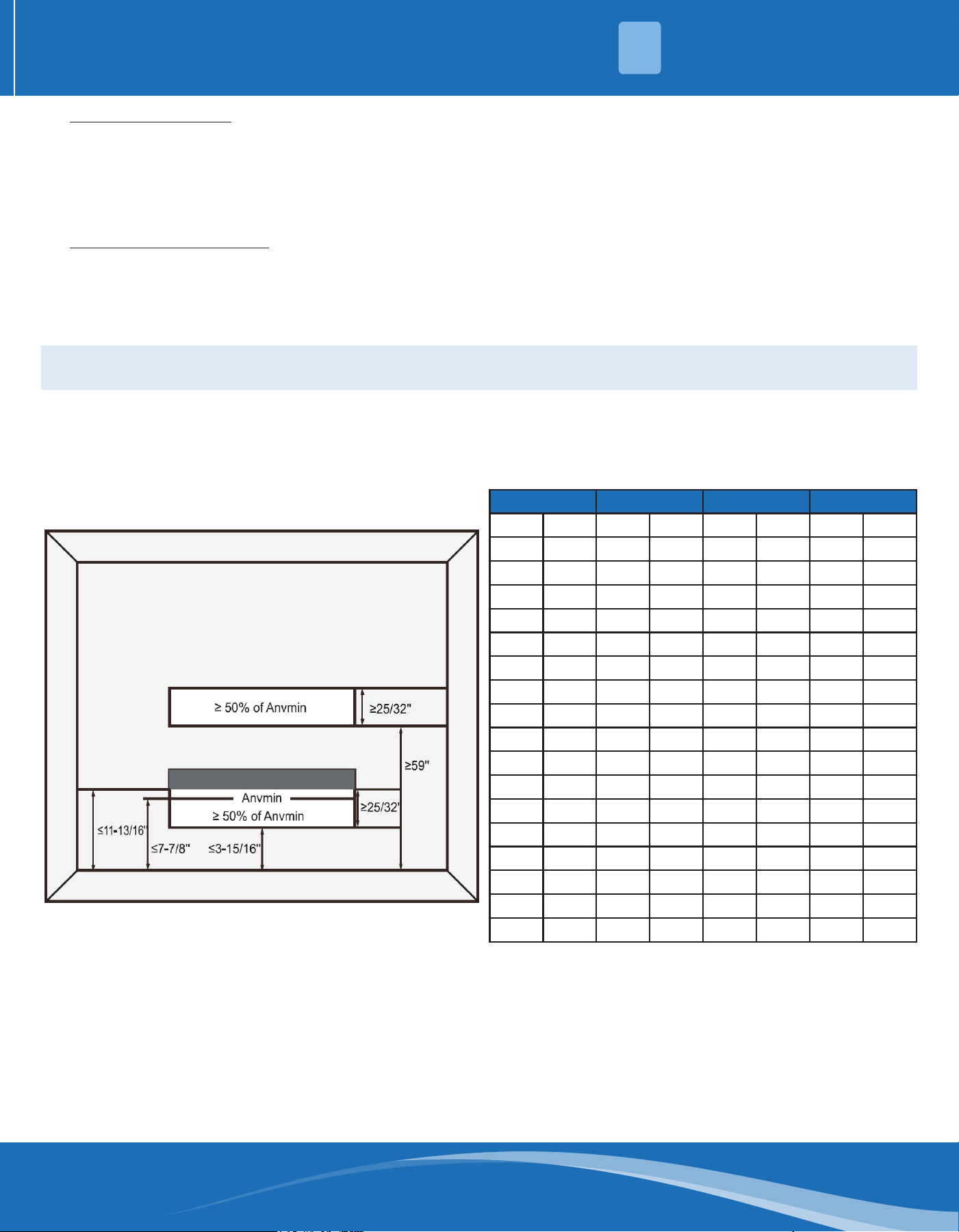
• The area of the connected rooms, on the same oor,connected by permanent opening in the walls and/or
doors between occupied spaces, including gaps between the wall and the oor, can be considered a single
room when determining compliance to Amin, provided all of the following conditions are met as those in the
gure.
• Low Level Opening
• The opening shall not be less than Anvmin in the following table.
• The area of any openings above 11.81 in (30cm) from the oor shall not be considered in determining
compliance with Anvmin.
• At least 50% of the opening area of Anvmin shall be below 7.88 in (20cm) from the oor.
• The bottom of the opening is not more than 3.94 in (10cm) from the oor.
• The opening is a permanent opening that cannot be closed.
• For openings extending to the oor the height shall not be less than 0.78 in (1.98cm) above the surface of
the oor covering.
mrcool.com 14
14
UNIT OVERVIEW
2
• High Level Opening
• The opening shall not be less than 50% of Anvmin in the following table.
• The opening is a permanent opening that cannot be closed.
• The opening shall be at least 59 in (1.49m) above the oor.
• The height of the opening is not less than 0.78 in (1.98m).
• Room Size Requirement
• The room into which refrigerant can leak, plus the connected adjacent room(s) shall have a total area no
less than Amin. Amin is shown in the following table
• The room area in which the unit is installed shall be no less than 20% Amin. Amin is shown in the
following table.
NOTE: The requirement for the second opening can be met by drop ceilings, ventilation ducts, or similar
arrangements that provide an airow path between the connected rooms.
• The minimum opening for natural ventilation (Anvmin) in connected rooms is related to the room area (A),
the actual ventilation (Anvmin) in connected rooms is related to the room area (A), the actual refrigerant
charge of refrigerant in the system (Mc), and the allowable maximum refrigerant charge in the system
(Mmax), Anvmin can be determined according to the following table.
A Mc Mmax Anvmin
ft
2
m
2
lb-oz kg lb-oz kg ft
2
m
2
100 11 17-3 7.8 6-10 3.0 1.3 0.14
110 12 17-3 7.8 7-5 3.3 1.2 0.13
120 13 17-3 7.8 8-0 3.6 1.1 0.12
130 14 17-3 7.8 8-10 3.9 1.0 0.11
140 16 17-3 7.8 9-5 4.2 1.0 0.11
150 17 17-3 7.8 10-0 4.5 0.9 0.10
160 18 17-3 7.8 10-10 4.8 0.8 0.09
170 19 17-3 7.8 11-5 5.1 0.7 0.08
180 20 17-3 7.8 12-0 5.4 0.6 0.07
190 21 17-3 7.8 12-10 5.7 0.5 0.06
200 22 17-3 7.8 13-5 6.0 0.5 0.06
210 23 17-3 7.8 14-0 6.4 0.4 0.04
220 24 17-3 7.8 14-10 6.6 0.3 0.03
230 26 17-3 7.8 15-5 6.9 0.2 0.02
240 27 17-3 7.8 16-0 7.3 0.1 0.01
250 28 17-3 7.8 16-10 7.5 0.1 0.01
260 29 17-3 7.8 17-5 7.9 0.0 0.00
• For appliances serving two or more rooms with an air duct system, the room area calculation shall
be determined based on the total area of the conditioned space (TA) connected by ducts taking into
consideration that the circulating airow distributed to all the rooms by the appliance integral indoor fan will
mix and dilute the leaking refrigerant before entering any room.
mrcool.com15
UNIT OVERVIEW
2
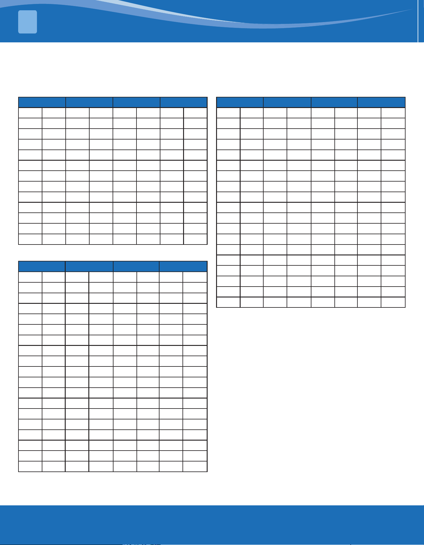
Allowed Maximum Refrigerant Charge & Required Minimum Room Area
• If the fan incorporated to an appliance is continuously operated or operation is initiated by a refrigerant
detection system with a sucient circulation airow rate, the allowable maximum refrigerant charge (Mmax)
and the required minimum room area (Amin/TAmin) is shown in the following tables.
A/TA Mmax A/TA Mmax
ft
2
m
2
lb-oz kg ft
2
m
2
lb-oz kg
30 2.8 2-0 0.9 150 13.9 10-0 4.5
40 3.7 2-9 1.2 160 14.9 10-9 4.8
50 4.6 3-5 1.5 170 15.8 11-4 5.1
60 5.6 3-14 1.8 180 16.7 11-15 5.4
70 6.5 4-9 2.1 190 17.7 12-9 5.7
80 7.4 5-3 2.4 200 18.6 13-4 6.0
90 8.4 5-14 2.7 210 19.5 14-0 6.4
100 9.3 6-9 3.0 220 20.4 14-12 6.7
110 10.2 7-5 3.3 230 21.4 15-7 7.0
120 11.1 7-15 3.6 240 22.3 16-0 7.3
130 12.1 8-9 3.9 250 23.2 16-12 7.6
140 13.0 9-4 4.2 260 24.2 17-13 7.9
Allowable Maximum Refrigerant Charge
Mc Amin/TAmin Mc Amin/TAmin
lb-oz kg ft
2
m
2
lb-oz kg ft
2
m
2
2-2 1.0 33.1 3.1 10-2 4.6 152.1 14.1
2-9 1.2 39.7 3.7 10-9 4.8 158.7 14.7
3-0 1.4 46.3 4.3 11-0 5.0 165.3 15.4
3-7 1.6 52.9 4.9 11-7 5.2 171.9 16.0
3-15 1.8 59.5 5.5 11-14 5.4 178.5 16.6
4-6 2.0 66.1 6.1 12-5 5.6 185.1 17.2
4-13 2.2 72.7 6.8 12-12 5.8 191.7 17.8
5-4 2.4 79.3 7.4 13-3 6.0 198.4 18.4
5-11 2.6 86.0 8.0 13-10 6.2 205.0 19.0
6-2 2.8 92.6 8.6 14-1 6.4 211.6 19.7
6-9 3.0 99.2 9.2 14-8 6.6 218.2 20.3
7-0 3.2 105.8 9.8 14-15 6.8 224.8 20.9
7-7 3.4 112.4 10.4 15-6 7.0 231.4 21.5
7-15 3.6 119.0 11.1 15-14 7.2 238.0 22.1
8-6 3.8 125.6 11.7 16-5 7.4 244.6 22.7
8-13 4.0 132.2 12.3 16-12 7.6 251.2 23.3
9-4 4.2 138.8 12.9 17-3 7.8 257.9 24.0
9-11 4.4 145.5 13.5
Required Minimum Room Area
Mc Qmin Mc Qmin
lb-oz kg CFM m
3
/h lb-oz kg CFM m
3
/h
2-2 1.0 59 100 10-2 4.6 275 467
2-9 1.2 71 121 10-9 4.8 287 488
3-0 1.4 83 141 11-0 5.0 298 506
3-7 1.6 95 161 11-7 5.2 310 527
3-15 1.8 107 182 11-14 5.4 322 547
4-6 2.0 119 202 12-5 5.6 334 567
4-13 2.2 131 223 12-12 5.8 346 588
5-4 2.4 143 243 13-3 6.0 358 608
5-11 2.6 155 263 13-10 6.2 370 629
6-2 2.8 167 284 14-1 6.4 382 649
6-9 3.0 179 304 14-8 6.6 394 669
7-0 3.2 191 325 14-15 6.8 406 690
7-7 3.4 203 345 15-6 7.0 418 710
7-15 3.6 215 365 15-14 7.2 430 731
8-6 3.8 227 386 16-5 7.4 442 751
8-13 4.0 239 406 16-12 7.6 454 771
9-4 4.2 251 426 17-3 7.8 466 792
9-11 4.4 263 447
Minimum Circulation Airow
mrcool.com 16
16
Charge
(lb)
Altitude (m)
201-400 401-600 601-800 801-1000 1001-1200 1201-1400 1401-1600 above 1600
Minimum Conditioned Space (m
2)
2 2.8 2.8 2.8 2.9 3.0 3.1 3.1 3.2
3 4.2 4.2 4.3 4.4 4.5 4.6 4.7 4.8
4 5.6 5.6 5.7 5.9 6.0 6.1 6.2 6.4
5 7.0 7.0 7.1 7.3 7.5 7.7 7.8 8.0
6 8.4 8.4 8.5 8.8 8.9 9.2 9.4 9.6
7 9.8 9.8 9.9 10.2 10.4 10.7 10.9 11.2
8 11.1 11.1 11.4 11.7 11.9 12.3 12.5 12.8
9 12.5 12.5 12.8 13.2 13.4 13.8 14.0 14.4
10 13.9 13.9 14.2 14.6 14.9 15.3 15.6 16.0
11 15.3 15.3 15.6 16.1 16.4 16.9 17.2 17.6
12 16.7 16.7 17.1 17.6 17.9 18.4 18.7 19.2
13 18.1 18.1 18.5 19.0 19.4 19.9 20.3 20.8
14 19.5 19.5 19.9 20.5 20.9 21.5 21.8 22.4
15 20.9 20.9 21.3 21.9 22.4 23.0 23.4 24.4
16 22.3 23.7 24.2 24.9 25.3 26.1 26.5 27.2
17 23.7 23.7 24.2 24.9 25.3 26.1 26.5 27.2
18 25.1 25.1 25.6 26.3 26.8 27.6 28.1 28.8
19 26.5 26.5 27.0 27.8 28.3 29.1 29.6 30.4
20 27.9 27.9 28.4 29.3 29.8 30.6 31.2 32.0
Required Minimum Room Area (If Installation Altitude >200m)
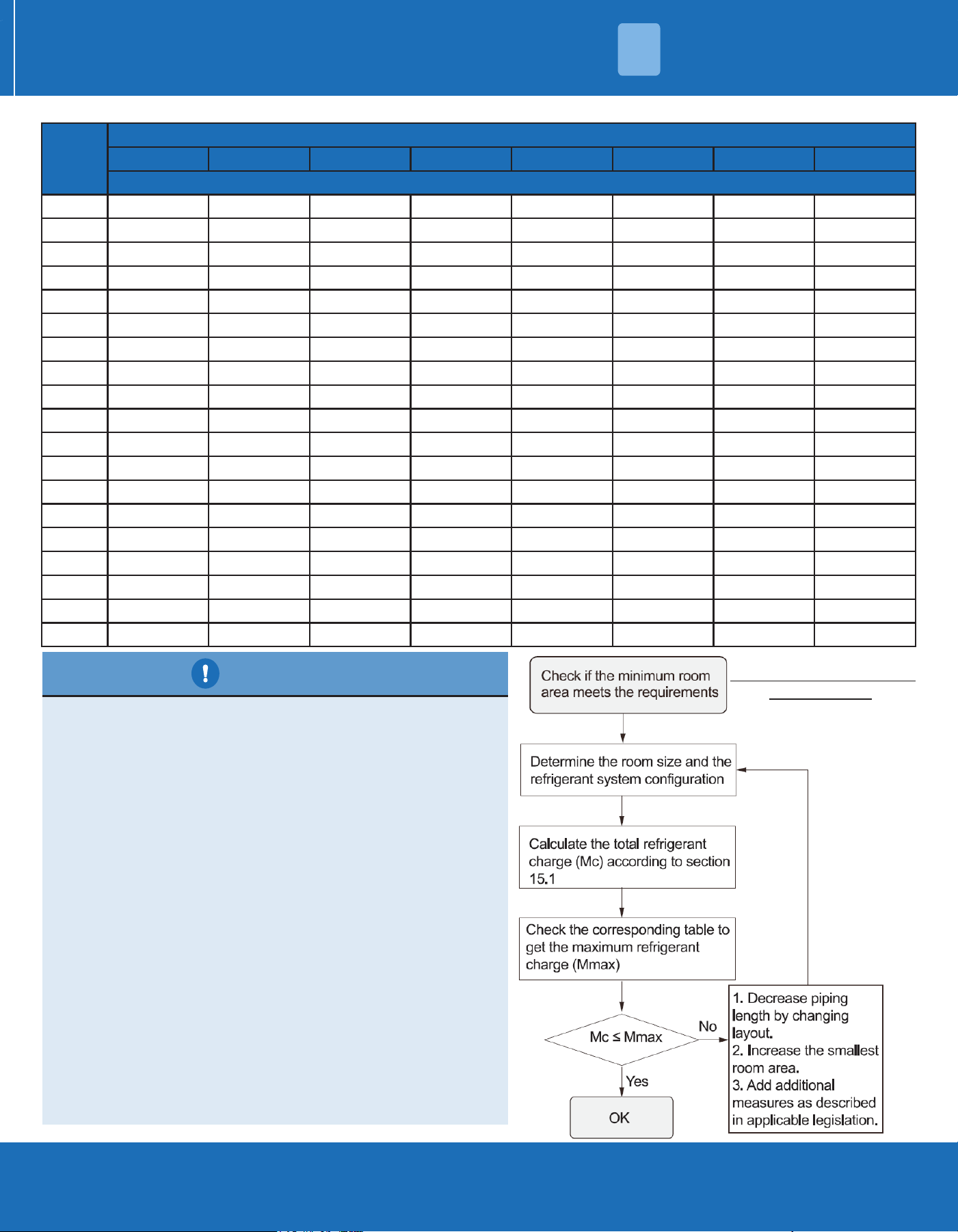
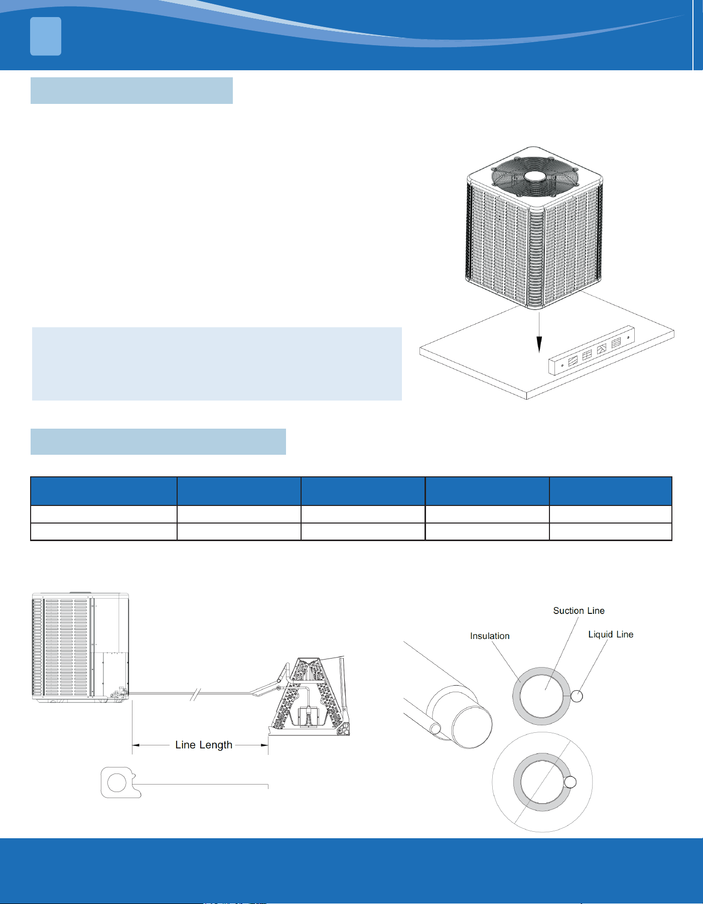
CAUTION
• The allowable maximum refrigerant charge or the
required minimum room area from the previous
tables is only available if the following conditions are
met: minimum velocity of 3.28ft/s (1m/s) which is
calculated as the indoor unit airow divided by the
nominal face area of the outlet. The grill area should
not be deducted. Minimum airow rate must meet the
corresponding values in the table, which is related to
the actual refrigerant charge of the system (Mc).
• The maximum refrigerant limit described applies to
unventilated areas. If adding additional measures,
such as areas with mechanical ventilation or natural
ventilation, the maximum refrigerant charge can be
increased or the minimum room area can be reduced.
• The R454B refrigerant leakage sensor is congured for
the indoor unit and meets the incorporated circulation
airow requirements. The maximum refrigerant
charge or minimum room area can be determined
according to the previous tables.
• If the actual room area, air outlet height, and
refrigerant charge amount are not reected in the
above table, more severe cases need to be considered
according to the data in the tables.
Installation Scheme
Flow Chart:
UNIT OVERVIEW
2
mrcool.com17
3.1 Installation Preparation
• Check whether there is any damage and report any damage to the unit to MRCOOL
®
.
• The ller can be used to ensure that the refrigerant charge is maintained during shipment.
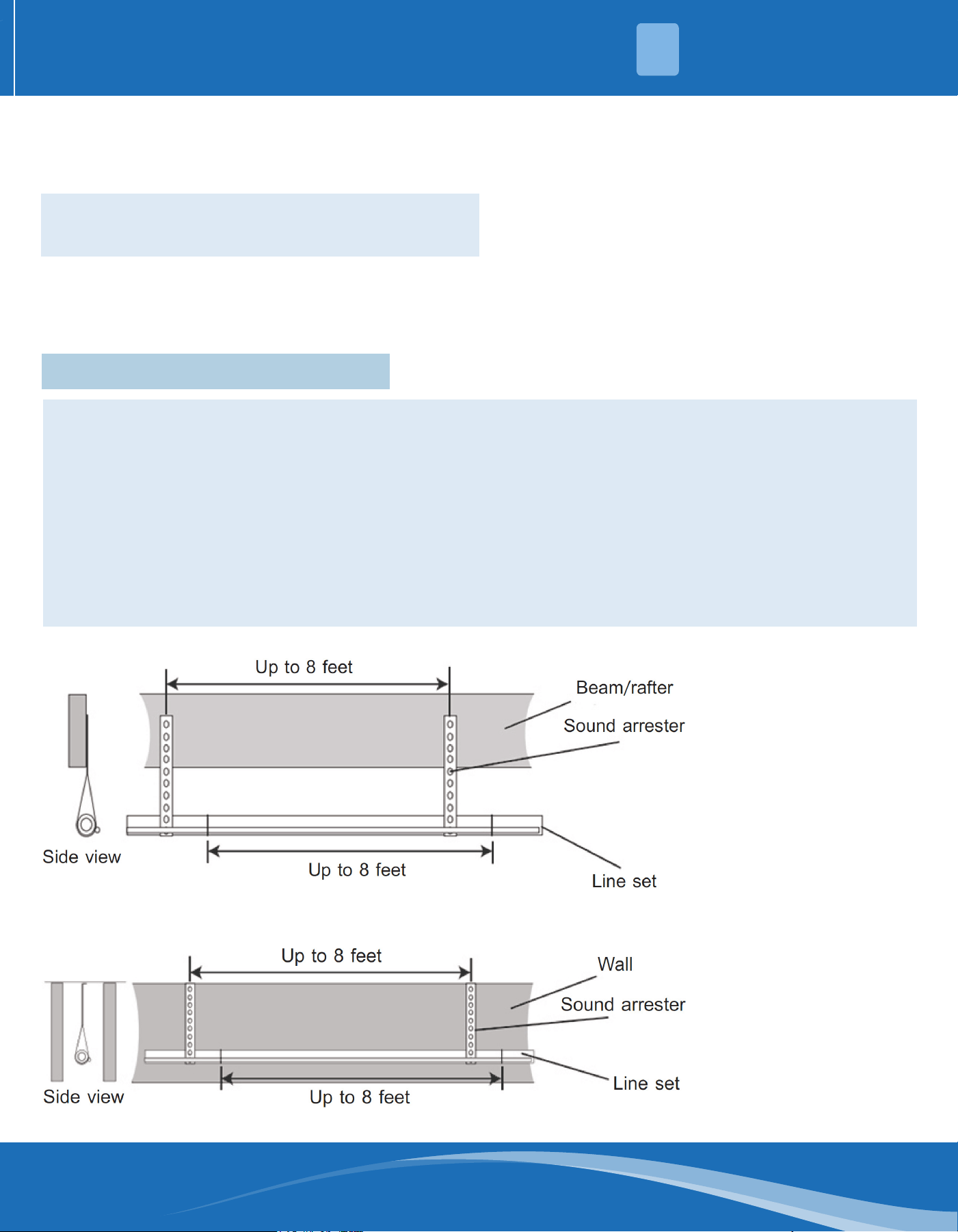
Gasket Installation
When installing the unit on a support pad (such as a concrete
slab), please consider the following:
• All sides of the pad must be at least 1-2 inches (2.5-5cm) larger
than the unit.
• The gasket must be separated from any structure.
• The mat must be level.
• The cushion must be high enough above the ground for
drainage.
• The location of the pad must comply with national, state, and
local regulations.
Note:
These instructions are intended to provide a method of xing
the system to the cement slab as a xing procedure in windy
areas. Check the local regulations of tie-down methods and
protocols.
INSTALLATION
3
3.2 Refrigerant Line Precautions
Model Suction Line Liquid Line
Suction Line
Connection
Liquid Line
Connection
18K / 24K / 30K / 36K / 42K 3/4" 3/8" 3/4" 3/8"
48K / 60K 7/8" 3/8" 7/8" 3/8"
Connecting Dimensions for Refrigerant Lines & Service Valves
Length of Required Refrigerant Pipeline
Determine the required pipeline length.
Refrigerant Pipe Insulation
The air pipe must always be insulated. Do not let
the liquid pipeline and gas pipeline come into direct
contact (metal to metal).
mrcool.com 18
18
INSTALLATION
3
Reuse Existing Refrigerant Lines
The air pipe must always be insulated. Do not let the
liquid pipeline and gas pipeline come into direct contact
(metal to metal).
Note:
If using existing refrigerant lines, make sure that all
joints are brazed, not soldered.
The following precautions should be taken for
the retrot application that will use the existing
refrigerant pipeline:
• Make sure the refrigerant line size is correct.
• Make sure the refrigerant line is free of leakage,
acid, and oil.
The manufacturer recommends that only approved matching indoor and outdoor systems be installed. All split
systems are certied by AHRI, the indoor unit is equipped with piston or TXV, and the model of piston and TXV is
selected by manufacturer; please do not change by yourself. The benets of installing an approved indoor and
outdoor split system are maximum eciency, best performance, and best overall system reliability.
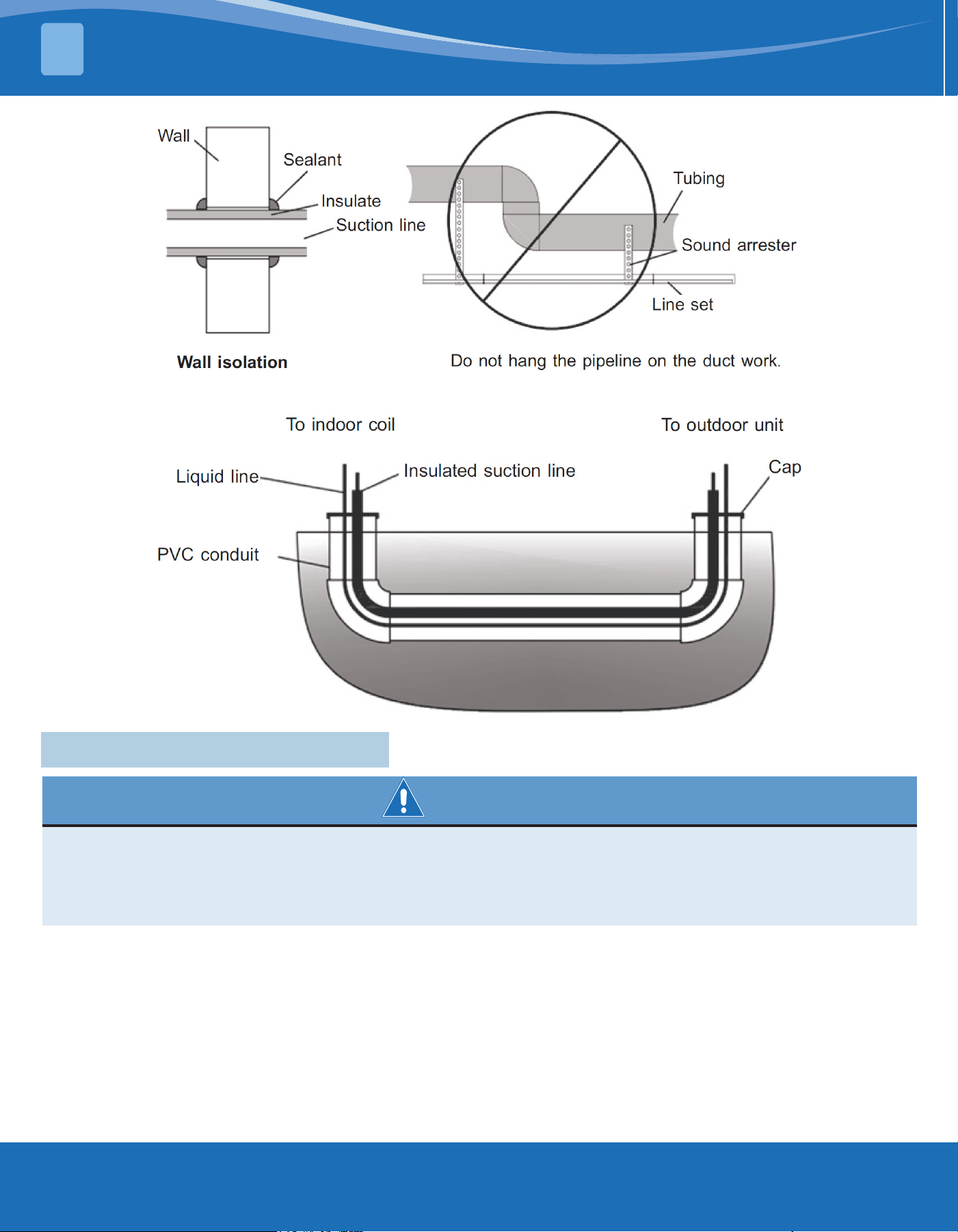
3.3 Refrigerant Pipeline Routing
Note:
Take preventative measures to prevent noise generated by vibration transmission of refrigerant pipeline in
building structure. For example:
• When the refrigerant pipeline must be xed on oor joists or other frames in the structure, use isolated
hangers.
• When the refrigerant pipeline runs in the column space or closed ceiling, the isolation hanger should also
be used.
• When refrigerant lines pass through walls or windowsills, they should be insulated and isolated.
• Isolate the pipeline from all piping systems.
• Try to reduce the number of 90° laps.
Comply with national, state, and local regulations when isolating the wire group from joists, rafters, walls, or
other structural elements.
Isolated from beam/rafter:
Use isolators to x the
air pipes on the beams
every 8 feet (2.44m). Every
8 feet (2.44m), tape, wire,
or other suitable methods
are used to x the liquid
line directly to the suction
line.
Isolated on the wall:
Use isolators to x the
suction line every 8 feet
(2.44m). Every 8 feet
(2.44m), tape, wire, or
other suitable methods
are used to x the liquid
line directly to the suction
line.
mrcool.com19
INDOOR UNIT INSTALLATION
3
3.4 Refrigerant Line Connection
• Pipe work and installation should be in compliance with national codes ASHRAE15.
• The installation of pipe-work should be kept to a minimum.
• It is recommended to install a lter dryer. The dryer should be installed in the liquid line between the
outdoor unit's liquid line service valve and the indoor coil's metering device.
• The lter dryer should be compatible with R454B refrigerant.
WARNING
• All joints made in the installation between parts of the refrigerating system, with at least one part charged,
shall be made in accordance with the following:
• A brazed, welded, or mechanical connection should be made before opening the valves to permit
refrigerant to ow between the refrigerating system parts. A vacuum valve shall be p0rovided to evacuate
the interconnecting pipe or any uncharged refrigerating system part.
• Mechanical connectors used indoors shall comply with ISO 14903. When mechanical connectors are reused
indoors, sealing parts shall be renewed. When ared joints are reused indoors, the are part shall be re-
fabricated.
• Refrigerant tubing shall be protected or enclosed to avoid damage.
• Flexible refrigerant connectors (such as connecting lines between the indoor and outdoor unit) that may be
displaced during normal operation shall be protected against mechanical damage.
mrcool.com 20
20
INDOOR UNIT INSTALLATION
3
• Compliance is checked according to the installation instructions and a trial installation, if necessary.
• Field-made refrigerant joints indoors shall be tightness tested. The test method shall have a sensitivity of
5 grams per year of refrigerant or better under a pressure of at least 0.25 times the maximum allowable
pressure. No leak shall be detected.
• For installations with eld applied joints that are exposed in the occupied space,these joints shall be at least
one of the following:
• Mechanical joints in compliance with ISO 14903 or UL 207 (U.S. only).
• Welded or brazed joints.
• Joints in enclosures that vent to the unit or to the outside.
• Compliance is checked by inspections and tests.
3.5 Refrigerant Pipeline Brazing
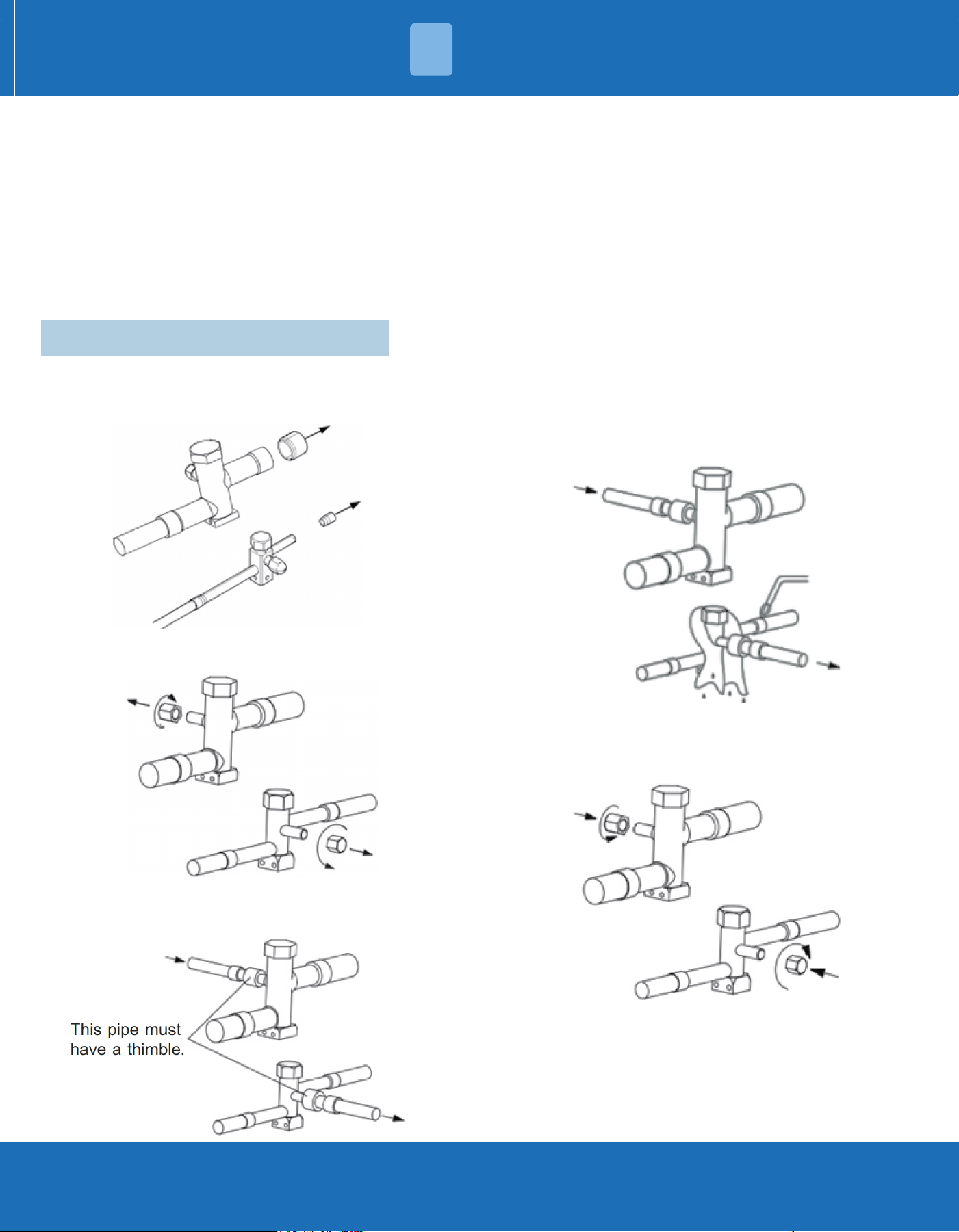
1. Remove the cover or plug. Use the deburring tool
to deburr the pipe end. Clean the inner and outer
surfaces of the pipeline with emery cloth.
2. Remove the pressure taps from the two service
valves.
3. Purge refrigerant lines and indoor coils with dry
nitrogen.
4. Wrap the valve body with a wet rag to avoid
thermal damage, and continue the dry nitrogen
purging. Braze the refrigerant line to the service
valve. Continue the dry nitrogen purge. Don't take
o the wet rag before all brazing is completed.
5. After the service valve cools down, replace the
pressure tap.
mrcool.com21
3.6 Leakage Check
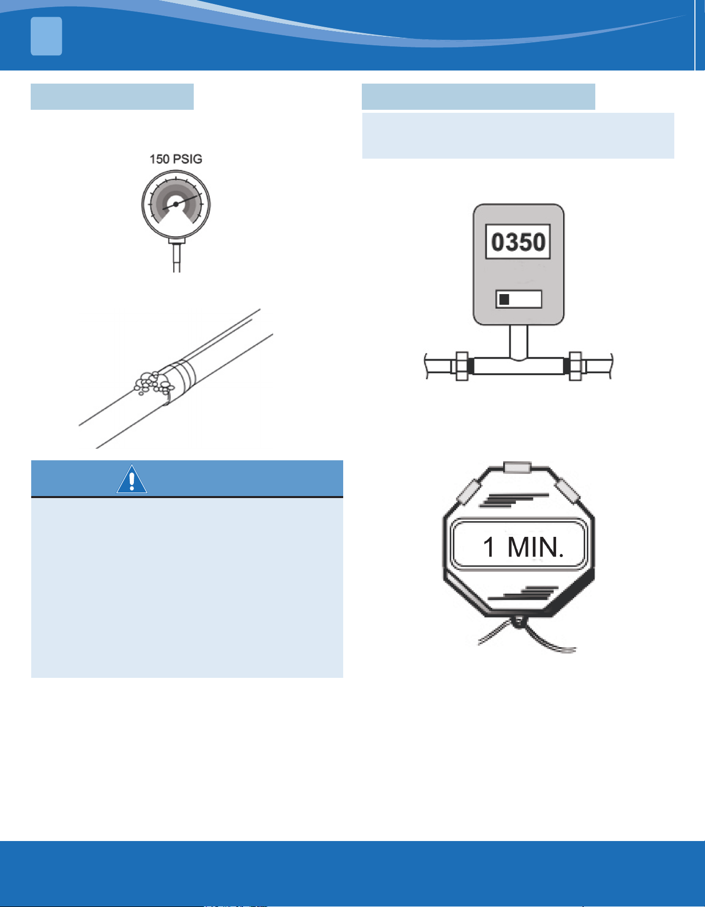
1. Use dry nitrogen to pressurize the refrigerant line
and evaporator coil to 150 PSIG.
2. Use soapy water or foam at each soldering
position to check for leaks.
• After completion of eld piping for split systems,
the eld pipework should be pressure tested
with an inert gas and then vacuum tested
prior to refrigerant charging, according to the
following requirements:
• Entire line set and evaporator coil should
hold 600 psig for 1 hour.
• Field-made refrigerant joints indoors should
be tightness-tested. The test method should
have a sensitivity of 5 grams per year of
refrigerant or better under a pressure of
at least 0.25 times the maximum allowable
pressure. No leak should be detected.
WARNING
3.7 Emptying Pipeline & Coil
1. Evacuate until the micrometer reading is not
higher than 350 micrometers, and then close the
valve of the vacuum pump.
NOTE: Do not open the service valve until the
leakage inspection and emptying of refrigerant lines
and indoor coils are completed.
2. Observe micrometer gauge. If the meter does not
rise above 500 micrometers within (1) minute, the
evacuation is completed. After the evacuation, turn
o the vacuum pump and micrometer, and close
the valve on the manifold instrument cluster.
INDOOR UNIT INSTALLATION
3
mrcool.com 22
22
3.8 Open the Service Valve
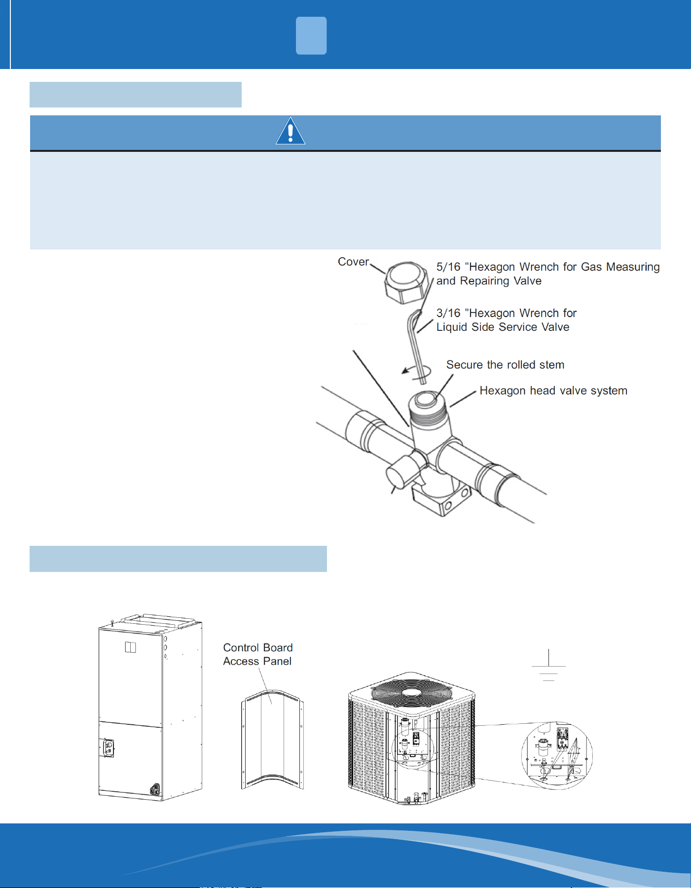
• When opening the liquid side service valve, be extra careful. Turn counterclockwise until the valve stem
just touches the hem. No torque is required. Failure to observe this warning will result in sudden release of
system pressure, and may result in personal injury and/or property damage.
• Before opening the service valve, the leakage inspection and emptying must be completed. The valve of
copper welded pipe installation should be used for leakage inspection and vacuum pumping. The use of a
separate suction port in this process will lead to refrigerant loss.
• Before opening the liquid side service valve, the gas side service valve must be opened rst.
WARNING
Device side of
overhaul valve
1. Remove the valve cover.
2. Insert the hex wrench into the
valve stem completely and back out
counterclockwise until the valve stem just
touches the bead.
3. Replace the valve stem cap to prevent
leakage. Tighten it with your ngers and
turn it for another 1/6 turn.
4. Repeat steps 1-3 for the liquid side
service valve.
3.9 Low Voltage Electrical Connections
INDOOR UNIT INSTALLATION
3
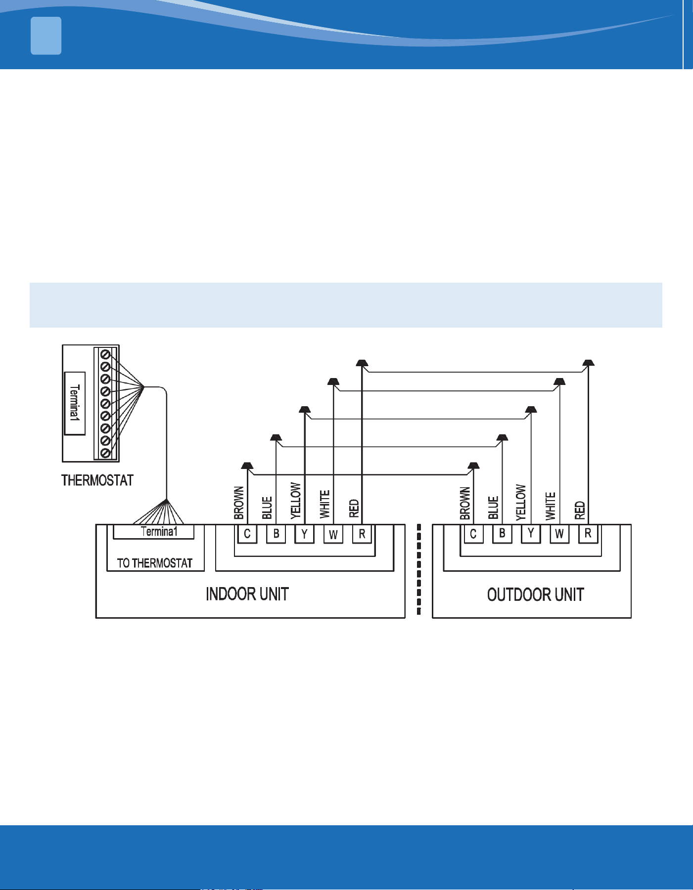
Low Voltage Connection Diagram
mrcool.com23
INDOOR UNIT INSTALLATION
3
• Ensure that the power supply is consistent with the nameplate of the unit.
• The power connection and grounding of the unit must comply with local regulations.
• Low-voltage wiring is the smallest conductor of No. 22AWG.
• "-----" On-site installation of electrical auxiliary thermal connection
• Single-stage electric auxiliary heating supported by 2H thermostat.
• Two-stage electric auxiliary heating supported by 3H thermostat.
• W1: The rst stage of electric auxiliary heating installed in the indoor unit
• W2: The second stage of electric auxiliary heating installed in the indoor unit
• The W signal of the outdoor unit is connected to the electric auxiliary heating or the rst stage auxiliary heat.
NOTE: The dotted line in the following thermostat wiring diagram indicates optional wiring (electric heating).
For the wiring of the thermostat, please refer to the user manual of the thermostat. Terminal B will be
connected with the thermostat (O/B) wiring. The reversing valve is energized during heating.
Thermostat Wiring Diagram
mrcool.com 24
24
INDOOR UNIT INSTALLATION
3
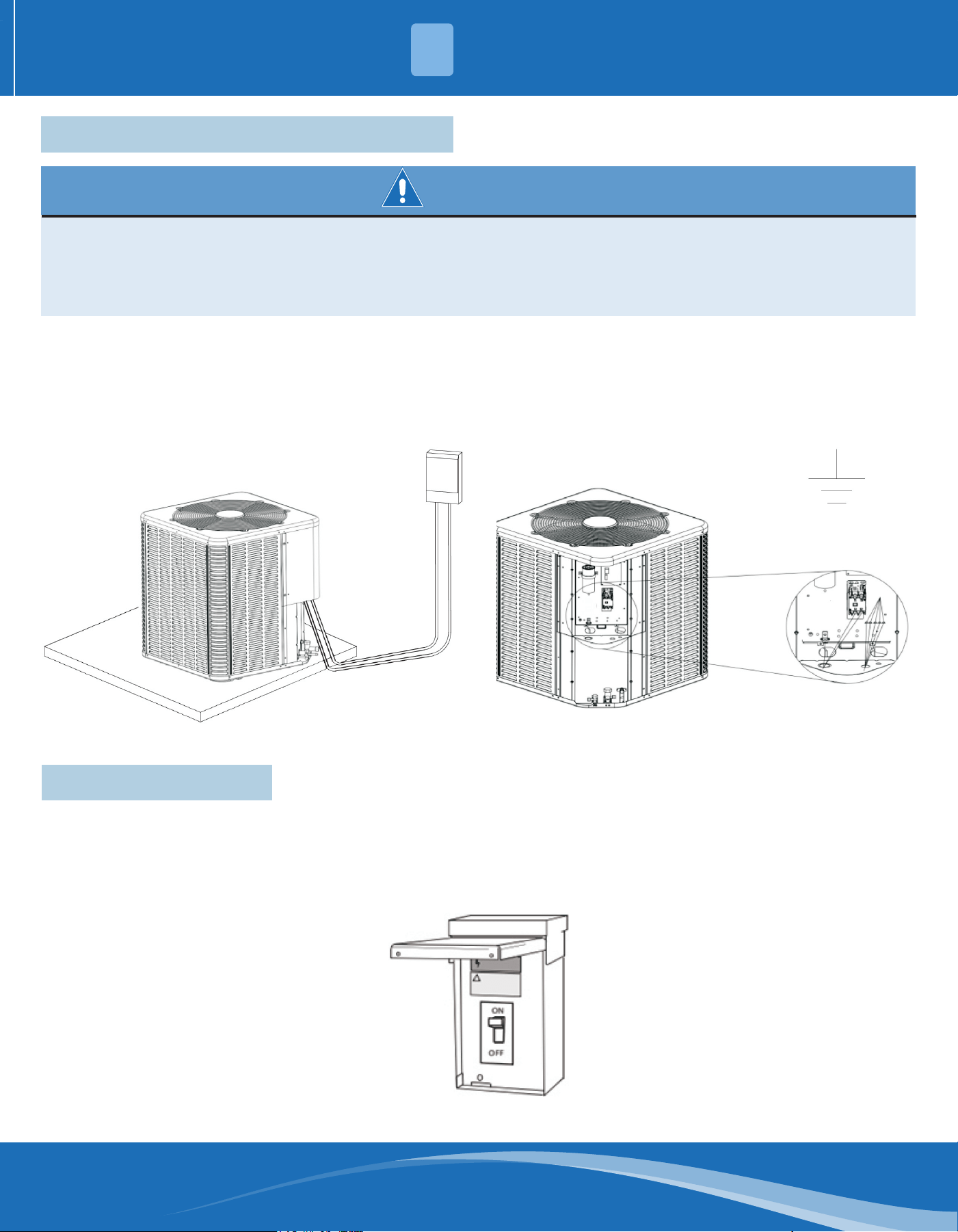
3.10 High Voltage Electrical Connections
• During the installation, testing, maintenance, and troubleshooting of this product, it may be necessary to
use live electrical parts. Failure to observe all electrical safety precautions when exposed to live electrical
parts may result in death or serious injury.
• The high voltage power supply must match the nameplate of the unit (208/230V, 1PH, 60Hz).
• Power supply wiring must comply with national, state, and local regulations.
WARNING
Follow the instructions of the unit wiring diagram located inside the access panel of the control box, and refer to
the wiring diagram in this manual.
High Voltage Isolating Switch High Voltage Grounding
Ground the outdoor unit according to the
requirements of national, state, and local regulations.
Install a separate disconnect switch on the outdoor
unit. High voltage wiring must use exible electrical
conduit supplied on site.
3.11 System Startup
1. Make sure that all previous installation steps have been completed.
2. Set the thermostat to o.
3. Turn on the disconnect switch and turn on the power of the indoor and outdoor unit.
4. Set the thermostat to on.
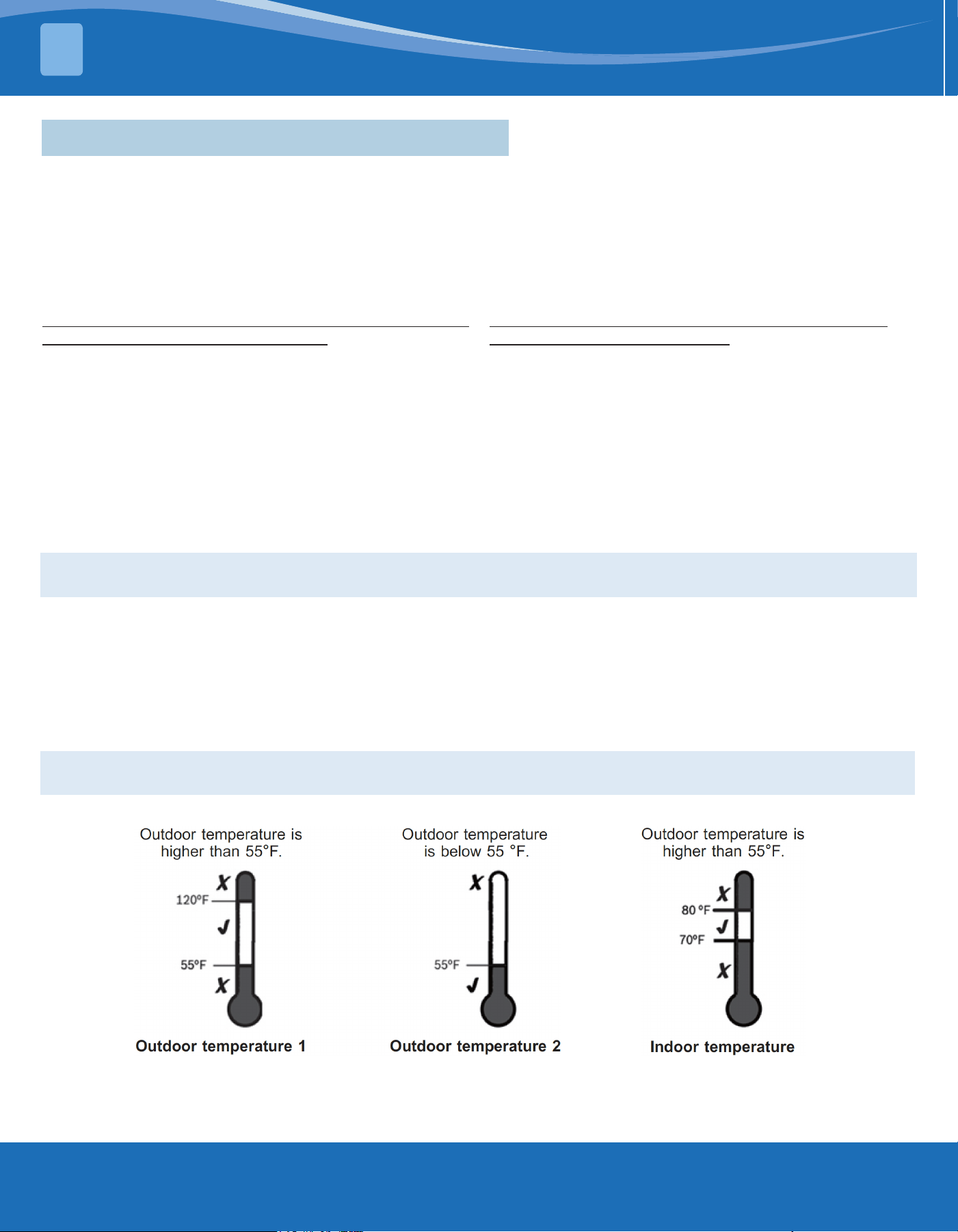
mrcool.com25
3.12 System Refrigerant Charging Regulation
Charging: Weighing Method
During the initial installation, or when the refrigerant quantity of the updated system is charged, the weighing
method is used. When there is no power supply at the site of the unit or the operating conditions (indoor/
outdoor temperature) are not within the range veried by sub-cooling charging method. All models have a
charge factor of 0.69oz/ft for refrigerant pipe length.
For a 25-foot standard size interconnecting liquid pipe, the factory refrigerant charge of the outdoor unit is
sucient.
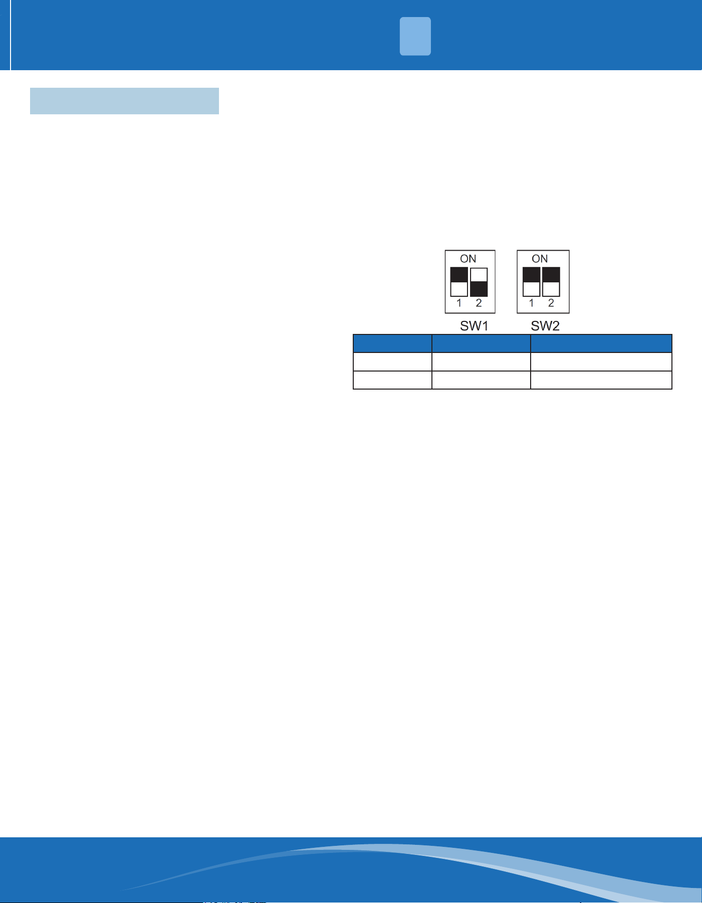
Note: The only mode approved for verifying system charging is in "forced cooling mode". The outdoor
temperature must be between 55°F and 120°F and the indoor temperature should be between 70°F and 80°F.
Subcooling Charging & Refrigerant Quantity Adjustment in Cooling Mode
1. Check the outdoor ambient temperature.
Subcooling (cooling mode) is the only recommended charging method when the outdoor ambient temperature
is higher than 55°F (12°C).
For outdoor ambient temperature below 55°F (12°C), use the weighing charging method.
Note: When the outdoor ambient temperature is higher than 55°F, be sure to return in spring or summer, so
as to accurately charge the system in cooling mode.
New Installation-Calculate the charging amount of
connecting pipes larger than 25 ft.
1. Total Length of Pipeline (ft) = ____________ (a)
2. Standard Piping Setup (ft) = _______________ (b)
3. (a) minus (b) = _______________ (c)
4. Refrigerant Multiplier = 0.69 oz/ft (d)
5. Additional Refrigerant Quantity (c*d) = ________ (e)*
*If the line set is less than 25 feet, e=0
Closed System Maintenance-Calculate the total
lling amount of the system.
1. Total length of pipeline (ft) = _______________ (a)
2. Standard Piping Setup (ft) = 25 (b)
3. (a) minus (b) = _______________ (c)
4. Refrigerant Multiplier = 0.69 oz/ft (d)
5. Additional refrigerant quantity (c*d) = _________ (e)*
6. Factory Filling Quantity (nameplate) = ___________ (f)
7. Total System Charge (e+f) = _______________
*If the line set is less than 25 feet, e=0
For best results, the indoor temperature should be kept between 70°F (21°C) and 80°F (26°C) during installation.
2. Ensure that all installation steps have been completed.
INDOOR UNIT INSTALLATION
3
mrcool.com 26
26
POST-INSTALLATION
4
4.1 System Operation
Control Logic Description
The system uses universal 24V control.
Sensors
• T3 - Outdoor unit coil temperature
• T4 - Ambient temperature
• T5 - Compressor exhaust temperature
• LP - Low pressure switch
Description of Defrosting
• Outdoor unit W terminal will output 24V signal
during defrost mode.
• Unit will run defrost mode in the following
conditions:
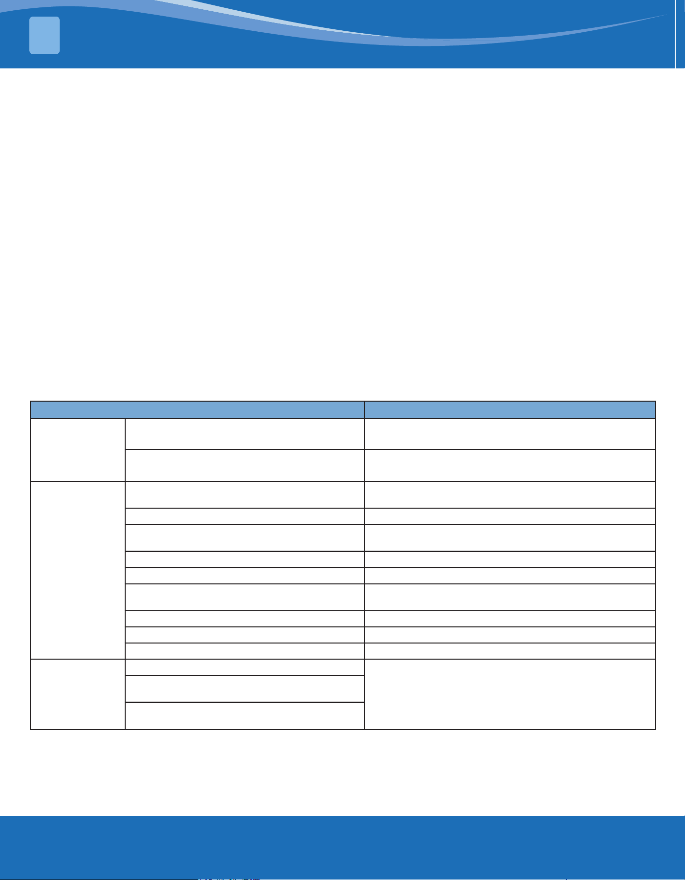
1. Unit run in heating mode
2. Compressor is running
3. Defrost mode and cycle time is related with
SW1-2 and SW1-3 dial switch
Dial Switch SW1-2 SW1-3
OFF Defrost Mode 2 Cycle Time: 60 Minutes
ON Defrost Mode 1 Cycle Time: 30 Minutes
I. When SW1-2 is ON, unit will run defrost mode 1 when it meets any of the following conditions:
• Condition 1: When the compressor starts, the unit will record minimum T3 which named T30, and
minimum T4 which named T40 during compress start 10-15mins. When outdoor unit meets the
following condition, the unit will run defrost mode:
a) When T3<0, and compressor runs for 40 minutes
b) Unit calculate ∆T4=T4-T40 (If ∆T4≤2, unit will result ∆T4=0), and T3 + 2 < (T30+ ∆T4) keep 30s.
• Condition 2: When T3<0, and compressor runs for 40 minutes, and T3<-4°F(-20°C), unit will
defrost.
II. When SW1-2 is off, the unit will run defrost mode 1 when it meets any of the following conditions:
• Condition 1:
a) SW1-3 is on, and compressor is running, when T3<30°F (-1°C) and keep 30 minutes, unit will run
defrost.
b) SW1-3 is off, and compressor is running when T3<30°F (-1°C) and keep 60 minutes, unit will run
defrost.
• Condition 2: When unit power is on, and compressor starts for the first time, and T3 <28°F (-2°C),
unit will run defrost.
• Condition 3: When unit standby for 2 hours, and T3<28°F (-2°C), unit will defrost.
4. Quit defrost condition:
I. When SW1-2 is on, unit will quit defrost when it meets any below condition:
• Condition 1: Defrost time is last 10 minutes
• Condition 2: T3 ≥ 59°F (15°C)
II. When SW1-2 is off, unit will quit defrost when it meets any below condition:
• Condition 1: Defrost time is last 10 minutes
• Condition 2: T4 ≥ 28°F (-2°C), T3 ≥ 77°F (25°C)
• Condition 3: Compressor stop
• Condition 4: T4 <28°F (-2°C), T3 ≥ 77°F (25°C) and keep 60 seconds.
mrcool.com27
POST-INSTALLATION
4
Compressor Crankshaft Heater Control Function
The crankshaft heater logic is below:
1. Crankshaft heater on condition:
When unit meets any of the below conditions, crankshaft heater will be on:
Condition 1: Meet 3 conditions at the same time below
• T5 < 73°F (23°C) or T5 sensor is abnormal
• Outdoor unit is in standby mode, and T4 was lower 50°F (10°C) before.
• Outdoor unit stop time ≥ 4 hours.
Condition 2:
• Outdoor unit power on, and T5 < 23°C
• Outdoor unit is in defrost mode, and T5 <73°F (23°C).
2. Crankshaft heater o condition
T5 ≥ 82°F (28°C) and no T5 error
Four-Way Valve Operating Condition
Four-way valve will power on in heating mode, and power o in cooling mode.
Display Content State Description
No alarm:
Green light ashes
Red light o
Green light slow ashes Normal standby
Green light normally on Normal operation
System alarm:
Red light on
Green light ashes
High pressure alarm Green light ashes 1 time every 8 seconds
(T3) Temperature sensor fault Green light ashes 2 times every 8 seconds
Outdoor low temperature protection function
(CUT-OUT/CUT-IN)
Green light ashes 3 times every 8 seconds
Phase sequence detection fault Green light ashes 4 times every 8 seconds
High exhaust temperature protection Green light ashes 5 times every 8 seconds
Low pressure alarm
Green light ashes 6 times every 8 seconds (If the compressor
is turned on, then there will be a 60-second delay.)
(T5) Temperature sensor fault Green light ashes 8 times every 8 seconds
(T4) Temperature sensor fault Green light ashes 9 times every 8 seconds
(T3) High temperature protection Green light ashes 10 times every 8 seconds
System has locked
up:
Green light o
Red light ashes
Three high/low pressure alarm within 20 minutes
The machine can only operate when it is powered on again.
Three instances of excessively high exhaust
temperature within 20 minutes
Three instances of T3 high-temperature protection
within 20 minutes
Outdoor Unit Main PCB LED Display & Fault Table
mrcool.com 28
28
POST-INSTALLATION
4
4.2 Troubleshooting of Fault Codes
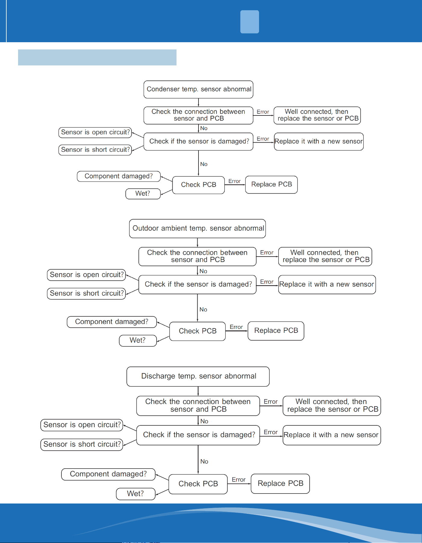
T3 Condenser Temperature Sensor Error
T4 Outdoor Ambient Temperature Sensor Error
T5 Discharge Temperature Sensor Error
mrcool.com29
POST-INSTALLATION
4
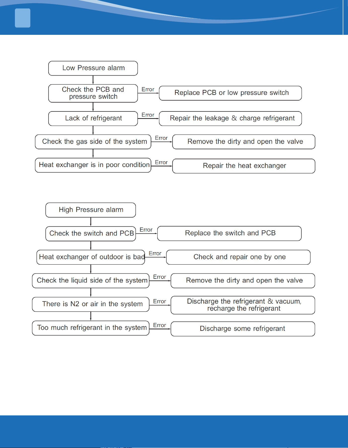
High Pressure Alarm
Low Pressure Alarm
mrcool.com 30
30
POST-INSTALLATION
4
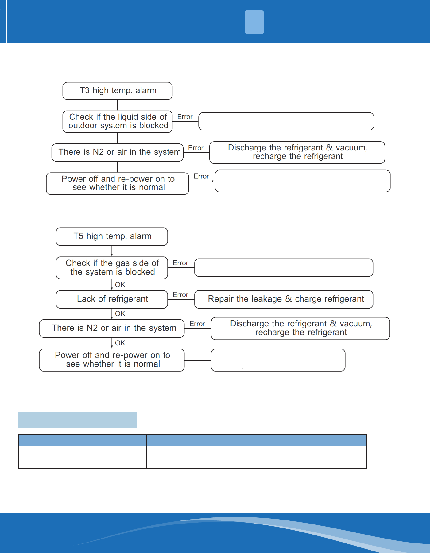
T3 High Temperature Alarm
T5 High Temperature Alarm
Remove the blockage and open the valve.
If there are still abnormalities, replace the
mainboard.
If there are still abnormalities,
replace the mainboard.
Remove the blockage and open the valve.
4.3 Operation Limits
Mode/Temperature Cooling Operation Heating Operation
Room Temperature 63°F~86°F (17°C~30°C) 63°F~86°F (17°C~30°C)
Outdoor Temperature 59°F~113°F (15°C~45°C) 5°F~90°F (-15°C~32°C)
NOTICE: Ton=5°F, To=2°F
mrcool.com31
POST-INSTALLATION
4
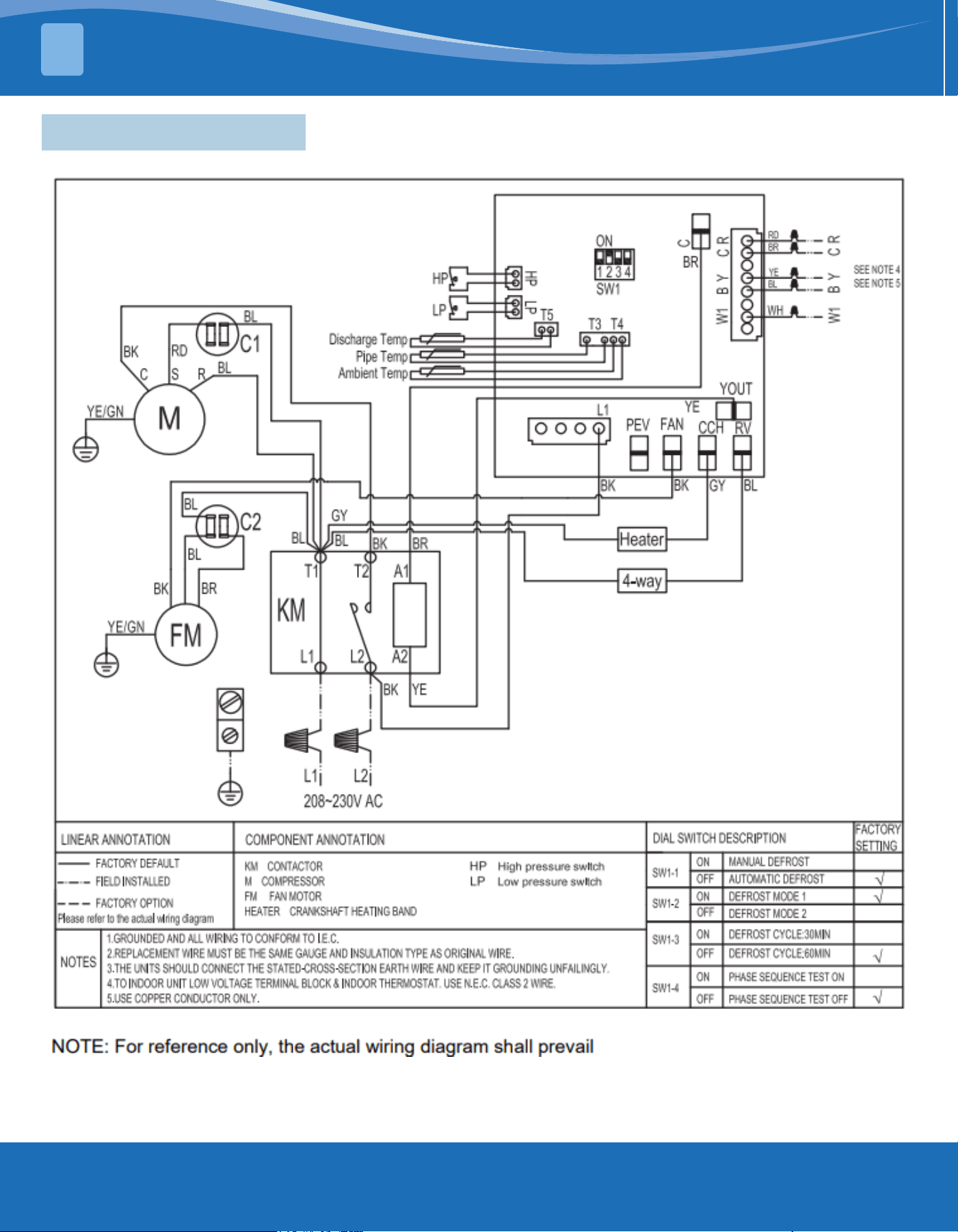
4.4 Wiring Diagram
mrcool.com 32
32
POST-INSTALLATION
4
4.5 Cleaning Precautions
• Any cleaning of outdoor units can only be carried out by qualied maintenance personnel.
• Any unit maintenance can only be carried out by qualied maintenance personnel.
WARNING
CAUTION
• Be sure to turn o the unit and disconnect the power supply before cleaning or maintenance.
• Do not use chemicals or chemically treated cloth to clean the unit.
• Do not use benzene, paint thinner, polishing powder, or other solvents to clean this unit.
• When removing the lter, do not touch the metal parts in the unit. Sharp metal edges can cut you.
4.6 Pre-Season Inspection & Maintenance
At the start of each heating or cooling season, do the following:
Turn o the unit and disconnect the power supply.
Check for damaged wires.
Check for leaks.
Make sure that all air inlets and outlets are not blocked.

MRCOOL
®
Signature Series
Split System Heat Pump
The design and specications of this product and/or manual are subject to change without prior notice.
Consult with the sales agency or manufacturer for details.