Read this manual carefully before installation and keep it where the
operator can easily nd it for future reference.
Due to updates and constantly improving performance, the information
and instructions within this manual are subject to change without
notice.
Version Date: August 26, 2025
Please visit www.mrcool.com/documentation
to ensure you have the latest version of this manual.
This product utilizes R-454B refrigerant
MPH*1HO13C
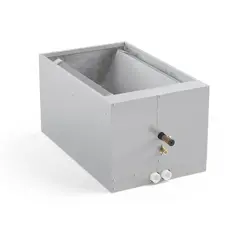
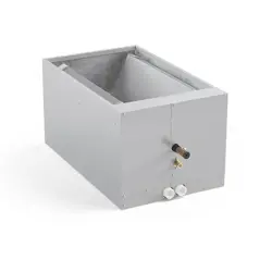
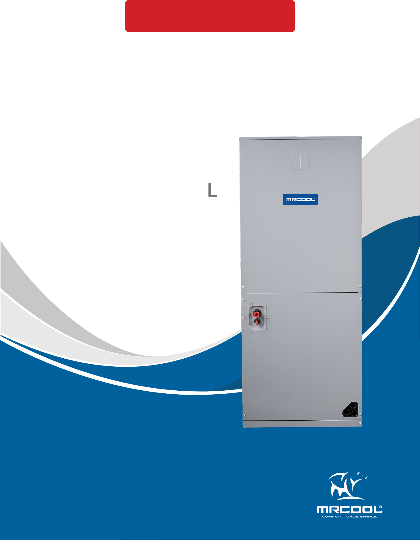
MRCOOL® Signature
Series Multi-Position
Air Handler
INSTALLATION &
OWNER'S MANUAL
MODELS:
• MCAEAMPSF*C21AA
• MCAEAMPEF*C21AA
• MCAEAMPEF*E21AA

mrcool.com1
CONTENTS
SAFETY ......................................................................................................... 2
UNIT OVERVIEW .......................................................................................... 8
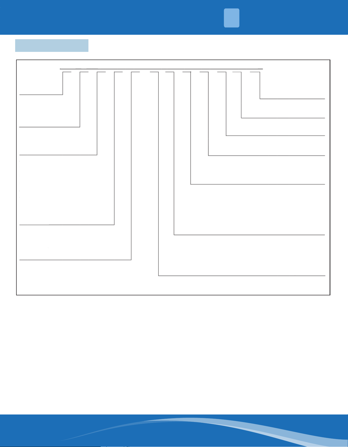
2.1 Nomenclature ................................................................................. 8
2.2 Unit Information ............................................................................ 9
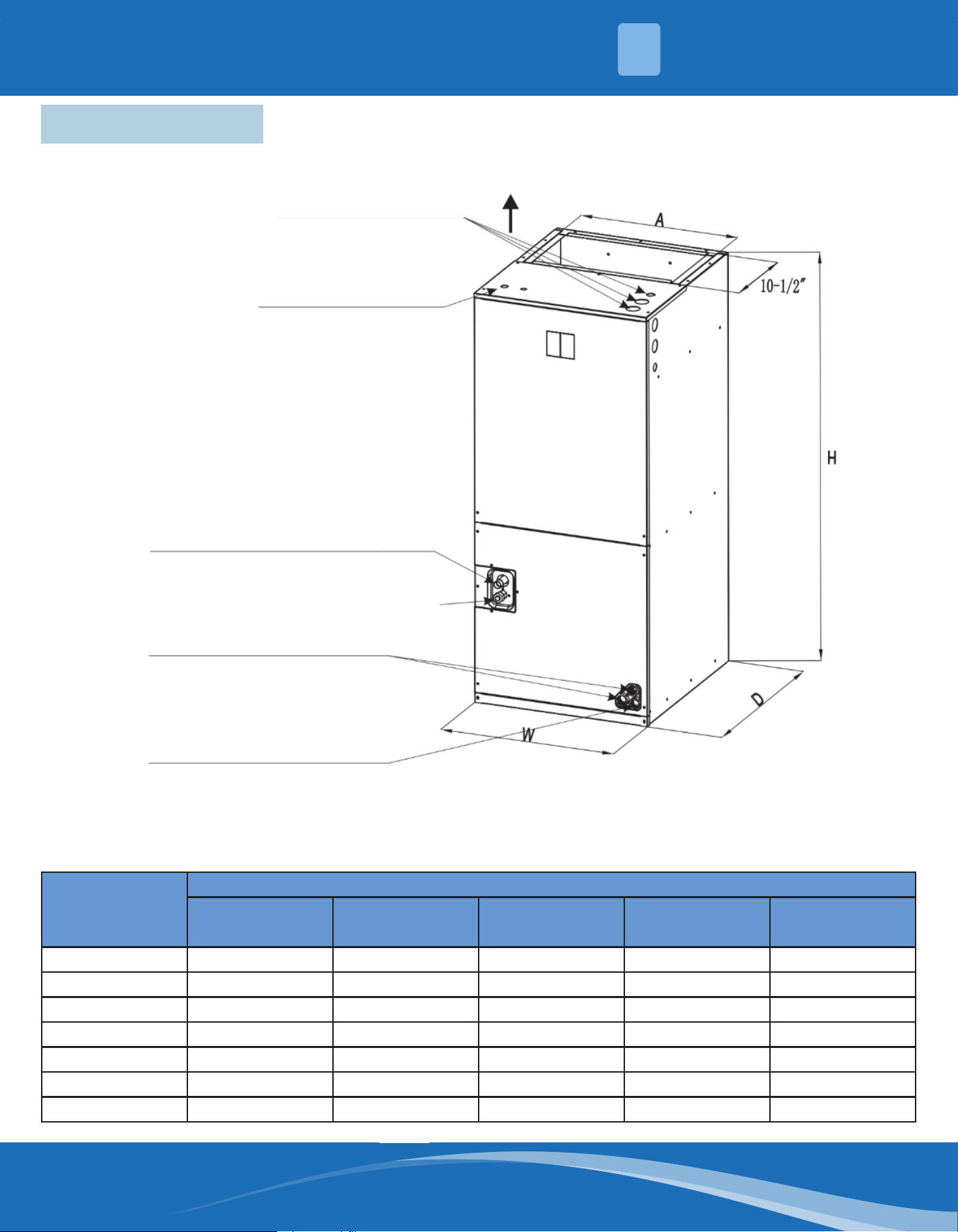
2.3 Unit Dimensions ........................................................................... 10
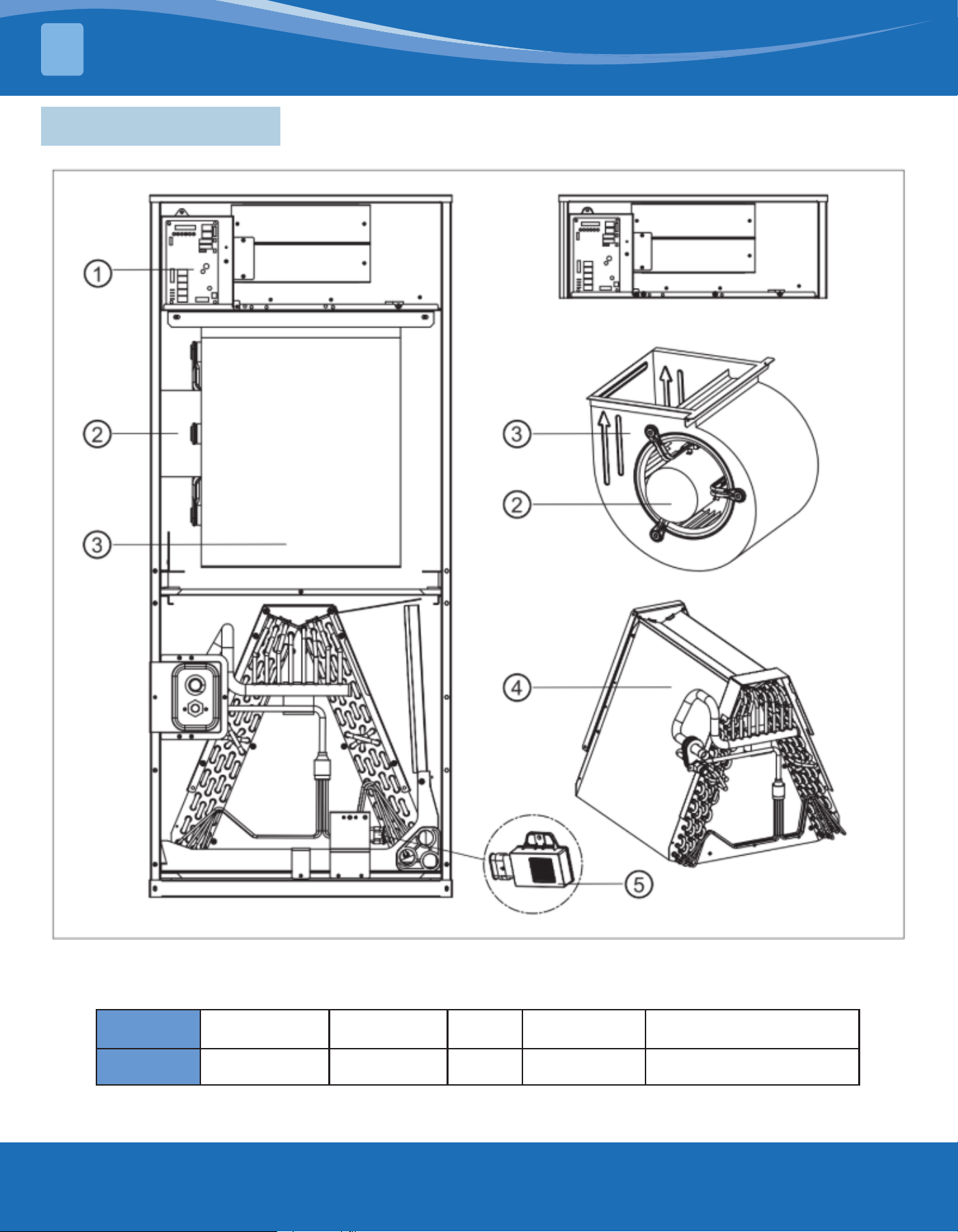
2.4 Parts Introduction ........................................................................ 11
INSTALLATION .......................................................................................... 12
3.1 Unit Orientation .......................................................................... 12
3.2 Coil Piston Replacement & Installation .................................... 13
3.3 Refrigerant Sensor ....................................................................... 14
3.4 Refrigerant Connections ............................................................. 15
ROOM AREA LIMITATIONS ...................................................................... 16
4.1 Refrigerant Charge ...................................................................... 16
4.2 Room Area Calculation Requirements....................................... 16
4.3 Allowed Maximum Refrigerant Charge ..................................... 18
WIRING ...................................................................................................... 19
5.1 Electrical Wiring ........................................................................... 19
5.2 Power Wiring ................................................................................. 19
5.3 Control Wiring ............................................................................... 20
5.4 Grounding ..................................................................................... 20
5.5 Electrical Data .............................................................................. 20
5.6 MCA/MOP Data of Electric Heat Kit ............................................ 21
AIRFLOW PERFORMANCE ........................................................................ 22
6.1 Airow Performance Data .......................................................... 22
DUCT, DRAIN, & FILTERS .......................................................................... 23
7.1 Condensate Drain Tubing ........................................................... 23
7.2 Air Filter ......................................................................................... 24
7.3 Filter Installation Dimensions ..................................................... 25
WIRING DIAGRAM .................................................................................... 26
8.1 Wire Connection .......................................................................... 26
8.2 Wire Connection .......................................................................... 26
8.3 Thermostat Wiring Diagram ....................................................... 29
8.4 Power Wiring ................................................................................. 30
8.5 Electric Wiring Gauge ................................................................... 31
ERROR CODES ........................................................................................... 31
1
Contents
2
3
4
5
6
7
8
9
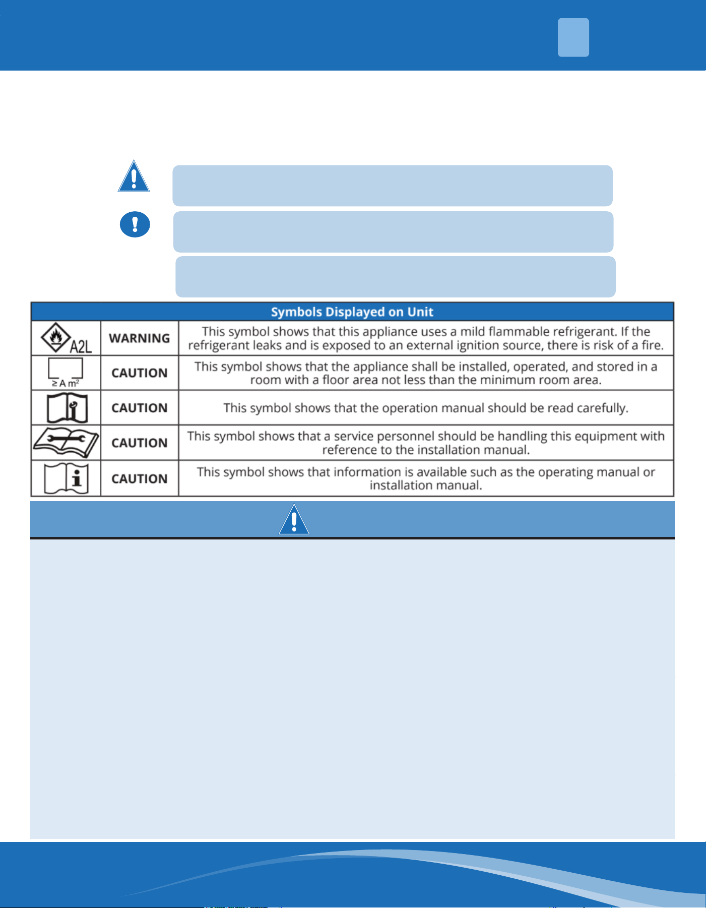
mrcool.com 2
2
Safety Precautions
Read Before Using
WARNING
• These instructions are intended as an aid to qualied licensed service personnel for proper installation,
adjustment and operation of this unit. Read these instructions thoroughly before attempting installation or
operation.
• Failure to follow these instructions may result in improper installation, adjustment, service or maintenance
possibly resulting in re, electrical shock, property damage, personal injury, or death.
• MRCOOL® warranty does not cover any damage or defect to the unit caused by the attachment or use
of any components, accessories, or devices (other than those authorized by MRCOOL®) into, onto or in
conjunction with the unit. You should be aware that the use of unauthorized components, accessories or
devices may adversely aect the operation of the heat pump and may also endanger life and property.
MRCOOL® disclaimer any responsibility for such loss or injury resulting from the use of such unauthorized
components, accessories, or devices.
• Disconnect all power to the unit before installing or servicing. Failure to do so can result in severe electrical
shock or death.
• Do not, under any circumstances, connect return ductwork to any other heat producing device such
as a replace insert, stove, etc. Unauthorized use of such devices may result in re, carbon monoxide
poisoning, explosion, property damage, severe personal injury, or death.
• The unit must be permanently grounded. A grounding lug is provided. Failure to ground this unit can result
in re or electrical shock causing property damage, severe personal injury, or death.
• Only electric heater kits supplied by this manufacturer as described in this publication have been designed,
tested and evaluated by a nationally recognized safety testing agency for use with this unit. Use of any
other MRCOOL® electric heaters installed within this unit may cause hazardous conditions resulting in
property damage, re, bodily injury, or death.
SAFETY
1
CAUTION
Indicates the most serious hazard which will result in severe
personal injury, property and/or product damage, or death.
Indicates hazards which could result in moderate personal injury
and/or property and product damage.
WARNING
NOTE
Indicates suggestions which will result in enhanced
installation, relaibility, or operation
Incorrect usage may cause serious damage or injury. The symbols below are used throughout this manual to
indicate instructions that should be followed closely or actions that should be avoided to prevent death, injury,
and/or property damage.
mrcool.com3
WARNING: PROPOSITION 65
This appliance contains berglass insulation. Respirable particles of berglass are known to the state of
California to cause cancer.
SAFETY
1
• The rst 36 inches of supply air plenum and ductwork must be constructed of sheet metal as required by
NFPA 90B. The supply air plenum or duct must have a solid sheet metal bottom directly under the unit
with no openings, registers, or exible air ducts located in it. If exible supply air ducts are used they may
be located only in the vertical walls of rectangular plenum, a minimum of 6 inches from the solid bottom.
Metal plenum of duct may be connected to the combustible oor base, if not, it must be connected to the
unit supply duct exposed to the supply air opening from the downow unit. Exposing combustible (non-
metal) material to the supply opening of a down-ow unit can cause a re resulting in property damage,
personal injury or death. Exception warning to downow: Installations on concrete oor slab with supply
air plenum and ductwork completely encased must be not less than 2 inches of concrete (See NFPA 90A).
• Only use this unit in a well-ventilated area and ensure unit's airow inlet and outlet would not be impeded
by obstructions.
• Do not use this unit in the following locations:
• Locations with mineral oil.
• Locations with saline atmospheres, such as seaside locations.
• Locations with sulfurous atmospheres, such as near natural hot springs.
• Where high-voltage electricity is present, like in certain industrial locations.
• On vehicles or vessels, such as trucks or ferry boats.
• Where exposure to oily or very humid air may occur, like kitchens.
• In proximity to sources of electromagnetic radiation, such as high-frequency transmitters or other high
strength radiation devices.
• Do not attempt to accelerate the defrosting process to clean, unless utilizing procedures recommended
by MRCOOL®.
• The appliance shall be stored in a room that does not have a continuously operating ignition sources
(for example: open ames, an operating gas appliance or an operating electric heater).
• Do not pierce or burn the unit. Be aware that refrigerants may not contain an odor.
• If refrigerant gas leaks during installation, ventilate the area immediately.
• Comply with national gas regulations.
When repairing the refrigerating system, comply with the following precautions prior to conducting work on
the system:
• Work must be undertaken according to controlled procedures to minimize the risk of the presence of
ammable gases or vapors while the work is being performed.
• All maintenance sta and others working in the local area should be instructed on the nature of work
being carried out. Work in conned spaces shall be avoided.
• The area shall be checked with an appropriate refrigerant detector prior to and during work, to ensure
the technician is aware of potentially toxic or ammable environment. Ensure the leak detection
equipment being used is suitable for use with all applicable refrigerants, i.e., non-sparking, adequately
sealed or intrinsically safe.
• If any hot work is to be conducted on the refrigerating equipment or any associated parts, appropriate
re extinguishing equipment shall be available and easily accessible. Have a dry powder or CO2 re
extinguisher adjacent to the charging area.
• When carrying out work in relation to a refrigerating system that involves exposing any pipe work, no
sources of ignition should be used in such a manner that it may lead to the risk of re or explosion. All
possible ignition sources, including cigarette smoking , should be kept suciently far away from the
site of installation, repair, or removal and disposal of the unit, during which refrigerant can possibly
be released into the surrounding space. Prior to beginning work, the area around the equipment is to
be surveyed to ensure there are no ammable hazards or ignition risks. “No Smoking” signs must be
clearly displayed.
• This appliance is not intended for use by people (including children) with reduced physical, sensory or
mental capabilities, or people who lack experience and knowledge, unless they are supervised or have
been given instructions concerning the use of the appliance by a person responsible for their safety.
GENERAL WARNINGS FOR SAFETY

mrcool.com 4
4
GENERAL WARNINGS FOR SAFETY CONT.
• Children should be supervised to ensure that they do not play with the appliance.
• Any person who is involved with working on or opening a refrigerant circuit should hold a current valid
certicate from an industry-accredited assessment authority, which authorizes their competence to
handle refrigerants safely.
• Servicing shall only be performed as recommended by MRCOOL®.
• Maintenance and repair requiring the assistance of other skilled personnel should be carried out under
the supervision of a person competent in the use of ammable refrigerants.
• Prior to beginning work on systems containing ammable refrigerants, safety checks are necessary to
minimize the risk of ignition.
• Ensure the area is in the open or that it is adequately ventilated before opening the system or
conducting any hot work. A degree of ventilation should continue during the duration of the work. The
ventilation should safely disperse any released refrigerant and preferably expel it externally into the
surroundings.
• Where electrical components are being changed, they must be t according to their purpose and to
the correct specication. At all times the manufacturer’s maintenance and service guidelines shall be
followed. If in doubt, consult the MRCOOL® Customer Service team for assistance. The following checks
shall be applied to installations using ammable refrigerants:
• The actual refrigerant charge is in accordance with the room size within which the refrigerant-
containing parts are installed.
• The ventilation machinery and outlets are operating adequately and are not obstructed.
• If an indirect refrigerating circuit is being used, the secondary circuit need to be checked for the
presence of refrigerant.
• Equipment marking must remain visible and legible. Markings and signs that are illegible must be
corrected.
• Refrigerating pipe or components are installed in a position where they are unlikely to be exposed to
any substances which may corrode refrigerant-containing components, unless the components are
constructed of materials that are inherently resistant to corrosion or are suitably protected against
corrosion.
Repair and maintenance of electrical components should include initial safety checks and component
inspection procedures. If a fault exists that could compromise safety, the no electrical supply shall be
connected to the circuit until the fault has been dealt with:
• That there is continuity of grounding.
• That capacitors are discharged. This should be done in a safe manner to avoid the possibility of
sparking.
• That no live electrical components and wiring are exposed while charging, recovering, or purging the
system.
• Flammable refrigerant-
• Sealed electrical components shall be replaced.
• Intrinsically safe components must be replaced.
• Check that cabling will not be subject to wear, corrosion, excessive pressure, vibration, sharp edges or
any other adverse environmental eects. The check shall also take into account the eects of aging or
continual vibration from sources such as compressors or fans.
• Under no circumstances shall potential sources of ignition be used while searching for or detection of
refrigerant leaks. A halide torch (or any other detector using a naked ame) shall not be used.
• Electronic leak detectors may be used to detect refrigerant leaks but, in the case of ammable
refrigerants, the sensitivity may not be adequate, or may need recalibration. (Detection equipment shall
be calibrated in a refrigerant-free area.)
• Ensure that the detector is not a potential source of ignition and is suitable for the refrigerant used.
Leak detection equipment shall be set at a percentage of the LFL of the refrigerant and should be
calibrated for the refrigerant employed, and the appropriate percentage of gas (25% maximum) is
conrmed.
• If a leak is suspected, all naked ames should be removed or extinguished.
• If a leakage of refrigerant which requires brazing is found, all of the refrigerant shall be recovered from
the system, or isolated (by means of shut o valves) in a part of the system remote from the leak.
SAFETY
1

mrcool.com5
GENERAL WARNINGS FOR SAFETY CONT.
• Leak detection uids are also suitable for use with most refrigerants but the use of detergents
containing chlorine should be avoided as the chlorine may react with the refrigerant and corrode the
copper pipe-work.
• Examples of leak detection uids are, the bubble method.
• When breaking into the refrigerant circuit to make repairs or for any other purpose, conventional
procedures should be used.
• However, for ammable refrigerants it is important that best practice be followed, since ammability is
a consideration.
The following procedure shall be adhered to:
1. Safely remove refrigerant following local and national regulations.
2. Evacuate.
3. Purge the circuit with inert gas.
4. Evacuate.
5. Continuously ush or purge with inert gas when using ame to open circuit.
6. Open the circuit.
• The refrigerant charge shall be recovered into the correct recovery cylinders if venting is not allowed by
local and national codes. For appliances containing ammable refrigerants, the system should be purged
with oxygen-free nitrogen to render the appliance safe for ammable refrigerants. This process might need
to be repeated several times. Compressed air or oxygen shall not be used for purging refrigerant systems.
• For appliances containing ammable refrigerants, refrigerant purging should be achieved by breaking
the vacuum in the system with oxygen-free nitrogen and continuing to ll until the working pressure
is achieved, then venting to atmosphere, and nally pulling down to a vacuum. This process must be
repeated until no refrigerant is within the system. When the nal oxygen-free nitrogen charge is used, the
system should be vented down to atmospheric pressure to enable work to take place.
• The outlet for the vacuum pump shall not be close to any potential ignition sources, and ventilation should
be available.
• Ensure contamination of dierent refrigerants does not occur when using charging equipment. Hoses or
lines shall be as short as possible to minimize the amount of refrigerant they contain.
• Cylinders shall be kept upright.
• Ensure that the refrigeration system is grounded prior to charging the system with refrigerant.
• Label the system when charging is complete (if it is not already labeled).
• Take extreme care not to overll the refrigeration system.
• Prior to recharging the system, it shall be pressure-tested with the appropriate purging gas. The system
shall be leak-tested on completion of charging but prior to commissioning. A follow-up leak test should be
carried out prior to leaving the site.
• Before carrying out this procedure, it is essential that the technician is completely familiar with the
equipment and all its detail. It is recommended that all refrigerants are recovered safely. Prior to the task
being carried out, an oil and refrigerant sample shall be taken in case analysis is required prior to reuse of
reclaimed refrigerant. It is essential that electrical power is available before the task is commenced.
• Isolate system electrically.
• Become familiar with the equipment and its operation.
Before attempting the procedure ensure that:
1. Mechanical handling equipment is available, if required, for handling refrigerant cylinders;
2. All personal protective equipment is available and used correctly;
3. The recovery process is supervised at all times by a competent person;
4. Recovery equipment and cylinders conform to the appropriate standards.
• Pump down refrigerant system, if possible.
• If a vacuum is not possible, make a manifold so that refrigerant can be removed from various parts of the
system.
• Make sure the cylinder is situated on the scales before recovery takes place.
• Start the recovery machine and operate it in accordance with the manufacturer's instructions.
• Do not overll cylinders. (No more than 80% volume liquid charge).
• Do not exceed the maximum working pressure of the cylinder, even temporarily.
SAFETY
1
mrcool.com 6
6
GENERAL WARNINGS FOR SAFETY CONT.
• When the cylinders have been lled correctly and the process has been completed, make sure that the
cylinders and the equipment are removed from site promptly and all isolation valves on the equipment
are closed o. Recovered refrigerant should not be charged into another refrigeration system unless it
has been cleaned and checked. Equipment shall be labeled stating that it has been decommissioned and
emptied of refrigerant. The label shall be dated and signed.
• Ensure that there are labels on the equipment stating that the equipment contains ammable refrigerant.
• When removing refrigerant from a system, either for servicing or decommissioning, it is recommended
that all refrigerants are removed safely. When transferring refrigerant into cylinders, ensure that only
appropriate refrigerant recovery cylinders are employed. Ensure that the correct number of cylinders
for holding the total system charge is available. All cylinders to be used are designated for the recovered
refrigerant and labeled for that refrigerant (i.e. special cylinders for the recovery of refrigerant). Cylinders
should be complete with pressure-relief valve and associated shut-o valves in good working order. Empty
recovery cylinders are evacuated and, if possible, cooled before recovery occurs.
• The recovery equipment must be in good working order and come with a set of instructions for proper
usage. Furthermore, the equipment should be suitable for safely recovering ammable refrigerants. If in
doubt, the manufacturer should be consulted. In addition, a set of calibrated weighing scales should be
available and in good working order. Hoses need to be complete with leak-free disconnect couplings and in
good condition.
• The recovered refrigerant shall be processed according to local legislation in the correct recovery cylinder,
and the relevant waste transfer note arranged. Do not mix refrigerants in recovery units and especially not
in cylinders.
• If compressors or compressor oils are to be removed, ensure they have been evacuated to an acceptable
level to be certain that ammable refrigerant does not remain within the lubricant. The compressor body
shall not be heated by an open ame or other ignition sources to accelerate this process. When oil is
drained from a system, it shall be carried out safely.
• Do not use the air conditioner for other purposes. In order to avoid any quality deterioration. do not use
the unit for the cooling of precision instruments, food, plants, animals, or works of art. Before cleaning, be
sure to stop the operation, turn the breaker o and unplug the supply cord. Otherwise, electric shock and
injury may occur.
• In order to avoid electric shock or re, make sure a ground leak detector is installed.
• Never touch the air outlet or the horizontal blades while the swing ap is in operation. Your ngers may be
come caught or the unit may break down.
• Never put any objects into the air inlet or outlet.
• Objects touching the fan at high speed can be dangerous.
• Never inspect or service the unit by yourself.
• Ask a qualied service person to perform this task.
• If electrical appliances are disposed of in landlls or dumps, hazardous substances can leak into the
groundwater and get into the food chain, harming your health and well-being.
• Do not dispose of this product as unsorted municipal waste. This waste should be collected separately
for special treatment. Do not dispose of electrical appliances as unsorted municipal waste. Use separate
collection facilities. Contact your local government agency for information regarding the connection
systems available.
• To prevent refrigerant leak, contact your local dealer or the MRCOOL® Customer Service team.
• When the system is installed and operated in a small room, it is required to maintain the concentration
of the refrigerant below the limit, in case a leak occurs. Otherwise, oxygen in the room may be aected,
resulting in a serious accident.
• The refrigerant in the air conditioner is safe and normally does not leak.
• If the refrigerant leaks into the room and comes into contact with the re of a burner, a heater or a cooker,
a harmful gas could be released.
• Turn o any combustible heating devices, ventilate the room, and contact the dealer from whom you
purchased the unit.
• Do not use the air conditioner until a service person conrms the refrigerant leak is repaired.
• Keep ventilation openings clear of obstruction.This unit uses R454B refrigerant.
SAFETY
1
mrcool.com7
SAFETY
1
CAUTION
• Be sure the air conditioner is grounded.
• In order to avoid electric shock, make sure the unit is grounded and that the ground wire is not connected
to a gas or water pipe, lightning conductor or telephone ground wire.
• Do not operate the air conditioner with wet hands. An electric shock may happen.
• Do not touch the heat exchanger ns. These ns are sharp and could cut you.
• To avoid oxygen deciency, ventilate the room suciently if equipment with a burner is used together with
the air conditioner.
• Arrange the drain hose to ensure smooth drainage. Incomplete drainage may cause wetting of the
building, furniture, etc.
• Never touch the internal parts of the controller.
• Do not remove the blower access panel. Some parts inside are dangerous to touch, and machine issues
may occur.
• Attention is drawn to the fact that additional transportation regulations may exist with respect to
the equipment containing a ammable gas. The maximum number of pieces of equipment or the
conguration of the equipment permitted to be transported together will be determined by the applicable
transport regulations.
• Signs for similar appliances used in a work area are generally addressed by local regulations and give the
minimum requirements for the provision of safety and/or health signs for a work location.
• All required signs are to be maintained and employers should ensure employees receive suitable and
sucient instruction and training on the meaning of appropriate safety signs and the actions that need to
be taken in connection with these signs.
• The eectiveness of signs should not be diminished by too many signs being placed together.
• Any pictograms used should be as simple as possible and contain only essential details.
• The storage of the appliance should be in accordance with the applicable regulations or instructions,
whichever is more stringent.
• Storage package protection should be constructed such a way that mechanical damage to the equipment
inside the package will not cause a leak of the refrigerant charge.
• The maximum number of pieces of equipment permitted to be stored together will be determined by local
regulations.
• Do not operate the air conditioner when using a room fumigation - type insecticide. Failure to observe this
precaution could cause the chemicals to become deposited in the unit, which could endanger the health of
those who are hypersensitive to chemicals. It may also cause the refrigerant sensor to alarm.
• Do not place appliances which produce open ames in places exposed to the airow from the unit or
under the indoor unit. It may cause incomplete combustion or deformation of the unit due to the heat.
• Do not install the air conditioner in a location where ammable gas may leak out. If the gas leaks out and
stays around the air conditioner, a re may break out.
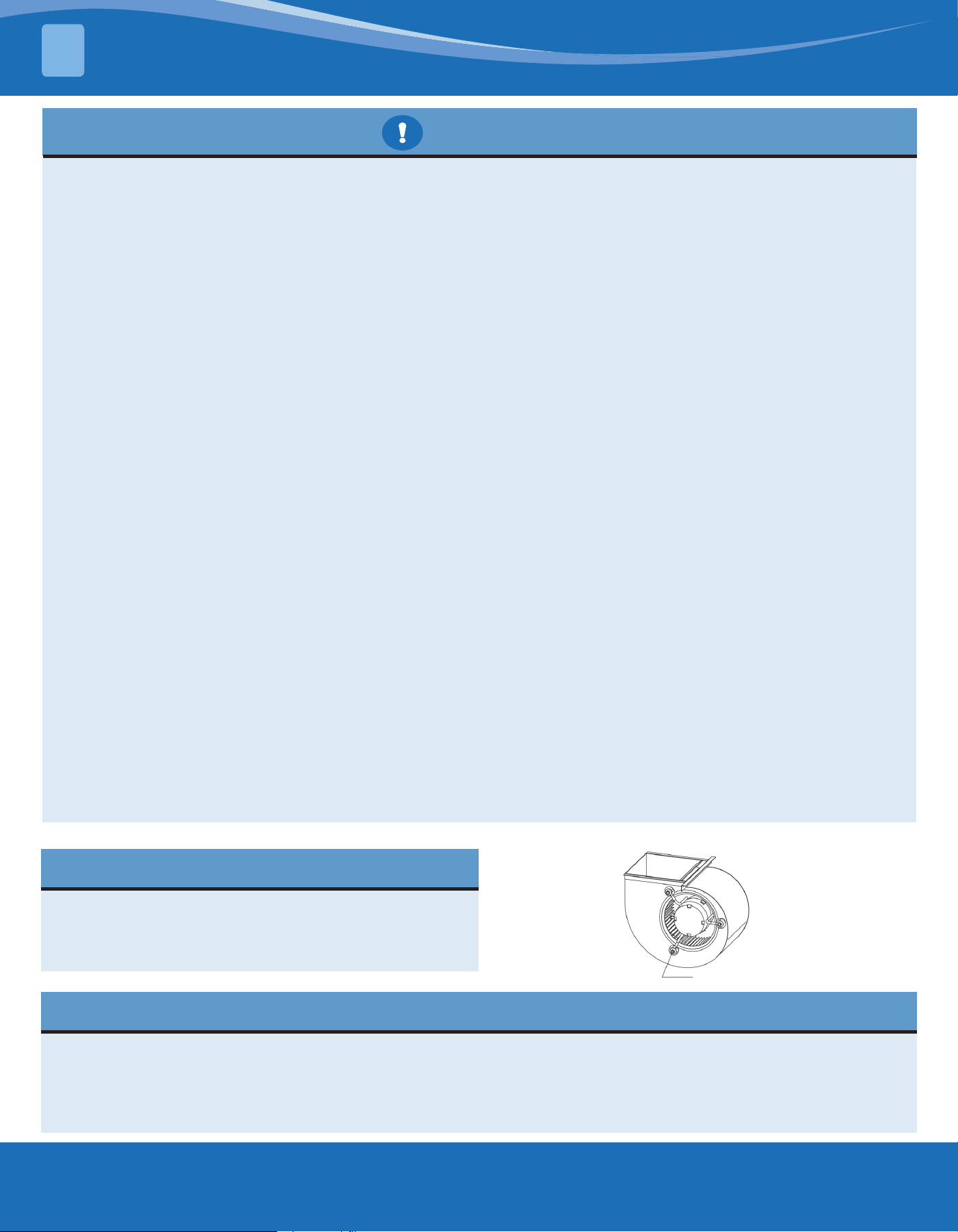
NOTE
Make sure the blower motor support is tight (3-motor
mount bolts) then check to see if the wheel is secured
to motor shaft before operating the unit, as indicated
in the gure to the right.
Blower Motor Shipping Bolt
Checking Motor Fix Status:
DISPOSAL
Comply with national regulations. Components and accessories from the units are not part of ordinary
domestic waste. Complete units, compressors, motors, etc. are only to be disposed of via qualifed disposal
specialists. This unit uses ammable refrigerant R454B Please contact the dealer when you want to dispose
of this unit. Law requires that thecollection,transportealion and disposal of rerigerants must conrm with the
regulations governing the colleclion and destruction of hydrouorocarbons.
Contents
mrcool.com 8
2.1 Nomenclature
UNIT OVERVIEW
2
Product Category
Application
A=Upow/Downow
U=Upow
D=Downow
M=Multi-Position
C=Ceiling Mounted
W=Wall-Mounted
A=Air Handler
Cabinet Finish
U=Uncased
P=Cased-Painted
C=Cased-Painted
Motor
S=Single Speed
T=Multi Speed
E=ECM
V=Inverter
MCAE
MCAE A A U S E
06 A 1 1
A
A
A
A
Revision
Series
Electrical
1=208/230 V, 1Phase, 60 Hz
Refrigerant
1=R410A
2=R454B
3=R32
Cabinet Width
A=14.5"
B=17.5"
C=19.3"
D=21"
E=22"
F=24.5"
Nominal Capacity
06=0.5 Tons
09=0.75 Tons
12=1 Ton
18=1.5 Tons
24=2 Tons
30=2.5 Tons
36=3 Tons
42=3.5 Tons
48=4 Tons
60=5 Tons
Expansion Device
E=Electronic Expansion Valve
F=Flowrater
T=TXV
MRCOOL®
mrcool.com9
UNIT OVERVIEW
2
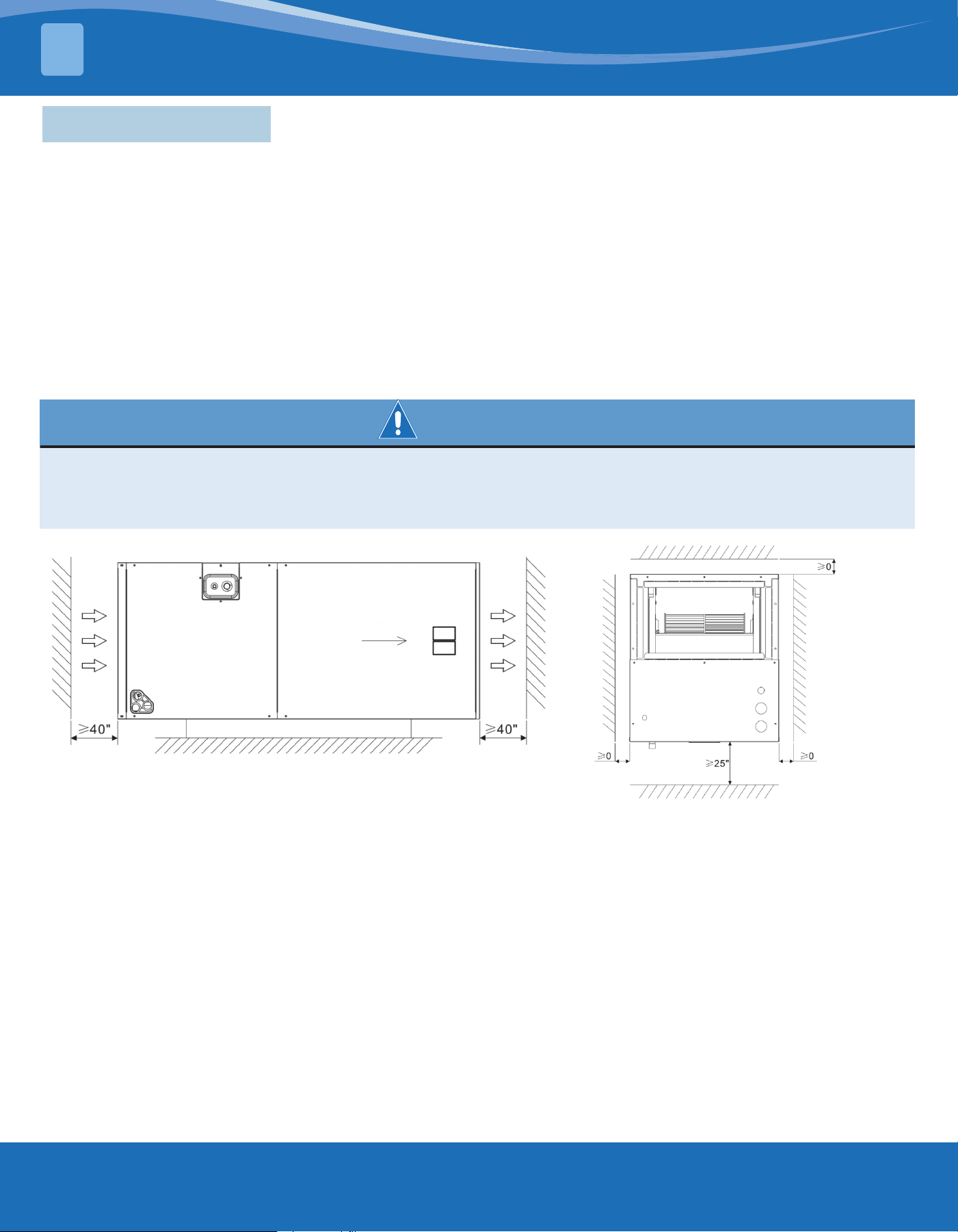
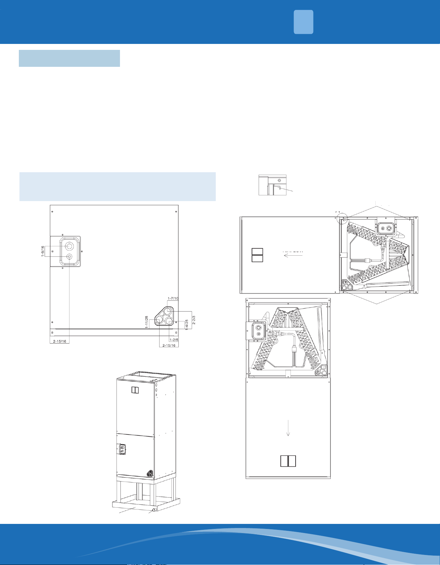
Figure 2-1 Clearances in the Horizontal Position
AIRFLOW
Figure 2-2 Clearances in the
Vertical Position
Front of unit
Installation in Hot/Humid Areas:
• If the humidity inside the installation space might exceed 86°F (30°C) and RH 80%, it is recommended to
insulate the cabinet exterior.
• Use glass wool or polyethylene foam as insulation so the thickness is more than 2in (5.08cm) and ts inside
the installation space opening. Otherwise, condensation may form on the surface of the insulation.
• Be sure to use insulation designed for use with HVAC systems. Condensation may form on the product
during cool operation. It is also recommended to use a second drain pan and secure the unit rmly to
prevent it from falling.
WARNING
• DO NOT install unit in an area where ammable materials are present due to the risk of an explosion
resulting in serious injury or death.
• If the supporting structural members are not strong enough to take the unit's weight, the unit could fall out
of place and cause serious injury.
• The unit can be positioned for vertical upow,
downow, or horizontal air distribution. The direct-
drive motor distributes air volume to match any
application. The 3-speed motor allots airow to
meet standard service.
• An access panel for power and control wiring at the
top and side of the unit makes the screw terminal
more easily reachable.
• If a return air duct is not installed, carefully select
the location and method of product installation so
airow into the unit will not be blocked.
• The unit should be installed in a level position to
ensure proper condensation drainage. Up to an
additional 1/4" rise over the width or depth of
the unit is allowed to create additional sloping
toward the drain. Unit must be positioned between
level and 1/4" rise, sloping toward the drain
connections.
• Install the indoor and outdoor unit, power
supply wiring, and connecting wires at least 3.5ft
(1.0668m) away from televisions or radios in order
to prevent image interference or noise. To ensure
proper installation, select a solid and level site.
Ensure enough space maintained for installation
and maintenance. See Figures 2-1 and 2-2.
2.2 Unit Information
mrcool.com 10
10
2.3 Unit Dimensions
Model Size
Dimensions in. [mm]
Unit Height
"H" in (mm)
Unit Width
"W" in (mm)
Unit Length
"D" in (mm)
Supply Duct
"A" in (mm)
Liquid Line/
Vapor Line in.
18K 45.75" [1162] 19.625" [500] 22" [560] 17.875" [454] 0.375"/ 0.75"
24K 45.75" [1162] 19.625" [500] 22" [560] 17.875" [454] 0.375"/ 0.75"
30K 45.75" [1162] 19.625" [500] 22" [560] 17.875" [454] 0.375"/ 0.75"
36K 45.75" [1162] 19.625" [500] 22" [560] 17.875" [454] 0.375"/ 0.75"
42K 45.75" [1162] 19.625" [500] 22" [560] 17.875" [454] 0.375"/ 0.75"
48K 53.125" [1350] 22" [560] 24.5" [623] 19.5" [496] 0.375"/ 0.875"
60K 53.125" [1350] 22" [560] 24.5" [623] 19.5" [496] 0.375"/ 0.875"
Primary Drain Connection 3/4"
Female pipe thread (NPT)
High Voltage Connection
Low Voltage Connection
Vapor Line Connection Copper (Sweat)
Liquid Line Connection Copper (Sweat)
Auxiliary Drain Connection 3/4"
Female pipe thread (NPT)
Note: 25" clearance is required in the front of
the unit for lter and coil maintenance
Electrical connections may exit out the top
or either side.
Upow unit shown; Unit may be installed
to accommodate upow, downow, and
horizontal (left or right) air supply.
Primary Drain Connection 3/4"
Female pipe thread (NPT)
AIR
SUPPLY
UNIT OVERVIEW
2
Figure 2-3
mrcool.com11
UNIT OVERVIEW
2
2.4 Parts Introduction
Number 1 2 3 4 5
Parts Control Board AC Motor Blower AL-Evaporator R454B Refrigerant Sensor
Figure 2-4
mrcool.com 12
12
3.1 Unit Orientation
Vertical Upow
• Vertical upow conguration is the standard
orientation for all factory models, indicated in Figure
3-1.
• If a side-return air opening is required, eld
fabricates a return air plenum with an opening large
enough to supply unit and strong enough to support
unit weight.
• If return air is to be ducted, install duct ush with
the oor. Use reproof resilient gasket 1/8"-1/4" in.
thick between the ducts (unit and oor). Set unit on
oor over opening.
NOTE:
Torque applied to drain connections should not
exceed 15 ft/lbs.
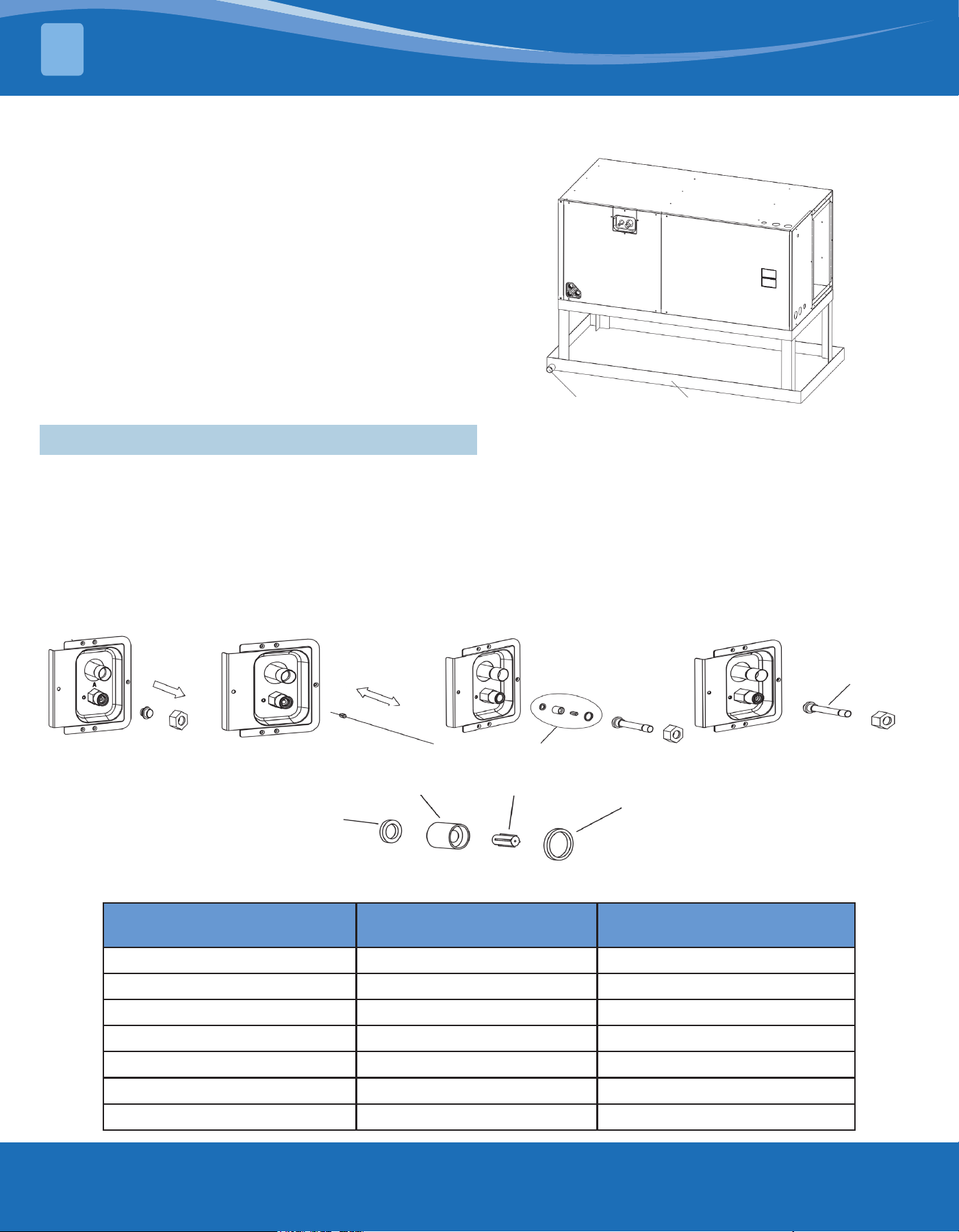
Figure 3-1 Dimensions for Front-Connect Coil
Vertical Downow
Conversion to Vertical Downow:
A vertical upow unit may be converted to vertical
downow. See Figure 3-2.
1. Remove the coil access panel.
2. Remove the refrigerant leak detection sensor and
indoor coil.
3. Reinstall the indoor coil 180° from the original
position.
4. Reinstall the refrigerant sensor at the location
shown in Figure 3-3.
Ensure the retaining
channel is fully engaged
with the coil ray.
Rails
Rails
A
A
Rails
AIRFLOW
AIRFLOW
Figure 3-2 Vertical Downow &
Horizontal Left Airow
Second Drain Pan
Drain Piping
Installed Vertically:
INSTALLATION
3
mrcool.com13
INSTALLATION
3
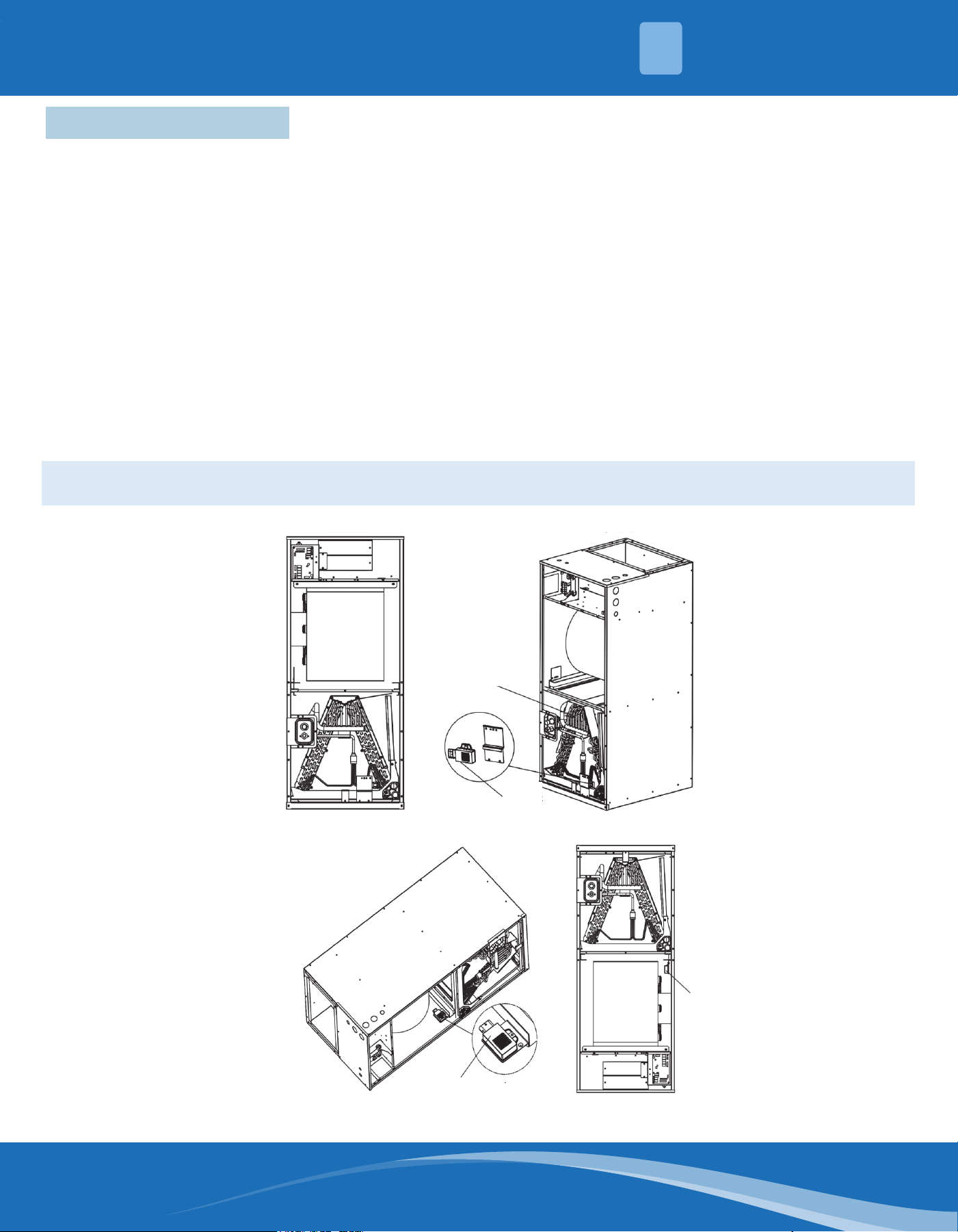
3.2 Coil Piston Replacement and Installation
1. Use a wrench to loosen the nut and pull out the rubber plug.
2. Replacement installation method of valve core.
3. Take out the inner O-ring, piston sleeve, piston, outer O-ring, liquid line connection from the accessories, and
install them in sequence. Ensure the direction is correct. The inner O-ring is installed together with the piston
sleeve.
4. Re-attach the liquid line with the nut and tighten it up to 1/6th turn past hand-tightened.
Inner O-Ring
Piston Sleeve Piston
Outer O-Ring
Replace
Install
1.
2.
Liquid Line
Connection
A
3.
4.
Condensing Unit Nom.
Cooling (BTUH)
(Orice) Piston Model (Orice) Piston Size (mm)
18,000 054 1.3716
24,000 054 1.3716
30,000 060 1.524
36,000 066 1.6764
42,000 076 1.9304
48,000 082 2.0828
60,000 092 2.3368
Horizontal Airow
Horizontal right is the default factory conguration
for the units. Horizontal left isn't the default factory
conguration for the units. Conversion to horizontal
left: A vertical upow unit may be converted to
horizontal left by removing the indoor coil assembly and
reinstalling the coil as shown for lefthand air supply.
1. Rotate unit into the downow position with the coil
compartment on top and the blower compartment
on the bottom. See Figure 3-2.
2. Reinstall the indoor coil 180° from the original
position. Ensure the retaining channel is fully
engaged with the coil rail. See Figure 3-2.
3. Secondary drain pan kits are recommended when
the unit is congured for the horizontal position
over a nished ceiling and/or a living space.
Second Drain PanDrain Piping
Installed Horizontally:
mrcool.com 14
14
3.3 Refrigerant Sensor
R454B refrigerant leakage sensor is congured for the indoor unit. To meet dierent installation scenarios,
the refrigerant sensor has two installation positions. The factory set of the refrigerant sensor is applied to
the vertical upow and horizontal right applications. The refrigerant sensor needs to be relocated for vertical
downow and horizontal left. Before installing the indoor unit, check whether the refrigerant sensor is correctly
installed according to Figure 3-3.
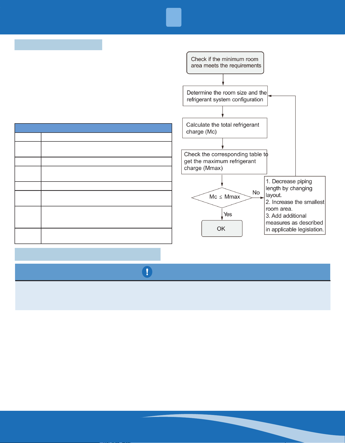
Steps for Changing Cabinet Orientation for Refrigerant Sensor:
1. Remove the screws, upper side plate, lower side plate, lter cover plate, and support strip. Disconnect the
refrigerant sensor on the control board. See Figure 3-3, step 1.
2. Cut o the zipper buckle of the refrigerant leakage sensor harness, and then unscrew the screws from the
support strip and the refrigerant leakage sensor mounting plate to remove the sensor. See Figure 3-3, step 2.
3. Reinstall the indoor coil 180° from its original position and install the refrigerant leakage sensor in the
position shown in Figure 3-3, step 3.
4. Replace the wiring harness in the correct position and secure it in place. Insert the refrigerant sensor cable
back into the control board. See Figure 3-3, step 3.
5. Reinstall the upper side panel and other components, and x them with screws.
STEP 1 STEP 2
STEP 3
Indoor
Coil
Assembly
R454B
refrigerant
sensor
R454B
refrigerant
sensor
R454B refrigerant sensor
Figure 3-3 Vertical downow & horizontal left applications conversion
NOTE:
The refrigerant detection sensor needs to be relocated in this application. Please follow subsequent steps.
INSTALLATION
3

mrcool.com15
INSTALLATION
3
The R454B refrigerant leakage sensor is congured for the indoor unit. The fan operation can be initiated by
the R454B refrigerant sensor, ensuring that it meets the required circulation airow requirements. The allowed
maximum refrigerant charge (Mmax) and the required minimum room area (Amin) can be determined according
to Table 4-1 and Table 4-2.
3.4 Refrigerant Connections
• Keep the coil connections sealed until refrigerant connections are made. See the installation instructions for
the outdoor unit for details on line sizing, tubing installation, and charging information.
• Coil is shipped without charge. Evacuate the system before charging with refrigerant.
• Install refrigerant tubing so that it does not block service access to the front of the unit.
• Nitrogen should ow through the refrigerant lines while brazing.
• Use a brazing shield to protect the cabinet’s paint and a wet rag to protect the rubber grommet from being
damaged by torch ames. After the refrigerant connections are made, seal the gap around the connections
with pressure sensitive gasket.
WARNING
• The refrigerant leakage sensor can only use the factory model of the specied model indicated in the
corresponding manual.
• The R454B refrigerant leakage sensor must be used to activate the refrigerant shuto device, the alarm
device, incorporated circulation airow or other emergency controls, which should give an electrical signal
at a predetermined alarm set point in response to leaked refrigerant.
• The location of leakage sensors shall be chosen in relation to the dierent installation scenarios.
• The installation of the refrigerant leakage sensor shall allow access for checking, repair or replacement by
an authorized person.
• The refrigerant leakage sensor shall be installed so its function can be veried easily.
• The refrigerant leakage sensor shall be protected to prevent tampering or unauthorized resetting of the
pre-set value.
• To be eective, the refrigerant leakage sensor must be electrically powered at all times after installation,
other than when servicing.
• If the refrigerant leakage sensor detects a refrigerant leak, the fan will keep running, the compressor
will stop, and electric heater will be shut o. You should immediately leave the leak area and notify a
professional for handling.
• The system will return to normal operation when refrigerant is no longer detected in 5 minutes.
• The service life of the refrigerant sensor is 15 years, and it should be replaced after the service life.
• To ensure the detection accuracy of the refrigerant sensor, it is recommended to blow dust o the surface
of the refrigerant sensor after it is used for a long time.
• Leak Detection System installed on the indoor unit. The unit must be powered on except during servicing.
• Ensure the apparatus is mounted securely.
• These instructions are exclusively intended for qualied contractors and authorized installers.
• Work on the refrigerant circuit with ammable refrigerant in safety group A2L may only be carried out
by authorized contractors. These heating contractors must be trained in accordance with UL 60335-2-40,
Section HH. The certicate of competence from an industry accredited body is required.
• Work on electrical equipment may only be carried out by a qualied electrician.
• Before initial commissioning, all safety – related points must be checked by the particular certied heating
contractors. The system must be commissioned by the system installer or a qualied person authorized by
the installer.
• For installation of the indoor unit, refer to the corresponding installation and operation manual. If an
indoor unit is installed in an unventilated area, the area shall be so constructed that should any refrigerant
leak, it will not stagnate so as to create a re or explosion hazard.
• The appliance shall be stored so as to prevent mechanical damage from occurring.
• Do not stack combustible materials on the surface of the indoor unit.
mrcool.com 16
16
4.1 Refrigerant Charge
In UL/CSA 60335-2-40, R454B refrigerant is classied as
class A2L, which is mildly ammable. Therefore, R454B
refrigerant is suitable for systems needing additional
refrigerant charge and which will limit the area of the
rooms being served by the system.
Similarly, the total amount of refrigerant in the system
should be less than or equal to the allowable maximum
refrigerant charge. The allowable maximum refrigerant
charge depends on the area of the rooms being served
by the system.
Area Formula
Mc The actual refrigerant charge in the system.
A
The actual room area where the appliance is
installed.
Amin The required minimum room area.
Mmax
The allowable maximum refrigerant charge
in a room.
Qmin The minimum circulation airow.
Anvmin
The minimum opening area for connected
rooms.
TAmin
The total area of the conditioned space (for
appliances serving one or more rooms with
an air duct system).
TA
The total area of the conditioned space
connected by air ducts.
Installation scheme ow chart
4.2 Room Area Calculation Requirements
CAUTION
• The space considered should be any space which contains refrigerant-containing parts or, into where,
refrigerant could be released.
• The room area (A) of the smallest, enclosed, occupied space should be used in the determination of the
refrigerant quantity limits.
For determination of room area (A) when used to calculate the refrigerant charge limit, the following should
apply:
• The room area (A) should be dened as the room area enclosed by the projection to the base of the walls,
partitions, and doors of the space where the appliance is installed.
• Spaces connected by only drop ceilings, ductwork, or similar connections should not be considered a single
space.
Units mounted higher than 70.85in (175.61cm) and spaces divided by partition walls that are no higher than
62.98in (157.48cm) should be considered a single space. Rooms on the same oor and connected by an open
passageway between the spaces can be considered a single room when determining compliance to Amin, if the
passageway complies with all of the following:
• It is a permanent opening.
• It extends to the oor.
• It is intended for people to walk through.
ROOM AREA LIMITATIONS
4
mrcool.com17
The area of the connected rooms, on the same oor,
connected by a permanent opening in the walls and/
or doors between occupied spaces, including gaps
between the wall and the oor can be considered a
single room when determining compliance to Amin,
provided all the following conditions are met.
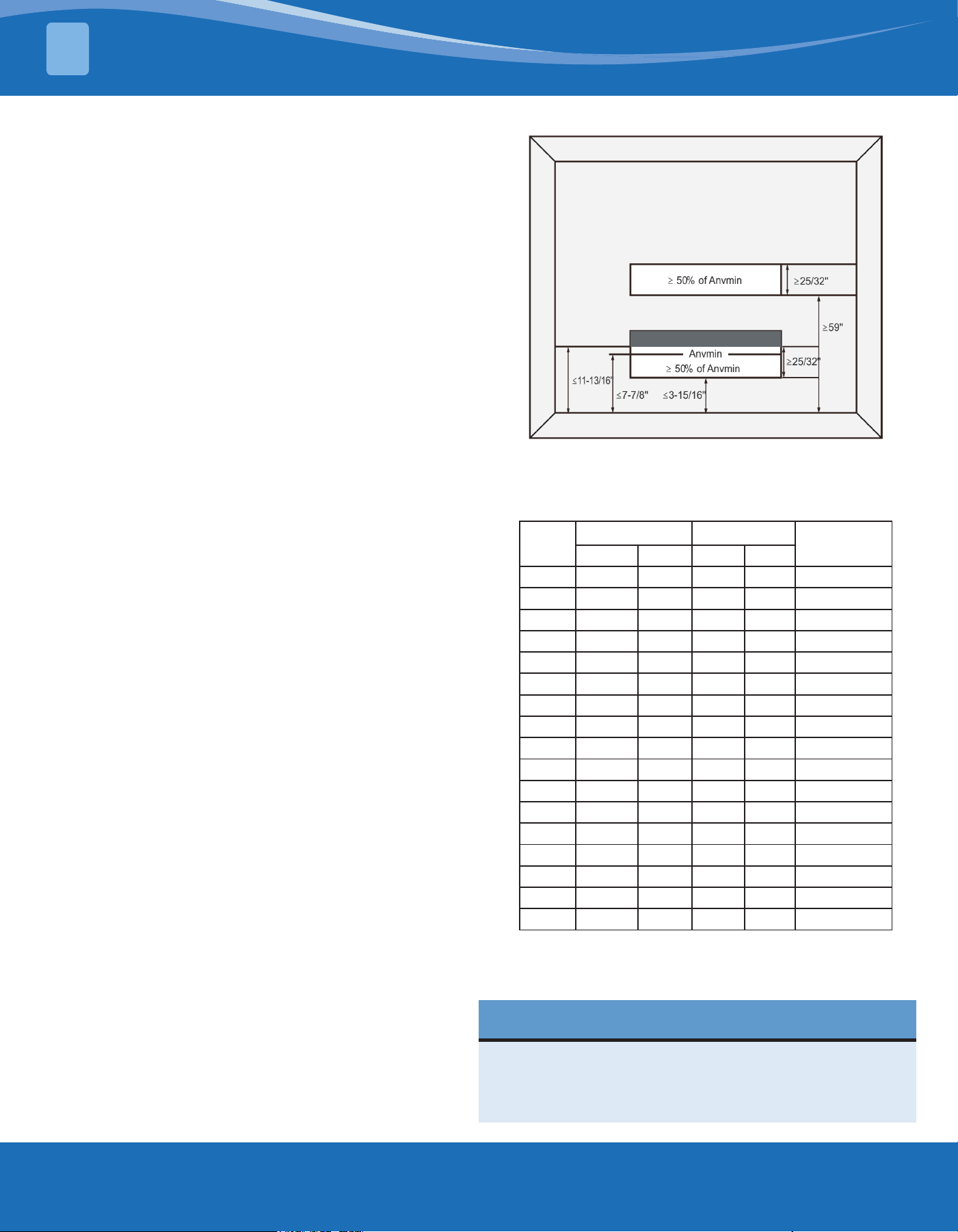
Low Level Opening:
1. The opening should not be less than Anvmin in
Figure 4-1.
2. The area of any openings above 11.8125in (27.94cm)
from the oor should not be considered in
determining compliance with Anvmin.
3. At least 50% of the opening area of Anvmin should
be below 7.875in (17.78cm) from the oor.
4. The bottom of the opening is not more than
3.9375in (7.62cm) from the oor.
5. The opening is a permanent opening that cannot be
closed.
6. For openings extending to the oor should not be
less than 0.78in (1.98cm) above the surface of the
oor covering.
High Level Opening:
1. The opening should not be less than 50% of Anvmin,
indicated in Table 4-2.
2. The opening is permanent opening and cannot be
closed.
3. The opening should be at least 59in (149.86cm)
above the oor.
4. The height of the opening is not less than 0.78in
(1.98cm).
Room Size Requirement:
1. The room the refrigerant can leak, plus the
connected adjacent room(s) should have a total area
not less than Amin.
2. The room are where the unit is installed should not
be less than 20% Amin.
The minimum opening for natural ventilation (Anvmin)
in connected rooms is related to the room area (A), the
actual refrigerant charge of refrigerant in the system
(Mc), and the allowable maximum refrigerant charge
in the system (Mmax), Anvmin can be determined
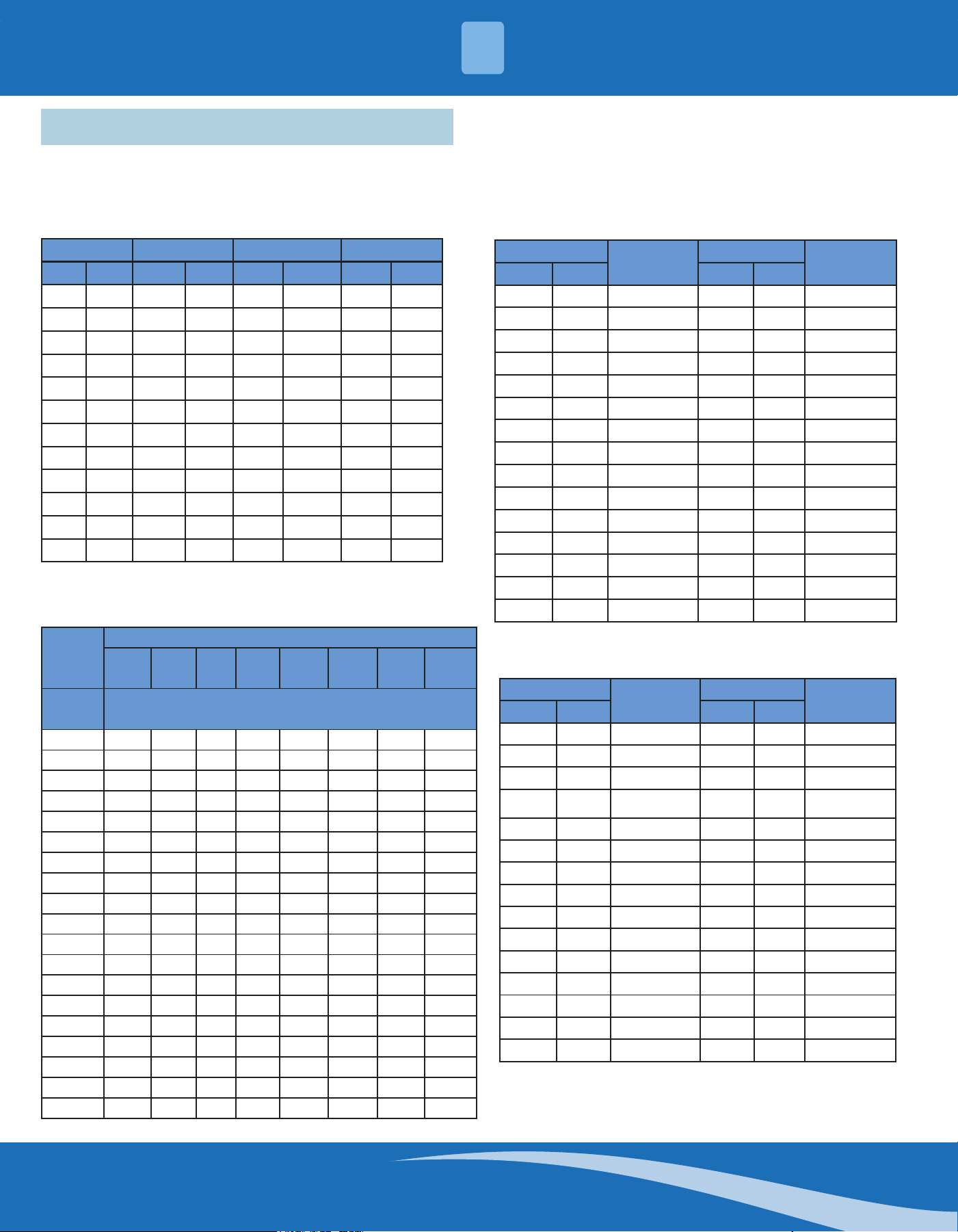
according to Table 4-1.
For appliances serving one or more rooms, the area
calculation should be determined based on the total
area of the conditioned space (TA) connected by
ducts taking into consideration the circulating airow
distributed to all the rooms by the appliance integral
indoor fan will mix and dilute the leaking refrigerant
before entering any room.
Figure 4-1
A(ft
2)
Mc (lb-oz) Mmax (lb-oz)
Anvmin(ft
2
)
lb oz lb oz
100 17 3 6 10 1.3
110 17 3 7 5 1.2
120 17 3 8 0 1.1
130 17 3 8 10 1.0
140 17 3 9 5 1.0
150 17 3 10 0 0.9
160 17 3 10 10 0.8
170 17 3 11 5 0.7
180 17 3 12 0 0.6
190 17 3 12 10 0.5
200 17 3 13 5 0.5
210 17 3 14 0 0.4
220 17 3 14 10 0.3
230 17 3 15 5 0.2
240 17 3 16 0 0.1
250 17 3 16 10 0.1
260 17 3 17 5 0.0
The Minimum Opening Area for Connected Rooms
Table 4-1
Note: Take the Mc=17lb 3oz as an example
NOTE
The requirement for the second opening can be
met by drop ceilings, ventilation ducts, or similar
arrangements that provide an airow path between
the connected rooms.
ROOM AREA LIMITATIONS
4
mrcool.com 18
18
ROOM AREA LIMITATIONS
4
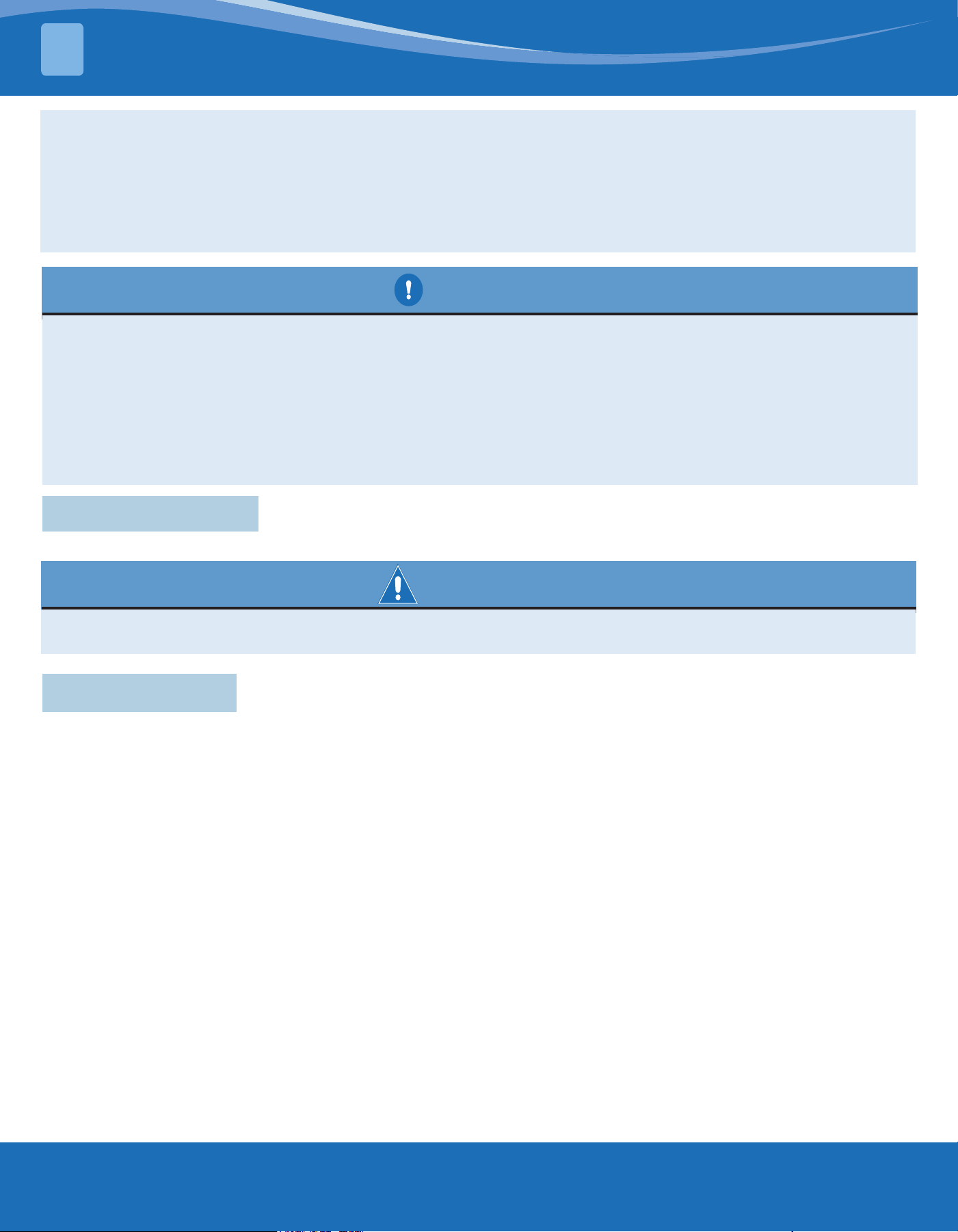
If the fan incorporated in the appliance is continuously operated or operation is initiated by a Refrigerant
Detection System with a sucient circulation airow rate, the allowable maximum refrigerant charge (Mmax)
and the required minimum room area (Amin/TAmin) is shown in Tables 4-2 and 4-3.
Mc (lb-oz)
Amin/
TAmin(ft
2
)
Mc (lb-oz)
Amin/
TAmin(ft
2
)
lb oz lb oz
4 6 66.1 11 0 165.3
4 13 72.7 11 7 171.9
5 4 79.3 11 14 178.5
5 11 86.0 12 5 185.1
6 2 92.6 12 12 191.7
6 9 99.2 13 3 198.4
7 0 105.8 13 10 205.0
7 7 112.4 14 1 211.6
7 15 119.0 14 8 218.2
8 6 125.6 14 15 224.8
8 13 132.2 15 6 231.4
9 4 138.8 15 14 238.0
9 11 145.5 16 5 244.6
10 2 152.1 16 12 251.2
10 9 158.7 17 3 257.9
The Required Minimum Room Area
Table 4-3
A/TA (ft
2
) Mmax(lb-oz) A/TA(ft
2
) Mmax(lb-oz)
ft
2
m
2
lb-oz kg ft
2
m
2
lb-oz kg
30 2.8 2-0 0.9 150 13.9 10-0 4.5
40 3.7 2-9 1.2 160 14.9 10-9 4.8
50 4.6 3-5 1.5 170 15.8 11-4 5.1
60 5.6 3-14 1.8 180 16.7 11-15 5.4
70 6.5 4-9 2.1 190 17.7 12-9 5.7
80 7.4 5-3 2.4 200 18.6 13-4 6.0
90 8.4 5-14 2.7 210 19.5 14-0 6.4
100 9.3 6-9 3.0 220 20.4 14-12 6.7
110 10.2 7-5 3.3 230 21.4 15-7 7.0
120 11.1 7-15 3.6 240 22.3 16-0 7.3
130 12.1 8-9 3.9 250 23.3 16-12 7.6
140 13.0 9-4 4.2 260 24.2 17-13 7.9
The Allowable Maximum Refrigerant Charge
Table 4-2
Mc (lb-oz)
Amin/
TAmin(ft
2
)
Mc (lb-oz)
Amin/
TAmin(ft
2
)
lb oz lb oz
4 6 119 11 0 298
4 13 131 11 7 310
5 4 143 11 14 322
5 11 155 12 5 334
6 2 167 12 12 346
6 9 179 13 3 358
7 0 191 13 10 370
7 7 203 14 1 382
7 15 215 14 8 394
8 6 227 14 15 406
8 13 239 15 6 418
9 4 251 15 14 430
9 11 263 16 5 442
10 2 275 16 12 454
10 9 287 17 3 466
Table 4-4
The Minimum Circulation Airow
4.3 Allowed Maximum Refrigerant Charge
Table 4-5
Altitude (m)
201-
400
401-
600
601-
800
801-
1000
1001-
1200
1201-
1400
1401-
1600
above
1600
Charge
lb
Minimum Conditioned Space (m
2
)
2 2.8 2.8 2.8 2.9 3.0 3.1 3.1 3.2
3 4.2 4.2 4.3 4.4 4.5 4.6 4.7 4.8
4 5.6 5.6 5.7 5.9 6.0 6.1 6.2 6.4
5 7.0 7.0 7.1 7.3 7.5 7.7 7.8 8.0
6 8.4 8.4 8.5 8.8 8.9 9.2 9.4 9.6
7 9.8 9.8 9.9 10.2 10.4 10.7 10.9 11.2
8 11.1 11.1 11.4 11.7 11.9 12.3 12.5 12.8
9 12.5 12.5 12.8 13.2 13.4 13.8 14.0 14.4
10 13.9 13.9 14.2 14.6 14.9 15.3 15.6 16.0
11 15.3 15.3 15.6 16.1 16.4 16.9 17.2 17.6
12 16.7 16.7 17.1 17.6 17.9 18.4 18.7 19.2
13 18.1 18.1 18.5 19.0 19.4 19.9 20.3 20.8
14 19.5 19.5 19.9 20.5 20.9 21.5 21.8 22.4
15 20.9 20.9 21.3 21.9 22.4 23.0 23.4 24.0
16 22.3 22.3 22.7 23.4 23.8 24.5 25.0 25.6
17 23.7 23.7 24.2 24.9 25.3 26.1 26.5 27.2
18 25.1 25.1 25.6 26.3 26.8 27.6 28.1 28.8
19 26.5 26.5 27.0 27.8 28.3 29.1 29.6 30.4
20 27.9 27.9 28.4 29.3 29.8 30.6 31.2 32.0
If the altitude of installation is above 2,000 ft,
the required minimum room area:
mrcool.com19
WIRING
5
CAUTION
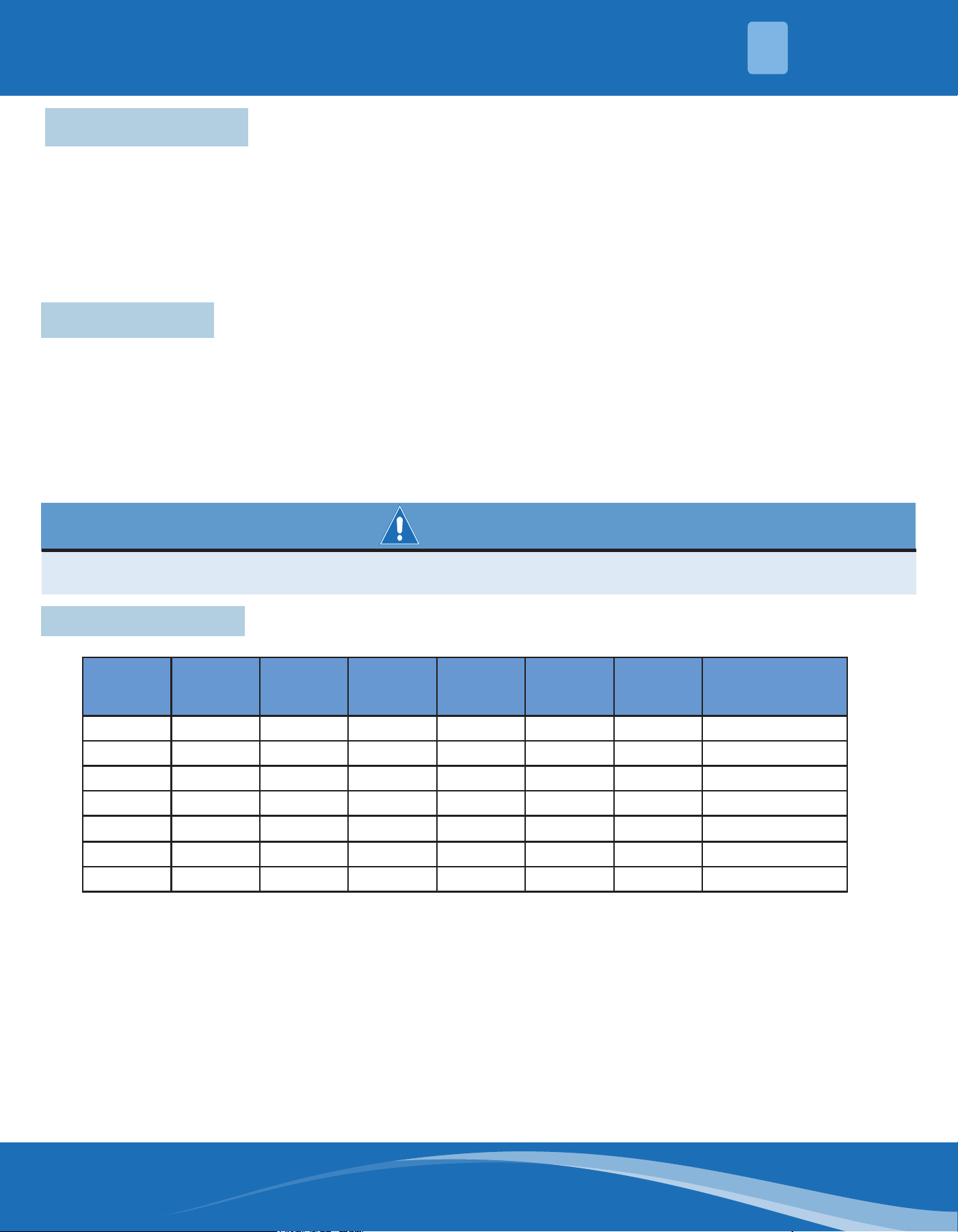
The allowable maximum refrigerant charge of Table 4-2 or the required minimum room area of the Table 4-4
is available only if the following conditions are met:
• Minimum velocity of 3.28 ft/s, which is calculated as the indoor unit airow divided by the nominal face
area of the outlet. The grill area should be deducted.
• Minimum airow rate must meet the corresponding values in Table 4-5, which is related to the actual
refrigerant charge of the system (Mc).
R454B refrigerant leakage sensor is congured:
If the actual room area, air outlet height, and refrigerant charge amount are not reected in Table 4-5, more
severe cases need to be considered according to Tables 4-1, 4-2, 4-3, and 4-4.
5.1 Electrical Wiring
Field wiring must comply with the National Electric Code and any applicable local ordinance.
WARNING
Disconnect all power to the unit before installing or servicing. More than one disconnection switch may be
required to de-energize the equipment. Hazardous voltage can cause severe personal injury or death.
5.2 Power Wiring
It is important proper electrical power is available for connection to the unit model being installed. See the unit
nameplate, wiring diagram, and electrical data in the installation instructions.
• If required, install a branch circuit disconnect of adequate size, located within the sight of and readily
accessible to the unit.
• After the electric heater is installed, unit may be equipped with one, two, or three 30/60 amp. circuit
breakers. These breaker(s) protect the internal wiring in the event of a short circuit and serve as a
disconnect. Circuit breakers installed within the unit do not provide over-current protection of the supply
wiring and therefore may be sized larger than the branch circuit protection.
• Supply circuit power wiring must be 167°F (75°C) minimum copper conductors only. See Electrical Data In
this section for ampacity, wire size and circuit protector requirement. Supply circuit protective devices may
be either fuses or “HACR” type circuit breakers.
• Power wiring may be connected to either the right, left side, or top. Concentric knockouts are provided for
connection of power wiring to unit.
NOTE:
• The maximum refrigerant limit described above applies to unventilated areas. If adding additional
measures, such as areas with mechanical or natural ventilation, the maximum refrigerant charge can be
increased or the minimum room area can be reduced.
• The R454B refrigerant leakage sensor is congured for the indoor unit and meets the incorporated
circulation airow requirements.
• The maximum refrigerant charge or minimum room area can be determined according to Tables 4-2 and
4-3.
mrcool.com 20
20
WIRING
5
5.3 Control Wiring
Class 2 low voltage control wiring should not be run in conduit with main power wiring and must be separated
from power wiring, unless class 1 wire of proper voltage rating is used.
• Low voltage control wiring should be 18 AWG color-coded. For lengths longer than 100 ft, 16 Awg. wire
should be used.
• See wiring diagrams attached to indoor and outdoor sections to be connected.
• Make sure, after installation, separation of control wiring and power wiring has been maintained.
5.4 Grounding
• Grounding may be accomplished by grounding metal conduit when installed in accord and with electrical
codes to the unit cabinet.
• Grounding may also be accomplished by attaching ground wire(s) to ground lug(s) provided in the unit
wiring compartment.
• Ground lug(s) are located close to wire entrance on left side of unit (up-ow). Lug(s) may be moved to
marked locations near wire entrance on right side of unit (upow). If alternate location is more convenient.
• Use of multiple supply circuits require grounding of each circuit to lug(s) provided in unit.
WARNING
The unit must be permanently grounded. Failure to do so can result in electrical shock causing personal injury
or death.
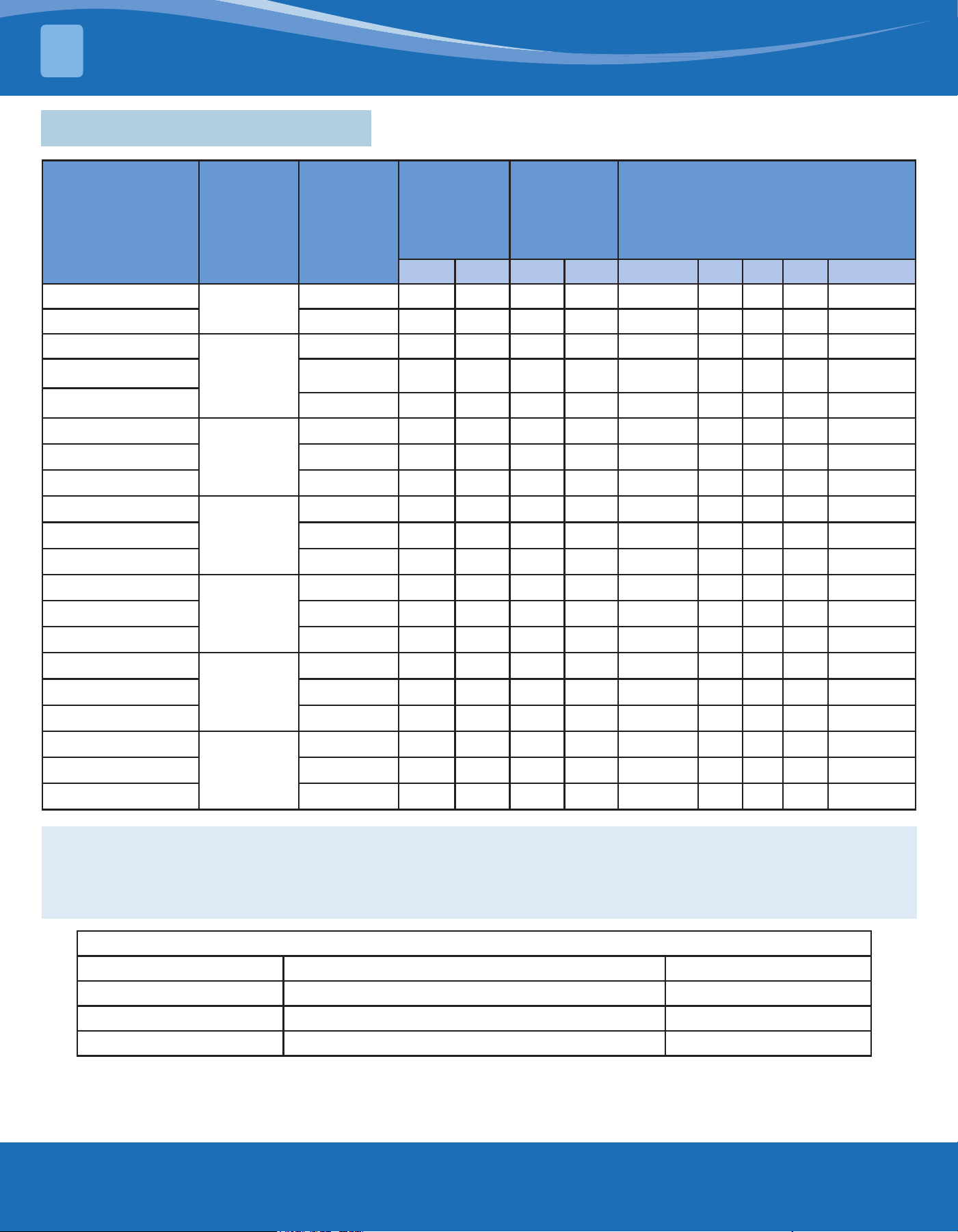
5.5 Electrical Data
Model Voltage Herts HP RPM Speeds
Circuit
Amps.
Maximum
Circuit
Protector
18K 208/230 60 1/4 710 3 1.2 3(A)
24K 208/230 60 2/7 770 3 1.4 3(A)
30K 208/230 60 1/2 1050 5 3.2 6(A)
36K 208/230 60 1/2 1050 5 3.2 6(A)
42K 208/230 60 3/4 1050 5 5.5 10(A)
48K 208/230 60 3/4 1050 5 5.5 10(A)
60K 208/230 60 3/4 1050 5 5.5 10(A)
mrcool.com21
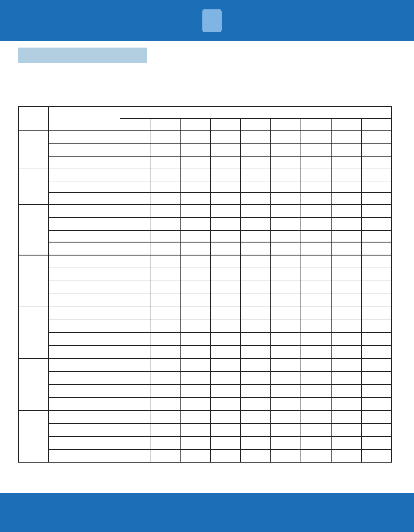
5.6 MCA/MOP Data of Electric Heat Kit
Heat Kit Model
Air
Handler
Model
Electric
Heater
(kW)
MCA(Min.
Circuit
Ampacity)
MOP(Max.
Fuse or
Breaker
(HACR)
Ampacity)
Fan Speed(AC/HP)
208V 230V 208V 230V 1(Low) 2 3 4 5(High)
MCAEHFD5X1AA
18K
5 22.8 24.9 25 25 • / • / •
MCAEHFD7X1AA 7.5 34.8 37.9 35 40 • / • / •
MCAEHFD5X1AA
24K
5 22.8 24.9 25 25 • / • / •
MCAEHFD7X1AA
7.5 34.8 37.9 35 40 • / • / •
MCAEHFD10X1AA
10 45.4 49.8 50 50 • / • / •
MCAEHFD5X1AA
30K
5 22.8 24.9 25 25
X
• • • •
MCAEHFD7X1AA 7.5 34.8 37.9 35 40
X
• • • •
MCAEHFD10X1AA 10 45.4 49.8 50 50
X
• • • •
MCAEHFD5X1AA
36K
5 22.8 24.9 25 25
X
• • • •
MCAEHFD7X1AA 7.5 34.8 37.9 35 40
X
• • • •
MCAEHFD10X1AA 10 45.4 49.8 50 50
X
• • • •
MCAEHFD5X1AA
42K
5 22.8 24.9 25 25
X
• • • •
MCAEHFD7X1AA 7.5 34.8 37.9 35 40
X
• • • •
MCAEHFD10X1AA 10 45.4 49.8 50 50
X
• • • •
MCAEHFD5X1AA
48K
5 22.8 24.9 25 25
X
• • • •
MCAEHFD7X1AA 7.5 34.8 37.9 35 40
X
• • • •
MCAEHFD10X1AA 10 45.4 49.8 50 50
X
• • • •
MCAEHFD5X1AA
60K
5 22.8 24.9 25 25
X X X
• •
MCAEHFD7X1AA 7.5 34.8 37.9 35 40
X X X
• •
MCAEHFD10X1AA 10 45.4 49.8 50 50
X X X
• •
NOTE:
• Heat kit suitable for AHU 4-way position installation.
• Ampacities for MCA and Fuse/breaker including the blower motor.
• Heat pump systems require a specied airow. Each ton of cooling requires between 350 and 450 cubic feet
of air per minute (CFM), or 400 CFM nominally.
Electrical Heater Kits
Model Description Ref. Air Handler Use
MCAEHFD5X1AA 5kW heater kit, double pole circuit breaker 18/24/30/36/42/48/60
MCAEHFD7X1AA 7.5kW heater kit, double pole circuit breaker 18/24/30/36/42/48/60
MCAEHFD10X1AA 10kW heater kit, double pole circuit breaker 24/30/36/42/48/60
WIRING
5
mrcool.com 22
22
Heat Kit Model
Air
Handler
Model
Electric
Heater
(kW)
MCA(Min.
Circuit
Ampacity)
MOP(Max.
Fuse or
Breaker
(HACR)
Ampacity)
Fan Speed(AC/HP)
208V 230V 208V 230V 1(Low) 2 3 4 5(High)
MCAEHFD5X1AA
18K
5 22.8 24.9 25 25 • / • / •
MCAEHFD7X1AA 7.5 34.8 37.9 35 40 • / • / •
MCAEHFD5X1AA
24K
5 22.8 24.9 25 25 • / • / •
MCAEHFD7X1AA
7.5 34.8 37.9 35 40 • / • / •
MCAEHFD10X1AA
10 45.4 49.8 50 50 • / • / •
MCAEHFD5X1AA
30K
5 22.8 24.9 25 25
X
• • • •
MCAEHFD7X1AA 7.5 34.8 37.9 35 40
X
• • • •
MCAEHFD10X1AA 10 45.4 49.8 50 50
X
• • • •
MCAEHFD5X1AA
36K
5 22.8 24.9 25 25
X
• • • •
MCAEHFD7X1AA 7.5 34.8 37.9 35 40
X
• • • •
MCAEHFD10X1AA 10 45.4 49.8 50 50
X
• • • •
MCAEHFD5X1AA
42K
5 22.8 24.9 25 25
X
• • • •
MCAEHFD7X1AA 7.5 34.8 37.9 35 40
X
• • • •
MCAEHFD10X1AA 10 45.4 49.8 50 50
X
• • • •
MCAEHFD5X1AA
48K
5 22.8 24.9 25 25
X
• • • •
MCAEHFD7X1AA 7.5 34.8 37.9 35 40
X
• • • •
MCAEHFD10X1AA 10 45.4 49.8 50 50
X
• • • •
MCAEHFD5X1AA
60K
5 22.8 24.9 25 25
X X X
• •
MCAEHFD7X1AA 7.5 34.8 37.9 35 40
X X X
• •
MCAEHFD10X1AA 10 45.4 49.8 50 50
X X X
• •
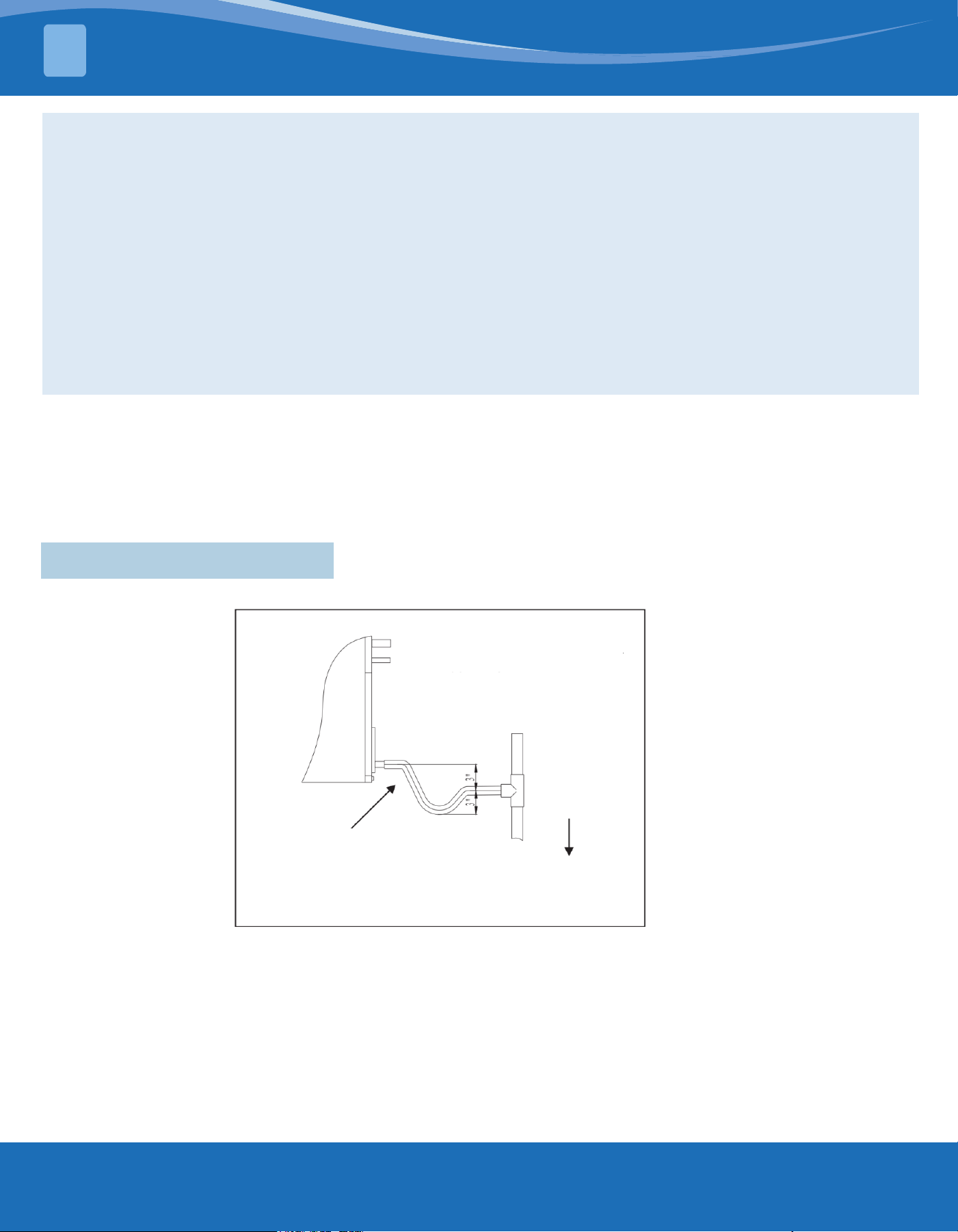
AIRFLOW PERFORMANCE
6
Model Blower Speeds
External Static Pressure (in. w.c.)
0 0.1 0.2 0.3 0.4 0.5 0.6 0.7 0.8
18K
L 887 838 772 683 618 550 507 / /
M-Factory Default 1086 1041 993 932 823 749 673 587 529
H 1134 1090 1039 982 869 784 704 614 528
24K
L-Factory Default 1127 1082 1028 973 856 761 679 574 526
M 1193 1144 1092 1031 897 803 717 622 531
H 1292 1240 1185 1120 1037 885 787 693 553
30K
2 1131 1074 1012 950 893 836 779 727 679
3-Factory Default 1245 1197 1145 1093 1045 983 917 865 817
4 1359 1316 1270 1226 1183 1131 1074 1007 945
5 1449 1411 1368 1325 1287 1245 1197 1126 1059
36K
2 1131 1074 1012 950 893 836 779 727 679
3 1245 1197 1145 1093 1045 983 917 865 817
4-Factory Default 1359 1316 1270 1226 1183 1131 1074 1007 945
5 1449 1411 1368 1325 1287 1245 1197 1126 1059
42K
2 1298 1257 1216 1162 1107 1011 961 918 873
3-Factory Default 1451 1414 1379 1344 1301 1254 1217 1085 1005
4 1588 1550 1512 1476 1440 1402 1368 1202 1035
5 1730 1695 1660 1611 1562 1484 1410 1224 1037
48K
2 1404 1360 1316 1267 1219 1170 1136 1051 964
3 1585 1544 1503 1467 1431 1388 1344 1288 1231
4-Factory Default 1730 1689 1655 1621 1587 1549 1514 1457 1416
5 1887 1852 1815 1780 1745 1707 1681 1599 1517
60K
2 1404 1360 1316 1267 1219 1170 1136 1051 964
3 1585 1544 1503 1467 1431 1388 1344 1288 1231
4-Factory Default 1730 1689 1655 1621 1587 1549 1514 1457 1416
5 1887 1852 1815 1780 1745 1707 1681 1599 1517
Airow performance data is based on cooling performance with a coil and no lter in place. Select performance
table for the appropriate unit size.
External static applied to the unit allows operation within the minimum and maximum limits shown in the table
below for both cooling and electric heat operation.
6.1 Airow Performance Data
mrcool.com23
NOTE:
1. The advanced airow must be used as the rated airow for the full-load operation of the machine.
2. The rated airow of a system without an electric heater kit requires 300 to 450 cubic feet of air per minute
(CFM).
3. The rated airow of a system with an electric heater kit requires 350 to 450 cubic feet of air per
minute(CFM).
4. The air distribution system has the greatest inuence on air ow. Therefore, the contractor should only use
the procedures recognized by the industry.
5. The design and construction of air duct should be done carefully. Poor design or process will lead to a
signicant decline in system performance.
6. The air supply duct should be set along the periphery of the air-conditioned space with appropriate size.
Improper location of insucient airow may lead to insucient ventilation or noise in the pipeline system
7. The installer should balance the air distribution system to ensure that all rooms in the room have proper
quiet airow. The speedometer or airow hood can be used to balance and verify the branch pipe and
system airow (CFM).
• When the 36K model used with the electrical heater kit model HR150-01, you need to ensure that
the air volume is not less than 1100 CFM.
• When the 42K model used with the electrical heater kit model HR150-01 and HR200-01, you need to
ensure that the air volume is not less than 1280 CFM.
• When the 48K model used with the electrical heater kit model HR150-01 and HR200-01, you need to
ensure that the air volume is not less than 1415 CFM.
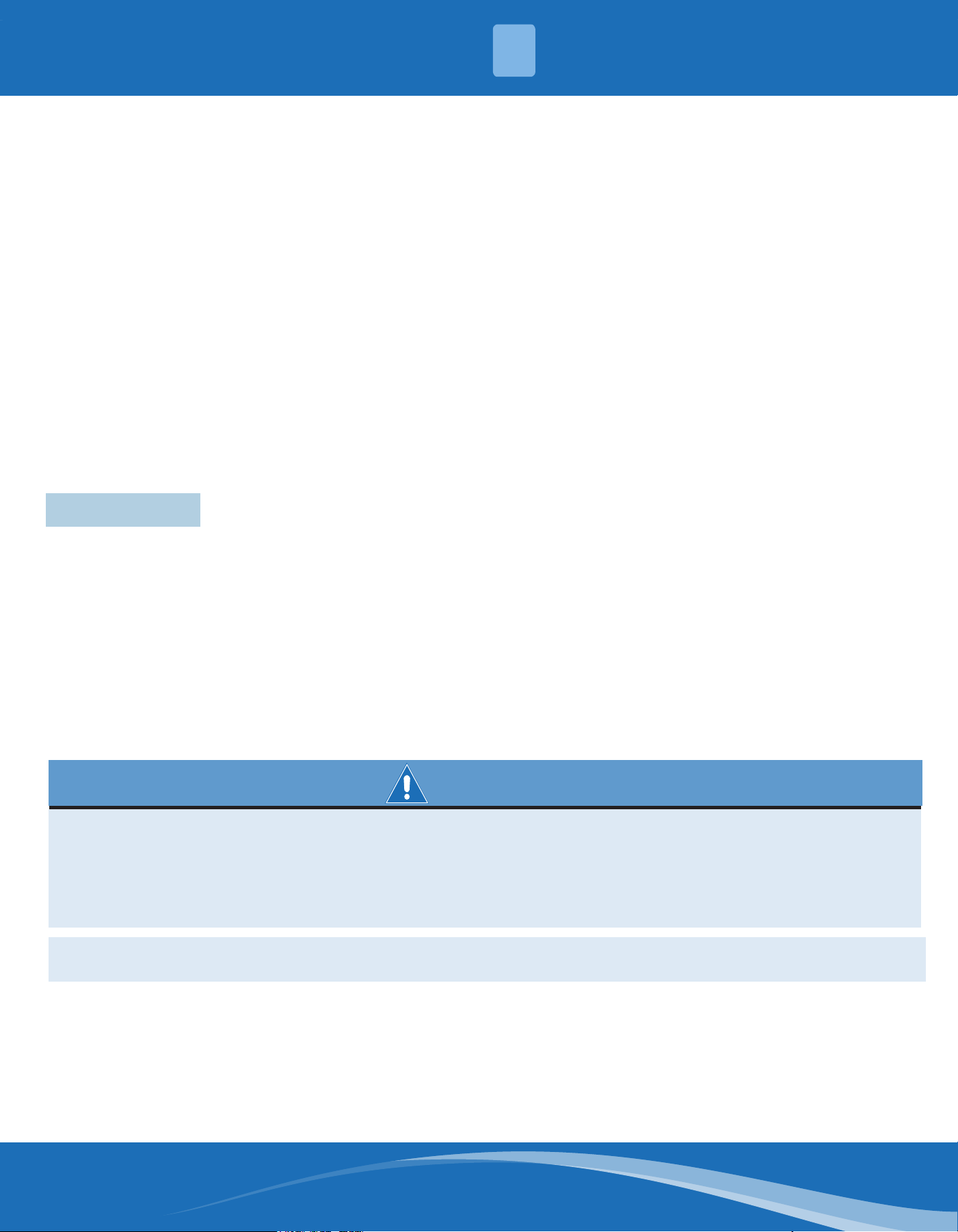
7.1 Condensate Drain Tubing
Consult local codes for specic requirements.
Condensate Drain Trap
Do Not Operate the Unit Without
Condensate Drain Trap.
To Approved Drain
Do Not Overtighten Drain Fitting
Toward Drain Connection Unit Must
Be Slightly Inclined
Figure 7-1
1. When connecting drain ttings to the drain pan, use a thin layer of Teon paste, silicone, or Teon tape and
tighten by hand.
2. Do not over-tighten as this can split the pipe connection to the drain pan.
• Install drain line so they do not block service access to the front of the unit. A minimum clearance of 24
inches is required for lter, coil, or blower removal and service access.
• Make sure the unit is level or pitched slightly toward primary drain connections to ensure water will drain
completely from the pan as indicated in Figure 7-1.
DUCT, DRAIN, & FILTERS
7
mrcool.com 24
24
• External lter or other means of ltration is required. Units should be sized for a maximum of 300 feet/min.
air velocity or what is recommended for the lter type installed.
• Filter application and placement are critical to airow, which may aect the heating and cooling system
performance. Reduced airow can shorten the life of the system’s major components, such as motor, limits,
elements, heat relays, evaporator coil or compressor.
• Consequently, we recommend that the return air duct system have only one lter location. For systems with
a return air lter grill or multiple lter grills, can have a lter installed at each of the return air openings.
• If adding high eciency lters or electronic air ltration systems, it is very important that the air ow is not
reduced. If air ow is reduced the overall performance and eciency of the unit will be reduced. It is strongly
recommended that a professional installation technician is contacted to ensure installation of these such
ltration systems are installed correctly.
NOTE: Do not double lter the return air duct system or the supply air duct system. This will impact the
performance of the unit and reduce airow.
WARNING
• DO NOT operate the system without lters. A portion of the dust entrained in the air may temporarily
lodge in the duct runs and at the supply registers.
• Any circulated dust particles could be heated and charred by contact with the air handler elements. This
residue could soil ceilings, walls, drapes, carpets, and other articles in the house
• Soot damage may occur with lters in place, when certain types of candles, oil lamps, or standing pilots are
burned.
7.2 Air Filter
• Do not reduce drain line size less than connection size provided on condensate drain pan.
• All drain lines must be pitched downward away from the unit at a minimum of 1/8" per foot of line to ensure
proper drainage.
• Do not connect condensate drain line to a closed or open sewer pipe. Run condensate to an open drain or
run line to a safe outdoor area.
• The drain line should be insulated where necessary to prevent sweating and damage due to condensate
forming on the outside surface of the line.
• Make provisions for disconnecting and cleaning of the primary drain line should it become necessary. Install
a 3 inch trap in the primary drain line as close to the unit as possible. Make sure that the top of the trap is
below connection to the drain pan to allow complete drainage of pan. See Figure 7-1.
• Auxiliary drain line should be run to a place where it will be noticeable if it becomes operational.
Homeowner should be warned that a problem exists if water should begin running from the auxiliary drain
line.
• Plug the unused drain connection with the plugs provided in the parts bag, using a thin layer of Teon paste,
silicone or Teon tape to form a water tight seal.
• Test condensate drain pan and drain line after installation is complete. Pour water into drain pan, enough to
ll drain trap and line. Check to make sure drain pan is draining completely, no leaks are found in drain line
ttings, and water is draining from the termination of the primary drain line.
DUCT, DRAIN, & FILTERS
7
mrcool.com25
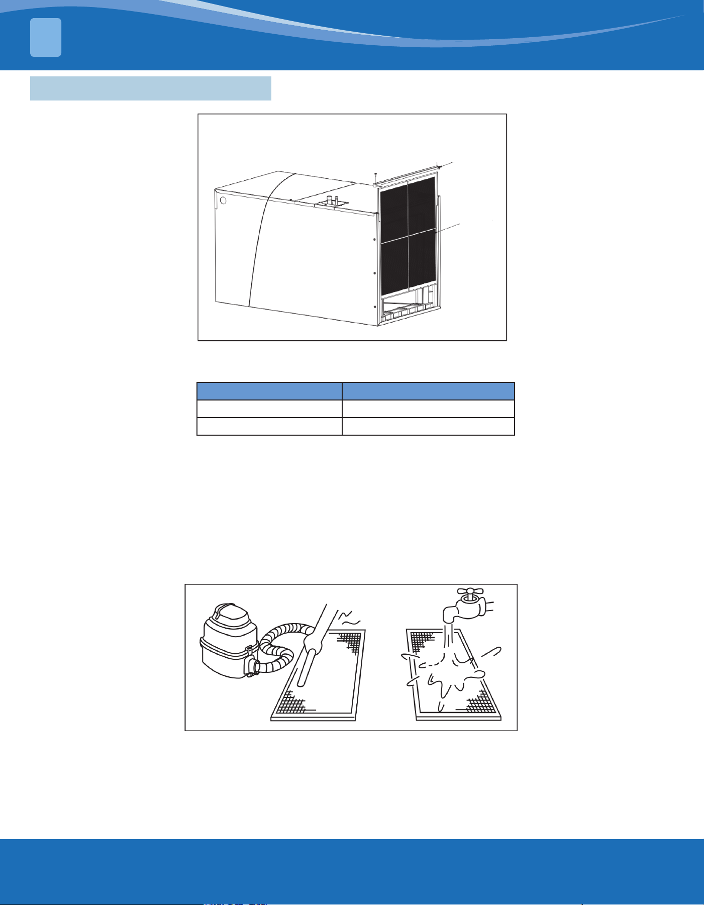
7.3 Filter Installation Dimensions
Cover for
Air Filter
Air Filter
Air Filter Removal:
1. Tear down the bolts signed "A" and "B", take down the cover for the air lter.
2. Hold the edge of the air lter and pull it out.
3. Clean the air lter with a vacuum or water, as indicated in the gure below. If the dust accumulation is too
heavy, use a soft brush and mild detergent to clean and dry out in a cool place.
Model Filter Size in (mm)
18/24/30/36/42K 18.1x21.4 (460x544)
48/60K 20.5x23.8 (521x605)
Note: The thickness of the lter
should be within 1 in (25mm).
Dimensional Data
DUCT, DRAIN, & FILTERS
7
mrcool.com 26
26
WIRING DIAGRAM
8
1. To avoid the electrical shock, please connect the air conditioner with the ground lug. The main
power plug in the air conditioner has been joined with the ground wiring, please don't change it
freely.
2. The power socket is used exclusively with the air conditioner.
3. Don't pull the power wiring hard.
4. When connecting the air conditioner with the ground wire, observe the local codes.
5. If necessary, use the power fuse or the circuit, breaker, or corresponding scale ampere.
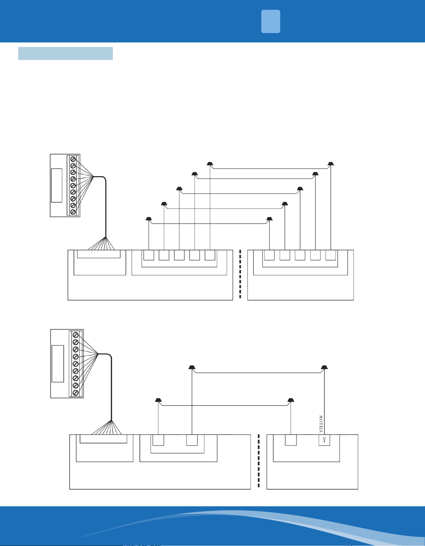
Yellow
Wiring Connection for A/C Systems
Outdoor Unit
Indoor Unit
To Thermostat
Terminal
Thermostat
Terminal
Brown
Brown
Yellow
C
C
Y
Y
Wiring Connection for H/P Systems
Thermostat
To Thermostat
Indoor Unit Outdoor Unit
Terminal
Terminal
Brown
Brown
Blue
Blue
Yellow
Yellow
White
White
Red
Red
C C
B B
Y
Y
W
W
R
R
8.1 Wiring Diagram
mrcool.com27
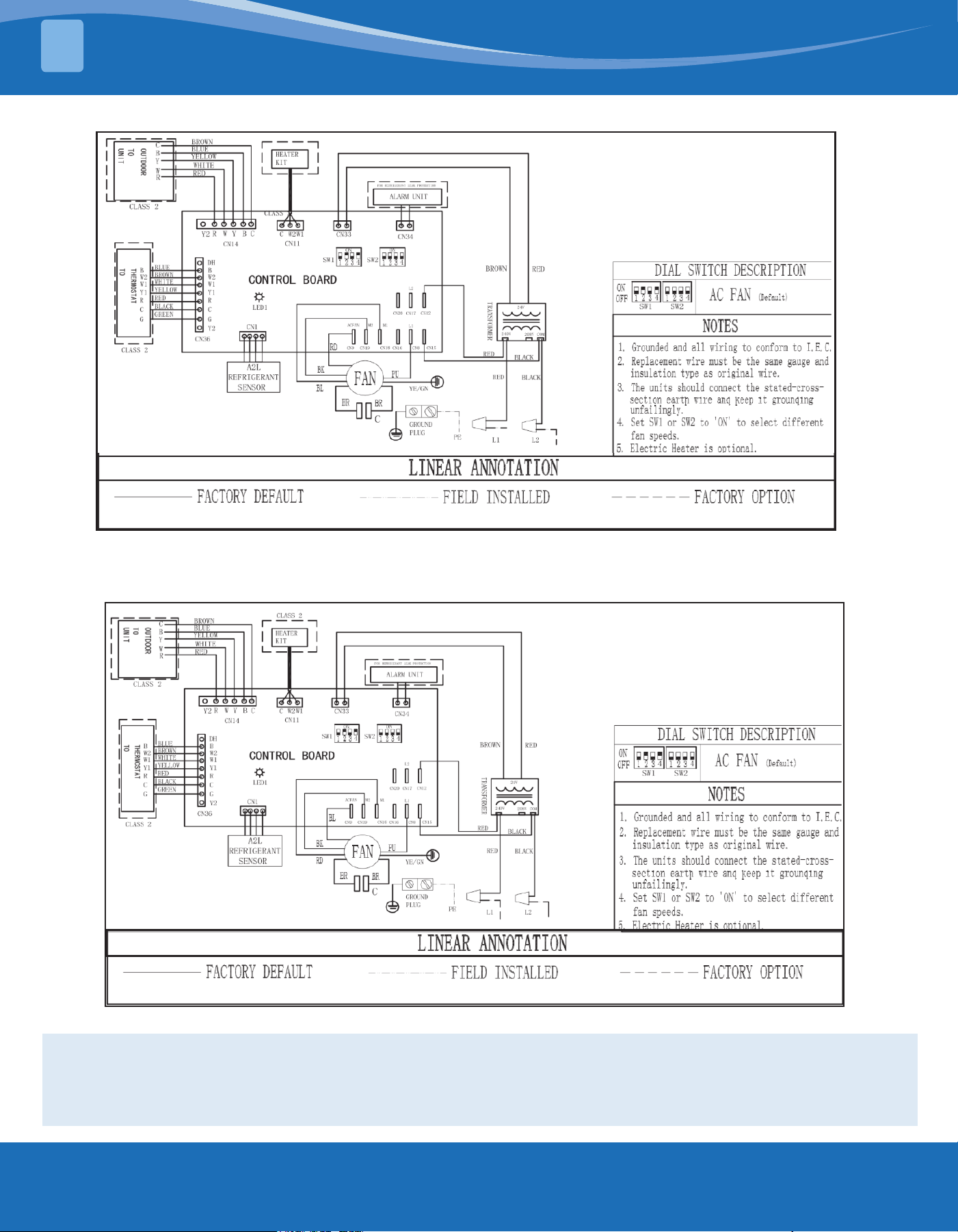
NOTE FOR SPEED SWITCH:
• Low windshield: The red motor of the motor is connected to the terminal block and the blue wire is
connected to the relay (swap plug positions).
• Medium speed wiring: The blue wire of the motor is connected to the terminal block and the red wire is
connected to the relay (swap plug positions).
24k Model:
18k Model:
Please refer to the actual wiring diagram.
Please refer to the actual wiring diagram.
WIRING DIAGRAM
8
mrcool.com 28
28
WIRING DIAGRAM
8
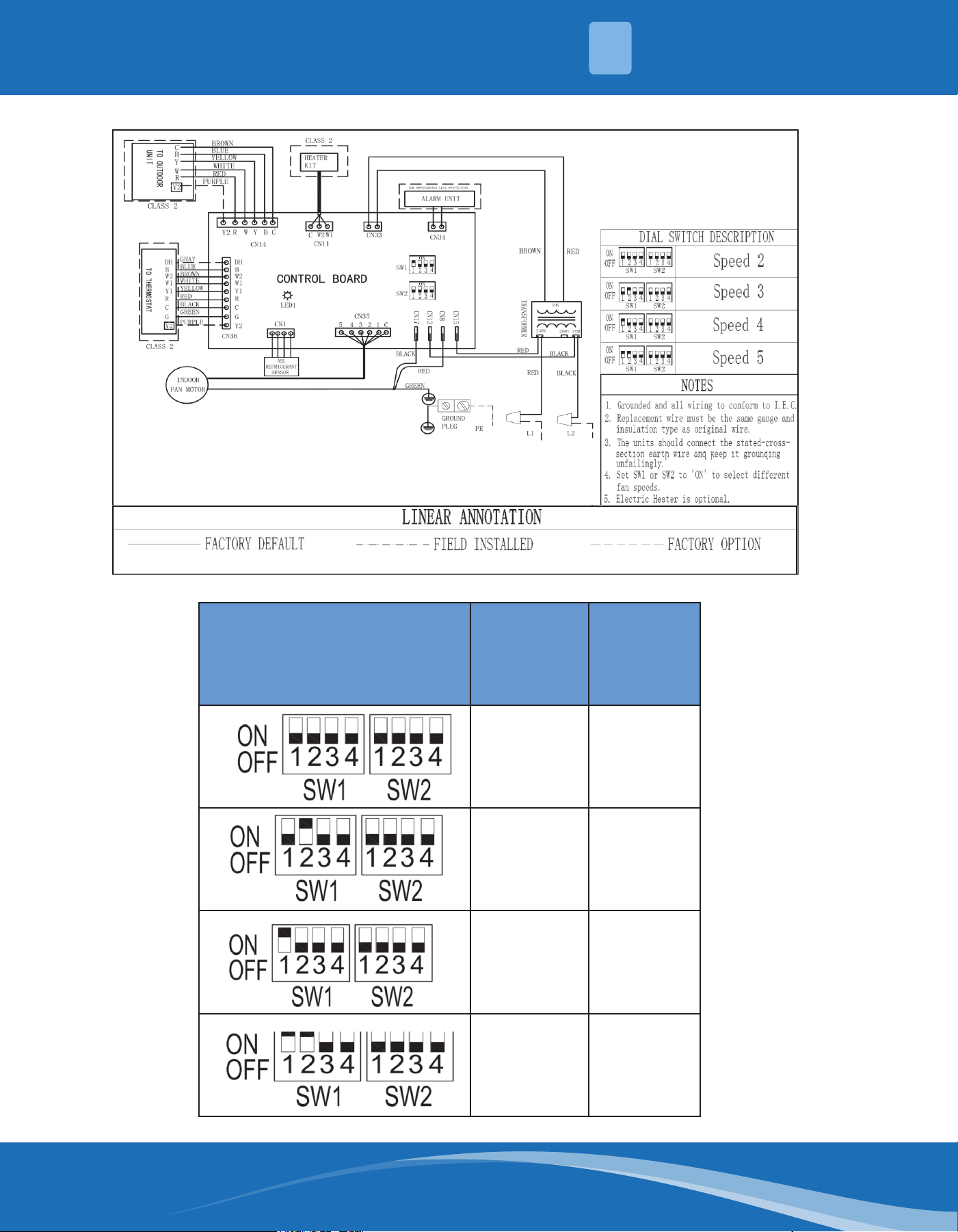
DIP Switch Fan Speed Model
Speed 2 18k/24k
Speed 3 30k
Speed 4 36k/60k
Speed 5 48k
30k/36k/42k/48k/60k Model:
Please refer to the actual wiring diagram.
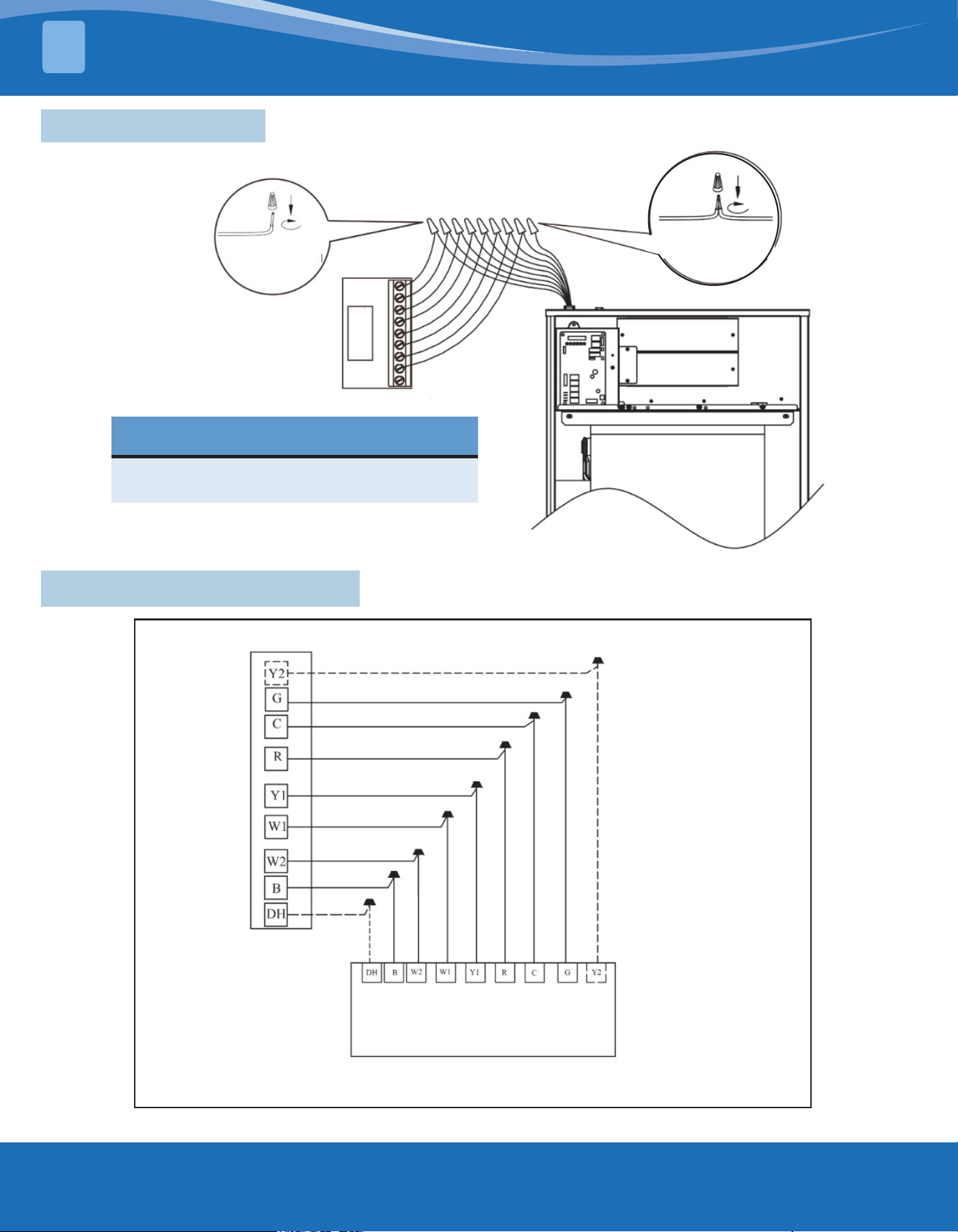
mrcool.com29
8.3 Thermostat Wiring Diagram
Gray
Blue
Brown
White
Yellow
Red
Black
Green
Purple
Indoor Unit
Thermostat
DH: Gray
B: Blue
W2: Brown
W1: White
Y1: Yellow
R: Red
C: Black
G: Green
Y2: Purple
Cap and Seal the
Unused Wire
8.2 Wire Connection
Connect the wires
by wire nut
The unused
wires should be
insulated
Thermostat
Terminal
NOTE
Please secure the cable after it is connected
with the wire nut.
WIRING DIAGRAM
8
mrcool.com 30
30
WIRING DIAGRAM
8
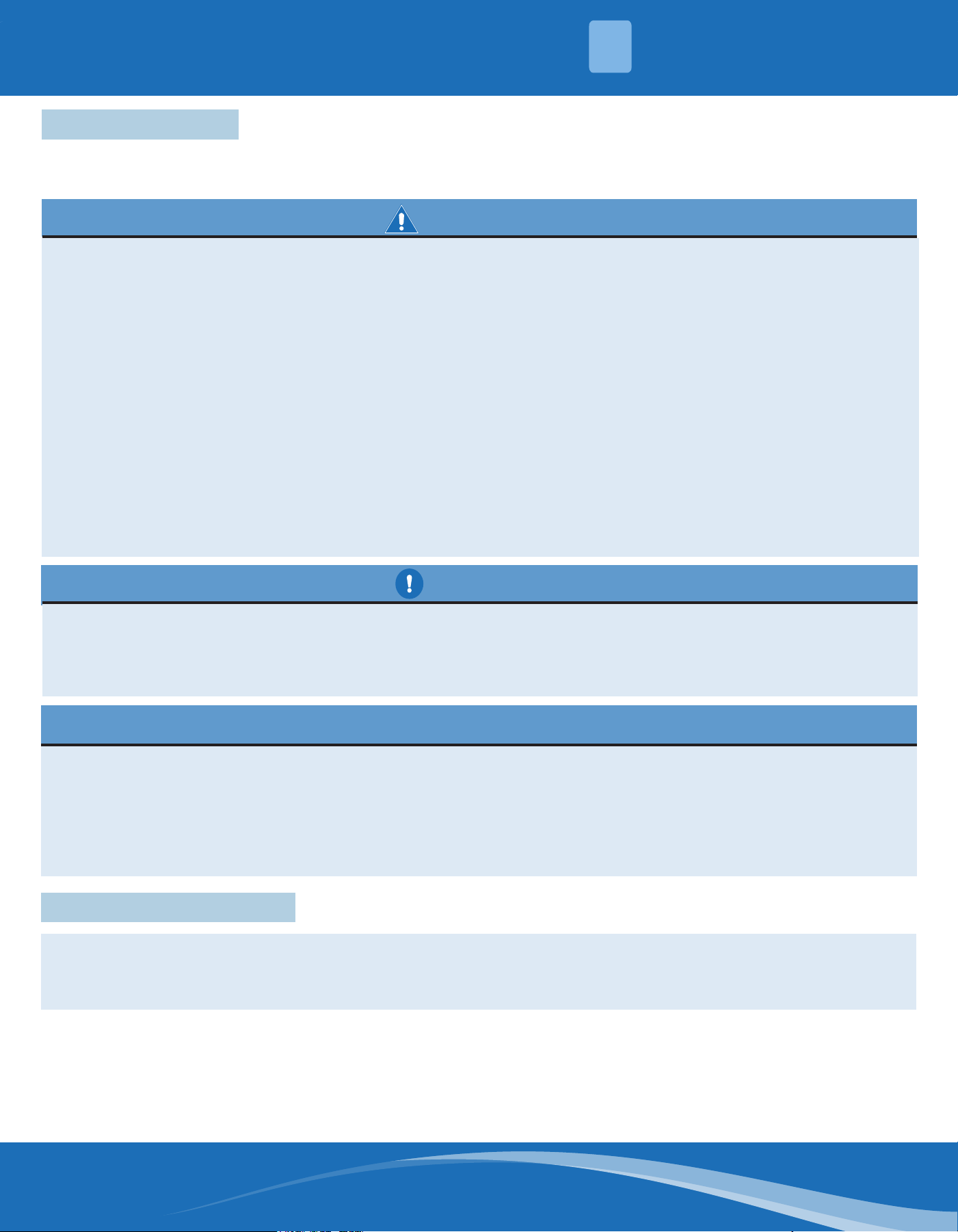
CAUTION
• Sharp metal edges can cause injury. When installing the unit, use care to avoid sharp edges.
• Avoid sharp metal edges for wires to prevent wear, or it may lead to short circuit or electric leakage and cause
danger.
• Wires should be xed well. Otherwise, the connectors may be loose or the terminal may be damaged when they
are pulled.
NOTE
• Electrostatic discharge can aect electronic components. Take care during unit installation and service
to protect the unit’s electronic controls. Precautions will help to avoid control exposure to electrostatic
discharge by putting the unit, the control and the technician at the same electrostatic potential. It is
strongly recommended to contact a professional installation technician to ensure the correct installation of
such ltration systems.
• Do not add phase junction capacitors, otherwise it may cause serious damage to the product.
• Do not start the unit before installing pipes. Otherwise, the compressor will be damaged.
WARNING
• Installation and servicing of air conditioning equipment can be hazardous due to internal refrigerant
pressure and live electrical components. Only trained and qualied service personnel should install or
service this equipment. Installation and service performed by unqualied persons can result in property
damage, personal injury, or death.
• Risk of electrical shock. Disconnect all remote power supplies before installing or servicing any portion of
the system. Failure to disconnect power supplies can result in property damage, personal injury, or death.
• Fire Hazard. Use of aluminum wire with this product may result in a re, causing property damage, severe
injury or death. Use copper wire only with this product.
• Can cause injury or death. Unit must be properly grounded in accordance with national and local codes.
• Natural grounding poles embedded in the ground can be used, but do not connect the ground wire to the
following locations:
a. Pipes of ammable or explosive gases, which may otherwise lead to an explosion or re.
b. Insulated plastic pipes, otherwise there is no grounding eect.
c. Telephone line or lightning rod, otherwise it will be dangerous for increasing the ground potential during
lightning strikes.
• The unit must be permanently grounded. Failure to do so can result in electrical shock causing personal
injury or death.
In the United States, wiring must conform with current local codes and the current National Electric Code (NEC).
In Canada, wiring must conform with current local codes and the current Canadian Electrical Code.
8.4 Power Wiring
8.5 Electric Wiring Gauge
NOTE:
The cross-section areas of wires or lines should not be less than the corresponding ones listed in the table below. If the
power wires are too far from the unit, please choose the windings with the larger cross-section area to guarantee the
normal power supply.
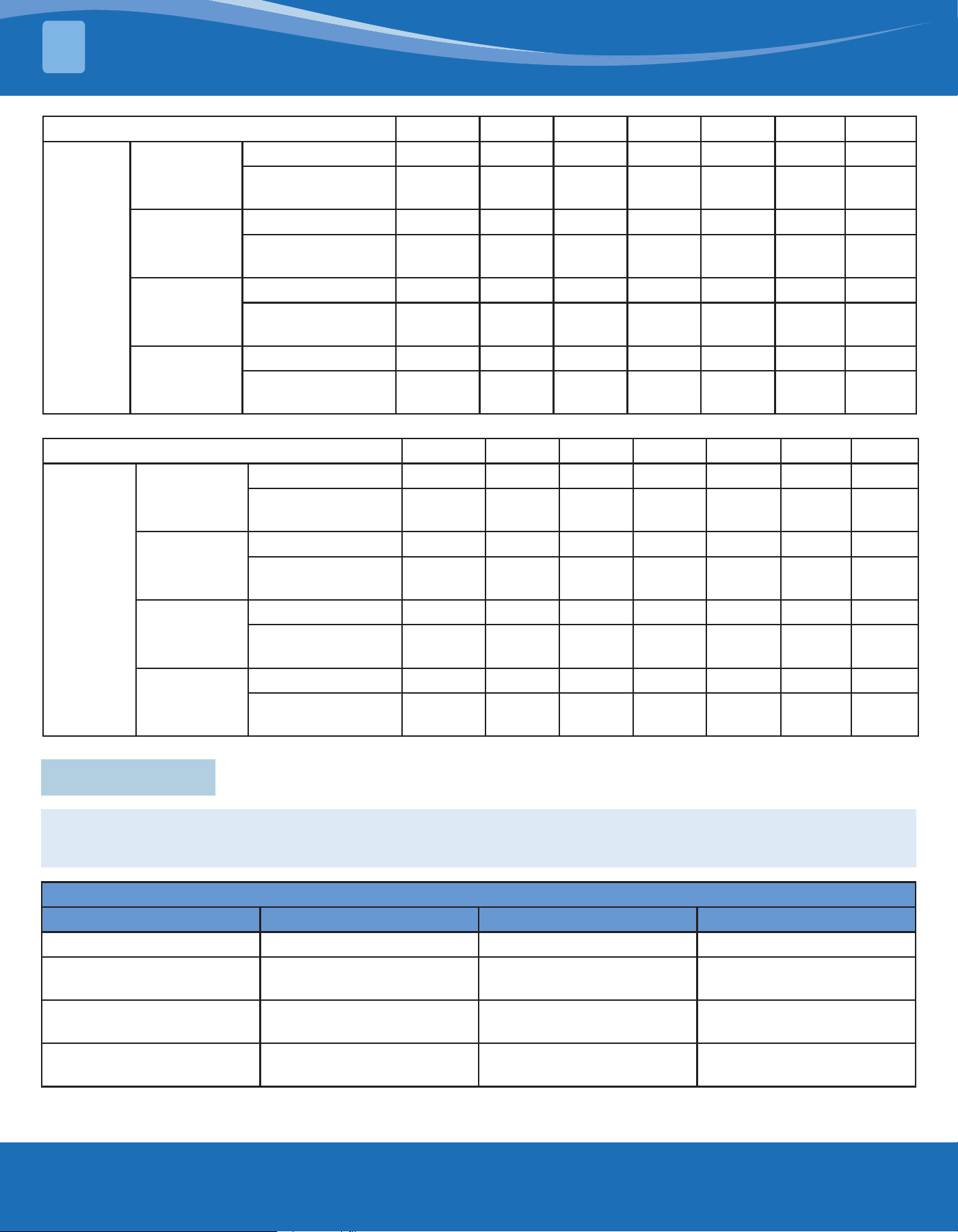
mrcool.com31
ERROR CODES
9
Model (cooling only type) 18K 24K 30K 36K 42K 48K 60K
Line
Gauge
Indoor Unit
Power Line
Line Quantity 3 3 3 3 3 3 3
Line
Diameter(AWG)
16 16 16 16 16 16 16
Outdoor
Unit Power
Line
Line Quantity 3 3 3 3 3 3 3
Line
Diameter(AWG)
14 14 12 12 10 10 8
Indoor-
Thermostat
Signal Line
Line Quantity 5 5 5 5 5 5 5
Line
Diameter(AWG)
18 18 18 18 18 18 18
Outdoor-
Thermostat
Signal Line
Line Quantity 2 2 2 2 2 2 2
Line
Diameter(AWG)
18 18 18 18 18 18 18
Model (cooling & heating type) 18K 24K 30K 36K 42K 48K 60K
Line
Gauge
Indoor Unit
Power Line
Line Quantity 3 3 3 3 3 3 3
Line
Diameter(AWG)
16 16 16 16 16 16 16
Outdoor
Unit Power
Line
Line Quantity 3 3 3 3 3 3 3
Line
Diameter(AWG)
14 14 12 12 10 10 8
Indoor-
Thermostat
Signal Line
Line Quantity 5 5 5 5 5 5 5
Line
Diameter(AWG)
18 18 18 18 18 18 18
Outdoor-
Thermostat
Signal Line
Line Quantity 5 5 5 5 5 5 5
Line
Diameter(AWG)
18 18 18 18 18 18 18
-Error Codes
The LED and Buzzer Status
Model Green LED Red LED Buzzer Status
Normal Operation On O Inactive
Refrigerant Sensor Fault On
Flash 3 times and then
powered o for 3 seconds
Active
Refrigerant Sensor
Communition Fault
On
Flash 4 times and then
powered o for 3 seconds
Active
Refrigerant Leak Alarm On
Flash 5 times and then
powered o for 3 seconds
Active
NOTE:
Leak detection system installed. Unit must be powered on except during servicing. If a refrigerant leakage alarm is
observed, do not open the unit or turn it o.

Contents
mrcool.com32
MRCOOL
®
Signature
Series Multi-Position
Air Handler
The design and specications of this product and/or manual are subject to change without prior notice.
Consult with the sales agency or manufacturer for details.