USER AND INSTALLATION MANUAL
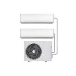
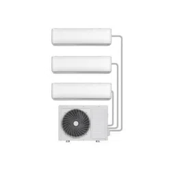
WHITE
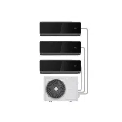
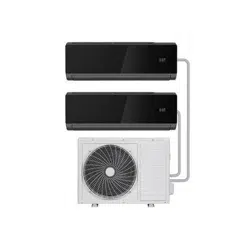
BLACK
iQool-2MS9K9K
iQool-2MS9K9KB
2 x 9,000 BTU Indoor
iQool-2MS12K12K
iQool-2MS12K12KB
2 x 12,000 BTU Indoor
SMART WIFI CONTROLLED WALL MOUNTED INVERTER
MULTI SPLIT AIR CONDITIONER WITH HEAT PUMP
Thank you for choosing an electriQ Air Conditioner
Please read this user manual before using this innovative
Air Conditioner and keep it safe for future reference.

2
CONTENTS
CONTENTS 2
SAFETY INSTRUCTIONS 3
HOW SPLIT AIR CONDITIONERS WORK 5
OPERATION 6
INDOOR UNIT 6
OUTDOOR UNIT 6
REMOTE CONTROL 7
SETTING UP THE REMOTE 8
DISPLAY PANEL 8
FUNCTIONS 9
WIFI CONTROL 12
BEFORE YOU START 12
DOWNLOAD THE APP TO YOUR PHONE 12
ACTIVATING THE APP 13
REGISTER THE APP 13
EMAIL REGISTRATION 13
SMS REGISTRATION 14
FORGOTTEN PASSWORD 14
CONNECTION METHODS AVAILABLE FOR SETUP 15
CHANGING BETWEEN CONNECTION TYPES 15
ADDING A DEVICE 15
CONNECTING USING CF MODE (QUICK CONNECTION) 16
CONNECTING USING AP MODE (ALTERNATIVE METHOD) 17
USING THE TIMER FUNCTION 20
MORE SETTINGS 21
MAINTENANCE 22
END OF SEASON 23
START OF SEASON 23
REPLACING THE BATTERIES 23
INSTALLATION GUIDE 24
TOOLS RECOMMENDED FOR INSTALLATION 27
INFORMATION REGARDING THE INSTALLATION OF THE INDOOR UNIT 29
INSTALLATION OF THE OUTDOOR UNIT 30
CONDENSATE DRAINAGE OF THE OUTDOOR UNIT 30
INSTALL THE WATER DRAINAGE PIPE 32
ELECTRICAL CONNECTION OF THE AIR CONDITIONER 34
ELECTRICAL WIRING DIAGRAMS 34
TROUBLESHOOTING AND SELF DIAGNOSIS 36
WIFI CONTROL TROUBLESHOOTING 39
TECHNICAL SPECIFICATION 40
APPENDIX 41

3
SAFETY INSTRUCTIONS
IMPORTANT!
• Carefully read the instructions before operating the unit
• This appliance comprises of two indoor units and an outdoor unit. The indoor slim
evaporators are designed exclusively for indoor installations while the external
condenser can be installed outside while still away from flood water or snow line.
• Always place the unit on a dry and stable surface. Install the outdoor unit on a wall with
wall-mounting brackets or fix to a floor slab with special floor mounting slab bolts or
brackets away from flood or snow lines.
• Rating: This unit must be only connected to a 220-240 V / 50 Hz earthed power source.
• Installation must be in accordance with the regulations of the country where the unit is
used.
• This appliance is intended for permanent installation into a fixed structure, and should
not be installed on vehicles.
• The outdoor part of the air conditioner unit must always be stored and transported
upright, otherwise irreparable damage may be caused to the compressor; if in doubt we
suggest waiting at least 24 hours before starting the unit.
• These air conditioners are supplied with pre flared refrigeration pipes and electrical
cables, which enables the installer to reduce the installation time.
• European Union regulations requires for an F-Gas trained engineer to handle any
operation where non-qualified intervention could cause fluorinated gas to escape. A
commissioning certificate must be issued with any installation.
• This air conditioner contains R32 which is a safe efficient refrigerant which has a lower
environmental burden than traditional refrigerants.
• The refrigerant used in this air conditioner is an environmentally friendly hydrocarbon
R32, which has a very low Global Warming Potential compared to traditional
refrigerants.
• R32 is classed as slightly flammable and as such naked flames and sources of ignition
should be kept a safe distance from the unit.
• If you are in any doubt about the suitability of your electrical supply have it checked
and, if necessary, modified by a qualified electrician.
• This air conditioner has been tested and is safe to use. However, as with any electrical
appliance - use it with care.
• Disconnect the power before dismantling, assembling or cleaning.
• Never connect the unit to an electrical outlet using an extension cord. Both the indoor
unit and outdoor must be hardwired by a qualified electrician.
• Never operate this appliance if the cord is damaged. Ensure the power cord is not
stretched or exposed to sharp objects or edges.
• A damaged supply cord should be replaced by the manufacturer or a qualified
electrician in order to avoid a hazard.
• Avoid touching any moving parts within the appliance.
• Never insert fingers, pencils or any other objects through the guard
• This appliance is not intended for use by persons (including children) with reduced
physical, sensory or mental capabilities. It is also not intended for use by those with a
lack of experience and knowledge, unless they have been given supervision or
instruction concerning the use of the appliance by a person responsible for their safety.
Do not leave children unsupervised with this appliance.

4
• Do not clean the unit by spraying it or immersing it in water.
• Any service other than regular cleaning or filter replacement should be performed by an
authorized service representative or a qualified air conditioning engineer. Failure to
comply could result in a voided warranty.
• This air conditioner is intended for cooling / heating a room to a suitable level for
human comfort, and should not be used for any other purpose such as cooling food.
• Avoid restarting the air conditioning unit unless 3 minutes have passed since being
turned off. This prevents damage to the compressor.
• Never use the mains as a switch to start and turn off the air conditioning unit. Use the
provided ON/OFF button located on the remote control.
• The indoor unit should not be installed in laundry or wet rooms.
• Diagrams and pictures provided within the manual are for guidance only. Due to
continual product development, if there is any variance between the manual and the
product received, the information provided on the product should be followed.
ENERGY SAVING AND UNIT SAFETY PROTECTION TIPS
• Do not cover or restrict the airflow from the outlet or inlet grills.
• For maximum performance the minimum distance from a wall or objects should be 50cm.
• Keep the filters clean. Under normal conditions, filters should only need cleaning once every
four weeks (approximately). Since the filters remove airborne particles, more frequent cleaning
maybe necessary, depending on the air quality.
• For the initial startup set the fan speed to maximum and the thermostat to 4-5 degrees lower
than the current temperature. After, set the fan switch to low and set the thermostat to your
desired setting.
• To protect the unit we recommend not using the cooling mode when the ambient indoor
temperature is higher than 35℃.
• To protect the unit we recommend not using the heating mode when the indoor ambient
temperature is lower than 7℃. Performance will be reduced at lower temperatures.
• Note the manufacturer operating temperature ranges at the end of this user manual.
5
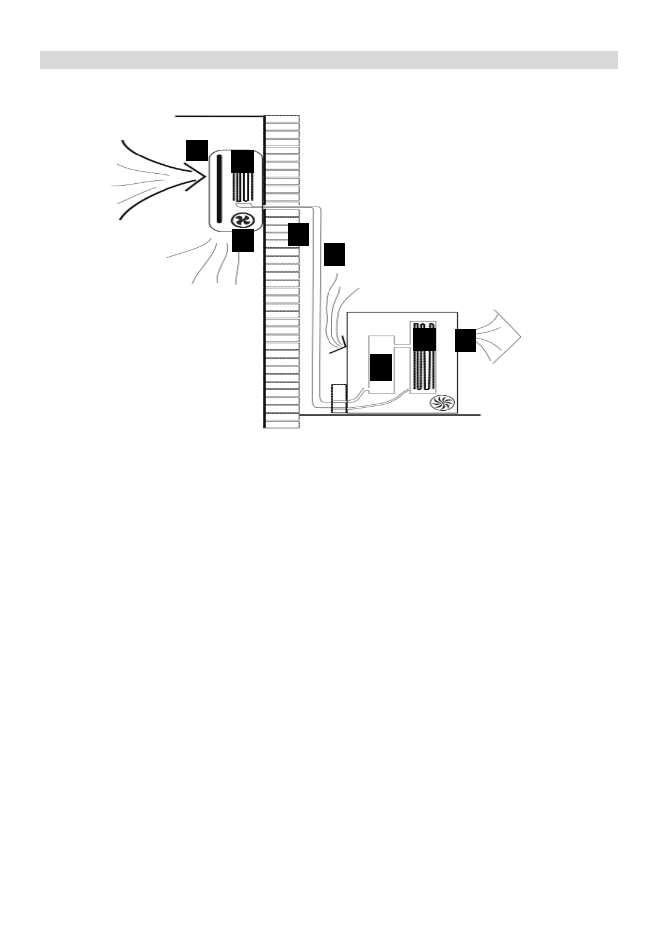
HOW SPLIT AIR CONDITIONERS WORK
COOLING MODE
The compressor (6) in the external unit compresses the refrigerant into a high-temperature, high-
pressure gas. When this gas flows along the cooling fins of the condenser (7), heat is exuded and
the gas condenses into a liquid, which is then led to the evaporator (1) in the indoor unit. The liquid
expands into a gas at a low temperature and low pressure. This gas absorbs the warmth of the air
in the room, and a fan (3) draws the air through the filter and over the evaporator (1), blowing the
cooled air back into the room. The heat is moved to the compressor along with the gas. A fan (8)
draws air over the condenser and blows the warm air away.
1. Evaporator
2. Filter
3. Evaporator Fan
4. Gas Line
5. Liquid line
6. Compressor
7. Condenser
8. Condenser Fan
HEAT PUMP MODE
The system operates in reverse: the condenser works as an evaporator, the evaporator as
a condenser: warm air is blown into the room. It is ideal as a maintenance heating when
outside temperature is not too low and when the indoor temperature is more than 7°C.
DEHUMIDIFYING
As with cooling, the moisture in the air condenses on the cold evaporator at room
temperature acting as a powerful dehumidifier.
NOTE:
This is a multisplit system and multiple indoor units are connected to a single outdoor compressor.
Please make sure that the indoor units are set to operate in the same mode. Multiple indoor units
connected to the same compressor cannot operate in different modes at the same time although
you are able to set different target room temperatures for each unit. Fan only mode can be
operated while other units are in heating or cooling.
3
1
2
4
5
6
8
7
6
OPERATION
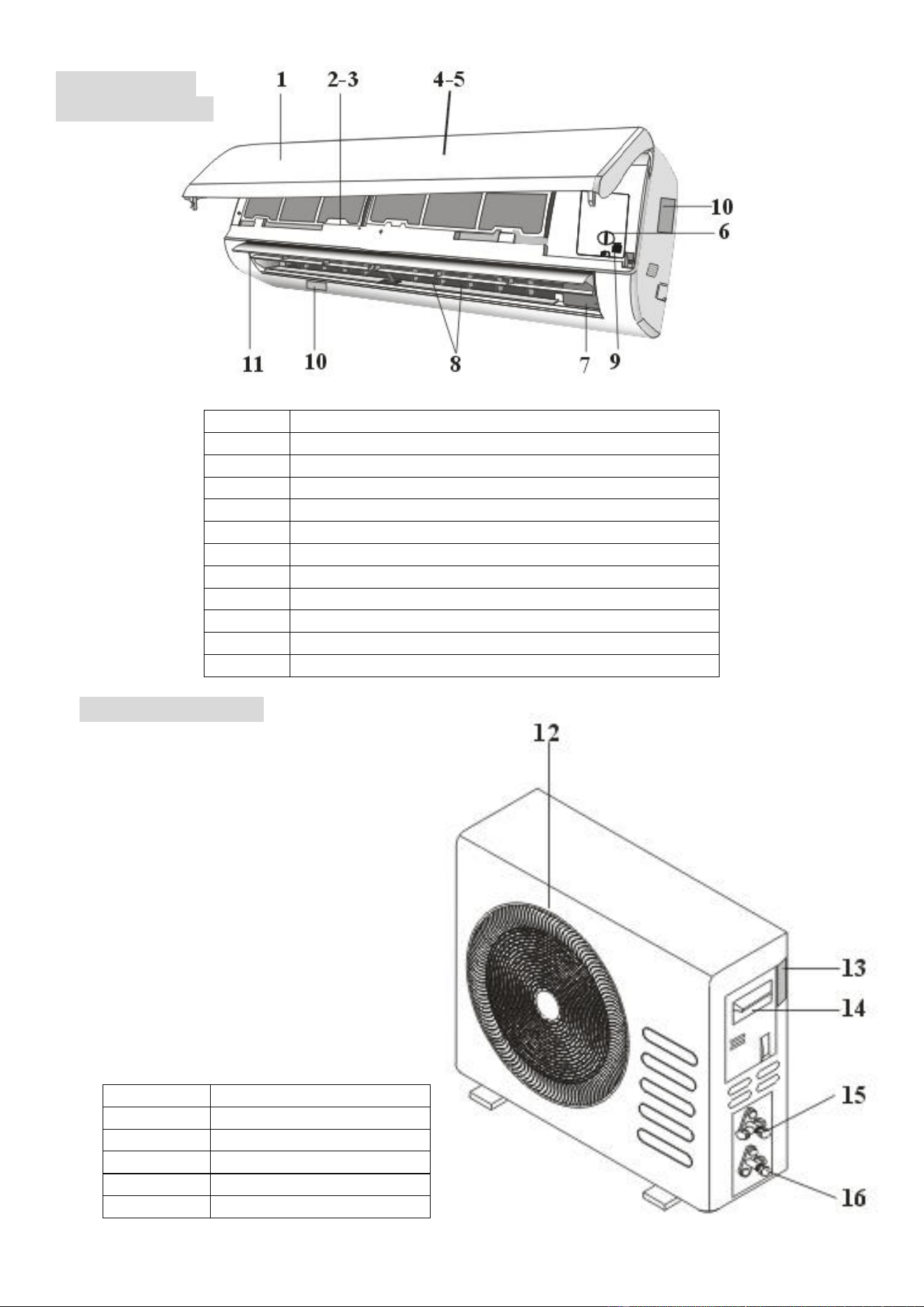
INDOOR UNIT
OUTDOOR UNIT
No.
Description
1
Front panel
2
Air filter
3
Optional filter
4
LED Display
5
Signal receiver
6
Terminal block cover
7
Ionizer generator (not applicable on all models)
8
Deflectors
9
Emergency button
10
Indoor unit rating label
11
Airflow direction louver
No.
Description
12
Air outlet grille
13
Outdoor unit rating label
14
Terminal block cover
15
Gas valve
16
Liquid valve
7
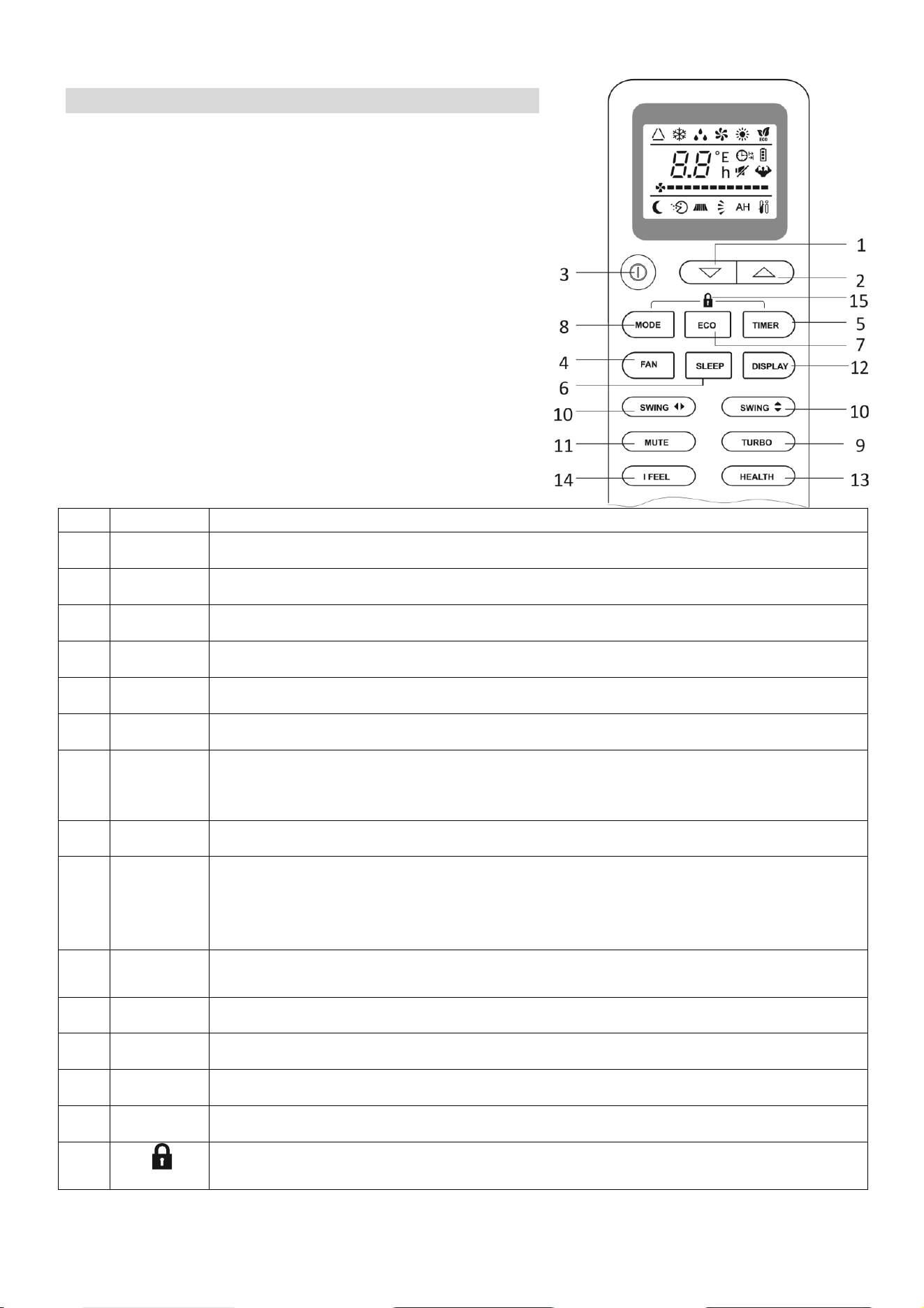
REMOTE CONTROL
The remote control has a range of up to 8m. Point the
remote control at the receiver in the interior unit. A beep
confirms that the remote control signal has been
received.
REMOTE OPERATION
Turn the appliance on using the ON/OFF button. This
activates the most recently used setting.
The ON/OFF
button also turns the air conditioner off.
*Horizontal swing not available on most models and the
horizontal direction must be adjusted manually.
No.
Button
Function
1
Down
Press to decrease the desired room temperature.
2
Up
Press to increase the desired room temperature.
3
Power
Press to turn the unit on or off.
4
Fan
Press to select the fan speed between LOW, MED and HIGH.
5
Timer
Press to set the timer.
6
Sleep
Press to activate the “SLEEP” function
7
Eco
Press to turn eco mode on or off.
In cooling mode eco mode slowly increases the desired temperature by 2
o
C.
In heating mode eco mode slowly decreases the desired temperature by 2
o
C
8
Mode
Press to change between the different modes.
9
Turbo
Press to activate turbo mode. This will make the unit work in high
performance mode to quickly cool or heat the room for a period of 15
minutes. The fan will be set to max, the temperature will be set to either
16
o
C in cooling mode or 31
o
C in heating mode.
10
Swing
Select the vertical direction of airflow (Horizontal direction not adjustable on
these models)
11
Mute
Press to reduce the fan speed to produce the lowest possible wind noise.
12
Display
Press to turn on/off the LED display.
13
Health
Press to activate the ioniser function (Not applicable)
14
I Feel
Press to activate the follow me function.
15
(MODE+TIMER)
Press to activate the child lock function. All buttons on the remote are locked
until the child lock is deactivated.
8
3
4
2
TEMPERATURE
The desired temperature is set with the up and/or down button, within the limits of the
thermostat: 16°C – 31°C.
Use the FAN SPEED button to set the fan speed at low, medium and high; or automatic (the
symbol on the display will flash). The fan speed in the automatic setting is determined by the
difference between the set temperature and the room temperature.
SETTING UP THE REMOTE
When batteries are first inserted into the remote or following changing the batteries, the remote
must be set up for COOLING AND HEATING or COOLING ONLY.
When the batteries are inserted the cool and heat symbols will alternate on the screen of the
remote. For HEATING AND COOLING press any button while the heat symbol is shown.
If the remote is set up for the wrong type of unit, simply remove the batteries and reinsert, before
following the step above.
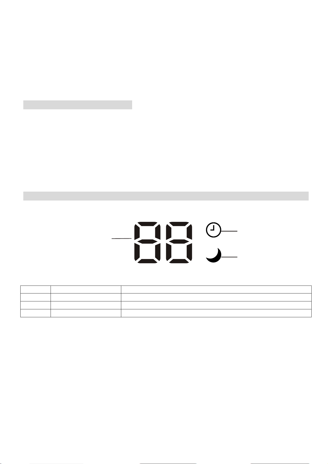
DISPLAY PANEL
No.
Display
Function
2
SLEEP
Illuminated in sleep mode
3
Temp. / Error code
Shows the temperature / error code
4
TIMER
Illuminated when timer is activated
9
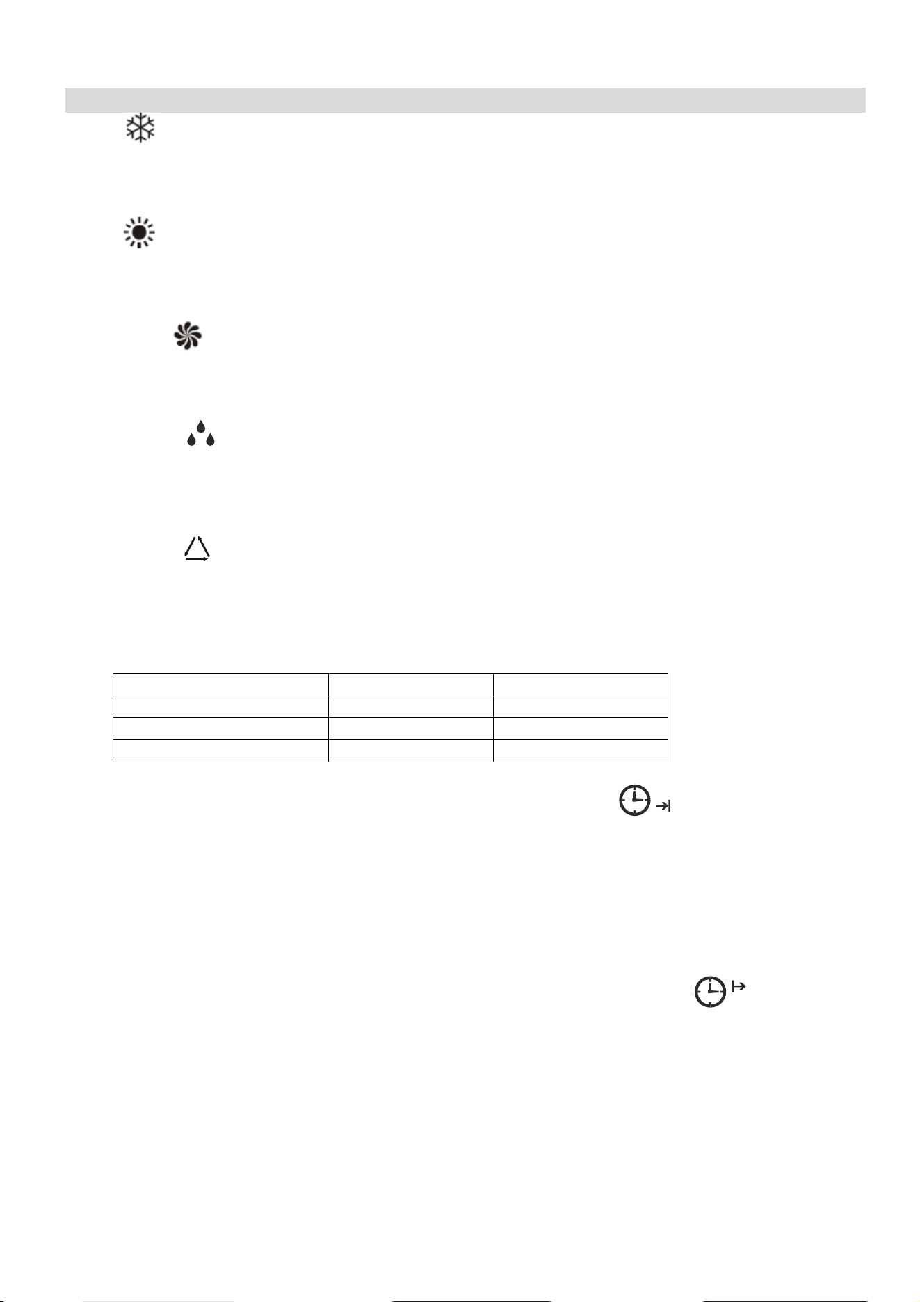
FUNCTIONS
COOL
1. Press the MODE button until the COOL indicator appears.
2. Set the desired temperature.
3.
Use the FAN button
to set the fan speed.
HEAT
1. Press the MODE button until the HEAT indicator appears
2. Set the desired temperature.
3. Use the FAN button to set the fan speed.
FAN MODE
1. Press MODE
button until the FAN indicator appears.
2. The temperature settings are disabled in fan mode.
3. Use the FAN button to set the fan speed, cycling through LOW / MED / HIGH / AUTO.
DEHUMIDIFY
1. Press the MODE
button until the dehumidify indicator appears.
2. The fan speed will always be low in this mode and the FAN button is disabled. In addition
the temperature cannot be adjusted in dehumidifying mode
AUTO MODE
1. Press the MODE button until the AUTO indicator appears.
2. The difference between the set temperature and room temperature determines how the air
conditioner operates: cool, heat, fan or dry. It is not possible to change the temperature in
this mode the unit will operate to achieve best performance. The operation logic is as
below.
Ambient Temperature
Operation Mode
Auto Temperature
˂20°C
Heating
23°C
20°C - 26°C
Dry
18°C
˃26°C
Cool
23°C
3. Use the FAN button to set the fan speed.
TIMER OFF FUNCTION (WHILE THE AIR CONDITIONER IS ON)
1. Press the MODE button until the symbol appears for the operation you want.
2. Set the desired temperature.
3. Use the FAN button to set the fan speed.
4. Press the TIMER button to set the running time required. Use the up and down buttons to
set the running time in 30 minute intervals (max 24 hours). Once the running time has
elapsed, the appliance will switch itself off. To cancel the timer function before the set time
has elapsed, press the TIMER button again.
TIMER ON FUNCTION (WHILE THE AIR CONDITIONER IS IN STANDBY)
1. The appliance is switched off in standby mode
2. Press the TIMER button to set the number of hours until switch on is required. Use the up
and down button set the number of hours in 30 min intervals (max 24 hours). Set the
desired operation, temperature, fan speed. Once the set time has elapsed, the appliance
will switch itself on. To turn off the timer function before the set time has elapsed, press the
TIMER button again.
10
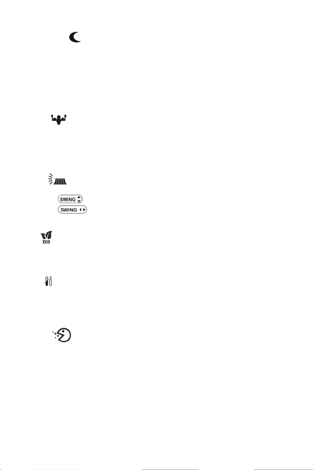
SLEEP MODE
1. Press the SLEEP button
2. Set the desired temperature.
3. Press the SLEEP button; The SLEEP indicator will appear on the display. Cancel the
sleep mode by pressing the button again.
4. The fan will operate at low speed.
5. The temperature is automatically altered by 1
o
C every hour for 2 hours. In cooling mode
the temperature will rise, in heating it will fall.
6. After 10 hours in Sleep mode the unit will power off automatically.
TURBO
1. Press the TURBO button until the Turbo symbol appears.
2. Set the desired temperature.
3. Use the FAN button to set the fan speed
4. Press the TURBO button. The fan and compressor will run at maximum speed for 15
minutes, before returning to their previously set levels.
SWING
1. Press the SWING buttons to control the fan direction.
2. The controls the horizontal air movement (up/down)
3. The button is not activated on this model, and the horizontal direction of the
airflow can be adjusted manually.
ECO
1. Press the ECO button to turn on the energy saving mode
2. In cooling mode, the desired temperature will increase by 2
o
C.
3. In heating mode, the desired temperature will decrease by 2
o
C.
IFEEL
1. Press the IFEEL button to activate the follow me mode.
2. In this mode the temperature of the unit will be set based on the temperature where the
remote is situated.
3. The remote will act as a mobile thermostat which controls the unit.
HEALTH
1. Press the Health button to activate the antibacterial ioniser function.
2. The ionizer helps to eliminate pollutants in the air.
PLEASE NOTE: The Health mode can only be used on units containing a built in ioniser.

11
IMPORTANT INFORMATION
HEATING MODE
When the air conditioner is placed in heating mode, the indoor unit will appear to be inactive
while it follows it’s preheat procedure to heat the evaporator coils. Once the coils have heated,
the indoor fan will start to run. This process usually takes 1 – 3 minutes, and is designed to
ensure that cold air is not circulated.
AUTO RESTART
The air conditioner will automatically restart when electricity is restored after a power cut. If in
doubt, check the settings.
RANGE OF INTERNAL THERMOSTAT
The internal thermostat can be set at a desired temperature between 16 and 31°C. Note that
whether the desired value is achieved depends on the room size, temperature and insulation of
the room.
RANGE OF HEAT PUMP FUNCTION
The heat function can be used when the external ambient temperature is above -15°C. The
performance of the heat pump will degrade with lowering external temperatures. Please note the
performance will reduce when the outdoor temperature drops below 5°C.
CAPACITY
The required cooling or heating capacity depends greatly on the location and/or use of the room
where the air conditioner is installed. Strong sunlight and the presence of people, lights or
equipment creates an additional heat load. Normal living spaces require about 350 Btu per
square metre of floor surface. In strong sunlight or if other sources of heat are present, this may
be as much as 1200 Btu per sqm.
Tip: On warm days, let the air conditioner cool the room as much as possible during the night and
keep the temperature constant from night to daytime.
EMERGENCY START
In the event of a problem, the air conditioner can be operated using the emergency button under
the panel in the indoor unit. Open the front panel and press the button, the air conditioner will:
-heat if the room temperature is 20 °C or less, cool if the room temperature is 25 °C or more and
for values in between will operate in fan mode.
SELECTING THE OPERATIONAL MODE
This is a multisplit system and multiple indoor units are connected to a single outdoor
compressor. Please make sure that the indoor units are set to operate in the same mode. Multiple
indoor units connected to the same compressor cannot operate in different modes at the same
time although you are able to set different target room temperatures for each unit. Fan only mode
can be operated while other units are in heating or cooling.

12
WIFI CONTROL
BEFORE YOU START
• Ensure your router provides a standard 2.4ghz connection.
• If your router is dual band ensure that both networks have different network names (SSID).
The provider of your router / ISP will be able to provide advice specific to your router.
• Once the app has been installed on your phone, turn off the data connection, and ensure
your phone is connected to your router via wifi.
DOWNLOAD THE APP TO YOUR PHONE
Please note that your air conditioner requires a good signal during the setup process. Your air
conditioner is designed to be connected to a 2.4ghz network, and the connection is set up using
the Tuya “SMART LIFE” app. We would advise on using the QR codes below to ensure the
correct app is downloaded.
Android IOS
The unit can also be controlled using the “Smart Life” app by TUYA which is also available in the
app stores. We would advise on using the version above which is optimised for use with your air
conditioner as we cannot guarantee the correct functionality of all features with the TUYA app. If
you would prefer to use the TUYA app, please use the QR codes below
Android IOS
13
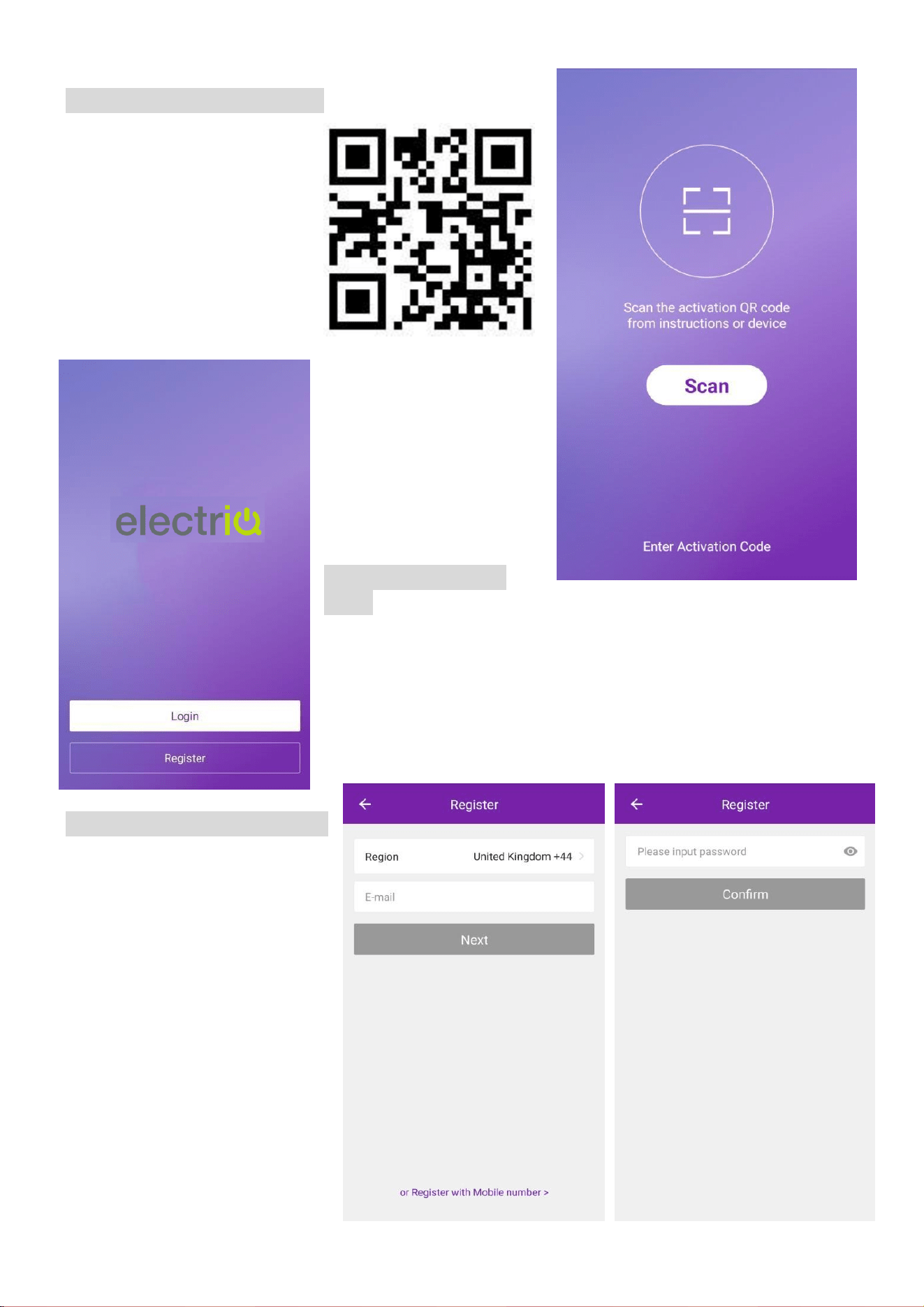
ACTIVATING THE APP
The first time the app is
used, it will need activating.
To do this, either press the
scan button, and scan the
QR code below, or press
“Enter Activation Code” and
enter the activation code:
electriQ
REGISTER THE
APP
Upon the first use, an account will need to be registered. Click
on the “Register” button to enter the registration screen. The
account can be created by using either the default option of an
email address, or alternatively by SMS message using the
“Register with mobile number” option.
EMAIL REGISTRATION
Enter your email address, and
Press next. In the password
box create a new password for
your account, before
pressing confirm. This
should be at least 6 characters
and include letters and
numbers.
14
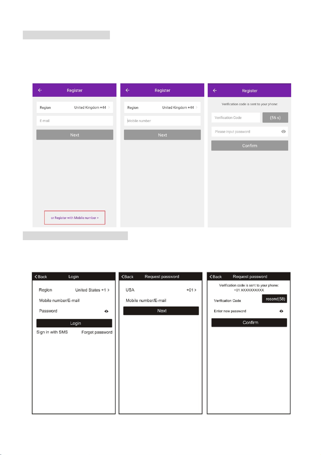
SMS REGISTRATION
Press on the option at the bottom of the screen to choose the option for registering with a mobile
number. You will receive an activation code via SMS. Enter the activation code into the
verification code box, before entering your new password in the box below.
Please note the password should be at least 6 characters and include letters and numbers.
Then press the confirm button to log in.
FORGOTTEN PASSWORD
Should the password for your account be forgotten, it is possible to use the “Forgot Password”
option which will allow you to enter the email address or telephone number used to register the
account, and a verification code will be sent to you via the method chosen.
15
CONNECTION METHODS AVAILABLE FOR SETUP
The air conditioner has two different setup modes, CF (Quick Connection) and AP (Access
Point). The CF mode is a quick and simple way to set the unit up. The AP connection uses a
direct local wifi connection between your phone and the air conditioner to upload the network
details.
Before starting the setup, please ensure that your air conditioner is in the correct standby mode
for the connection type you are attempting, the display on the air conditioner will confirm the
current connection mode during setup.
Please note: Each indoor unit is classed as a separate device within the app and as such the
following connection process should be repeated for each indoor unit.
CHANGING BETWEEN CONNECTION TYPES
To change the unit between the two connection types, quickly press the display button on the
remote 6 times, and wait approx. 10 seconds until the new connection mode is displayed on the
panel of the air conditioner.
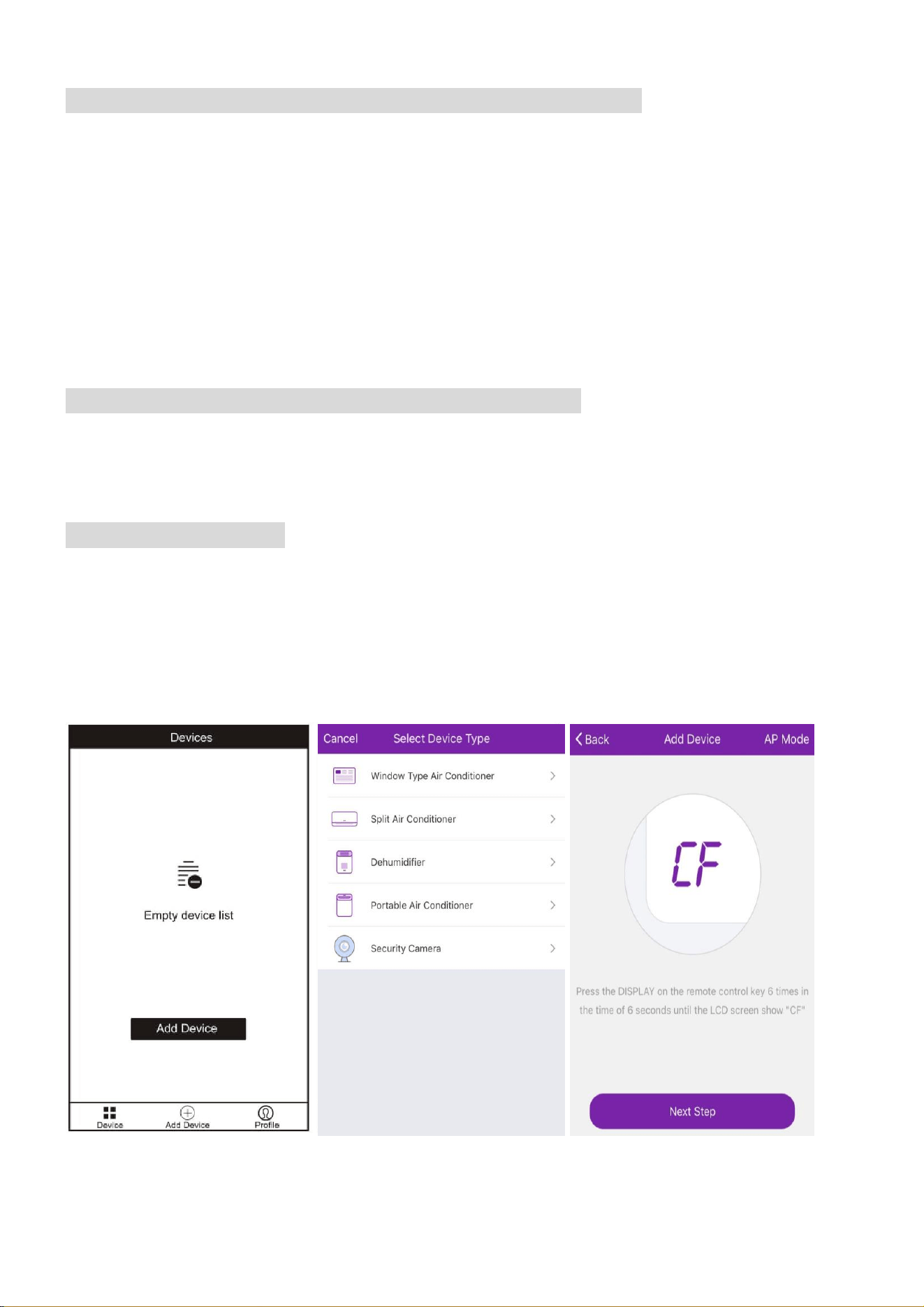
ADDING A DEVICE
1. Press the “Add device” button, which will bring up a screen to choose the device type.
2. Select “Split Air Conditioner” from the Device Type List.
3. The app will default to quick connection mode, and this can be changed by pressing the
button labelled AP Mode in the top right of the screen.
4. After ensuring that the air conditioner is also in the correct connection mode, follow the
relevant connection guide on the following pages.
16
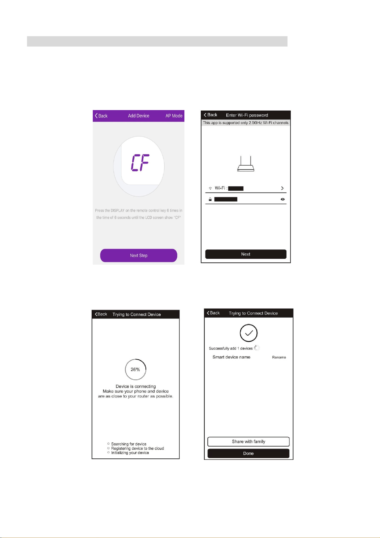
CONNECTING USING CF MODE (QUICK CONNECTION)
1. Ensure that the display on the air conditioner is displaying CF before pressing “Next Step”
(otherwise to change the connection mode: Quickly press the display button on the remote 6
times and wait 10 seconds until CF is displayed)
2. Select your Wifi router from the drop down list and enter the password (Please note the
password is case sensitive) before pressing next.
The app will automatically upload the connection information to the air conditioner, once the
connection is completed, a message will be displayed to confirm. On this page there is the
option to rename the air conditioner to something more relevant.
If the connection fails, please retry the connection, failing this try connecting using the AP mode
connection.
17
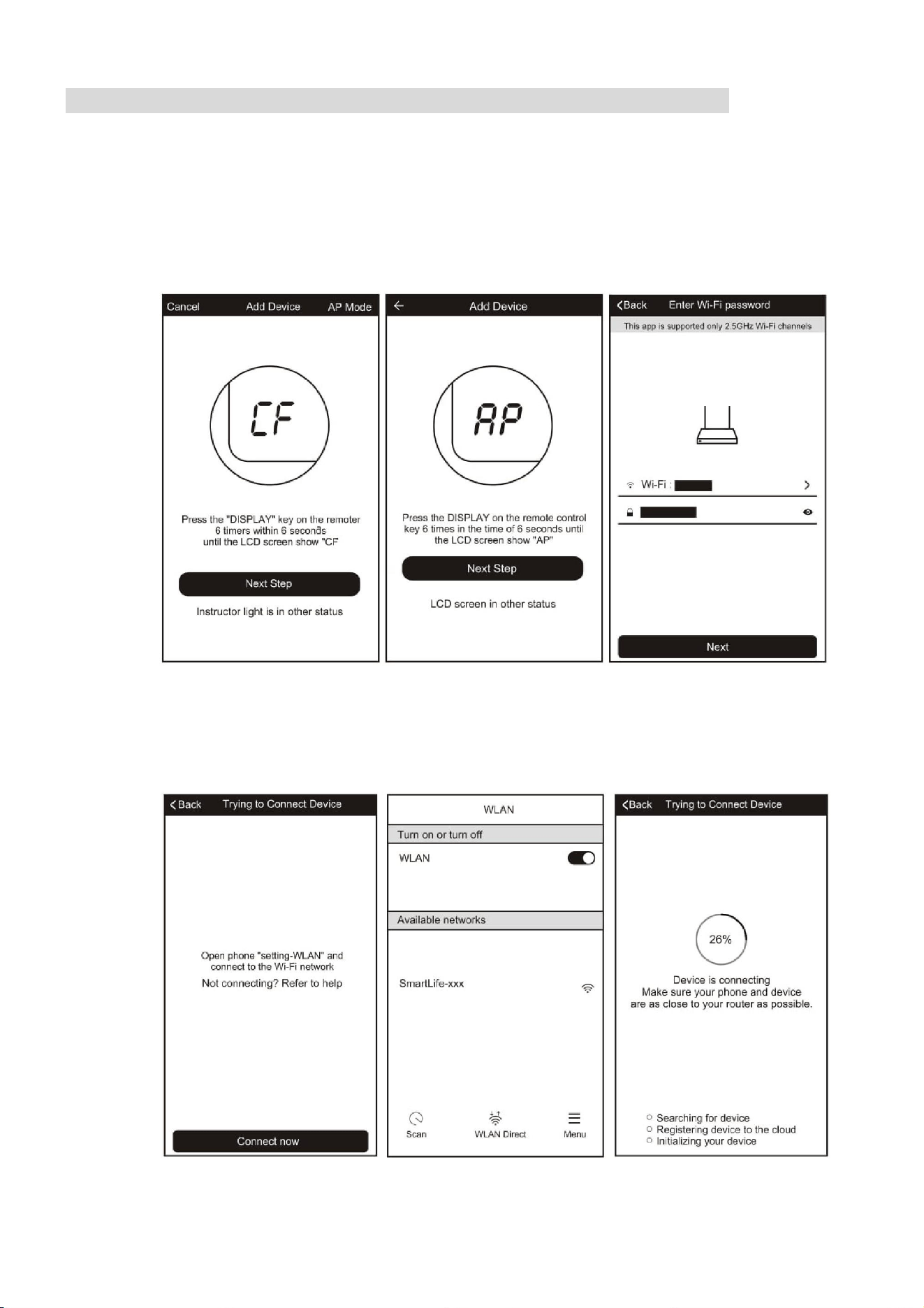
CONNECTING USING AP MODE (ALTERNATIVE METHOD)
1. Ensure that the screen on the air conditioner is displaying AP (otherwise to change the
connection mode: Quickly press the display button on the remote 6 times and wait 10
seconds until AP is displayed)
2. Press on the AP Mode button in the top right of the screen to change the app to AP mode
connection.
3. Select your Wifi router from the drop down list and enter the password (Please note the
password is case sensitive) before pressing next.
4. Connect your phone to the wifi network by leaving the app, and connecting to the Wifi
network created by the air conditioner “Smartlife-XXX”
5. Reopen the app and click on the “Connect now” button,
18
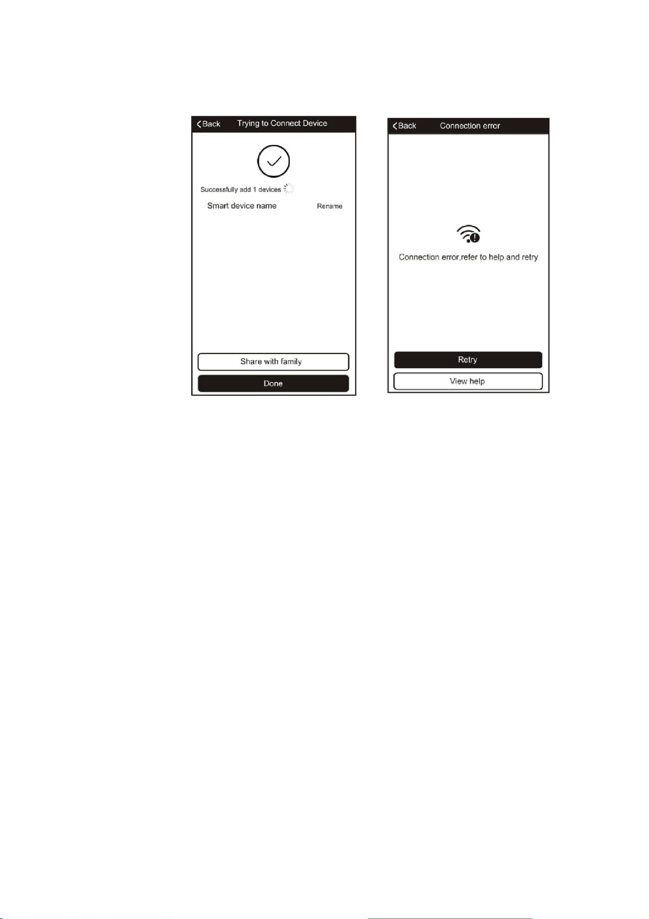
The app will automatically upload the connection information to the air conditioner, once the
connection is completed, a message will be displayed to confirm. On this page there is the
option to rename the air conditioner to something more relevant.
If the connection fails, please retry the connection, failing this try connecting using the CF mode
connection.
19
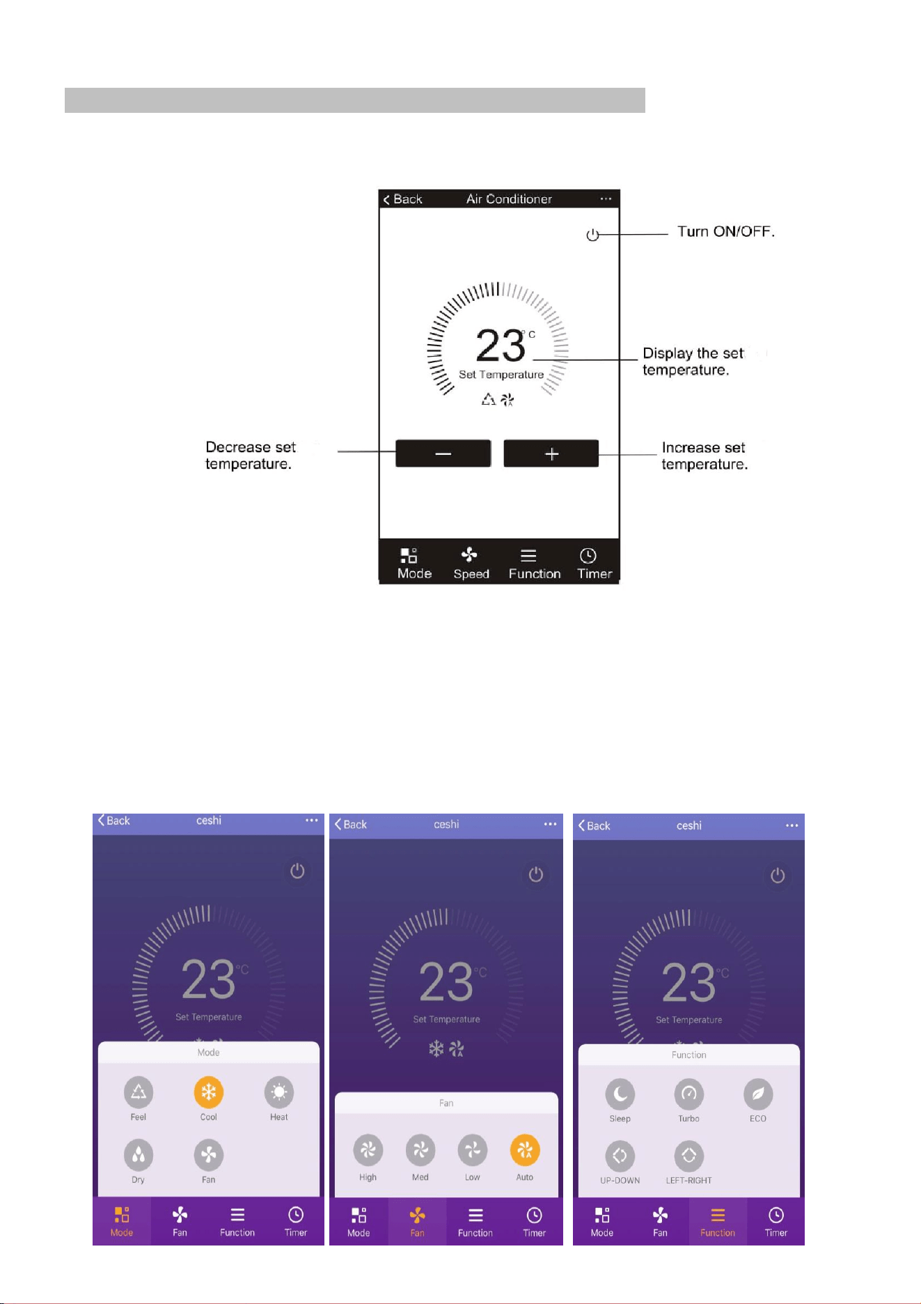
CONTROLLING YOUR DEVICE THROUGH THE APP
Now that your air conditioner is linked up to your network, you can control it from your phone.
Select your device in the device list to gain access to the controls for the device.
Use the + and – buttons to increase and decrease the desired temperature. The tabs on the
bottom of the screen should be used to change other settings.
Mode: Allows the operating mode to be changed between Feel, Heat, Dry, Cool and Fan.
Speed: Allows the fan speed to be changed between Auto, Low, Medium and High.
Function: Allows the Sleep, Turbo and Eco functions to be activated (See main manual for
description of the operation) and for vertical and horizontal swing on the louvres to be turned on
/ off (Not supported on all units)
20
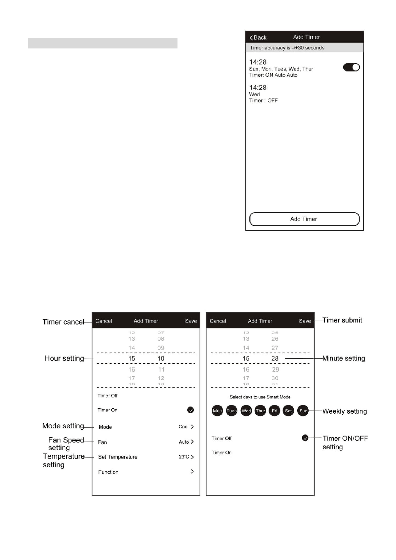
USING THE TIMER FUNCTION
The timer can be used to either set a time for the air
conditioner to turn on (and specify the settings it will run
with), or a time for the unit to turn off. Multiple timers can
be used together to build a schedule with on and off times.
1. Press the Timer button at the bottom right of the
screen.
2. To set a new timer, press the “Add Timer” button at
the bottom of the screen. If there is a timer already
programmed that you would like to amend, press
and hold the timer which requires amendment.
OFF TIMER:
1. Select Timer Off
2. Set the time the air conditioner should turn off 3.
Select which days the timer should operate
4. Press Save in the top right corner.
ON TIMER:
1. Select Timer On
2. Set the time the air conditioner should turn on
3. Select which days the unit should run on the auto timer.
4. Set the Mode, fan speed, desired temperature and function that the air conditioner
should run with.
5. Press Save in the top right corner.
21
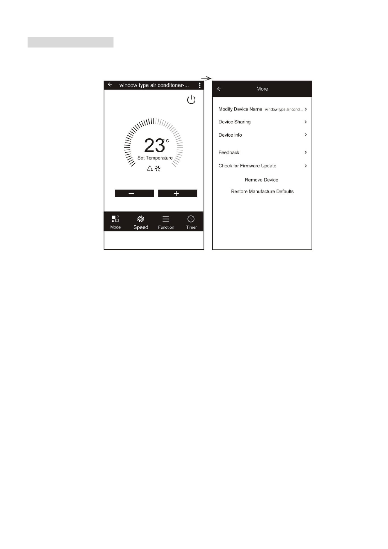
MORE SETTINGS
When on the main screen the three dots in the top right hand corner give you access to the
settings options for the app. This a number of extra options for modifying the name of the air
conditioner, and removing a device from the app.
22
MAINTENANCE
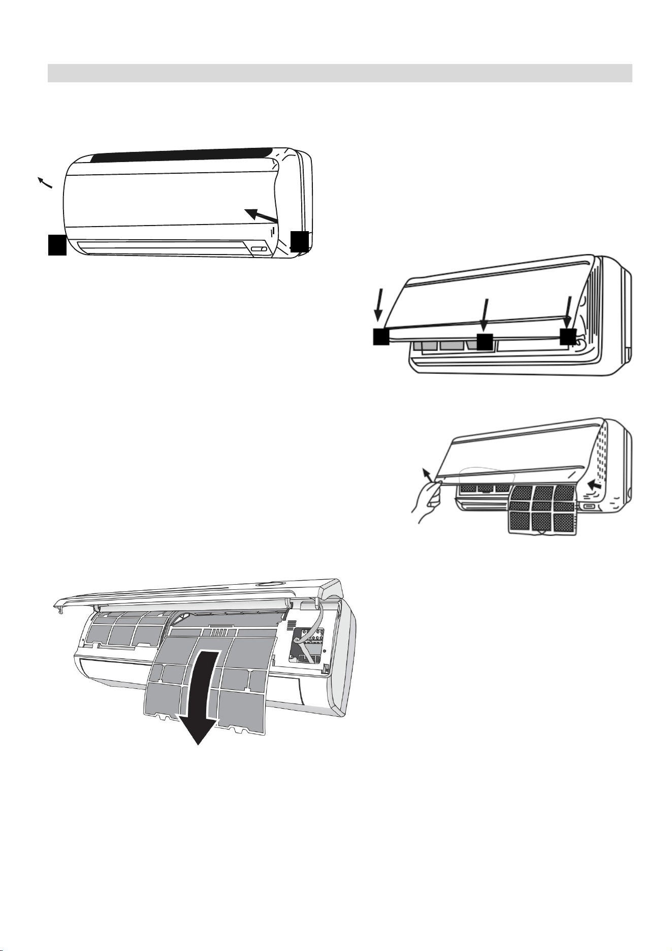
FILTERS
Ensure the power is turned off to the unit before attempting to service the filters.
OPENING THE FRONT PANEL: At the recesses,
pull the front part up with both hands. The front
panel will stay horizontal (at around 90°).
CLOSING THE FRONT PANEL: Press the front
part down at the sides and in the middle. Make sure
it is properly clicks into place.
REMOVING AND REPLACING THE FILTERS
1. Hold the front panel open (or put it in horizontal
position) and remove the filter(s).
2. Use a vacuum cleaner to remove dirt. If the dust
filter is very dirty, it may be washed in lukewarm
water with a very small amount of neutral detergent.
Rinse well and allow to dry completely (not in direct
sunlight or near a source of heat).
3. Keep the front panel open and
reinstall the filter(s). Press the
panel shut; a click indicates it is
closed properly.
4. Restore the power from the
consumer unit and turn the air
conditioner on.
INDOOR UNIT: While the unit is disconnected from power dust regularly with a dry cloth or
slightly damp paper towel. Never use chemicals or solvents. Never spray a liquid in or over the
appliance.
OUTDOOR UNIT: While the unit is disconnected from power. Remove dirt and keep the air
intake and exhaust openings free of debris, etc. Cleaning with chemicals may cause damage.
23
END OF SEASON
If the air conditioner is not going to be used for an extended period:
• Set in fan mode on a slightly warm day so that the inside of the appliance dries out.
• Switch off the power at the fuse box and remove the batteries from the remote control.
• Clean the filters.
• Remove the batteries from the remote control.
START OF SEASON
If the air conditioner is to be used again after an extended period:
• Check that the air intake and exhaust openings of the interior and exterior units are not
blocked. Remove any dirt or debris that has accumulated.
• Check that the filter is installed within the indoor unit and is clean.
• Check that the condensation outlet drains properly and there is no dirt or organic blockage
(otherwise leakage may occur)
• Install 2 AAA batteries in the remote control.
• Turn the appliance on, set the time and desired setting.
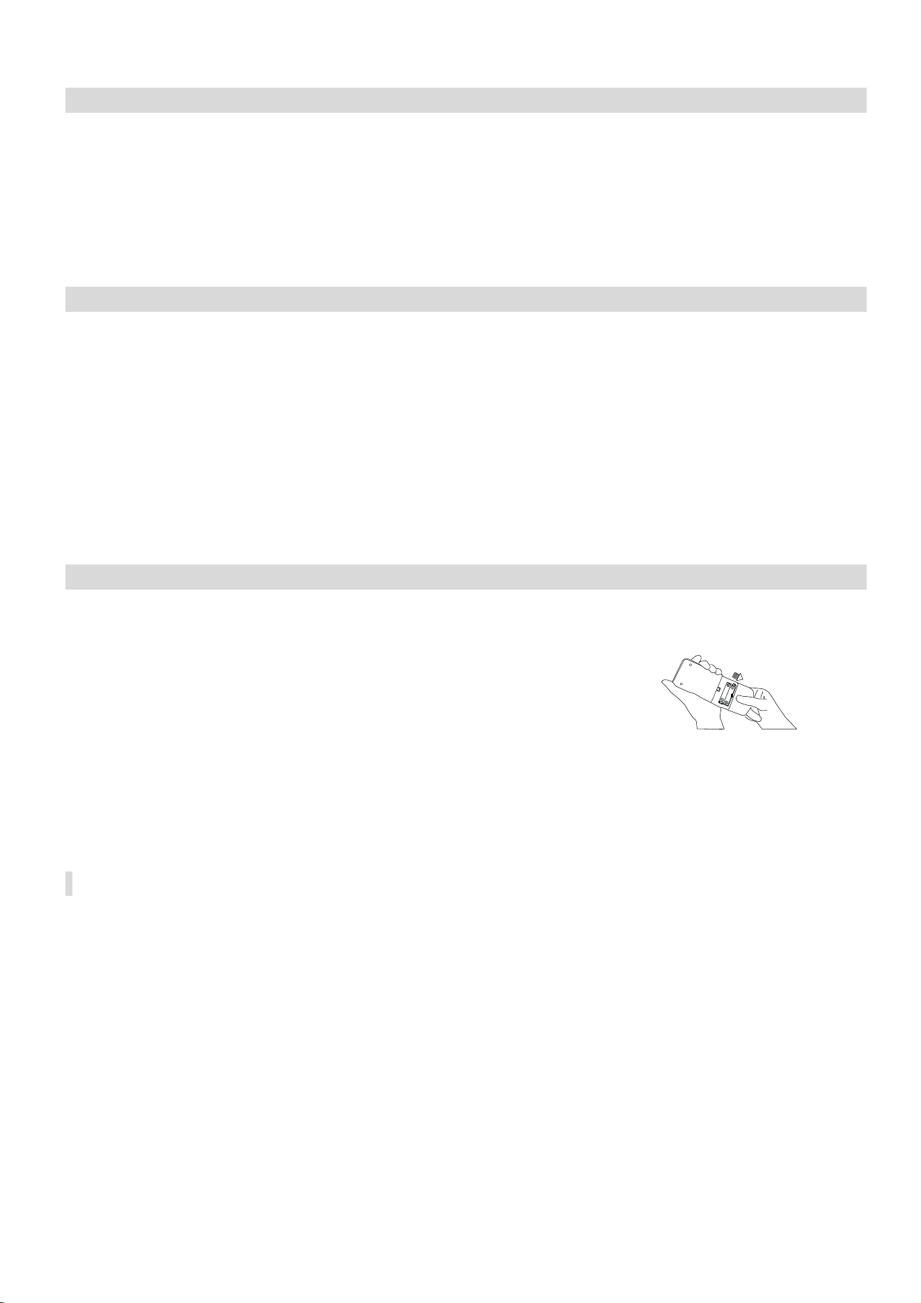
REPLACING THE BATTERIES
• Remove the cover from the rear of the remote control.
• Replace the AAA batteries, ensuring the correct polarity.
• Reinstall the cover on the rear of the remote control.
• The display on the remote will start to alternate between the
HEAT and COOL symbols. Press any button on the remote when
the HEAT symbol is displayed to set the remote up for heating and
cooling.
• If nothing is displayed on the remote, try pressing the power
button. If still no response, check the polarity of the batteries and
try replacing.

24
INSTALLATION GUIDE
SAFETY
• Only qualified personnel should install this appliance. This installation manual is
intended for use by individuals possessing adequate backgrounds and qualifications
in electrical, electronic, refrigerant and mechanical fields. Any attempt to install or
repair the appliance may result in personal injury and property damage.
• The manufacturer and retailer cannot be responsible for the interpretation of this
information, nor can it assume any liability in connection with its use.
• The units are designed for permanent installation.
• The equipment is designed for domestic or office use and we are not making any
endorsements for use in industrial or maritime environment.
• Do not place near sources of heat, vapors, industrial machine oil or other flammable
gases.
• High-frequency waves generated by radio equipment, welders and medical
equipment will interfere with the normal operation of the unit.
• Install this device only when it complies with local/national legislation, ordinances
and standards.
• Check the mains voltage and frequency. This unit is only suitable for an earthed
electrical supply, connection voltage 230 V~ / 50 Hz. The information, specifications
and parameter are subject to change due to technical modifications or improvement
without any prior notice. The accurate specifications are presented on the nameplate
label.
• Please read this installation manual completely before installing the product.
• When the power cord is damaged, replacement work shall be performed by
authorized personnel only.
• Installation work must be performed in accordance with all European, national and /
or local directives and standards and must be done by authorized personnel only.
• Always make sure to wear the correct personal safety protections such as protective
eyewear, gloves, ear protection etc.
• This air conditioner contains a refrigerant and can be classified as pressurized
equipment. Therefore always contact an authorized air conditioning engineer for
installation and maintenance of the air conditioner.
• The air conditioner must be inspected and serviced on an annual basis by an
authorised air conditioning engineer.
• Each indoor unit has a separate refrigerant circuit, and as such each circuit must be
individually pressure tested and purged during installation.

25
INDOOR UNIT POSITION
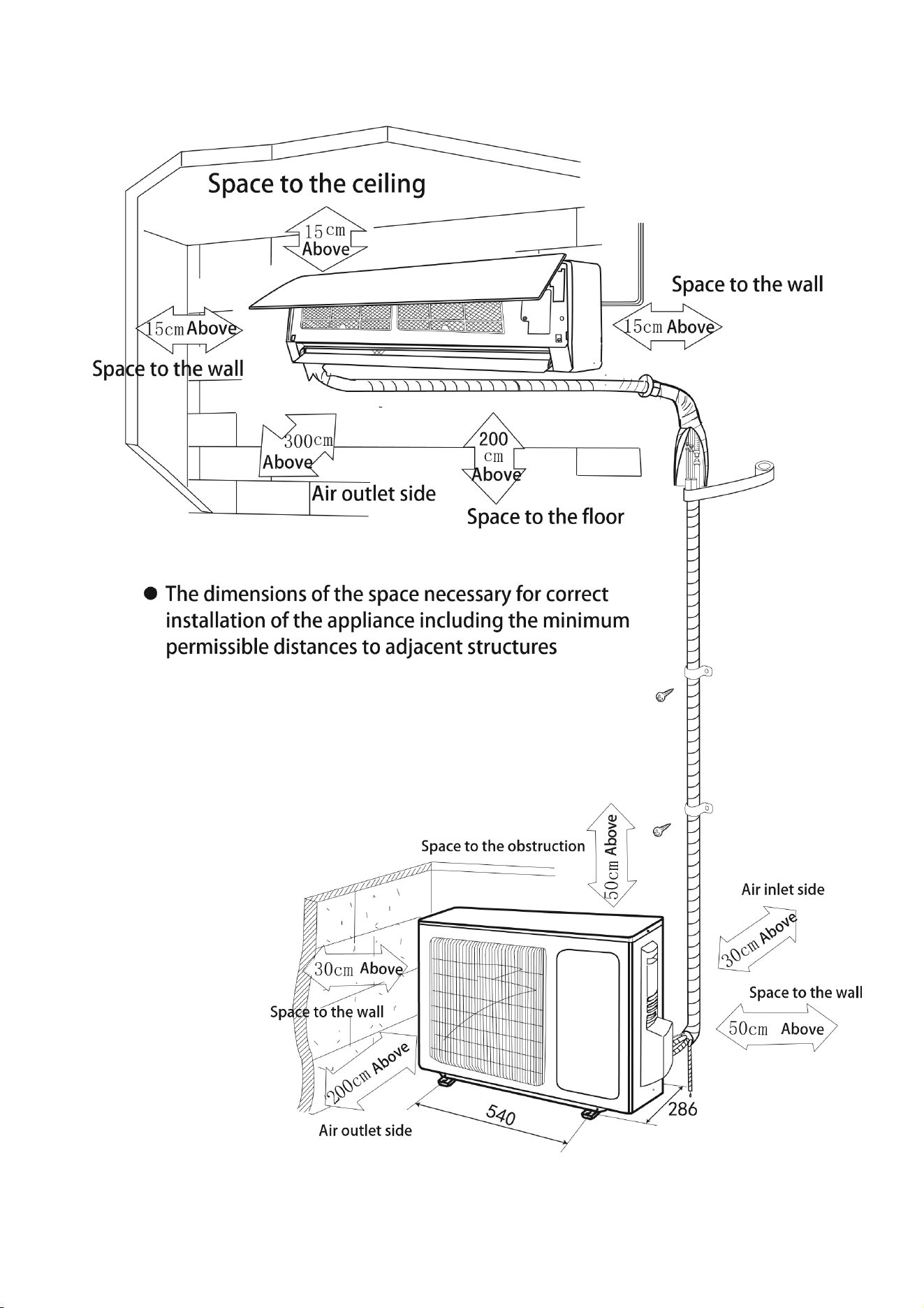
The air inlet and outlet vent should be away from any obstruction, ensuring that there is a good
airflow through the whole air-conditioned space. Select a position where the condensing water
can be easily drained out, and the indoor unit can be easily connected to outdoor unit. The wall
where the unit is fixed should be strong enough to withstand the full weight and vibration of the
unit. The unit should be accessible for service and maintenance. The height of the installed unit
should be ideally more than 200cm from the floor. The air conditioner must not be installed in a
wet environment such as a bathroom, shower or swimming pool etc.
OUTDOOR UNIT POSITION
A convenient position, dry and well ventilated, outside of direct sunlight or strong winds, which is
not on a flood line and where noise and airflow does not cause interference or inconvenience.
Select a location where there are no obstructions to the inlet and outlet vents. The location
should be able to withstand the full weight and vibration of the outdoor unit and permit safe
installation.
Make sure that the outdoor unit is installed in compliance with the installation dimension diagram
with easy maintenance access. Select a place where it is out of reach of children. Do not block
utilities access or fire escapes.
The external unit must be lifted and put in place by two people.
NOTES:
1. Only use a power supply with the correct ratings, making sure the correct sized power cables
are used
2. The appliance shall be installed in accordance with standard wiring regulations by qualified
personnel
3. Only replace fuses according to their printed rating or corresponding pcb boards.
26
RECOMMENDED INSTALLATION SPACING DIAGRAM
27
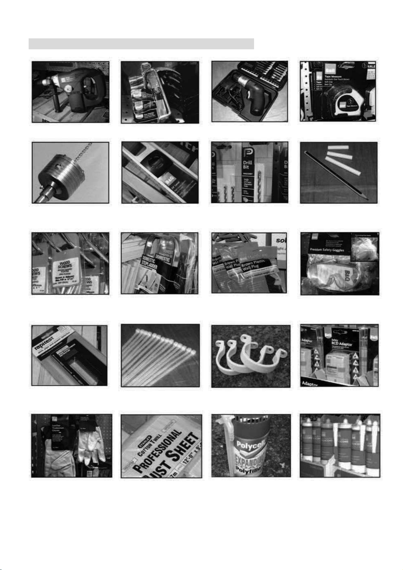
TOOLS RECOMMENDED FOR INSTALLATION
Electric Drill
Hammer
Screwdrivers
Tape Measure
Core Hole Cutter
Spirit Level
Number 14 (7mm)
Masonry Drill
Pencil and Chalk
1.5 inch number 10
screws
Small Stepladder
7mm Wall Plugs
Protective Glasses
and Mask
Pipe and Cable
Detector
4 inch Plastic Ties
2 Inch Pipe Clips
Circuit Breaker
Garden Gloves
(For Handling
Outdoor Unit)
Dust Sheets
Foam Filler
Silicone Sealant
and gun
28
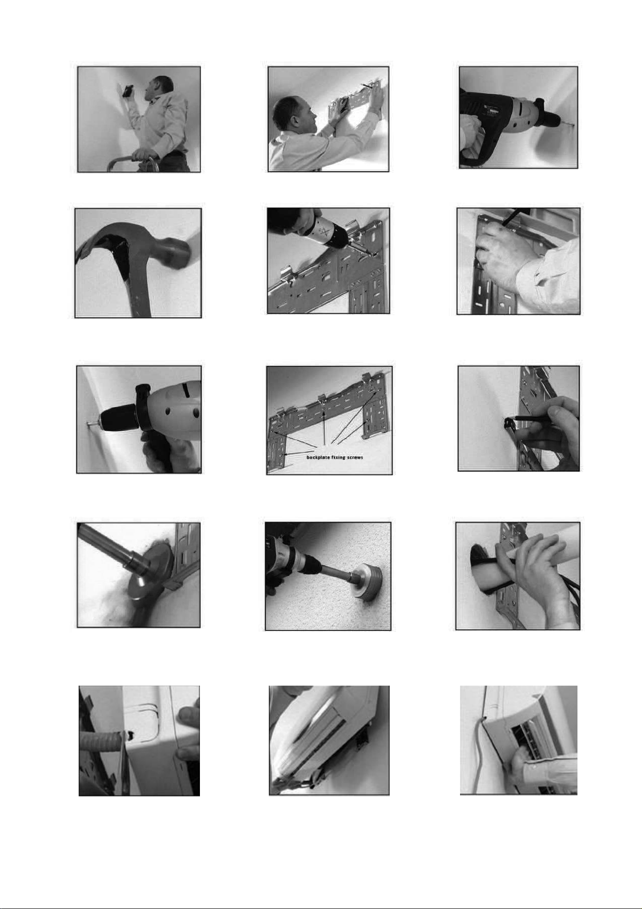
1. Check the area for any hidden
wires or pipes.
2. Mark the right hand backplate
screw position.
3. Remove the backplate and drill a
7mm hole.
4. Tap a 7mm wall plug into position.
5. Screw the backplate to the wall
using 1.5 inch number 10 screws.
6. Check to ensure level, then mark
the other holes and swing the
backplate away.
7. Drill the rest of the holes and
insert the wall plugs.
8. Fix the backplate to the wall.
9. Mark the hole centre and make
sure the cutter will clear the
backplate.
10. Drill the hole at a slight
downwards angle. When you feel
the pilot drill exit the outside wall
stop.
11. Finish the hole from the outside
to keep it clean.
12. Feed the cord and drain hose
carefully through the wall.
13. Undo the power lead and break
out the plastic tab.
14. Hook the indoor unit onto the top
of the backplate.
15. Lock the bottom of the unit onto
the base of the backplate.
29
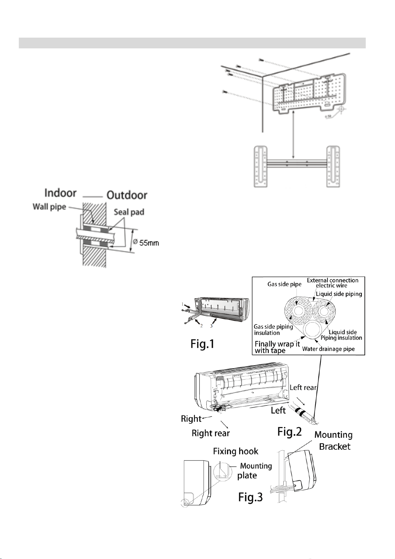
INFORMATION REGARDING THE INSTALLATION OF THE INDOOR UNIT
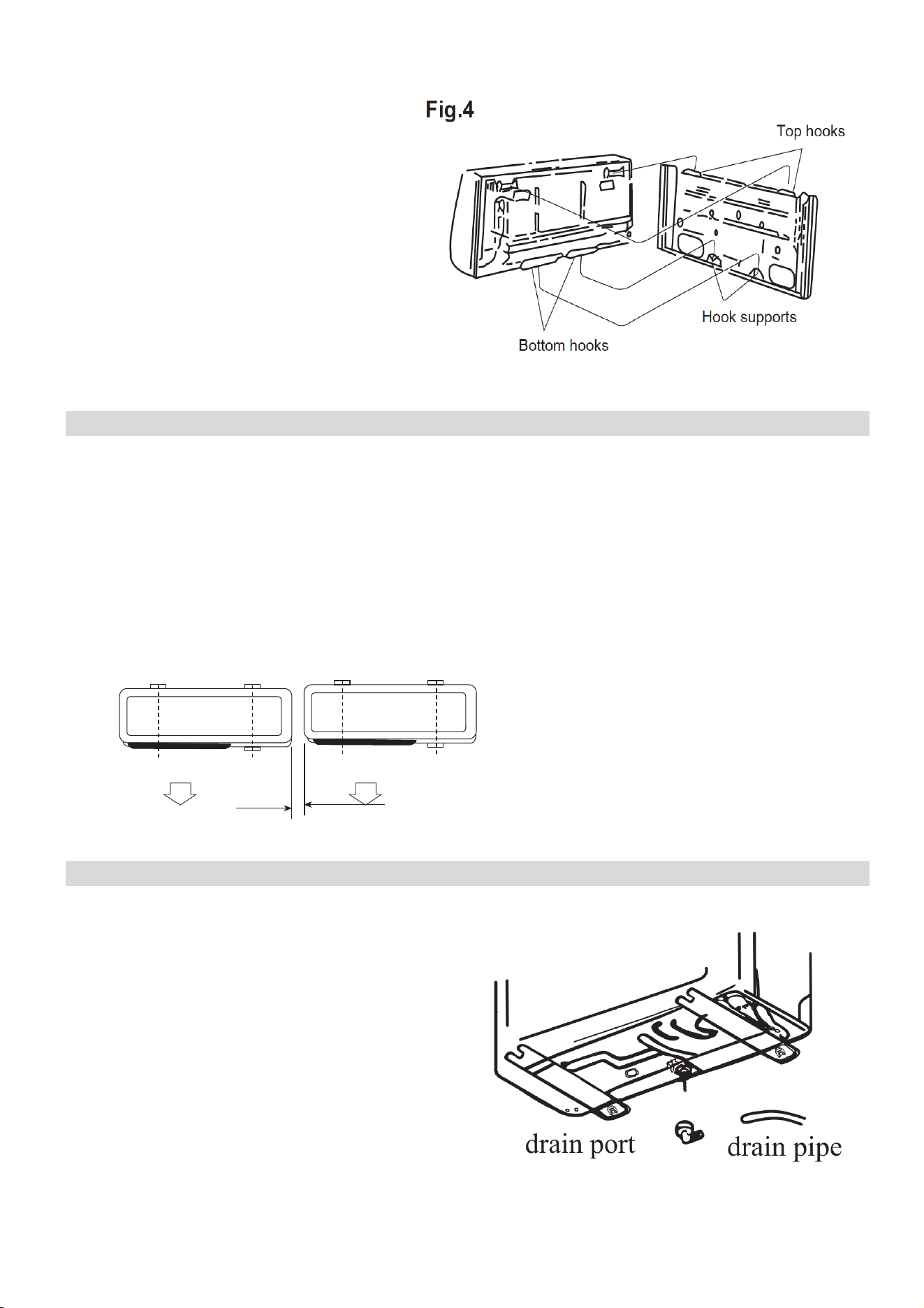
INSTALLING THE REAR PANEL
1. Always mount the rear panel horizontally.
Due to the water tray within the indoor unit
we would advise that the outlet of the water
tray should be fractionally lower when
installing as this will aid drainage of the
condensate collected.
2. Fix the rear panel on the wall with screws.
3. Be sure that the rear panel has been fixed
firmly enough to withstand the weight of an
adult (60Kg), furthermore the weight should
be evenly shared by each screw.
INSTALLING THE PIPING HOLE
1. Make the piping hole (55mm diameter) in the wall at
a slight downward slant to the outdoor side (To aid
drainage of the condensate).
2. Insert the piping-hole sleeve into the hole to prevent
the connecting piping and wiring from been damaged
when passing through the hole.
The piping can be lead out on the right,
left or directly behind the indoor unit as
seen in fig. 1. Please cut off the pipe hole
guards if you are changing the pipe
position. The unit also features
alternative guards for more pipe
positioning.
Make sure that the drain pipe is
underneath the pipelines. (Fig.3) (When
the drain pipe passes the room interior,
some condensed water might occur to its
surfaces if the humidity is very high).
Tidy up the copper pipes, electrical
cables and water drains and pass them
through the wall hole drilled earlier (fig.2).
Hang the mounting slots of the indoor
unit on the wall mounting bracket making
sure is tight in place (fig.3) so that the
hooks at the bottom of the indoor unit
match the hooks of the wall mounting
bracket (fig.4)
30
Notes:
1. The height of the installed unit is
recommended to be > 200 cm.
2.
Either the indoor unit or the outdoor
unit can be higher, but the height
difference must comply with a max.
5 metres level difference.
3. Try to avoid bending the pipes as
much as possible so as to avoid
possible negative impacts upon the
performances of the unit.
INSTALLATION OF THE OUTDOOR UNIT
Try to move the product to the installation location in its original packaging
As the gravity center of the unit is not at the installation center, special caution should be taken
when using hoisting cables to lift it up
During transport, the outdoor unit must not be tilted to over 45 degrees (also do not store the unit
horizontally.
Use expansion bolts to fix the mounting supports on the wall;
Use bolts and nuts to fix the outdoor unit firmly on the supports and keep on the same level;
If the unit is installed on the wall or at the rooftop, the supports have to be firmly fixed so as to
resist earthquakes or strong wind.
Dimensions for parallel units installations
300mm(1')min
CONDENSATE DRAINAGE OF THE OUTDOOR UNIT
When operating in heating mode condensate
will collect and drain through the base of the
outdoor unit. The air conditioner is supplied with
an elbow joint which can be connected to the
underside of the outdoor unit for drainage.
1. Connect the elbow joint to the drainage
hole on the underside of the outdoor unit.
2. Connect a drain hose (not supplied) to the
elbow joint and run downhill to your chosen
drainage point.
Please note: The drainage is gravity fed, and so
must run downhill.
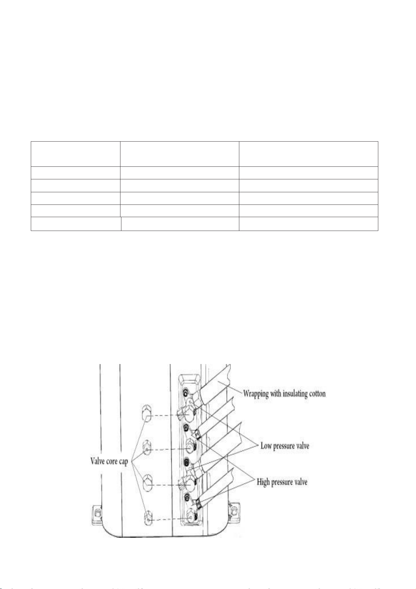
31
STANDARD PIPELINES CONNECTION & AIR PURGING
No dust or any other particles, air or moisture should be allowed to enter the air conditioning
system. Careful attention should be paid when pipeline connection for outdoor unit is made. Try
to avoid repeated curves as much as possible; otherwise damage to the copper pipes may occur.
Suitable wrenches should be used when the pipeline connection is done so as to ensure
appropriate torque (refer to following torque table).
Excessive torque action might damage the joints while too little torque might lead to leakage.
Torque based upon the wrench to be used
If you are installing a multisplit system with easy fit connectors follow the procedures below:
1. Remove the dust caps from the indoor and outdoor units and the connecting pipe.
2. Align the joint of the connecting pipe between the indoor and outdoor and tighten the
connecting nut by hand to prevent cross threading. Secure them with a wrench, applying
the maximum torque as shown in the table above.
3. Pressure test and vacuum pump the pipework for each refrigerant circuit.
4. Remove the two valve core caps from the outdoor unit and turn on the high and low
pressure valve cores with an socket wrench, then tighten the two valve core caps of the
outdoor unit. Finally you can wrap hot insulating tape around the joints of indoor and
outdoor units
Copper pipe diam.
Tightening torque
Strengthened tightening torque
6.35(1/4")
160kgf.cm(63kgf.inch)
200kgf.cm(79kgf.inch)
9.52(3/8")
300kgf.cm(118kgf.inch)
350kgf.cm(138kgf.inch)
12.7(1/2")
500kgf.cm(197kgf.inch)
550kgf.cm(216kgf.inch)
15.88(5/8")
750kgf.cm(295kgf.inch)
800kgf.cm(315kgf.inch)
19.05(3/4")
1200kgf.cm(472kgf.inch)
1400kgf.cm(551kgf.inch)
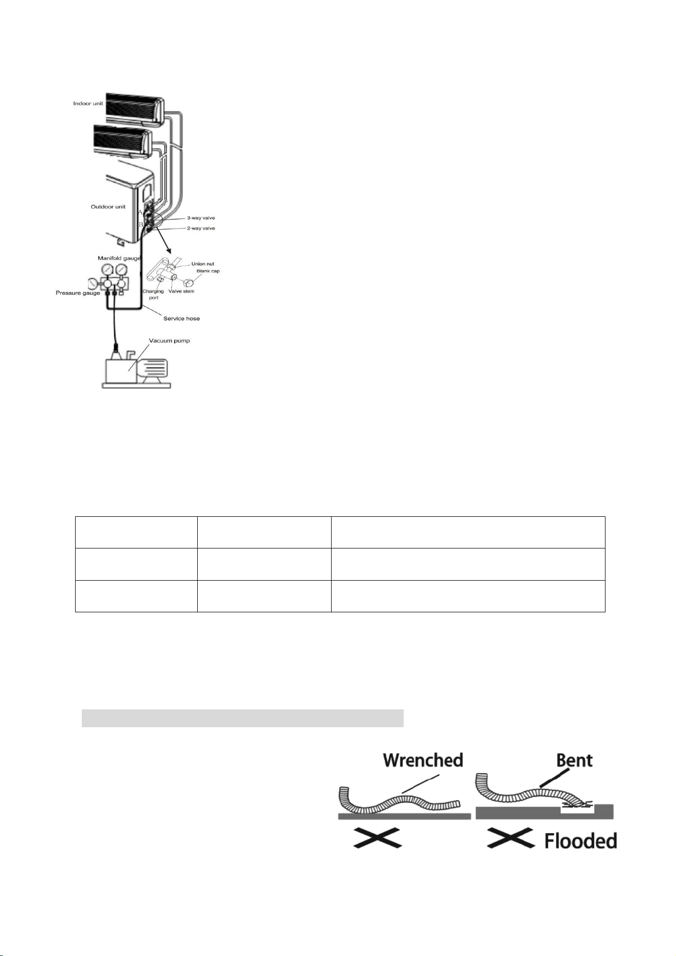
32
AIR PURGING WITH VACUUM PUMP
Please note this should be completed for each refrigerant
circuit (each indoor unit)
1. Check that pipelines connection have been properly
connected, remove the charging port cap, and connect the
manifold gauge and the vacuum pump to the charging
valve using service hoses as shown
2. Open the valve on the low-pressure side of the manifold
gauge, then run the vacuum pump. Vacuum the indoor unit
and the connecting pipes until the pressure in them lowers
to below 1.5mmHG (The operation time for vacuuming is
about 10 minutes). When the desired vacuum is reached,
close the low pressure valve on the manifold and stop the
vacuum pump.
3. Disconnect the service hoses and fit the cap to the
charging valve.
4. Remove the blank caps, and fully opens the spindles of the
2-way and 3-ways valves with a service valve wrench.
5. Tighten the blank caps of the 2-way and 3-ways valves,
applying the torque listed in the table above.
ADDING REFRIGERANT
Refrigerant must be added if the pipe length is more than 5 metres (16'5"). This
operation can only be performed by a professional F-Gas engineer, for the additional
gas amount, see the below
Liquid pipe
diameter
Additional
Refrigerant
Additional Refrigerant
Φ6.3 or Φ6 (1/4)
15g per each meter
added
Total length of pipe run – 5 meters) x 15 g
Φ9.52 or Φ9 (3/8)
25g per each meter
added
Total length of pipe run – 5 meters) x 25 g
GAS LEAKAGE INSPECTION
After the pipeline connection is done, use a leakage inspection device to carefully check
if there is any leakage at the joints. This is an important step to ensure the quality of
installation. Once a leak is detected, proper action should be taken immediately.
INSTALL THE WATER DRAINAGE PIPE
1. For good drainage, the drain
hose should be angled
downwards.
2. Do not pull on or bend the drain
hose or flood its end with water.
3. When the long drainage hose
passes through indoor areas, it
should be wrapped in insulation.
33
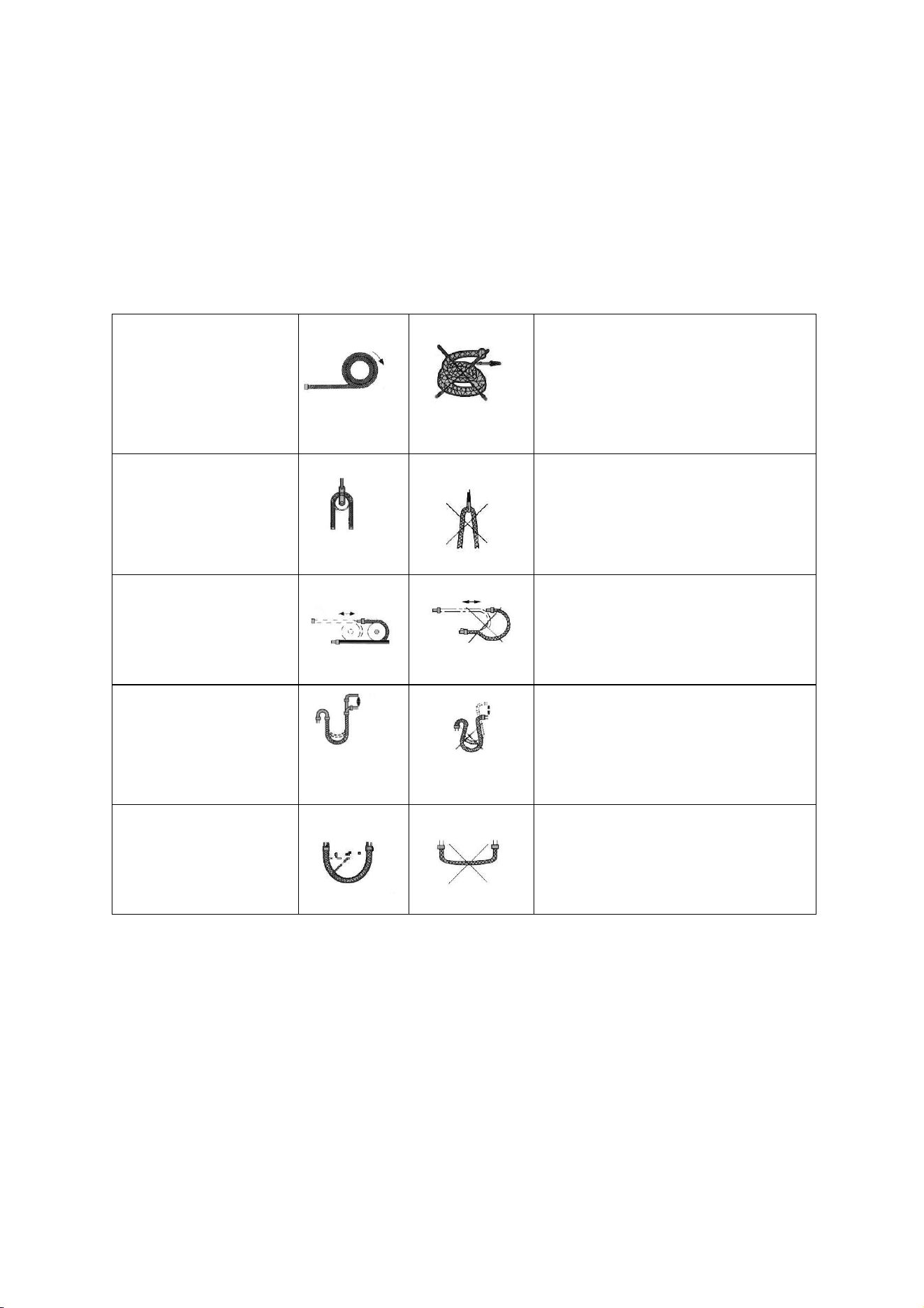
NOTES:
The copper pipe used in the refrigeration lines are very soft, high pressure copper and
prone to get damaged if not handled correctly. Try to avoid bending or stretching the
pipework. Always ensure the pipes are protected when running through the wall to help
prevent damage to the pipes.
To keep the allowed
bending radius please
make the packed soft
pipes vertical
before extending
Please do not extend only one
side of the packed soft pipes.
Please make use of
semicircle pulley to
keep the allowed
bending angle
Extreme bending could damage
the pipes
Please use a twisting
wheel to avoid
improper bending.
Over bent soft pipes will lead to
irregular bending
Please use rigid
elbow to keep the
bending angle while
soft pipes operating.
Undersize bending will damage
the soft pipe.
Please keep the
minimum bending
angle while installing
Do not use short sharp angle
bends.
34
ELECTRICAL CONNECTION OF THE AIR CONDITIONER
• The electrical connections can be found under the protective plastic cover. Remove
this from the side of the outdoor unit to gain access to the electrical connections.
• Connect the indoor power and control wires with the matching outdoor wire as per
the electrical diagram.
• Do not attempt to connect the wires in a different way to the diagram on the air
conditioner as this could damage the unit and invalidate the warranty.
• Secure the wires and replace the cover before operating the unit.
• The appliance should be installed in accordance with national wiring regulations.
• If the supply cord is damaged, it must be replaced by the manufacturer, its service
agent or a suitably qualified person in order to avoid a hazard.
• The unit is designed to be hard wired and a suitable switch with a contact separation
of at least 3mm in all poles must be added to the fixed wiring.
• The air conditioner electrical wiring must follow the specific country regulations. If
power cord is damaged must be replace by a qualified electrician.
35
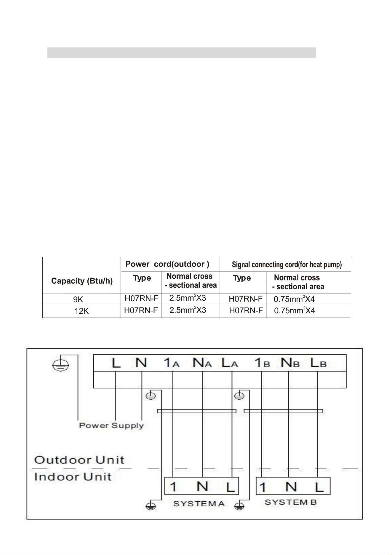
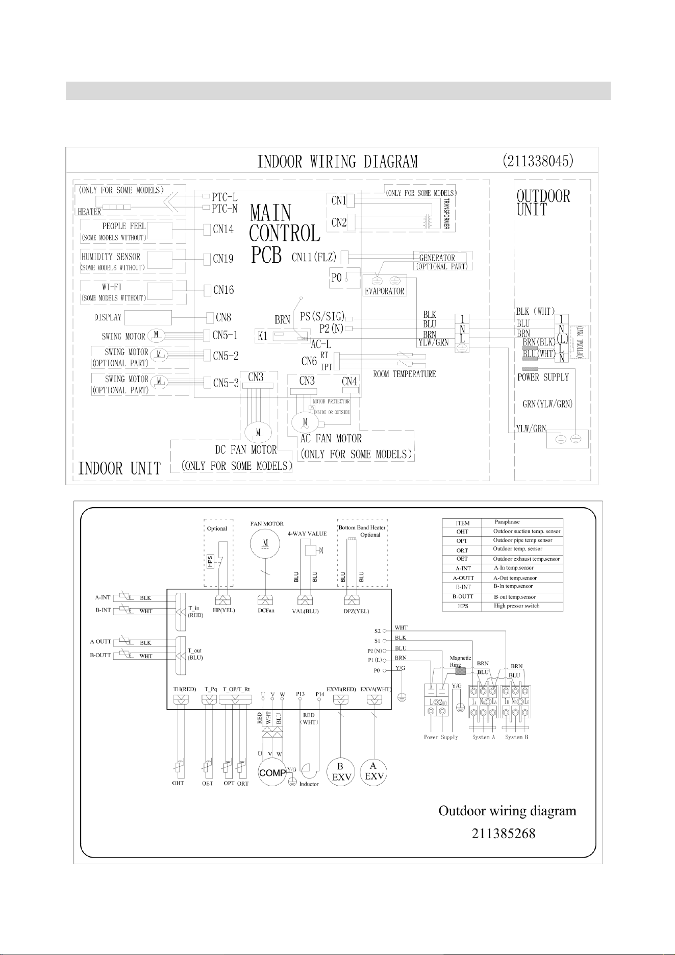
ELECTRICAL WIRING DIAGRAMS
Please note: The diagrams provided in the manual are for guidance only. Due to continual
product development the diagrams provided on the units themselves should be followed
where any discrepancies are found
Outdoor PCB
36
TROUBLESHOOTING AND SELF DIAGNOSIS
MALFUNCTION
POSSIBLE CAUSE
The appliance
does not
operate
Power failure
Damaged indoor/outdoor unit fan motor
Faulty compressor thermomagnetic circuit breaker
Faulty protective device or fuses
Loose connections
Self protection in adverse conditions
Voltage higher / lower than the voltage range
Active TIMER-ON function
Damaged electronic control board
Strange odour
Air filter dirty
Noise of running
water
Back flow of liquid in the refrigerant circulation
A fine mist
comes from
the air outlet
This occurs when the air in the room becomes very cold, for example
in the COOLING or DEHUMIDIFYING modes.
A strange noise
can be heard
This noise is made by the expansion or contraction of the front panel
due to variations in temperature and does not indicate a problem.
Insufficient
airflow, either
hot or cold
Inappropriate temperature setting.
Air inlet or outlet of indoor or outdoor unit has been blocked.
Air filter is blocked.
Fan speed set at minimum.
Other sources of heat in the room.
No refrigerant.
The appliance
does not
respond to
commands
Remote control is not near enough to indoor unit.
Battery in Remote controller may have been exhausted..
Obstacles between remote control and signal receiver in indoor unit.
The display is
off
Active LED function
Power failure
Remote cannot
select heating
mode.
Remove the batteries from the remote and follow the guide for
setting up the remote.
Switch off the air conditioner immediately and cut off the power supply in the
event of:
Strange noises during operation.
Faulty electronic control board
Faulty fuses or switches.
Spraying water or objects inside the appliance.
Overheated cables.
Very strong smells coming from the appliance.
37
ERROR SIGNALS ON THE DISPLAY
In case of error, the display on the indoor unit shown the following error codes:
Error Code
Failure type
E0
Indoor and outdoor communication failure
EC
Outdoor communication failure
E1
Indoor room temperature sensor
E2
Indoor coil temperature sensor
E3
Outdoor coil temperature sensor
E4
System abnormity
E5
Model configuration wrong
E6
Indoor fan motor fault
E7
Outdoor temperature sensor
E8
Exhaust temp. sensor
E9
IPM drive and module fault
EA
Current sensor fault
Ed
Indoor EEPROM fault
EC
Outdoor Communication fault
EE
Outdoor EEPROM fault
EF
Outdoor fan motor fault (DC motor)
EH
Outdoor suction temperature sensor fault
En
Outdoor gas pipe temperature sensor fault
EP
Temp. switch fault ( on top of the compressor)
EU
Voltage sensor fault
Ey
Outdoor liquid pipe temperature sensor fault
Protection Display Code List
PA
Indoor run mode conflict
P1
Overvoltage /lower voltage protection
P2
Overcurrent protection
P4
Exhaust over temperature protection
P5
Too cool protection in cooling mode
P6
Overheat protection in cooling mode
P7
Overheat protection in heating mode
P8
Outdoor over temperature
/ lower temperature protection
P9
Drive protection (software control )
P0
Module protection (hardware control)
38
OUTDOOR UNIT FAULT CODES
The outdoor unit has an LED on the power board. This LED will be illuminated when
the compressor is running and blink 1s on and 1s off when the compressor is in
standby. If there is a fault on the outdoor unit, it will blink on and off for half a second at
a time, followed by a 3s gap. The number of consecutive blinks will show the fault as
per the table below:
No. of blinks
Fault
1
IPM protection
2
Over voltage /lower voltage
3
Overcurrent
4
Exhaust over temperature protection
5
Outdoor coil over temperature protection
6
Drive fault and protection (V1,VP1)
7
Communication fault with indoor unit
8
Compressor overheat fault (compressor top switch)
9
Short-circuit / open-circuit fault of outdoor temperature sensor
10
Short circuit / open-circuit fault of outdoor heat exchanger temperature
sensor
11
Short-circuit / open-circuit fault of exhaust temperature sensor
12
Voltage sensor fault
13
Current sensor fault
14
IPM fault
15
Communication fault between power source board and IPM
16
No feedback from DC fan motor(outdoor unit)
17
Defrost state
39
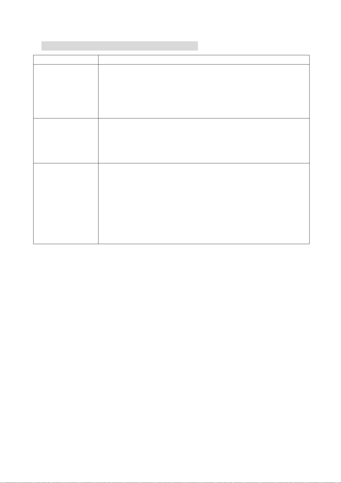
WIFI CONTROL TROUBLESHOOTING
Description
Possible Cause
Air conditioner
can’t be configured
successfully
1. Check the mobile device is connected to WIFI
2. Check the AC is connected
3. Check that any firewall or other restrictions are causing
problems
4. Check the router is functioning normally
5. Check that the router isn’t blocking the App
Mobile device can’t
control the air
conditioner
The app displays “Identification failed”. This indicates that the AC
has been reset and the mobile device has lost contact with the AC.
Reconnect the device following the above instructions. If this fails,
delete the AC from your devices list and start the install process
from the beginning.
Mobile device can’t
find AC
The app displays “Air conditioner out of line”. Check the below:
1. The AC has been reconfigured
2. The AC is not receiving power
3. The router is not powered on
4. The AC can’t connect to router
5. The AC can’t connect to network through the router
6. The mobile device can’t connect to the router
7. The mobile device can’t connect to a network (when being
used remotely)
40
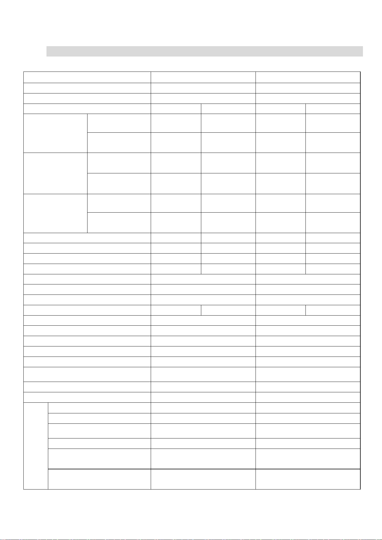
TECHNICAL SPECIFICATION
Model
iQool-2MS9K9K(B)
iQool-2MS12K12K(B)
Rated voltage and frequency (Ph-V-Hz)
1Ph/220-240V~/50Hz
1Ph/220-240V~/50Hz
Fuse Required
13A
13A
Mode
Cooling
Heating
Cooling
Heating
Rated capacity (W)
Single
2600
2600
3200
3200
Double
5200
(1230~5600)
5290
(1290~5750)
5200
(1230~5600)
5290
(1290~5750)
Power input (W)
Single
740
710
910
870
Double
1480
(280~1650)
1418
(250~1700)
1480
(280~1650)
1418
(250~1700)
Current input (A)
Single
3.42
3.30
4.23
4.04
Double
6.8
(1.3~7.6)
6.5
(1.2~7.8)
6.8
(1.3~7.6)
6.5
(1.2~7.8)
SEER/SCOP(W/W)
6.2/A++
4.0/A+
6.2/A++
4.0/A+
Nominal load (kW)
5.20
5.29
5.20
5.29
Balance point temperature heating (
o
C)
/
-7
/
-7
Min. outdoor operating temperature (
o
C)
/
-15
/
-15
Thermostat-off mode (W)
15
15
Standby mode (W)
2
2
Off mode (W)
0
0
Annual consumption (kW)
294
1540
294
1540
Copper Pipe Type length
5m
5m
Liquid side / Gas side (mm/inch)
6.35 (1/4) + 9.52 (3/8)
6.35 (1/4) + 9.52 (3/8)
Max. refrigerant pipe length for each unit
15m
15m
Max. elevation
10m
10m
Interconnecting Cable
4×0.75mm²
4×0.75mm²
Fuse Rating
5A on indoor PCB
5A on indoor PCB
Moisture Removal (L/h)
0.9 L/h per unit
0.9 L/h per unit
Built In Ioniser
No
No
Indoor
Air Flow (m
3
/h)
550
550
Dimensions (W*D*H) (mm)
777 x 201 x 250
777 x 201 x 250
Packaging (W*D*H) (mm)
840 x 260 x 315
840 x 260 x 315
Net / Gross weight (Kg)
8 /10.5
8 /10.5
Noise – Sound pressure level
(dB/A)
24~40
24~40
Noise – Sound power level
(dB/A)
34~50
34~50
41
Outdoor
Dimension (W*D*H) (mm)
835 x 360 x 605
835 x 360 x 605
Packaging (W*D*H) (mm)
883 x 394 x 645
883 x 394 x 645
Net / Gross Weight (Kg)
34 / 38
34 / 38
Noise – Sound pressure level
(dB/A)
55
55
Noise – Sound power level
(dB/A)
65
65
Refrigerant type/weight
R32/1100g
R32/1100g
Defrost mode
Automatic defrosting
Automatic defrosting
Applicable climate types
Cooling (0
o
C – 53
o
C)
Heating(-20
o
C – 30
o
C)
Cooling (0
o
C – 53
o
C)
Heating(-20
o
C – 30
o
C)
Due to continuous product development process specification may change.
These units contain a gas governed by F-Gas regulations. The gas must be
handled by qualified F-Gas engineers.
APPENDIX
Disposal: Do not dispose this product as unsorted municipal waste. Collection
of such waste must be handled separately as special treatment is necessary.
Recycling facilities are now available for all customers at which you can
deposit your old electrical products. Customers will be able to take any old
electrical equipment to participating sites run by their local councils. Please
remember that this equipment will be further handled during the recycling
process, so please be considerate when depositing your equipment. Please
contact the local council for details of your local household waste recycling
centres.
42
WARRANTY INFORMATION
electriQ guarantee provides cover against material or manufacturing faults.
This means that if your air conditioner develops a fault during the guarantee
period, we will arrange for it to be repaired or replaced.
Faults arising from a faulty installation are specifically excluded.
The system must be serviced annually by qualified personnel.
This unit must be operated under conditions as recommended in this user
manual, at voltages indicated on the unit. Any attempts made to service or modify
the unit by unqualified person, will render this WARRANTY VOID.
This warranty is in addition to, and does not affect, your statutory rights.
Our warranty is RTB warranty and cover parts and labour only.
We recommend that you note the details of your purchase below and retain your original
proof of purchase receipt with this manual. Keep these documents safe in the event of a
warranty claim.
Purchase Date: _____________________________
Retailer name: _____________________________
Model number: _____________________________
Serial number: _____________________________
Installation Date: _____________________________
Installer name: _____________________________
Service Date: _____________________________
Engineer/ Company name: _____________________________
electriQ UK SUPPORT
www.electriQ.co.uk/support
Please, for your own convenience, check the troubleshooting guide before calling the
service line.
If the unit still fails to operate call: 0330 390 3061 or complete the online form
Office hours: 9AM - 5PM Monday to Friday
www.electriQ.co.uk
Unit J6, Lowfields Way
Elland, West Yorkshire
HX5 9DA