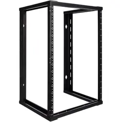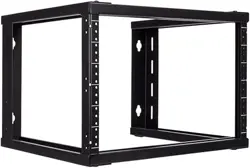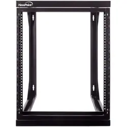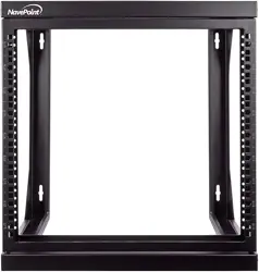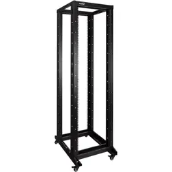
4-Post Open Frame Rack with Casters
www.NavePoint.com
© 2017 NavePoint, LLC
Rev. 201708
Thank you for purchasing a NavePoint product. NavePoint intends this manual to guide you through
a smooth installation of the product. NavePoint assumes that you are qualied in the servicing of
computer equipment and trained in recognizing any hazards that may occur in the installation of this
product. If you have any questions regarding the installation or use of your product, please call us at
888.505.1363.
Instructions for Products:
00301007 - 22U
00301008 - 42U
00301104 - 42U
00301105 - 22U
00301106 - 42U
00301107 - 22U
Equipment Mounting
Hardware
00301007/22U, 00301105/22U,
00301107/22U
M6 Cage Nut, Screws and Plastic Washers x 20
00301008/42U, 00301104/42U,
00301106/42U
M6 Cage Nut, Screws and Plastic Washers x 40
Important information-
Keep this information for further reference.
WARNING
Limitations of Liability: In no event will NavePoint, LLC. (or its ofcers, direc-
tors, employees or agents) be liable for any damages, whether direct or
indirect, special, punitive, incidental or consequential damages (including,
but not limited to, lost prots or revenue, loss of use, lost business opportu-
nities or loss of goodwill) or for the costs of procuring substitute products,
arising out of or in connection with the use of the product, whether such
liability arises from any claim based upon contract, warranty, tort (including
negligence), product liability or otherwise, whether or not seller has been
advised of the possibility of such loss or damage. In no event will seller’s
total cumulative liability, from all causes of action and all theories of liabil-
ity, exceed the total amounts actually paid to seller by customer under the
order that gives rise to any liability hereunder.
The information contained in this document is subject to change
without notice.
NavePoint makes no warranty of any kind with regard to this
material, including, but not limited to the implied warranties of
merchantability and tness for a particular purpose.
NavePoint shall not be liable for errors contained herein or for
incidental or consequential damages in connection with the
furnishing, performance, or use of this material.
NavePoint assumes no responsibility for the use, application, or
reliability of the software or hardware that you install into the
product. Always install the heaviest equipment in the bottom.
It is highly recommended that installation of this product be
performed by a qualied and experienced installer. Improper
installation of this product could result in damage to the
product, other equipment, or personal injury. NavePoint cannot
be held responsible for damage to equipment or personal
injury resulting from improper use, installation or the misuse of
information presented in this document.
Examine the package for any damaged or loose parts. If
anything is damaged or missing, contact NavePoint for
assistance. Do not attempt to install or use product if it
has been damaged.
1
2
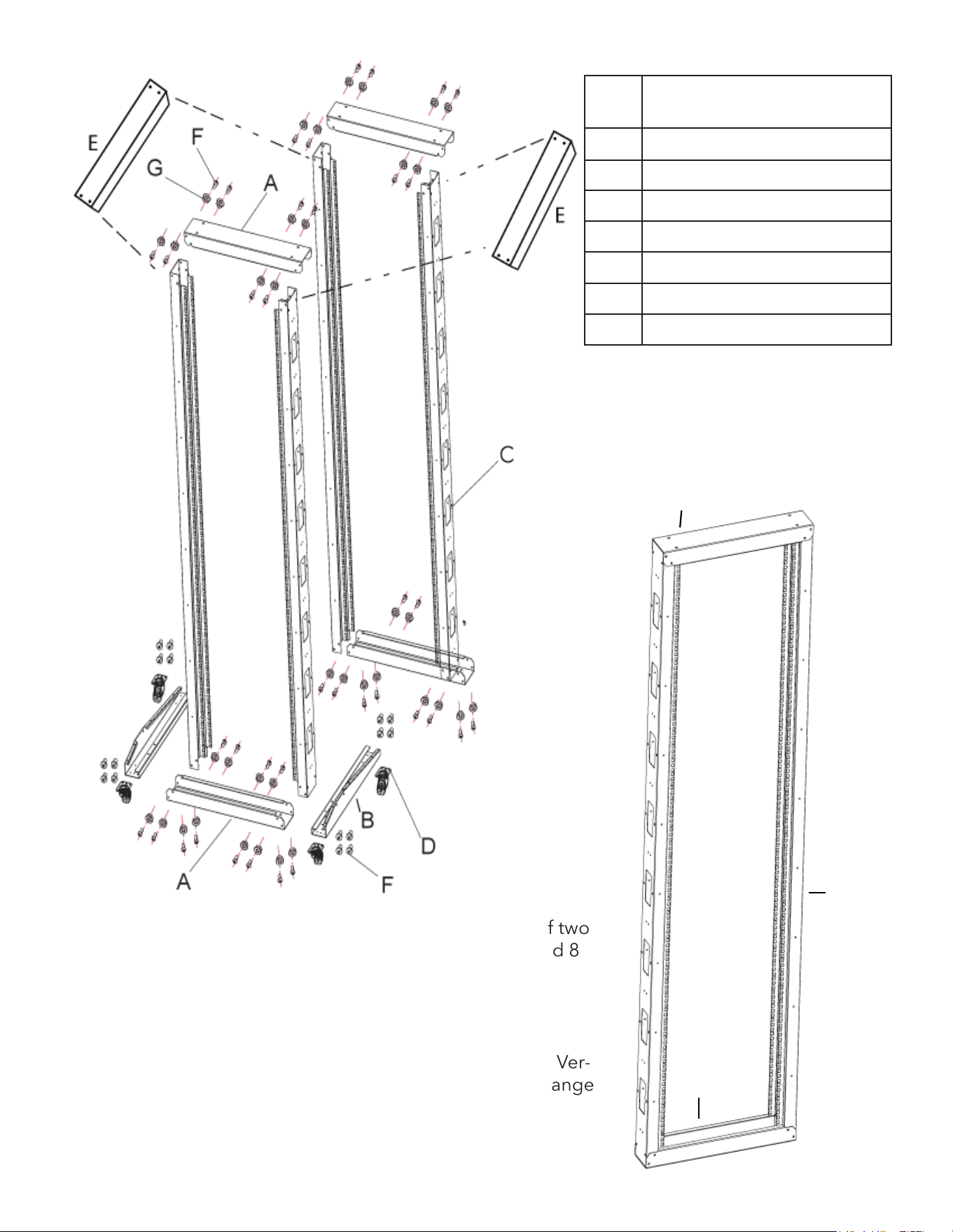
Attach Horizontal Cross Bar (A) at the bottom of two
of the vertical Rails (C) using 8 M6 Screws (F) and 8
M6 Flange Nuts (G).
Attach Horizontal Cross Bar (A) at the top of the Ver-
tical Rails (C) using 8 M6 Screws (F) and 8 M6 Flange
Nuts (G).
Part Quantity
A Horizontal Cross bar x2
B Bottom Support Beam x2
C Vertical Rail x4
D Casters x4
E Top Support Beams x2
F M6 Screws x72
G M6 Flange Nuts x72
A
C
A
3
4
5
6
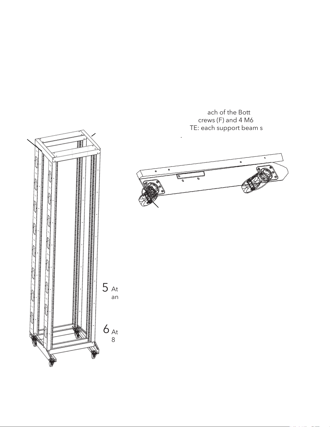
Repeat step 1 and step 2 to attach Horizontal Cross Bars(A)
to the other two Vertical Rails (C).
Attach two Casters (D) to each of the Bottom Support
Beams (B) using 4 M6 Screws (F) and 4 M6 Flange nuts (G)
for each Caster – NOTE: each support beam should have 1
Caster with Brake.
Attach Bottom Support Beams (B) to Frames using 8 M6 Screws (F)
and 8 M6 Flange Nuts (G).
Attach Top Support Beams (E) to Frames using 8 M6 Screws (F) and
8 M6 Flange Nuts (G).
D
B
E
E