For questions about features, operation/ performance, parts or service,
call: 1-877-465-3566
Operating hours (EST):
Monday - Friday from 9 a.m. to 9 p.m.
Saturday - Sunday from 9 a.m. to 6 p.m.
Language: English and Spanish
USE AND INSTALLATION MANUAL
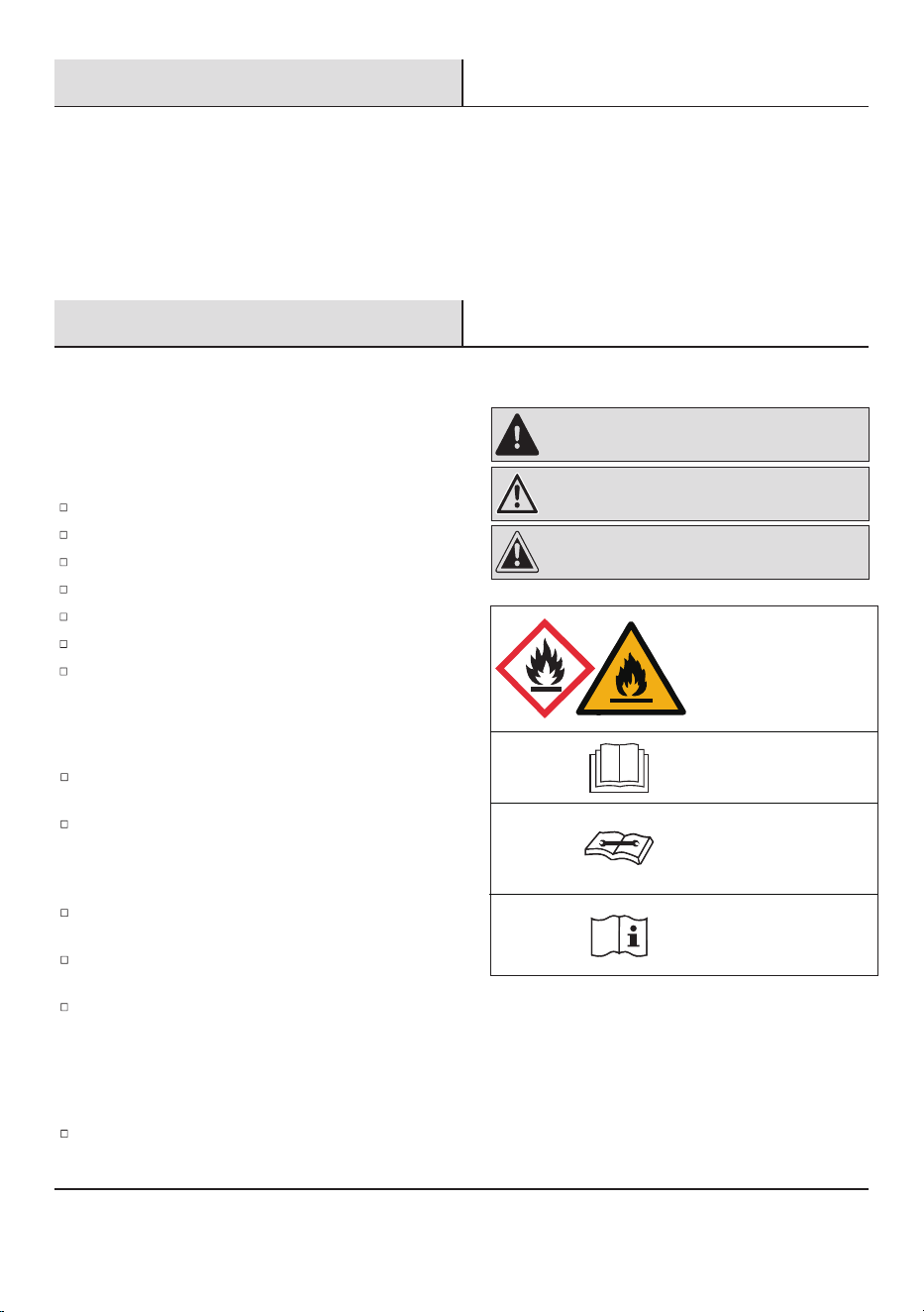
Table of Contents
Safety Information . . . . . . . . . . . . . . . . . . . . . . . . . . . . . . . . . . 2
Pre-Installation. . . . . . . . . . . . . . . . . . . . . . . . . . . . . . . . . . . . . 6
Planning Installation . . . . . . . . . . . . . . . . . . . . . . . . . . . . . . . 6
Tools Required . . . . . . . . . . . . . . . . . . . . . . . . . . . . . . . . . . . . 6
Hardware Included. . . . . . . . . . . . . . . . . . . . . . . . . . . . . . . . . 6
Package Contents . . . . . . . . . . . . . . . . . . . . . . . . . . . . . . . . . 7
Electrical Requirements. . . . . . . . . . . . . . . . . . . . . . . . . . . . . 8
Location Requirements . . . . . . . . . . . . . . . . . . . . . . . . . . . . .9
Unpack The Air Conditioner . . . . . . . . . . . . . . . . . . . . . . . . . 10
Window Vent Panel and Extensions . . . . . . . . . . . . . . . . . . . 10
Installation . . . . . . . . . . . . . . . . . . . . . . . . . . . . . . . . . . . . . . . 11
Operation. . . . . . . . . . . . . . . . . . . . . . . . . . . . . . . . . . . . . . . . . 14
Care and Cleaning . . .
. . . . . . . . . . . . . . . . . . . . . . . . . . . . . . 21
Troubleshooting . . . . . . . . . . . . . . . . . . . . . . . . . . . . . . . . . . . 24
2
Safety Information
All safety messages will tell you what the potential hazard is
and tell you how to reduce the chance of injury.
WARNING: A hazard that if not avoided could result In
death or serious Injury.
CAUTION: A hazard that if not avoided may result in
minor or moderate injury.
Explanation of symbols displayed on the unit.
Please recycle or dispose of the product packaging material in
an environmentally responsible manner.
Never store or ship the air conditioner upside down or sideways to
avoid damage to the compressor.
This appliance is not intended for use by persons (including children)
with reduced physical, sensory or mental capabilities,
or lack of experience and knowledge, unless they have been given
supervision or instruction concerning use of the appliance by a
person responsible for their safety. Children should be supervised to
ensure that they do not play with the appliance.
The wiring diagram is shown on nameplate on the air conditioner.
Plug into a grounded 3-prong outlet.
Do not remove ground prong.
Do not use an electrical adapter.
Do not use an extension cord.
Unplug air conditioner before servicing.
Use two or more people to move and install air conditioner.
If the SUPPLY CORD is damaged, it must be replaced by the
manufacturer, its service agent or similarly qualied persons in
order to avoid a hazard.
DISPOSING OF THE UNIT
Before throwing out the device, it is necessary to remove the battery
cells and dispose or recycle them properly.
When you need disposal of the unit consult our dealer. If pipes are
removed incorrectly, refrigerant may blow out and come into
contact with your skin, causing injury. Releasing refrigerant into
the atmosphere also damages the environments.
DANGER: A hazard that if not avoided will result In death
or serious injury.
A2L
WARNING
This symbol shows that this
appliance uses a ammable
refrigerant.
If the refrigerant is leaked
and exposed to an external
ignition source, there is a
risk of re.
CAUTION
This symbol shows that the
operation manual should
be read carefully.
CAUTION
This symbol shows that a
service personnel should
be handling this equipment
with reference to the
installation manual.
CAUTION
This symbol shows that
information is available such
as the operating manual or
installation manual.
Your safety and the safety of others are very important.
We have
provided
many important safety messages in this manual and on
your
appliance. Please always
read and obey all safety messages.
To
reduce
the risk of fire, electrical shock or injury when using your air conditioner,
please follow these basic precautions:
IMPORTANT SAFETY INSTRUCTIONS
3
Safety Information (continued)
PRECAUTIONS FOR USING R32 REFRIGERANT
The basic installation work procedures are the same as the conventional refrigerant (R22 or R410A).
However, pay attention to the following:
1. Transport of equipment containing flammable refrigerants
Attention is drawn to the fact that additional transportation regulations may exist with respect to equipment containing ammable gas.
The maximum number of pieces of equipment or the conguration of the equipment permitted to be transported together will be
determined by the applicable transport regulations.
2. Marking of equipment using signs
Signs for similar appliances used in a work area are generally addressed by local regulations and give the minimum requirements for
the provision of safety and/or health signs for a work location.
All required signs are to be maintained and employers should ensure that employees receive suitable and sufcient instruction and
training on the meaning of appropriate safety signs and the actions that need to be taken in connection with these signs.The
effectiveness of signs should not be diminished by too many signs being placed together. Any pictograms used should be as simple as
possible and contain only essential details.
3. Disposal of equipment using flammable refrigerants
See national regulations.
4. Storage of equipment/appliances
The storage of the appliance should be in accordance with the applicable regulations or instructions, whichever is more stringent.
5. Storage of packed (unsold) equipment
Storage package protection should be constructed in such a way that mechanical damage to the equipment inside the package will not
cause a leak of the refrigerant charge.
The maximum number of pieces of equipment permitted to be stored together will be determined by local regulations.
6. Information on servicing
Where electrical components are being changed, they shall be t for the purpose and to the correct specication. At all times the
manufacturer’s maintenance and service guidelines shall be followed. If in doubt, consult the manufacturer’s technical department
for assistance.
The following checks shall be applied to installations using FLAMMABLE REFRIGERANTS:
· the actual REFRIGERANT CHARGE is in accordance with the room size within which the refrigerant containing parts are installed;
· the ventilation machinery and outlets are operating adequately and are not obstructed;
· if an indirect refrigerating circuit is being used, the secondary circuit shall be checked for the presence of refrigerant;
· marking to the equipment continues to be visible and legible. Markings and signs that are illegible shall be corrected;
· refrigerating pipe or components are installed in a position where they are unlikely to be exposed to any substance which may
corrode refrigerant containing components, unless the components are constructed of materials which are inherently resistant to
being corroded or are suitably protected against being so corroded.
Maintenance, service, and repair personnel must be trained according to UL/CSA 60335-2-40 Ed 4.0 Annex HH and possess the
required qualifications.
For Models employing Flammable Refrigerant, the user instruction shall also contain the following information:
1. Prior to beginning work on systems containing FLAMMABLE REFRIGERANTS, safety checks are necessary to ensure that the risk
of ignition is minimised.
2. For repair to the REFRIGERATING SYSTEM, the following shall be completed prior to conducting work on the system.
· Work shall be undertaken under a controlled procedure so as to minimise the risk of a ammable gas or vapour being present
while the work is being performed.
· All maintenance staff and others working in the local area shall be instructed on the nature of work being carried out. Work in
conned spaces shall be avoided.
· The area shall be checked with an appropriate refrigerant detector prior to and during work, to ensure the technician is aware of
potentially toxic or ammable atmospheres. Ensure that the leak detection equipment being used is suitable for use with all
applicable refrigerants, i.e. non-sparking, adequately sealed or intrinsically safe.
· If any hot work is to be conducted on the refrigerating equipment or any associated parts, appropriate re extinguishing equipment
shall be available to hand. Have a dry powder or CO2 re extinguisher adjacent to the charging area.
· No person carrying out work in relation to a REFRIGERATING SYSTEM which involves exposing any pipe work shall use any sources
of ignition in such a manner that it may lead to the risk of re or explosion. All possible ignition sources, including cigarette
smoking, should be kept sufciently far away from the site of installation, repairing, removing and disposal, during which refrigerant
can possibly be released to the surrounding space. Prior to work taking place, the area around the equipment is to be surveyed to
make sure that there are no ammable hazards or ignition risks. “No Smoking” signs shall be displayed.
Repair and maintenance to electrical components shall include initial safety checks and component inspection procedures.
If a fault exists that could compromise safety, then no electrical supply shall be connected to the circuit until it is satisfactorily dealt
with. If the fault cannot be corrected immediately but it is necessary to continue operation, an adequate temporary solution shall be
used. This shall be reported to the owner of the equipment so all parties are advised.

Safety Information (continued)
4
NOTE: Examples of leak detection uids are
- bubble method,
- uorescent method agents.
Initial safety checks shall include:
· that capacitors are discharged: this shall be done in a safe manner to avoid possibility of sparking;
· that no live electrical components and wiring are exposed while charging, recovering or purging the system;
· that there is continuity of earth bonding.
7. Sealed electrical components shall be replaced. 8. Intrinsically safe components must be replaced.
9. Cabling
Check that cabling will not be subject to wear, corrosion, excessive pressure, vibration, sharp edges or any other adverse
environmental effects. The check shall also take into account the effects of aging or continual vibration from sources such as
compressors or fans.
10. Detection of flammable refrigerants
Under no circumstances shall potential sources of ignition be used in the searching for or detection of refrigerant leaks. A halide torch
(or any other detector using a naked ame) shall not be used.
11. Leak detection methods
The following leak detection methods are deemed acceptable for all refrigerant systems.
Electronic leak detectors may be used to detect refrigerant leaks but, in the case of FLAMMABLE REFRIGERANTS, the sensitivity
may not be adequate, or may need re-calibration. (Detection equipment shall be calibrated in a refrigerant-free area.) Ensure that
the detector is not a potential source of ignition and is suitable for the refrigerant used. Leak detection equipment shall be set at a
percentage of the LFL of the refrigerant and shall be calibrated to the refrigerant employed, and the appropriate percentage of gas
(25 % maximum) is conrmed.
Leak detection uids are also suitable for use with most refrigerants but the use of detergents containing chlorine shall be avoided
as the chlorine may react with the refrigerant and corrode the copper pipe-work.
If a leak is suspected, all naked ames shall be removed/extinguished.
If a leakage of refrigerant is found which requires brazing, all of the refrigerant shall be recovered from the system, or isolated (by
means of shut off valves) in a part of the system remote from the leak.
12. Removal and evacuation
When breaking into the refrigerant circuit to make repairs - or for any other purpose - conventional procedures shall be used.
However,for ammable refrigerants it is important that best practice be followed, since ammability is a consideration.
The following procedure shall be adhered to:
- safely remove refrigerant following local and national regulations;
- evacuate
- purge the circuit with inert gas (optional for A2L);
- evacuate ( optional for A2L);
- continuously ush or purge with inert gas when using ame to open circuit;
- open the circuit.
The refrigerant charge shall be recovered into the correct recovery cylinders if venting is not allowed by local and national codes.
For appliances containing ammable refrigerants, the system shall be purged with oxygen - free nitrogen to render the appliance
safe for ammable refrigerants. This process might need to be repeated several times. Compressed air or oxygen shall not be used
for purging refrigerant systems.
For appliances containing ammable refrigerants , refrigerants purging shall be achieved by breaking the vacuum in the system
with oxygen - free nitrogen and continuing to ll until the working pressure is achieved, then venting to atmosphere, and nally
pulling down to a vacuum ( optional for A2L). This process shall be repeated until no refrigerant is within the system ( optional for
A2L). When the nal oxygen - free nitrogen charge is used, the system shall be vented down to atmospheric pressure to enable
work to take place.
The outlet for the vacumm pump shall not be close to any potential ignition sources, and ventilation shall be available.
13. Charging procedures
In addition to conventional charging procedures, the following requirements shall be followed.
· Ensure that contamination of different refrigerants does not occur when using charging equipment.
· Hoses or lines shall be as short as possible to minimise the amount of refrigerant contained in them.
· Cylinders shall be kept in an appropriate position according to the instructions.
· Ensure that the REFRIGERATING SYSTEM is earthed prior to charging the system with refrigerant.
· Label the system when charging is complete (if not already).
· Extreme care shall be taken not to overll the REFRIGERATING SYSTEM.
Prior to recharging the system, it shall be pressure-tested with the appropriate purging gas. The system shall be leak-tested on
completion of charging but prior to commissioning. A follow up leak test shall be carried out prior to leaving the site.
Safety Information (continued)
5
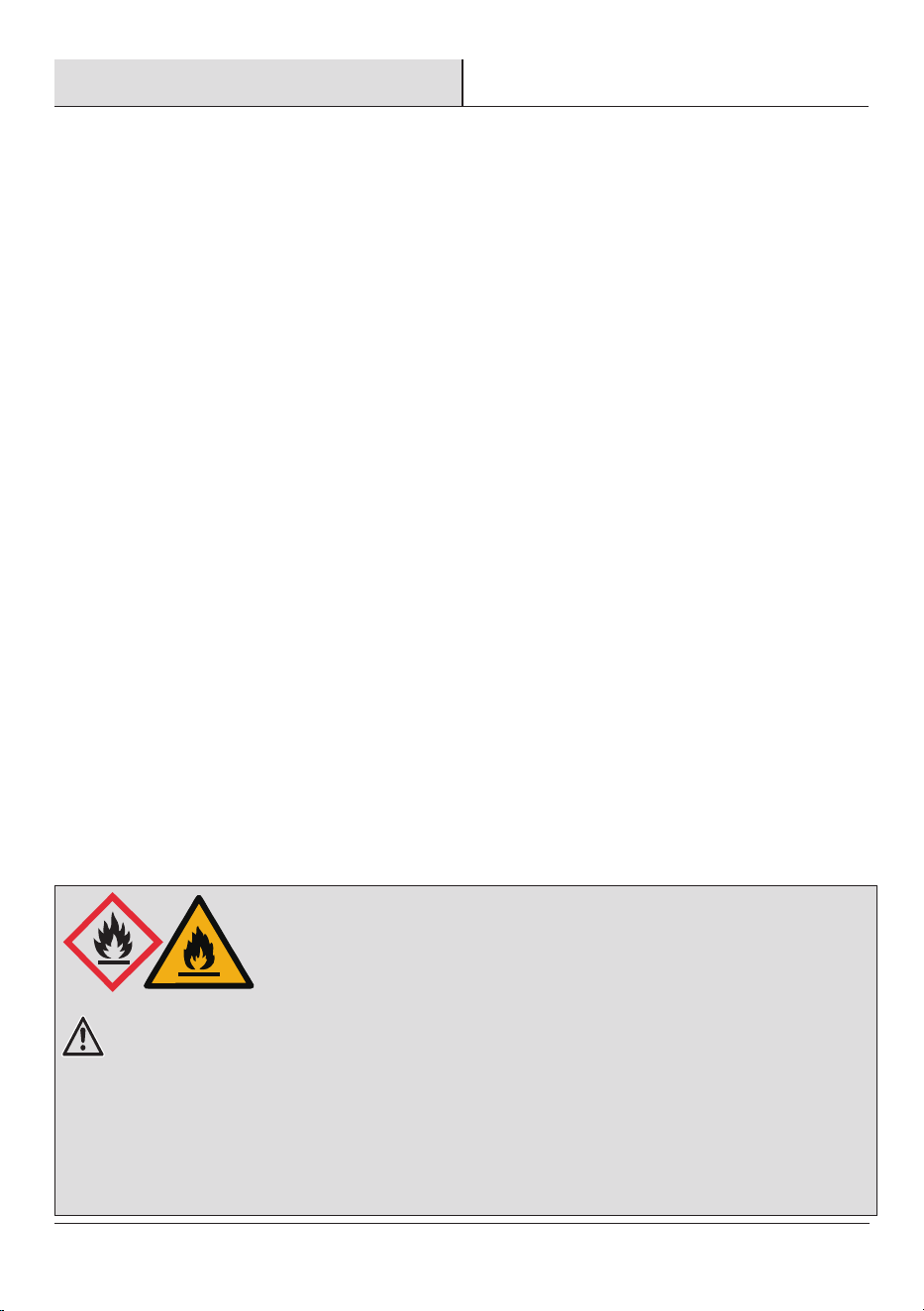
A2L
WARNING:
Risk of Fire or Explosion.
This unit contains ammable refrigerant.
Additional safety precautions must be followed.
14. Decommissioning
Before carrying out this procedure, it is essential that the technician is completely familiar with the equipment and all its detail. It is
recommended good practice that all refrigerants are recovered safely. Prior to the task being carried out, an oil and refrigerant
sample shall be taken in case analysis is required prior to re-use of recovered refrigerant. It is essential that electrical power is
available before the task is commenced.
a) Become familiar with the equipment and its operation.
b) Isolate system electrically.
c) Before attempting the procedure, ensure that:
· mechanical handling equipment is available, if required, for handling refrigerant cylinders;
· all personal protective equipment is available and being used correctly;
· the recovery process is supervised at all times by a competent person;
· recovery equipment and cylinders conform to the appropriate standards.
d) Pump down refrigerant system, if possible.
e) If a vacuum is not possible, make a manifold so that refrigerant can be removed from various parts of the system.
f) Make sure that cylinder is situated on the scales before recovery takes place.
g) Start the recovery machine and operate in accordance with instructions.
h) Do not overll cylinders (no more than 80 % volume liquid charge).
i) Do not exceed the maximum working pressure of the cylinder, even temporarily.
j) When the cylinders have been lled correctly and the process completed, make sure that the cylinders and the equipment are
removed from site promptly and all isolation valves on the equipment are closed off.
k) Recovered refrigerant shall not be charged into another REFRIGERATING SYSTEM unless it has been cleaned and checked.
15. Labelling
Equipment shall be labelled stating that it has been de-commissioned and emptied of refrigerant. The label shall be dated and
signed. For appliances containing FLAMMABLE REFRIGERANTS, ensure that there are labels on the equipment stating the equipment
contains FLAMMABLE REFRIGERANT.
16. Recovery
When removing refrigerant from a system, either for servicing or decommissioning, it is recommended good practice that all
refrigerants are removed safely.
When transferring refrigerant into cylinders, ensure that only appropriate refrigerant recovery cylinders are employed.
Ensure that the correct number of cylinders for holding the total system charge is available. All cylinders to be used are designated for the
recovered refrigerant and labelled for that refrigerant (i.e. special cylinders for the recovery of refrigerant). Cylinders shall be complete
with pressure-relief valve and associated shut-off valves in good working order. Empty recovery cylinders are evacuated and, if possible,
cooled before recovery occurs.
The recovery equipment shall be in good working order with a set of instructions concerning the equipment that is at hand and shall be
suitable for the recovery of the ammable refrigerant. If in doubt, the manufacturer should be consulted. In addition, a set of calibrated
weighing scales shall be available and in good working order.
Hoses shall be complete with leak-free disconnect couplings and in good condition.
The recovered refrigerant shall be processed according to local legislation in the correct recovery cylinder, and the relevant waste
transfer note arranged. Do not mix refrigerants in recovery units and especially not in cylinders.
If compressors or compressor oils are to be removed, ensure that they have been evacuated to an acceptable level to make certain
that ammable refrigerant does not remain within the lubricant. The compressor body shall not be heated by an open ame or other
ignition sources to accelerate this process. When oil is drained from a system, it shall be carried out safely.
1. Do not use means to accelerate the defrosting process or to clean, other than those recommended by the manufacturer.
2.
The appliance shall be stored in a room without continuously operating ignition sources
(for example: open ames, an operating gas appliance or an operating electric heater).
3. Do not pierce or burn refrigerant tubing. Be aware that refrigerants may not contain an odor.
4. Compliance with national gas regulations shall be observed.
5. Keep ventilation openings clear of obstruction.The maximum refrigerant charge amount is shown on the nameplate on the air conditioner.
6. When handling, installing, and operating the appliance, care should be taken to avoid damage to the refrigerant tubing.
7. Do not drill holes in the unit.
8. Dispose of air conditioner in accordance with Federal and Local Regulations. Flammable refrigerants require special disposal
procedures.
9. Contact your local authorities for the environmentally safe disposal of your air conditioner.
10. The appliance shall be stored so as to prevent mechanical damage from occurring.
11. The appliance shall be stored in a well-ventilated area where the room size corresponds to the room area as specied for operation.
12. This product contains small parts such as (batteries, battery cover and screws) that may cause suffocation if swallowed by
children.
Pre-Installation
PLANNING INSTALLATION
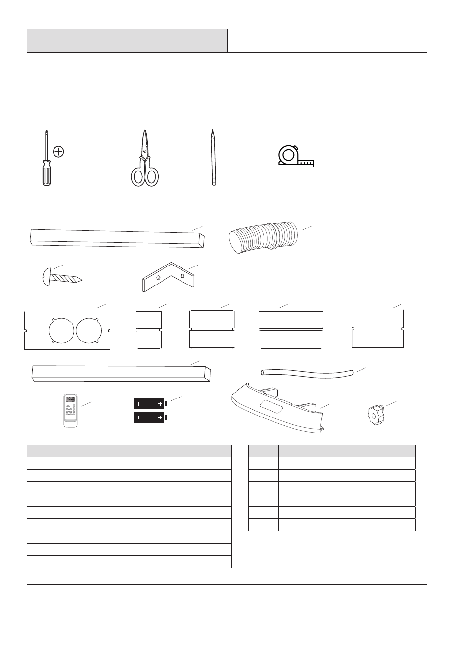
Gather the required tools and parts before starting installation. Check that all parts are included in parts package. Read and follow the
instructions provided with any tools listed here.
TOOLS REQUIRED
Phillips
screwdriver
Scissors Pencil
HARDWARE INCLUDED
LL
KK
NN
OO
MM
Part Description
AA Foam seal (non-adhesive)
BB
CC
DD
EE
FF
Screws
GG
Window lock bracket
Vent panel 19 3/10"
Extension panel 5 7/10"
Extension panel 10"
Extension panel 14 3/10"
Extension panel 11 3/5"
HH
II
6
Quantity
1
1
1
1
1
1
4
2
2
AA
BB
CC DD
FF
GG
HH II
JJ
EE
Part Description
JJ
KK
LL
Foam seal-long (adhesive)
MM
NN
Drain hose (Heat pump models)
Standard AAA (1.5 volt) batteries
Mounting plate
Quantity
3
1
1
2
4
OO Locking kit
4
Remote control
Flexible hose (installed on the model)
FILTER
SUPER
MODE FAN
QUIET
TIMER DIMMER
Sleep [ 5 sec ]
SWING
F / C [ 5 sec ]
Tape measure
Pre-Installation (continued)
NOTE:
Mercury free super heavy duty R03 UM-4 size AAA 1.5V.
Best used before date code (month-year) on the bottom.
Caution for ingestion: the battery may cause suffocation if swallowed by children.
Do not mix old and new batteries. Do not mix alkaline, standard (carbon - zinc), or rechargeable (nickel - cadmium)
batteries. Non-rechargeable batteries are not to be recharged.
Exhausted batteries are to be removed from the product.
DO NOT DISPOSE OF BATTERIES IN FIRE. BATTERIES MAY EXPLODE OR LEAK.
PACKAGE CONTENTS
7
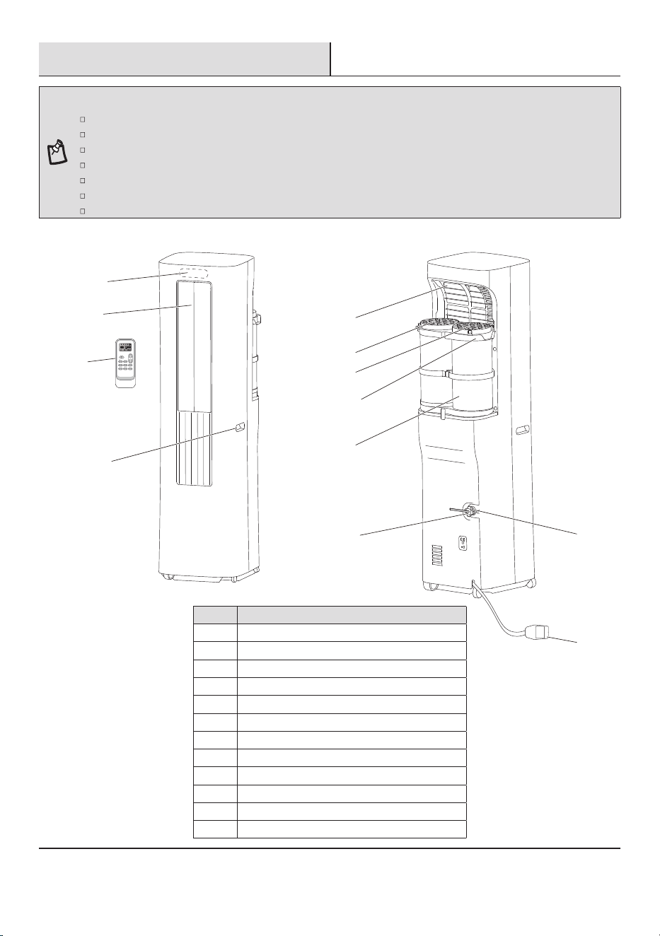
Part Description
A Control panel
B
C
D
Remote control
E
Transport handle
F
Evaporator air intake
G
H
Condenser air intake
Window adapter
Condenser air outtake
I
J Drain cover
Cool air outlet
K Drain port
L Power cord (may differ from the one shown)
Flexible hose
C
D
A
B
FILTER
SUPER
MODE FAN
QUIET
TIMER DIMMER
Sleep [ 5 sec ]
SWING
F / C [ 5 sec ]
E
F
G
H
I
L
J
K
Pre-Installation (continued)
8
ELECTRICAL REQUIREMENTS
Recommended Grounding Method
This portable air conditioner must be grounded. This portable air conditioner is equipped with a power supply cord with a three-prong
grounding plug. The cord must be plugged into a properly grounded three-prong outlet, grounded in accordance with all local codes and
ordinances. If a properly grounded outlet is not available, it is the customer’s responsibility to have a properly grounded three-prong outlet
Customer’s Responsibility
To assure that the electrical installation is adequate and conforms to the national electrical code, ANSI/NFPA 70-last edition, and all
local codes and ordinances.
Copies of the standards listed may be obtained from:
National Fire Protection Association
1 Batterymarch Park
Quincy, MA 02169-7471
www.nfpa.org
Wiring Requirement
Power Supply Cord
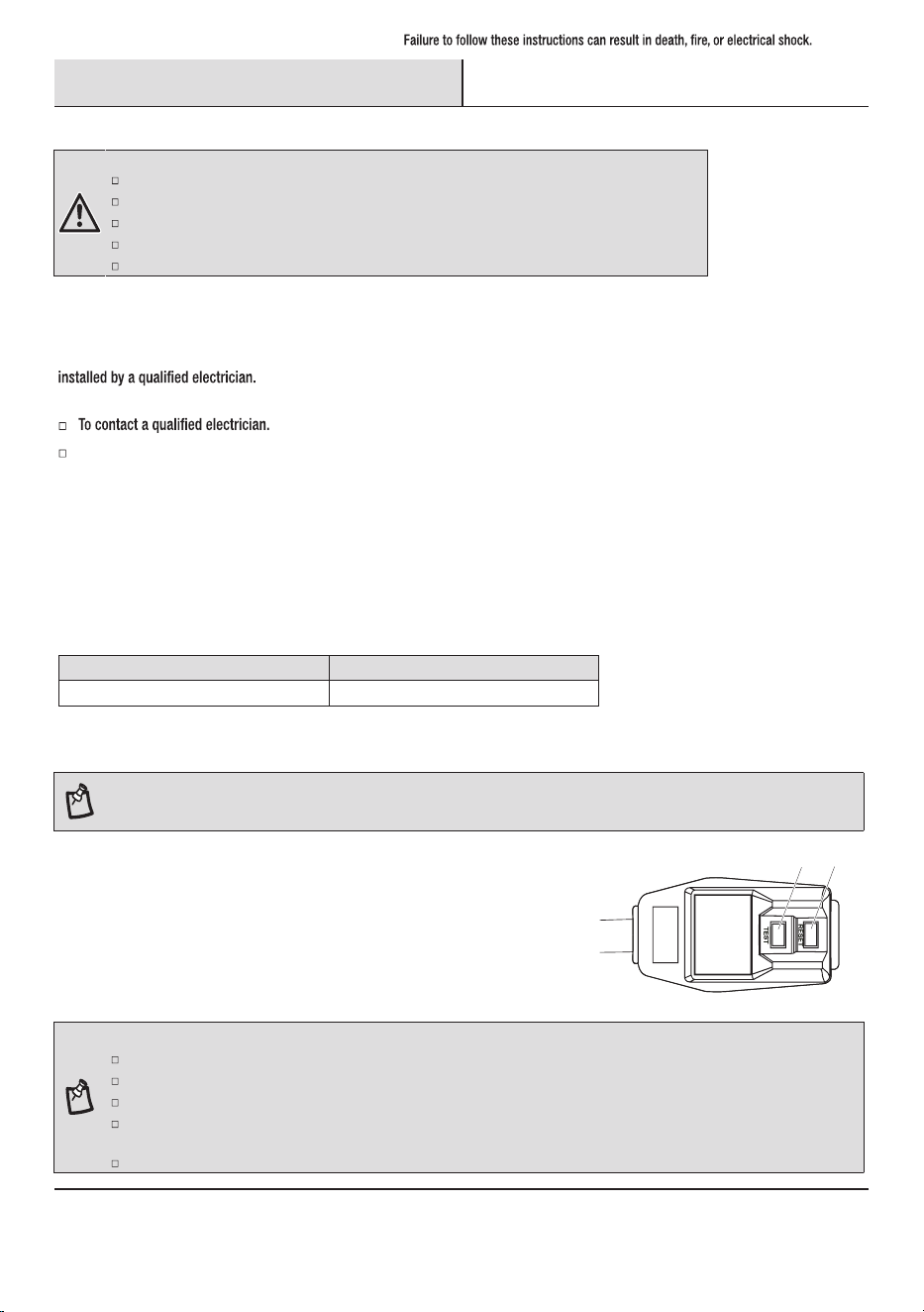
NOTE: Your air conditioner’s device may differ from the one shown. This room air conditioner is equipped with a power supply cord required
by UL. This power supply cord contains state-of-the-art electronics that sense leakage current. If the cord is crushed, the electronics detect
leakage current and power will be disconnected in a fraction of a second.
To test your power supply cord:
1. Plug power supply cord into a grounded 3-prong outlet.
2. Press RESET (2) (on some devices, a green light will turn on).
3. Press TEST (1) and listen for click. The RESET button will trip, and on some devices, a
green light will turn off.
4. Press and release RESET (2) and listen for click. The RESET button will latch, and on
some devices, a green light will turn on. The power supply cord is ready for operation.
1
2
Time-delay fuse (or circuit breaker)Power supply
15A115V 103.5V min. 126.5V max.
NOTE:
The RESET button must be pushed in for proper operation.
The power supply cord must be replaced if it fails to trip when the test button is pressed or fails to reset.
Do not use the power supply cord as an off/on switch. The power supply cord is designed as a protective device.
If the SUPPLY CORD is damaged, it must be replaced by the manufacturer, its service agent or similarly qualified persons in order to
avoid a hazard.
The power supply cord contains no user serviceable parts. Opening the tamper-resistant case voids all warranty and performance claims.
WARNING:
Plug into a grounded 3-prong outlet.
Do not remove ground prong.
Do not use an adapter.
Do not use an extension cord. The appliance shall be installed in accordance with national wiring regulations.
Failure to follow these instructions can result in fire, electrical shock, or death.
Pre-Installation (continued)
LOCATION REQUIREMENTS
Area to be cooled DOE Capacity needed (BTUs)
Up to 10 ft x 15 ft room 150 sq. ft
Up to 10 ft x 25 ft room 250 sq.ft
Up to 15 ft x 20 ft room 300 sq. ft
Up to 10 ft x 35 ft room 350 sq. ft
NOTE: Match BTUs to room use and location: Shaded room, reduce to next smaller size;
sunny room, increase to next larger size; for kitchens, increase to next larger size.
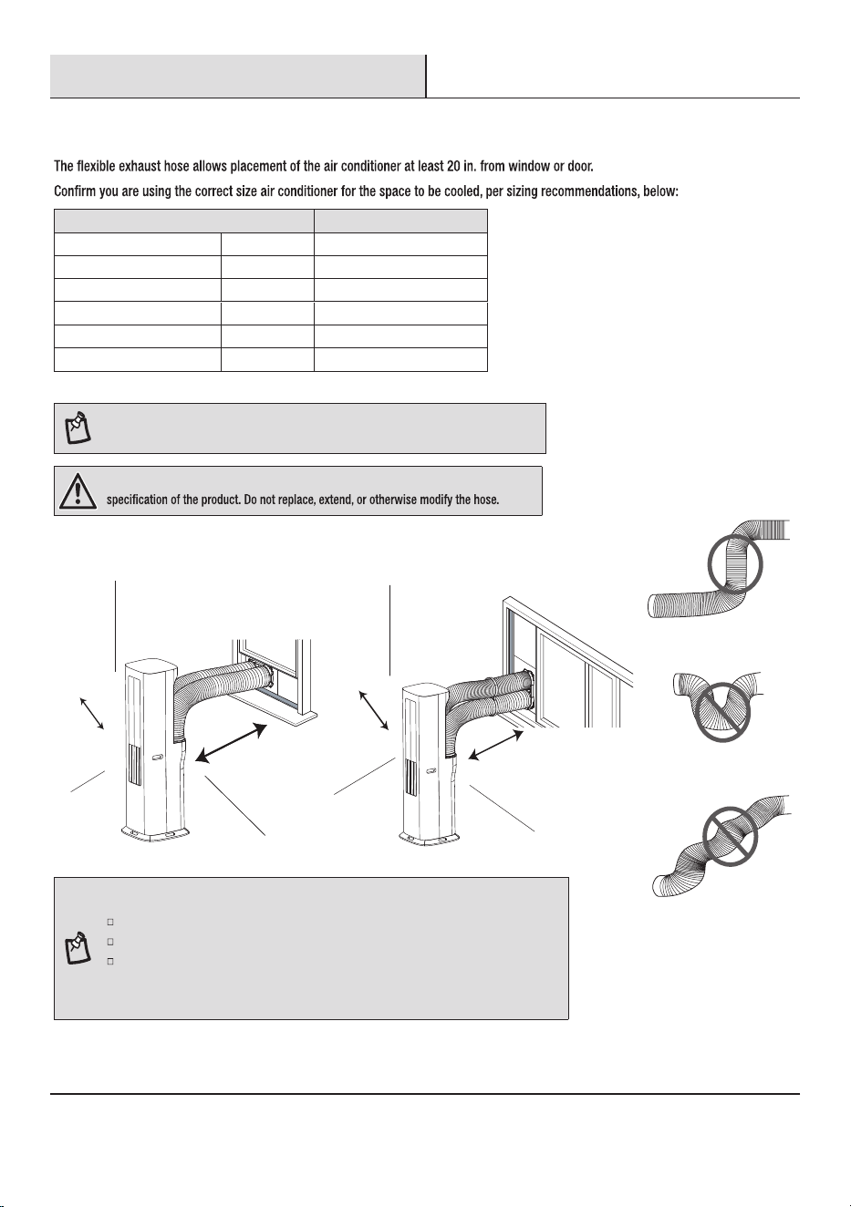
WARNING: The length of the exhaust hose is specially designed according to the
9
NOTE: For best performance, allow at least 20 in. of air space on all sides of the unit for good
air circulation.
Do not block the air outlet.
Provide easy access to the grounded 3-prong outlet.
To ensure proper function, DO NOT overextend or bend the hose. Make sure that there is
no obstacle around the air outlet of the exhaust hose in order for the exhaust system to
work properly. All the illustrations in this manual are for explanation purposes only. Your air
conditioner may be slightly different. The actual shape shall prevail.
450 sq. ft.Up to 15 ft x 30 ft room
5,000
6,000
7,000
8,000
10,000
550 sq. ft.Up to 10 ft x 55 ft room 12,000
Horizontal Sliding Window
20 in.
(50 cm)
20 in.
(50 cm)
20 in.
(50 cm)
Vertical Sliding Window
20 in.
(50 cm)
20 in.
(50 cm)
Pre-Installation (continued)
10
UNPACK THE AIR CONDITIONER
WARNING: Use two or more people to move and install air conditioner. Failure to do so can result in
back or other injury.
Remove Packaging Materials
□ Remove and recycle packaging materials.
□ Remove tape and glue residue from surfaces before turning on the air conditioner. Rub a small amount of liquid dish soap over the
□
damage the surface of your air conditioner.
□ Handle the air conditioner gently.
IMPORTANT: Keep unit upright at least 2 hours prior to use.
CAUTION: Installation accessories are stored in the top of the carton and are required for proper
cooling performance. Please remove all accessories from packing materials before use.
WINDOW VENT PANEL AND EXTENSIONS
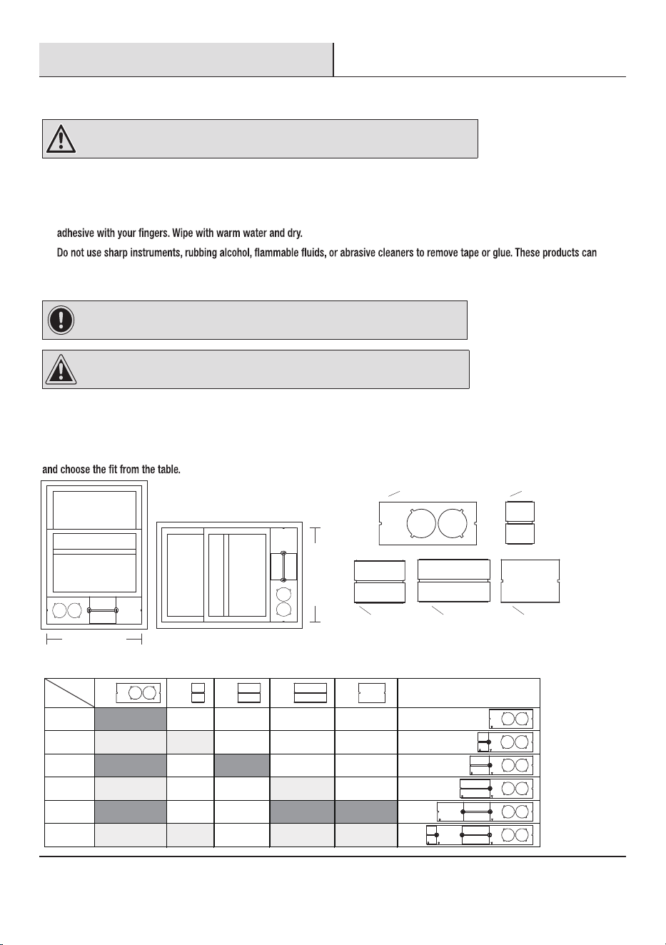
The window installation kit allows you to install the air conditioner in most vertical-sliding windows
19 in. to 50 in. wide, or horizontal sliding windows from 19 in. to 50 in. tall. Check your window size
Please choose accessories for installation based on the size of your window.
✔
✔ ✔
✔ ✔
✔ ✔
✔ ✔ ✔
19"
19"-23"
23"-27"
27"-31"
31"-42"
42"-50"
✔ ✔ ✔ ✔
IIGG
EE FF
HH
Assembly effect
Window
Panel
( 19 3/10" ) ( 5 7/10" )
( 14 3/10" )
FF
EE
GG
HH
( 11 3/5" )
II
( 10" )
19 in. to 50 in
19 in. to 50 in
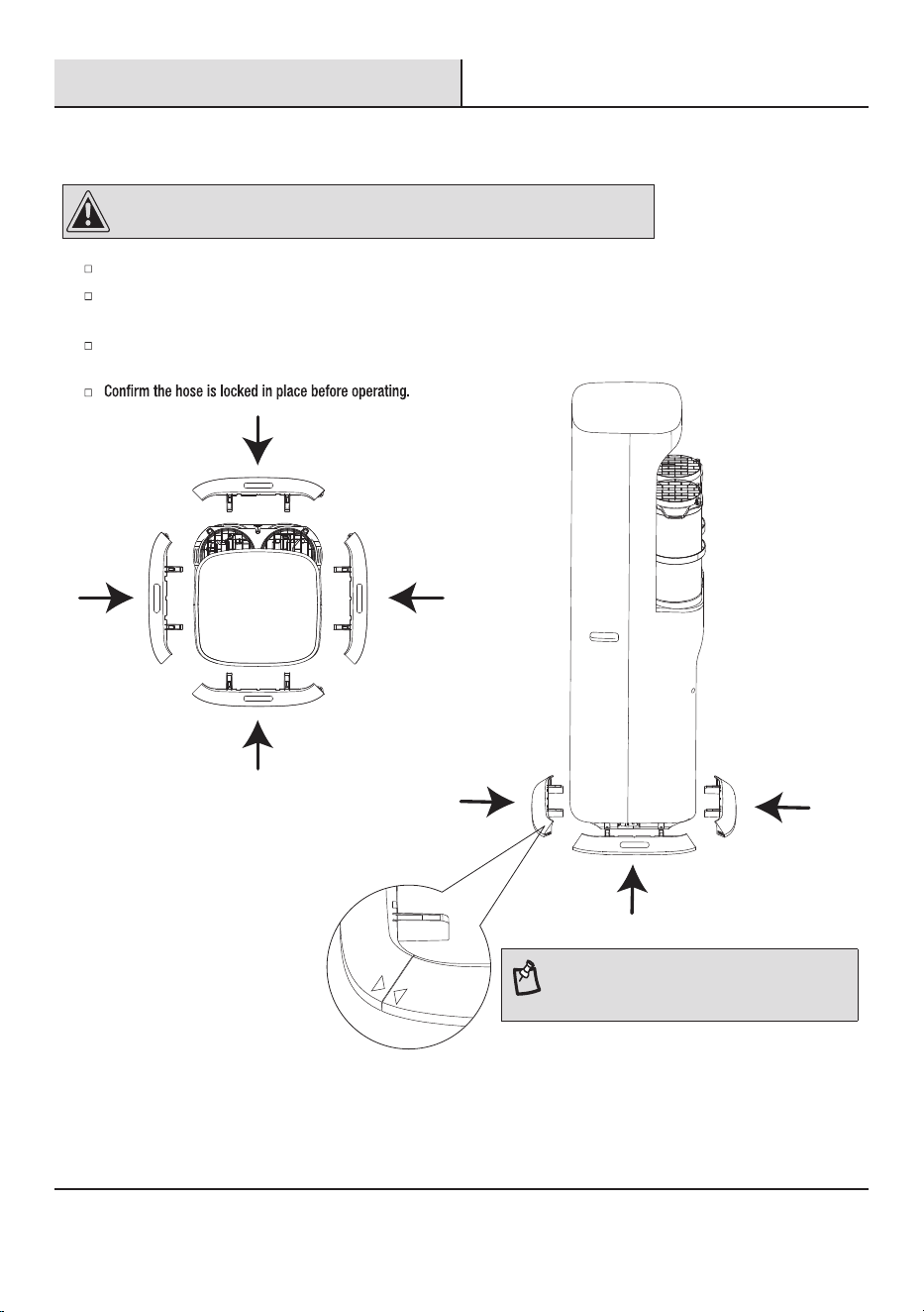
CAUTION: The Bottom Mounting plate must be installed before the machine can be used.
NOTE:
The triangular symbol on the mounting plate is deemed
to be properly installed as shown in the figure.
Installation
11
1
Attaching Mounting plate to Air Conditioner
Roll the air conditioner to selected location. See “Location Requirements” on page 9.
Air outlet hose coupling, flexible hose, condenser air intake and window adapter have been pre-installed by
factory, please check whether it is installed in place.
When attaching mounting plate to air conditioner, ensure all mounting plates are properly assembled and securely
positioned to support the unit.
Top view
Side view
A
B
AB
OO
AB
A
B
Installation (continued)
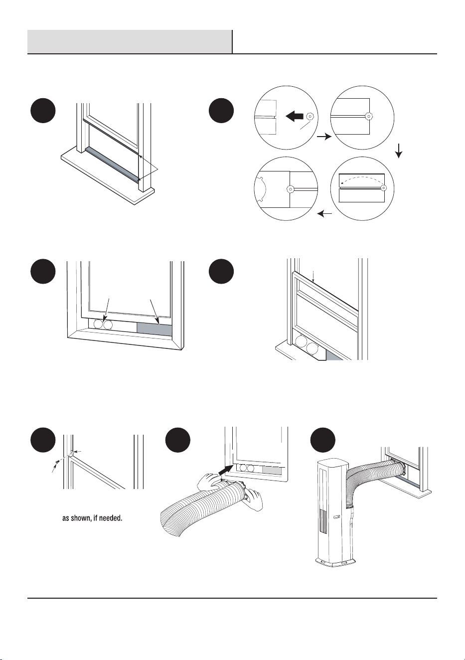
2a
1 2
3 4
5
6 7
Installing in Vertical Sliding Window
Cut the foam seal (AA) (non-adhesive type) to the
window width. Stuff the foam seal (AA) between the
glass and the window to prevent air and foreign
objects from getting into the room.
Connect the window adapter to the window.
Install the vent panel assembly (EE), including the
extended panels, into the window opening. Adjust the
extension panels to match the window width. Secure the
vent panel assembly (EE) by twisting the locking kit (OO).
12
The installation has been
successfully completed.
Cut the foam seal (JJ) (adhesive
type-long) to the proper length, and
attach it to the window sash and frame.
Insert the locking kit (OO) from point A to point B within the
extension panel. Add more extension panels as needed.
DD
CC
JJ
EE FF, GG, HH or II
AA
Install the window lock
bracket (DD) with screw (CC)
Installation (continued)
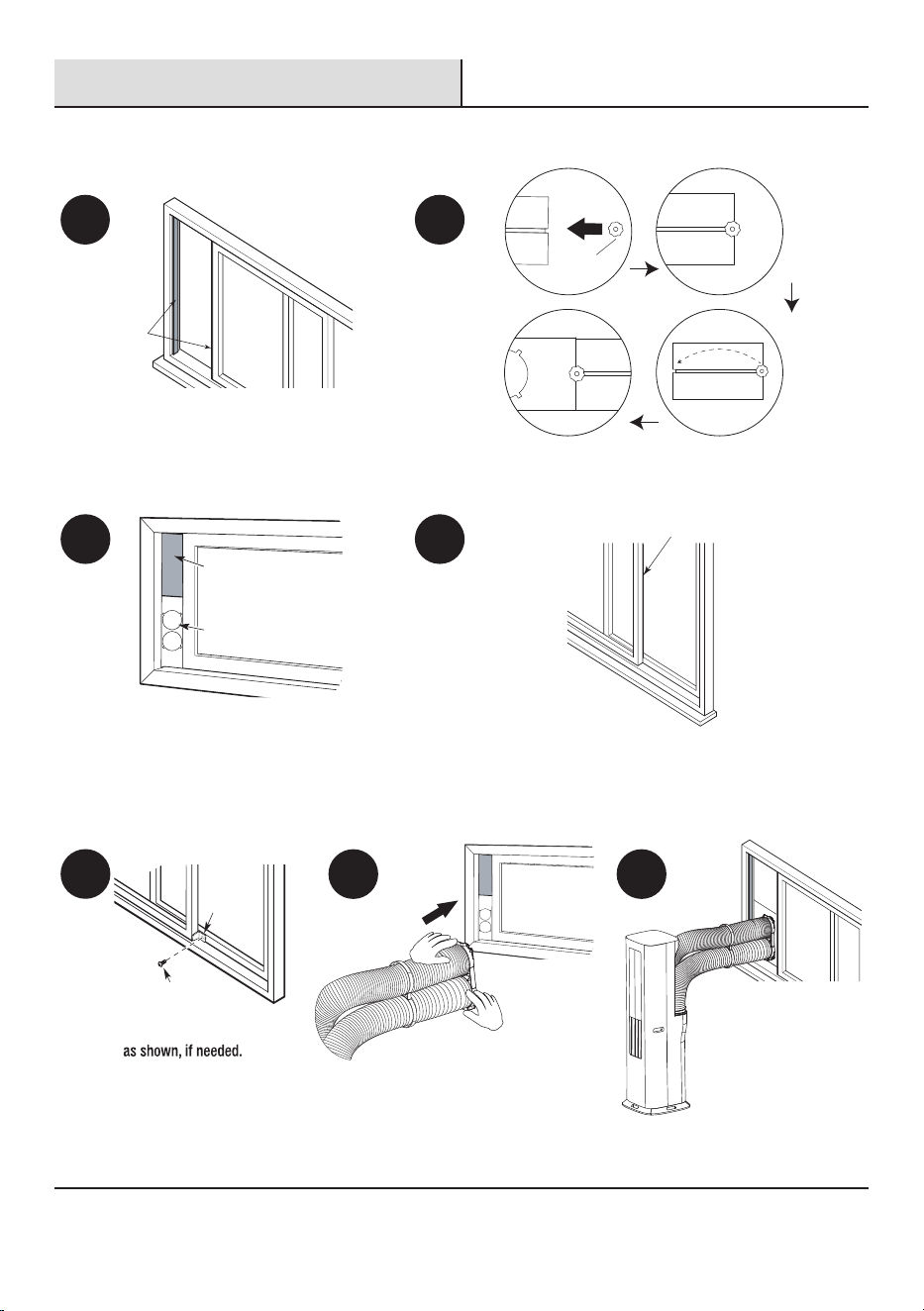
2b
1
2
3 4
5
6 7
Installing in Horizontal Sliding Window
Cut the foam seal (AA) (non-adhesive type) to the
window width. Stuff the foam seal (AA) between the
glass and the window to prevent air and foreign
objects from getting into the room.
Connect the hose to the window.
13
Cut the foam seal (JJ) (adhesive
type-long) to the proper length, and
attach it to the window sash and frame.
AA
CC
DD
JJ
EE
FF, GG, HH or II
A
B
AB
OO
AB
A
B
Install the window lock
bracket (DD) with screw (CC)
The installation has been
successfully completed.
Install the vent panel assembly (EE), including the
extended panels, into the window opening. Adjust the
extension panels to match the window width. Secure the
vent panel assembly (EE) by twisting the locking kit (OO).
Insert the locking kit (OO) from point A to point B within the
extension panel. Add more extension panels as needed.
14
NOTE: The evaporator may frost or freeze when DRY mode is used at low temperatures.
This is a normal occurrence and may impact the drying efficiency.
Operation
Operating your portable air conditioner properly helps you to obtain the best possible results. This section explains proper air conditioner operation.
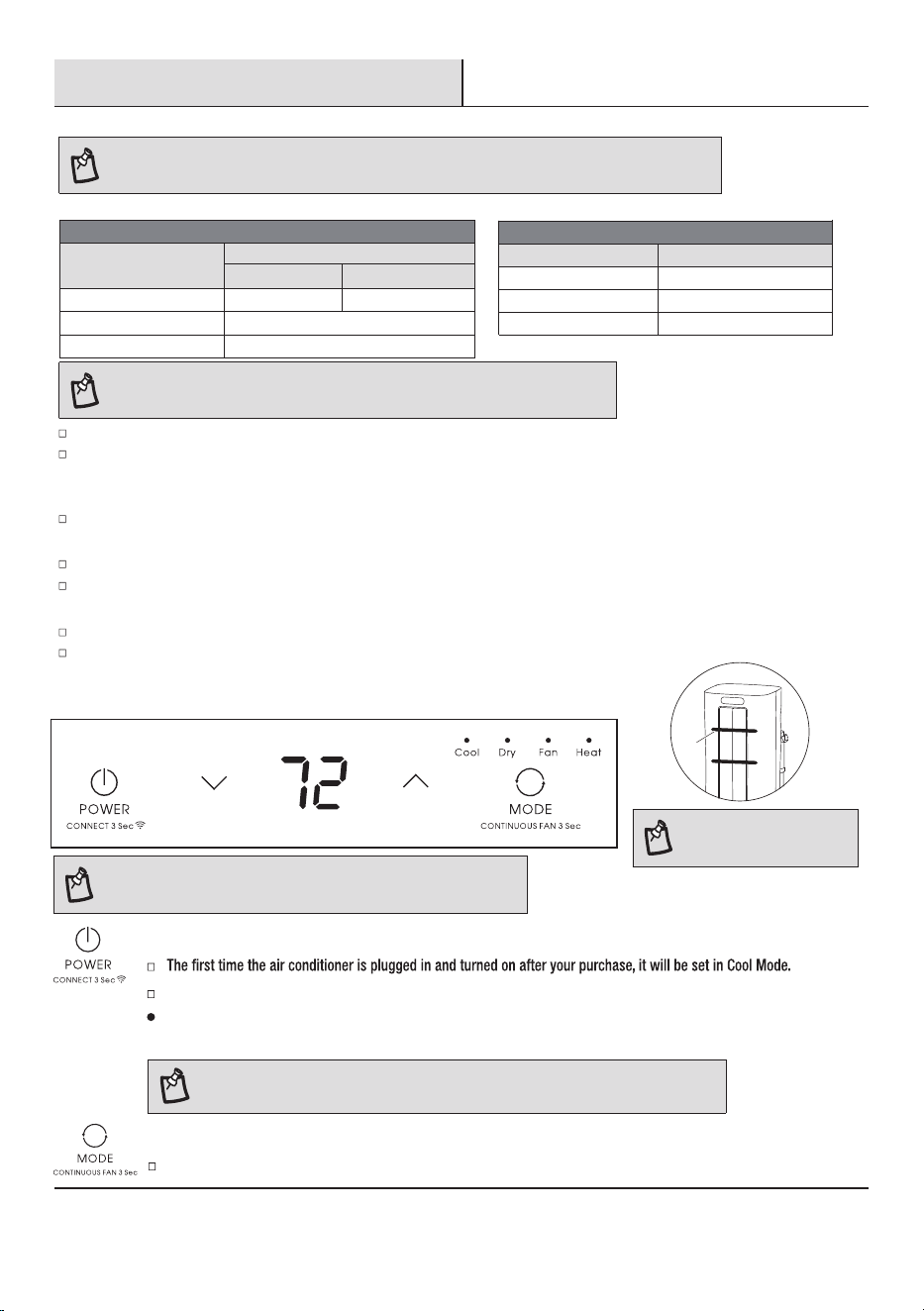
1
Using the Control Panel
NOTE:
Remove the tape before use.
POWER ON OR OFF
MODE
Press and release MODE until you see the symbol for the desired setting. Operating modes are Cool, Dry, Fan, or Heat.
NOTE: WIFI control is available for connected models with this logo on the control panel.
Tape
NOTE:
The symbols may be different from these models, but the functions are similar.
Do not stay in direct air flow from the air conditioner for extended periods of time.
Never use in tightly enclosed spaces. Always ensure there is sufficient air flow of outside air entering the household especially when
used in conjunction with combustible devices such as gas stoves, fireplaces, furnaces, hot water heaters etc. Do not place the power
cord or air conditioner near a heater, radiator, stoves or other apparatus (including amplifiers) that produce heat.
This air conditioner is intended for household use as a residential appliance. Do not use it as a precision climate control for commercial
use, or for precision equipment, food, pets, plants, artwork, etc.
Do not block or obstruct the exhaust vent hose as it may severely affect performance, or cause failure of the air conditioner.
When changing modes while the air conditioner is in operation, the compressor will stop for 3 to 5 minutes before restarting. If a button
is pressed during this time, the compressor will not restart for another 3 to 5 minutes.
In Cool
, Dry or Heat mode, the compressor and condenser fan will stop when the room temper
ature reaches the set temperature.
In Dry mode, the humidity level is automatically set, but is not able to be displayed.
Ambient Temperature Range For Unit Operating:
OutdoorIndoor
Cool
61-110°F (16-43°C)61-90°F (16-32°C)
Heat(heat pump model)
41-86°F (5-30°C)
Heat(electrical heat model)
Dual hose air conditioner
MODE
Ambient Temperature Range
MODE Ambient Temperature Range
61-95°F (16-35°C)Cool
Heat(heat pump model)
41-86°F (5-30°C)
Single hose air conditioner
Heat(electrical heat model)
NOTE:
In the event of a power failure,
your air conditioner will operate at the previous MODE, TEMPERATURE, and FAN
SPEED settings when the power is restored.
≤ 86°
F(30°C)
≤ 86°
F(30°C)
When the air conditioner is restarted after power off, it will run the previous MODE, TEMPERATURE, and FAN SPEED settings.
CONNECT:
Press and hold the POWER button for 3 seconds to enter WiFi pairing mode. For more details,
please refer to the instructions in the app.
Operation (continued)
NOTE:
In Cooling mode, the temperature can be set between 61 °F and 86 °F (16 °C and 30 °C).
In Fan Only mode, the temperature cannot be set.
CHANGE DISPLAY BETWEEN °F AND °C
To change the temperature display between °F and °C. Press both the and buttons at the same time.
15
2
Using the Remote Control
INSERT THE BATTERIES
Remove the battery cover along the arrowed direction.
Insert new batteries making sure that the (+) and (-) of battery are
matched correctly.
Reattach the cover by sliding it back into position.
NOTE:
Use 2 standard AAA (1.5 volt) batteries. Do not use rechargeable batteries.
Replace batteries with new ones of the same type when the display becomes dim, or after 6 months.
When replacing batteries, always replace both batteries with new batteries. Do not mix old and new batteries. Do not mix alkaline,
If the air conditioner will not be used for an extended period of time, remove the batteries from the remote.
DO NOT DISPOSE OF BATTERIES IN FIRE. BATTERIES MAY EXPLODE OR LEAK.
CAUTION: Do not use the remote if the batteries have leaked. The chemicals in batteries could cause burns or other health hazards.
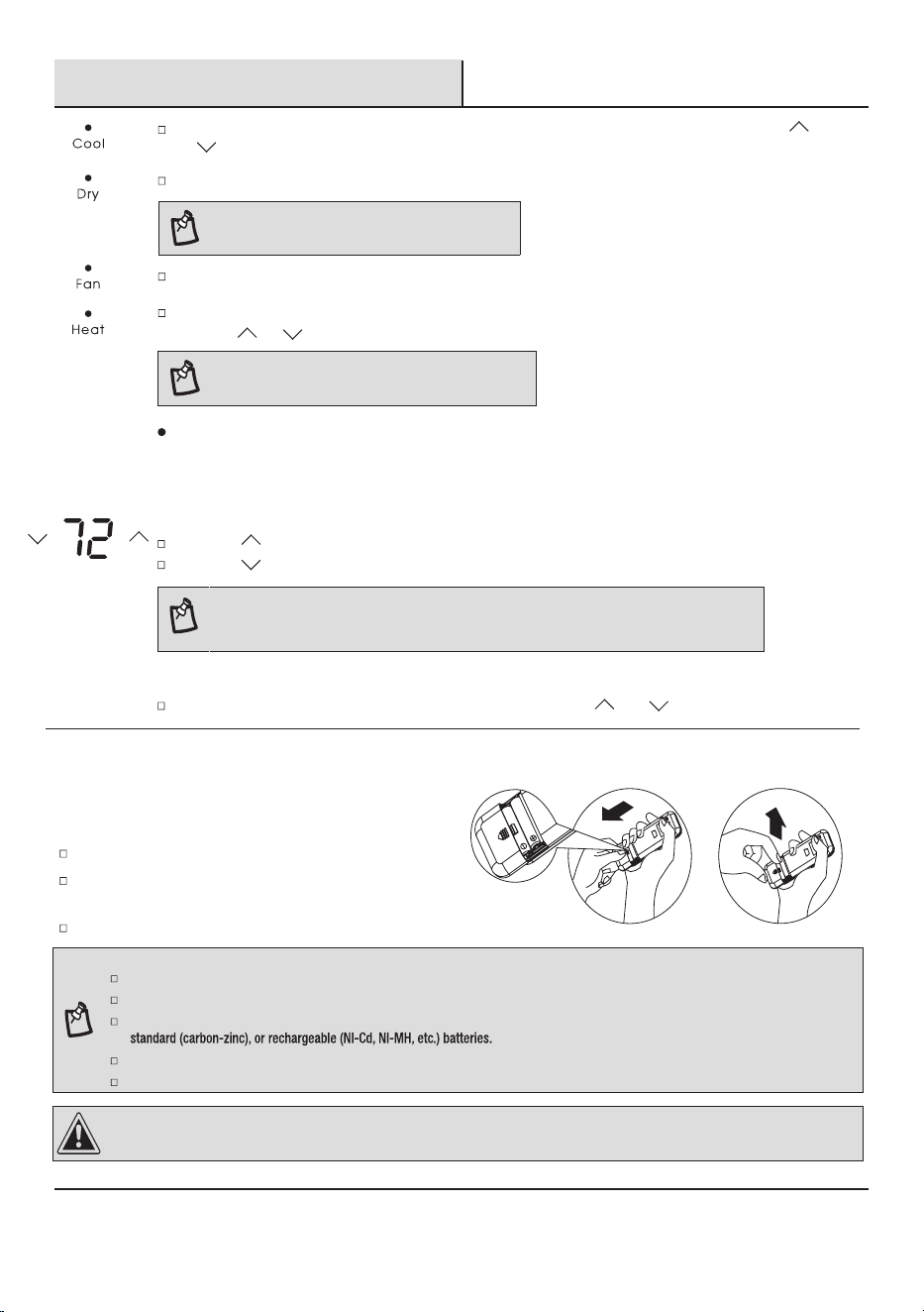
TEMPERATURE
Press the
button once to increase the set temperature by 1 °F (1 °C).
NOTE: This mode is available only for heat pump models.
Heat- Heats the room. Press FAN on the remote control the to select High, Mid or Low speeds.
Press the or button to adjust the temperature.
Press the button once to decrease the set temperature by 1 °F (1 °C).
Dry - Dries the room. The air conditioner automatically selects the temperature. The fan runs on Low speed only.
NOTE: Dry mode should not be used to cool the room.
Fan Only
mode. Press FAN on the remote control the to select High, Mid or Low speeds.
CONTINUOUS FAN: Press MODE and hold for 3 seconds to switch to continuous fan mode. In this mode,
the indoor fan will continue running even when the set temperature is reached. To return to the previous mode,
press and hold for 3 seconds again; the indoor fan will stop once the set temperature is reached.
Cool - Cools the room. Press FAN on the remote control the to select High, Mid or Low speeds. Press the
or button to adjust the temperature.
Operation (continued)
16
BUTTON FUNCTIONS
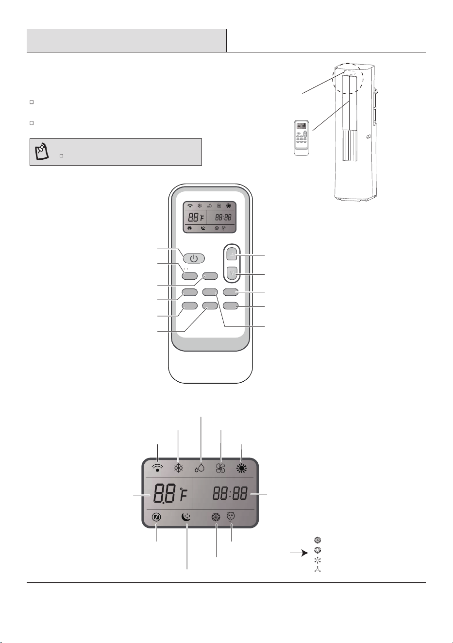
FILTERSUPERQUIET
MODE FAN
SWING TIMER DIMMER
Sleep [ 5 sec ]
F / C [ 5 sec ]
Mode
Fan
Quiet
Swing
Up
Down
Super
Filter
Dimmer/ Sleep
Timer
On/Off
INDICATION SYMBOLS
Timer
Heating indicator
Fan speed display
Quiet indicator
Cool indicator
Dry indicator
Fan only indicator
Display
set temperature
Sleep indicator
Super indicator
Signal transmission
Displays selected Fan speed:
Medium fan speed
Low fan speed
Auto fan speed
High fan speed
1
FILTER
SUPER
MODE FAN
QUIET
TIMER DIMMER
Sleep [ 5 sec ]
SWING
F / C
[ 5 sec ]
2
Using the Remote Control (continued)
HOW TO USE
To operate the room air conditioner, aim the remote control at the
signal receptor (1).
The remote control will operate the air conditioner at a distance of up
to 23 ft. (7 m) when pointing at signal receptor of the air conditioner.
NOTE:
Remote control may differ in appearance.
Operation (continued)
2
Using the Remote Control (continued)
17
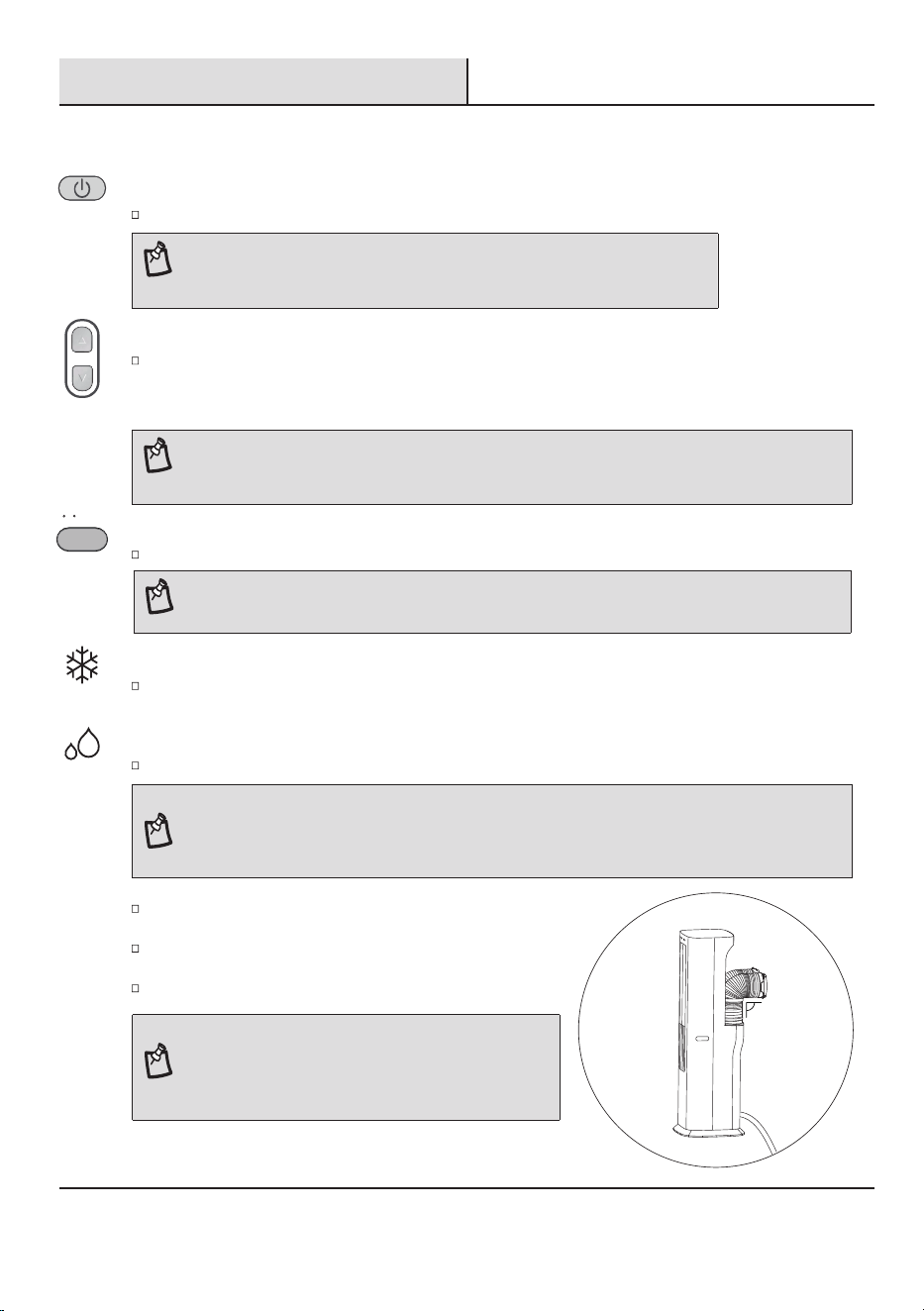
POWER ON OR OFF
NOTE:
When changing modes during operation, the unit may not respond immediately. Please be patient,
as the compressor needs 3 minutes to restart after shutting down.
Press ON/OFF button to turn on or off the unit.
COOL INDICATOR
Cooling-Cools the room. Press FAN to select AUTO, HIGH, MID or LOW.
Press the UP or DOWN button to adjust the temperature.
DRY INDICATOR
The air conditioner automatically selects the temperature. The fan runs on Low speed only.
NOTE:
In the Cooling and Heating mode, the temperature can be set between 61 °F and 86 °F (16 °C and 30 °C).
In Fan Only mode, the temperature cannot be set.
UP DOWN
Press the UP or DOWN button to set the temperature.
Press the UP button once to increase the set temperature by 1 °F (1 °C).
Press the DOWN button once to decrease the set temperature by 1 °F (1 °C).
MODE
Press MODE to select COOL, DRY, FAN or HEAT. (Heating is available only for heat pump models.)
NOTE:
Press the mode button for 5 seconds to switch the temperature display from degrees Fahrenheit(°F) to degrees Celsius(°C).
MODE
F / C [ 5 sec ]
NOTE:
Dry mode should not be used to cool the room.
During DRY mode, the indoor temperature may increase.
Keep windows and doors closed for the optimal dehumidification results.
Angle the flexible hoses to 90°, as shown. Do not connect the hoses to
the window kit.
Before starting the DRY mode, remove the drain cover and insert the
drain hose into the drain port. Refer to page 21 - "Care and Cleaning".
Direct the drain hose to a floor drain or a suitable drainage location.
90°
INDOOR
Drain Hose
NOTE:
The unit will not shut off automatically when using a external
water
container. To prevent overflow, check the water level of
the external water container regularly.
NOTE: Auto fan speed cannot be selected in Fan Only mode.
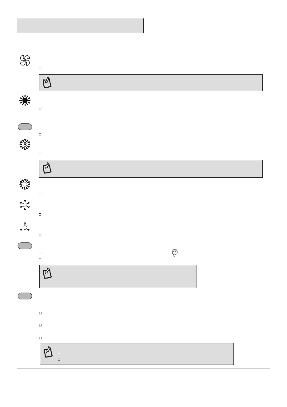
FAN ONLY INDICATOR
Fan Only-Only the fan runs. Press FAN button to adjust fan speed.
Operation (continued)
2
Using the Remote Control (continued)
18
AUTO FAN SPEED
NOTE:
Auto fan speed cannot be selected in Fan Only mode.
Auto-Automatically controls fan speed depending on current room temperature and setting temperature.
HIGH FAN SPEED
High for maximum fan speed.
MEDIUM FAN SPEED
LOW FAN SPEED
Low for minimum fan speed.
Mid for normal fan speed.
HEATING INDICATOR
FAN SPEED
Press and release FAN to choose the desired fan speed.
FAN
QUIET
Press the QUIET button to
set or cancel
the quiet mode, the indicator “ ” will display on LCD.
In this mode, the air conditioner will work with low noise performance.
NOTE:
It takes about 2 to 3 minutes to fully enter the quiet mode.
The QUIET button is disabled in dry mode.
QUIET
SUPER
Heating-Heats the room. Press FAN to select AUTO, HIGH, MID or LOW.
Press the UP or DOWN button to adjust the temperature.
SUPER
The SUPER button is used to start or stop fast cooling or fast heating.
NOTE:
In the SUPER mode, you can set the timer.
SUPER button is ineffective in ECO mode.
Pressing the SUPER button at cool, dry or fan only mode, fast cooling will automatically set the fan speed to High
and the temperature to 61 °F (16 °C).
If the model supports heating mode, you can use this button to turn on the fast heating function in heating mode.
Fast heating operates at auto fan speed or high speed, changing the set temperature automatically to 86 °F (30 °C).
You can turn off the super mode by pressing some keys such as SUPER, FAN, QUIET.
TIMER
Use the TIMER function to turn the air conditioner ON/OFF automatically.
Setting the Air Conditioner to Turn On:
Plug in the air conditioner and use the remote to power it ON.
Use the remote to set the desired mode, temperature, fan speed, etc.
Use the remote to power OFF the air conditioner.
Press TIMER on the remote and use the UP/ DOWN buttons to set the desired delay time.
Setting the Air Conditioner to Turn Off:
Plug in the air conditioner and use the remote to power it ON.
Use the remote to set the desired mode, temperature, fan speed, etc.
Press TIMER on the remote and use the UP/ DOWN buttons to set the desired delay time.
To Cancel Timer:
Press the TIMER button again. Once a “beep” is heard and the indicator disappears, the Timer mode has been canceled.
NOTE: The Timer mode can only be set by the remote control.
TIMER
DIMMER
Press the DIMMER button to turn off the control panel display.
NOTE: When in DIMMER mode, new control inputs will return display to normal.
DIMMER
Sleep [ 5 sec ]
NOTE: When the light is on, it will remain on for 180 hours or until you press Clean Filter button.
Operation (continued)
2
Using the Remote Control (continued)
19
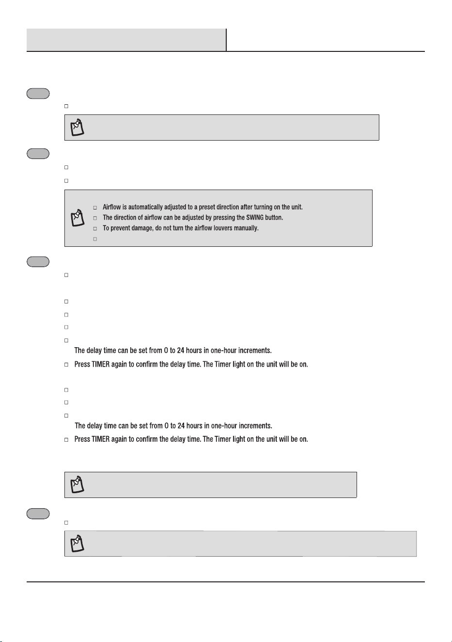
SWING
Press SWING once to change the horizontal airflow direction.
Press again to hold the louver in a desired position.
NOTE:
Turning the louver manually will disrupt normal operation. To recover, simply restart the air conditioner.
SWING
FILTER
Press FILTER button on remote to reset the filter cleaning tips after cleaning and replacing the air filter.
FILTER
Operation (continued)
SLEEP MODE
To turn off Sleep control, press MODE, FAN, SUPER, SLEEP or wait 8 hours for Sleep control to turn off automatically.
NOTE: The air conditioner will return to previous settings after Sleep mode is turned off.
Press and hold the DIMMER button on the remote for 5 seconds to switch the DIMMER mode to the Sleep mode.
After 10 seconds, the lights on the control panel display will dim.
NOTE:
Low speed.
Sleep mode can only be set in Cooling, Drying or Heating modes. When in sleep mode the unit will utilize lower, quieter
fan speeds and automatic temperature adjustments offering 8 hours of optimal sleeping conditions before shutting off.
DIMMER
Sleep [ 5 sec ]
2
Using the Remote Control (continued)
NOTE:
The appliance will stop operation automatically after operating for 8 hours.
Fan speed is automatically set at low speed.
Upon entering sleep mode, the appliance will automatically adjust
the temperature based on environmental conditions to ensure user comfort.
Sleep control cannot be selected in FAN mode.
3
Normal Sounds
When your air conditioner is operating normally, you may hear sounds such as:
1. Air movement from the fan.
2. Clicks from the thermostat cycling.
3. Vibration or noise due to poor wall or window construction.
4.
20
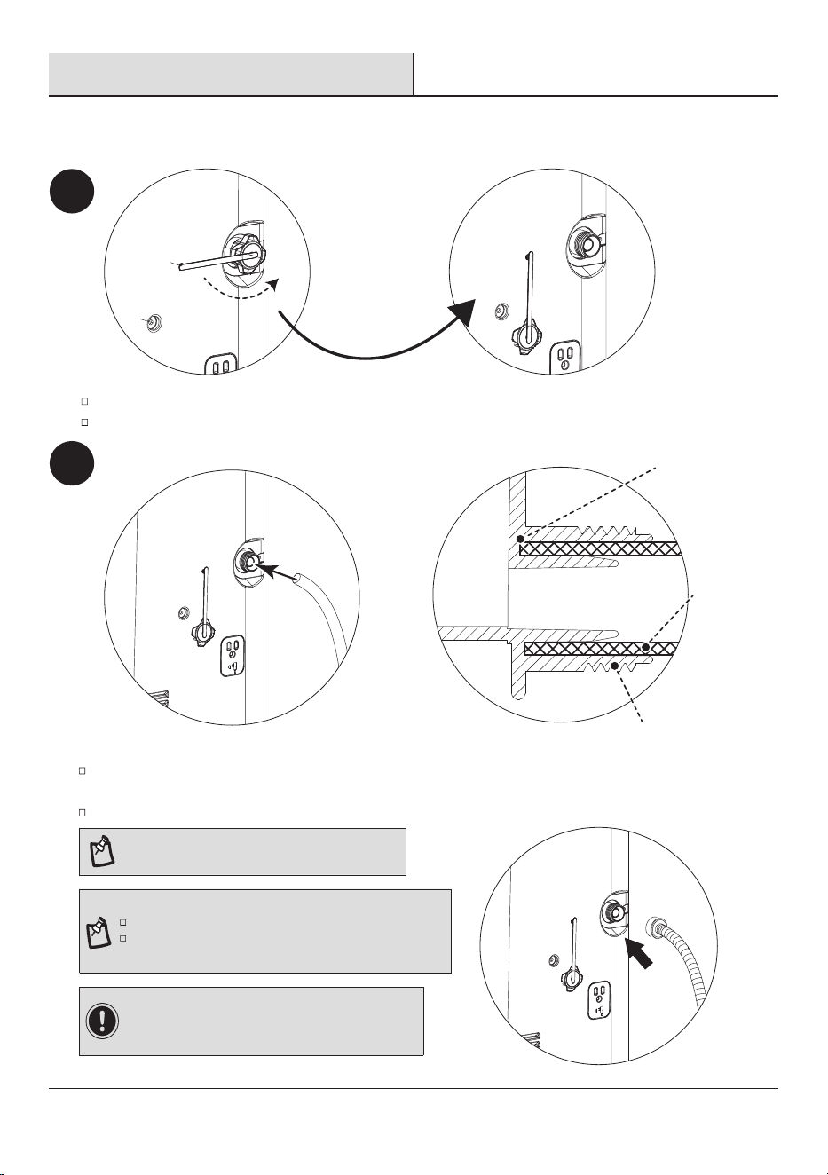
Scan to download the ConnectLife APP.
You can also go to Google Play or App Store and search for the ConnectLife APP.
Follow the in-APP instructions to pair your appliance.
The Connectlife app by Hisense provides you the ability to conveniently
monitor the unit and change your settings from anywhere.
DEVICES REQUIRED TO USE THE SMART AC:
Smartphone with compatible iOS or Android syste
m.
Wireless Router (a 2.4 GHz network is required to connect).
Smart air conditioner.
DOWNLOAD AND INSTALL THE CONNECTLIFE APP
4
Using the ConnectLife APP
NOTE: Only available on WiFi models.
Care and Cleaning
1
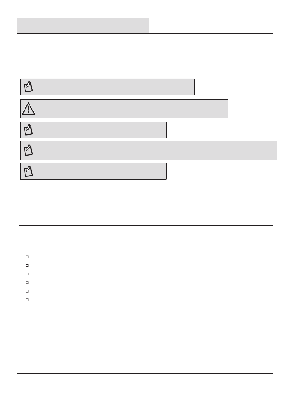
Draining the Air Conditioner
Turn off the air conditioner, then unplug it or disconnect it from the power source.
Remove the drain cover counterclockwise.
Completely drain the water through the drain port.
Attach the drain hose to the drain port (without screw thread).
Insert the hose into the bottom of the drain port securely.
Make sure the connector has no water leak.
21
NOTE: Garden hose is compatible with this model.
IMPORTANT: In North America the garden hose connectors
are 3/4 in. diameter straight (non-tapered) thread with a pitch
of 11.5 threads per inch (male part has an outer diameter of
1-1/16 in. (26.99 mm).
NOTE:
Garden hose sold separately.
The drain hose inner diameter should be greater than 1/2 in.
The connector is designed for North American garden hoses only.
1
2
Side view
The bottom
of drain
port
Drain hose
Drain port
22
Care and Cleaning (continued)
1
Draining the Air Conditioner
WARNING: Excessive Weight Hazard
Use two or more people to move and install the air conditioner. Failure to do so can result in back or other injury.
The unit will stop running after the water reaches warning level, carefully move the air conditioner to a drain location
or put the water collection tray at the bottom, then remove the drain cover and let the water drain away.
NOTE: To avoid leaking water from the unit, move the air conditioner slowly and keep it level.
NOTE: If the air conditioner will be stored after use, see “Storing After Use”.
NOTE:
Ensure proper water drainage prior to storage.
NOTE: For safe and continuous operation in Dry and Heating mode, ensure the drain hose is connected before turning on the unit.
Failure to do so may result in the unit shutting off automatically when the condensation level reaches a critical point.
2
Cleaning the Outside
Turn off the air conditioner.
Unplug air conditioner or disconnect power.
Remove the air filter and clean separately. See “Cleaning Air Filter”.
Wipe the outside of the air conditioner with a soft, damp cloth.
Plug in the air conditioner or reconnect power.
Start the air conditioner.
Care and Cleaning (continued)
NOTE:
chemical cleaner.
23
3
Cleaning the Air Filter
Turn off the air conditioner.
Start the air conditioner.
Reinstall the
Air Filter
.
There are three ports: A, , and C.
Please ensure that you insert
through port A.
4
Storing After se
If the air conditioner will not be used for an extended period of time:
Drain the water completely. See “Draining the Air Conditioner”.
Run the air conditioner set to Fan Only for approximately 12 hours to dry the air conditioner.
nplug the air conditioner.
Remove the window kit and store with the air conditioner in a clean, dry area. See “Installation Instructions”.
Clean the outside of the air conditioner. See “Cleaning the Outside”.
Remove the batteries and store the remote control with the air conditioner in a clean, dry area.
CAUTION: Please recycle or dispose of the packaging material for product in an environmentally responsible manner. Never store or ship the
air conditioner upside down or sideways to avoid damage to the compressor. Dispose of this appliance in accordance with Federal and ocal
regulations. Refrigerants must be evacuated before disposal.
efore using the air conditioner again:
Check the power cord to make sure it is in good condition, with no cracks or damage.
Place new batteries in the remote.
Install the air conditioner. See “Installation Instruction”.
Remove the Air Filter.
Air Filter
Port A
Port
Port C
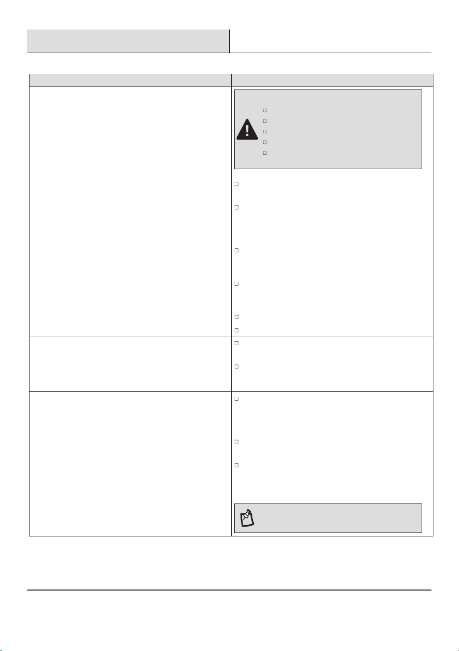
Troubleshooting
Before calling for service, please try the suggestion below.
Problem Solution
Air conditioner will not operate
DANGER: ELECTRICAL SHOCK HAZARD
Plug into a grounded 3-prong outlet.
Do not remove ground prong.
Do not use an adapter.
Do not use an extension cord.
Failure to follow these instructions can result in fire,
electrical shock,or death.
Air conditioner blo
ws fuses or trips circuit breakers
Too many appliances are being used on the same circuit. Unplug
or relocate appliances that share the same circuit.
You are trying to restart the air conditioner too soon after turn-
ing off air conditioner. Wait at least 3 minutes after turning off
air conditioner before trying to restart the air conditioner.
Air conditioner power supply cord trips (Reset button pops out)
Disturbances in your electrical current can trip (RESET button
will pop out) the power supply cord. Press and release RESET to
resume operation. (Listen for click; RESET button will latch and
remain in.)
Electrical overloading, overheating, cord pinching or aging can
trip (RESET button will pop out) the power supply cord.
After correcting the problem, press and release RESET to
resume operation. (Listen for click; RESET button will latch and
remain in.) If the power cord fails to reset, contact a service
technician.
NOTE: A damaged power supply cord must be replaced
with a new power supply cord obtained from the product
manufacturer and must not be repaired.
24
The power supply cord is unplugged. Plug into a grounded
3-prong outlet. See “Electrical Requirements” on page 8.
Time-delay fuse or circuit breaker of the wrong capacity is
being used. Replace with a time-delay fuse or circuit breaker
of the correct capacity. See “Electrical Requirements” on
page 8.
The power supply cord has tripped (Reset button has popped
out). Press and release RESET to resume operation. (Listen for
click; RESET button will latch and remain in.)
A household fuse has blown, or a circuit breaker has tripped.
Replace the fuse, or rest the circuit breaker. See “Electrical
Requirements” on page 8.
The On/Off button has not been pressed. Press ON/OFF.
The local power has failed. Wait for power to be restored.
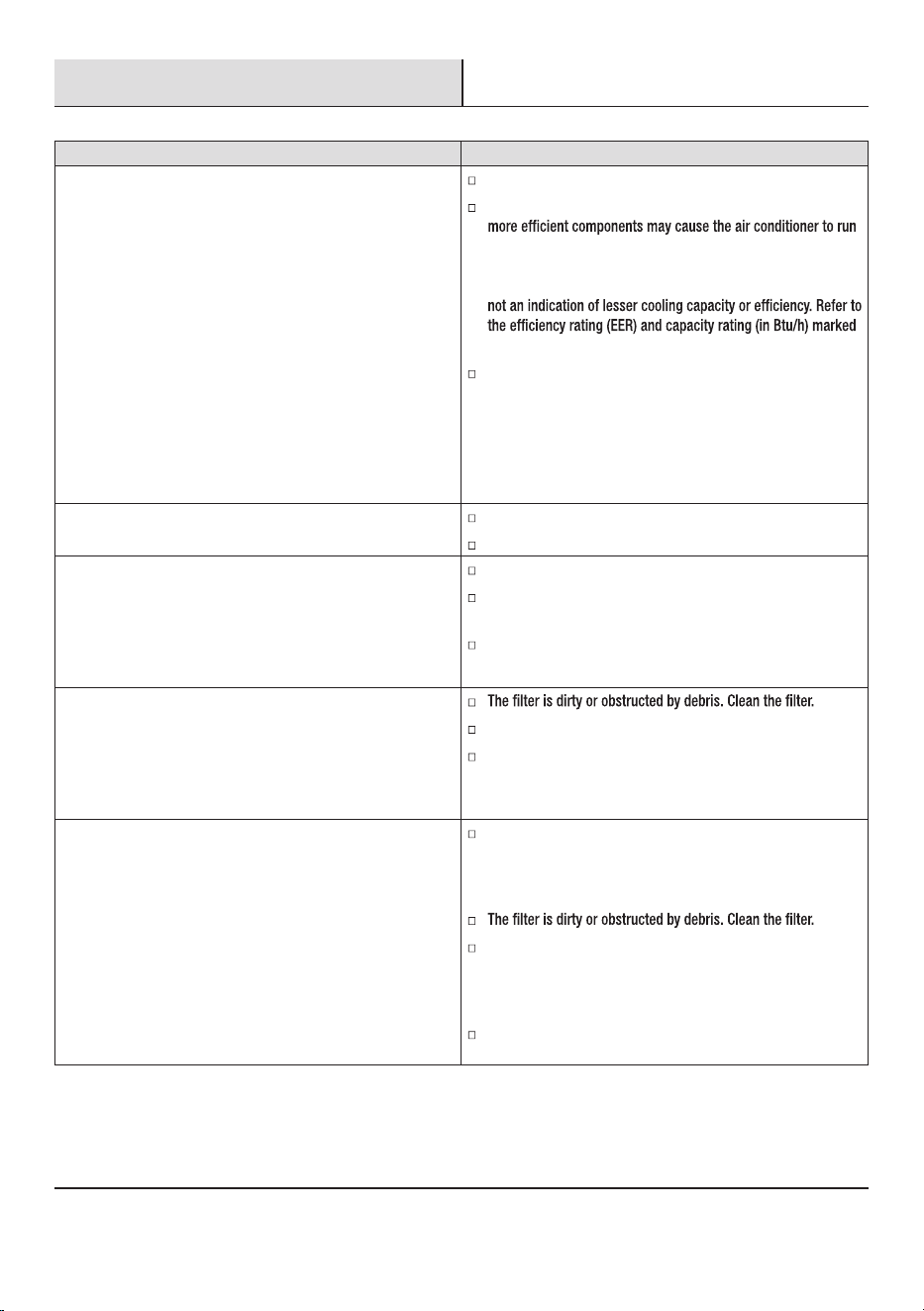
Troubleshooting (continued)
Problem Solution
Air conditioner seems to run too much
A door or window is open. Keep doors and windows closed.
The current air conditioner replaced an older model. The use of
longer than an older model, but the total energy consumption
will be less. Newer air conditioners do not emit the “blast” of
cold air you may be accustomed to from older units, but this is
on the air conditioner.
The air conditioner is in a heavily occupied room, or heat
producing appliances are in use in the room. Use exhaust vent
fans while cooking or bathing and try not to use heat-producing
appliances during the hottest part of the day. Portable air
conditioners are designed as supplemental cooling to local
areas within a room. A higher capacity air conditioner may be
required, depending on the size of the room being cooled.
Air conditioner runs for a short time only, but room is not cool
Set temperature is close to room temperature.
Lower set temperature. See “Operation”.
Display error code
Air conditioner runs, but does not cool
Air outlet is blocked. Clear air outlet.
Set temperature is too high. Lower set temperature.
Air conditioner cycles on and off too much
The air conditioner is not properly sized for your room. Check
the cooling capabilities of your portable air conditioner. Portable
air conditioners are designed as supplemental cooling to local
areas within a room.
There is excessive heat or moisture, open container cooking,
showers, etc. in the room. Use a fan to exhaust heat or moisture
from the room. Try not to use heat-producing appliances during
the hottest part of the day.
The louvers are blocked. Install the air conditioner in a location
where the louvers are free from curtains, blinds, furniture, etc.
25
If the unit displays error code E5, the water container is full.
Drain the water, see “Draining the Air Conditioner” on page
21. After draining, the unit can be operated again.
If the unit displays error code E1/E2/E3/E5/E6/E7/EA, please
contact customer service.

2427969-01