1
Majestic MARQ36IN-B, MARQ42IN-B Installation Manual • 2614-980 Rev. P • 5/22
Installation Manual
Installation and Appliance Setup
NOTICE: DO NOT discard this manual!
This appliance may be installed as an OEM
installation in manufactured home (USA
only) or mobile home and must be installed
in accordance with the manufacturer’s
instructions and the Manufactured Home
Construction and Safety Standard, Title 24
CFR, Part 3280 in the United States, or the
Standard for Installation in Mobile Homes,
CAN/CSA Z240 MH Series, in Canada.
This appliance is only for use with the type(s)
of gas indicated on the rating plate. This
appliance is not convertible for use with other
gases, unless a certied kit is used.
DANGER
HOT GLASS WILL
CAUSE BURNS.
DO NOT TOUCH GLASS
UNTIL COOLED.
NEVER ALLOW CHILDREN
TO TOUCH GLASS.
A barrier designed to reduce the risk of
burns from the hot viewing glass is provided
with this appliance and must be installed for
the protection of children and other at-risk
individuals.
• DO NOT store or use gasoline or other am-
mable vapors and liquids in the vicinity of this
or any other appliance.
• What to do if you smell gas
- DO NOT try to light any appliance.
- DO NOT touch any electrical switch. DO
NOT use any phone in your building.
- Leave the building immediately.
- Immediately call your gas supplier from
a neighbor’s phone. Follow the gas sup-
plier’s instructions.
- If you cannot reach your gas supplier, call
the re department.
• Installation and service must be performed
by a qualied installer, service agency, or the
gas supplier.
WARNING:
FIRE OR EXPLOSION HAZARD
Failure to follow safety warnings exactly
could result in serious injury, death, or
property damage.
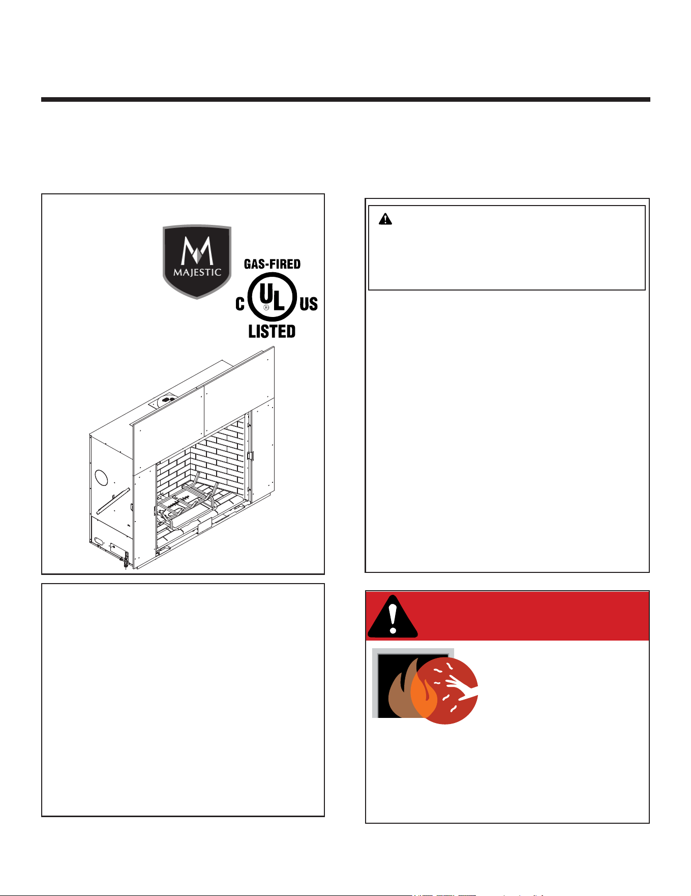
Models:
MARQ36IN-B, MARQ42IN-B
MARQUIS
SERIES
CAUTION! Risk of Fire! DO NOT store instruction manuals inside replace cavity.
High temperatures could cause a re.
INSTALLER: Leave this manual with the appliance, not inside the appliance.
CONSUMER: Retain this manual for future reference. Do not store inside the appliance.
Decorative barrier front provided with this appliance.
Pour demander un exemplaire en français de ce manuel
d’installation, visitez www.majesticproducts.com.

Majestic MARQ36IN-B, MARQ42IN-B Installation Manual • 2614-980 Rev. P • 5/222
Safety Alert Key:
• DANGER! Indicates a hazardous situation which, if not avoided will result in death or serious injury.
• WARNING! Indicates a hazardous situation which, if not avoided could result in death or serious injury.
• CAUTION! Indicates a hazardous situation which, if not avoided, could result in minor or moderate injury.
• NOTICE: Used to address practices not related to personal injury.
Table of Contents
Installation Standard Work Checklist .................... 3
1 Product Specic and Important Safety Information
A. Appliance Certication ............................4
B. Glass Specications .............................. 4
C. BTU Specications ............................... 4
D. High Altitude Installations .......................... 4
E. Non-Combustible Materials Specication. . . . . . . . . . . . . . 4
F. Combustible Materials Specication .................4
G. Electrical Codes .................................4
H. California ......................................4
I. Requirements for the Commonwealth of Massachusetts ..5
2 Getting Started
A. Design and Installation Considerations ...............6
B. Good Faith Wall Surface ..........................6
C. Tools and Supplies Needed ........................6
D. Inspect Appliance and Components ..................7
3 Framing and Clearances
A. Appliance/Decorative Barrier Front Dimension Diagrams . 8
B. Clearances to Combustibles ...................... 11
C. Constructing the Appliance Chase ..................13
D. Hearth Extension ............................... 15
E. Floor Protection ................................ 16
4 Termination Location and Vent Information
A. Approved Pipe .................................17
B. Vent Termination Minimum Clearances ..............17
C. Vent Terminal Clearances ........................18
E. Use of Elbows .................................19
F. Measuring Standards ............................20
G. Vent Diagrams .................................21
H. PVLP-SLP, PVI-SLP-B and PVV-SLP Information ......27
5 Vent Clearances and Framing
A. Pipe Clearances to Combustibles .................. 28
B. Wall Penetration Framing/Firestops .................28
C. Ceiling Firestop/Floor Penetration Framing ...........29
D. Install Attic Insulation Shield .......................29
E. Installing the Optional Heat Management ............ 30
6 Appliance Preparation
A. Vent Collar Preparation ..........................31
B. Securing and Leveling the Appliance ................32
C. Installing Non-Combustible Facing Material .......... 33
7 Venting and Chimneys
A. Assemble Vent Sections (DVP Pipe Only) ...........34
B. Assemble Slip Sections ..........................35
C. Secure the Vent Sections ......................... 36
D. Disassemble Vent Sections .......................36
E. Vertical Termination Requirements .................. 37
F. Horizontal Termination Requirements ...............38
8 Electrical Information
A. General Information .............................40
B. Wiring Requirements ............................42
9 Gas Information
A. Fuel Conversion ................................44
B. Gas Pressure ..................................44
C. Gas Connection ................................44
D. High Altitude Installations ......................... 44
E. Air Shutter Setting ..............................45
10 Finishing
A. Facing Material .................................46
B. Finishing Templates .............................47
C. Mantel and Wall Projections ....................... 49
D. Decorative Barrier Front Dimensions for Finishing. . . . . . 51
11 Appliance Setup
A. Fixed Glass Assembly ...........................52
B. Remove the Shipping Materials ...................54
C. Clean the Appliance ............................. 54
D. Refractory .....................................54
E. Lava Rock Placement ...........................54
F. Glowing Ember Placement ........................54
G. Teco-Sil Placement .............................55
H. Log Set Assembly ..............................56
I. IntelliFire Touch Control System Setup ..............64
J. LED’s .........................................64
K. Install Decorative Barrier Front. . . . . . . . . . . . . . . . . . . . . 64
12 Reference Materials
A. Vent Components Diagrams ...................... 65
B. Accessories ...................................71
= Contains updated information.
Note: The term “recommend” or “recommended” does not indicate a requirement. It is a best practice suggested by
Hearth & Home Technologies
®
.
3
Majestic MARQ36IN-B, MARQ42IN-B Installation Manual • 2614-980 Rev. P • 5/22
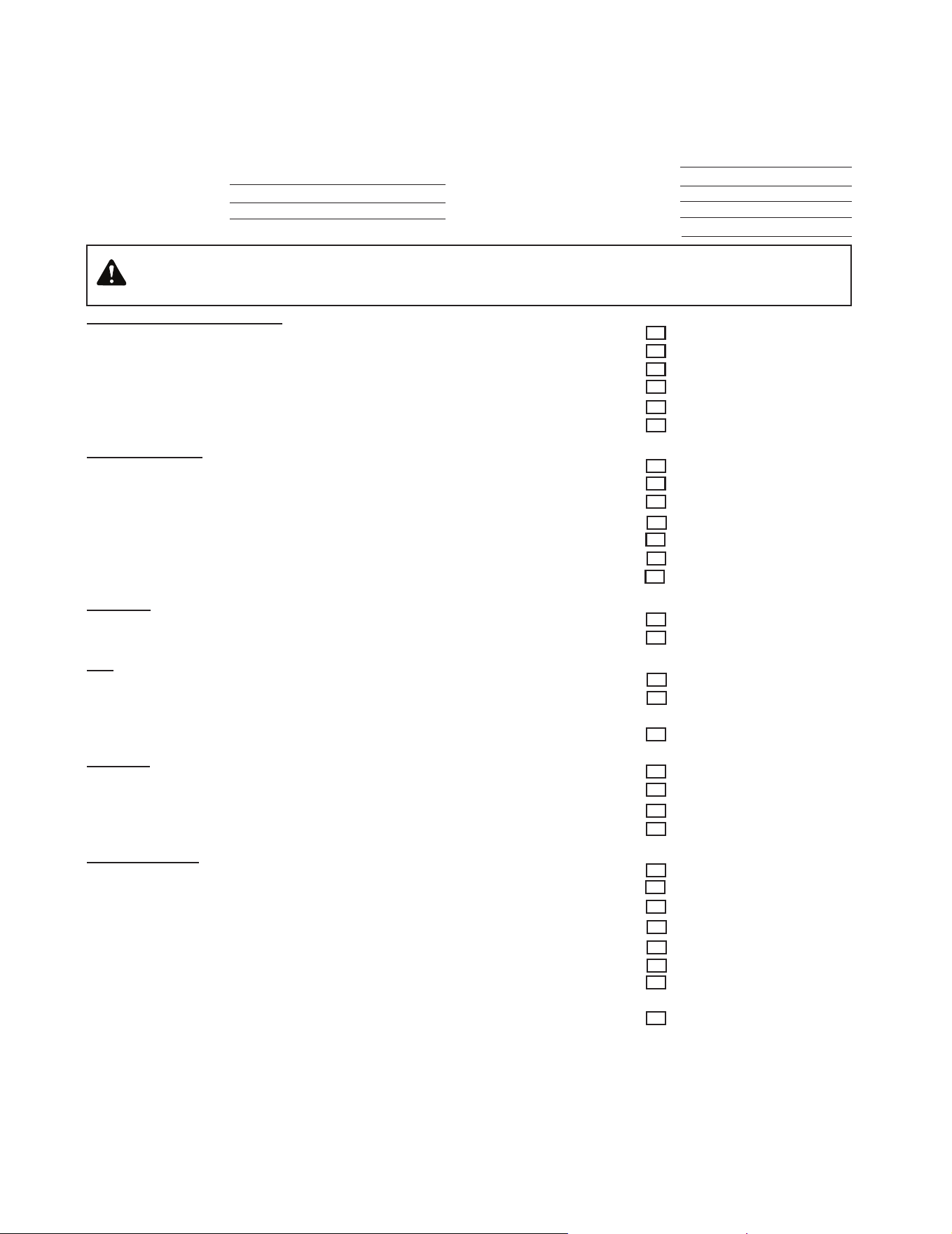
Installation Standard Work Checklist
Customer:
Lot/Address:
Model (circle one): MARQ36IN-B, MARQ42IN-B
Date Installed:
Location of Fireplace:
Installer:
Dealer/Distributor Phone #
Serial #:
Comments Communicated to party responsible ____________________ by ______________________on ___________
(Builder / Gen. Contractor/) (Installer) (Date)
Î = Contains updated information.
Hearth & Home Technologies recommends the following:
• Photographing the installation and copying this checklist for your le.
• That this checklist remain visible at all times on the appliance until the installation is complete.
This standard work checklist is to be used by the installer in conjunction with, not instead of, the instructions contained in
this installation manual.
WARNING! Risk of Fire or Explosion! Failure to install appliance according to these instructions can lead to a
re or explosion. Install ONLY components and accessories approved by Hearth & HOme Technologies. Unap-
proved components and accessories could cause replace to overheat.
ATTENTION INSTALLER:
Follow this Standard Work Checklist
Appliance Install Information YES IF NO, WHY?
Veri ed clearances to combustibles requirements are maintained. (Pg. 11-12) ___________________
Veri ed that the chase is insulated and sealed. (Pg. 13) ___________________
Veri ed mantel and wall clearance requirements are maintained. (Pg. 49-50) ___________________
Veri ed hearth extension requirements are maintained. (Pg. 15-16) ___________________
Veri ed appliance is leveled and secured. (Pg. 32) ___________________
Veri ed required factory-supplied non-combustible board installed. (Pg. 33) ___________________
Venting/Chimney Section 7 (Pg. 34-39)
Veri ed venting con guration complies to vent diagrams. ___________________
Veri ed venting installed, locked and sealed/secured in place. ___________________
Veri ed venting meets clearance to combustible requirements. ___________________
Veri ed wall/ceiling restops are installed (if applicable). ___________________
Veri ed attic insulation shield is installed (if applicable). ___________________
Veri ed Exterior wall/Roof ashing is installed and sealed. ___________________
Veri ed termination cap is installed and sealed. ___________________
Electrical Section 8 (Pg. 40-43)
Veri ed unswitched power (110-120 VAC) provided to the appliance. ___________________
Veri ed wall switch wires are properly installed (if applicable). ___________________
Gas Section 9 (Pg. 44-45)
Veri ed appliance is using proper fuel type. ___________________
If converted, veri ed proper fuel conversion kit was used. ___________________
Veri ed that gas components ( ttings, pressure taps, etc) are leak free and replace is
operating under correct pressures. ___________________
Finishing Section 10 (Pg. 46-51)
Veri ed that nish material does not interfere with install/operation of decorative barrier front ___________________
Veri ed combustible materials are not installed in non-combustible areas. ___________________
Veri ed all clearances meet installation manual requirements. ___________________
Veri ed mantels/wall projections comply with installation manual requirements. ___________________
Appliance Setup Section 11 (Pg. 55-64)
Veri ed all packaging and protective materials are removed (inside & outside of appliance). ___________________
Veri ed Teco-Sil installed and properly fogged with black high temperature paint. ___________________
Veri ed Lava Rock, Mystic Embers, Glowing Embers, and logs installed correctly. ___________________
Veri ed xed glass assembly installed and secured. ___________________
Veri ed that a required decorative door option is installed properly. ___________________
Veri ed remote control has been programmed and is fully functional. ___________________
Veri ed proper air shutter setting for installation type and vent con guration. ___________________
Manual bag and all of its contents are removed from inside/under
the appliance and given to party responsible for use and operation. ___________________
2614-982B 11/21
Comments: Further description of the issues, who is responsible (Installer/ Builder/ Other Trades, etc) and corrective
action needed ____________________________________________________________________________________
Majestic MARQ36IN-B, MARQ42IN-B Installation Manual • 2614-980 Rev. P • 5/224
This product is listed to ANSI standards for “Vented Gas
Fireplace Heaters” and applicable sections of “Gas Burn-
ing Heating Appliances for Manufactured Homes and
Recreational Vehicles”, and “Gas Fired Appliances for
Use at High Altitudes”.
A. Appliance Certication D. High Altitude Installations
NOTICE: If the heating value of the gas has been reduced,
these rules do not apply. Check with your local gas utility
or authorities having jurisdiction.
When installing above 2000 feet elevation:
• In the USA: Reduce input rate 4% for each 1000 feet
above 2000 feet.
• In CANADA: Input ratings are certied without a
reduction of input rate for elevations up to 4500 feet
(1370 m) above sea level. Please consult provincial
and/or local authorities having jurisdiction for installa-
tions at elevations above 4500 feet (1370 m).
Check with your local gas utility to determine proper
orice size.
E. Non-Combustible Materials Specication
Material which will not ignite and burn. Such materials are
those consisting entirely of steel, iron, brick, tile, concrete,
slate, glass or plasters, or any combination thereof.
Materials that are reported as passing ASTM E 136,
Standard Test Method for Behavior of Materials in
a Vertical Tube Furnace at 750 ºC shall be considered
non-combustible materials.
F. Combustible Materials Specication
Materials made of or surfaced with wood, compressed pa-
per, plant bers, plastics, or other material that can ignite
and burn, whether ame proofed or not, or plastered or
unplastered shall be considered combustible materials.
G. Electrical Codes
NOTICE: This appliance must be electrically wired
and grounded in accordance with local codes or, in the
absence of local codes, with National Electric Code
ANSI/NFPA 70-latest edition or the Canadian Electric
Code CSA C22.1.
• A 110-120 VAC circuit for this product must be pro-
tected with ground-fault circuit-interrupter protection,
in compliance with the applicable electrical codes,
when it is installed in locations such as in bathrooms
or near sinks.
NOT INTENDED FOR USE AS A PRIMARY HEAT SOURCE.
This appliance is tested and approved as either supplemen-
tal room heat or as a decorative appliance. It should not be
factored as primary heat in residential heating calculations.
NOTICE: This installation must conform with local codes.
In the absence of local codes you must comply with the
National Fuel Gas Code, ANSI Z223.1-latest edition in
the U.S.A. and the CAN/CGA B149 Installation Codes in
Canada.
1 1
Product Specic and Important Safety Information
B. Glass Specications
This appliance is equipped with ceramic glass with an
anti-reective coating. Replace glass only with ceramic
glass. Please contact your dealer for replacement glass.
MODELS: MARQ36IN-B, MARQ42IN-B
LABORATORY: Underwriters Laboratories, Inc. (UL)
TYPE: Direct Vent Heater
STANDARD: ANSI Z21.88-2019 • CSA 2.33-2019
C. BTU Specications
Models
(U.S. or Canada)
Maximum
Input
BTU/h
Minimum
Input
BTU/h
Orice
Size
(DMS)
MARQ36IN-B (NG)
(0-2000 FT)
44,000 25,000 #30
MARQ36IN-B
(Propane)
(0-2000 FT)
43,500 24,000 #47
MARQ42IN-B (NG)
(0-2000 FT)
54,500 30,000 #26
MARQ42IN-B
(Propane)
(0-2000 FT)
47,500 23,500 #45
H. California
WARNING: This product and the fuels used to
operate this product (liquid propane or natural
gas), and the products of combustion of such fuels, can
expose you to chemicals including benzene, which is
known to the State of California to cause cancer and
reproductive harm. For more information go to: www.
P65Warnings.ca.gov.

5
Majestic MARQ36IN-B, MARQ42IN-B Installation Manual • 2614-980 Rev. P • 5/22
I. Requirements for the Commonwealth of
Massachusetts
For all side wall horizontally vented gas fueled equipment
installed in every dwelling, building or structure used in
whole or in part for residential purposes, including those
owned or operated by the Commonwealth and where the
side wall exhaust vent termination is less than seven (7)
feet above nished grade in the area of the venting, in-
cluding but not limited to decks and porches, the following
requirements shall be satised:
Installation of Carbon Monoxide Detectors
At the time of installation of the side wall horizontal vented
gas fueled equipment, the installing plumber or gas tter
shall observe that a hard wired carbon monoxide detector
with an alarm and battery back-up is installed on the oor
level where the gas equipment is to be installed. In addi-
tion, the installing plumber or gas tter shall observe that
a battery operated or hard wired carbon monoxide detec-
tor with an alarm is installed on each additional level of
the dwelling, building or structure served by the side wall
horizontal vented gas fueled equipment. It shall be the
responsibility of the property owner to secure the services
of qualied licensed professionals for the installation of
hard wired carbon monoxide detectors.
In the event that the side wall horizontally vented gas fu-
eled equipment is installed in a crawl space or an attic,
the hard wired carbon monoxide detector with alarm and
battery back-up may be installed on the next adjacent
oor level.
In the event that the requirements of this subdivision can
not be met at the time of completion of installation, the
owner shall have a period of thirty (30) days to comply
with the above requirements; provided, however, that dur-
ing said thirty (30) day period, a battery operated carbon
monoxide detector with an alarm shall be installed.
Approved Carbon Monoxide Detectors
Each carbon monoxide detector as required in accor-
dance with the above provisions shall comply with NFPA
720 and be ANSI/UL 2034 listed and IAS certied.
Signage
A metal or plastic identication plate shall be permanent-
ly mounted to the exterior of the building at a minimum
height of eight (8) feet above grade directly in line with the
exhaust vent terminal for the horizontally vented gas fu-
eled heating appliance or equipment. The sign shall read,
in print size no less than one-half (1/2) in. in size, “GAS
VENT DIRECTLY BELOW. KEEP CLEAR OF ALL OB-
STRUCTIONS”.
Inspection
The state or local gas inspector of the side wall horizon-
tally vented gas fueled equipment shall not approve the
installation unless, upon inspection, the inspector ob-
serves carbon monoxide detectors and signage installed
in accordance with the provisions of 248 CMR 5.08(2)(a)1
through 4.
Exemptions
The following equipment is exempt from 248 CMR 5.08(2)
(a)1 through 4:
• The equipment listed in Chapter 10 entitled “Equipment
Not Required To Be Vented” in the most current edition
of NFPA 54 as adopted by the Board; and
• Product Approved side wall horizontally vented gas fu-
eled equipment installed in a room or structure separate
from the dwelling, building or structure used in whole or
in part for residential purposes.
MANUFACTURER REQUIREMENTS
Gas Equipment Venting System Provided
When the manufacturer of Product Approved side wall
horizontally vented gas equipment provides a venting
system design or venting system components with the
equipment, the instructions provided by the manufacturer
for installation of the equipment and the venting system
shall include:
• Detailed instructions for the installation of the venting
system design or the venting system components; and
• A complete parts list for the venting system design or
venting system.
Gas Equipment Venting System NOT Provided
When the manufacturer of a Product Approved side wall
horizontally vented gas fueled equipment does not pro-
vide the parts for venting the ue gases, but identies
“special venting systems”, the following requirements
shall be satised by the manufacturer:
• The referenced “special venting system” instructions
shall be included with the appliance or equipment in-
stallation instructions; and
• The “special venting systems” shall be Product Ap-
proved by the Board, and the instructions for that sys-
tem shall include a parts list and detailed installation
instructions.
A copy of all installation instructions for all Product Ap-
proved side wall horizontally vented gas fueled equip-
ment, all venting instructions, all parts lists for venting
instructions, and/or all venting design instructions shall
remain with the appliance or equipment at the completion
of the installation.
See Gas Connection section for additional Common-
wealth of Massachusetts requirements.
Note: The following requirements reference various
Massachusetts and national codes not contained in this
document.
Majestic MARQ36IN-B, MARQ42IN-B Installation Manual • 2614-980 Rev. P • 5/226
2 2
Getting Started
A. Design and Installation Considerations
WARNING! Risk of Fire or Explosion! Read all instruc-
tions before starting the installation.
Direct vent gas appliances are designed to operate with
all combustion air siphoned from outside of the building
and all exhaust gases expelled to the outside. No addi-
tional outside air source is required.
Installation MUST comply with local, regional, state and
national codes and regulations. Consult insurance carrier,
local building inspector, re ofcials or authorities having
jurisdiction over restrictions, installation inspection and
permits.
Before installing, determine the following:
• Where the appliance is to be installed.
• The vent system conguration to be used.
• Gas supply piping requirements.
• Provisions for optional heat management system.
• Electrical wiring requirements.
• Framing and nishing details.
• Whether optional accessories—devices such as a fan,
wall switch, or remote control—are desired.
C. Tools and Supplies Needed
Before beginning the installation be sure that the following
tools and building supplies are available.
Hand Tools Tape measure
Level Framing material
Manometer Framing square
Voltmeter Electric drill and bits (1/4 in.)
Plumb line Safety glasses/Gloves
Wrenches Reciprocating saw
1/4 in. nut driver
Non-corrosive leak check solution
1/2 - 3/4 in. length, #6 or #8 Self-drilling screws
Caulking material (300 ºF minimum continuous exposure
rating)
Improper installation, adjustment, alteration, service or
maintenance can cause injury or property damage. For
assistance or additional information, consult a qualied
service technician, service agency or your dealer.
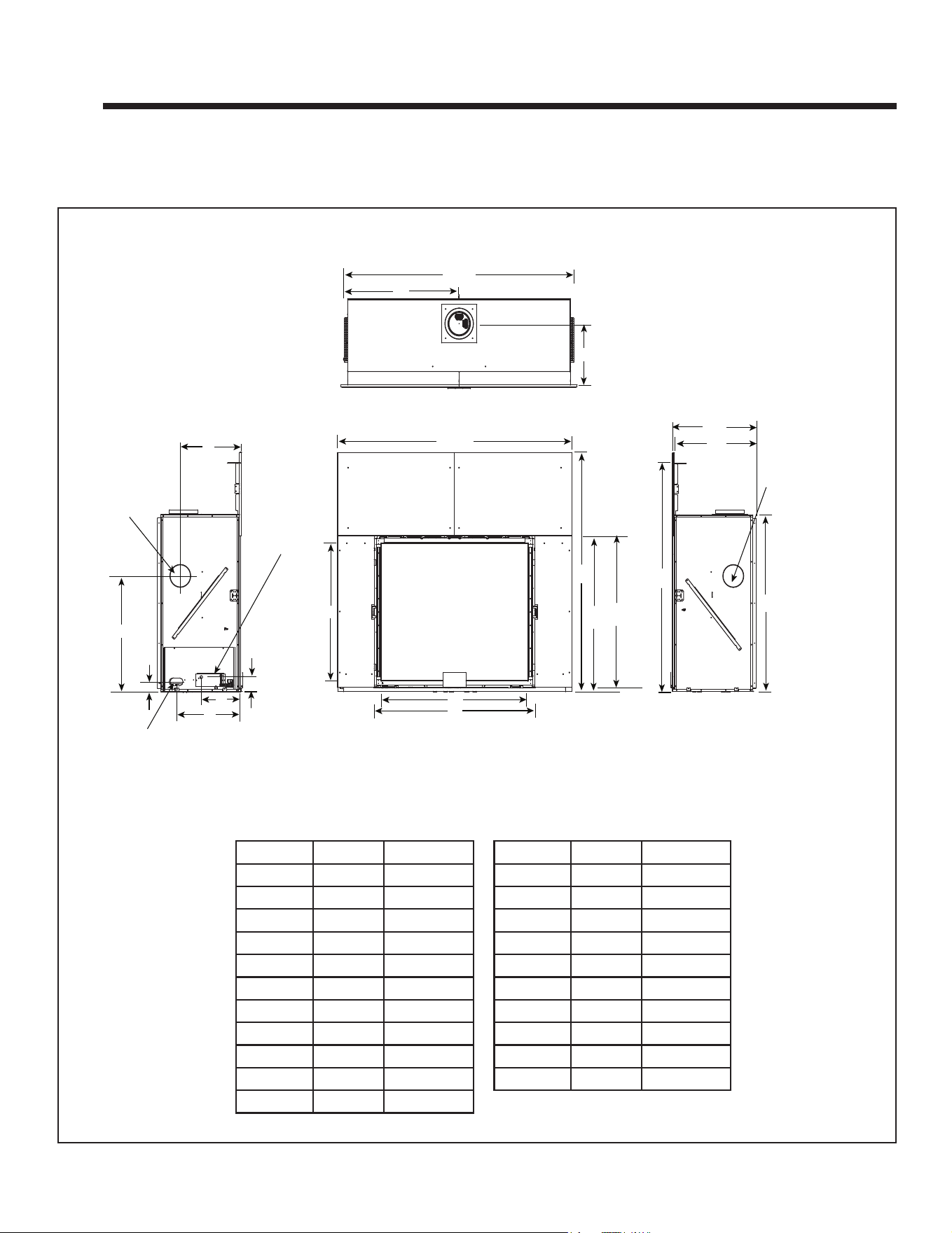
Figure 2.1 Good Faith Wall Surface Temperatures Above Appliance
B. Good Faith Wall Surface
NOTICE: Surface temperatures listed above are taken with
a temperature measuring probe as prescribed by the test
standard used for appliance certication. Temperatures
on walls or mantels taken with an infrared thermometer
may yield increased temperatures of up to 30 °F (17 °C) or
more depending on the thermometer settings and material
characteristics being measured. Use appropriate nishing
materials that are able to withstand these conditions. For
additional nishing guidelines, see Section 10.
MEASUREMENTS FROM
TOP EDGE OF THE OPENING
22 IN.
34 IN.
40 IN.
46 IN.
52 IN. MIN.
CEILING
28 IN.
APPLIANCE FRONT
FIREPLACE OPENING
165°F+
150°F
160°F
155°F
160°F
16 IN.
180°F+
10 IN.
230°F+
Installation and service of this appliance should be performed by
qualied personnel. Hearth & Home Technologies recommends
HHT Factory Trained or NFI certied professionals.
If installing a television (TV) above the appliance, see
Section 3 of the appliance Owner’s Manual.

7
Majestic MARQ36IN-B, MARQ42IN-B Installation Manual • 2614-980 Rev. P • 5/22
D. Inspect Appliance and Components
• Carefully remove the appliance and components from
the packaging.
• The vent system components and decorative barrier
fronts may be shipped in separate packages.
• If packaged separately, the log set and appliance grate
must be installed.
• Report to your dealer any parts damaged in shipment,
particularly the condition of the glass.
• This product is factory-equipped with an IntelliFire Touch
remote control, which was paired to the appliance at the
factory. This specic remote control needs to remain with
the contents of the manual bag. Do not install batteries
in the remote control until performing the nal appliance
setup and checklist.
• Read all of the instructions before starting the instal-
lation. Follow these instructions carefully during the
installation to ensure maximum safety and benet.
WARNING! Risk of Fire or Explosion! Damaged parts
could impair safe operation. DO NOT install damaged, in-
complete or substitute components. Keep appliance dry.
Hearth & Home Technologies disclaims any responsibility for,
and the warranty will be voided by, the following actions:
• Installation and use of any damaged appliance or vent system
component.
• Modication of the appliance or vent system.
• Installation other than as instructed by Hearth & Home
Technologies.
• Improper positioning of the gas logs or the glass assembly.
• Installation and/or use of any component part not approved
by Hearth & Home Technologies.
Any such action may cause a re hazard.
WARNING! Risk of Fire, Explosion or Electric Shock!
DO NOT use this appliance if any part has been under
water. Call a qualied service technician to inspect the
appliance and to replace any part of the control system
and/or gas control which has been under water.
Majestic MARQ36IN-B, MARQ42IN-B Installation Manual • 2614-980 Rev. P • 5/228
3 3
Framing and Clearances
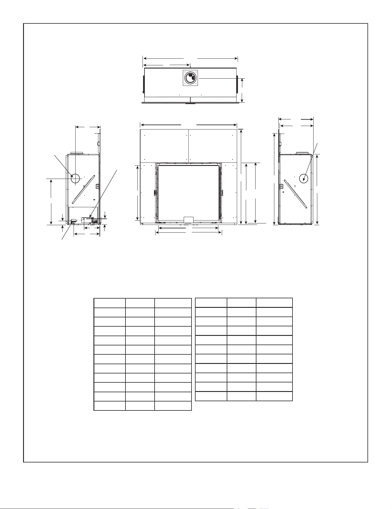
A. Appliance/Decorative Barrier Front Dimension Diagrams
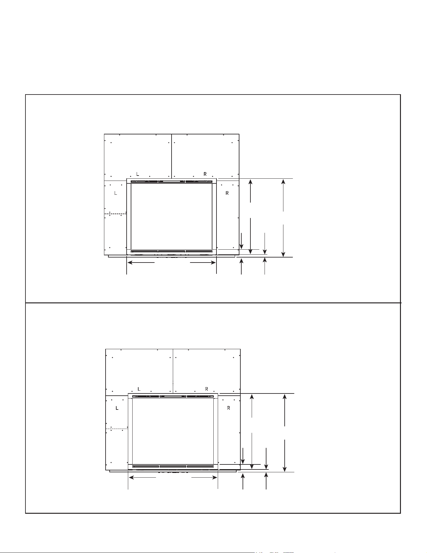
Dimensions are actual appliance dimensions. Use for reference only. For framing dimensions and clearances refer to Section 5.
Figure 3.1 Appliance Dimensions (MARQ36IN-B)
Appliance Dimensions Table MARQ36IN-B
A
B
D
C
E
I
L
M
N
O
P
R
Q
GAS
ACCESS
ELECTRICAL
ACCESS
J
K
HEAT MANAGMENT
SYSTEMS ACCESS
(BOTH SIDES)
S (diameter)
H
F
G
T
U
HEAT MANAGMENT
SYSTEMS ACCESS
(BOTH SIDES)
S (diameter)
APPLIANCE DIMENSION DIAGRAM (MARQ36IN-B)
Location Inches Millimeters
L 59-1/4 1505
M 16 406
N 29-5/8 752
O 3-7/8 98
P 2-3/4 70
Q 10-7/8 276
R 16-1/8 410
S 6 152
T 16-7/8 429
U 25-5/8 651
Location Inches Millimeters
A 61 1549
B 35-7/8 911
C 39-7/8 1013
D 31-1/16 789
E 57-5/8 1464
F 35-3/16 894
G 34-3/16 868
H 54-15/16 1395
I 41-3/8 1051
J 24 610
K 23-1/2 597
9
Majestic MARQ36IN-B, MARQ42IN-B Installation Manual • 2614-980 Rev. P • 5/22
A
B
D
C
E
I
L
M
N
O
P
R
Q
GAS
ACCESS
ELECTRICAL
ACCESS
J
K
HEAT MANAGMENT
SYSTEMS ACCESS
(BOTH SIDES)
S (diameter)
H
F
G
T
U
HEAT MANAGMENT
SYSTEMS ACCESS
(BOTH SIDES)
S (diameter)
Appliance Dimensions Table MARQ42IN-B
Figure 3.2 Appliance Dimensions (MARQ42IN-B)
APPLIANCE DIMENSION DIAGRAM (MARQ42IN-B)
Location Inches Millimeters
L 65-5/16 1659
M 16 406
N 32-11/16 830
O 3-7/8 98
P 2-3/4 70
Q 10-7/8 276
R 16-1/8 410
S 6 152
T 16-7/8 429
U 30-5/8 778
Location Inches Millimeters
A 67 1702
B 41-7/8 1064
C 45-7/8 1165
D 36-1/16 916
E 62-5/8 1591
F 40-3/16 1021
G 39-3/16 995
H 59-15/16 1522
I 46-3/8 1178
J 24 610
K 23-1/2 597
Majestic MARQ36IN-B, MARQ42IN-B Installation Manual • 2614-980 Rev. P • 5/2210
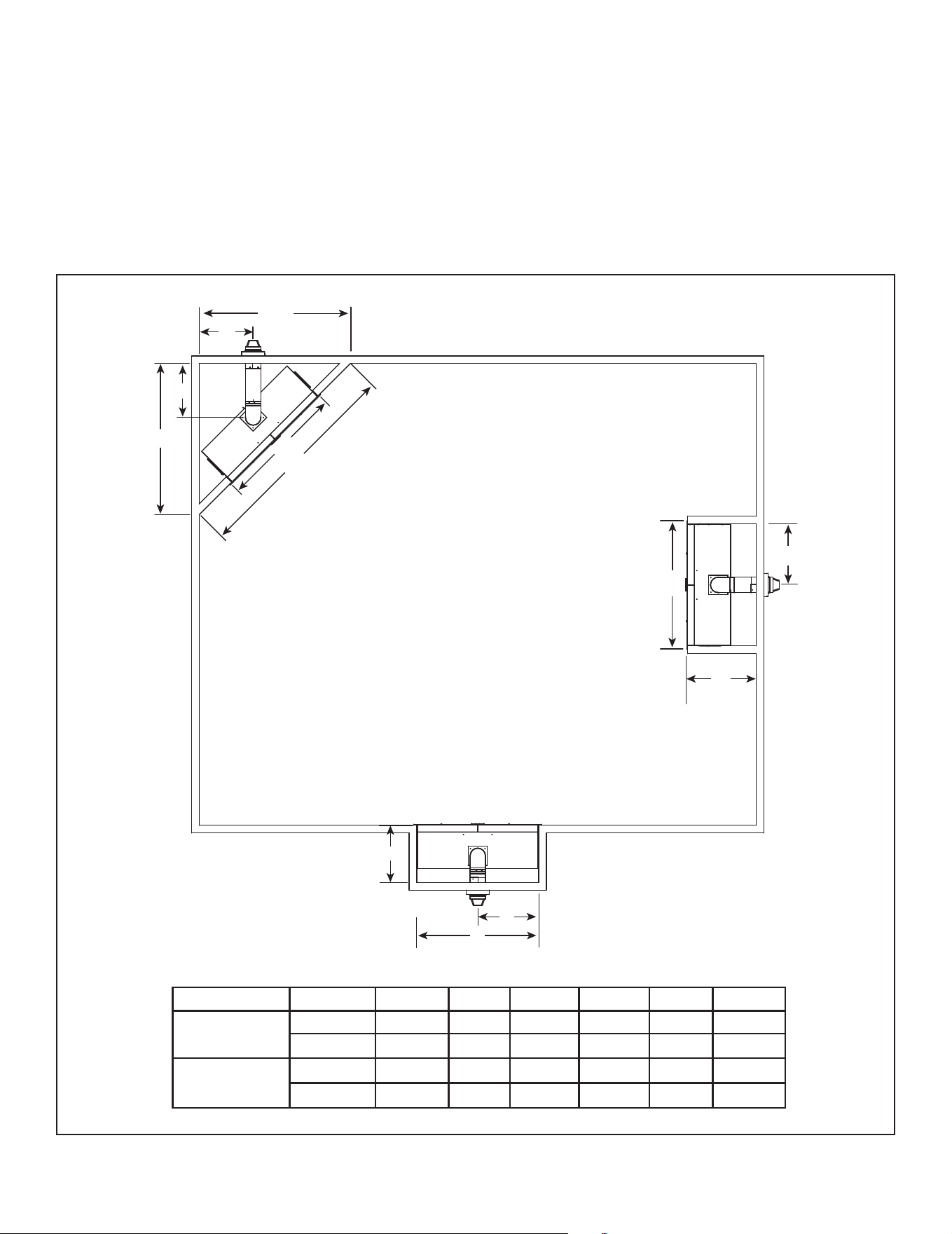
DECORATIVE BARRIER FRONT DIMENSION DIAGRAM
Figure 3.3 Decorative Barrier Front Dimensions
Note: See Section 10 for hearth, mantel and nishing detail.
1-5/16 IN.
(33 mm)
3-5/8 IN.
(92 mm)
40-11/16 IN.
(1033 mm)
36-13/16 IN.
(935 mm)
35-9/16 IN.
(903 mm)
FSMQ36
MARQ36IN-B
1-1/4 IN.
(32 mm)
3-9/16 IN.
(91 mm)
46-11/16 IN.
(1186 mm)
41-13/16 IN.
(1062 mm)
40-9/16 IN.
(1030 mm)
FSMQ42
MARQ42IN-B
IMPORTANT! This replace requires an installed decorative barrier front to prevent direct contact with the hot
viewing glass. DO NOT operate the replace with the barrier removed.
Decorative barrier front must be ordered at time of replace purchase. If decorative barrier front is not present,
contact dealer.
11
Majestic MARQ36IN-B, MARQ42IN-B Installation Manual • 2614-980 Rev. P • 5/22
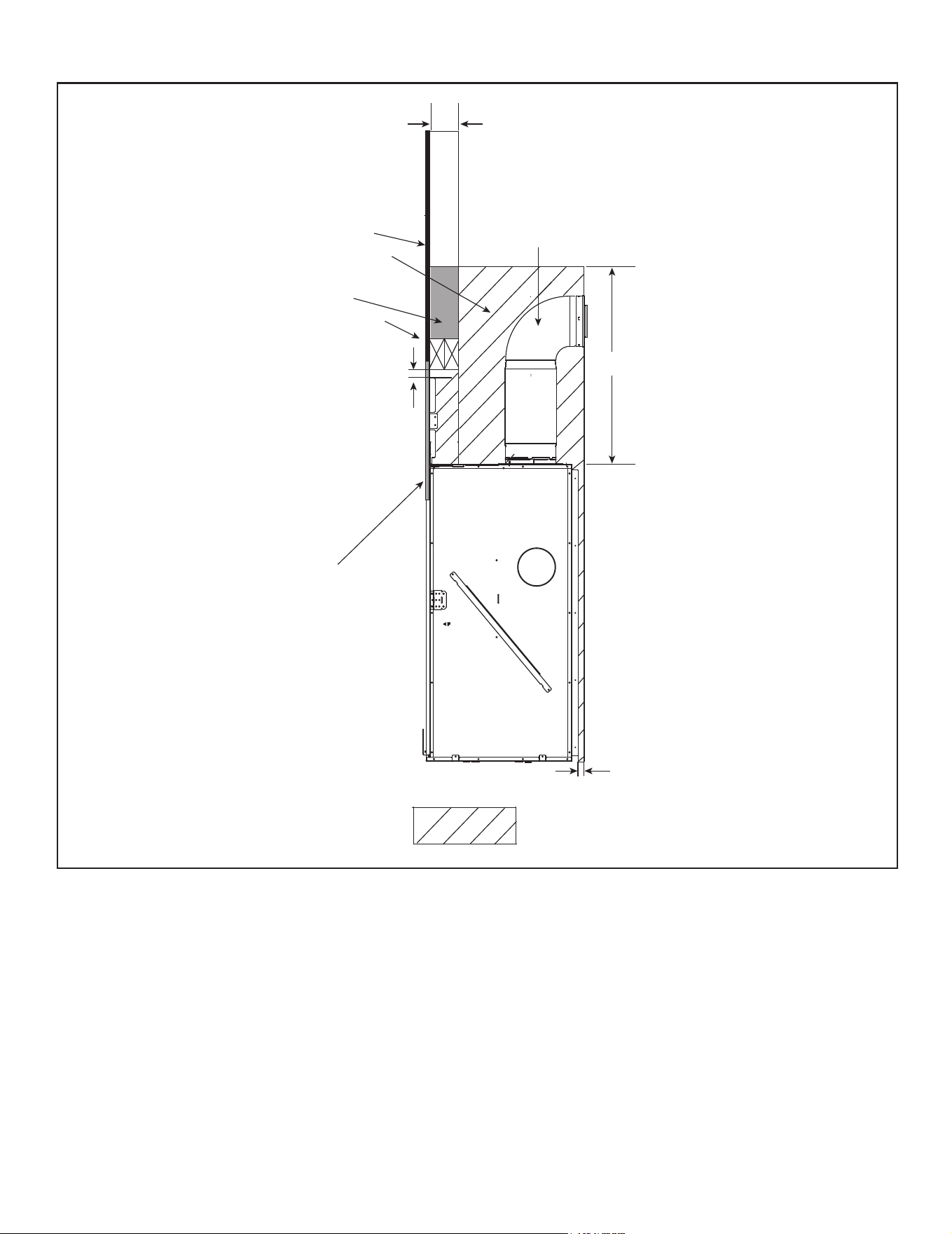
B. Clearances to Combustibles
When selecting a location for the appliance it is important
to consider the required clearances to walls and allow suf-
cient clearance for heat management systems venting.
See Figure 3.3 and Figure 3.4.
WARNING! Risk of Fire or Burns! Provide adequate
clearance around air openings and for service access.
Due to high temperatures, the appliance should be lo-
cated out of trafc and away from furniture and draperies.
NOTICE: Illustrations reect typical installations and are
FOR DESIGN PURPOSES ONLY. Illustrations/diagrams
are not drawn to scale. Actual installation may vary due to
individual design preference.
Figure 3.4 Appliance Locations
A
B
C
D
E
F
B
F
B
E
D
A
Note: Dimensions below refer to a framed wall on
which 1/2 inch wall sheathing has not been installed.
A B C D E F
MARQ36IN-B
Inches 75-5/16 59-1/2 106-1/2 26-3/8 24 29-3/4
Millimeters 1913 1511 2705 670 610 756
MARQ42IN-B
Inches 79-5/8 65-9/16 112-9/16 28-1/2 24 32-13/16
Millimeters 1921 1665 2859 724 610 833
Majestic MARQ36IN-B, MARQ42IN-B Installation Manual • 2614-980 Rev. P • 5/2212
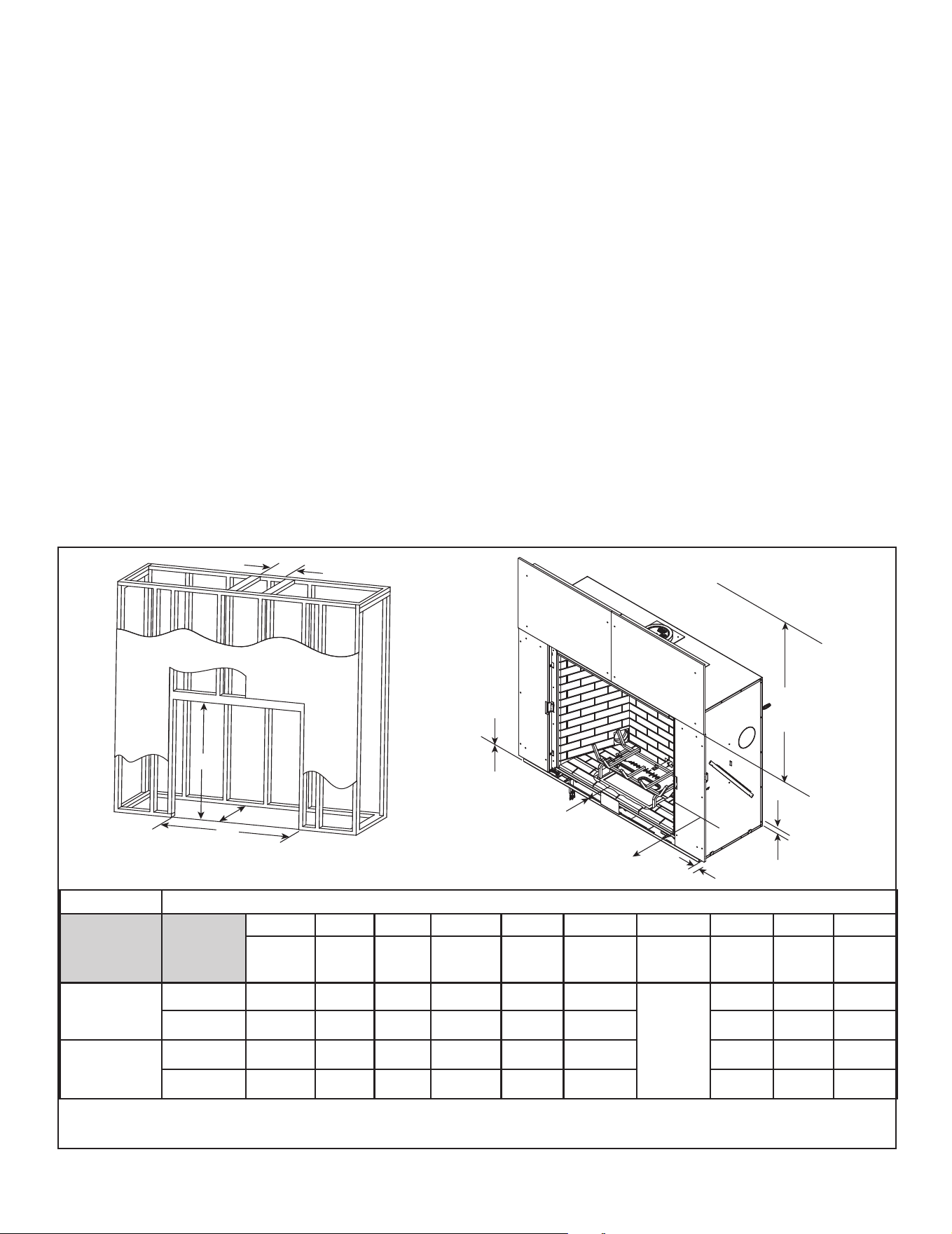
Non-Combustible Zone
Figure 3.5 Non-Combustible Zone
NO COMBUSTIBLES
IN HATCHED AREA
1/2 IN. BUILDING MATERIAL
(MAY BE COMBUSTIBLE)
FACTORY-SUPPLIED
1/2 IN.
NON-COMBUSTIBLE
BOARD
PIPE IS FOR VISUAL
REFERENCE ONLY
1 IN.
= COMBUSTIBLES
NOT ALLOWED
39 IN.
2 X 4 OR GREATER
FRAMING MATERIAL
NOTE:
2 X 4 HEADER
CONFIGURATION
2 X 4 ONLY IN
GRAY AREA
1/2 IN.
13
Majestic MARQ36IN-B, MARQ42IN-B Installation Manual • 2614-980 Rev. P • 5/22
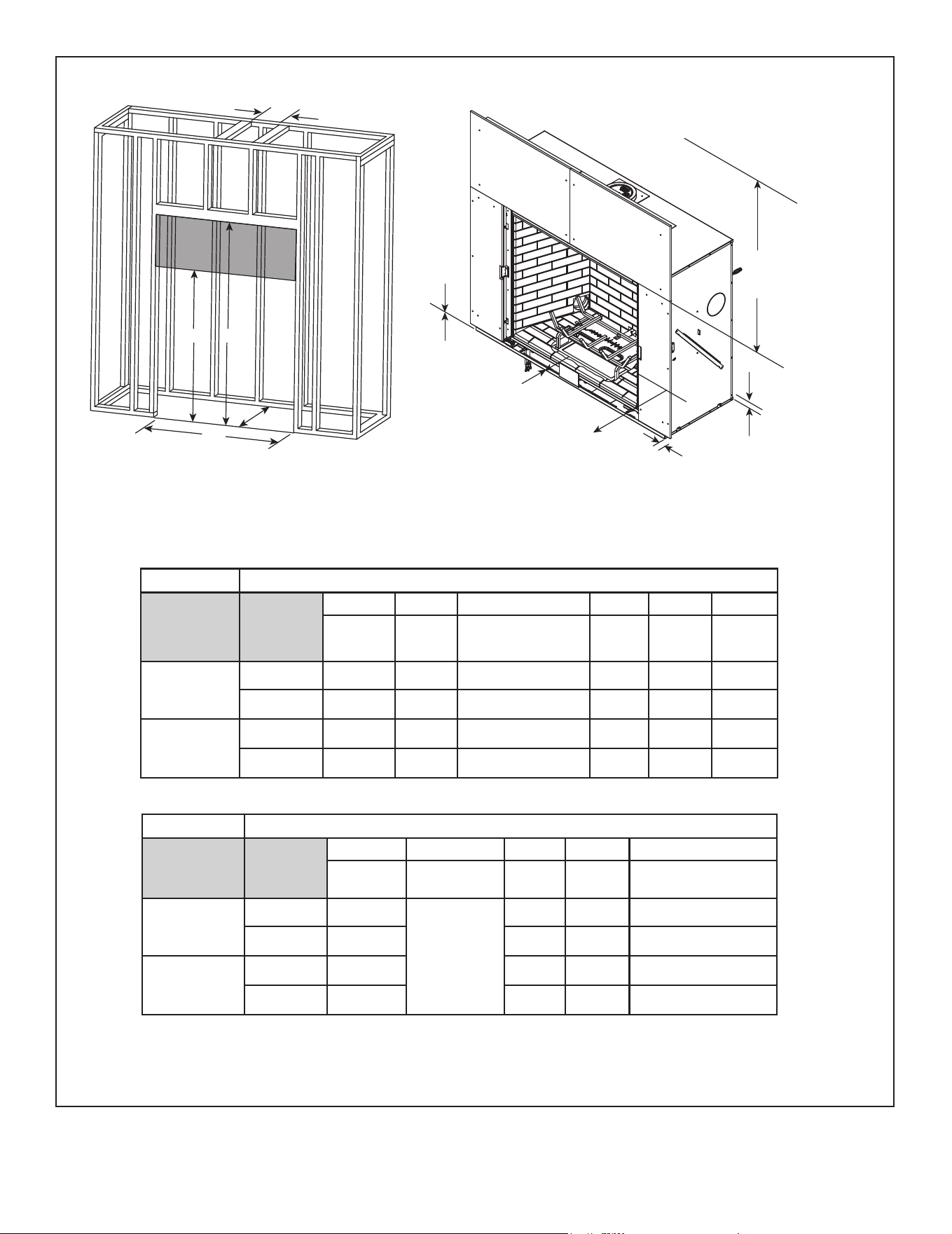
* MINIMUM FRAMING DIMENSIONS USING 2 X 4 CONSTRUCTION
A B C D E F G** H I J
Rough
Opening
(Vent Pipe)
Rough
Opening
(Height)
Rough
Opening
(Depth)
Rough
Opening
(Width)
Clearance
to Ceiling
Combustible
Floor
Combustible
Flooring
Behind
Appliance
Sides of
Appliance
Front of
Appliance
MARQ36IN-B
Inches 10 56 24 59-1/2 52 0
See
Section
3.D.
1 1 36
Millimeters 254 1422 610 1511 1321 0 25 25 914
MARQ42IN-B
Inches 10 61 24 65-9/16 52 0 1 1 36
Millimeters 254 1549 610 1665 1321 0 25 25 914
C. Constructing the Appliance Chase
A chase is a vertical box-like structure built to enclose the
gas appliance and/or its vent system. In cooler climates
the vent should be enclosed inside the chase.
NOTICE: Treatment of ceiling restops and wall shield
restops and construction of the chase may vary with the
type of building. These instructions are not substitutes
for the requirements of local building codes. Therefore,
you MUST check local building codes to determine the
requirements to these steps.
NOTICE: When installing a sprinkler head in a replace
chase, it is recommended to use a sprinkler head with a
sprinkler activation temperature classied as Extra High.
Keep sprinkler head away from vent and chimney.
Chases should be constructed in the manner of all out-
side walls of the home to prevent cold air drafting prob-
lems. The chase should not break the outside building
envelope in any manner.
Walls, ceiling, base plate and cantilever oor of the chase
should be insulated. Vapor and air inltration barriers
should be installed in the chase as per regional codes for
the rest of the home. Additionally, in regions where cold
air inltration may be an issue, the inside surfaces may be
sheetrocked and taped for maximum air tightness.
Figure 3.6 Clearances to Combustibles (2 X 4 Construction)
NOTICE: Install appliance on hard metal or wood surfaces
extending full width and depth. DO NOT install directly
on carpeting, vinyl, tile or any combustible material other
than wood.
WARNING! Risk of Fire! Maintain specied air space
clearances to appliance and vent pipe:
• Insulation and other materials must be secured to prevent
accidental contact.
• The chase must be properly blocked to prevent blown
insulation or other combustibles from entering and
making contact with replace or chimney.
• Failure to maintain airspace may cause overheating and
a re.
* Adjust framing dimensions for interior sheathing (such as sheetrock)
F
H
G
I
J
E
(FROM APPLIANCE
OPENING TO CEILING)
To further prevent drafts, the wall shield and ceiling re-
stops should be caulked with caulk with a minimum of
300 ºF continuous exposure rating to seal gaps. Gas
line holes and other openings should be caulked with
caulk with a minimum of 300 ºF continuous exposure rating
or stuffed with unfaced insulation. If the appliance is being
installed on a cement surface, a layer of plywood may be
placed underneath to prevent conducting cold up into the
room.
NOTE: 2 X 4 Header positioned vertically. See also Figure 3.5.
C
B
D
A
** For installations with vinyl ooring, see Section 3.E.
Majestic MARQ36IN-B, MARQ42IN-B Installation Manual • 2614-980 Rev. P • 5/2214
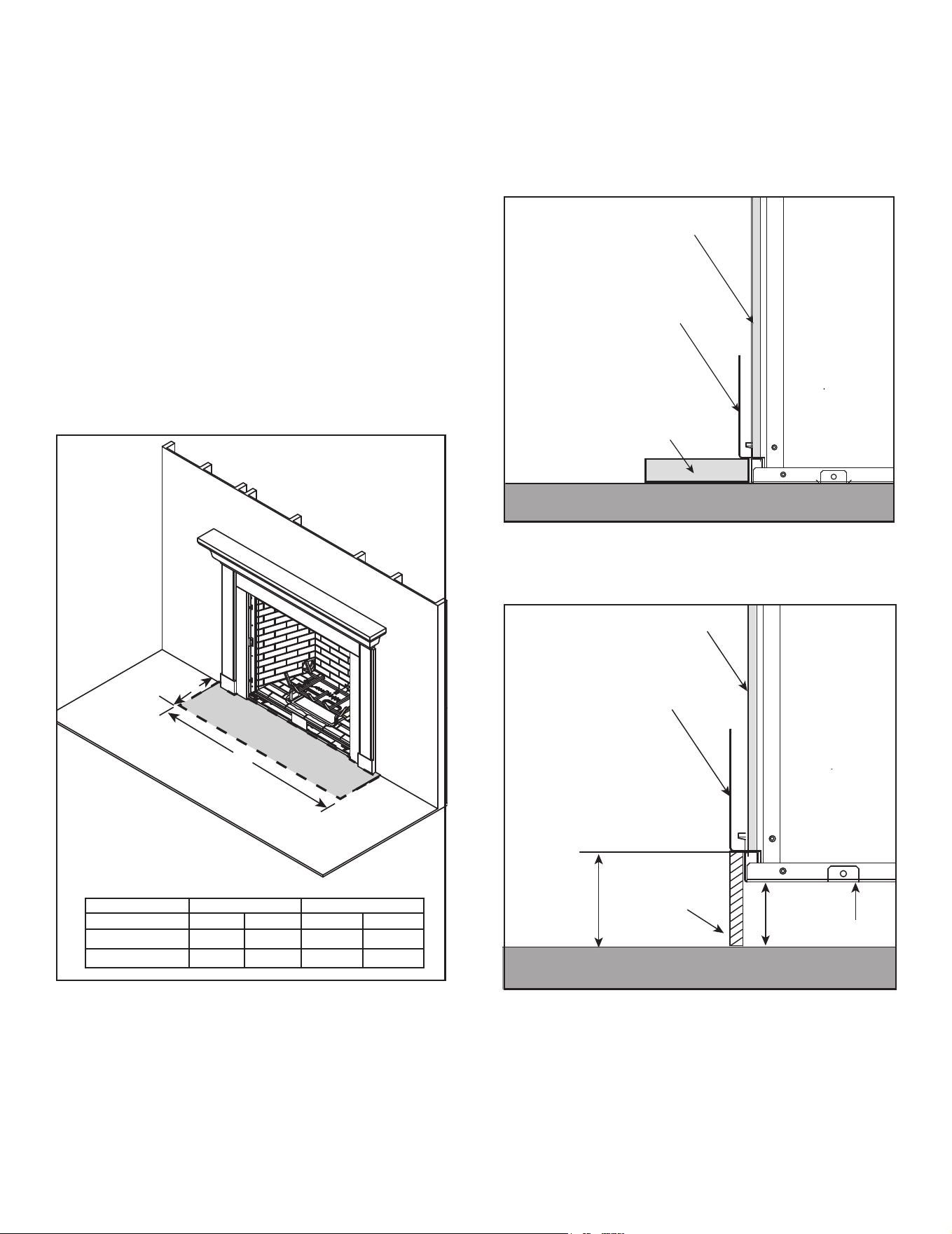
Figure 3.7 Clearances to Combustibles (2 x 6 Construction)
* Adjust framing dimensions for interior sheathing (such as sheetrock).
** 2 x 4 material must be framed down from 2 x 6 rough opening height B’ to rough opening height B.
F
H
G
I
J
E
(FROM APPLIANCE
OPENING TO CEILING)
* MINIMUM FRAMING DIMENSIONS USING 2 X 6 CONSTRUCTION
A B B’ C D E
Rough
Opening
(Vent Pipe)
Rough
Opening
(Height)
**Rough Opening Height
Rough
Opening
(Depth)
Rough
Opening
(Width)
Clearance
to Ceiling
MARQ36IN-B
Inches 10 56 80-3/8 24 59-1/2 52
Millimeters 254 1422 2042 610 1511 1321
MARQ42IN-B
Inches 10 61 85-3/8 24 65-9/16 52
Millimeters 254 1549 2169 610 1665 1321
NOTE: 2 X 4 Header positioned vertically. See also Figure 3.5.
* MINIMUM FRAMING DIMENSIONS USING 2 X 6 CONSTRUCTION
F G*** H I J
Combustible
Floor
Combustible
Flooring
Behind
Appliance
Sides of
Appliance
Front of
Appliance
MARQ36IN-B
Inches 0
See Section
3.D.
1 1 36
Millimeters 0 25 25 914
MARQ42IN-B
Inches 0 1 1 36
Millimeters 0 25 25 914
A
B
D
C
B’
2 X 6 OR GREATER NOT ALLOWED IN SHADED AREA
*** For installations with vinyl ooring, see Section 3.E.
15
Majestic MARQ36IN-B, MARQ42IN-B Installation Manual • 2614-980 Rev. P • 5/22
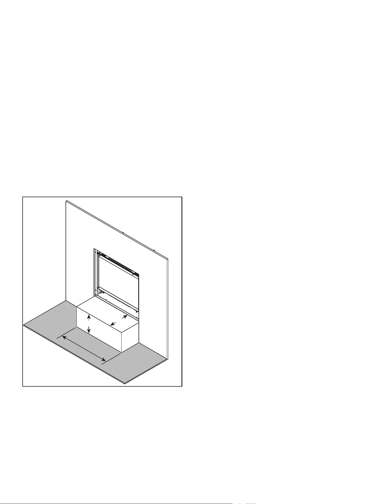
NON-COMBUSTIBLE
BOARD
HEARTH CLEARANCE
BRACKET
NON-COMBUSTIBLE
HEARTH EXTENSION
1 IN. THICK MAX.
WOOD OR OTHER COMBUSTIBLE
FLOOR OR PLATFORM
D. Hearth Extension
WARNING! Risk of Fire! Non-combustible hearth exten-
sion may be required when appliance is installed on com-
bustible surface.
• Hearth extension must be non-combustible and
serves to protect combustible oors in front of appli-
ance. See Figure 3.8 and Figure 3.9.
• The base of the replace may sit on a combustible
surface. See Figure 3.9. The area in front of the
appliance must be protected by a non-combustible
hearth extension, unless the appliance is raised a
minimum of three inches above the combustible oor
or hearth. See Figure 3.9 and Figure 3.10.
• If a hearth greater than one inch in thickness is de-
sired, the appliance must be raised by the equivalent
height to ensure that the hearth extension does not
interfere with the installation of the glass assembly
required for replace operation. See Figure 3.9.
Figure 3.8 Non-Combustible Hearth Extension Dimensions
A
B
NON-COMBUSTIBLE
MODEL A B
in. mm in. mm
MARQ36IN-B 12 305 57-1/4 1454
MARQ42IN-B 12 305 63-5/16 1608
Figure 3.9 Appliance Installed on Combustible Surface
Non-Combustible Hearth Extension REQUIRED.
NOTICE: DO NOT install a hearth that is greater than
one inch thick. Hearth will interfere with installation of
glass assembly. Total hearth height must not exceed one
inch from bottom of appliance when appliance is installed
directly on oor (including mortar, backer material, etc.).
NON-COMBUSTIBLE
BOARD
HEARTH CLEARANCE
BRACKET
WOOD OR OTHER COMBUSTIBLE
FLOOR OR PLATFORM
4 IN.
3 IN. MIN.
BOTTOM OF
FIREPLACE
1/2 IN. MAX.
THICKNESS
COMBUSTIBLE
BUILDING
MATERIAL
Figure 3.10 Appliance Raised a Minimum of 3 Inches Above
Combustible Surface. Non-Combustible Hearth Ex-
tension NOT REQUIRED.
Majestic MARQ36IN-B, MARQ42IN-B Installation Manual • 2614-980 Rev. P • 5/2216
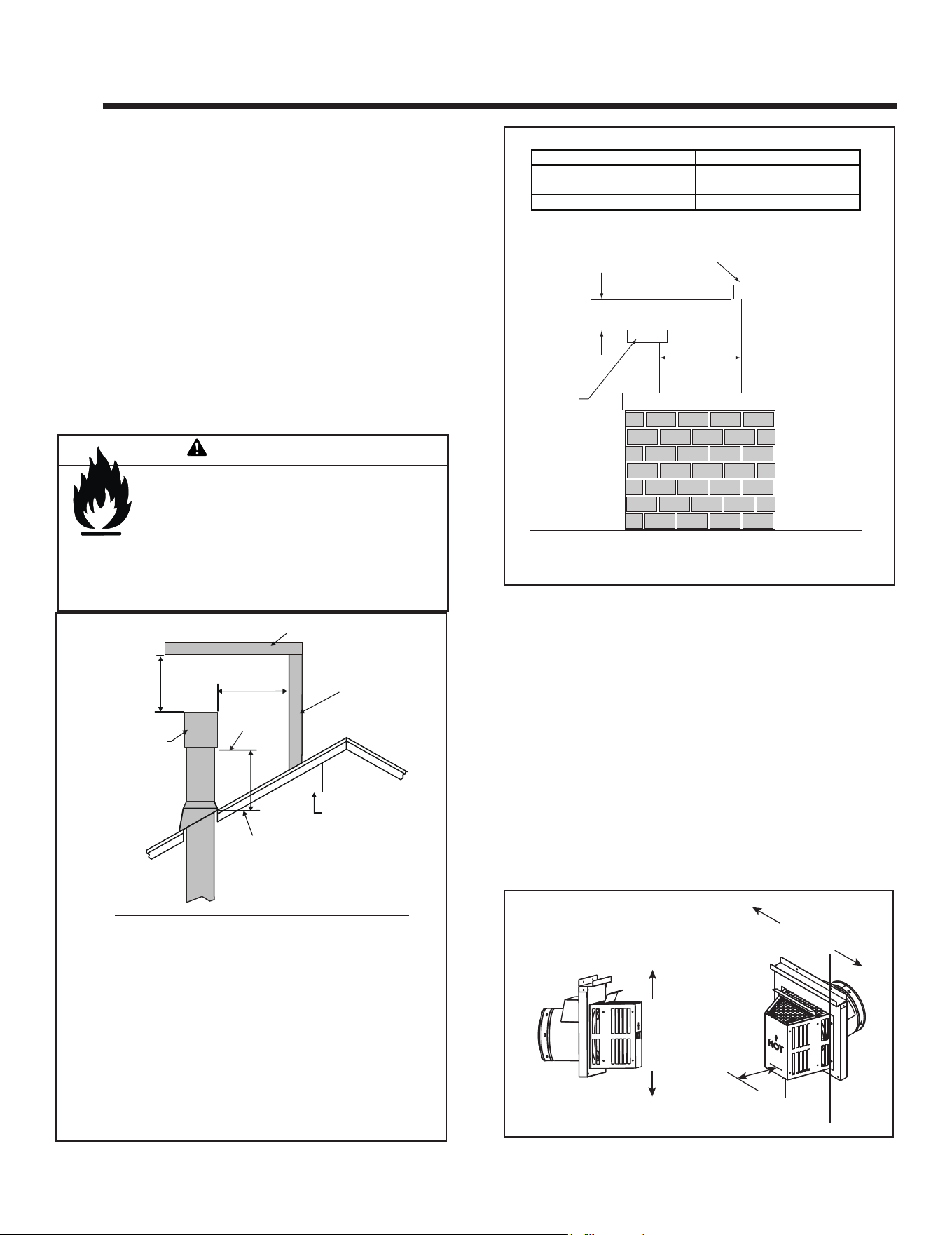
E. Floor Protection
12 IN. MIN.
APPLIANCE WIDTH MIN.
12 IN. MIN.
VINYL
Figure 3.11 Vinyl Flooring Recommendations
Vinyl ooring is sensitive to heat. To avoid damage to
the vinyl ooring, a 12 inch minimum x 12 inch mini-
mum hearth is recommended when using vinyl ooring
up to the wall. See Figure 3.11. If no hearth is used,
it is recommended to provide a minimum of 36 inches
of clearance in front of the appliance to the vinyl oor-
ing OR the bottom of the appliance should be raised a
minimum of 24 inches off of the oor to allow the vinyl
ooring to be installed up to the wall.
NOTICE: Clearances that do not meet the minimum
guidelines could result in damage or buckling to the vinyl
ooring and is done at the installer’s risk.
Hearth and Home Technologies does not recommend
adhesive based vinyl ooring products due to thermal ex-
pansion during operation. Floating style ooring can be
used, but it will reach temperatures up to 110 °F (based
on ambient temperature of 70 °F). Consult the manufac-
turer’s ooring specications to ensure compatibility.
Vinyl Flooring
17
Majestic MARQ36IN-B, MARQ42IN-B Installation Manual • 2614-980 Rev. P • 5/22
HORIZONTAL
OVERHANG
VERTICAL
WALL
GAS DIRECT VENT
TERMINATION CAP
12
X
ROOF PITCH
IS X/ 12
LOWEST
DISCHARGE
OPENING
2 FT.
MIN.
20 INCHES MIN.
H (MIN.) - MINIMUM HEIGHT FROM ROOF
TO LOWEST DISCHARGE OPENING
4 4
Termination Location and Vent Information
B. Vent Termination Minimum Clearances
Roof Pitch H (Min.) Ft
Flat to 6/12...........................................................1.0*
Over 6/12 to 7/12 .................................................1.25*
Over 7/12 to 8/12 .................................................1.5*
Over 8/12 to 9/12 .................................................2.0*
Over 9/12 to 10/12 ...............................................2.5*
Over 10/12 to 11/12 .............................................3.25
Over 11/12 to 12/12 .............................................4.0
Over 12/12 to 14/12 .............................................5.0
Over 14/12 to 16/12 .............................................6.0
Over 16/12 to 18/12 .............................................7.0
Over 18/12 to 20/12 .............................................7.5
Over 20/12 to 21/12 .............................................8.0
Figure 4.1 Minimum Height From Roof to Lowest Discharge
Opening
Fire Risk.
Maintain vent clearance to combustibles as
specied.
• DO NOT pack air space with insulation or other
materials.
Failure to keep insulation or other materials away
from vent pipe could cause overheating and re.
WARNING
Figure 4.2 Staggered Termination Caps
* H minimum may vary depending on regional snowfall.
Refer to local codes.
A. Approved Pipe
WARNING! Risk of Fire, Delayed Ignition or Asphyxi-
ation. This appliance requires a separate vent. DO NOT
vent to a pipe serving any other appliance.
This appliance is only approved for use with Hearth & Home
Technologies DVP or SLP venting systems. Refer to Sec-
tion 12.A for vent component information and dimensions.
Only use listed decorative termination caps/shrouds with
Hearth & Home Technologies approved venting systems.
DO NOT mix pipe, ttings or joining methods from different
manufacturers.
The pipe is tested to be run inside an enclosed wall. There
is no requirement for inspection openings at each joint with-
in the wall.
CAUTION! Risk of Burns! Termination caps are HOT,
consider proximity to doors, trafc areas or where people
may pass or gather (sidewalk, deck, patio, etc.). Listed
cap shields available. Contact your dealer.
• Local codes or regulations may require different
clearances.
• Hearth & Home Technologies assumes no responsibility
for the improper performance of the appliance when the
venting system does not meet these requirements.
• Vinyl protection kits are suggested for use with vinyl siding.
• Measure horizontal and vertical termination cap clearances
as noted in Figure 4.3.
Figure 4.3
CLEARANCE
= 6 IN.
H
V
V
H=Measure Horizontal Distances from H
V=Measure Vertical Distances from V
H
Wood or Fuel Oil
Termination Cap
B
*Gas
Termination
Cap
A
*
If two gas terminations are present, they may be level (B = 0 inches)
provided A is a minimum of 6 inches.
A B
6 in. (minimum) up to 20 in.
152 mm/508 mm
18 in. minimum
457 mm
20 in. and over 0 in. minimum
Majestic MARQ36IN-B, MARQ42IN-B Installation Manual • 2614-980 Rev. P • 5/2218
C
J
B
D
B
F
B
A
E
V
V
V
V
V
V
M
H or i
V
G
X
V
H
A
V
V
H
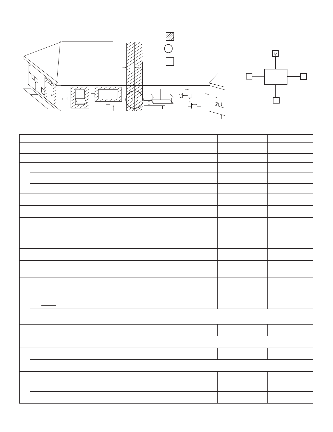
Figure 4.4 Minimum Clearances for Termination
X
= AIR SUPPLY INLET
V
= VENT TERMINAL
= AREA WHERE TERMINAL IS NOT PERMITTED
Electrical
Service
V
K
V
K
V
L
C
V
C. Vent Terminal Clearances
U.S.A. CANADA
A Clearance above grade,veranda, porch, deck, balcony or roof. 12 in. (305 mm) 12 in. (305 mm)
B Clearance to window or door that may be opened, or to permanently closed window 12 in. (305 mm) 112 in. (305 mm)
C
Clearance below unventilated soft 18 in. (457 mm) 18 in. (457 mm)
Clearance below ventilated soft 18 in. (457 mm) 18 in. (457 mm)
Clearance below any vinyl softs and electrical service 42 in. (1067 mm) 42 in. (1067 mm)
D Clearance to outside corner 6 in. (152 mm) 6 in. (152 mm)
E Clearance to inside corner 6 in. (152 mm) 6 in. (152 mm)
F Clearance to each side of center line extended above gas meter/regulator assembly
Clearance in accor-
dance with local instal-
lation codes and the
requirements of the gas
supplier.
3 ft (914 mm) within
a height 15 ft (4.5
m) above the meter/
regulator assembly
G Clearance to gas service regulator vent outlet 3 ft (914 mm) 3 ft (914 mm)
H
Clearance to non-mechanical air supply inlet to building or the combustion air inlet to
any other appliance termination (mechanical or non-mechanical)
12 in. (305 mm) 12 in. (305 mm)
I
Clearance to a mechanical (powered) air supply inlet
***(All mechanical air intakes within 10 feet of a horizontal termination cap must be
a minimum of 3 feet below termination.)
3 ft (914 mm)*** 6 ft (1.8 m)
J
On public property: clearance above paved sidewalk or a paved driveway. 7 ft (2.1 m) 7 ft (2.1 m)**
**(A vent shall not terminate directly above a sidewalk or paved driveway which is located between two single family dwellings and
serves both dwellings.)
K
Clearance from sides of electrical service 6 in. (152 mm) 6 in. (152 mm)
Location of the vent termination must not interfere with access to the electrical service.
L
Clearance above electrical service 12 in. (305 mm) 12 in. (305 mm)
Location of the vent termination must not interfere with access to the electrical service.
M
Clearance under veranda, porch, deck, balcony or overhang
*(Permitted only if veranda, porch, deck, or balcony is fully open on a minimum of
two sides beneath the oor.)
24 in. (610 mm)* 24 in. (610 mm)*
Vinyl or composite overhang 42 in. (1067 mm) 42 in. (1067 mm)
U.S.A. Installations: In accordance with the current ANSI Z223.1/NFPA 54, National Fuel Gas Code.
Canadian Installations: In accordance with the current CSA B149.1, Natural Gas and Propane Installation Code.
19
Majestic MARQ36IN-B, MARQ42IN-B Installation Manual • 2614-980 Rev. P • 5/22
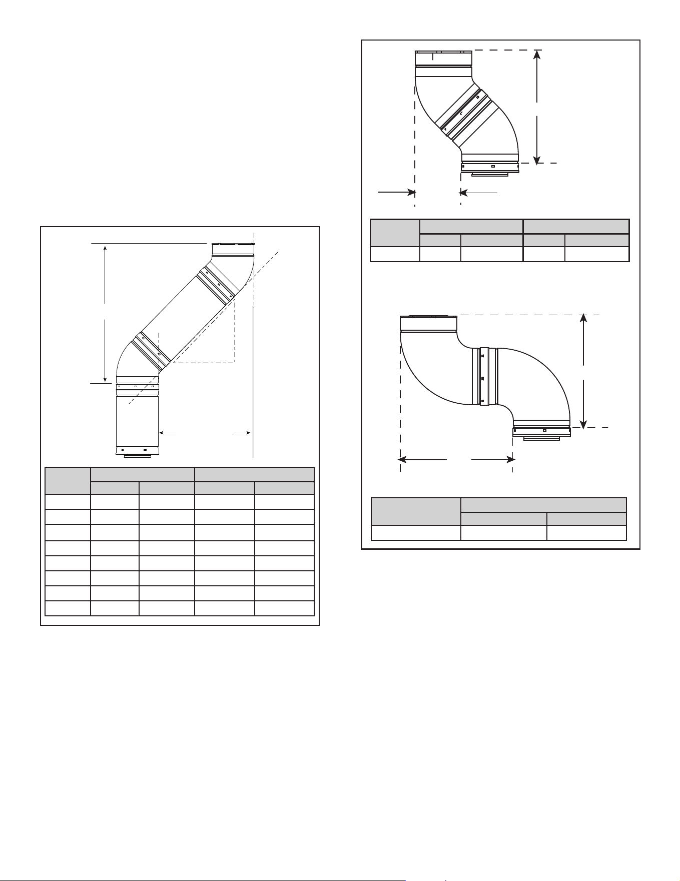
E. Use of Elbows
Diagonal runs have both vertical and horizontal vent
aspects when calculating the effects. Use the rise for the
vertical aspect and the run for the horizontal aspect. See
Figure 4.5.
Two 45º elbows may be used in place of one 90º elbow.
On 45º runs, one foot of diagonal is equal to 8-1/2 in. (216
mm) horizontal run and 8-1/2 in. (216 mm) vertical run. A
length of straight pipe is allowed between two 45º elbows.
See Figure 4.5.
Figure 4.6 shows the vertical and horizontal offsets for
DVP elbows.
Figure 4.5
HORIZONTAL
VERTICAL
RUN
RISE
EFFECTIVE
LENGTH
DVP
Pipe
Effective Length Rise/Run
Inches Millimeters Inches Millimeters
DVP4 4 102 2-3/4 70
DVP6 6 152 4-1/4 108
DVP12 12 305 8-1/2 216
DVP24 24 610 17 432
DVP36 36 914 25-1/2 648
DVP48 48 1219 34 864
DVP6A 3 to 6 76 to 152
2-1/8-4-1/4 54-108
DVP12A 3 to 12 76 to 305
2-1/8-8-1/2 54-216
Y
X
X
X
Vent Type
X
Inches Millimeters
DVP 16-1/4 413
Figure 4.6 Vertical and Horizontal Offset for DVP Elbows
Vent
Type
X Y
Inches Millimeters Inches Millimeters
DVP 6-5/8 168 16-1/2 419
Majestic MARQ36IN-B, MARQ42IN-B Installation Manual • 2614-980 Rev. P • 5/2220
F. Measuring Standards
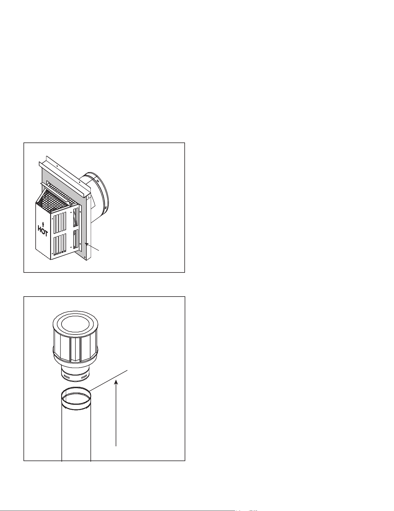
Vertical and horizontal measurements listed in the vent
diagrams were made using the following standards:
• Pipe measurements are shown using the effective length
of pipe. See Section 12.A (Figure 12.1) for information
on effective length of pipe components.
• Horizontal terminations are measured to the outside
mounting surface (ange of termination cap) (see Figure
4.7).
• Vertical terminations are measured to top of last section
of pipe. See Figure 4.8.
• Horizontal pipe installed level with no rise.
MEASURE TO SHADED SURFACE
(OUTSIDE MOUNTING SURFACE)
Figure 4.7 Measure to Outside Mounting Surface
Figure 4.8 Measure to Top of Last Section of Pipe
21
Majestic MARQ36IN-B, MARQ42IN-B Installation Manual • 2614-980 Rev. P • 5/22
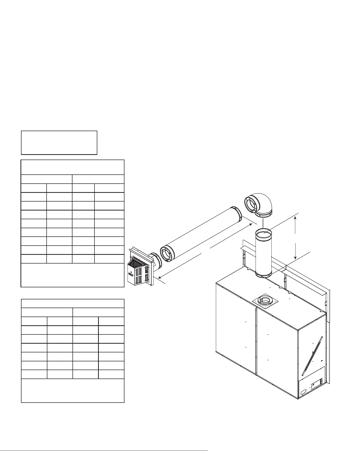
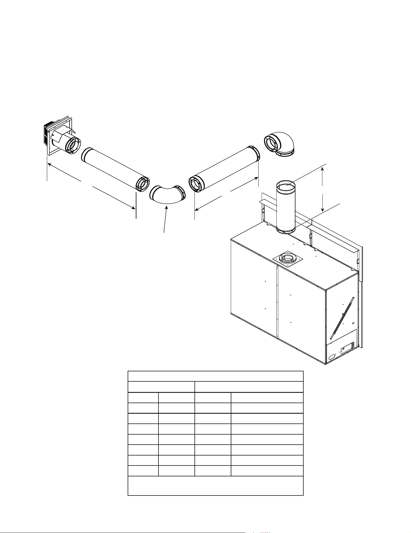
G. Vent Diagrams
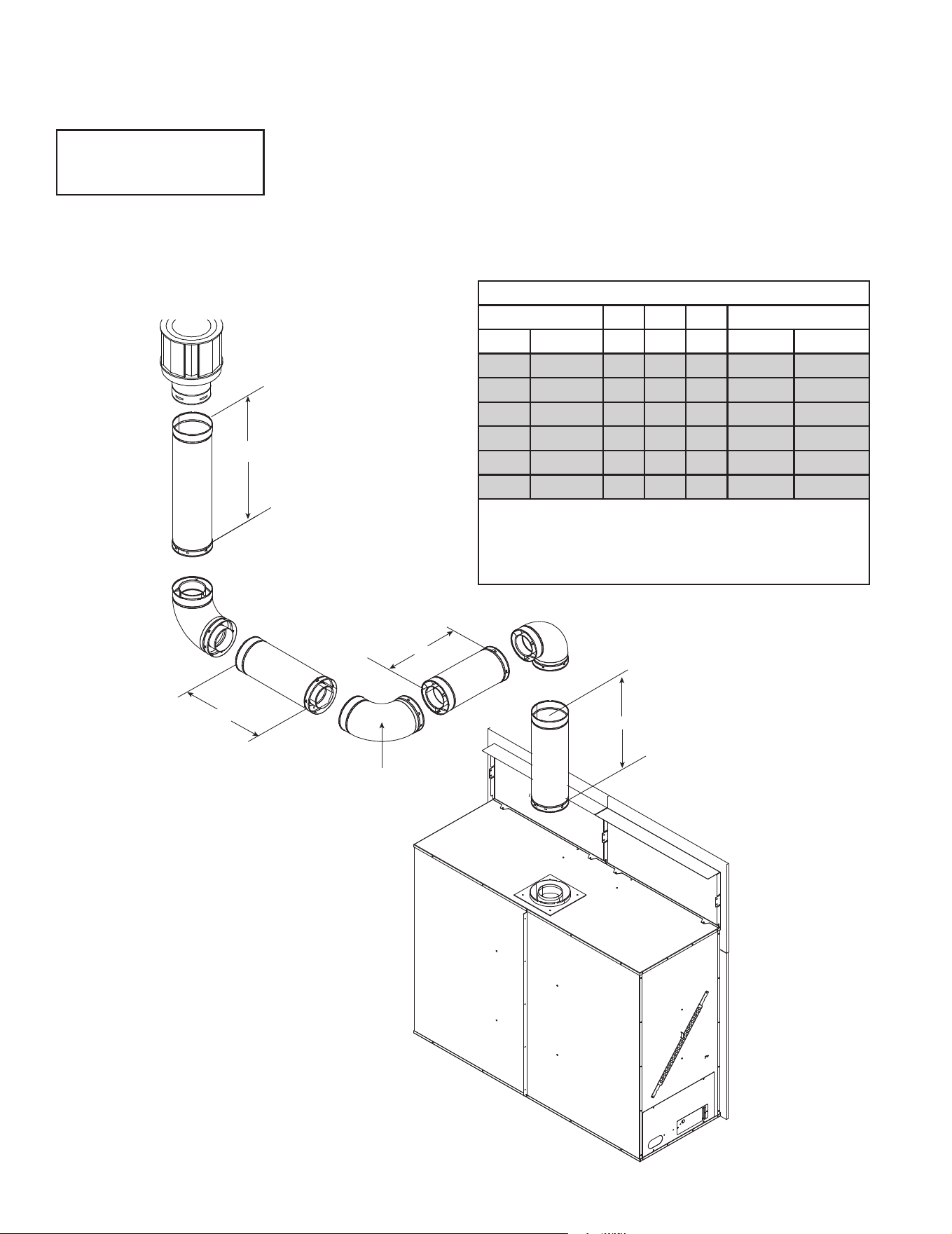
WARNING! Risk of Fire. This appliance requires a minimum of 24 inches of vertical venting before attaching any elbow to
the appliance. DO NOT attach elbow directly to the appliance.
General Rules:
• This appliance is approved for use with Hearth & Home Technologies DVP venting systems ONLY.
• When penetrating a combustible wall, a wall shield restop must be installed.
• When penetrating a combustible ceiling, a ceiling restop must be installed.
• This appliance requires a minimum of 24 inches of vertical pipe attached directly to the appliance starting collar before
attaching a 90 degree or 45 degree elbow.
• Horizontal termination cap should have a 1/4 inch downward slant to allow any moisture in cap to be released.
H
1
V
1
Top Vent - Horizontal Termination
Figure 4.9
One Elbow
MARQ36IN-B (NG/Propane),
MARQ42IN-B (NG)
V
1
Minimum H
1
Maximum
2 ft 610 mm 7 in* 178 mm
2.5 ft 762 mm 17 in 432 mm
3 ft 914 mm 2 ft 610 mm
4 ft 1.2 m 4 ft 1.2 m
5 ft 1.5 m 9 ft 2.7 m
6 ft 1.8 m 12 ft 3.7 m
7 ft 2.1 m 14 ft 4.3 m
10 ft 3.0 m 20 ft 6.1 m
20 ft 6.1 m 40 ft 12.2 m
After V
1
= 6 ft then H
1
= 2 x V ft Maximum
V
1
+ H
1
= 60 ft Maximum
*when used with approved termination caps
Note: Flue restrictor is permit-
ted ONLY on 30 ft. minimum
vertical runs with no elbows.
WARNING! Risk of Fire!
• MARQ36IN-B (NG/Propane) and MARQ42IN-B (NG) models require
a minimum of 24 inches of vertical venting before attaching any
elbow to the appliance.
• MARQ42IN-B (Propane) model requires a minimum of 36 inches of
vertical venting before attaching any elbow to the appliance.
DO NOT attach elbow directly to the appliance.
MARQ42IN-B (Propane)
V
1
Minimum H
1
Maximum
3 ft 914 mm 10 in. 254 mm
4 ft 1.2 m 4 ft 1.2 m
5 ft 1.5 m 9 ft 2.7 m
6 ft 1.8 m 12 ft 3.7 m
7 ft 2.1 m 14 ft 4.3 m
10 ft 3.0 m 20 ft 6.1 m
20 ft 6.1 m 40 ft 12.2 m
After V
1
= 6 ft then H
1
= 2 x V ft Maximum
V
1
+ H
1
= 60 ft Maximum
*when used with approved termination caps
Majestic MARQ36IN-B, MARQ42IN-B Installation Manual • 2614-980 Rev. P • 5/2222
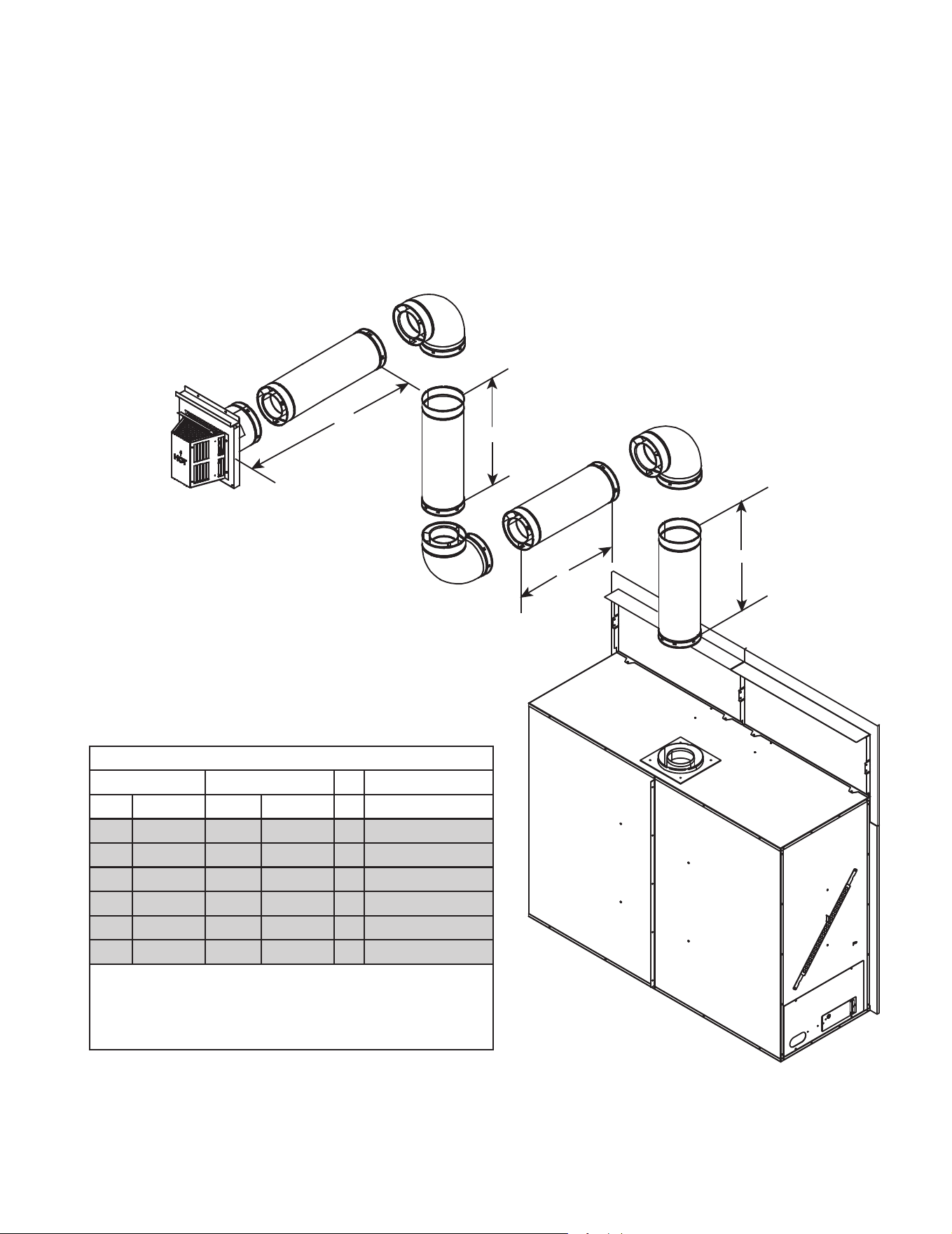
Figure 4.10
H
2
H
1
INSTALLED
HORIZONTALLY
V
1
Two Elbows
MARQ36IN-B (NG/Propane), MARQ42IN-B (NG/Propane)
V
1
Minimum
H
1
+ H
2
3 ft 914 mm 18 in 457 mm
4 ft 1.2 m 3 ft 914 mm
5 ft 1.5 m 7 ft 2.1 m
6 ft 1.8 m 10 ft 3.0 m
7 ft 2.1 m 14 ft 4.3 m
8 ft 2.4 m 16 ft 4.9 m
9 ft 2.7 m 18 ft 5.5 m
10 ft 3.0 m 20 ft 6.1 m
V
1
+ H
1
+ H
2
= 60 ft Maximum
H
1
+ H
2
= 20 ft Maximum
WARNING! Risk of Fire!
• MARQ36IN-B (NG/Propane) MARQ42IN-B (NG/Propane), model
requires a minimum of 36 inches of vertical venting before attaching
any elbow to the appliance.
DO NOT attach elbow directly to the appliance.
23
Majestic MARQ36IN-B, MARQ42IN-B Installation Manual • 2614-980 Rev. P • 5/22
H
2
H
1
V
2
V
1
Figure 4.11
Top Vent - Horizontal Termination - (continued)
Three Elbows
MARQ36IN-B (NG/PROPANE), MARQ42IN-B (NG)
V
1
H
1
V
2
H
2
2 ft 610 mm 7 in 178 mm * H
2
Max = 2 X V
2
3 ft 914 mm 2 ft 610 mm * H
2
Max = 2 X V
2
4 ft 1.2 m 4 ft 1.2 m * H
2
Max = 2 X V
2
5 ft 1.5 m 9 ft 2.7 m * H
2
Max = 2 X V
2
6 ft 1.8 m 12 ft 3.7 m * H
2
Max = 2 X V
2
7 ft 2.1 m 14 ft 4.3 m * H
2
Max = 2 X V
2
10 ft 3.0 m 20 ft 6.1 m * H
2
Max = 2 X V
2
Shaded area of chart is for MARQ42IN-B (Propane)
V
1
+ H
1
must be adhered to.
* V
2
has no specic restrictions EXCEPT,
H
t max
= 2 x V
t
and V
total
+ H
total
cannot exceed 60 ft Maximum
WARNING! Risk of Fire!
•• MARQ36IN-B (NG/Propane) and MARQ42IN-B (NG) models require
a minimum of 24 inches of vertical venting before attaching any elbow
to the appliance.
• MARQ42IN-B (Propane) model requires a minimum of 36 inches of
vertical venting before attaching any elbow to the appliance.
DO NOT attach elbow directly to the appliance.
Majestic MARQ36IN-B, MARQ42IN-B Installation Manual • 2614-980 Rev. P • 5/2224
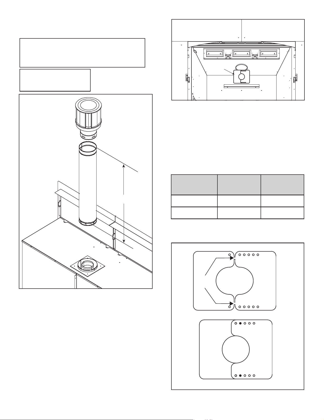
Top Vent - Vertical Termination
No Elbow
V
1
= 50 ft. Max. (15.2 m)
V
1
= 2 ft. Min. (610 mm)
Note: Flue restrictor is permit-
ted ONLY on 30 ft. minimum
vertical runs with no elbows.
V
1
Figure 4.12
NOTE: Exhaust Restrictor ships
in manual bag assembly
Figure 4.13 Exhaust Restrictor Installation
Exhaust Restrictor Instructions
1. Remove the top piece of refractory, if already installed.
2. Break the exhaust restrictor into two pieces. Do this
by bending the part back and forth until it breaks.
See Figure 4.14.
3. Orientate and align the two pieces of the exhaust
restrictor as shown in Figure 4.14.
4. Match the amount of vertical you have in the system
with the chart to nd the appropriate position to set the
exhaust restrictor. See Table 4.1.
5. Center the two exhaust restrictor pieces on the vent at
the setting selected in step 3 and secure in place by
using two self-tapping screws. See Figure 4.13.
6. Reinstall the top refractory.
Vertical Pipe MARQ36IN-B MARQ42IN-B
Up to 30 ft.
No
Restrictor
No
Restrictor
31-50 ft. 2-2 2-2
Table 4.1.
Figure 4.14 Exhaust Restrictor Installation
BREAK
HERE
EXHAUST RESTRICTOR SET TO 2-2
1
1
1
1
2
2
3
3
4
4
5
5
5
5
2
3
4
2
3
4
Exhaust restrictors are recommended for these vertically
terminated products which have excessive draft. Ex-
haust restrictors will compensate for high draft, and re-
store visual ame height. If the vent conguration has a
total vertical of 31-50 feet, an exhaust restrictor may be
needed. The exhaust restrictor can be located in the ap-
pliance manual bag.
EXHAUST
RESTRICTOR
25
Majestic MARQ36IN-B, MARQ42IN-B Installation Manual • 2614-980 Rev. P • 5/22
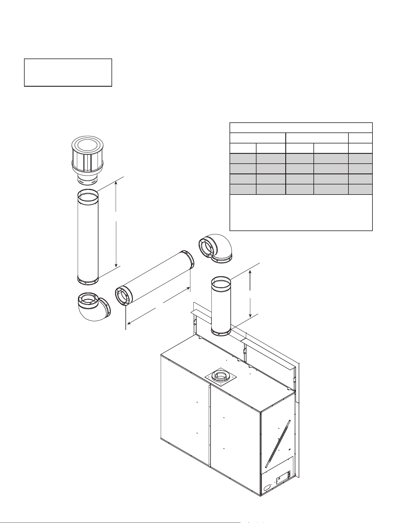
MARQ36IN-B (NG/Propane), MARQ42IN-B (NG)
V
1
H
1
V
2
2 ft 610 mm 1 ft 305 mm *
3 ft 914 mm 3 ft 914 mm *
4 ft 1.2 m 4 ft 1.2 m *
5 ft 1.5 m 9 ft 2.7 m *
6 ft 1.8 m 12 ft 3.7 m *
Shaded area of chart is for MARQ42IN-B (Propane)
*No specic restrictions on this value EXCEPT
V
1
+ V
2
+ H
1
= 50 ft (15.2 m) Max.
After V
1
= 6 ft, then H
1
Max.= V
1
x 2
Note: Flue restrictor is permit-
ted ONLY on 30 ft. minimum
vertical runs with no elbows.
H
1
V
1
V
2
Two Elbows
Top Vent - Vertical Termination - (continued)
Figure 4.15
WARNING! Risk of Fire!
•• MARQ36IN-B (NG/Propane) and MARQ42IN-B (NG) models require
a minimum of 24 inches of vertical venting before attaching any elbow
to the appliance.
• MARQ42IN-B (Propane) model requires a minimum of 36 inches of
vertical venting before attaching any elbow to the appliance.
DO NOT attach elbow directly to the appliance.
Majestic MARQ36IN-B, MARQ42IN-B Installation Manual • 2614-980 Rev. P • 5/2226
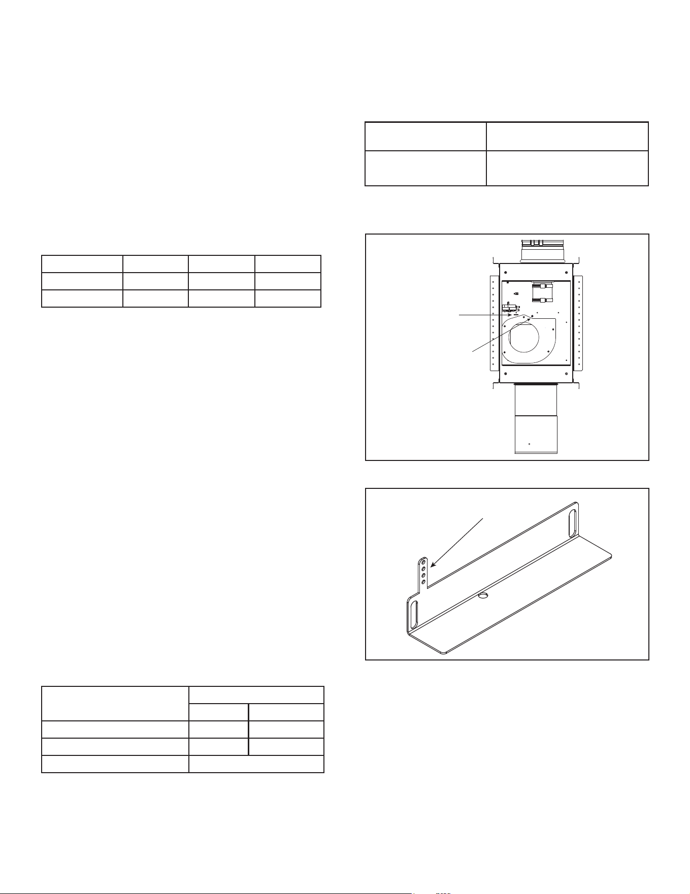
Three Elbows
MARQ36IN-B (NG/PROPANE), MARQ42IN-B (NG)
V
1
H
1
H
2
V
2
H
t
Max.
2 ft 610 mm * * ** 7 in 178 mm
3 ft 914 mm * * ** 2 ft 610 mm
4 ft 1.2 m * * ** 4 ft 1.2 m
5 ft 1.5 m * * ** 8 ft 2.4 m
6 ft 1.8 m * * ** 12 ft 3.7 m
7 ft 2.1 m * * ** 14 ft 4.3 m
10 ft 3.0 m * * ** 20 ft 6.1 m
Shaded area of chart is for MARQ42IN-B (Propane)
*H
1
and H
2
has no specic restrictions EXCEPT,
after V
1
= 6 ft, then H
TOTAL
Max = 2 x V
1
**V
TOTAL +
H
TOTAL
= 50 ft (15.2 m) Max.
Note: Flue restrictor is permit-
ted ONLY on 30 ft. minimum
vertical runs with no elbows.
INSTALLED
HORIZONTALLY
H
1
H
2
V
1
V
2
Top Vent - Vertical Termination - (continued)
Figure 4.16
WARNING! Risk of Fire!
•• MARQ36IN-B (NG/Propane) and MARQ42IN-B (NG) models require
a minimum of 24 inches of vertical venting before attaching any elbow
to the appliance.
• MARQ42IN-B (Propane) model requires a minimum of 36 inches of
vertical venting before attaching any elbow to the appliance.
DO NOT attach elbow directly to the appliance.
27
Majestic MARQ36IN-B, MARQ42IN-B Installation Manual • 2614-980 Rev. P • 5/22
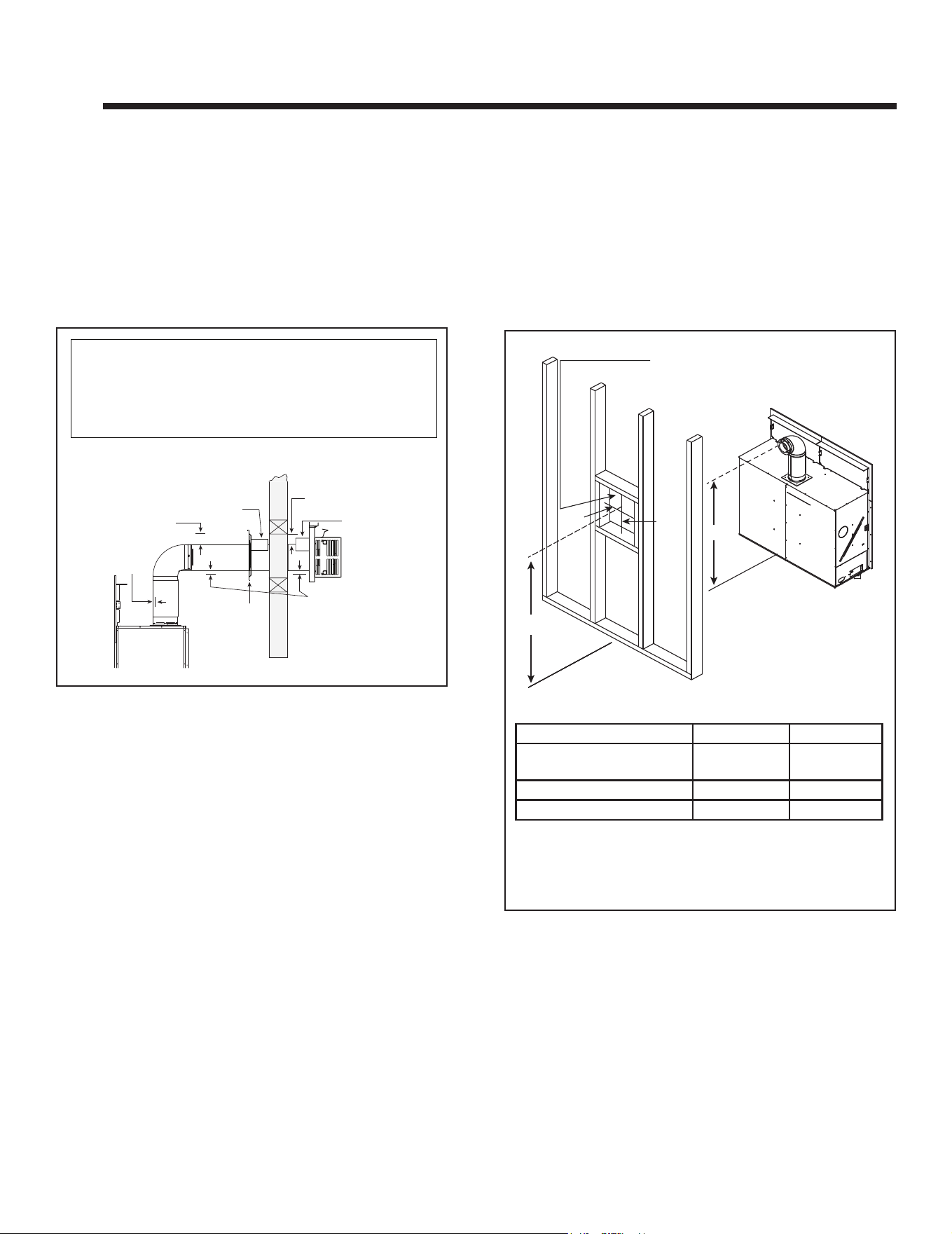
H. PVLP-SLP, PVI-SLP-B and PVV-SLP
Information
This section provides specic detail for installation of
MARQ36IN-B and MARQ42IN-B models with approved
power vent kits. Follow instructions included with the PV-
LP-SLP, PVI-SLP-B and PVV-SLP power vent kits.
See Table 4.1 below for approved Power Venting options
for MARQUIS models.
WARNING! Risk of Fire! Use ONLY Hearth & Home
Technologies-approved power venting systems with this
appliance. Use of power venting systems not approved
by Hearth & Home Technologies may cause replace to
overheat.
PVI-SLP-B
Bafe Adjustment Setting
MARQ36IN-B
MARQ42IN-B
3 Holes Visible
Figure 4.17 Bafe Adjustment Location - PVI-SLP-B
ADJUSTMENT BOLT
INDICATOR BAR
INDICATOR BAR
ADJUSTMENT HOLES
Figure 4.18 Bafe Adjustment - PVI-SLP-B
Table 4.1
WARNING! Risk of Explosion! Follow instructions to
set draft ow. Incorrect setting may impair burner perfor-
mance and/or cause delayed ignition.
PVLP-SLP PVI-SLP-B PVV-SLP
MARQ36IN-B
APPROVED APPROVED APPROVED
MARQ42IN-B
APPROVED APPROVED APPROVED
Table 4.2
The power vent draft ow must be adjusted and set per
the specications in Table 4.2. Refer to the instructions
provided with the PVLP-SLP and PVI-SLP-B for more
specic information.
Setting the PVLP-SLP Bafe Adjustment:
Note: The air bafe may be adjusted after installation.
The bafe adjustment screw can be accessed by removing
the front cap cover.
• If the burner ames are short, active, and jumping, turn
the bolt counterclockwise (open). Check the burner
ames and adjust the bafe again as necessary until
the ames are stable, strong, and steady.
• If the burner ames are tall, lifting, oating, and ghost-
like, the bafe is too far open and MUST be closed.
Turn bolt clockwise.
• If the pilot continuously sparks and does not become
steady, the bafe may need to be opened. The require-
ments in Table 4.2. must still be met.
Distance from PVLP-SLP
to Appliance
Allowable Bafe
Minimum Maximum
2-15 ft. 1-1/2 in. 2-1/2 in.
16-39 ft. Closed 1-1/2 in.
Greater than 40 Closed
PVI-SLP-B: The bafe adjustment is measured using the
holes on the indicator bar of the PVI-SLP-B bafe. This
bar raises as the bafe is opened and lowers as the bafe
is closed. Adjust the bafe by turning the screw located in
the motor enclosure. See Figure 4.17 and 4.18.
Table 4.3
PVV-SLP: It may be necessary to add a ue restrictor to
the appliance when using this powervent. Follow instruc-
tions included with the PVV-SLP powervent.
Majestic MARQ36IN-B, MARQ42IN-B Installation Manual • 2614-980 Rev. P • 5/2228
A. Pipe Clearances to Combustibles
WARNING! Risk of Fire! Maintain air space clearance
to vent. DO NOT pack insulation or other combustibles:
• Between ceiling restops
• Between wall shield restops
• Around vent system
Failure to keep insulation or other material away from
vent pipe may cause overheating and re.
5 5
Vent Clearances and Framing
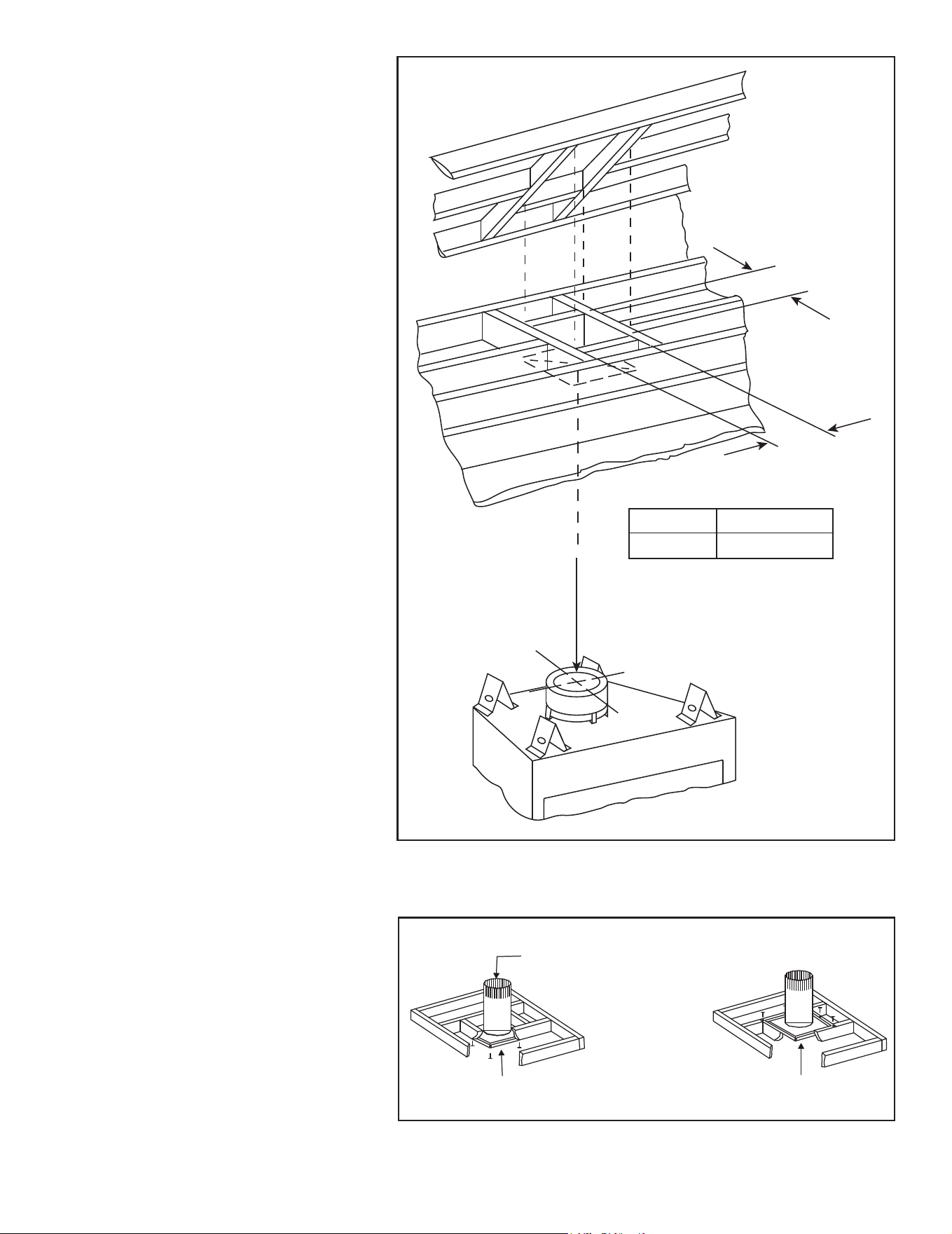
Figure 5.2 Wall Penetration
Figure 5.1 Horizontal Venting Clearances To Combustible
Materials
B. Wall Penetration Framing/Firestops
Combustible Wall Penetration
Whenever a combustible wall is penetrated, you must
frame a hole for the wall shield restop(s). The wall shield
restop maintains minimum clearances and prevents cold
air inltration.
• The opening must be framed on all four sides using the
same size framing materials as those used in the wall
construction.
• DVP pipe - A wall shield restop is required on one side
only on interior walls. If your local inspector requires a
wall shield restop on both sides, then both wall shield
restops must have a heat shield (refer to Section
12.A.) attached to them.
• See Section 7.E. for information for regarding the instal-
lation of a horizontal termination cap.
Note: Heat shields MUST overlap by a minimum of 1-1/2 in. (38 mm).
• DVP heat shield - designed to be used on a wall 4 in. to 7-1/4 in. (102 mm to 184
mm) thick.
• If wall thickness is less than 4 in. the existing heat shields must be field trimmed. If
wall thickness is greater than 7-1/4 in. a DVP-HSM-B will be required.
• If wall thickness is less than 4-3/8 the existing heat shields must be field trimmed.
If wall thickness is greater than 7-5/8 in. a DVP-HSM-B will be required.
(DVP Pipe Shown)
3 in. (76 mm)
top clearance *
1 in. (25 mm)
clearance
bottom & sides
Heat
Shield
Wall
Shield
Firestop
Heat
Shield
WALL
3 in. (76 mm)
top clearance
1 in. (25 mm)
clearance around
vertical sections
A*
B
10 in.
12 in.
DO NOT PACK WITH
INSULATION OR OTHER
MATERIAL
* Shows center of vent framing hole with minimum vertical for top venting. The
center of the hole is one (1) in. (25 mm) above the center of the horizontal
vent pipe.
MODEL A* B
MARQ36IN-B NG/
Propane
74-3/16 in. 73-3/16 in.
MARQ42IN-B NG 79-3/16 in. 78-3/16 in.
MARQ42IN-B Propane 91-3/16 in. 90-3/16 in.
Non-Combustible Wall Penetration
If the hole being penetrated is surrounded by non-com-
bustible materials such as concrete, a hole with diameter
one inch greater than the pipe is acceptable.
Whenever a non-combustible wall is penetrated, the wall
shield restop is only required on one side and no heat
shield is necessary.
29
Majestic MARQ36IN-B, MARQ42IN-B Installation Manual • 2614-980 Rev. P • 5/22
C. Ceiling Firestop/Floor Penetra-
tion Framing
WARNING! Risk of Fire! DO NOT pack insu-
lation around the vent. Maintain clearances to
vent to prevent overheating.
A ceiling restop MUST be used between
oors and attics.
• DVP pipe only - Frame an opening 10 in.
by 10 in. (254 mm by 254 mm) whenever
the vent penetrates a ceiling/oor (see
Figure 5.3).
• Frame the area with the same sized lumber
as used in ceiling/oor joist.
• The ceiling restop may be installed above or
below the ceiling joists when installed with an
attic insulation shield. It must be under joists
between oors that are not insulated. Refer
to Figure 5.4.
• Secure with three fasteners on each side.
WARNING! Risk of Fire! DO NOT pack insu-
lation around the vent. Insulation must be kept
back from the pipe to prevent overheating.
Figure 5.3 Installing Ceiling Firestop
Figure 5.4 Installing the Attic Shield
INSTALL ATTIC INSULATION SHIELDS
BEFORE OR AFTER INSTALLATION OF VENT SYSTEM
CEILING FIRESTOP
INSTALLED BELOW CEILING
CEILING FIRESTOP
INSTALLED ABOVE CEILING
ATTIC ABOVE
A
PIPE
DVP
A
10 in. (254 mm)
A
D. Install Attic Insulation Shield
WARNING! Fire Risk. The use of an attic
shield is required to prevent loose materials
or insulation from contacting the vent causing
overheating and a re.
The International Fuel Gas Code requires an
attic shield constructed of 26 gauge minimum
steel that extends at least 2 in. (51 mm) above
insulation.
• Attic insulation shields must meet specied
clearances to combustible materials and be
secured in place.
• An attic insulation shield kit is available from
Hearth & Home Technologies. Contact your
dealer to order. Install attic insulation shield
according to instructions included with kit.
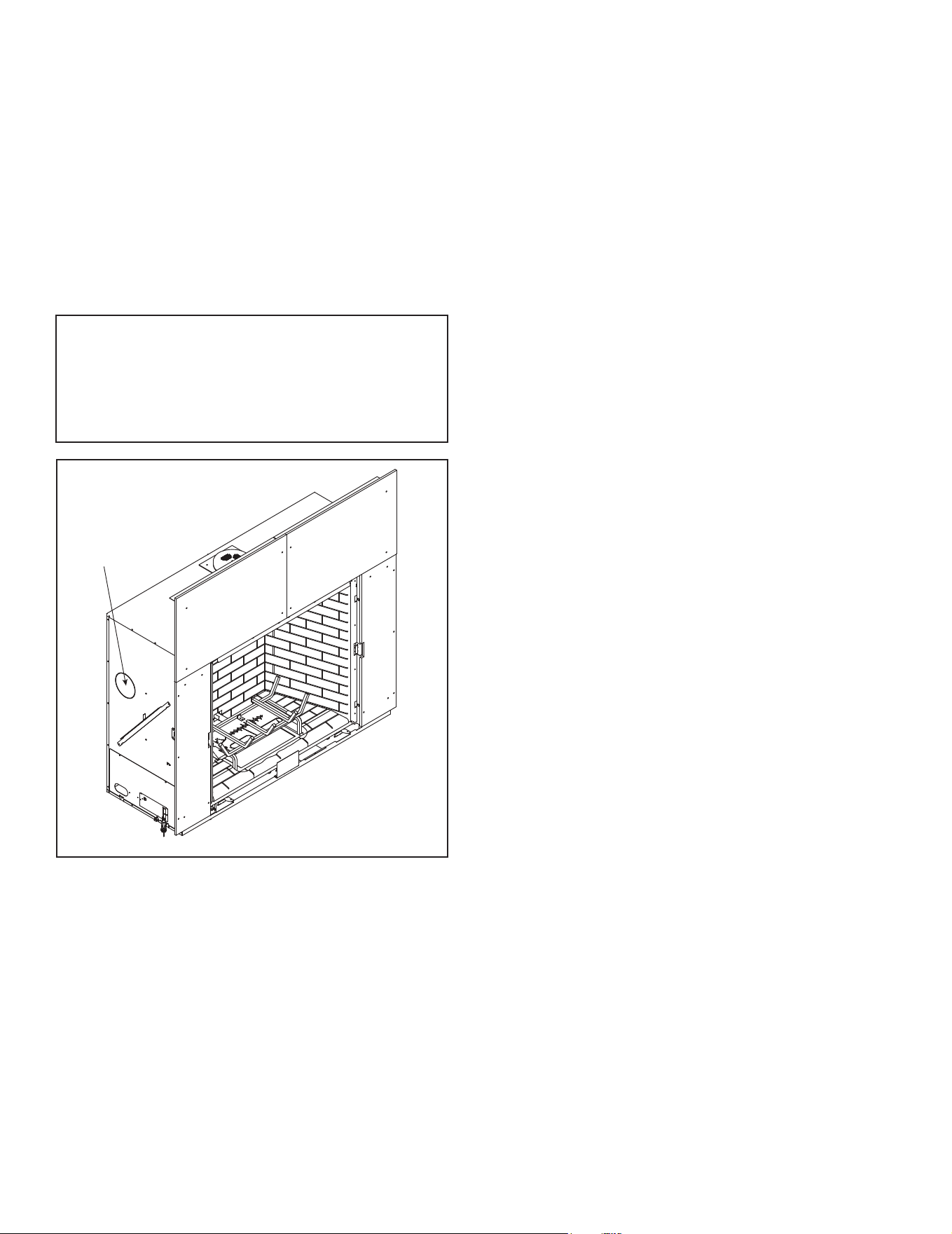
Majestic MARQ36IN-B, MARQ42IN-B Installation Manual • 2614-980 Rev. P • 5/2230
KNOCKOUT LOCATION
LEFT AND RIGHT SIDES
E. Installing the Optional Heat Management
• Locate the knockouts on the left and right sides of the
appliance. See Figure 5.5. Remove the knockouts from
the appliance with a tin snips.
• Center the duct collar around the exposed hole and
attach it to the appliance with 3 screws. Note: Do this
BEFORE nal positioning of the appliance.
• Determine the location for the air register/fan housing
assembly.
Reference the appropriate instructions included with the
kit for the remaining installation steps.
Figure 5.5 Knockout Cover Plate
Note: Only one heat management kit may be used
with this appliance, and be controlled through the IFT
remote control. An additional heat managment kit may
be added, however it is recommended to be wired
through the appliance junction box. Reference the
heat management instructions for installation.
31
Majestic MARQ36IN-B, MARQ42IN-B Installation Manual • 2614-980 Rev. P • 5/22
A. Vent Collar Preparation
6 6
Appliance Preparation
SEAL CAPSEAL CAP
GASKETGASKET
Figure 6.2 Seal Cap and Gasket Location
CAUTION! Risk of Cuts, Abrasions or Flying Debris.
Wear protective gloves and safety glasses during instal-
lation. Sheet metal edges are sharp.
NOTICE: This appliance is top vented ONLY.
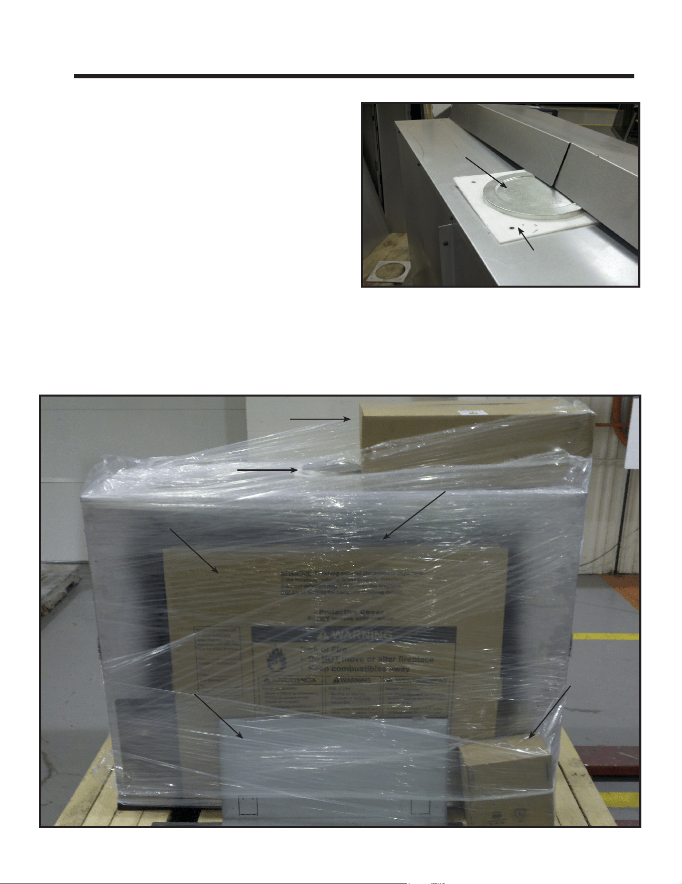
1. Remove shrink wrap from appliance. Figure 6.1 shows
the shipping location of the seal cap and heat shields
(Section 6), splatter guard and nishing templates
(Section 10), and the logs (Section 11).
2. Remove seal cap from top of appliance by removing
one screw, which is included, to prevent construction
material from getting into appliance. Remove seal cap
when pipe installation phase begins. See Figure 6.2.
3. Ensure gasket seal is in place prior to installing vent
pipe sections. Gasket is installed at the factory.
Figure 6.1 Shipping Location of Components
SEAL CAPSEAL CAP
LOGSLOGS
SPLATTER GUARDSPLATTER GUARD
FINISHING FINISHING
TEMPLATESTEMPLATES
TECO-SILTECO-SIL
HEADER HEAT SHIELDSHEADER HEAT SHIELDS
(SHIPPED ON REAR SIDE OF APPLIANCE(SHIPPED ON REAR SIDE OF APPLIANCE
Majestic MARQ36IN-B, MARQ42IN-B Installation Manual • 2614-980 Rev. P • 5/2232
B. Securing and Leveling the Appliance
WARNING! Risk of Fire! Prevent contact with:
• Sagging or loose insulation
• Insulation backing or plastic
• Framing and other combustible materials
Block openings into the chase to prevent entry of blown-
in insulation. Make sure insulation and other materials
are secured.
DO NOT notch the framing around the appliance
standoffs.
Failure to maintain air space clearance may cause
overheating and re.
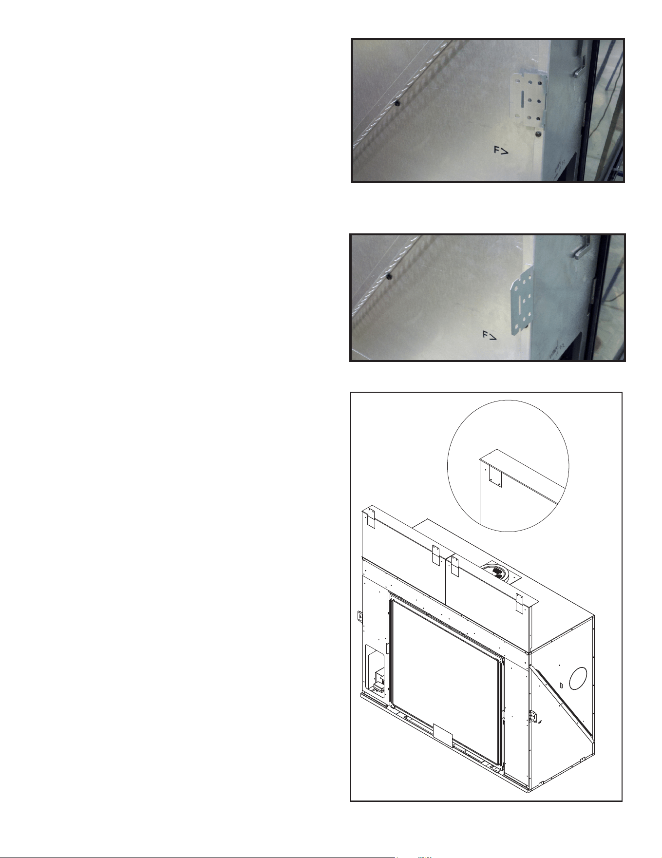
Figure 6.3 Side Nailing Tab in Shipping Position
Figure 6.4 Nailing Tab Bent Out for Installation
Figure 6.5. Heat Shields and Nailing Tabs in Installation Position
HEAT SHIELD NAILING
TAB IN SHIPPING
POSITION
Nailing tabs are provided on the appliance and on the heat
shields to secure the appliance to the framing members.
See Figure 6.3 and Figure 6.5 for location of nailing tabs
in shipping position.
• Bend out side nailing tabs 90 degrees. See Figure 6.4.
• Place the appliance into position.
• Keep side nailing tabs ush with the framing.
• Level the appliance from side to side and front to back.
• Shim the appliance as necessary. It is acceptable to use
wood shims underneath the appliance.
• Position and install heat shields by securing two screws
in each heat shield. See Figure 6.1 for shipping location
of heat shields. The heat shield screws can be found
pre-installed on the top of the appliance.
• Bend the top header heat shields upward to position
them vertically and bend out the two nailing tabs on the
top of each header heat shield. Secure to framing. See
Figure 6.5.
• Secure the appliance to the framing by using nails or
screws through the nailing tabs.
• Secure the appliance to the oor by inserting two screws
through the pilot holes at the bottom of the appliance.
33
Majestic MARQ36IN-B, MARQ42IN-B Installation Manual • 2614-980 Rev. P • 5/22
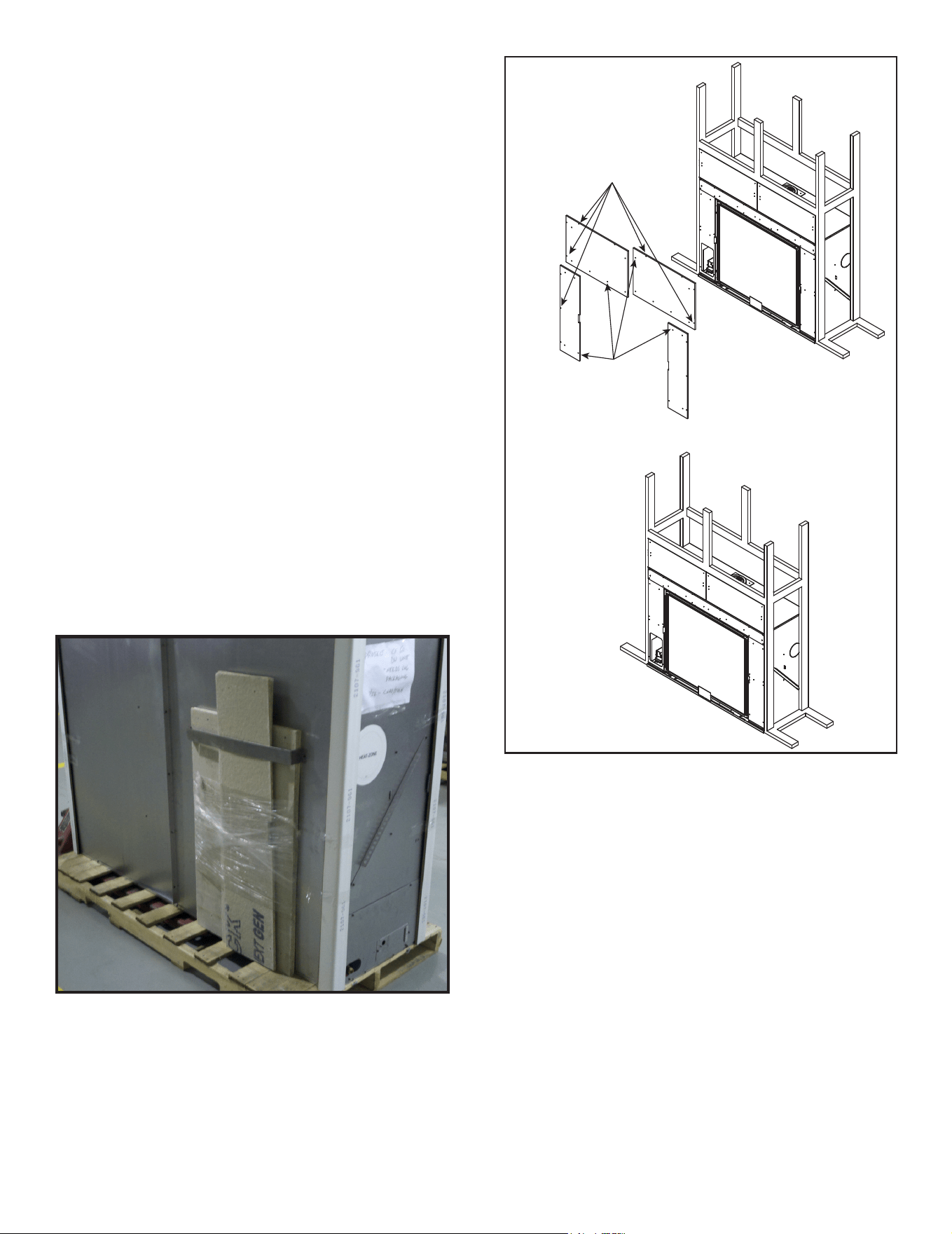
Figure 6.6 Shipping Location of Non-Combustible Board
C. Installing Non-Combustible Facing Material
WARNING! Risk of Fire!
• Follow these instructions exactly.
• Facing materials must be installed properly to prevent
re.
• No materials may be substituted without authorization
by Hearth & Home Technologies.
PERIMETER:
SECURE TO FRAMING WITH
DRYWALL SCREWS OR NAILS
(NOT INCLUDED)
INTERIOR:
SECURE WITH
SELF-TAPPING SCREWS
(IN MANUAL BAG ASSEMBLY)
Figure 6.7 Installing Non-Combustible Facing Material
• The nishing templates are shipped fastened to the top
surround. Remove nishing templates prior to installing
non-combustible board.
• Remove non-combustible facing pieces from back of
appliance. See Figure 6.6.
• Install non-combustible facing material to the appliance
using the screws supplied in the manual bag assembly.
• Center and attach two top boards to the framing
members. See Figure 6.7.
• Attach left and right side pieces to framing members.
• Use fasteners from fastener packet (in manual bag) for
screws that secure to the replace. See Figure 6.7.
• Use regular sheetrock screws or nails to secure the
perimeter of the non-combustible facing materials to the
wood framing. See Figure 6.7.
• Use a wet or dry towel or soft brush to remove dust or
dirt from facing material.
• See Section 10 for nishing materials guidelines.

Majestic MARQ36IN-B, MARQ42IN-B Installation Manual • 2614-980 Rev. P • 5/2234
A. Assemble Vent Sections (DVP Pipe Only)
Attach Vent to the Firebox Assembly
Note: The end of the pipe sections with the lanced tabs
will face toward the appliance.
Attach the rst pipe section to the starting collar:
• Lanced pipe end of the starting collar.
• Inner pipe over inner collar.
• Push the pipe section until all lanced tabs snap in place.
• Lightly tug on pipe to conrm it has locked.
7 7
Venting and Chimneys
Assemble Pipe Sections
Per Figure 7.2:
• Start the inner pipe on the lanced end of section A into
the ared end of section B.
• Start the outer pipe of section A over the outer pipe of
section B.
• Once both vents sections are started, push rmly until
all lanced tabs lock into place.
• Lightly tug on the pipe to conrm the tabs have locked.
It is acceptable to use screws no longer than 1/2 in. (13
mm) to hold outer pipe sections together. If predrilling holes,
DO NOT penetrate inner pipe.
For 90º and 45º elbows that are changing the vent direction
from horizontal to vertical, one screw minimum should be put
in the outer ue at the horizontal elbow joint to prevent the
elbow from rotating. Use screws no longer than 1/2 in. (13
mm). If predrilling screw holes, DO NOT penetrate inner pipe.
All outer pipe joints must be sealed using one of the meth-
ods below, including the slip section that connects directly
to the horizontal termination cap.
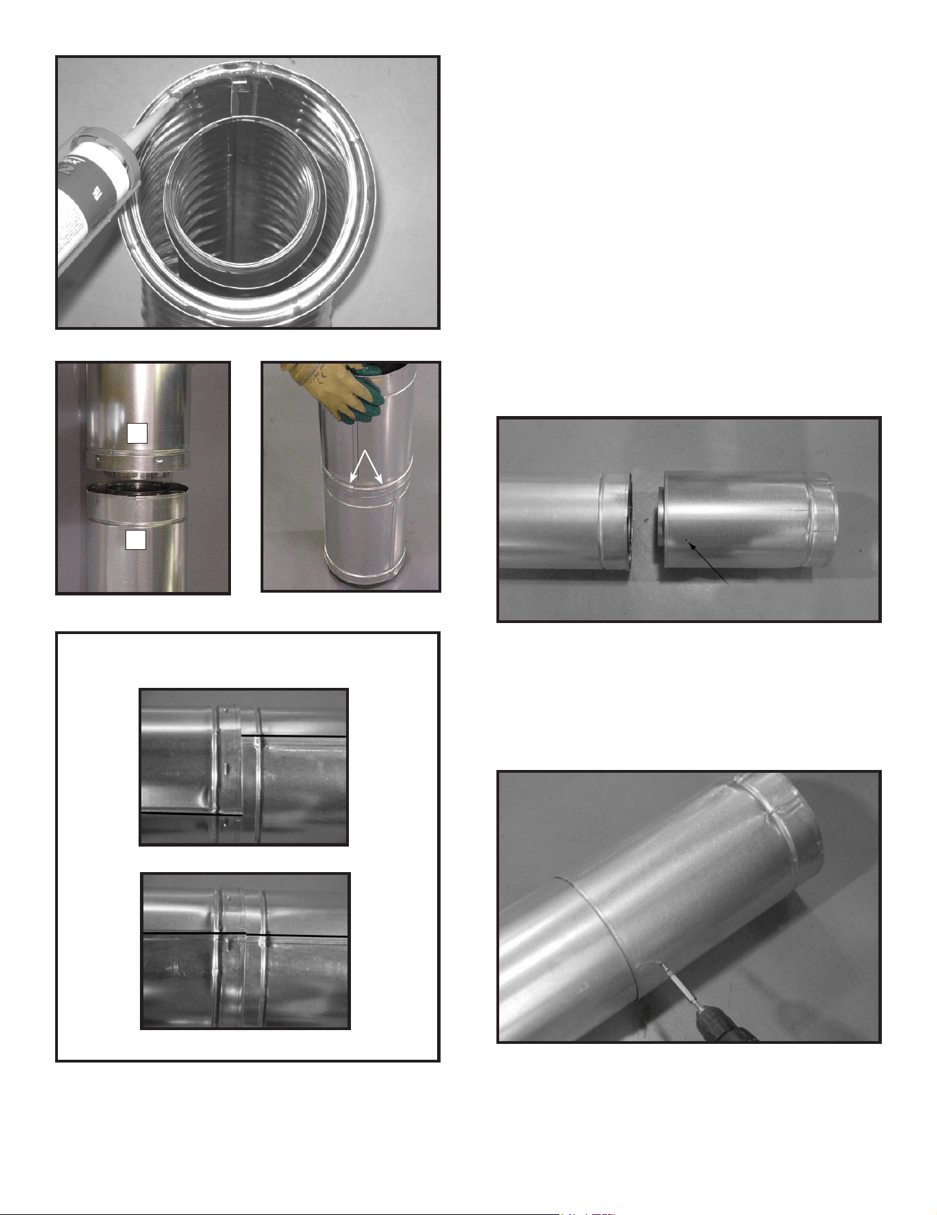
• Apply a bead of silicone sealant (300 ºF minimum con-
tinuous exposure rating) inside the female outer pipe
joint prior to joining sections. See Figure 7.1 OR
Apply a bead of silicone sealant (300 ºF minimum con-
tinuous exposure rating) to the outside of connecting
joint after joining sections OR
Apply aluminum foil tape (300 ºF minimum continuous
exposure rating) to the outside of connecting joint after
joining sections. On horizontal pipe runs, it is recom-
mended that the tape seam is positioned on the bottom
side of the vent pipe.
• Only outer pipes need to be sealed. All unit collar, pipe,
slip section, elbow and cap outer ues shall be sealed
in this manner, unless otherwise stated.
WARNING! Risk of Fire or Explosion! DO NOT break
silicone seals on slip sections. Use care when remov-
ing termination cap from slip pipe. If slip section seals
are broken during removal of the termination cap, vent
could leak.
WARNING! Risk of Fire or Explosion! Vent sections
MUST be installed correctly. Improperly installed vent
sections could leak or cause appliance to overheat.
Requirement for Commercial, Multi-family (Multi-level ex-
ceeding two stories), or High-Rise Applications
35
Majestic MARQ36IN-B, MARQ42IN-B Installation Manual • 2614-980 Rev. P • 5/22
Figure 7.1 High Temperature Silicone Sealant
Figure 7.2
A
B
Figure 7.3
Figure 7.4 Seams
Note: Make sure that the seams are not aligned to prevent
unintentional disconnection.
INCORRECT
CORRECT
LancesLances
NOTICE: When installing a vent system with an HRC
termination cap, all pipe system joints shall be sealed
using a high temperature silicone sealant (300 ºF minimum
continuous exposure rating).
• Apply a bead of silicone sealant (300 ºF minimum
continuous exposure rating) inside the female outer pipe
joint prior to joining sections.
• Only outer pipes are sealed, sealing the inner ue is not
required.
• All unit collar, pipe, slip section, elbow and cap outer
ues shall be sealed.
B. Assemble Slip Sections
• Slide the inner ue of the slip section into the inner ue
of the pipe section and the outer ue of the slip section
over the outer ue of the pipe section. See Figure 7.5.
• Slide together to the desired length.
Figure 7.5 Slip Section Pilot Holes
Figure 7.6 Screws into Slip Section
Pilot holePilot hole
• Continue adding pipe as necessary following instructions
in “Assembling Pipe Sections.”
NOTICE: If slip section is too long, the inner and outer
ues of the slip section can be cut to the desired length.
• Maintain a 1-1/2 in. (38 mm) overlap between the slip
section and the pipe section.
• Secure the pipe and slip section with two screws no
longer than 1/2 in. (13 mm), using the pilot holes in the
slip section. See Figure 7.6.
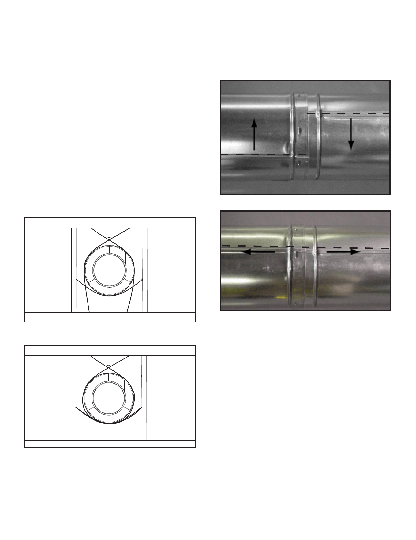
Majestic MARQ36IN-B, MARQ42IN-B Installation Manual • 2614-980 Rev. P • 5/2236
120º
Figure 7.7 Securing Vertical Pipe Sections
120º
Figure 7.8 Securing Horizontal Pipe Sections
D. Disassemble Vent Sections
• Rotate either section (see Figure 7.9) so the seams on
both pipe sections are aligned as shown in Figure 7.10.
• Pull carefully to separate the pieces of pipe.
Figure 7.10 Align and Disassemble Vent Sections
Figure 7.9 Rotate Seams for Disassembly
C. Secure the Vent Sections
• Vertical runs originating off the top of the appliance, with
no offsets, must be supported every 8 ft. (2.44 m) after
the maximum allowed 25 ft. (7.62 m) of unsupported rise.
• Vertical runs originating off the rear of the appliance, or
after any elbow, must be supported every 8 ft. (2.44 m).
• Horizontal runs must be supported every 5 feet (1.52
m).
• Vent supports or plumbers strap (spaced 120º apart)
may be used to support vent sections. See Figures 7.7
and 7.8.
• Wall shield restops may be used to provide horizontal
support to vent sections.
• SLP ceiling restops have tabs that may be used to
provide vertical support.
WARNING! Risk of Fire, Explosion or Asphyxiation!
Improper support may allow vent to sag and separate.
Use vent run supports and connect vent sections per in-
stallation instructions. DO NOT allow vent to sag below
connection point to appliance.
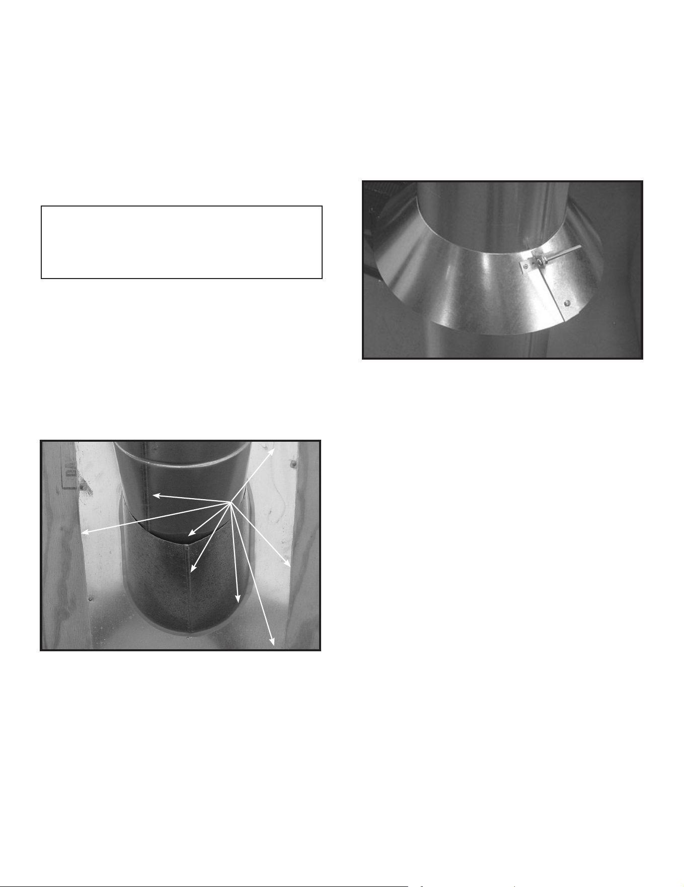
37
Majestic MARQ36IN-B, MARQ42IN-B Installation Manual • 2614-980 Rev. P • 5/22
SEAL
Figure 7.11
Figure 7.12 Insert Bolt into Brackets
Assemble and Install Storm Collar
CAUTION! Risk of Cuts, Abrasions or Flying Debris.
Wear protective gloves and safety glasses during instal-
lation. Sheet metal edges are sharp.
• Slide the storm collar onto the exposed pipe section
and align brackets.
• Insert a bolt (provided) through the brackets and install
nut. Do not completely tighten.
• Slide the assembled storm collar down the pipe section
until it rests on the roof ashing. See Figure 7.12.
• Tighten nut and make sure the collar is tight against the
pipe section.
• Seal around the top of the storm collar. See Figure 7.13.
E. Vertical Termination Requirements
Install and Seal Metal Roof Flashing
• See minimum vent heights for various pitched roofs
(Section 4, Figure 4.1) to determine the length of pipe
to extend through the roof.
• Slide the roof ashing over the pipe sections extending
through the roof as shown in Figure 7.11.
• Use an elastomeric or silicone sealant with a minimum of
150 ºF temperature rating to seal the metal roof ashing.
NOTICE: Failure to properly seal the roof ashing and pipe
seams could permit entry of water.
• Seal the gap between the roof ashing and the outside
diameter of the pipe.
• Seal the perimeter of the ashing where it contacts the
roof surface. See Figure 7.11.
• Seal the exposed pipe section seams that are located
above the roof.
Note: When installing a silicone or EPDM pipe ashing boot
on a metal roof, it is recommended to put a bead of 100%
silicone sealant where the boot contacts the vent pipe to
prevent the entry of water. Follow the manufacturer’s recom-
mendations when installing the boot.
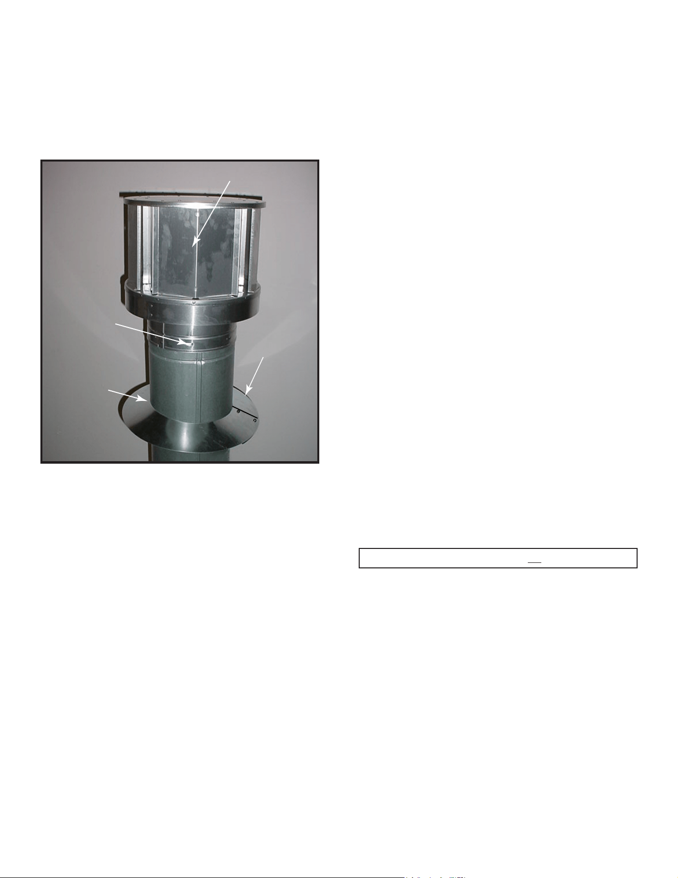
Majestic MARQ36IN-B, MARQ42IN-B Installation Manual • 2614-980 Rev. P • 5/2238
Figure 7.13 Venting through the wall
Install Vertical Termination Cap
• Attach the vertical termination cap by sliding the inner
collar of the cap into the inner ue of the pipe section
while placing the outer collar of the cap over the outer
ue of the pipe section.
• Secure the cap by driving three self-tapping screws
(supplied) through the pilot holes in the outer collar of
the cap into the outer ue of the pipe. See Figure 7.13.
Termination Cap
(1 of 3)
Storm
Collar
Seal
Screws
Figure 7.13
Important Notice: Heat shields may not be eld constructed.
F. Horizontal Termination Requirements
Heat Shield Requirements for Horizontal
Termination
WARNING! Risk of Fire! To prevent overheating and re,
heat shields must extend through the entire wall thick-
ness.
• DO NOT remove the heat shields attached to the
wall shield restop and the horizontal termination cap
(shown in Figure 7.14).
• Heat shields must overlap 1-1/2 in. (38 mm) mini-
mum.
There are two sections of the heat shield. One section
is factory-attached to the wall shield restop. The other
section is factory-attached to the cap. See Figure 7.16.
If the wall thickness does not allow the required 1-1/2 in.
(38 mm) heat shield overlap when installed, an extended
heat shield must be used.
• If the wall thickness is less than 4 in./102 mm (DVP)
or 4-3/8 in./ 111 mm (SLP), the heat shields on the cap
and wall shield restop must be trimmed. A minimum
1-1/2 in. (38 mm) overlap MUST be maintained.
• Use an extended heat shield if the nished wall
thickness is greater than 7-1/4 in. (184 mm).
• The extended heat shield may need to be cut to length
maintaining sufcient length for a 1-1/2 in. (38 mm)
overlap between heat shields.
• Attach the extended heat shield to either of the existing
heat shields using the screws supplied with the extended
heat shield. Refer to vent components diagrams in the
back of this manual.
• Rest the small leg on the extended heat shield on top
of the pipe section to properly space it from the pipe
section.
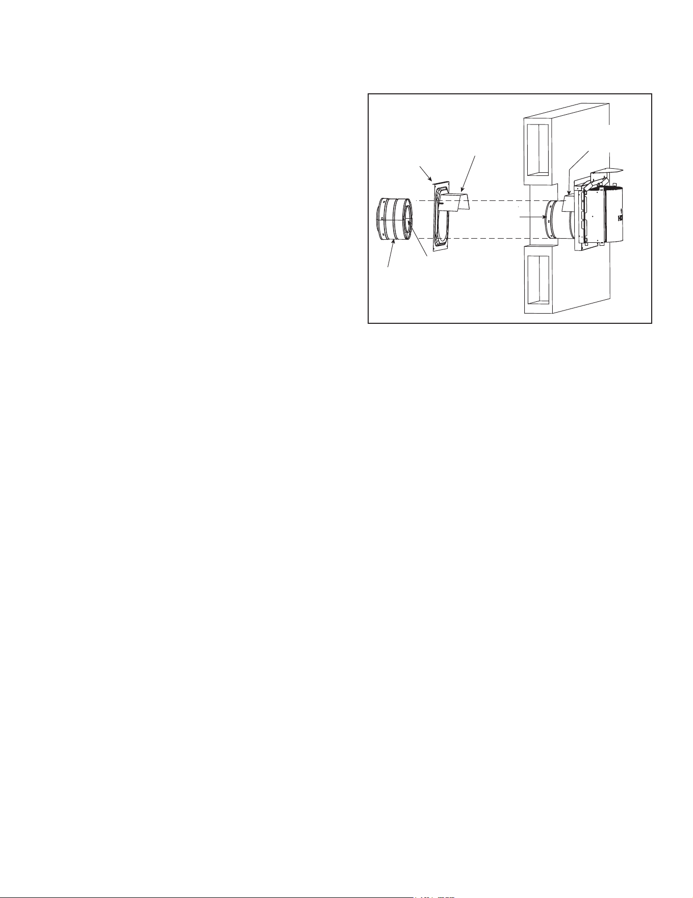
39
Majestic MARQ36IN-B, MARQ42IN-B Installation Manual • 2614-980 Rev. P • 5/22
INTERIOR
HEAT SHIELD OR
EXTENDED
HEAT SHIELD
WALL SHIELD
FIRESTOP
HEAT SHIELD
1-1/2 IN. (38 MM) MIN.
OVERLAP
SHEATHING
SLIP SECTION
CAN BE EXTENDED
INNER VENT
OUTER VENT
EXTERIOR
Note: When using termination caps with factory-supplied
heat shield attached, no additional wall shield restop is
required on the exterior side of a combustible wall.
Install Horizontal Termination Cap
WARNING! Risk of Fire! The telescoping ue section of
the termination cap MUST be used when connecting vent.
• 1-1/2 (38 mm) minimum overlap of ue telescoping
section is required.
Failure to maintain overlap may cause overheating and
re.
• Vent termination must not be recessed in the wall. Siding
may be brought to the edge of the cap base.
• Flash and seal as appropriate for siding material at
outside edges of cap.
• When installing a horizontal termination cap, follow
the cap location guidelines as prescribed by current
ANSI Z223.1 and CAN/CGA-B149 installation codes
and refer to Section 4 of this manual.
CAUTION! Risk of Burns! Local codes may require in-
stallation of a cap shield to prevent anything or anyone
from touching the hot cap.
NOTICE: For certain exposures which require superior
resistance to wind-driven rain penetration, a ashing kit
and HRC caps are available. When penetrating a brick
wall, a brick extension kit is available for framing the brick.
Figure 7.14 Venting Through the Wall
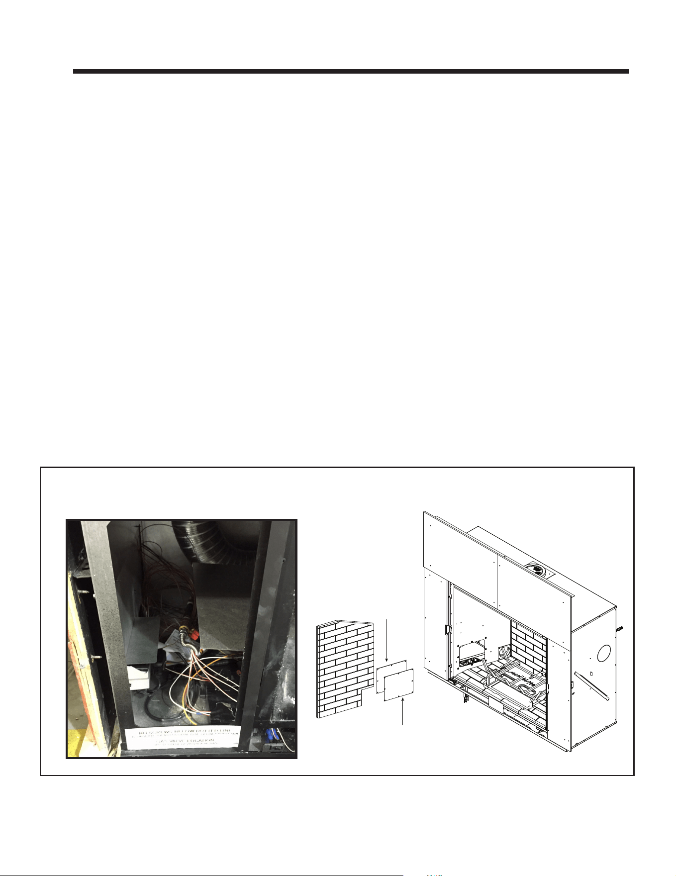
Majestic MARQ36IN-B, MARQ42IN-B Installation Manual • 2614-980 Rev. P • 5/2240
A. General Information
WARNING! Risk of Shock! DO NOT wire 110-120 VAC
to the valve or to the appliance wall switch. Incorrect wir-
ing will damage controls.
NOTICE: This appliance must be electrically wired
and grounded in accordance with local codes or, in the
absence of local codes, with National Electric Code
ANSI/NFPA 70-latest edition or the Canadian Electric
Code CSA C22.1.
• Wire the appliance circuit using a minimum 14-2 AWG
with ground to unswitched 110-120 VAC. This is required
for proper operation of the appliance.
• A 110-120 VAC circuit for this product must be protected
with ground-fault circuit-interrupter protection, in
compliance with the applicable electrical codes, when
it is installed in locations such as in bathrooms or near
sinks.
• Low voltage and 110-120 VAC voltage cannot be shared
within the same wall box.
8 8
Electrical Information
Junction Box Installation
The electrical junction box can be accessed three ways
during installation:
1. Through the side electrical access:
• Remove two screws to release junction box bracket
from the access plate. See Figure 3.2 and Figure
8.2.
2. Through the front left column (behind the factory-
installed non-combustible board):
• From inside remove one screw that secures junction
box to junction box bracket. See Figure 8.1 and
Figure 8.2.
3. Through the rebox:
• From inside remove one screw that secures junction
box to junction box bracket. See Figure 8.1 and
Figure 8.2.
• Pull the electrical wires from outside the appliance
through the opening into the valve compartment and
secure wires with a Romex connector. See Figure 8.2
• Make all necessary wire connections to the junction
box/receptacle and reattach the junction box/receptacle
to the outer shell.
Figure 8.1 Junction Box Access
GASKET
COVER
ACCESS THROUGH LEFT COLUMN
(Prior to installation of non-combustible board)
ACCESS THROUGH FIREBOX
(After installation of non-combustible board)
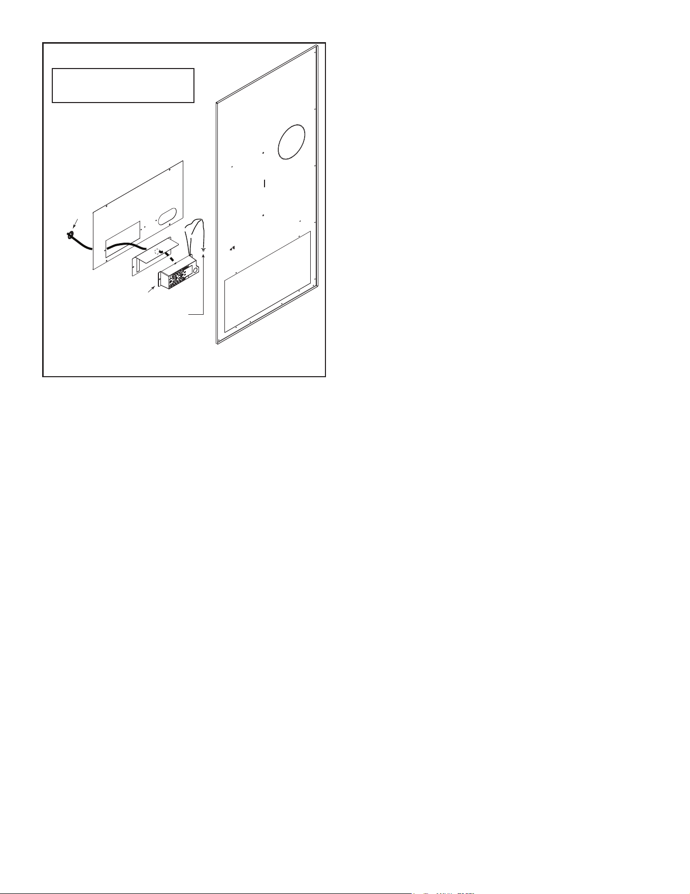
41
Majestic MARQ36IN-B, MARQ42IN-B Installation Manual • 2614-980 Rev. P • 5/22
Accessories Requirements
• This appliance may be used with a wall switch, wall
mounted thermostat and/or a remote control.
Wiring for optional Hearth & Home Technologies approved
accessories should be done now to avoid reconstruction.
Follow instructions that come with those accessories.
• Hearth & Home Technologies recommends that Intel-
liFire
TM
Touch wireless controls be used for their fea-
tures and functionality with the IntelliFire
TM
Touch igni-
tion system.
Figure 8.2 Junction Box Detail
Electrical Service and Repair
WARNING! Risk of Shock! Label all wires prior to dis-
connection when servicing controls. Wiring errors can
cause improper and dangerous operation. Verify proper
operation after servicing.
WARNING! Risk of Shock! Replace damaged wire with
type 105º C rated wire. Wire must have high temperature
insulation.
GRN wire
inside box
Copper ground
attached to GRN
screw with GRN wire
WHT
WHT
BLK
BLK
14/2WG
Romex
Connector
NOTICE: DO NOT wire
110-120 VAC to wall switch.
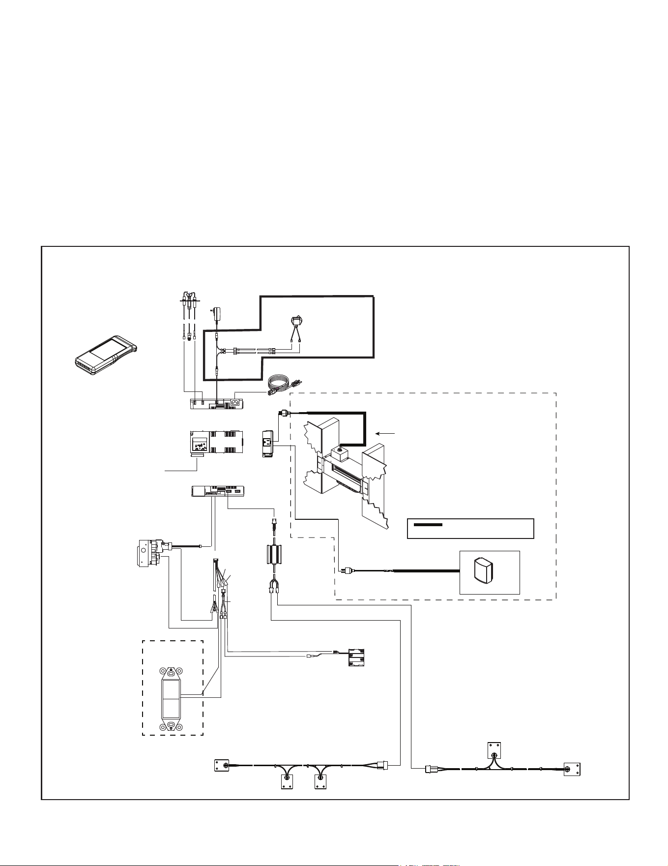
Majestic MARQ36IN-B, MARQ42IN-B Installation Manual • 2614-980 Rev. P • 5/2242
B. Wiring Requirements
IntelliFire
Touch
®
Ignition System Wiring
NOTICE: Batteries should only be used as a power source
in the event of an emergency power outage. Batteries
should not be used as a primary long-term power source.
Battery polarity must be correct when installing batteries.
When using batteries as a power source, the 6-volt
transformer must be unplugged from the receptacle.
Do not store batteries in the battery pack when the
appliance is powered by the 6 volt transformer connected
to permanent electrical service.
• Wire the appliance junction box to 110-120 VAC for
proper operation of the appliance.
WARNING! Risk of Shock or Explosion! DO NOT wire
IFT controlled appliance junction box to a switched circuit.
Incorrect wiring will override IFT safety lockout.
• Refer to Figure 8.3 or 8.4, IFT Wiring Diagram.
• This appliance is equipped with an IntelliFire Touch
control valve which operates on a 6 volt/1.5 AMP system.
• Plug the 6 volt transformer plug into the appliance junction
box to supply power to the unit OR install 4 AA cell
batteries (not included) into the battery pack before use.
Figure 8.3 IFT Wiring Diagram without Power Vent
FLAME
SENSE
IGNITER
TO JUNCTION
BOX 110-120
VAC
LED
CONTROL
RF MODULE
ADAPTER
I
S
6 PIN
6V DC
BATTERY PACK
BLK
RED
ORANGE
(PILOT)
GREEN
(MAIN)
IFT-RC400
REMOTE
CONTROL
GRN/WHT/BLK
RED/BLK
RED/BLK
BLK
RED
BRN
WIRE ASSEMBLY
MODULE
RESET
SWITCH
SPLITTER
BLK
RED
APPLIANCE
ON/OFF
CONTROL
BLK
REAR ACCENT LIGHTING (X 2)
BLACK/RED
OPTIONAL HEAT-ZONE-GAS or HEAT-OUT-GAS KIT
Optional HEAT-ZONE-GAS kit shown wired
to IFT-ACM. Appliance must be re-paired if
adding a HEAT-ZONE-GAS or HEAT-OUT-GAS
to the IFT-ACM.
Wiring MUST be performed by a certified
electrician.
Thick line denotes wiring
supplied by electrician.
HEAT-OUT-GAS
WIRE PLUG ASSEMBLY
26D0619
WIRE PLUG ASSEMBLY
26D0619
IntelliFire Touch System Wiring Diagram - without Power Vent
FOR PROPANE ONLY
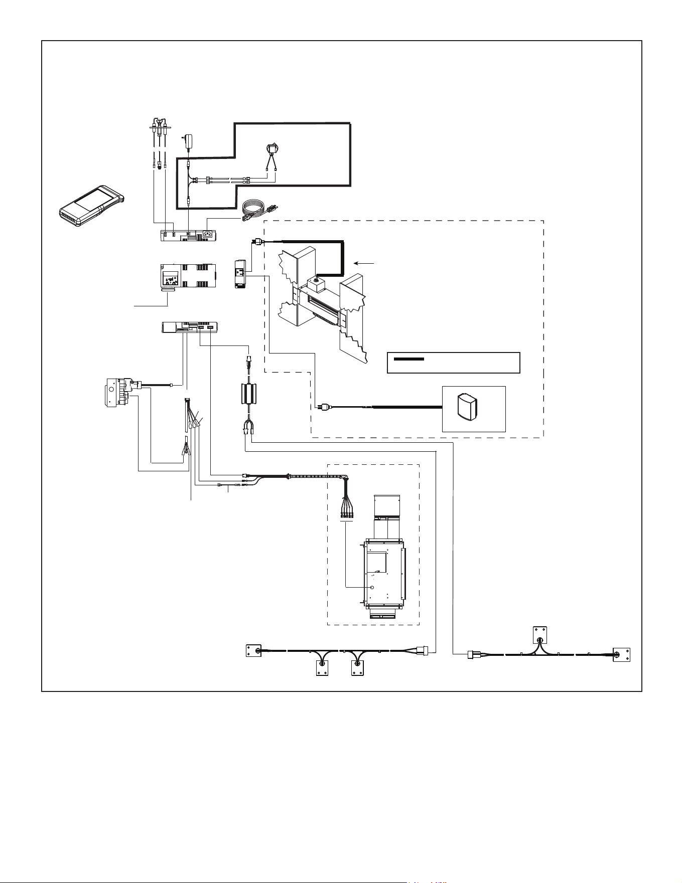
43
Majestic MARQ36IN-B, MARQ42IN-B Installation Manual • 2614-980 Rev. P • 5/22
Figure 8.4 IFT Wiring Diagram with Power Vent
FLAME
SENSE
IGNITER
TO JUNCTION
BOX 110-120
VAC
LED
CONTROL
RF MODULE
ADAPTER
I
S
6 PIN
RED
BLK
ORANGE
(PILOT)
GREEN
(MAIN)
GRN/WHT/BLK
RED/
BLK
RED/
BLK
IFT-RC400
REMOTE
CONTROL
RED
BLK
BRN
BRN
JUMPER WIRE
BRN
WIRE ASSEMBLY
MODULE
RESET
SWITCH
ACCESSORY CABLE
POWER VENT
(OPTIONAL)
(PVI-SLP-B SHOWN)
REAR ACCENT LIGHTING (X 2)
BLACK/RED
OPTIONAL HEAT-ZONE-GAS or HEAT-OUT-GAS KIT
Optional HEAT-ZONE-GAS kit shown wired
to IFT-ACM. Appliance must be re-paired if
adding a HEAT-ZONE-GAS or HEAT-OUT-GAS
to the IFT-ACM.
Wiring MUST be performed by a certified
electrician.
Thick line denotes wiring
supplied by electrician.
HEAT-OUT-GAS
WIRE PLUG ASSEMBLY
26D0619
WIRE PLUG ASSEMBLY
26D0619
IntelliFire Touch System Wiring Diagram - with Power Vent
FOR PROPANE ONLY
Majestic MARQ36IN-B, MARQ42IN-B Installation Manual • 2614-980 Rev. P • 5/2244
9 9
Gas Information
A. Fuel Conversion
• Make sure the appliance is compatible with available gas
types.
• Conversions must be made by a qualified service
technician using Hearth & Home Technologies specied
and approved parts.
B. Gas Pressure
C. Gas Connection
• Refer to Section 3 for location of gas line access in
appliance.
• Gas line may be run through knockout(s) provided.
• The gap between supply piping and gas access hole
may be sealed with caulk or aluminum foil tape with a
minimum of 300 ºF continuous exposure rating or stuffed
with non-combustible, unfaced insulation to prevent cold
air inltration.
• Ensure that gas line does not come in contact with outer
wrap of the appliance. Follow local codes.
• Pipe incoming gas line into valve compartment.
• Connect incoming gas line to the 1/2 in. (13 mm) NPT
connection on manual shutoff valve.
WARNING! Risk of Fire or Explosion! Support control
when attaching pipe to prevent bending gas line.
WARNING! Risk of Fire or Explosion! Gas build-up
during line purge could ignite.
• A small amount of air will be in the gas supply lines.
• Ensure adequate ventilation.
• Ensure there are no ignition sources such as sparks or
open ames.
Light the appliance. It will take a short time for air to purge
from lines. When purging is complete the appliance will
light and operate normally.
WARNING! Risk of Fire, Explosion or Asphyxiation!
Check all ttings and connections with a non-corrosive
commercially available leak-check solution. DO NOT use
open ame. Fittings and connections could have loos-
ened during shipping and handling.
• Verify inlet pressures. Verify minimum pressures when
other household gas appliances are operating.
• Install regulator upstream of valve if line pressure is
greater than 1/2 psig.
Gas Pressure Natural Gas Propane
Minimum inlet pressure 5.0 in. w.c. 11.0 in. w.c.
Maximum inlet pressure 10.0 in. w.c. 13.0 in. w.c.
Manifold pressure 3.5 in. w.c. 10.0 in. w.c.
Note: Have the gas supply line installed in accordance with
local codes, if any. If not, follow ANSI Z223.1. Installation
should be done by a qualied installer approved and/or
licensed as required by the locality. (In the Commonwealth
of Massachusetts installation must be performed by a
licensed plumber or gas tter).
Note: A listed (and Commonwealth of Massachusetts ap-
proved) 1/2 in. (13 mm) T-handle manual shut-off valve
and exible gas connector are connected to the 1/2 in. (13
mm) control valve inlet.
• If substituting for these components, please consult
local codes for compliance.
Fire Risk.
Risk of Fire! Risk of Explosion!
Incorrect pressure will damage valve.
• Isolate gas supply piping BEFORE pressure
testing gas line at test pressures above 1/2
psig.
• Close the manual shutoff valve BEFORE
pressure testing gas line at test pressures
equal to or less than 1/2 psig.
WARNING
D. High Altitude Installations
NOTICE: If the heating value of the gas has been reduced,
these rules do not apply. Check with your local gas utility
or authorities having jurisdiction.
When installing above 2000 feet elevation:
• In the USA: Reduce input rate 4% for each 1000 feet
above 2000 feet.
• In CANADA: Input ratings are certied without a
reduction of input rate for elevations up to 4500 feet
(1370 m)above sea level. Please consult provincial and/
or local authorities having jurisdiction for installations at
elevations above 4500 feet (1370 m).
Check with your local gas utility to determine proper
orice size.
• Optimum appliance performance requires proper input
pressures.
• Gas line sizing requirements will be determined in ANSI
Z223.1 National Fuel Gas Code in the USA and CAN/
CGA B149 in Canada.
• Pressure requirements when in operation are:
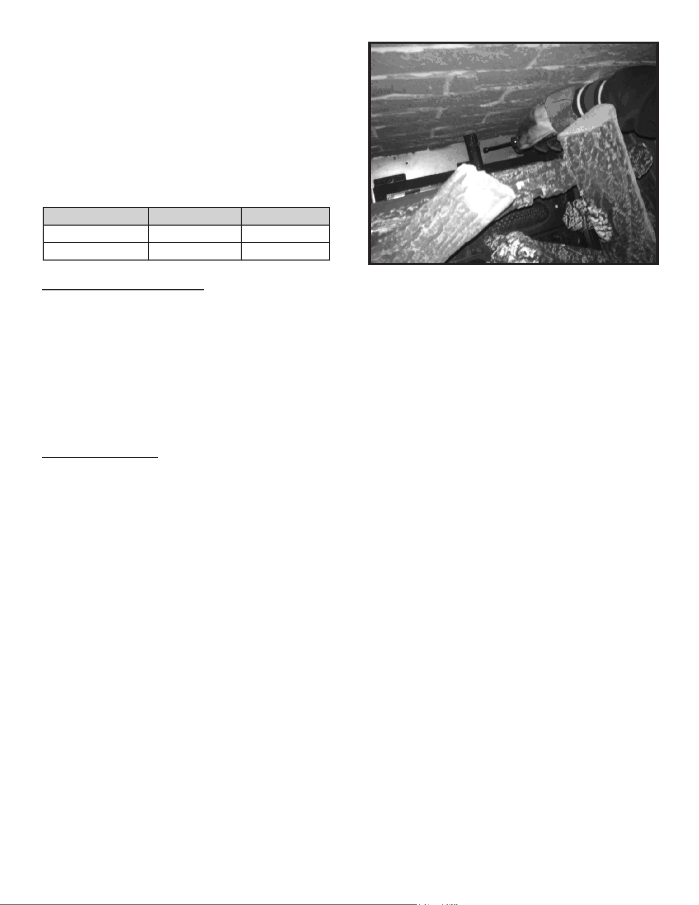
45
Majestic MARQ36IN-B, MARQ42IN-B Installation Manual • 2614-980 Rev. P • 5/22
E. Air Shutter Setting
Natural Gas (NG) installations:
As a general rule, it is acceptable to reduce the shutter
opening to adjust for vertical vent pipe sections prior to
the initial re up.
• Vertical Termination: May reduce shutter setting by 1/8 in.
• Horizontal Termination (more than 4 ft. vertical in vent
conguration): May reduce shutter setting by 1/8 in.
• Horizontal Termination (less than 4 ft vertical in vent
conguration): May reduce shutter setting by 1/16 in.
Propane installations
• It is recommended that the air shutter on propane
appliances remain at full open position.
Air Shutter Adjustment
Adjustment can be made to the air shutter with or without
the logs installed with a ¼ in. nut driver. See Figure 9.1.
Air shutter settings should be adjusted by a qualied ser-
vice technician at the time of installation. The air shutter
is pre-set at the factory for minimum vertical, maximum
horizontal vent run for this appliance: 2 ft. vertical and 7
in. horizontal (MARQ36IN-B) and 3 ft. vertical and 10 in.
horizontal (MARQ42IN-B).
Factory Pre-Set Air Shutter Settings
MODEL NG Propane
MARQ36IN-B 3/8 in. Full Open
MARQ42IN-B 3/4 in. 3/4 in.
To adjust air shutter:
• Loosen the screw on the burner assembly.
• To close the air shutter, turn shutter clockwise.
• To open air shutter, turn shutter counterclockwise.
• Tighten the screw.
NOTICE: Flames should not appear orange or stretch to
the top refractory. If sooting occurs, provide more air by
opening the air shutter.
Shutter Setting Verication / Flame Appearance
• After 15 minutes, the ames will be a yellow/blue mix.
The front ames may be blue at this time.
• After 30 minutes, the ames should be yellow with
some blue ames near the burner ports.
• After 1 hour, the ame will be at is maximum maturity.
Note: Visually, a propane ame may differ from a
natural gas ame. This is due to the different chemical
compositions that make up both fuel types. In general, the
Propane ames may be a little shorter and much brighter
than a natural gas ame.
Figure 9.1. Air Shutter Location
WARNING! Risk of Explosion or Delayed Ignition! Im-
properly adjusted air shutter could cause soot buildup.
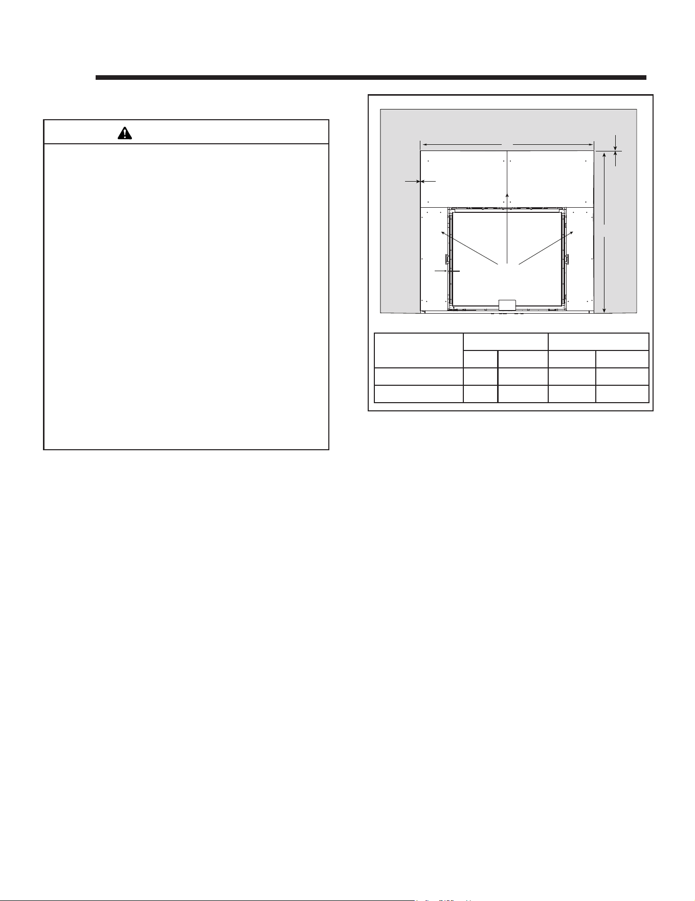
Majestic MARQ36IN-B, MARQ42IN-B Installation Manual • 2614-980 Rev. P • 5/2246
10 10
Finishing
Figure 10.1 Non-combustible Facing Diagram
0 in.
NON-COMBUSTIBLE
BOARD
A
B
COMBUSTIBLE MATERIAL
0 IN.
0 IN.
MODEL
A B
in. mm in. mm
MARQ36IN-B 61 1549 57-5/8 1464
MARQ42IN-B 67 1702 62-5/8 1591
A. Facing Material
NOTICE: Surface temperatures around the appliance will
become warm while the appliance is in operation. Ensure
finishing materials used for all surfaces (floor, walls,
mantels, etc.) will withstand temperatures up to 190°F. If
using vinyl ooring, refer to Section 3.E.
Risk of Fire!
DO NOT apply combustible materials beyond the min-
imum clearances. Comply with all minimum clearanc-
es to combustibles as specied in this manual. Ma-
terials overlapping into non-combustible zones could
ignite and will interfere with air ow through decorative
barrier fronts.
• Metal front of appliance may be covered with non-
combustible materials only.
• Facing and/or nishing materials must not interfere
with air ow through decorative barrier fronts, removal
of decorative barrier fronts or access for service.
• Facing and/or finishing materials must never
overhang into the glass opening.
• Observe all clearances when applying combustible
materials.
• Seal gaps between the nished wall and appliance
top and sides using a 300 ºF minimum sealant. Refer
to Figure 10.1.
WARNING
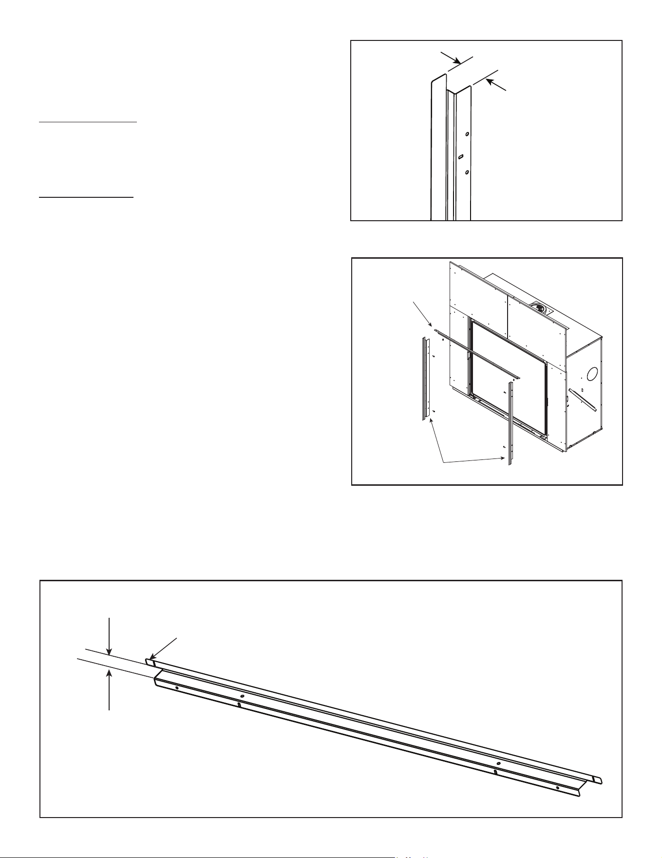
47
Majestic MARQ36IN-B, MARQ42IN-B Installation Manual • 2614-980 Rev. P • 5/22
Figure 10.3 Left and Right Side Finishing Template Bends
TOP FINISHING
TEMPLATE
SIDE FINISHING
TEMPLATES
Figure 10.4 Top and Side Finishing Template Locations
Figure 10.2 Top Finishing Template Bend
1-1/4 IN.
TAB
3/4 IN.
B. Finishing Templates
Two side nishing templates and one top nishing
template are supplied with the appliance. Refer to the
decorative barrier front instructions for template removal.
INSIDE FIT Method: The nishing template pieces are
required for installations that require more than one inch
thick nishing materials to be installed over the face of the
factory-supplied 1/2 inch non-combustible board. Refer
to section 10.D for more information.
OVERLAP Method: The supplied templates are not
required for nishing materials less than one inch thick.
The required decorative barrier front will overlap nish
materials less than one inch thick. Refer to section 10.D
for more information. Remove template by removing the
the two top screws and two screws on each side. The
glass assembly will need to be removed to access the side
screws. Follow the glass removal instructions in Section
11.
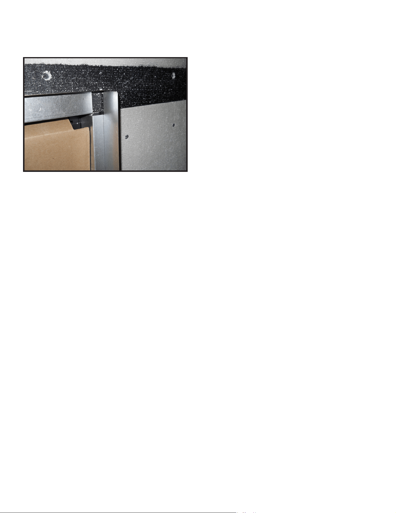
Majestic MARQ36IN-B, MARQ42IN-B Installation Manual • 2614-980 Rev. P • 5/2248
Note: A thin layer of mortar may be applied over the
visible non-combustible board between nishing material
and the replace opening.
Figure 10.5 Finishing Template Bends
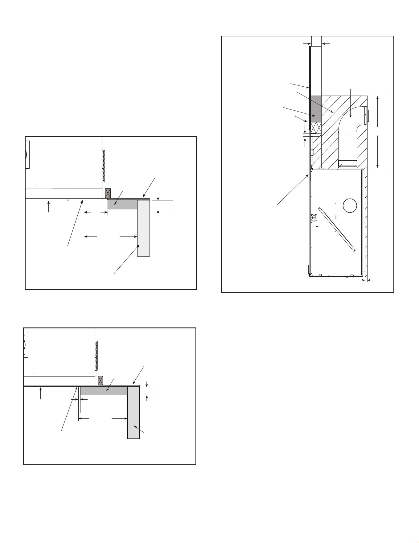
49
Majestic MARQ36IN-B, MARQ42IN-B Installation Manual • 2614-980 Rev. P • 5/22
C. Mantel and Wall Projections
WARNING! Risk of Fire! Comply with all minimum clear-
ances as specied. Framing closer than the minimums list-
ed must be constructed entirely of non-combustible materi-
als (i.e., steel studs, concrete board, etc.).
Combustible Mantel Legs or Wall Projections
Non-Combustible Mantel Legs or Wall Projections
FIREPLACE
OPENING
COMBUSTIBLE OR
NON-COMBUSTIBLE
WALL
14 IN. MIN.
NON-COMBUSTIBLE
COLUMN
10 IN. MAX.
1/2 IN. BUILDING MATERIAL
FACTORY-SUPPLIED
NON-COMBUSTIBLE
BOARD
SEE SECTION 10.D
FOR REQUIRED
CLEARANCES
7 IN.
MIN.
FIREPLACE
OPENING
COMBUSTIBLE OR
NON-COMBUSTIBLE WALL
14 IN. MIN.
COMBUSTIBLE
COLUMN
4 IN. MAX.
1/2 IN. BUILDING MATERIAL
FACTORY-SUPPLIED
NON-COMBUSTIBLE
BOARD
Figure 10.6 Combustible Mantel Leg and Wall Projections
Figure 10.7 Non-Combustible Mantel Leg and Wall Projections
Figure 10.8 Non-Combustible Zone
Non-Combustible Zone
When installing a mantel, provisions must be made
in order to secure the mantel to the adjacent framing
materials. For example, lintel brackets or lag bolts may
be considered for this purpose.
NO COMBUSTIBLES
IN HATCHED AREA
1/2 IN. BUILDING MATERIAL
(MAY BE COMBUSTIBLE)
FACTORY-SUPPLIED
1/2 IN.
NON-COMBUSTIBLE
BOARD
PIPE IS FOR VISUAL
REFERENCE ONLY
1 IN.
= COMBUSTIBLES
NOT ALLOWED
39 IN.
2 X 4 OR GREATER
FRAMING MATERIAL
NOTE:
2 X 4 HEADER
CONFIGURATION
2 X 4 ONLY IN
GRAY AREA
1/2 IN.
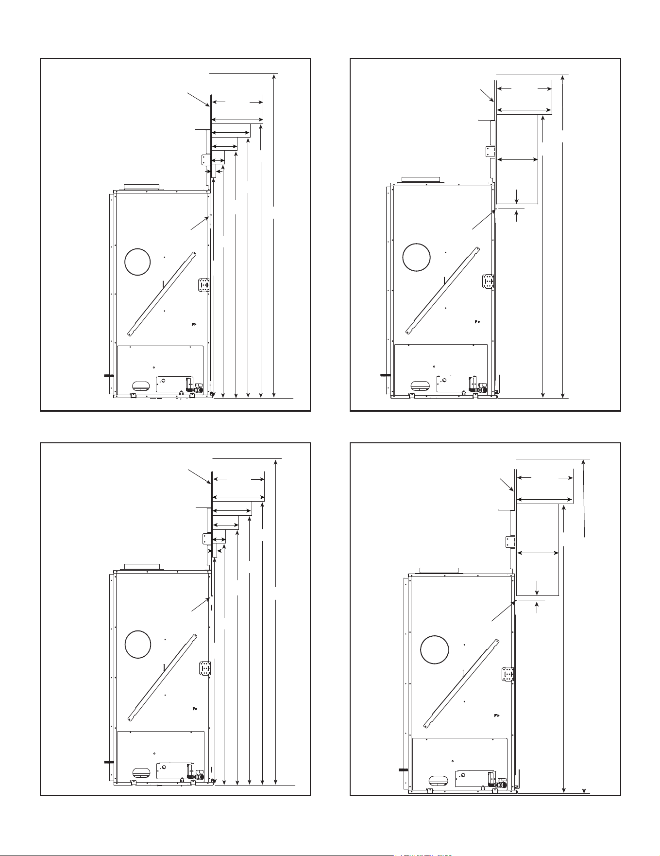
Majestic MARQ36IN-B, MARQ42IN-B Installation Manual • 2614-980 Rev. P • 5/2250
Figure 10.9 Combustible Mantel Allowance - MARQ36IN-B
Figure 10.10 Non-Combustible Mantel Allowance - MARQ36IN-B,
Non-Combustible Mantel ProjectionsCombustible Mantel Projections
1
46
3
6
12
9
49
52
55
58
FIREPLACE
OPENING
1/2 IN.
NON-COMBUSTIBLE
MATERIAL
MARQ36IN-B
MAX.
87-17/16
Measurement from
fireplace opening to
bottom of appliance:
= 35-3/16 IN. (MARQ36IN-B)
Ceiling
Note: All measurements in inches.
Note: Measurement is taken
from bottom of appliance.
Note:All measurements in inches.
Note: Measurement is taken
from bottom of appliance.
12
10
56
FIREPLACE
OPENING
1-1/4 IN.
1/2 IN.
NON-COMBUSTIBLE
MATERIAL
MARQ36IN-B
MAX.
87-13/16
Measurement from fireplace
opening to bottom of appliance:
= 35-3/16 IN. (MARQ36IN-B)
Ceiling
Figure 10.11 Combustible Mantel Allowance - MARQ42IN-B Figure 10.12 Non-Combustible Mantel Allowance - MARQ42IN-B
1
51
3
6
12
9
54
57
60
63
FIREPLACE
OPENING
1/2 IN.
NON-COMBUSTIBLE
MATERIAL
MARQ42IN-B
MAX.
92-13/16
Measurement from
fireplace opening to
bottom of appliance:
= 40-3/16 IN. (MARQ42IN-B)
Ceiling
Note: All measurements in inches.
Note: Measurement is taken
from bottom of appliance.
Note:All measurements in inches.
Note: Measurement is taken
from bottom of appliance.
12
10
61
FIREPLACE
OPENING
1-1/4 IN.
1/2 IN.
NON-COMBUSTIBLE
MATERIAL
MARQ42IN-B
MAX.
92-13/16
Measurement from fireplace
opening to bottom of appliance:
= 40-3/16 IN. (MARQ42IN-B)
Ceiling
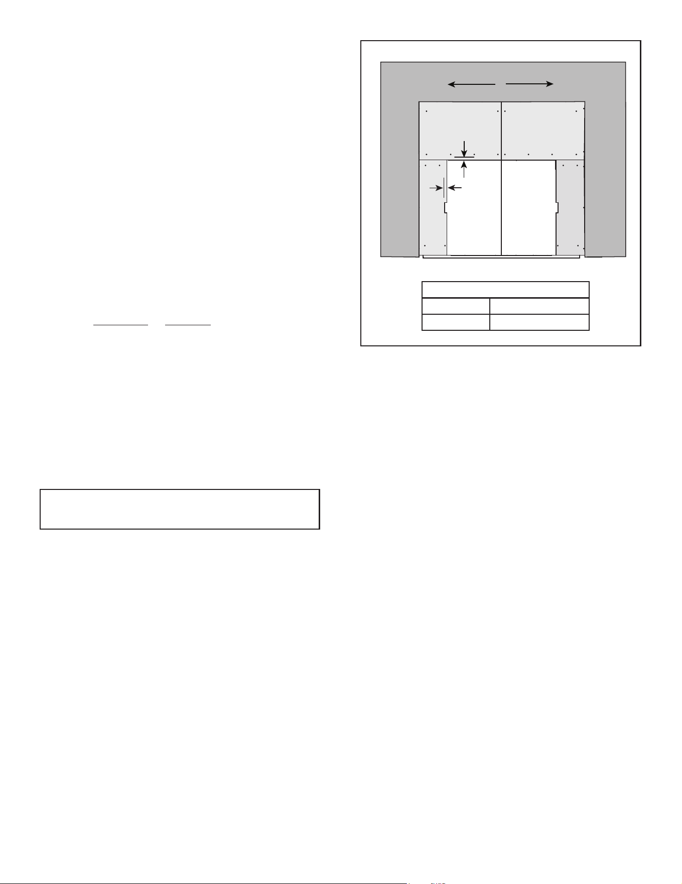
51
Majestic MARQ36IN-B, MARQ42IN-B Installation Manual • 2614-980 Rev. P • 5/22
D. Decorative Barrier Front Dimensions for
Finishing
A decorative barrier front is required for this appliance.
Only decorative barrier fronts certied for use with this
appliance model may be used. Contact your dealer for
a list of decorative barrier fronts that may be used. Once
you have determined what kind of decorative barrier front
and nishing material is going to be used on the replace,
you may use the table below which shows the decorative
barrier front models and the nishing material thickness
allowed. For an inside t there is an available template to
ensure that proper decorative barrier front clearances are
maintained with nishing material with thickness greater
than 1 inch.
A
B
COMBUSTIBLE MATERIAL
Figure 10.11 Inside Fit Decorative Barrier Fronts
The decorative barrier fronts approved for use with this
appliance have been designed to be installed by two
methods: Overlap Fit or Inside Fit. Before beginning the
installation, it is important to determine with method will
be used.
Overlap Fit Method: These decorative barrier fronts
have been designed to be installed over nishing mate-
rial up to one inch thick.
Inside Fit Method: These decorative barrier fronts may
be recessed into non-combustible nishing material up to
10 inches thick.
NOTICE: Proper clearances from the replace opening
to any nishing material thicker than 1 inch MUST be
maintained.
NOTE: Finishing templates are included with this product.
See Section 10.B.
DIMENSIONS
A 3/4 IN.
B 1-1/4 IN.
Approved Decorative Barrier Fronts: FSMQ36,
FSMQ42
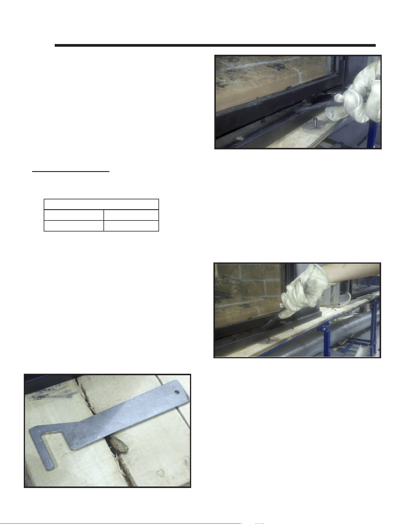
Majestic MARQ36IN-B, MARQ42IN-B Installation Manual • 2614-980 Rev. P • 5/2252
11 11
Appliance Setup
A. Fixed Glass Assembly
WARNING! Risk of Asphyxiation! Handle xed glass
assembly with care. Inspect the gasket to ensure it is
undamaged and inspect the glass for cracks, chips or
scratches.
• DO NOT strike, slam or scratch glass.
• DO NOT operate replace with glass removed, cracked,
broken or scratched.
• Replace as a complete assembly.
CAUTION! Risk of Injury! Glass assembly installation
and removal must be performed by a qualied service
technician. See chart below for glass assembly weights.
• MARQ42IN-B MODELS: It is recommended that
Glass installation and removal be performed by two
qualied service technicians.
Figure 11.2. Glass Clip Tool Location
Figure 11.3. Inserting Glass Clip Tool
Figure 11.1. Glass Clip Tool
CAUTION! Risk of Cuts or Abrasions. Wear protective
gloves and safety glasses during installation. Sheet metal
edges are sharp.
Removing Fixed Glass Assembly
This xed glass assembly is held in place by lower glass
clips, side clips and top retaining rail. To remove clips, en-
gage the spring clips with the tool and pull tool out slightly.
1. The glass clip removal/installation tool is fastened to
the lower right corner of the appliance. Remove tool
by removing one screw. See Figure 11.1. If glass clip
removal tool becomes misplaced, a cotter pin removal
tool may be used.
2. To disengage bottom glass clips, position the glass
clip removal/installation tool parallel to the oor and
insert it about two inches into the gap between the
glass frame and the front bottom replace lip. Insert
the tool on the lower left side of the glass clip and
move to the right to engage the clip. Using one mo-
tion, pull out slightly while pushing down to disengage
bottom glass clip. Repeat for the other bottom spring
clips. There are three on the MARQ36IN-B and four
on the MARQ42IN-B. See Figure 11.2 and Figure
11.3.
3. Disengage the left and right glass clips one at a time
using the glass clip removal/installation tool. Insert
tool from the top side of the side glass clip. Pull the
glass tool out slightly to disengage the side clip. See
Figure 11.7.
4. Grasp the left and right sides of the glass assembly
and carefully pull outward to remove the bottom from
the support tabs on the bottom glass clips. Lower the
glass to remove it from the top retainer rail.
NOTICE: Protect and prevent the hearth from damage by
covering it with a drop cloth.
Glass Weights
MARQ36IN-B MARQ42IN-B
32 lbs 41 lbs
CAUTION! Risk of Injury! DO NOT put ngers under
glass frame. Fingers may get pinched by glass frame
during removal.
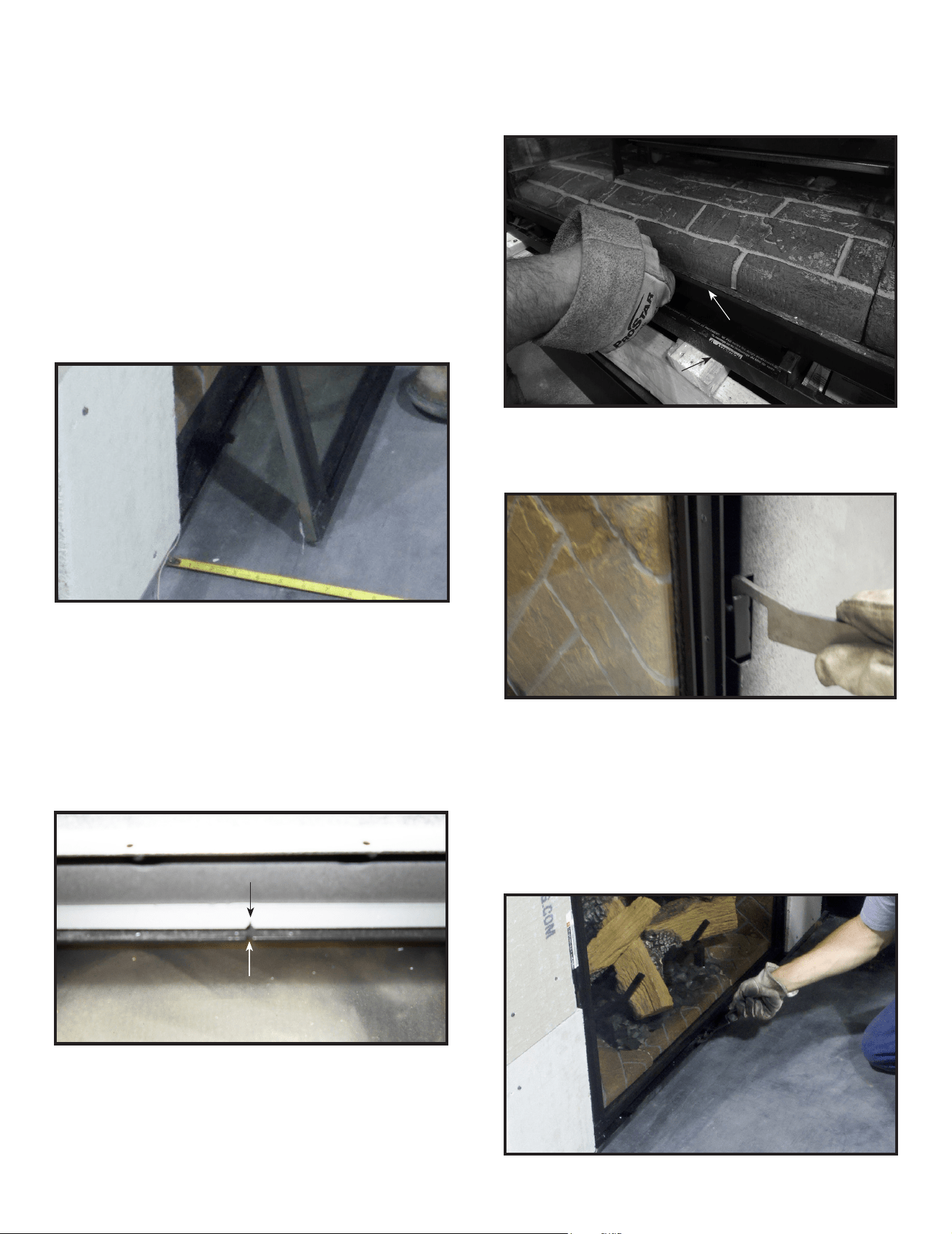
53
Majestic MARQ36IN-B, MARQ42IN-B Installation Manual • 2614-980 Rev. P • 5/22
GRASP FRAME BY LIP THAT GRASP FRAME BY LIP THAT
PROJECTS FROM GLASS. DO NOT PROJECTS FROM GLASS. DO NOT
INSERT FINGERS UNDER RAIL.INSERT FINGERS UNDER RAIL.
RAILRAIL
LIPLIP
TOP RETAINING RAIL NOTCHTOP RETAINING RAIL NOTCH
GLASS FRAME NOTCHGLASS FRAME NOTCH
Figure 11.4 Positioning Glass
Figure 11.6. Installing Glass
Replacing Fixed Glass Assembly
This xed glass assembly is held in place by two side
clips, one top retaining rail and lower glass clips. The
MARQ36IN-B has three lower glass clips and the
MARQ42IN-B has four lower glass clips. To remove
clips, engage the spring clips with the tool and pull tool
out slightly. Rotate wrist left and right to disengage clip.
The glass clip tool is shown in Figure 11.1.
1. Tool is fastened to the lower right corner of the re-
place. Remove tool by removing one screw. If glass
clip removal tool becomes misplaced, a cotter pin re-
moval tool may be used.
2. Position the xed glass assembly so that it is about
eight inches from the face of the appliance. See Fig-
ure 11.4.
3. Center the xed glass assembly from left to right in-
side the top of the appliance opening.
The glass frame has tabs on the bottom that coincide
with the bottom glass clip location. The MARQ36IN-B
has three tabs and the MARQ42IN-B has four tabs. If
the glass is not centered, it cannot be installed proper-
ly. Align the notch at the top center of the glass frame
assembly with the notch on the top retaining rail. See
Figure 11.5.
Figure 11.5 Align Notches
Figure 11.7. Securing Side Glass Clips
4. Install xed glass assembly by lifting it up and sliding
it into the top retaining rail. Grasp the xed glass as-
sembly on the sides.
CAUTION! Risk of Injury! DO NOT put ngers under
glass frame. Fingers may get pinched by glass frame
during installation.
6. Once the left and right glass clips are installed, en-
gage the bottom clips by inserting the glass clip tool at
a sharp downward angle to get between the gap be-
tween the glass frame and the front bottom replace
lip. See Figure 11.8.
7. Return glass tool to its shipping location in the low-
er right corner of the appliance and secure with one
screw.
5. Ensure the xed glass assembly is situated tight
against the rebox face. Engage the left and right
glass clips using the glass clip tool. See Figure 11.7.
Figure 11.8. Securing Bottom Glass Clips
Once the glass is installed tightly into the top retainer
rail, push in the bottom so that the glass assembly
rests on the support tabs on the glass clip. See Fig-
ure 11.6.
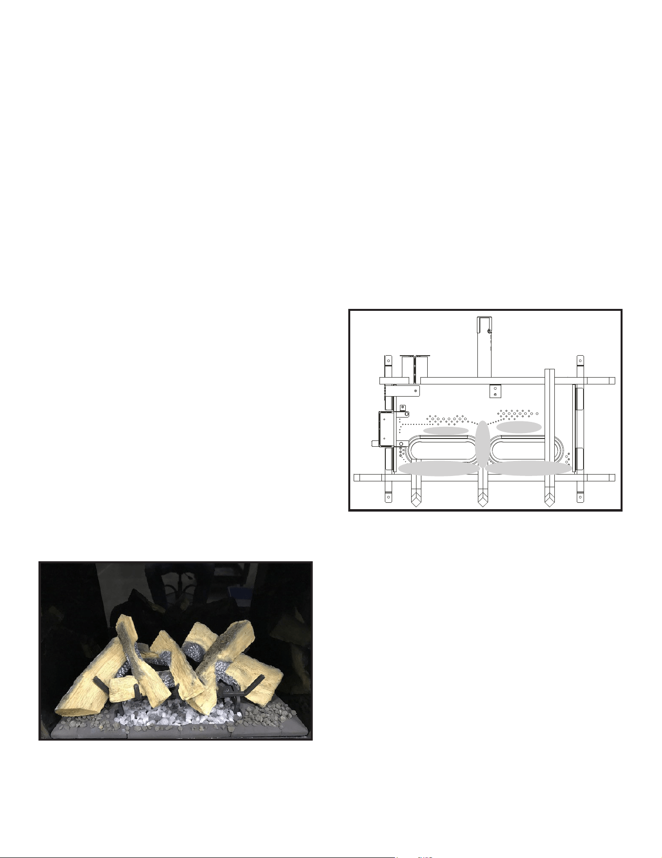
Majestic MARQ36IN-B, MARQ42IN-B Installation Manual • 2614-980 Rev. P • 5/2254
B. Remove the Shipping Materials
Remove shipping materials from inside or underneath
the rebox.
• The splatter guard is a piece of corrugated material
used to protect the appliance during the installation
process before nishing work on the whole hearth is
complete. Splatter guards may be factory installed
or accompany the decorative barrier front of the
unit, depending on the replace model. Splatter
guards must be removed before appliance is red.
WARNING! Risk of Fire! Close the ball valve before in-
stalling the splatter guard to prevent accidental lighting.
Remove the splatter guard before lighting the appliance.
D. Refractory
WARNING! Refractory is REQUIRED to be installed in
appliance. Operating the appliance without refractory is
not safe.
Refractory set is required in product. Refractory kit is
shipped separately with instructions. Follow directions
supplied in kit for proper installation.
C. Clean the Appliance
Clean/vacuum any sawdust that may have accumulated
inside the rebox or underneath in the control cavity.
E. Lava Rock Placement
1. Apply the lava rock as shown in Figure 11.9. The lava
is to be placed around the base hearth refractory and
can be used to conceal the joints of the hearth base
refractory pieces.
Figure 11.9. Apply Lava Rock
Figure 11.10. Location of Glowing Embers in Shaded Areas
F. Glowing Ember Placement
WARNING! Risk of Explosion! Follow ember placement
instructions in manual. DO NOT place embers directly over
burner ports. Replace ember material annually. Improperly
placed embers interfere with proper burner operation.
Ember material is shipped with this gas appliance. To place
the ember material:
• Embers CANNOT be placed directly over ports. Care
should be taken not to cover the lighting trail of ports
(from back to front).
• Place dime-size pieces of Glowing Embers® just in front
of the port trail, but not on or in between the ports (see
Figure 11.10). Care should be taken so that the ports are
not covered. Failure to follow this procedure will likely
cause lighting and sooting problems.
• Save the remaining ember materials for use during
appliance servicing. The embers provided should be
enough for 3 to 5 applications.
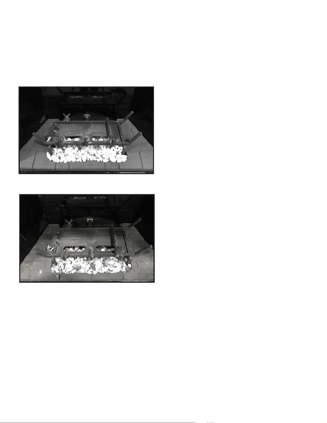
55
Majestic MARQ36IN-B, MARQ42IN-B Installation Manual • 2614-980 Rev. P • 5/22
G. Teco-Sil Placement
Teco-Sil is shipped with the appliance. To place Teco-Sil:
• Locate and open the bag of Teco-Sil.
• Spread Teco-Sil evenly over bottom glass assembly.
See Figure 11.11
• Turn ember lights on and fog Teco-Sil to desired
coverage. See Figure 11.12.
Figure 11.11. Teco-Sil Placement
Figure 11.12. Teco-Sil Fogged
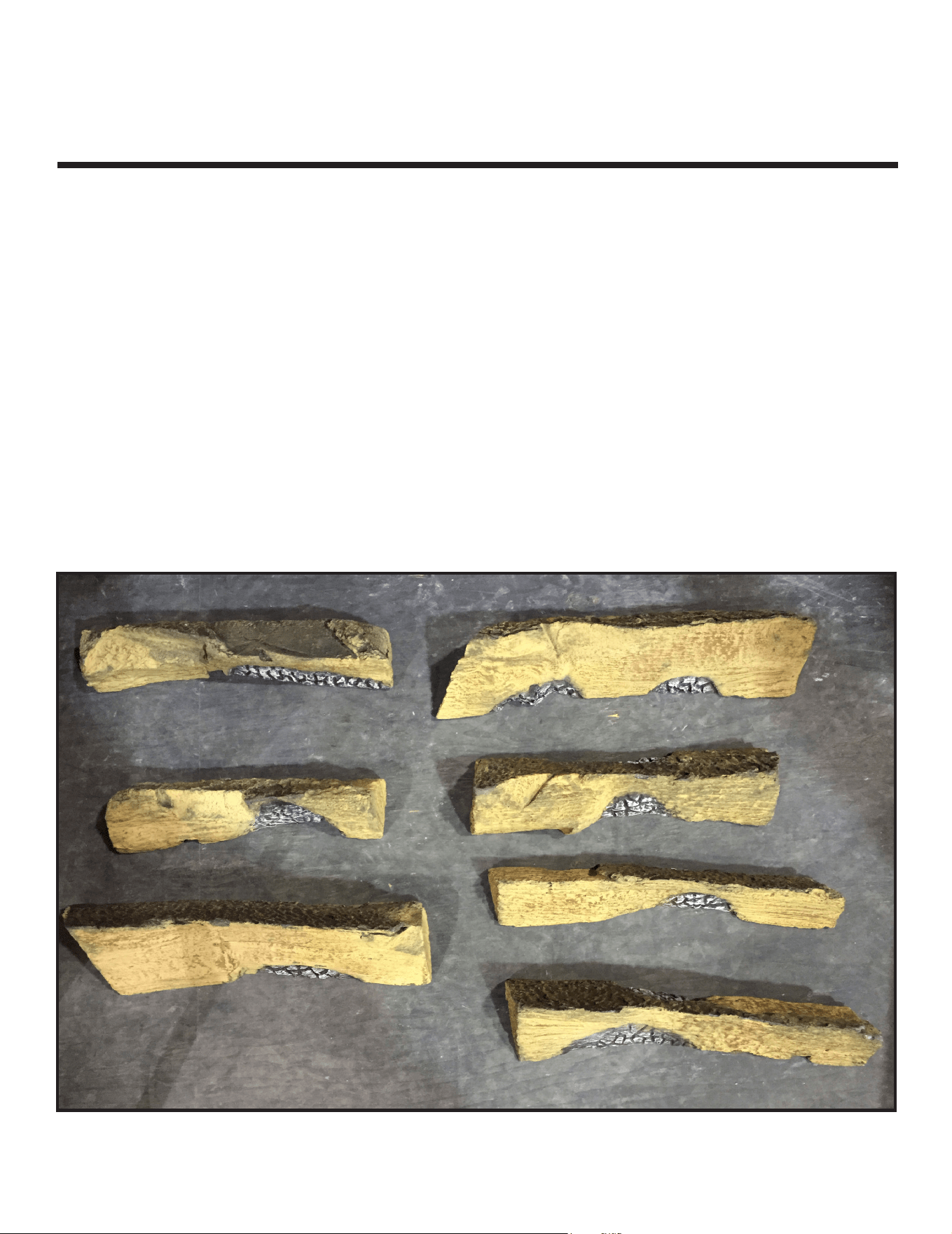
Majestic MARQ36IN-B, MARQ42IN-B Installation Manual • 2614-980 Rev. P • 5/2256
Log Set Assembly: LOGSMQ36
Models: MARQ36IN, MARQ36IN-B
LOG PLACEMENT INSTRUCTIONS
H. Log Set Assembly
Figure 1. Log Set
22
Log Set:
Log #1 - SRV2270-701 (01)
Log #2 - SRV2270-703 (03)
Log #3 - SRV2270-702 (02)
Log #4 - SRV2270-704 (04)
CAUTION: Logs are fragile! Carefully remove the logs from the packaging.
11
33
44
55
66
77
Log #5 - SRV2270-706 (06)
Log #6 - SRV2271-705 (15)
Log #7 - SRV2271-707 (17)
Logs can be identied by the number molded into the bottom of the log.
The numbers are listed in parentheses above.
NOTE: Interior of MARQ36IN is shown in log installation pictures. Instructions apply to
both the MARQ36IN and MARQ36IN-B.
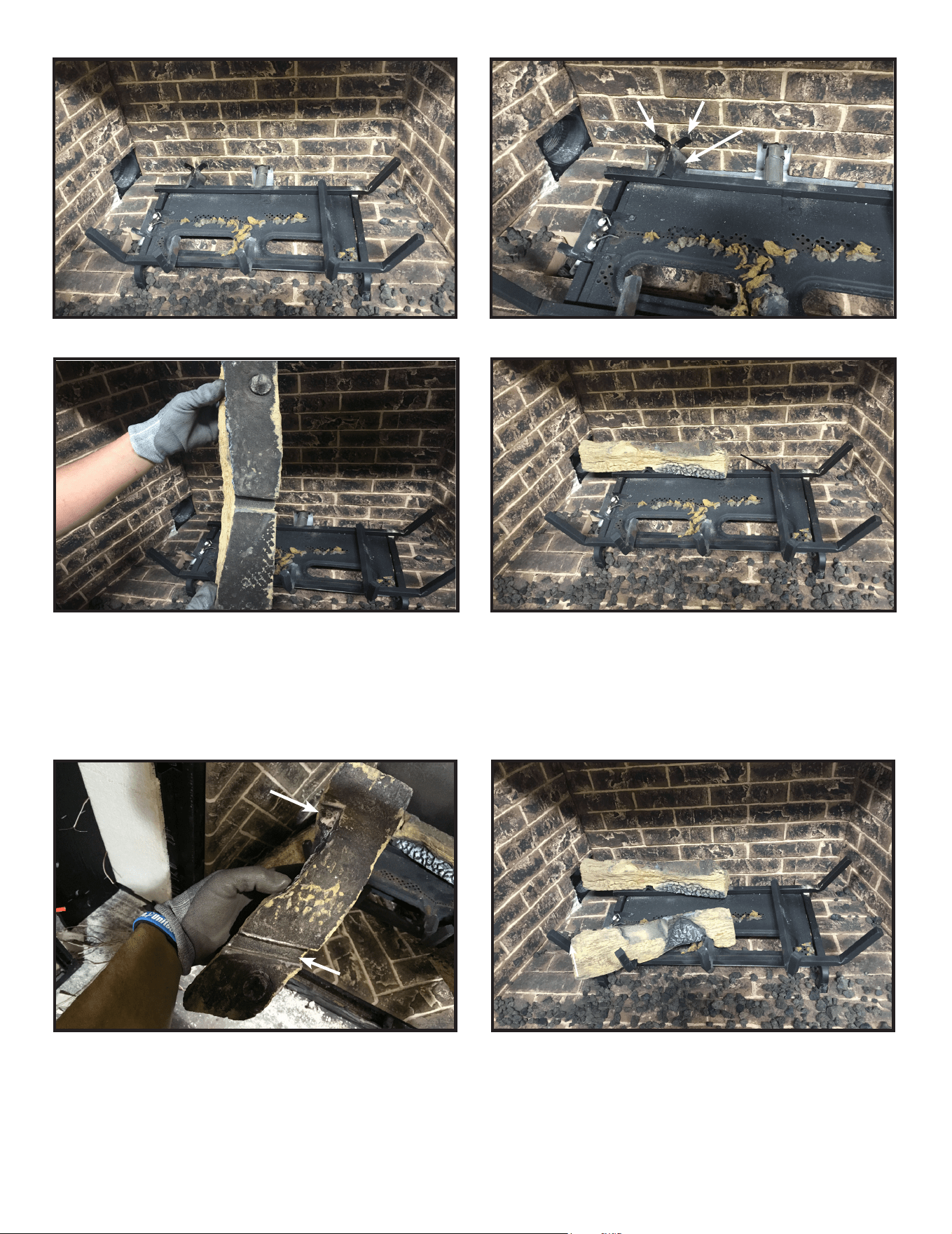
57
Majestic MARQ36IN-B, MARQ42IN-B Installation Manual • 2614-980 Rev. P • 5/22
CAUTION: Logs are fragile, handle with care. Log #1 (SRV2270-701): Log tab shown in Figure 3 is engaged with groove
in bottom of log shown in Figure 4. Attached to the grate assembly on back left corner and position on rear cross member
of grate assembly. Be sure that the log is pushed back against the two vertical tabs for proper placement. See Figure 5.
Figure 4.
Figure 2.
Figure 3.
Figure 5.
Figure 6.
LOG PLACEMENT SLOTSLOG PLACEMENT SLOTS
22
Figure 7.
Log #2 (SRV2270-703): Log #2 is positioned on the front left grate using groove depicted in Figure 5. Ensure the log is slid
forward to bend in grate tine. The log also mates with the center grate tine using feature shown in Figure 5.
11
11
22
11
22
VERTICAL TABSVERTICAL TABS
LOG TABLOG TAB
FEATUREFEATURE
GROOVEGROOVE
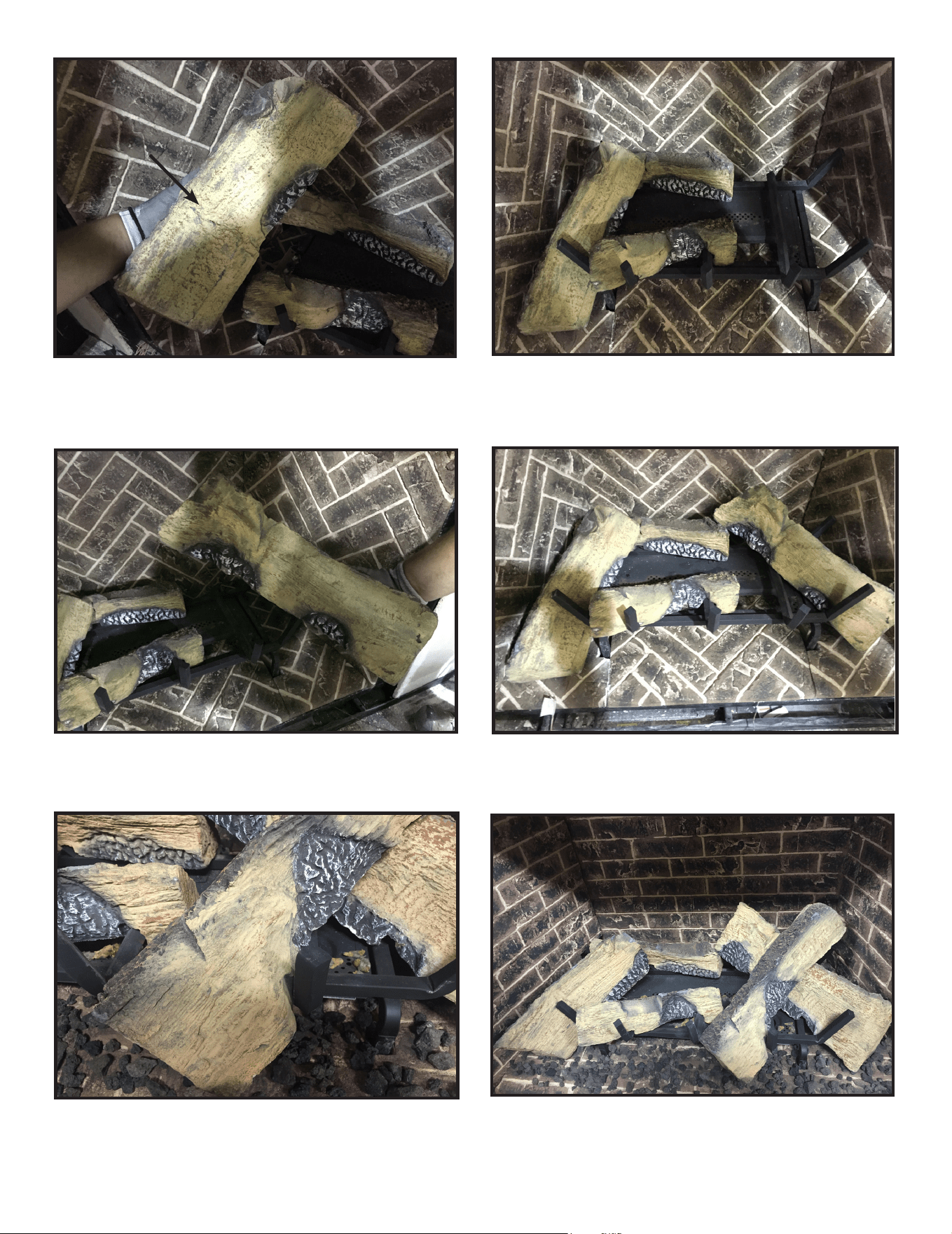
Majestic MARQ36IN-B, MARQ42IN-B Installation Manual • 2614-980 Rev. P • 5/2258
Log #3 (SRV2270-702): Log #3 is positioned on the base refractory, slid tight to the far left grate tine shown in Figure 9,
resting on the recess in Log #1 and the pilot shield. See Figure 9.
Figure 9.
Figure 10.
Figure 12.
Figure 13.
Figure 8.
Figure 11.
Log #4 (SRV2270-704): See Log #4 in Figure 10. Position Log #4 between grate tine and rebox wall. Rest the end of Log
#4 on the at area on Log #1 and pivot the log forward until it contacts the grate tine. See Figure 11.
Log #5 (SRV2270-706) : Position Log #5 on top of the center grate tine and interlock with the right front grate tine, mating
with the recess on Log #4. See Figure 12 & 13.
33
11
33
22
44
44
11
22
33
55
33
11
44
55
22
VERTICAL VERTICAL
GROOVEGROOVE
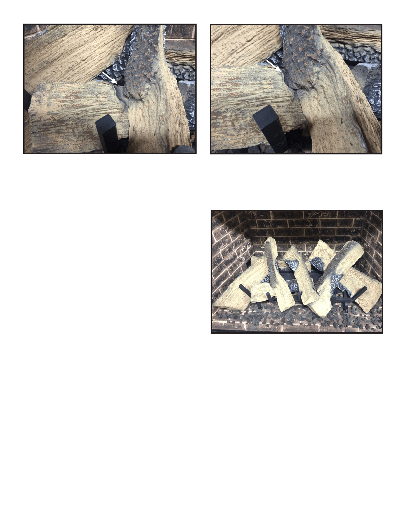
59
Majestic MARQ36IN-B, MARQ42IN-B Installation Manual • 2614-980 Rev. P • 5/22
Figure 14.
Figure 15.
Figure 16. Log Set Installed
Log #6 (SRV2271-705): Position Log #6 onto at spots on Log #2 and Log #3. The locking feature in Log #6 will mate with
the cleft in Log #2. See Figures 14 & 15.
Log #7 (SRV2271-707): Position Log #7 in the center of the
rebox, mating with recesses in Log #1 and Log #5. Log #7
will rest on the top of Log #2 and mate with the middle grate
tine. See Figure 16.
66
66
33
22
66
11
77
44
55
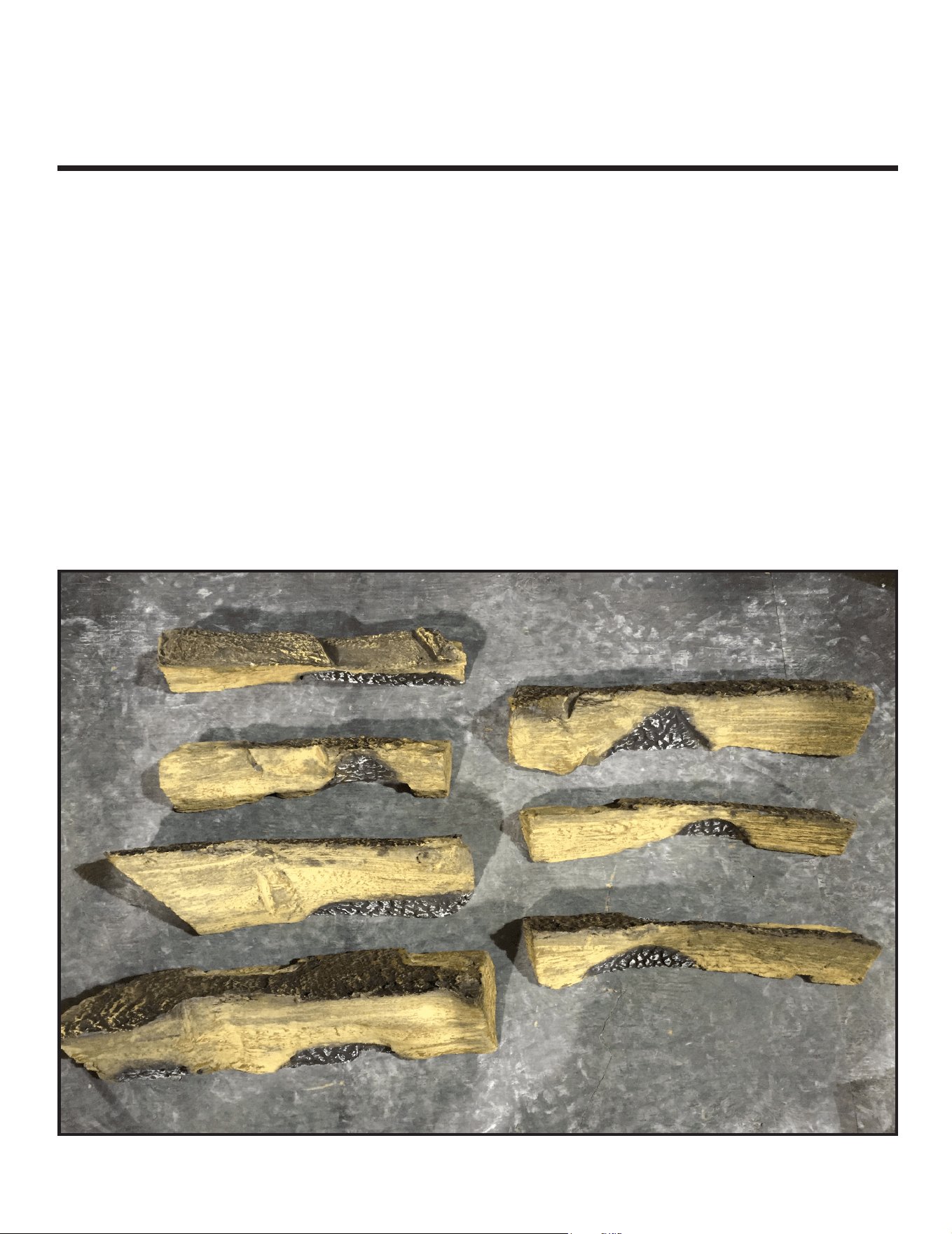
Majestic MARQ36IN-B, MARQ42IN-B Installation Manual • 2614-980 Rev. P • 5/2260
Log Set Assembly: LOGSMQ42
Models: MARQ42IN, MARQ42IN-B
LOG PLACEMENT INSTRUCTIONS
Figure 1. Log Set
22
Log Set:
Log #1 - SRV2271-701 (11)
Log #2 - SRV2271-703 (13)
Log #3 - SRV2271-702 (12)
Log #4 - SRV2271-704 (14)
CAUTION: Logs are fragile! Carefully remove the logs from the packaging.
11
33
44
55
66
77
Log #5 - SRV2271-706 (16)
Log #6 - SRV2271-705 (15)
Log #7 - SRV2271-707 (17)
Logs can be identied by the number molded into the bottom of the log.
The numbers are listed in parentheses above.
NOTE: Interior of MARQ42IN is shown in log installation pictures. Instructions apply to
both the MARQ42IN and MARQ42IN-B.
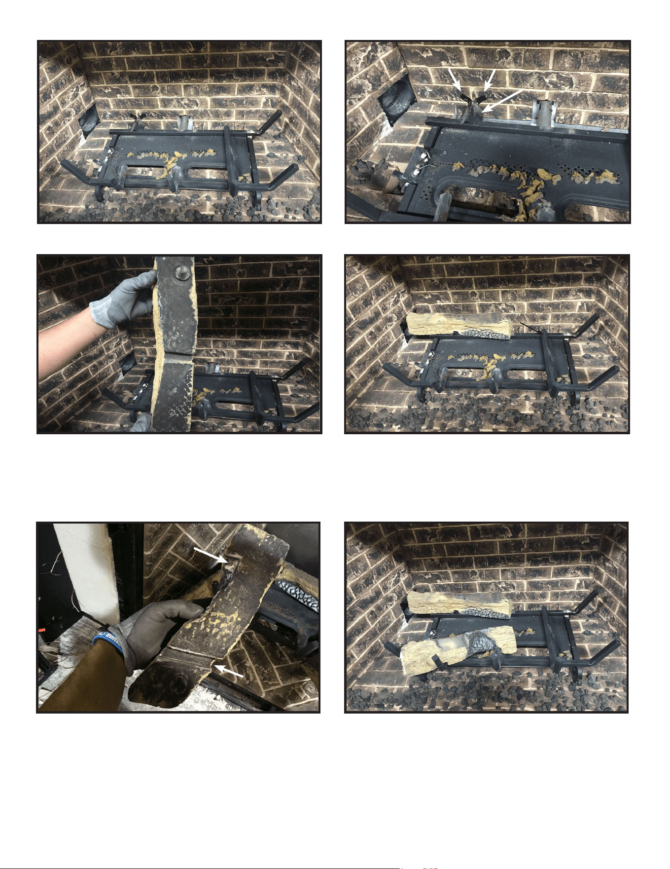
61
Majestic MARQ36IN-B, MARQ42IN-B Installation Manual • 2614-980 Rev. P • 5/22
CAUTION: Logs are fragile, handle with care. Log #1 (SRV2271-701): Log tab shown in Figure 3 engage with the groove
in the bottom of log shown in Figure 4. Attach to grate assembly on back left corner and rest on rear cross member of grate
assembly. Be sure that the log is pushed back against two vertical tabs for proper placement. See Figure 5.
Figure 4.
Figure 2.
Figure 3.
Figure 5.
Figure 5.
LOG PLACEMENT SLOTSLOG PLACEMENT SLOTS
22
Figure 6.
Log #2 (SRV2271-703): Position Log #2 on the front left grate using groove shown in Figure 5. Ensure the log is slid forward
to bend in the grate tine. The log will also mate with the center grate tine using feature shown in Figure 5.
11
11
22
22
11
VERTICAL TABSVERTICAL TABS
LOG TABLOG TAB
FEATUREFEATURE
GROOVEGROOVE
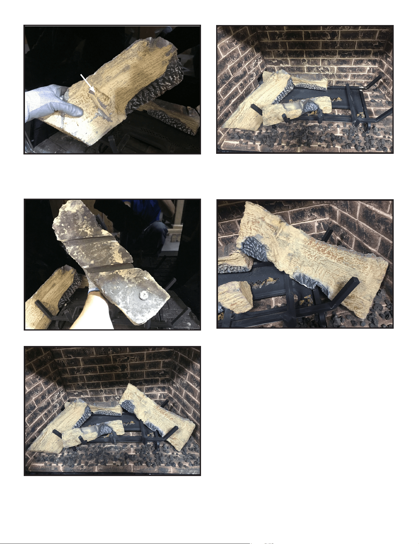
Majestic MARQ36IN-B, MARQ42IN-B Installation Manual • 2614-980 Rev. P • 5/2262
Log #3 (SRV2271-702): Position Log #3 on the base refractory. Mate log with the far left grate tine, into the vertical groove
shown in Figure 8. Log #3 will rest on recess in Log #1 and the pilot shield. See Figure 9.
Figure 9.
Figure 10.
Figure 12.
Figure 8.
Figure 11.
Log #4 (SRV2271-704): See bottom of Log #4 in Figure 10. The two grooves will mate with the grate tines as shown in
Figure 11. The log will contact the base refractory, side refractory panel, and the tip of Log #1, creating 5 total contact points.
11
33
22
33
22
11
44
44
44
33
VERTICAL GROOVEVERTICAL GROOVE
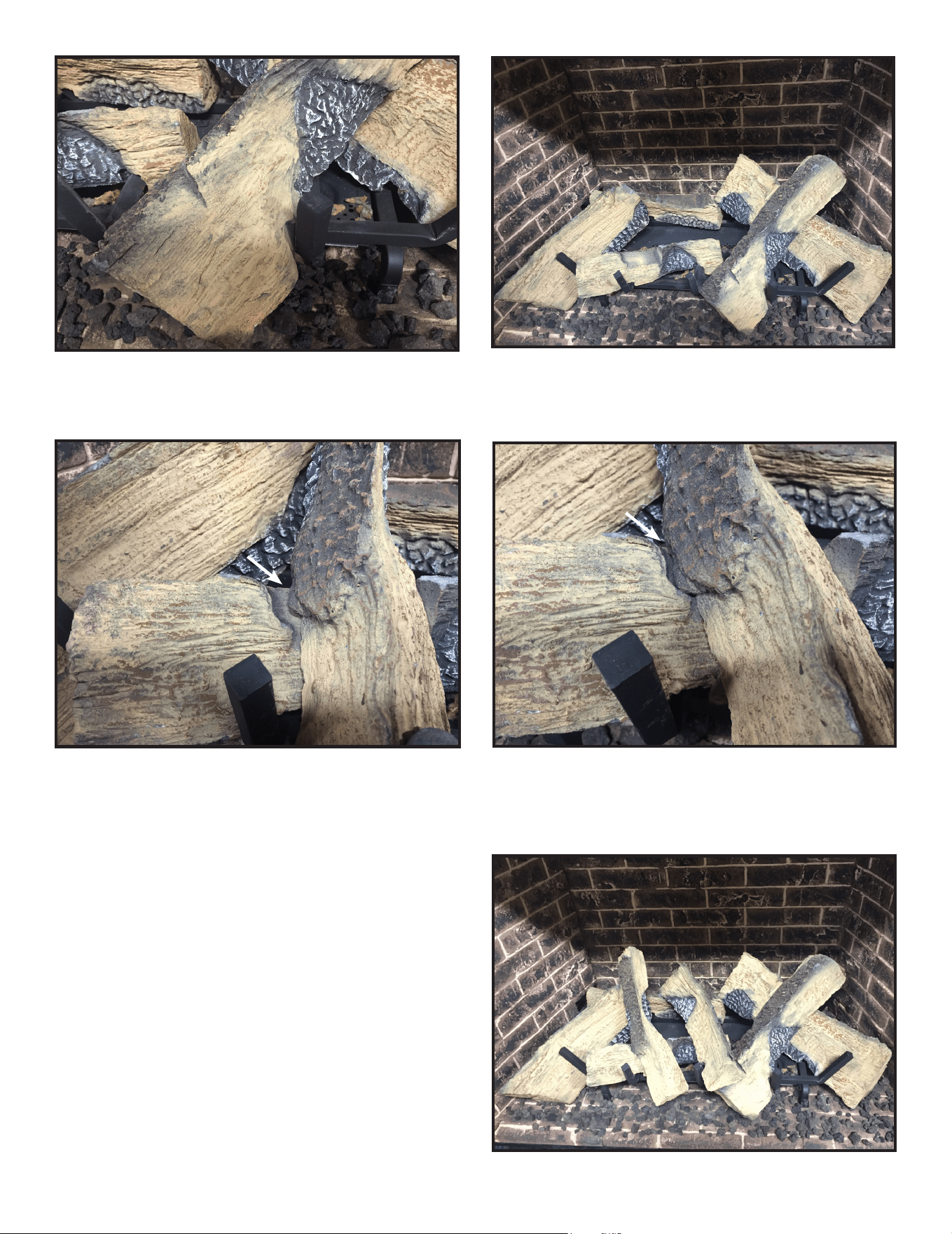
63
Majestic MARQ36IN-B, MARQ42IN-B Installation Manual • 2614-980 Rev. P • 5/22
Figure 13.
Figure 14.
Figure 15.
Figure 17. Log Set Installed.
Figure 16.
Log #5 (SRV2271-706): Position Log #5 on top of the center grate tine and interlock with the right front grate tine, mating
with the recess on Log #4. See Figure 13 & 14.
Log #7 (SRV2271-707): Position Log #7 in the center of
the rebox, mating with recesses in Log #1 and Log #5. Log
#7 will rest on top of Log #2 and mate with middle grate.
See Figure 17.
55
33
11
22
55
44
66
66
33
22
66
77
11
55
44
Log #6 (SRV2271-705): Positon Log #6 onto at spots on Logs #2 and Log #3. The locking feature in Log #6 will mate
with the cleft in Log #2 as shown in Figures 15 &16.
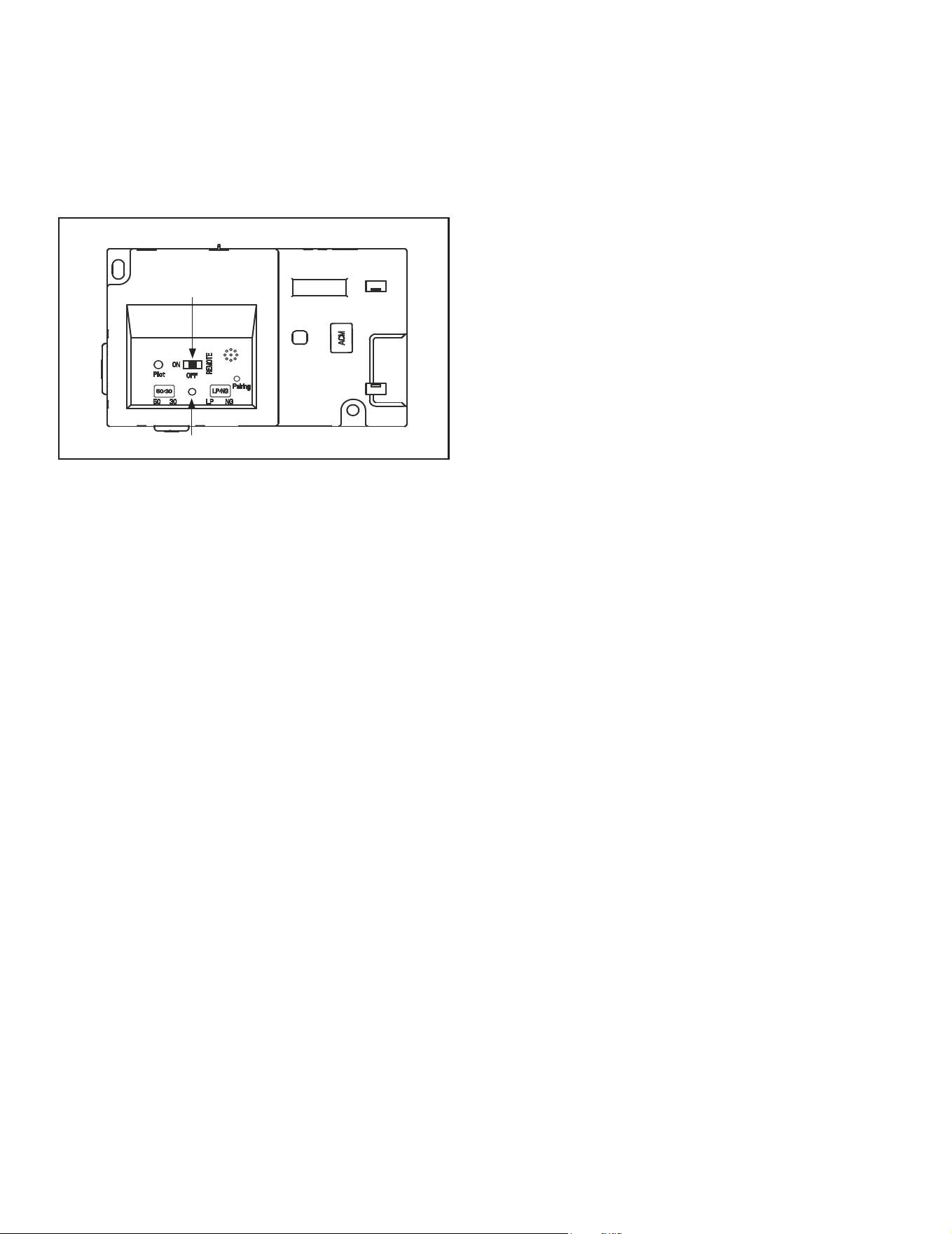
Majestic MARQ36IN-B, MARQ42IN-B Installation Manual • 2614-980 Rev. P • 5/2264
J. LED’s
LED’s are factory installed. No additional set up or acti-
vation required.
• See Owner’s Manual for maintenance and bulb
replacement.
K. Install Decorative Barrier Front
WARNING! Risk of Fire! Install ONLY decorative barrier
fronts approved by Hearth & Home Technologies. Unap-
proved decorative barrier fronts may cause replace to
overheat.
This fireplace has been supplied with an integral
barrier to prevent direct contact with the xed glass
panel. DO NOT operate the replace with the barrier
removed.
Contact your dealer or Hearth & Home Technologies if
the barrier is not present or help is needed to properly
install one.
For more information refer to the instructions supplied with
your decorative barrier front.
I. IntelliFire Touch Control System Setup
• Detailed instructions for electrical wiring and connec-
tions are provided in Section 8.
• Verify that the 3-Position switch on the IFT-ECM is
switched to the REMOTE position. Detailed Operat-
ing Instructions for the IFT-ECM are provided in Sec-
tion 3.J of the Owner’s Manual.
Figure 11.5 IFT-ECM
This appliance is factory-equipped with an IntelliFire
Touch
remote control. The remote was paired to the re-
place and tested at the factory. It does not need to be
paired again, unless an accessory kit will be added at
the time of installation. If no additional accessory will be
added, simply follow steps one through seven below.
1. If installed, remove batteries from remote.
2. Verify that the new appliance has power and secure
electrical connections.
3. Adjust the ECM selector switch to ‘REMOTE’ mode.
4. Wait to verify LED indicator on the ECM stops ash-
ing.
5. Install batteries in the RC400 remote.
6. The RC400 remote will automatically pair to the appli-
ance as pre-set at the factory.
3 POSITION SWITCH
TOP VIEW
LED INDICATOR
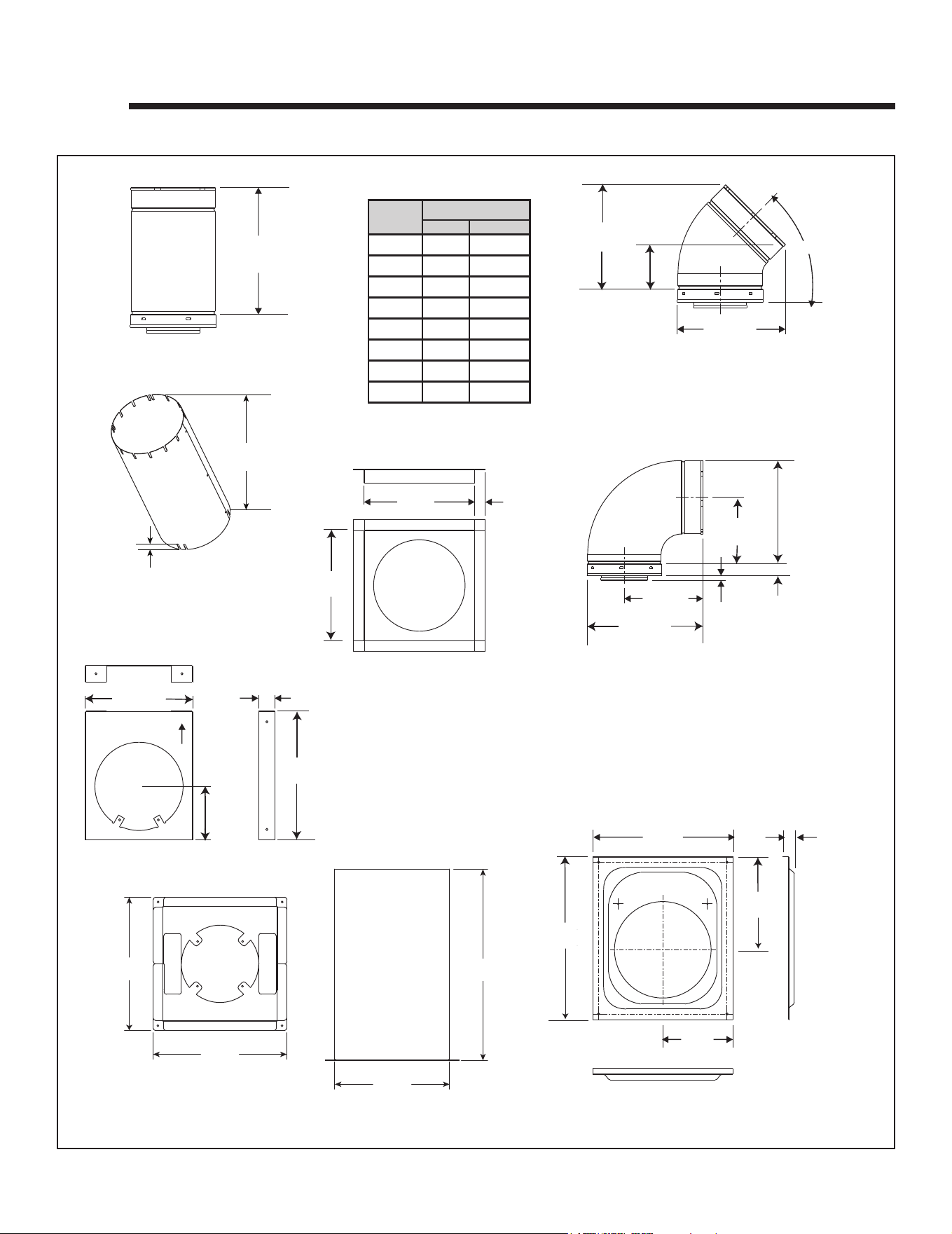
65
Majestic MARQ36IN-B, MARQ42IN-B Installation Manual • 2614-980 Rev. P • 5/22
12 12
Reference Materials
A. Vent Components Diagrams
Figure 12.1 DVP vent components
10-1/2 in.
(267 mm)
10-7/8 in.
(276 mm)
45
°
7-3/8 in.
(187 mm)
11-3/8 in.
(289 mm)
1-1/4 in. (32 mm)
9-1/4 in.
(235 mm)
13-1/4 in.
(337 mm)
1/2 in.
TYP
DVP90ST (90° Elbow)
10 in.
(254 mm)
10 in.
(254 mm)
1 in.
(25 mm)
DVP-FS (Ceiling Firestop)
DVP45 (45º Elbow)
DVP Pipe (see chart)
Effective
Height/Length
4-7/8 in.
(124 mm)
(13 mm)
10 in.
(254 mm)
1- 1/2 in.
(38 mm)
5 in.
(127 mm)
12 in.
(305 mm)
UP
DVP-HVS (Vent Support)
12 in.
(305 mm)
14 in.
(356 mm)
1 in.
(25 mm)
8 in.
(203 mm)
6 in.
(152 mm)
DVP-WS (Wall Shield Firestop)
Finished Height: 19-3/4 in./502 mm
UNIV-AS2 (Attic Insulation Shield)
Tab=1 in.
(25.4 mm)
20-3/4 in.
(527 mm)
14 IN.
(356 MM)
14 IN.
(356 MM)
20 IN.
(508 MM)
12 IN.
(305 MM)
DVP-RDS
ROOF DECK INSULATION SHIELD
Pipe
Effective Length
Inches Millimeters
DVP4 4 102
DVP6 6 152
DVP12 12 305
DVP24 24 610
DVP36 36 914
DVP48 48 1219
DVP6A 3 to 6 76 to 152
DVP12A 3 to 12 76 to 305
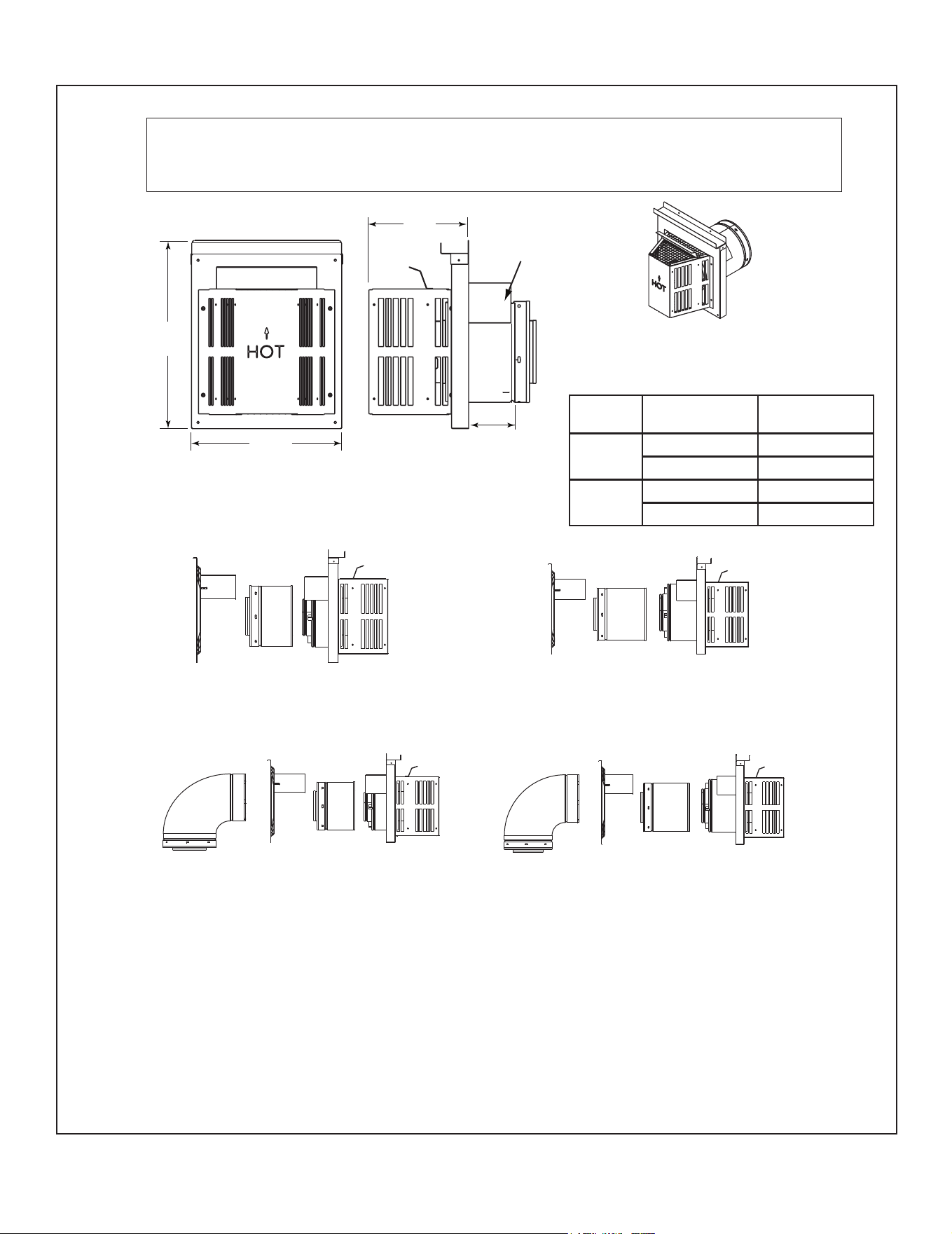
Majestic MARQ36IN-B, MARQ42IN-B Installation Manual • 2614-980 Rev. P • 5/2266
DVP-TRAP1
DVP-TRAP2
DVP-TRAPK2
DVP-TRAPK1
DVP-TRAP
Horizontal Termination Cap
15-1/8 in.
(384 mm)
12 in.
(305 mm)
8 in.
(203 mm)
Max
Effective
Length
Note: Heat shields MUST overlap by a minimum of 1-1/2 in. (38 mm). The heat shield is designed to be
used on a wall 4 in. to 7-1/4 in. (102 mm to 184 mm) thick. If wall thickness is less than 4 in. (102 mm) the
existing heat shields must be field trimmed. If wall thickness is greater than 7-1/4 in. (184 mm) a DVP-HSM-B
will be required.
Heat
Shield
A. Vent Components Diagrams (continued)
Figure 12.2 DVP vent components
Term Cap
Minimum
Effective Length
Maximum
Effective Length
Trap1
3-1/8 in. 4-5/8 in.
79 mm 117 mm
Trap2
5-3/8 in. 9-3/8 in.
137 mm 238 mm
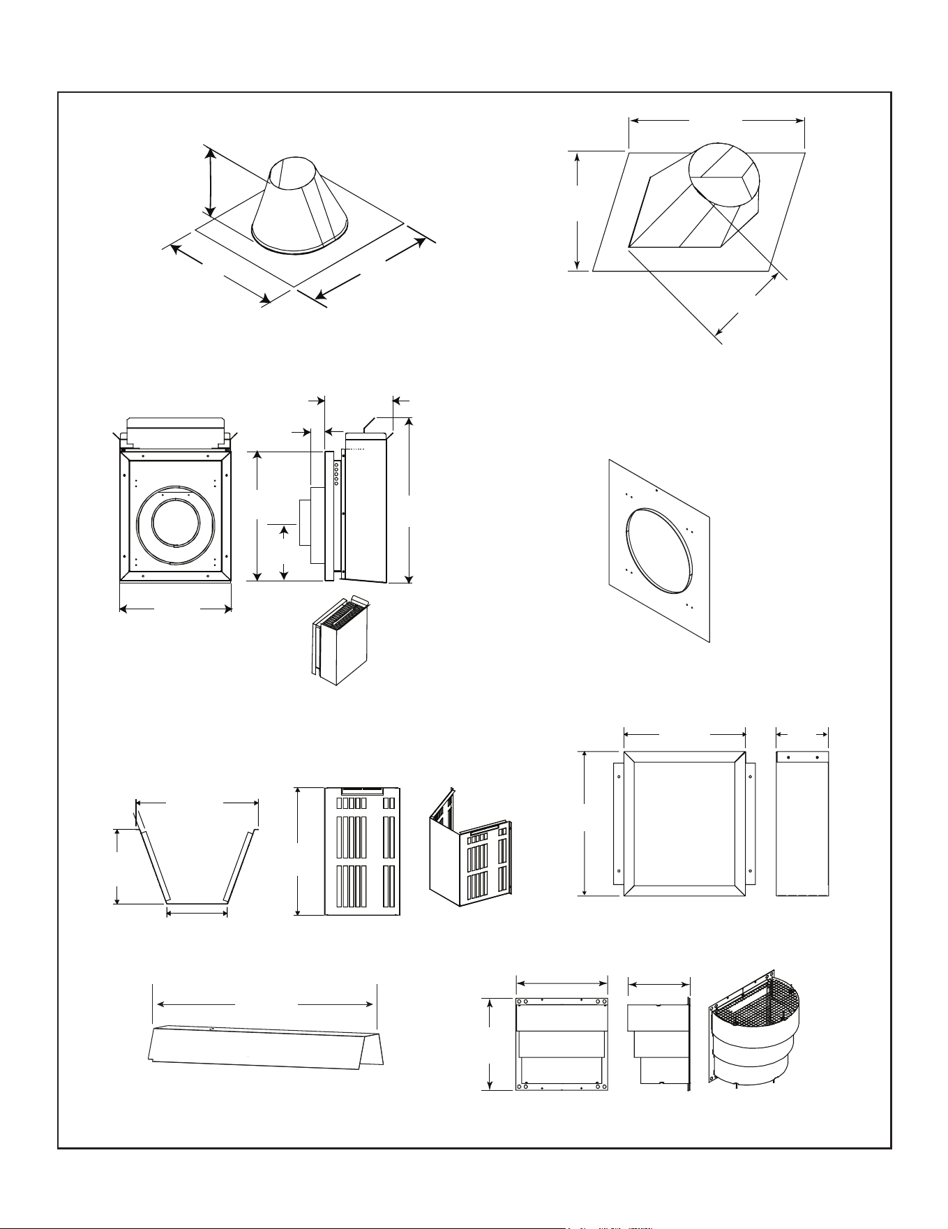
67
Majestic MARQ36IN-B, MARQ42IN-B Installation Manual • 2614-980 Rev. P • 5/22
13-1/4 in.
(337 mm)
24-5/8 in.
(625 mm)
27-1/2 in.
(699 mm)
RF6M
Roof Flashing Multi-pak
31 in.
(787 mm)
24-5/8 in.
(625 mm)
13-1/4 in.
(337 mm)
RF12M
Roof Flashing Multi-pak
Cap Shield
DRC-RADIUS
13-7/8 in.
(352 mm)
9-1/2 in.
(241 mm)
14 in.
(356 mm)
COOL-ADDM
Cap Shield
11-5/8 in.
(295 mm)
5-3/4 in.
(146 mm)
7-1/8 in.
(181 mm)
12-1/8 in.
(308 mm)
DVP-BEK2
DVP-HPC Cap Brick Extension
13-7/8 in.
(352 mm)
5 in.
(127 mm)
11-7/8 in.
(302 mm)
DVP-TRAPFL
Flashing
26 in.
660 mm
DVP-HSM-B
Extended Heat Shield
DVP-TB1
Basement Vent Cap
12 in.
(305 mm)
1-1/2 in.
(38 mm)
7-3/8 in.
(187 mm)
14 in.
(356 mm)
17-3/4 in.
(451 mm)
6 in.
152 mm
WARNING! Risk of Fire! DO NOT install DVP-TB1 in
application where vinyl siding is present.
A. Vent Components Diagrams (continued)
Figure 12.3 DVP Vent Components
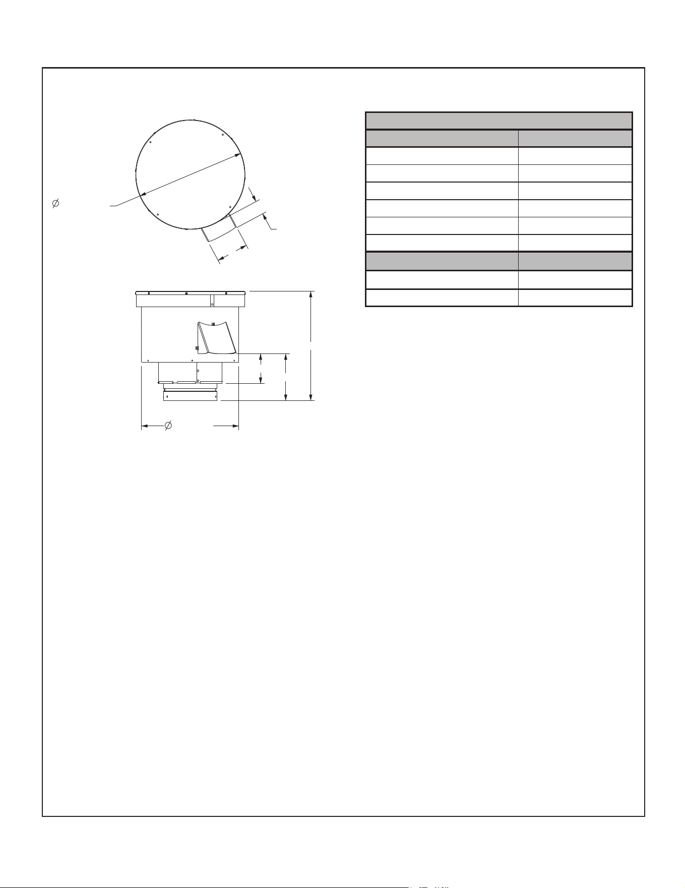
Majestic MARQ36IN-B, MARQ42IN-B Installation Manual • 2614-980 Rev. P • 5/2268
Figure 12.4 PVV-SLP Vent Components
13-5/8 IN.
13-11/16 IN.
1-3/4 IN.
4 IN.
5-7/8 IN.
3-11/16 IN.
12-1/8 IN.
TOP VIEW
SIDE VIEW
Required Wire Harness and PVV-SLEEVE
Lengths Available Part Number
10 ft. PV Wire Harness PVI-WH10
20 ft. PV Wire Harness PVI-WH20
40 ft. PV Wire Harness PVI-WH40
60 ft. PV Wire Harness PVI-WH60
80 ft. PV Wire Harness PVI-WH80
100 ft. PV Wire Harness PVI-WH100
Description Part Number
12 in. Wire Harness Sleeve PVV-SLEEVE-12
48 in. Wire Harness Sleeve PVV-SLEEVE-48
A. Vent Components Diagrams (continued)
PVV-SLP
Vertical Power Vent
Note: A wire harness is required to power the PVV-SLP and connect it to the appliance. It is ordered separately from
the PVV-SLP. Contact your dealer to order.
Note: The PVV-SLEEVE-12 and/or PVV-SLEEVE-48 is required to be installed with the PVV-SLP. It is ordered
separately from the PVV-SLP. Contact your dealer to order.
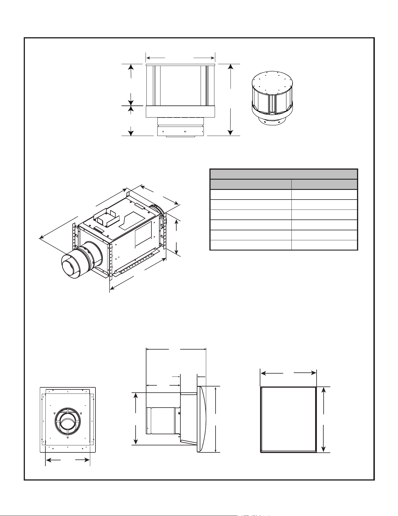
69
Majestic MARQ36IN-B, MARQ42IN-B Installation Manual • 2614-980 Rev. P • 5/22
A. Vent Components Diagrams (continued)
Figure 12.5 DVP vent components
7-1/4 in.
12 in.
305 mm
(184 mm)
5-1/4 in.
(133 mm)
12-1/2 in.
(318 mm)
DVP-TVHW
VerticalTermination Cap (Highwind)
Optional Wire Harness
DESCRIPTION PART NUMBER
10 ft. PV Wire Harness PVI-WH10
20 ft. PV Wire Harness PVI-WH20
40 ft. PV Wire Harness PVI-WH40
60 ft. PV Wire Harness PVI-WH60
80 ft. PV Wire Harness PVI-WH80
100 ft. PV Wire Harness PVI-WH100
PVI-SLP-B
Power Vent Inline
SLP-LPC
SLP Low Prole Cap
Note: Wire harnesses required to power the PVI-SLP-B
connect to the appliance and are ordered separately from
PVI-SLP-B. Contact your dealer to order.
16 IN.
406 mm
15 IN.
(381 mm)
16-11/16 IN.
(424 mm)
9-3/16 IN.
(233 mm)
4-1/2 IN.
114 mm
16-11/16 IN.
424 mm
13-5/8 IN.
(346 mm)
12-1/2 IN.
(318 mm)
12-1/2 IN.
318 mm
20-3/4 IN.
527 mm
13-5/8 IN.
346 mm
EFFECTIVE LENGTH
32 IN. (813 mm) MIN.
35 IN. (889 mm) MAX.
Note: The PVI-SLP-B requires one of the following op-
tions to be installed on this appliance.
Option A: IFT-RC400 OR
Option B: IFT-RC150, IFT-ACM
These accessories are purchased separately from the
PVI-SLP-B. Contact your dealer to order.
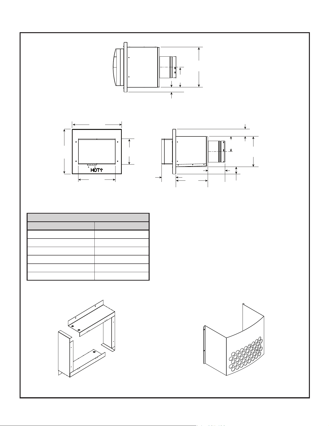
Majestic MARQ36IN-B, MARQ42IN-B Installation Manual • 2614-980 Rev. P • 5/2270
A. Vent Components Diagrams (continued)
Required Wire Harness
DESCRIPTION PART NUMBER
10 FT PV Wire Harness PVI-WH10
20 FT PV Wire Harness PVI-WH20
40 FT PV Wire Harness PVI-WH40
60 FT PV Wire Harness PVI-WH60
80 FT PV Wire Harness PVI-WH80
100 FT PV Wire Harness PVI-WH100
Note: Wire harnesses required to power the PVLP-SLP
connect to the appliance and are ordered separately from
PVLP-SLP. Contact your dealer to order.
Figure 12.6 PVLP-SLP Vent Components
PVLP-HS
Heat Shield
14 IN.
356 mm
15-1/2 IN.
394 mm
11-1/2 IN.
292 mm
8 IN.
203 mm
4-3/8 IN.
112 mm
10 IN.
254 mm
5-1/4 IN.
135 mm
2-1/4 IN.
57 mm
9-1/2 IN.
241 mm
4-3/4 IN.
121 mm
2-1/4 IN.
57 mm
1-1/2 IN.
38 mm
6-1/4 IN.
159 mm
Front View
Top View
Side View
Note: A PVLP-HS heat shield is available and sold
separately. Use if the PVLP-SLP is installed in a high trafc
area.
PVLP-BEK
Brick Kit
PVLP-SLP
Power Vent Low Prole
Note: The PVLP-SLP requires one of the following options to
be installed on this appliance.
Option A: IFT-RC400 or Option B: IFT-RC150, IFT-ACM.
These accessories are purchased separately from the PVLP-
SLP. Contact your dealer to order.

71
Majestic MARQ36IN-B, MARQ42IN-B Installation Manual • 2614-980 Rev. P • 5/22
Remote Controls, Wall Controls and Wall
Switches
Follow the instructions supplied with the control installed
to operate your replace:
For safety:
• Install a switch lock or a wall/remote control with child
protection lockout feature.
• Keep remote controls out of reach of children.
See your dealer if you have questions.
Printed in U.S.A. - Copyright 2022
Majestic, a brand of Hearth & Home Technologies
7571 215
th
Street West, Lakeville, MN 55044
www.majesticproducts.com
Please contact your Majestic dealer with any questions or concerns.
For the location of your nearest Majestic dealer,
please visit www.majesticproducts.com.
B. Accessories
Install approved accessories per instructions included
with accessories. Contact your dealer for a list of ap-
proved accessories.
WARNING! Risk of Fire and Electric Shock! Use ONLY
Hearth & Home Technologies-approved optional acces-
sories with this appliance. Using non-listed accessories
could result in a safety hazard and will void the warranty.
Optional Heat Management Kits
Follow the instruction supplied with the kit for operation.
• Preparation of the appliance for installing a heat
management kit is discussed in Section 5.E.
See your dealer if you have questions.