OWNER’S / INSTALLATION MANUAL
MODEL #: NOVA48-CLR
NOVA CLEAR
®
AC 120 V 60 Hz 1200 W (4100 BTU’s)
AC 240 V 60 Hz 2400 W (8200 BTU’s)
07-00214
5023705
Read and understand this entire owner’s manual, including all safety information,
before plugging in or using this product. Failure to do so could result in fire, electric
shock, or serious personal injury.
Keep this owner’s manual for future reference. If you sell or give this product away,
make sure this manual accompanies this product.
AFFIX SERIAL NUMBER LABEL HERE
FOR FUTURE REFERENCE
IMPORTANT SAFETY INFORMATION!
i)
ii)
iii)
iv)
IMPORTANT SAFETY INFORMATION!
This device complies with part 15 of the FCC Rules.
Operation is subject to the following two conditions:
(1) This device may not cause harmful interference, and
(2) this device must accept any interference received, including interference that may cause
undesired operation.
Note: This equipment has been tested and found to comply with the limits for a Class B digital
device, pursuant to Part 15 of the FCC Rules. These limits are designed to provide reasonable
protection against harmful interference in a residential installation. This equipment generates,
uses and can radiate radio frequency energy and, if not installed and used in accordance with
the instructions, may cause harmful interference to radio communications.
However, there is no guarantee that interference will not occur in a particular installation. If this
equipment does cause harmful interference to radio or television reception, which can be
determined by turning the equipment off and on, the user is encouraged to try to correct the
interference by one or more of the following measures:
Reorient or relocate the receiving antenna.
Increase the separation between the equipment and receiver.
Connect the equipment into an outlet on a circuit different from that to which the receiver is connected.
Consult the dealer or an experienced radio/TV technician for help.
Warning: Changes or modifications to this unit not expressly approved by the part responsible for
compliance could void the user’s authority to operate the equipment.
For Fireplaces:
FCC Radiation Exposure Statement
The device has been evaluated to meet general RF exposure requirement.
The device can be used in mobile(min20cm) exposure condition.
For Remote:
FCC Radiation Exposure Statement
The device has been evaluated to meet general RF exposure requirement.
The device can be used in portable exposure condition without restriction.
FCC COMPLIANCE STATEMENT

4
www.modernflames.com
Table of Contents
PREPARATION
.............................................................................................................................................................................. 5
PARTS AND HARDWARE
................................................................................................................................................................ 5
DIMENSIONS AND SPECIFICATIONS
................................................................................................................................................ 6
GLASS REMOVAL/INSTALLATION
................................................................................................................................................... 7
SIDE GLASS INSTALLATION
........................................................................................................................................................... 8
INSTALLATION STYLES
.................................................................................................................................................................. 9
BUILT-IN INSTALLATION FRAMING
............................................................................................................................................10-11
BUILT-IN INSTALLATION
......................................................................................................................................................... 12-13
HARDWIRING INSTALLATION
.................................................................................................................................................. 14-15
HEATER CONFIGURATION
...................................................................................................................................................... 16-17
LIT LOG AND CRUSHED GLASS INSTALLATION
............................................................................................................................. 18
SOUND MODES
.......................................................................................................................................................................... 19
LOG LIGHTING
........................................................................................................................................................................... 19
OPERATION
............................................................................................................................................................................... 20
CARE, CLEANING AND MAINTENANCE
.......................................................................................................................................... 34
REPLACEMENT PARTS LIST
......................................................................................................................................................... 35
OPERATION: TOUCH CONTROL PANEL
............................................................................................................................... 21
OPERATION: REMOTE CONTROL
.................................................................................................................................. 22-23
OPERATION: ON SCREEN CONTROLS
........................................................................................................................... 24-29
OPERATION: SMART PHONE APP
........................................................................................................................................ 30
OPERATION: STREAMING DEVICES
................................................................................................................................ 31-32
OPERATION: IMPORTANT WARNINGS
.................................................................................................................................. 33
Preparation
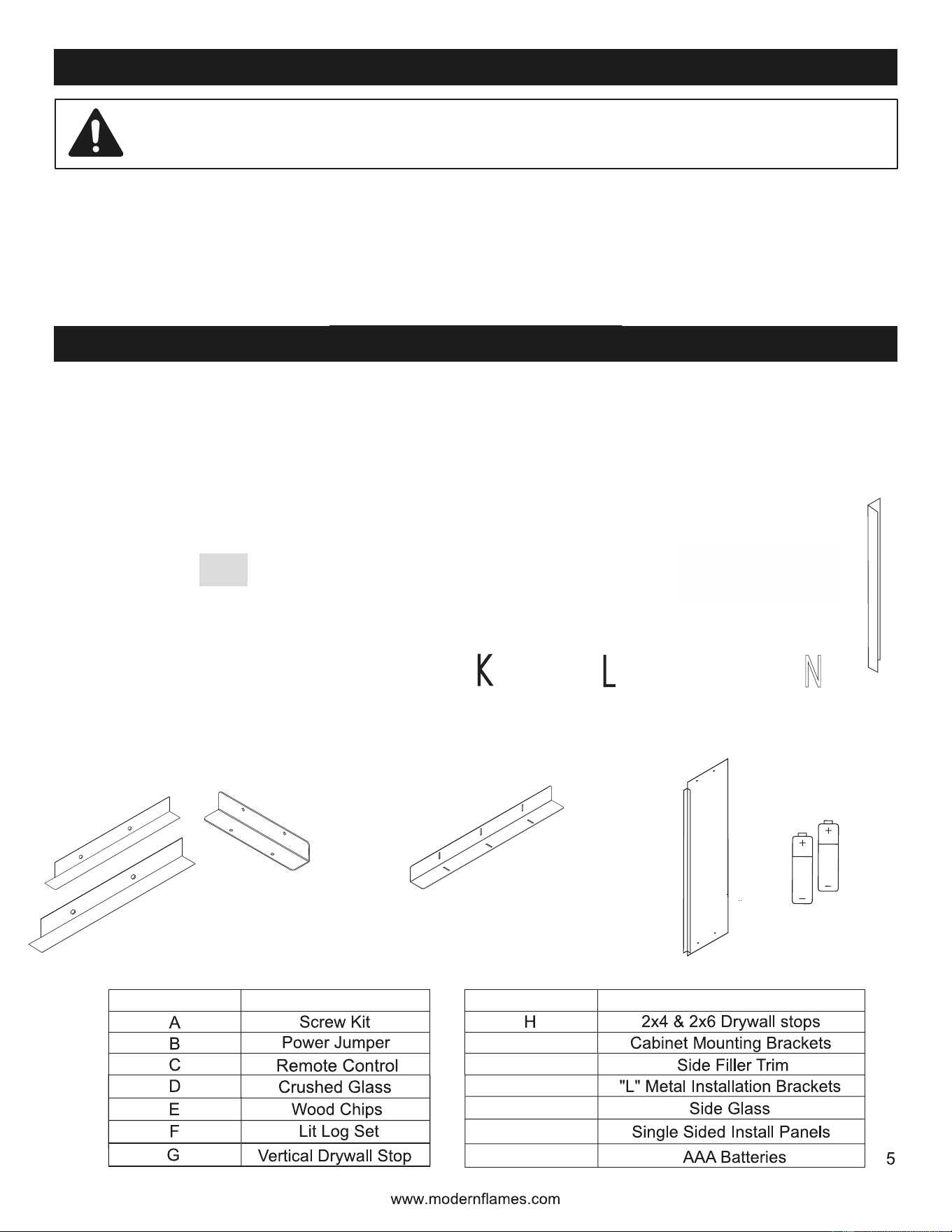
Parts and Hardware
PART NO. DESCRIPTION
PART NO. DESCRIPTION
Fireplace flame screen has a protective plastic film to protect during shipping and installation.
Once installed, gently remove protective plastic film from the front and back, ensuring not to
damage film.
Remove all parts and hardware from the carton and place them on a clean, soft, dry surface. Check
the parts list to make sure nothing is missing. Dispose of packaging materials properly. Please recycle
whenever possible.
Note: Ember bed acrylic and glass may have protective film on both sides. Ensure to check prior to
installing.
K
L
M
N
N
I
J
M
(Preinstalled)
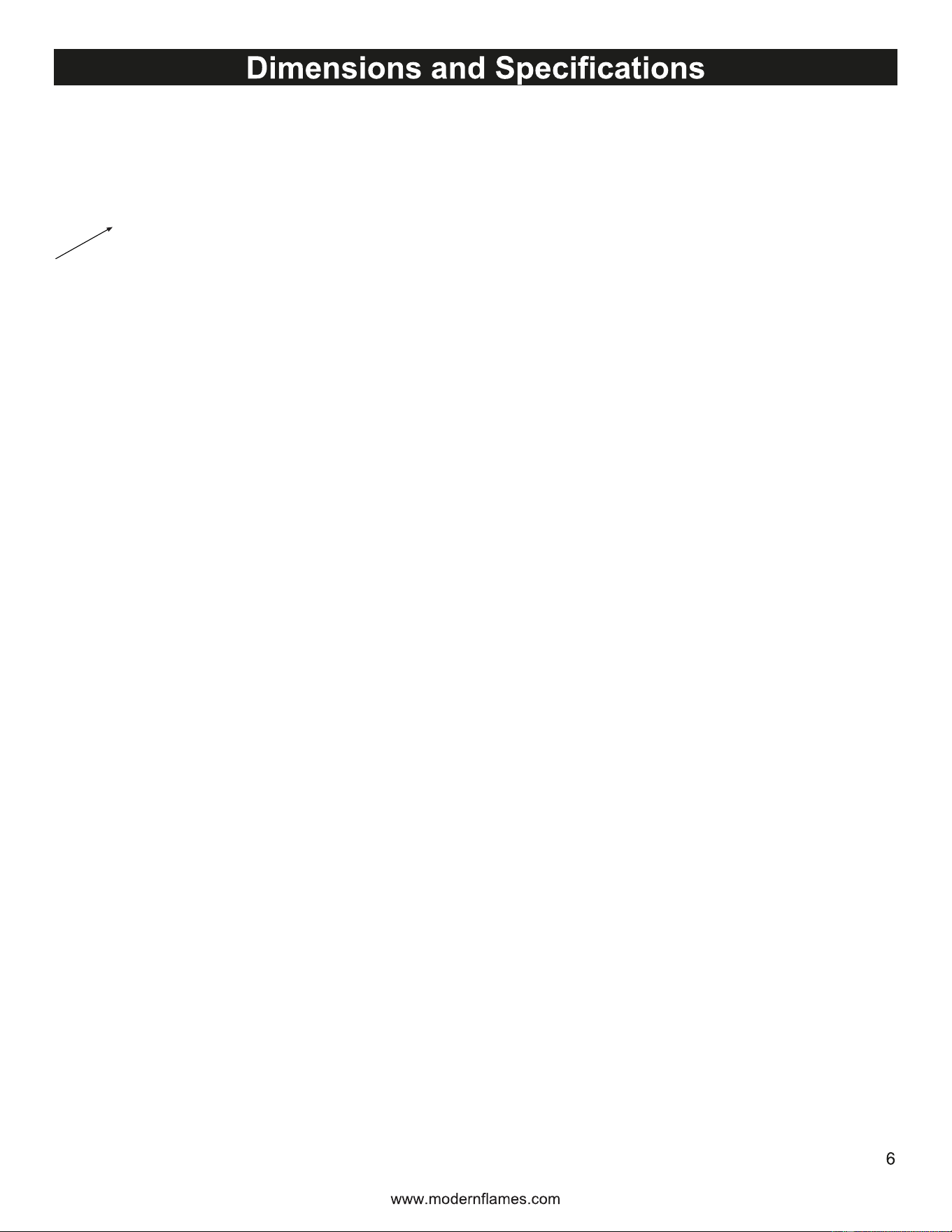
Note: Use this page for appliance size and orientation. Fireplace serial number is located within the viewing
area of the front side of the fireplace. It is on the right access panel.
Measurements are adjustable
REAR/SIDE B
FRONT/SIDE A
*
*
*
*
*
*
*
HDMI IN
KNOCKOUT
7
www.modernflames.com
Glass Removal/Installation
Removing Front and Back Glass
With one hand on the front glass to prevent it from falling, remove the four screws (two per bracket) and
two brackets from the underside of the viewing area of the fireplace. Set the screws and brackets aside.
Carefully tilt the top edge of the glass away from the appliance. Once the top edge of the glass is free
from the fireplace, lift the glass to fully remove it. Place the glass on a soft, nonabrasive surface.
Reverse these steps to re-install the front and back glass.
This product includes a GLASS panel. Always use extreme caution when handling glass.
Failure to do so could result in personal injury or property damage.

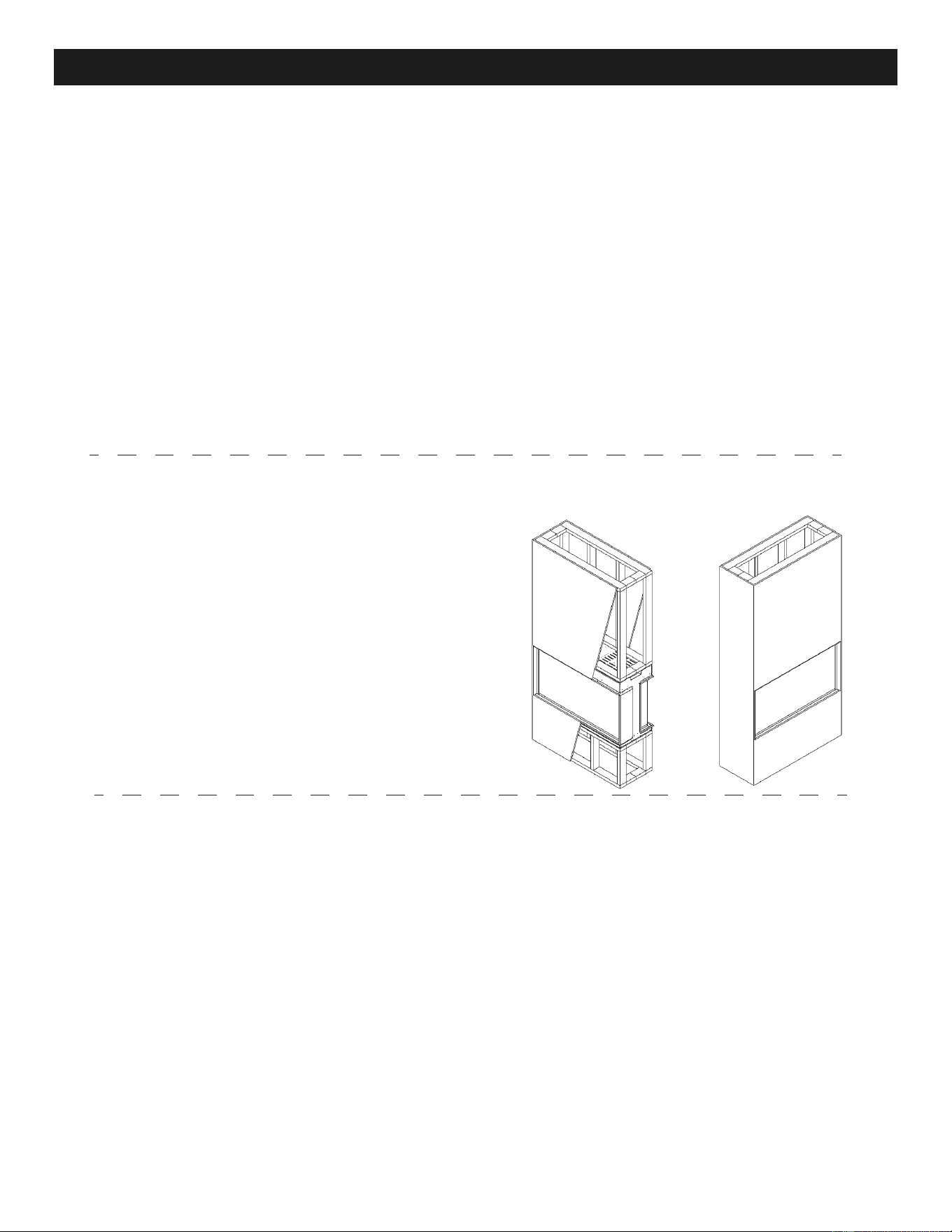
Adding the Side Glass
• Remove the side glass pieces (4 pieces) from the accessories box and unwrap the
protective plastic.
• With the front glass removed, insert the side glass at an angle, inside the viewing area of the
fireplace.
• Insert the top of the side glass into the glass channel and rotate the bottom of the glass until
it is vertical.
8
www.modernflames.com
Side Glass Installation
• Once vertical, gently place the bottom of the side glass in the bottom channel, next to the
ember bed.
• Repeat for all four pieces of side glass.
GLASS
CHANNEL
9
www.modernflames.com
Installation Styles
These are the most common installation styles and can be used in any configuration.
Follow the installation section below.
See page 12 See page 12
See page 12 See page 12
See page 13 See page 13
For wall depth & position, see pages 10 & 11. Use page 6 for appliance dimensions.
Built-In Single-Sided Installation Built-In Bay Installation
Island Bay Installation Island Single-Sided Installation
Floating 2x6 Wall InstallationFloating 2x4 Wall Installation
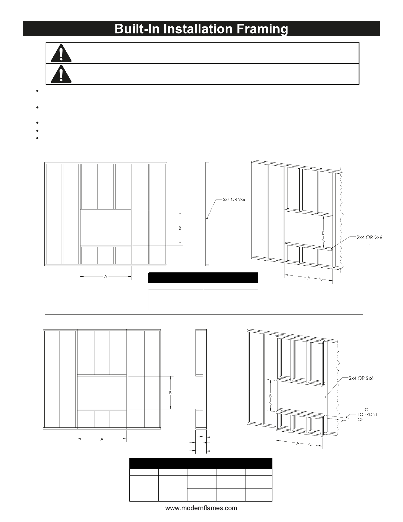
FLOATING
BAY
10
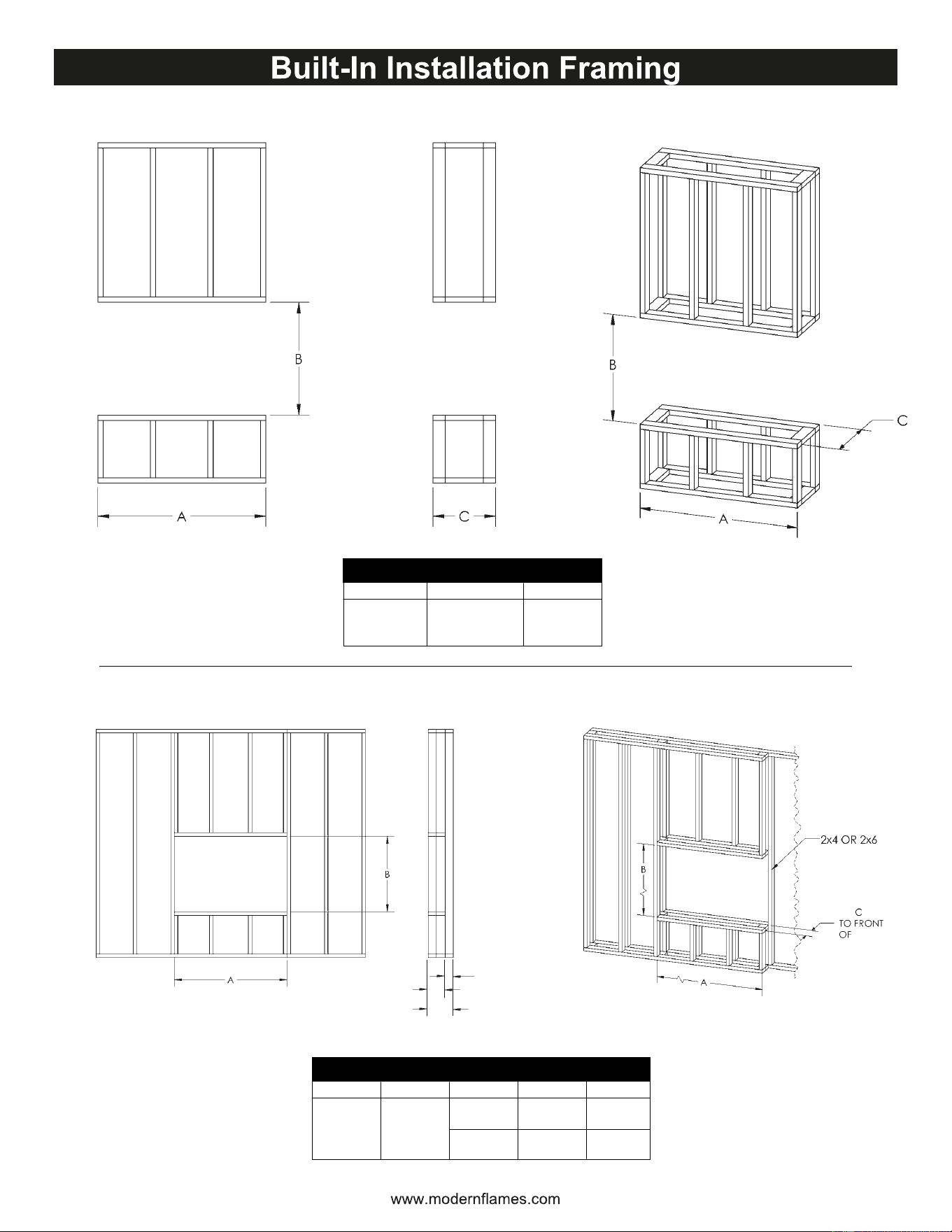
Before cutting any custom finishings (i.e. granite, marble, veneer, etc.) it is
recommended to double-check the dimensions of the actual fireplace.
Select a location that is not prone to moisture and is located at least 36" (914 mm) away from
combustible materials such as curtain drapes, furniture, bedding, paper, etc.
Measure the appliance and create a rough-in frame with electrical (see “Rough Framing
Dimensions”). Electrical to be at the top right of the rough-in framing.
Remove the front glass (see “Glass Removal/Installation” section).
Hold the appliance up to ensure it will fit into the framing.
Framing illustrations are for reference only. Consult your local building codes for appropriate
framing instructions.
Due to different materials used on different walls, it is highly recommended that
you consult with your local builder before you install this electric fireplace.
2x4 & 2x6 Rough Framing Dimensions
A B
48-5/16"
[1227mm]
32-3/8"
[822mm]
Rough Framing Dimensions
A B C D
Framing
48-3/16"
[1224mm]
32-3/8"
[822mm]
7-5/16"
[186mm]
2x4
2x6
6-5/16"
[160mm]
10-13/16"
[275mm]
11-13/16"
[300mm]
FRAMING
FRAMING
FRAMING
FRAMING
C
D
FRAMING
2x4 OR 2x6
11
ISLAND
SIDE EXPOSED
Rough Framing Dimensions
A B C
48-3/16"
[1224mm]
32-3/8"
[822mm]
18-1/8"
[461mm]
Rough Framing Dimensions
A B C D
Framing
48-3/16"
[1224mm]
32-3/8"
[822mm]
7-5/16"
[186mm]
2x4
2x6
6-5/16"
[160mm]
10-13/16"
[275mm]
11-13/16"
[300mm]
FRAMING
FRAMING
FRAMING
C
D
FRAMING
2x4 OR 2x6

Built-In Installation
Determine the desired installation style. See
If installing:
• Single-Sided – No changes required. Optionally, install the filler trim to remove the gap between
the side glass and the side plate. To do so, remove the side plate, install the filler trim using the
same mounting holes as the side plate, and then reinstall the side plate over the filler trim.
• 2-Sided – Remove the side plate covering the side glass on the exposed side of the fireplace.
Install the drywall stop (shipped loose) on the exposed side of the fireplace. Store the removed
side plate and extra drywall stop in a safe place.
• 3-Sided/Bay – Remove the side plates covering the side glass on both sides of the fireplace.
Install the drywall stops (shipped loose) where the side plates were. Store the side plates in
a safe place.
“Installation Styles” on page 9.
Prepare the framed opening according to the “Framed Opening Dimensions” chart for the
selected installation style.
Ensure an appropriate dedicated power circuit is provided at the top
Remove the front glass. See “Glass Removal/Installation” on page 7.
Install the “L” Metal Nailing Flanges to both the top and bottom of the fireplace. Pay special
attention when installing the “L” Metal Nailing Flanges as there are multiple sets of mounting
holes depending on the installation style. The “L” Metal Nailing Flanges are only required on
either the front or the back of the fireplace; not both.
12
www.modernflames.com
right of the frame opening.
SINGLE FACE INSTALL REMOVE SIDE PLATE
INSTALL SIDE DRYWALL STOPS
INSTALL FILLER TRIM

• Mount the fireplace in its final installation location before installing the cabinet mounting brackets.
• Remove the Side Plates and install the Side Drywall Stops as shown in the 3-Sided/Bay
Installation section.
• Install the four cabinet mounting brackets. Position two near the top of the fireplace, one on each
side, and two near the bottom, one on each side.
◦ Using screws from the hardware kit, secure the upper cabinet mounting brackets to the
fireplace with two screws per bracket.
◦ Remove the two screws along the lower
front edge of the fireplace and reuse them
to install the lower cabinet mounting
brackets.
• If using the Studio Suite Mantel Package,
install it according to its installation instructions.
If constructing a custom finish mantel,
complete the finish installation as required.
For 2x4 or 2x6 floating installations, the Studio Suite Mantel Package (sold separately) is
recommended for a finished appearance. A custom-built finish mantel may also be used. In either
case, the included Cabinet Mount Brackets must be installed for this type of installation.
Hardwire the fireplace to the dedicated power circuit.
See “Hardwiring Installation” on page 14.
Install the fireplace in the framed opening. Adjust the
adjustable feet as needed to ensure the fireplace is level.
Fasten the fireplace to the framing using the “L” Metal
Nailing Flanges and drywall screws that have a minimum
length of 1-1/4” (32mm).
Mask the exposed viewing area of the fireplace prior to
texturing/finalizing the framed wall.
Decorate according to the media installation guide. See
‘’Lit Log and Crushed Glass Installation’’ on page 18.
Install the front and back glass.
See “Glass Removal/Installation.”
13
Built-In Installation (Continued)
INSTALL CABINET
MOUNTING BRACKETS
14
www.modernflames.com
Hardwiring Installation
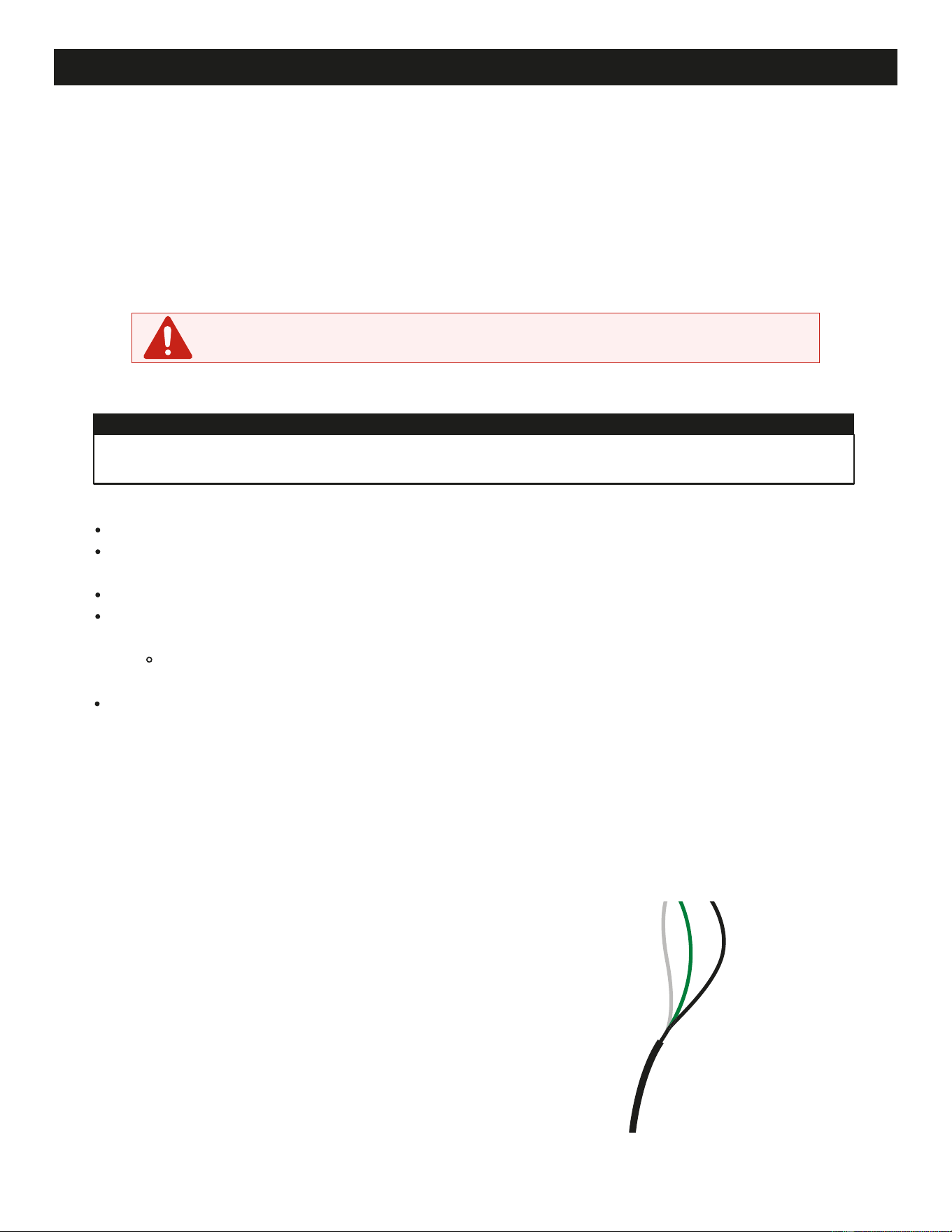
120 Volt Power (4,100 BTU’s):
The appliance must be electrically connected and grounded in accordance with local codes. In the
absence of local codes, use the current CSA C22.1 Canadian Electrical Code in Canada or the
current ANSI/NFPA 70 National Electrical Code in the USA.
Ensure power from the circuit breaker is off.
Remove the 2 securing screws from the junction box cover plate, located on the top, right-hand
side of the appliance, as viewed from the front.
Install the power supply wire through the junction box cover plate.
From the power supply wire, connect the green/bare copper wire to ground (G), the white wire to
neutral (N), and the black wire to Line1 (L1).
Note: L2 is only for 240V applications or when jumper is required. See heater configuration
table for jumper requirements.
• Resecure the junction box cover plate using the 2 screws previously removed.
Only 3 terminals will be used in the appliance junction box: white (neutral), black (power L1), and
green/bare (ground) that are connected to 120V power source (circuit breaker panel).
NOTE: A dedicated 15 amp is required.
A 20 amp breaker is preferred.
TURN OFF POWER FROM CIRCUIT BREAKER FIRST
Note:
JUNCTION BOX
COVER PLATE
This fireplace is equipped with the ability to optionally wire with 240 volts, which will supply 8,200
BTU’s of heat.
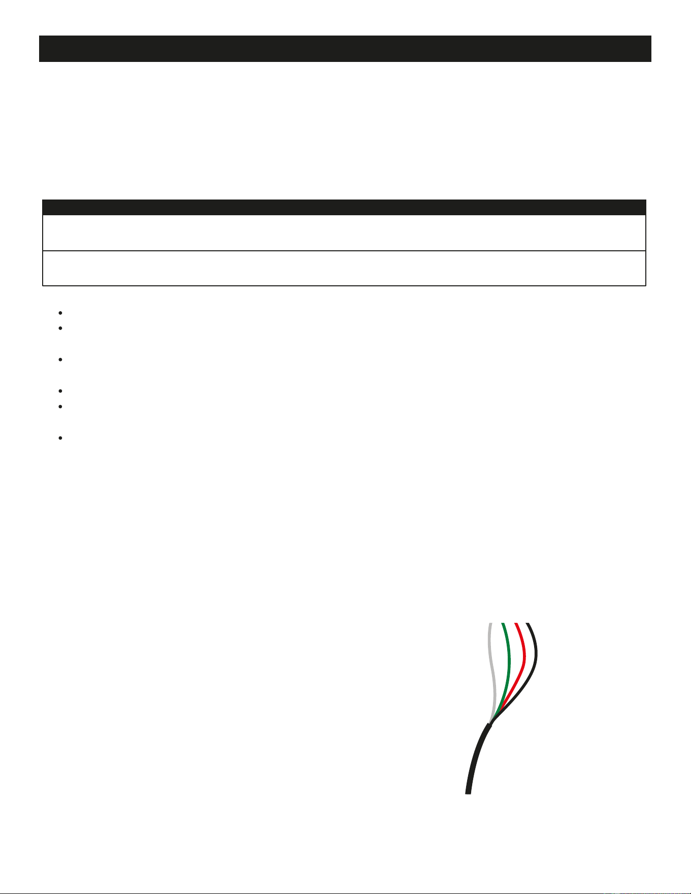
240 Volt Power (8,200 BTU’s):
Hardwiring Installation (Continued)
All 4 terminals will be used in the appliance junction box: white (neutral), black (power L1), red (power L2),
and green/bare (ground) that are connected to 240V power source (circuit breaker panel).
240V supply connection must include a neutral. Connection must be 4 wires (3 primary wires and a
ground). L1 & L2 must be separate phases.
Note:
Remove the 2 securing screws from the junction box cover plate, located on the top, right-hand side
of the appliance, as viewed from the front.
On the terminal block, locate the fourth position terminal that has the label covering the L2 terminal.
The label indicates “220-240V Only”. Remove the label.
Install the power supply wire through the junction box cover plate.
From the 4-wire, 240 volt power supply wire, connect the green/bare copper wire to ground (G),
the white wire to neutral (N), the black wire to Line1 (L1), and the red wire to Line2 (L2).
Re-secure the junction box cover plate using the 2 screws previously removed.
JUNCTION BOX
COVER PLATE
www.modernflames.com
15
Ensure power from the circuit breaker is off.
A dedicated 240V, split-phase, 15 amp circuit is required.
A 20 amp circuit is preferred.
Heater Configuration
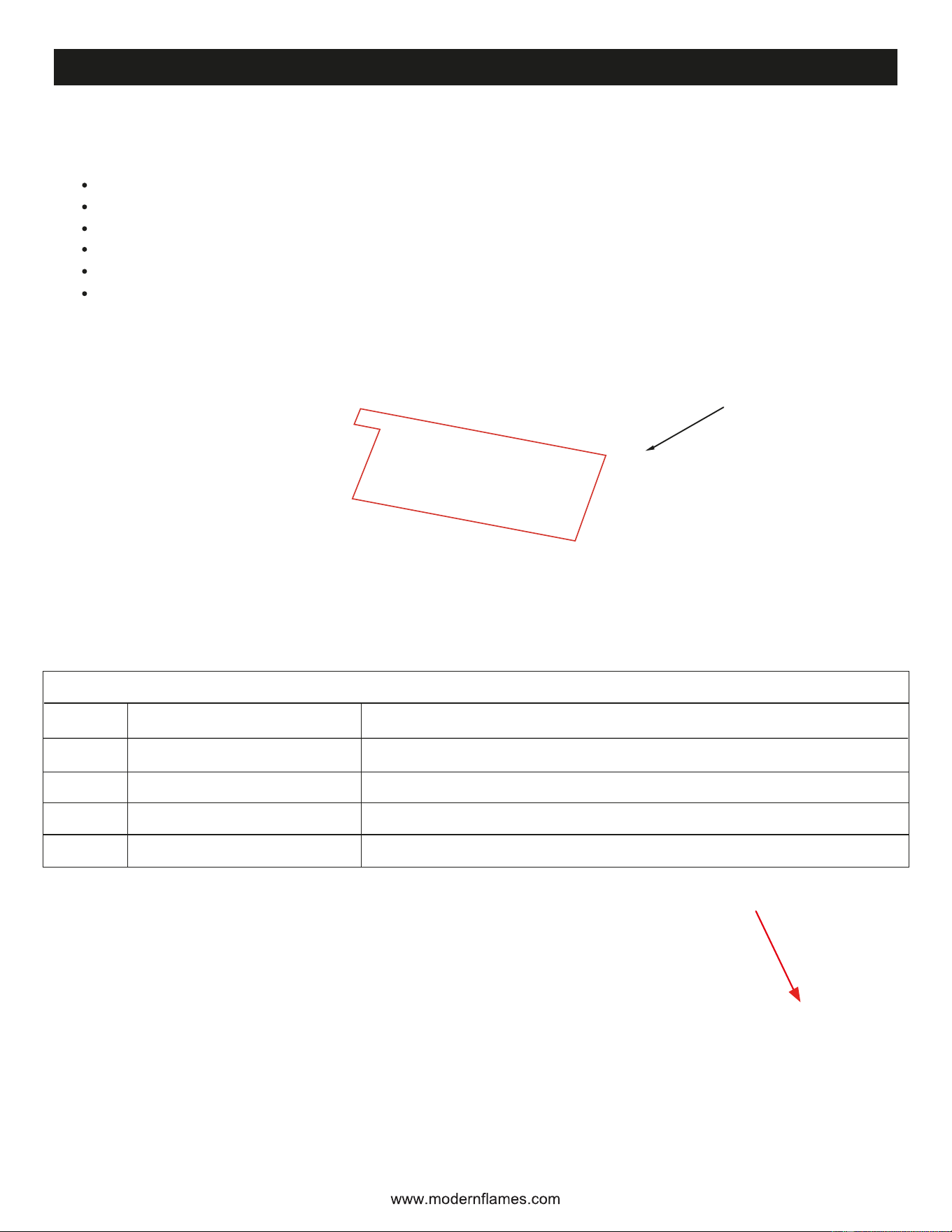
Configuring the fireplace for the desired heater outputs dip switch setting:
Ensure power to the unit is OFF prior to setting the PCB dip switches.
Remove front glass if not already removed.
Open PCB Access panel, located on the front right of the fireplace.
Locate and set PCB dip switches to desired heat setting. See below settings table and figures.
Turn power ON to the fireplace and test desired setting is achieved.
If the desired setting is not achieved confirm PCB dip switch settings and reset power to the
fireplace. Reassemble.
Settings
A
B
C
D
A
B
C
D
Front & Back heat enabled.
Front heat only.
Back heat only.
No Heat.
Heater enabled for both the FRONT and the BACK of the fireplace.
Heater disabled ONLY for the BACK of the fireplace.
Heater disabled ONLY for the FRONT of the fireplace.
Heater disabled for both the FRONT and the BACK of the fireplace.
Description
Dip switch settings examples
Additional info
DIP Switch Location
NOTE: Ensure the fireplace terminal block is wired according to the table on the following page. Fireplace
will need to be power cycled for settings to be achieved, therefore ensure power is OFF prior to setting
PCB dip switches.
16
PCB ACCESS
PANEL
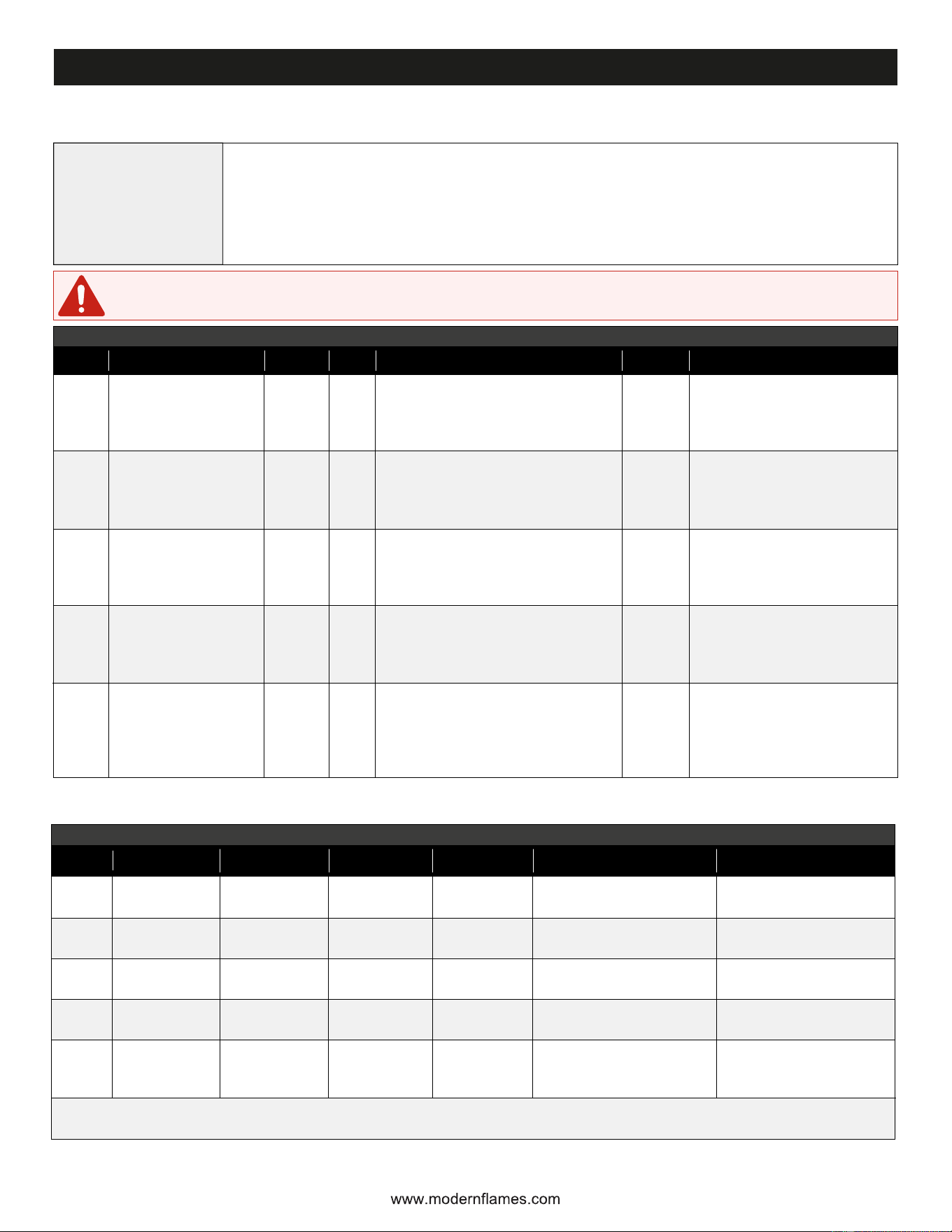
Configuring the fireplace for the desired heater output. Confirm PCB DIP switch settings and
terminal block wiring before applying power.
1. Turn power OFF before setting PCB DIP switches or changing terminal block wiring.
2. Remove front glass if not already removed and open the PCB access panel at the front right
of the fireplace.
3. Set the PCB DIP switch to the desired heater setting, then wire the terminal block according
to the configuration table below.
4. Power cycle the fireplace after changing settings, then test for the desired heater operation.
Note: 120 V configurations use a dedicated 15 A minimum circuit; a 20 A circuit is preferred. For 240 V, use a dedicated
split-phase circuit with neutral.
Final check: If the desired setting is not achieved, confirm PCB DIP switch settings, confirm terminal block wiring, reset
power to the fireplace, and retest before reassembly.
Safety note: Never install the L1-L2 on a 120V supply with the DIP Switches set to ‘’A’’. The jumper will backfeed L2
from L1 causing excessive load on the circuit. The jumper is never to be used for 240V applications.
WARNING: Never install the L1-L2 jumper on a 120 V supply with DIP switch set to “A.” The jumper will backfeed
L2 from L1, causing excessive load on the circuit. The jumper is never to be used for 240 V applications.
Heater Configuration (Continued)
Before
configuring
Step 1: Select Heater Configuration
Option Heating Option
Supply
DIP Terminal Block / Circuit Connections
L1-L2
Jumper
Heater Output
1
2
3
4
5
Front/Back 120 V
(Low Heat Only)
Front Only 120 V
(Low & High Heat)
Back Only 120 V
(Low & High Heat)
Heater Disabled
Front/Back 240 V
(Low & High Heat for
both sides)
120 V
120 V
120 V
120 V
240 V
(4-wire)
A
B
C
D
A
No
Yes
Yes
No
No
L1: Yes
L2: No
Neutral (N): Yes
Ground (G): Yes
L1: Yes
L2: Yes, via L1-L2 jumper
Neutral (N): Yes
Ground (G): Yes
L1: Yes
L2: Yes, via L1-L2 jumper
Neutral (N): Yes
Ground (G): Yes
L1: Yes
L2: No
Neutral (N): Yes
Ground (G): Yes
L1: Yes
L2: Yes
Neutral (N): Yes
Ground (G): Yes
L1 & L2 must be separate phases
Front: 600 W LOW
Rear: 600 W LOW
Total: 1200 W
Front: 1200 W LOW + HIGH
Rear: 0 W
Total: 1200 W
Front: 0 W
Rear: 1200 W LOW + HIGH
Total: 1200 W
Front: 0 W
Rear: 0 W
Total: 0 W
Front: 1200 W
Rear: 1200 W
Total: 2400 W
Step 2: Verify Electrical Load and Breaker Size
Option
Front Heater
Watts (W)
Rear Heater
Watts (W)
Total Watts
(Heaters only)
Total Amps
(Heaters only)
Fireplace + Heaters
Total Amps
Approved Breaker Size
1
2
3
4
5
600
(LOW)
1200
(LOW + HIGH)
0
0
1200
15 Amp
(20 Amp preferred)
15 Amp
(20 Amp preferred)
15 Amp
(20 Amp preferred)
15 Amp
2-pole 15 Amp
(2-pole 20 Amp preferred)
600
(LOW)
0
1200
(LOW + HIGH)
0
1200
1200
1200
1200
0
2400
10
10
10
0
10
L1 = 11.5 A
L1 = 11.5 A
L1 = 11.5 A
L1 = 1.5 A
L1 = 11.5 A
L2 = 10 A
Neutral = 1.5 A imbalance
17
Lit Log and Crushed Glass Installation
18
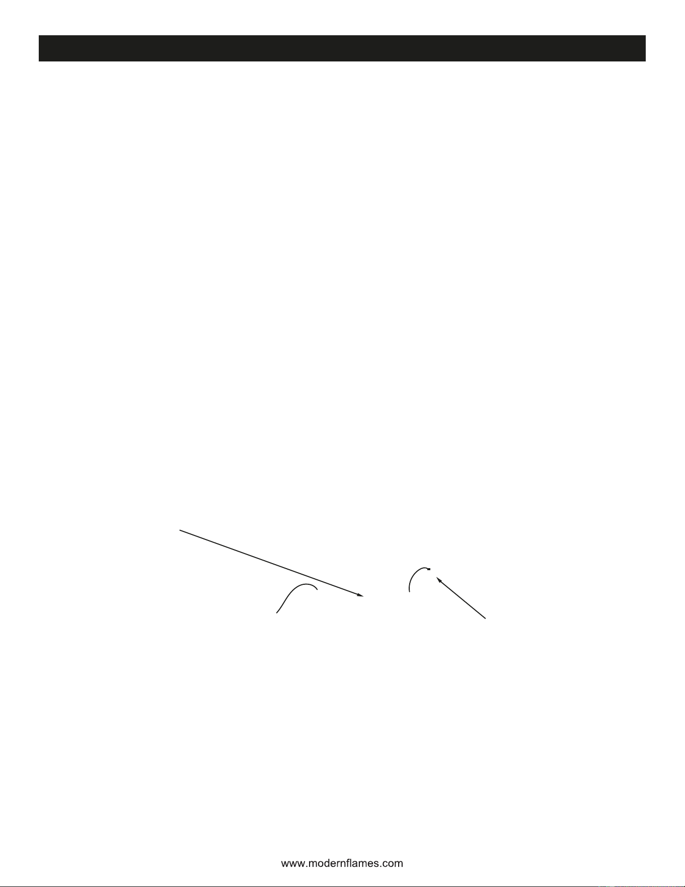
• Front glass must be removed and the appliance must be mounted in its final location before the log
set and crushed glass are installed.
• Install the log set into the fireplace by threading the wired connection through the textured acrylic
and plugging into the log set electrical connector with the painted side of the logs facing out. The log
set electrical connector is located on the back right side of the ember bed. Ensure careful alignment
when plugging in the connector, as it can only be installed in one orientation. (Connection back left
for back of fireplace).
• Place acrylic and log set on the ember bed tray. Ensure it is behind the glass track.
• After the log set has been installed, arrange the glass media on the ember bed so that the entirety
of the acrylic ember bed is covered. Sprinkle the wood chips over the crushed glass as desired.
Ensure the front glass track is clear of media as this will prevent the front glass from being reinstalled.
• Repeat these steps for the opposite side of the fireplace.
Note: Ensure care is taken when handling logs and installing into the fireplace to avoid damage to logs
and screen.
PLUG
LOCATION
NOTE: IT WILL BE ON
OPPOSITE SIDE FOR
BACKSIDE.
WIRE PATH
GOES THROUGH
SECOND ACRYLIC
LOG TRAY
BAG OF WOOD CHIPSBAG OF CRUSHED GLASS

Sound Modes
Log Lighting
The electric fireplace is equipped with an integrated audio system featuring multiple selectable sound
modes to enhance environmental realism. To change sound modes, use the remote to turn on the on-
screen controls and select the desired Sound Mode this can also be done or by using the Modern
Flames App.
Normal Mode
A classic fireplace crackling audio effect designed to recreate the comforting sound of a real wood-burning
fire.
Starry Night Mode
A calm nighttime ambient sound featuring soft nature-inspired audio for a relaxing atmosphere.
Stormy Night Mode
An immersive nighttime storm with rain and distant thunder for a cozy, dramatic setting.
Bluetooth Mode
Connect your Bluetooth-enabled device to play music or other audio through the fireplace speaker system.
The fireplace features illuminated reactive logs with three lighting modes.
Breathing Mode
Provides a pulsing illumination which causes the brightness of individual logs to slowly increase and
decrease, emulating a real fireplace.
Active Mode
Dynamically adjusts log brightness in real-time based on fireplace sounds or Bluetooth audio, creating
a synchronized audio-visual experience.
Static Mode
Provides constant illumination for a steady log illumination effect.
19
www.modernflames.com
Operation
Read and understand this entire owner’s manual, including all safety
information, before plugging in or using this product. Failure to do so could
result in electric shock, fire, serious injury, or death.
Power
Turn on dedicated breaker. NEVER exceed the maximum amperage for the circuit. DO NOT plug other
appliances into the same circuit.
Methods of Operation
This electric fireplace can be operated by the TOUCH CONTROL PANEL located on the UPPER right
corner of the fireplace (both sides), by the battery-powered REMOTE CONTROL, or by the MODERN
FLAMES APP using a smart phone or tablet.
Pairing the Remote
• With the fireplace ON, press and hold the Power button on the fireplace touch controls for 5
seconds until you hear a beep from the fireplace.
• Within 5 seconds of the fireplace beeping, repeatedly press the power button on the remote until
the fireplace beeps again.
• Pairing must be completed within 5 seconds or the fireplace pairing will time out of pairing mode.
Clearing the Remote
• With the fireplace ON, press and hold the Downlight and Ember Bed buttons on the touch controls
for 5 seconds, until you hear a beep from the fireplace.
Master Power Switch
Located next to the Touch Control Panel, on the front side, is the Master Power Switch. Ensure the rocker
switch is pressed in the “On” position prior to operating the fireplace.
Note: After resetting the Master Power Switch or from a loss of power, the fireplace takes 20-30 seconds
before the fireplace is fully booted and operational. Always allow the fireplace to fully shut down or boot
up before performing any functions.
20
www.modernflames.com
MASTER POWER SWITCH
21
www.modernflames.com
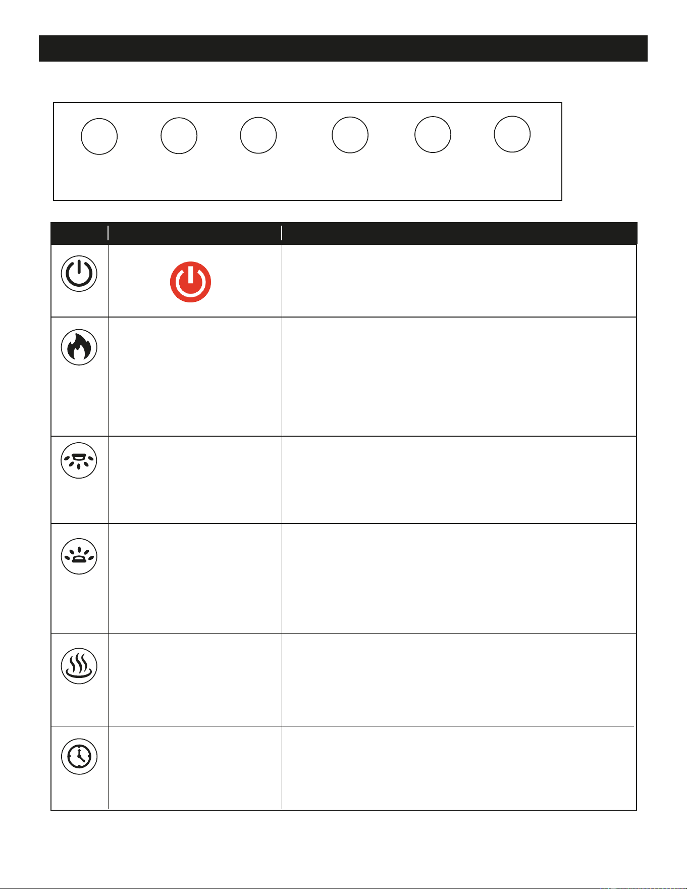
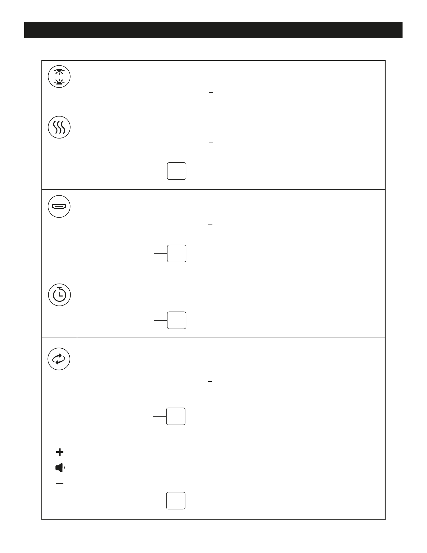
Power: Cycles the fireplace ON/OFF.
Secondary Function: Long Press - Places the fireplace in
remote pairing mode.
Button On-screen pop up Description
Switches between color presets and flame styles.
Preset Colors: Yellow (default), Orange, Blue, Aqua,
Purple, White. Cycles through all preset colors first before
switching to the next flame style.
Secondary Function: Long Press - Places the fireplace in
App pairing mode.
Switches between 10 RGB Downlight colors and
auto cycle. Orange, Red, Blue, Yellow, Green, Purple,
Aqua, Magenta, Rose, White, Autocycle.
Secondary Function: Long Press - Enables/Disables
night mode. Color can be cycled while in night mode.
Switches between 10 RGB Ember Bed colors and an auto
cycle. Orange, Red, Blue, Yellow, Green, Purple, Aqua,
Magenta, Rose, White, Autocycle.
Secondary Function: Long Press - Enables/Disables the
active log lights. Enabled by default.
Heat cycles between OFF/Fan/Low/High.
Secondary Function: Long Press - Enables/Disables the
heater lockout. Applies to active side only.
Timer to turn OFF unit at desired time. From NO timer to
8 hours.
Secondary Function: Press & Hold 5 seconds to switch
video inputs from the flame video to HDMI, and vice versa.
Touch Control Panel
TIMER HEAT EMBER
BED
FLAME
POWER
DOWNLIGHT
FRONT OF FIREPLACE
EDGE
OF FIREPLACE
22
www.modernflames.com
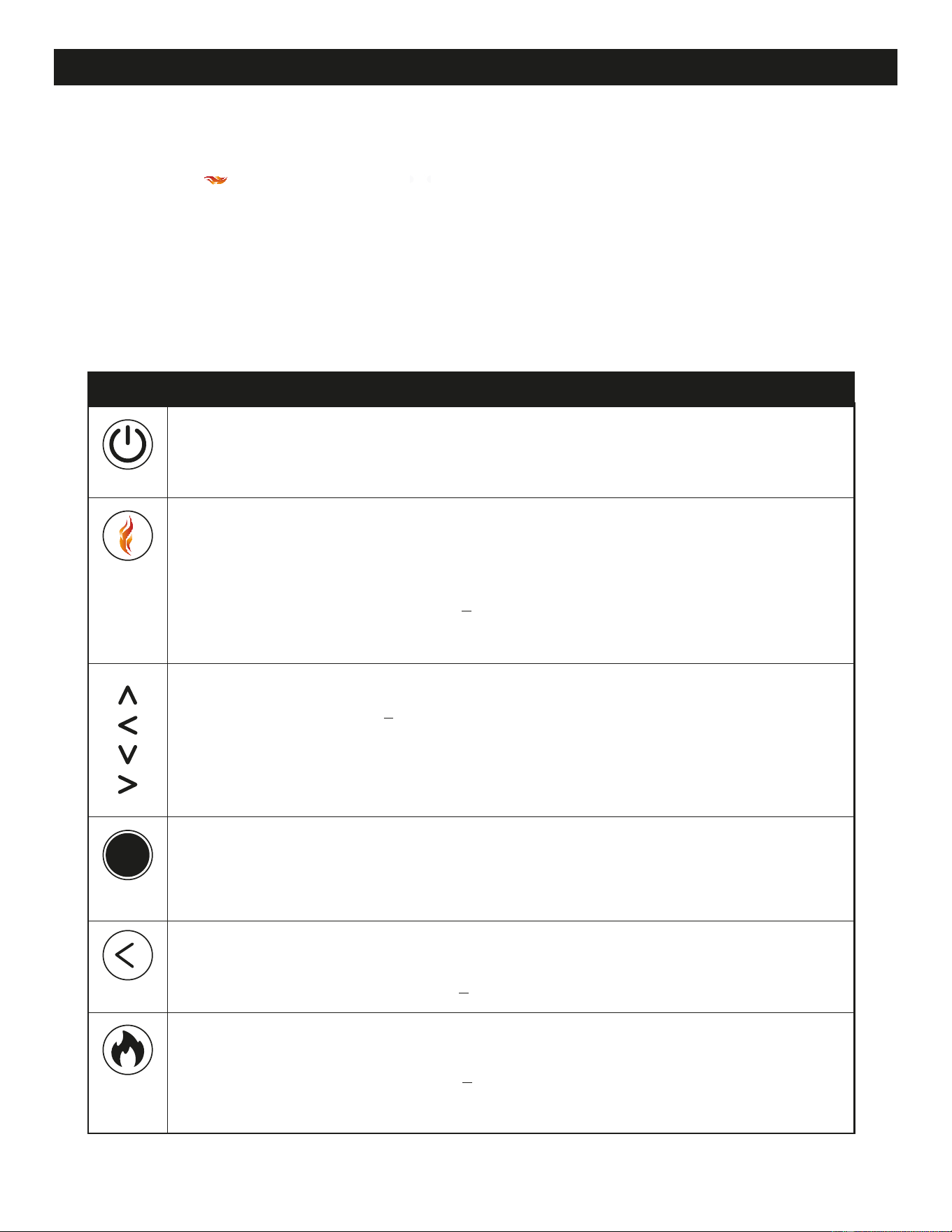
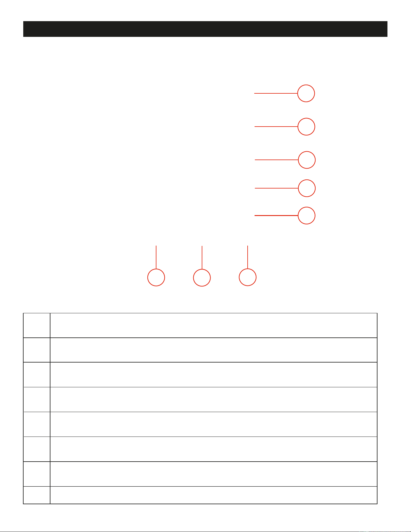
Power Button:
Primary Function: ON/OFF.
Secondary Function: Pairs Remote to Fireplace.
Arrow Buttons:
Fireplace Mode: Opens On Screen Control (PIP).
PIP Mode: Cursor/Selection.
Selection Button:
Back Button:
Fireplace Mode: Home page of PIP.
PIP Mode: Selector/OK Button.
Primary Function: Back Button and to exit secondary menus.
Secondary Function: Long Press Exit PIP
Flame Style Button:
Primary Function: Shortcut to Flame Style PIP.
Secondary Function: Long Press Favorites Menu/Carousel is
highlighted/selected on PIP Home Page.
Remote Control
Remote Control Operation
Default/Home Button:
Primary Function: Reverts the flame settings to flame style 1, color yellow. Ember
bed and downlight changes to Modern Flames orange. Flame speed changes to
medium, sound level changes to medium, and sound mode goes to normal mode.
Secondary Function: Long Press Enters focus adjustment mode to fine tune
the screen focus using the arrows while in the menu.
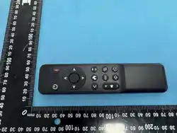
REMOTE #: 01-00251
23
www.modernflames.com
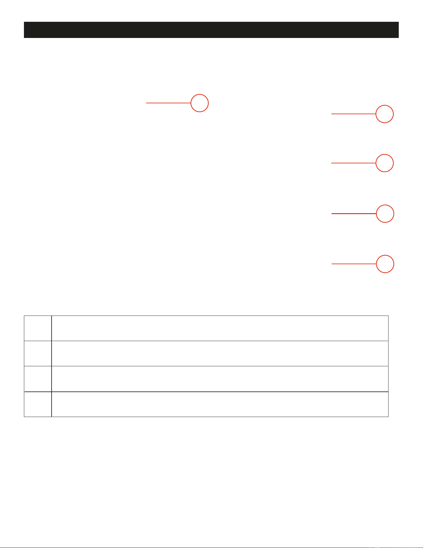
Lights Button:
Primary Function: Shortcut to Downlight/Ember bed PIP.
Secondary Function: Long Press Enables/Disables Night Mode. Color can be
cycled white while in Night Mode.
HDMI Mode Button:
Primary Function: Places fireplace in HDMI mode.
Secondary Function: Long Press Enables/Disables control of fireplace volume
using the streaming device remote also known as CEC control. Off by default.
Timer Button:
Primary Function: Shortcut to Timer PIP.
Secondary Function: N/A
Screen Flip Button:
Volume Buttons:
Primary Function: Screen default picture in picture is to the front of the fireplace.
When pressed, image flips 180°.
Secondary Function: Long Press Enables the flame brightness PIP.
There are 6 levels: 50% / 60% / 70% / 80% / 90% / 100%
Independent Up and Down buttons toggle between volume levels.
Levels: Off, Low, Medium, High.
Secondary Function: N/A
Remote Control (Continued)
Heater Button:
Primary Function: Shortcut to Heater PIP.
Secondary Function: Long Press Enables/Disables the heater lockout. Applies
to active side only.
ON-SCREEN POP UP
ON-SCREEN POP UP
ON-SCREEN POP UP
ON-SCREEN POP UP
ON-SCREEN POP UP
24
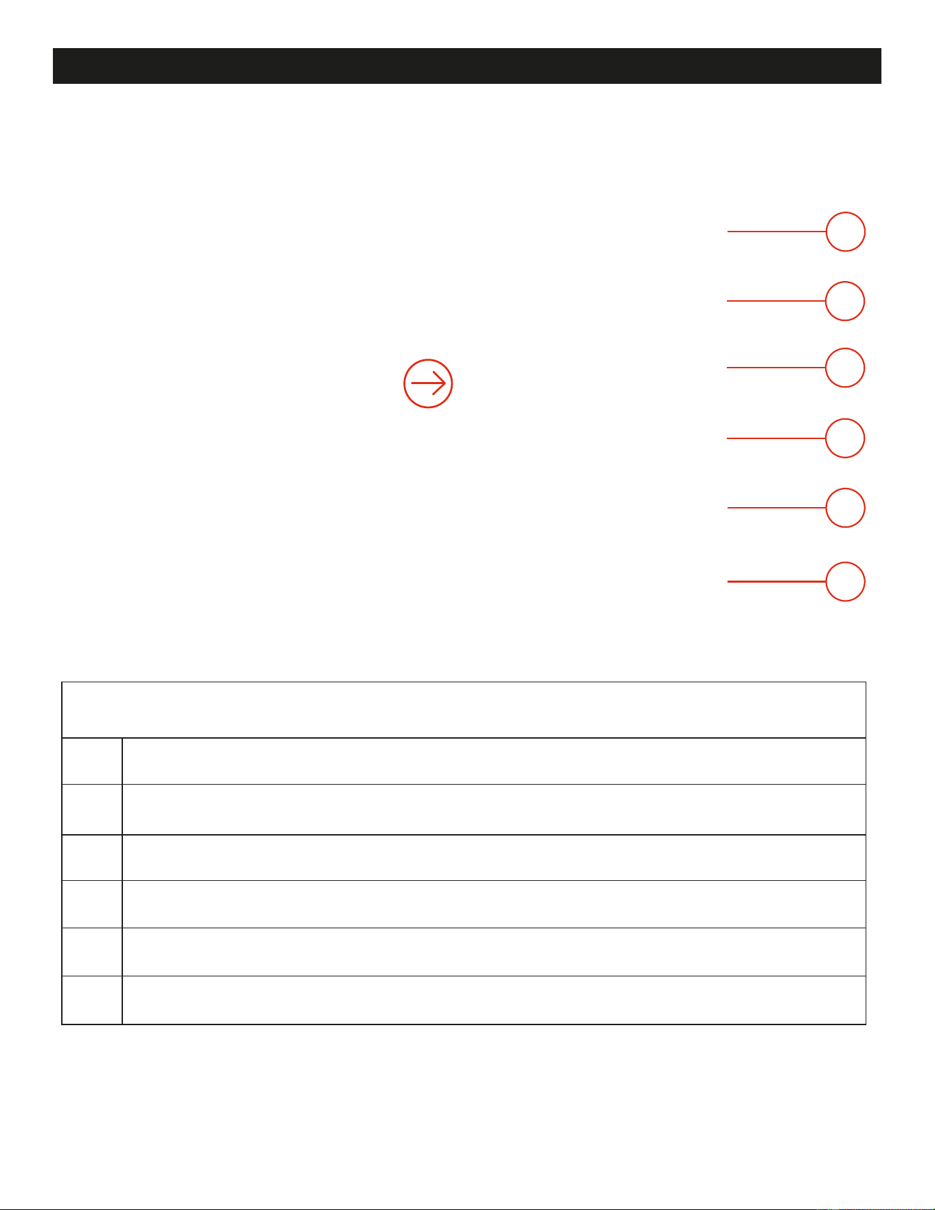
On Screen Controls
Flame Menu: Opens the flame style sub-menu for selecting different flame styles and colors.
4 styles with 6 colors for each style.
Note: Some on-screen controls may not be fully visible. Scroll up/down to view all on-screen controls.
1
2
3
4
5
6
7
8
Favorites: A quick access slider to change between the 6 favorited flame presets
as defined in the Modern Flames App.
Flame Speed: Changes the flame speed of the currently displayed flames. Cycles between
Slow, Medium, and Fast.
Flame Volume: Changes the sound effect volume of the fireplace between 4 different
volumes. Can cycle between Off, Low, Medium, and High.
Sound Mode: Changes the sound mode of the fireplace. Cycles between Normal, Starry
Night, Stormy Night, and Bluetooth.
Lights: Opens the lights sub-menu for changing the ember bed and downlight
colors, ember bed and downlight brightness, ember bed modes, log modes, and night mode.
Heater Button: Opens the heater sub-menu for turning on or off the front and/or back
heater and thermostat.
Timer Button: Opens the timer sub-menu for enabling an auto-shutoff timer.
1
2
3
4
5
6
7
8
www.modernflames.com
25
Style One: Opens the flame style one sub-menu.
Style Two: Opens the flame style two sub-menu.
Note: Flame images are for illustration only and may not match the flames in your fireplace.
Style Three: Opens the flame style three sub-menu.
Style Four: Opens the flame style four sub-menu.
1.1
1.2
1.3
1.4
1
www.modernflames.com
1.1
1.2
1.3
1.4
On Screen Controls (Continued)
26
www.modernflames.com
1.1.2
1.1.1
1.1.3
1.1.4
1.1.5
1.1.6
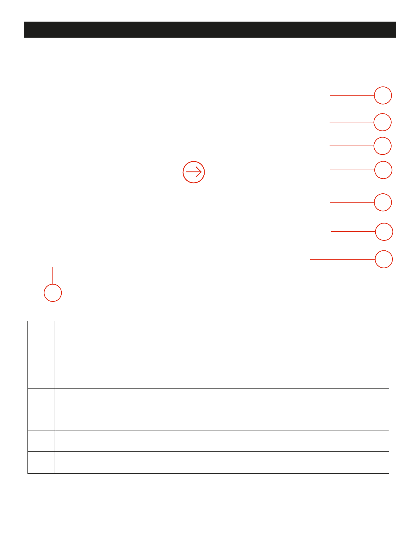
Note: Flame Style One (1.1), Two (1.2), Three (1.3), and Four (1.4) all function the same as below.
Yellow Flame Button: Changes the fireplace to the Yellow flame.
Orange Flame Button: Changes the fireplace to the Orange flame.
Blue Flame Button: Changes the fireplace to the Blue flame.
Green Flame Button: Changes the fireplace to the Green flame.
Purple Flame Button: Changes the fireplace to the Purple flame.
White Flame Button: Changes the fireplace to the White flame.
1.1.1
1.1.2
1.1.3
1.1.4
1.1.5
1.1.6
Note: Flame images are for illustration only and may not match the flames in your fireplace.
On Screen Controls (Continued)
On Screen Controls (Continued)
27
www.modernflames.com
6.1
6.2
6.3
6.4
6.5
6.6
6.7
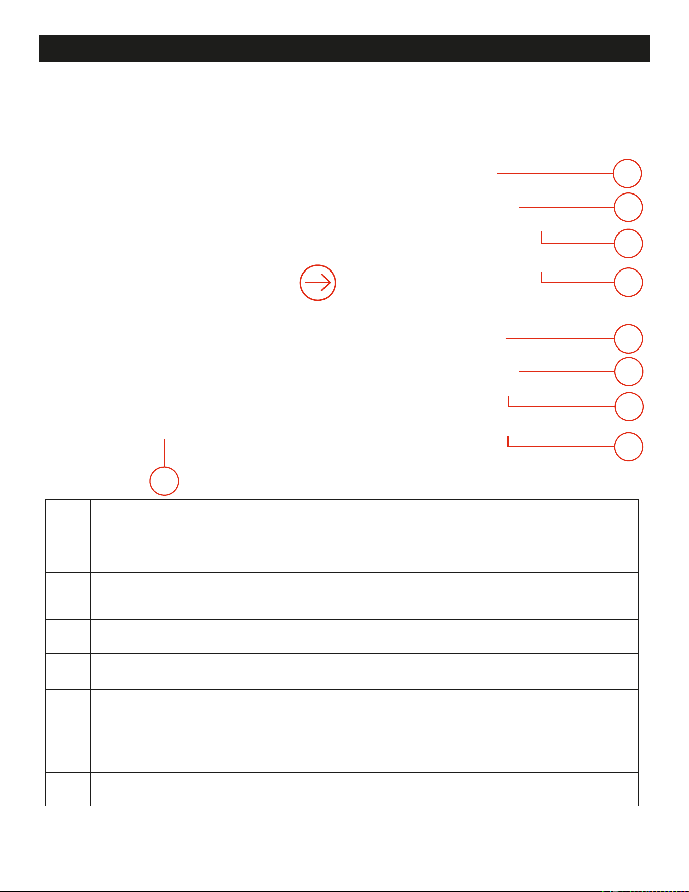
Ember Bed Light Color: Changes the color of the ember bed and log set. 10 preset colors
and 1 color cycle.
Ember Bed Brightness: Changes the brightness of the ember bed lights.
Ember Bed Mode: Changes the speed of the active ember bed. Switch between Slow,
Medium, Fast, and Static.
Log Mode: Changes the behavior of the log set. Switch between Breathing, Active, Static,
and Off.
Downlight Color: Changes the color of the downlight. 10 preset colors and 1 color cycle.
Downlight Brightness: Changes the brightness of the downlight.
Night Mode: Enables Night Mode. All features of the fireplace turn off except for the
downlight. Color can still be cycled.
6.1
6.2
6.3
6.4
6.5
6.6
6.7
6
28
www.modernflames.com
7.1
7.2
7.3
7.4
7.5
7.6
7.7
7.8
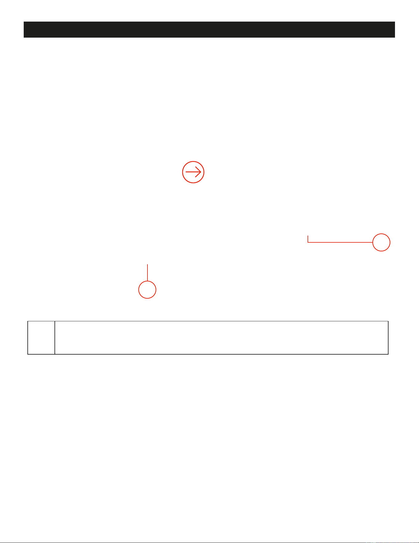
Front Thermostat: Shows the current ambient temperature for the front of the fireplace.
Pressing changes the scale of the fireplace between Fahrenheit and Celsius
Thermostat Toggle: Enable the use of the thermostat temperature slider for the front heater.
Disables level controls and cycles heater ON/OFF based on thermostat slider.
Thermostat Slider: Changes the thermostat value of the fireplace, enabling or disabling the
front heater at the set temperature. Once the set temperature is reached, heater will cycle
OFF/ON to maintain set temperature.
Heater Lever: Changes the settings of the front heater. Switch between Heater Lock
Out (disabled), Off, Recirculate (fan only), Low Heat, and High Heat.
Back Thermostat: Shows the current ambient temperature for the back of the fireplace.
Pressing changes the scale of the fireplace between Fahrenheit and Celsius.
Thermostat Toggle: Enable the use of the thermostat temperature slider for the back heater.
Disables levels controls and cycles heater ON/OFF based on thermostat slider.
Thermostat Slider: Changes the thermostat value of the fireplace, enabling or disabling the
back heater at the set temperature. Once set temperature is reached, heater will cycle
OFF/ON to maintain set temperature.
Heater Lever: Changes the settings of the back heater. Switch between Heater Lock
Out (disabled), Off, Recirculate (fan only), Low Heat, and High Heat.
7.1
7.2
7.3
7.4
7.5
7.6
7.7
7.8
7
Note: The displayed temperature may differ from the actual room temperature due to installation location,
room size, airflow, drafts, insulation, and other ambient conditions.
On Screen Controls (Continued)
29
www.modernflames.com
8.1
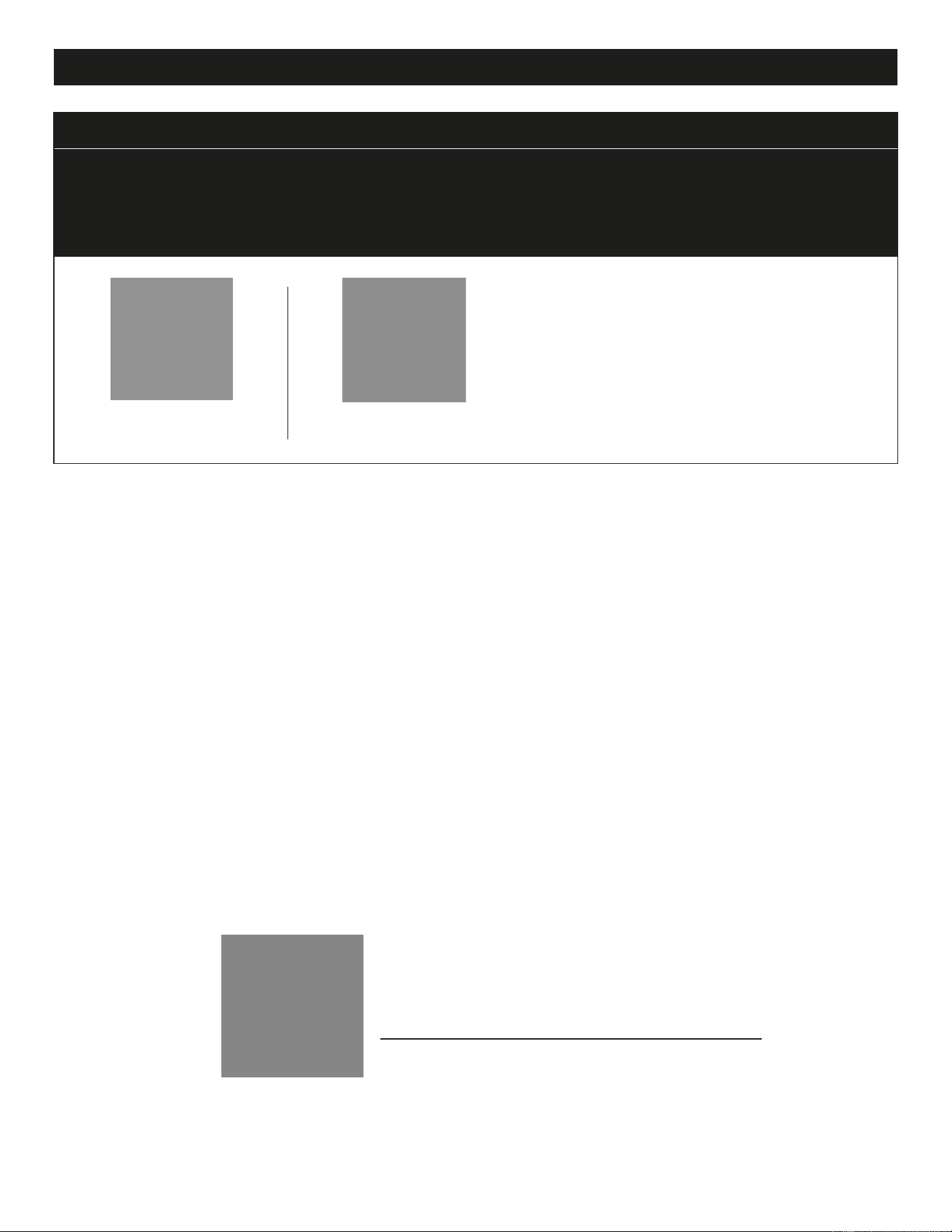
Preset Timer Options: Changes the amount of time for the fireplace to run before turning off.
Once the time has expired, all functions of the fireplace are turned off. Switch between 00 (off),
30 mins, and 1 hour increments up to 8 hours.
8.1
8
On Screen Controls (Continued)
30
www.modernflames.com
Download Smart Phone App
Smart Phone App Connection
Note: Download the Modern Flames App from your app store before connecting.
Important: Nova Clear fireplaces are compatible only with the Modern Flames App.
They are not compatible with the Modern Flames + App.
Note: The APP is subject to change without notice. Images shown may not represent current
APP configuration.
View the Modern Flames App User Guide
by scanning QR code.
https://www.modernflames.com/app-functionality/
Download Mobile App
• Gently lower the access panel until the panel hangs freely. Be careful of any wires that
may also rotate down with the service panel.
• Attached to the inside of the access panel is a small cover with an HDMI input, USB-C power
output, USB-A power output, and a 120V power plug.
Note: Although a USB-C and USB-A port is provided, some streaming devices may require the use
of a power adapter (not included) to have enough power to operate.
• Plug the streaming device (not included) into the HDMI plug and the appropriate power plug.
Ensure the wires are properly stored and out of the way of any of the internal fireplace components.
• Swing the access panel back into position and fasten with the three screws that were previously
removed.
• Replace the front glass that was previously removed.
Streaming Device
This fireplace is equipped with the ability to install a streaming device (not included) to allow the
user to stream their favorite streaming platform onto the fireplace. Most major brands of streaming
devices can be used. Some of the models tested with the fireplace include: Google Chromecast, Amazon
Fire TV Stick 4K, Roku Streaming Stick 4K, Apple TV 4K.
Note: The remote that came with the fireplace will be used to enter and exit streaming mode but
the streaming device will be controlled with the remote supplied with the streaming device. Ensure that CEC
is enabled to allow streaming device remote to control the fireplace volume. Some streaming devices only
broadcast IR signals for volume and will not control the fireplace audio. For those applications, you will have
to use the fireplace remote to control.
• From the back side of the fireplace, remove the glass face. See “Glass Removal/Installation” page 7.
• Looking at the ceiling of the viewing area, in the front, right-hand corner, find the three screws
that are holding the access panel in place.
• Remove the three screws and place them in a safe place. Ensure that one hand is kept on the
access panel at all times while in the closed position, to prevent it from swinging down and
causing damage to the fireplace.
Streaming Devices
31
www.modernflames.com
Caution: Customers assume full responsibility for any damage to the fireplace caused by installing a
streaming device.
Note: Installation of a streaming device in the streaming cavity may impact the streaming device
performance or lifespan.
Prior to opening access panel it is recommended that you remove the fireplace USB located
on the access panel. It can be left in, but caution must be taken when opening or damage to
the USB device or USB port may occur.

Streaming Devices (Continued)
32
www.modernflames.com
USB C/A
POWER
OUT ONLY
HDMI
INPUT
120V OUT

Remote Control Battery Information
• The remote control uses two AAA batteries (included).
Installing or Replacing the Remote Control Batteries
• Looking at the back of the remote, locate the removable battery compartment door.
• Gently slide the battery door downward, toward the bottom edge of the remote.
• If replacing the batteries, remove the old batteries and dispose of them in accordance with local
regulations.
• Insert the supplied batteries or new AAA batteries, ensuring the “+” and “–” ends align with the
markings inside the battery compartment.
• Replace the battery door by sliding it back into position from the bottom of the remote.
Temperature Limiting Control
This heater is equipped with a Temperature Limiting Control. Should the heater reach an unsafe
temperature, the heater will automatically turn off.
To Reset:
• Remove power from the fireplace. Wait 5 minutes. Unplug the fireplace or turn off the
appropriate breaker at the circuit breaker box.
• Inspect the fireplace to ensure no vents are blocked or clogged with dust or lint. Using a vacuum
can help clear the areas if needed.
• Restore power to the fireplace.
• If the problem continues, have the wiring and outlet inspected by a professional.
Important Warnings
33
www.modernflames.com
Note:
• When the heater is first turned on, a slight odor may be present. This is normal and should not
occur again unless the heater is not used for a long period of time.
• To improve operation, aim the remote control at the front of the fireplace and operate no further
than 15 ft or 4.5 m. (Maximum operating range = ~20 ft / ~6 m).
•
Quickly pressing of buttons on remote or manual controls without allowing the fireplace to complete
the previous operation may result in operational errors. Allow the fireplace to complete each
command before issuing another.
• Metal surfaces: Clean with a soft cloth lightly dampened with a mild cleaner.
• Glass: Use a good quality glass cleaner and dry thoroughly with a lint-free cloth or paper towel.
For best results, apply glass cleaner to the cloth instead of spraying it directly onto the fireplace.
• Vents: Use a vacuum or soft brush attachment to remove dust, dirt, and lint from the vent areas.
• Nano Screen: Note the screen is very fragile; care must be taken when cleaning. Use air to blow
off any dust before cleaning. Then use only a high-quality microfiber cloth dampened with water
to clean. Do not use abrasive cleaners or harsh liquids to clean. Avoid excess pressure on the
screen when cleaning.
• Projection lens: Note the lens is fragile; care must be taken when cleaning. Turn OFF the fireplace
before cleaning, and do not look into the projector lens while ON. Use air to blow off any dust
before cleaning. Then use only a high-quality microfiber cloth to clean. Do not use abrasive cleaners
or harsh liquids to clean. Avoid excess pressure on the lens when cleaning.
Always turn the heater OFF, allow it to cool, and disconnect before cleaning, performing maintenance,
or moving this fireplace. Failure to do so could result in electric shock, fire, or personal injury.
Never immerse in water or spray with water. Doing so could result in electric shock, fire, or
personal injury.
Cleaning
• Do not use abrasive cleaners, liquid sprays, harsh chemicals, solvents, or scouring pads on any
surface of the fireplace.
• Do not allow water or other liquids to enter the fireplace.
• Do not block or obstruct any air inlet or outlet.
• Do not operate the fireplace with an accumulation of dust or dirt on or in the unit.
• Do not attempt to open panels or disassemble internal components.
Do Not
• Inspect and clean the fireplace and vent areas at least once per year, or more often depending on
usage and installation conditions.
• Keep all air inlets and outlets clean and free from obstruction.
• When not in use for an extended period, turn power off to the fireplace.
Maintenance
34
www.modernflames.com
Care, Cleaning and Maintenance
Replacement Parts List
35
www.modernflames.com
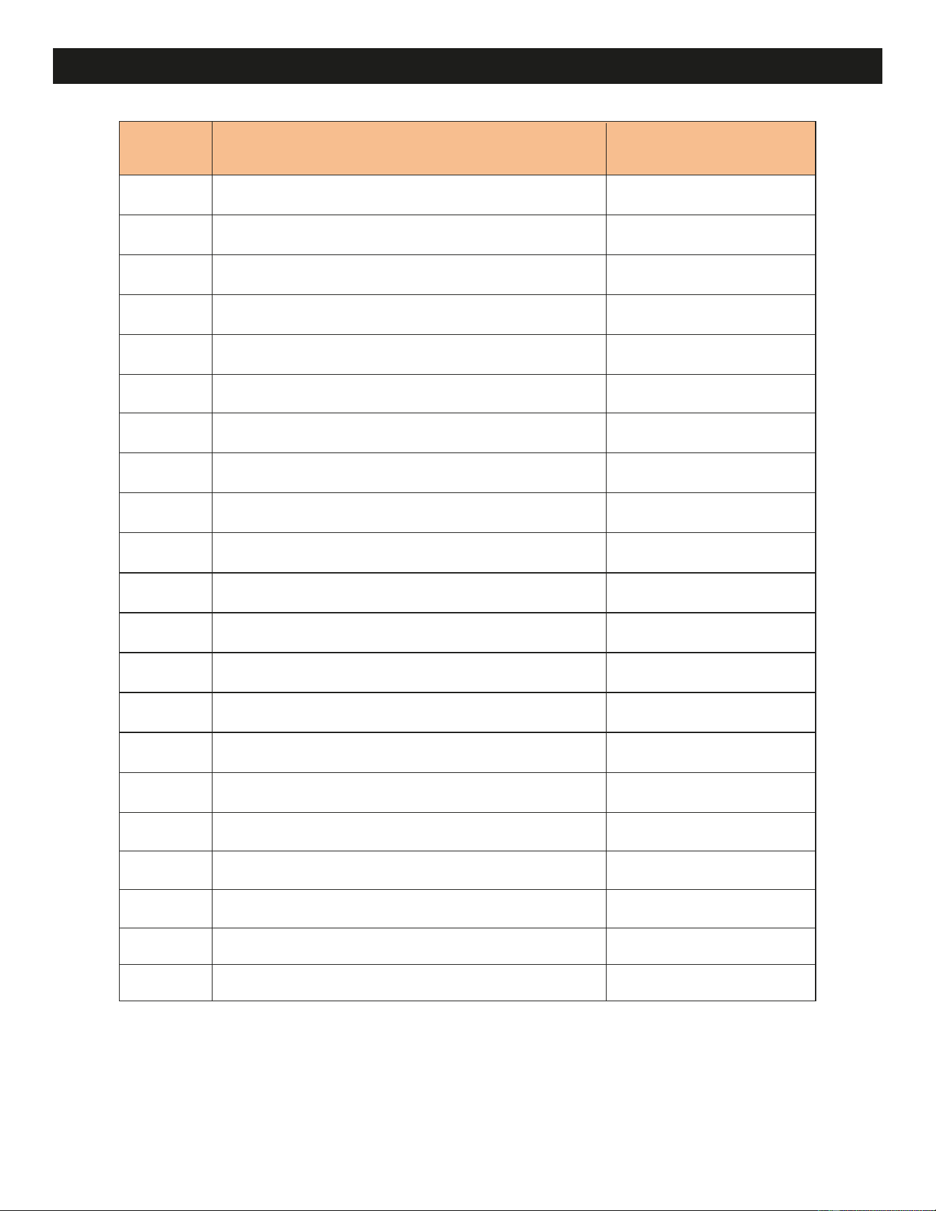
REF. SPARE PARTS, PART NUMBER NOVA 48
1
2
3
4
5
6
7
8
9
10
11
12
13
14
15
16
Heater Fan
Heater Core
Thermostat
Glass Face (Front/Back)
Side Glass
Log Set Front
Log Set Back
Ember Bed LED Section
Downlight LED Section
Touch Control Board
Main Power Switch
Power/Data (UART) Board
Wi-Fi Module
USB Thumb Drive
Main Control Board
Fireplace Remote Control
01-00238
01-00239
01-00240
04-00080
04-00081
05-00229
05-00267
01-00241
01-00243
01-00244
01-00328
01-00245
01-00246
01-00249
01-00250
01-00251
01-00255
13-00140
13-00127
01-00257
01-00252
Note: All warranty replacement parts are subject to approval by Modern Flames Technical
Support Team. Tracking information for the returned item may be required before a replacement
will be issued.
Power Supply
Film Assembly
Projection Assembly
Speakers
Projector Remote
17
18
19
20
21
(Special order for service
technicians only).
36
www.modernflames.com
ISED Statement
This device complies with Innovation, Science and Economic Development licence-exempt RSS
standard(s). Operation is subject to the following two conditions:
(1) this device may not cause interference; and
(2) this device must accept any interference. Including interference that may cause undesired
operation of the device.
Avis d’Industrie Canada
Le présent appareil est conforme aux Innovation, Science et développement économique aux
appareils radio exem pts de licence L'exploitation est autorisée aux deux conditions suivantes:
1) I'appareil ne doit pas produire de brouillage; et
2) I'utillsateur de I'appareil doit accepterbrouillage radioélectrique subi meme si le brouillage est
susceptible d'encompromettre le fonctionnement. mauvais fonctionnement de I'appareil.
CAN ICES-3 (B) / CAN NMB-3 (B)
For Fireplaces:
Radiation Exposure Statement:
This equipment complies with ISED radiation exposure limits set forth for an uncontrolled environment.
This equipment should be installed and operated with minimum distance 20cm between the radiator
& your body.
Déclaration d'exposition aux radiations:
Cet équipement est conforme aux limites d'exposition aux rayonnements ISED établies pour un
environnement non contrôlé. Cet équipement doit être installé et utilisé avec un minimum de 20 cm
de distance entre la source de rayonnement et votre corps.
For Remote:
Radiation Exposure Statement:
This product complies with the ISED RF exposure limit set forth for an uncontrolled environment and
is safe for intended operation as described in this manual.
Déclaration d'exposition aux radiations:
Ce produit est conforme à la limite d'exposition ISED RF définie pour un environnement non contrôlé
et est sûr pour le fonctionnement prévu comme décrit dans ce manuel.

For immediate help with installation, product information or if your product
arrives damaged, please call our toll-free number at:
(Monday – Friday, 8:00AM – 5:00PM, AZ Mountain Time)
OUR STAFF IS READY TO PROVIDE ASSISTANCE
Or email us at:
37
www.modernflames.com
07-00214
20260814
Copyright © 2026 RPG Brands (Modern Flames). All rights reserved. Products and specifications subject to change without
notice. The product images shown are for illustration purposes only and may not be an exact representation of the product.
DO NOT RETURN TO STORE
CALL US FIRST
1-877-246-9353
STOP