USE AND CARE GUIDE
THANK YOU
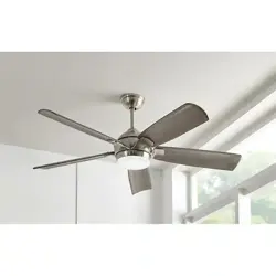
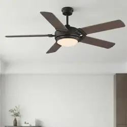
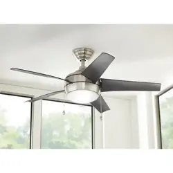
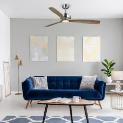
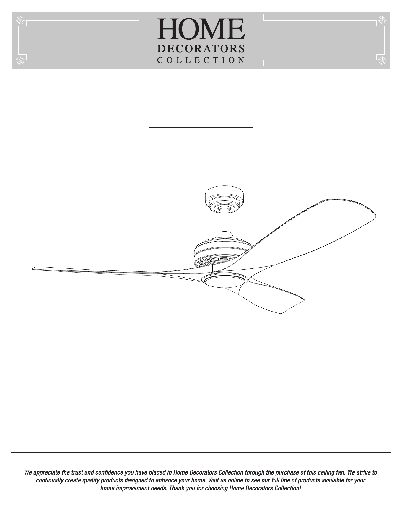
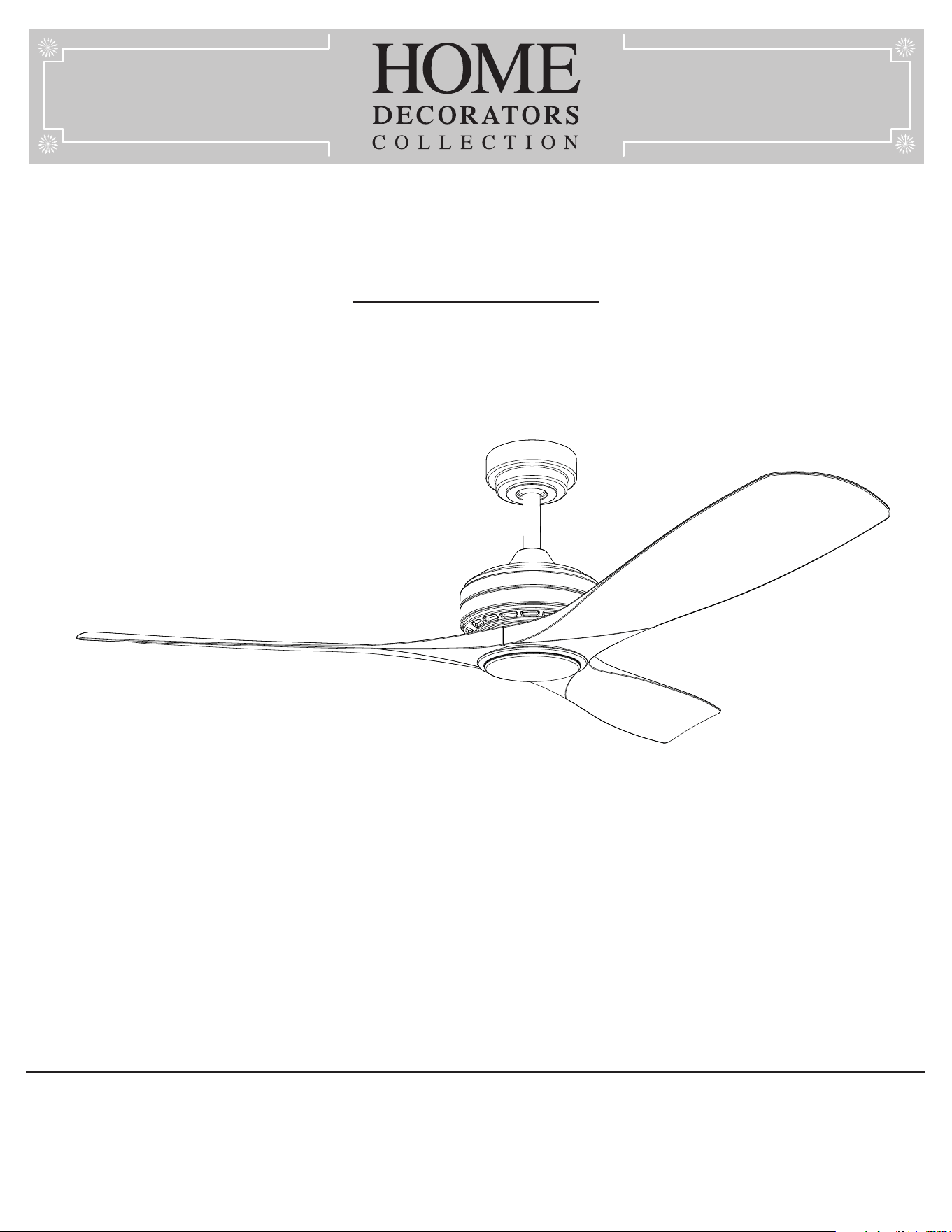
BAYSHIRE 52 INCH CEILING FAN
Questions, problems, missing parts? Before returning to the store,
call Home Decorators Collection Customer Service
8 a.m. - 7 p.m., EST, Monday-Friday, 9 a.m. - 6 p.m., EST, Saturday.
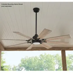
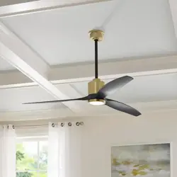
BAYSHIRE 60 INCH CEILING FAN
1-844-400-FANS (3267)
Item #1005 784 170
Item #1005 712 786
Item #1005 712 742
Item #1005 712 566
Item #1005 832 068
Item #1005 712 578
Item #1005 712 813
Item #1005 712 652
Model #102L52MBKDDW
Model #102L52MBKDB
Model #102L52BNDDW
Model #102L52BNLDW
Model #102L60MBKDDW
Model #102L60MBKDB
Model #102L60BNDDW
Model #102L60BNLDW
HOMEDEPOT.COM/HOMEDECORATORS
2
Installation .....................................................................
Table of Contents ..........................................................2
Safety Information .........................................................2
Warranty .........................................................................3
Pre-installation .............................................................. 3
6
Assembly ....................................................................... 7
Table of Contents
13Operation
Care and Cleaning 15
Troubleshooting 16
FCC Statement 17
......................................................................
.......................................................
...........................................................
............................................................
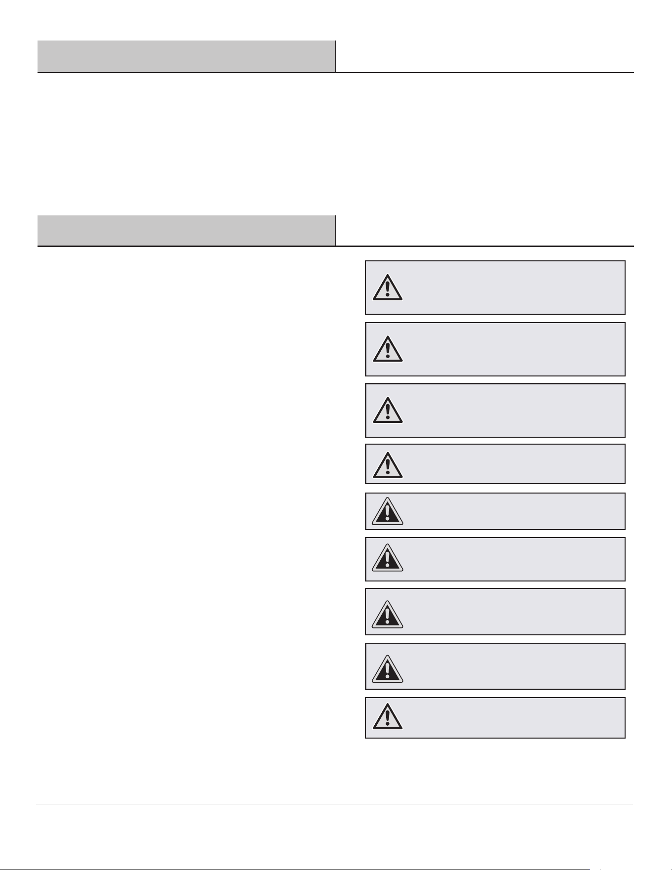
Safety Information
1.
2.
3.
4
.
5.
6.
7
.
READ AND SAVE THESE INSTRUCTIONS
WARNING:
WARNING:
WARNING:
CAUTION:
CAUTION:
CAUTION:
CAUTION:
WARNING:
WARNING:
To reduce the risk of electric shock, ensure electricity has
been turned off at the circuit breaker or fuse box before you
begin.
All wiring must be in accordance with the National Electrical
Code “ANSI/NFPA 70” and local electrical codes.
Electrical installation should be performed by a qualified
licensed electrician.
The outlet box and support structure must be securely
mounted and capable of reliably supporting a minimum of 35
lbs (15.9 kg). Use only UL Listed outlet boxes marked
“Acceptable for Fan Support of 35 lbs. (15.9 kg) or less.”
Do not place objects in the path of the blades.
Do not use water or detergents when cleaning the fan or fan
blades. A dry dust cloth or lightly dampened cloth will be
suitable for most cleaning.
After making electrical connections, spliced conductors
should be turned upward and pushed carefully up into the
outlet box. The wires should be spread apart with the
grounded conductor and the equipment-grounding conductor
on one side of the outlet box and ungrounded conductor on
the other side of the outlet box.
All setscrews must be checked and retightened where
necessary before installation.
To reduce the risk of personal injury, do not
bend the blade brakcets when installing the brackets,
balancing the blades, or cleaning the fan. Do not insert
foreign objects in between rotating fan blades.
The fan must be mounted with a minimum
of 7 ft (2.1 m) clearance from the trailing edge of the
blades to the floor.
Changes or modifications not expressly
approved by the party responsible for compliance could
void the user’s authority to operate the equipment.
To reduce the risk of electrical shock or fire,
do not use this fan with any solid-state fan speed con-
trol device. It will permanently damage the electronic
circuitry.
To reduce the risk of electrical shock, this
must be installed with an lsolating wall control/switch.
To reduce the risk of fire, electric shock
or personal injury, mount to outlet box marked
“acceptable for fan support of 35 lbs. (15.9kg)
or less” and use screws provided with the outlet box.
To avoid possible electrical shock,
turn the electricity off at the main fuse box before
wiring.
To reduce the risk of personal injury,
use only the screws provided with the outlet box.
To avoid personal injury or damage to the fan
and other items, use caution when working around or
cleaning the fan.
Suitable for use in wet locations when installed in a GFCI
protected branch circuit.
8.
Use only with light kits marked “Suitable for use in wet locations”.
9.
3
Warranty
Pre-InstallationPre-Installation
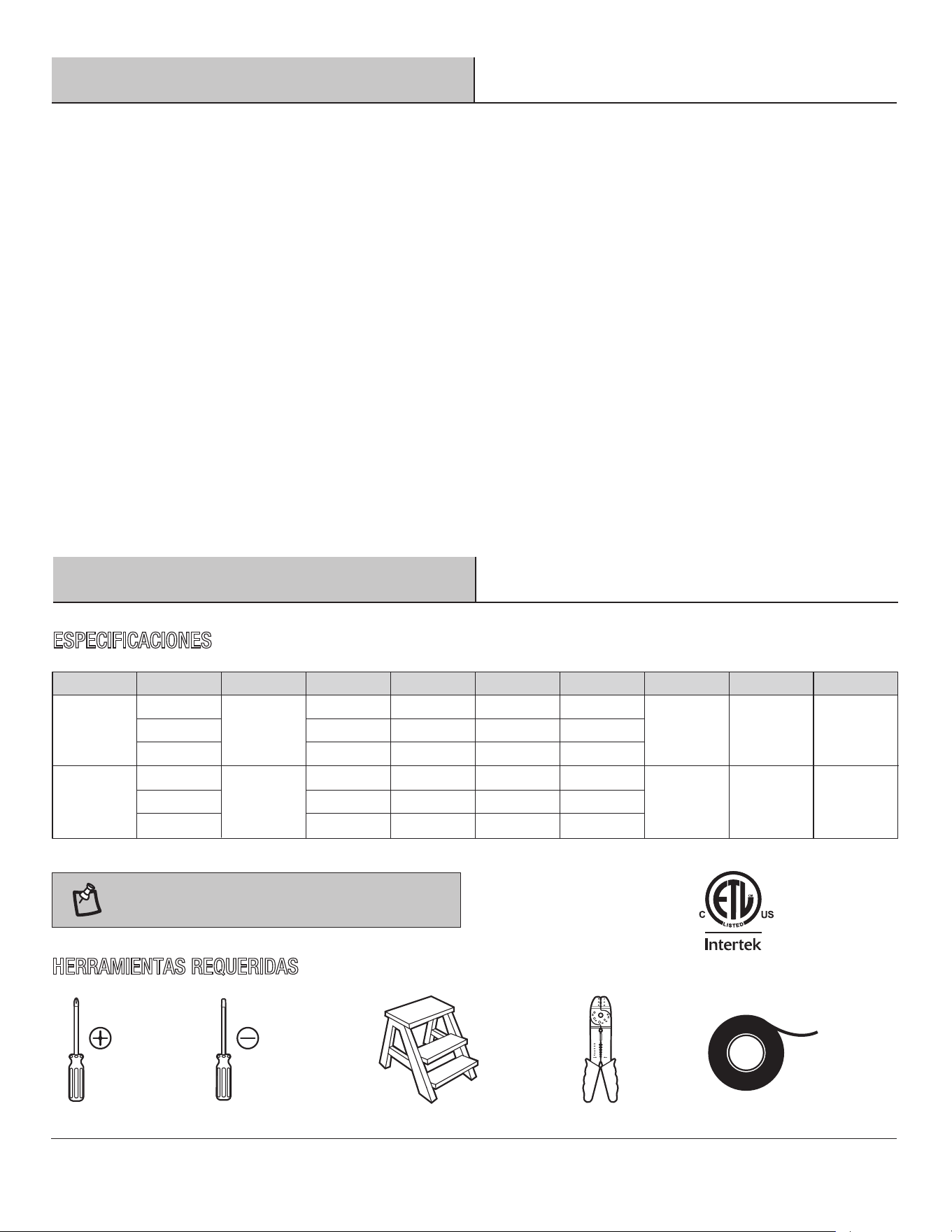
TOOLS REQUIRED
Phillips
screwdriver
Electrical
tape
Wire
stripper
Flat blade
screwdriver
Step
ladder
NOTE:
52 in.
LOW
MED
HIGH
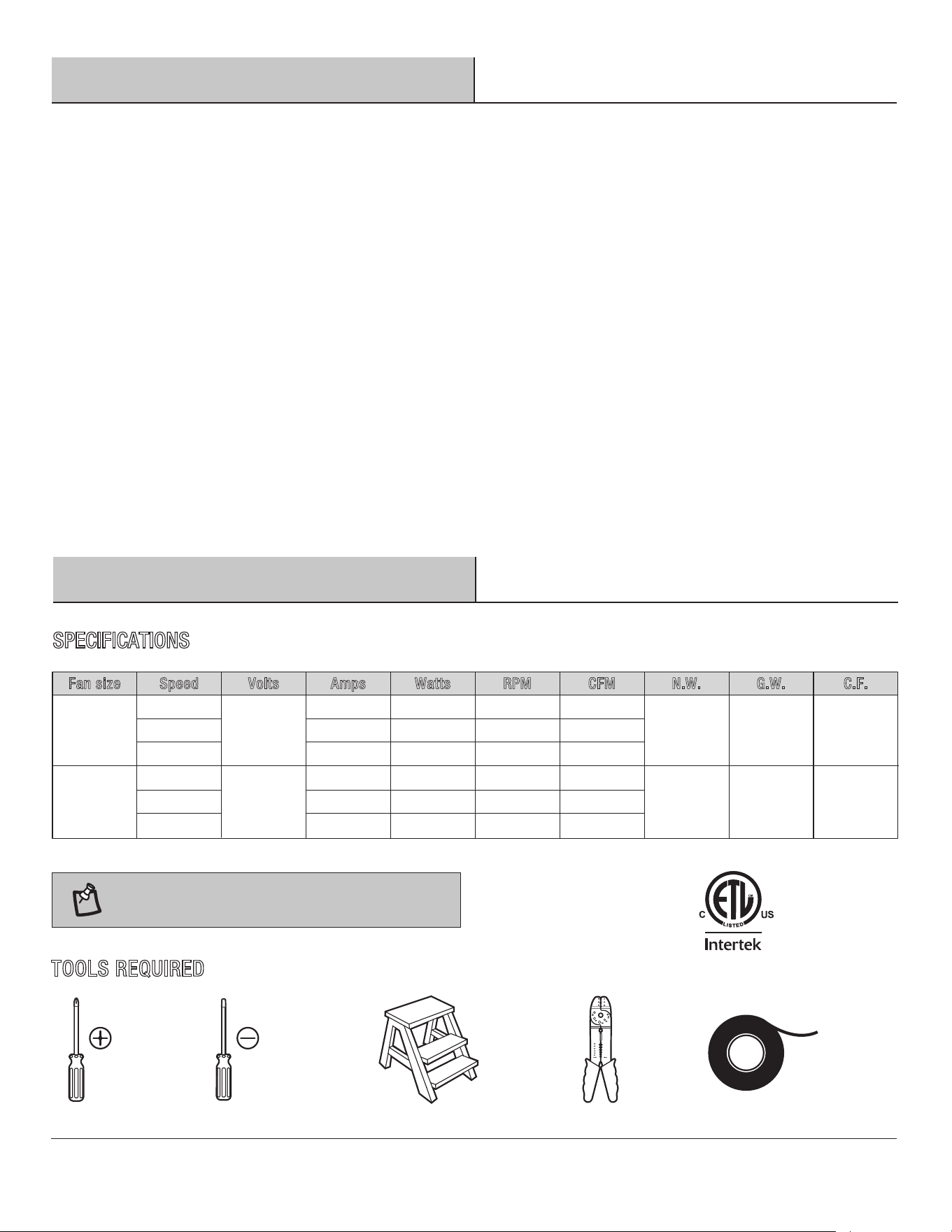
120
Fan
size Watts RPM CFMSpeed Volts Amps
N.
W. G.W. C.F.
60 in.
LOW
MED
HIGH
120
1.53 cu ft.
0.08 2.69 70 2527
0.21 15.00 130 5069
0.49 32.62 170 6411
5.39 kgs
(11.89 lbs)
7.82 kgs
(17.24 lbs)
1.84 cu ft.
0.08 2.32 55 2740
0.15 9.80 100 5440
0.39 24.33 130 6837
6.06 kgs
(13.35 lbs)
8.80 kgs
(19.40 lbs)
We warrant the fan motor to be free from defects in workmanship and material present at time of shipment from the factory for a period
of lifetime after the date of purchase by the original purchaser. We also warrant the light kit, to be free from defects in workmanship and
material present at time of shipment from the factory for a period of five years after the date of purchase by the original purchaser,
excluding any glass or acrylic components and wooden blades, to be free from defects in workmanship and material at the time of ship-
ment from the factory for a period of two years after the date of purchase by the original purchaser. We agree to correct such defects
without charge or at our option replace with a comparable or superior model if the product is returned. To obtain warranty service, you
must present a copy of the receipt as proof of purchase. All costs of removing and reinstalling the product are your responsibility. Damage
to any part such as by accident, misuse, improper installation or by affixing any accessories, is not covered by this warranty. Because of
varying climatic conditions this warranty does not cover any changes in brass finish, including rusting, pitting, corroding, tarnishing or
peeling. Brass finishes of this type give their longest useful life when protected from varying weather conditions. A certain amount of
“wobble” is normal and should not be considered a defect. Servicing performed by unauthorized persons shall render the warranty invalid.
There is no other express warranty. We hereby disclaim any and all warranties, including but not limited to those of merchantability and
fitness for a particular purpose to the extent permitted by law. The duration of any implied warranty which cannot be disclaimed is limited
to the time period as specified in the express warranty. Some states do not allow limitation on how long an implied warranty lasts, so the
above limitation may not apply to you. The retailer shall not be liable for incidental, consequential, or special damages arising out of or in
connection with product use or performance except as may otherwise be accorded by law. Some states do not allow the exclusion of
incidental or consequential damages, so the above exclusion or limitation may not apply to you. This warranty gives specific legal rights,
and you may also have other rights which vary from state to state. This warranty supersedes all prior warranties. Shipping costs for any
return of product as part of a claim on the warranty must be paid by the customer.
Contact the Customer Service Team at 1-844-400-FANS (or 3267) or visit visit www.HOMEDEPOT.COM/HOMEDECORATORS
Please contact 1-844-400-FANS (3267) for further assistance.
HOMEDEPOT.COM/HOMEDECORATORS
SPECIFICATIONS
These are approximate measures. They do not
include amps and wattage used by the light kit.
4
AA
BB
CC
DD
EE
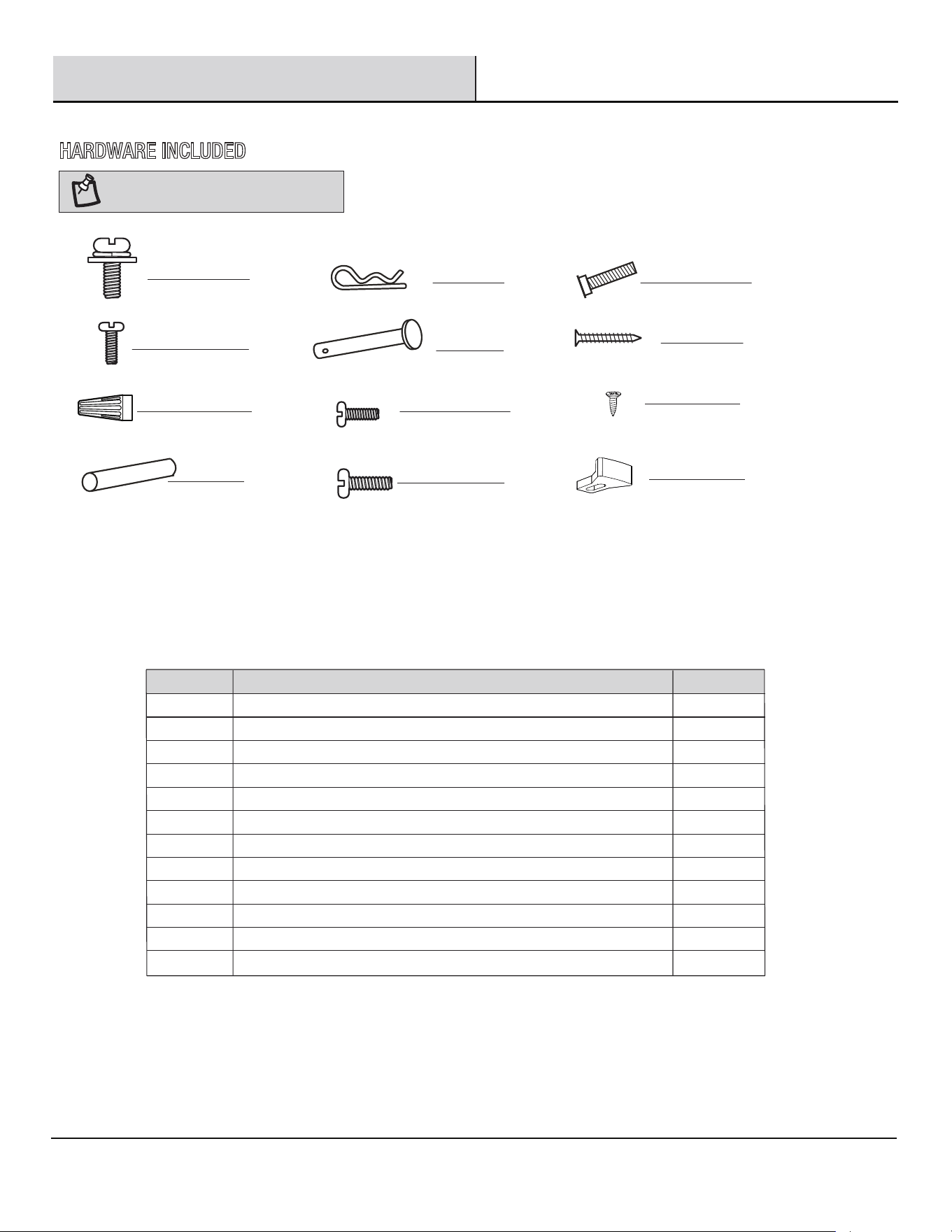
Blade screw
Description
7
FF
GG
HH
Light kit screw (preassembled)
3
Cross pin (not to scale) (preassembled)
Hitch pin (preassembled)
1
1
2
2
2
1
Hanger ball set screw (preassembled)
Fan motor assembly coupling set screw (preassembled)
Mounting bracket screw (preassembled)
Lock pin (not to scale) (preassembled)
Remote control holder mounting screws
II
JJ
KK
NOTE:
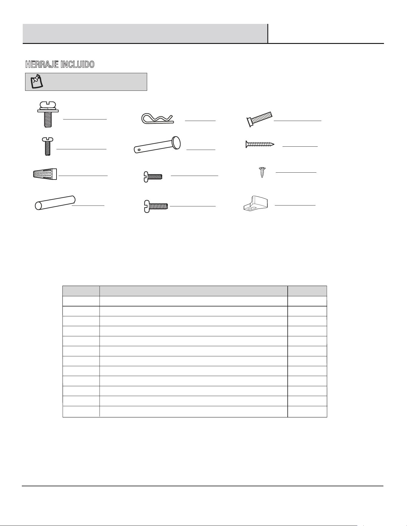
Hardware shown to actual size
AA
EE
FF
GG
HH
II
BB
CC
DD
JJ
1
1
Part
Wire nuts
PACKAGE CONTENTS
Remote battery cover screw
Quantity
KK
Pre-Installation (continued)
3
HARDWARE INCLUDED
6LL
Plastic block (preassembled)
LL
5
Pre-Installation (continued)
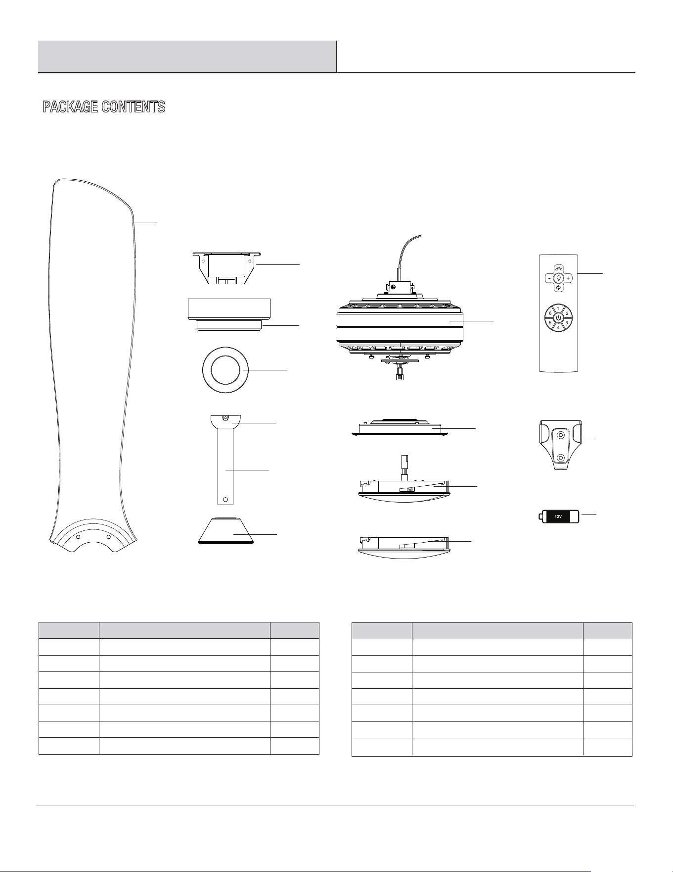
PACKAGE CONTENTS
Fan motor assembly
Light kit assembly
J
K
Part QuantityDescription
M
L
Light kit cover
1
1
1
1
Remote control holder
Remote control
12V Battery
Blade
Mounting bracket
3
B
C
D
Part
A
QuantityDescription
F
E
Canopy
1
1
1
1
Hanger ball (preassembled)
Canopy cover
G
H
N
O
Downrod (preassembled)
Coupling cover
Light kit plate
1
1
1
1
1
M
N
O
A
B
C
D
E
F
G
H
J
Please contact 1-844-400-FANS (3267) for further assistance.
HOMEDEPOT.COM/HOMEDECORATORS
K
L
6
Installation
WARNING:
1
1
1
3
2
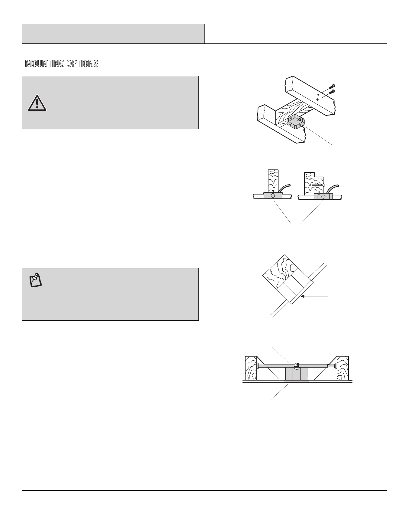
If your ceiling fan does not have an existing UL-listed
mounting box, then install one using the following instructions:
□ Disconnect the power by removing the fuses or turning
off the circuit breakers.
□
□
Secure the outlet box (1) (not included) directly to the
building structure. Use appropriate fasteners and
materials (not included). The outlet box and its bracing
must be able to fully support the weight of the moving
fan (at least 35 lbs.). Do not use a plastic outlet box.
The illustrations to the right show three different ways to
mount the outlet box (not included).
□
To hang your fan where there is an existing fixture but no
ceiling joist, you may need an installation hanger bar (3)
(not included), as shown.
NOTE:
To reduce the risk of fire, electric shock, or
personal injury, mount the fan to an outlet box marked
acceptable for fan support. An outlet box commonly used for
the support of lighting fixtures may not be acceptable for fan
support and may need to be replaced. If in doubt, consult a
qualified electrician.
You may need a longer downrod to maintain proper
blade clearance when installing on a steep, sloped ceiling.
The maximum angle allowable is 18°. If the canopy touches
the downrod, remove the decorative canopy bottom cover
and turn the canopy 180° before attaching the canopy to the
mounting plate (2).
MOUNTING OPTIONS
7
Assembly — Hanging the Fan
□
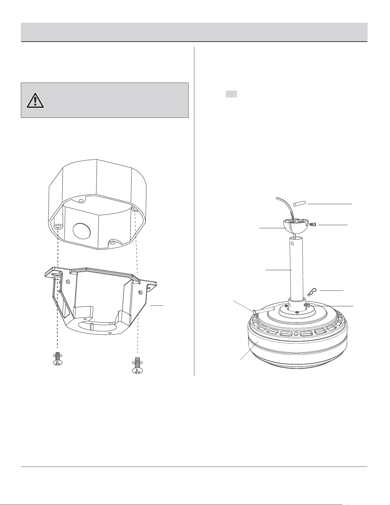
Loosen the two fan motor assembly coupling set screws
(HH) from the fan motor assembly (H) coupling.
□
□
Remove the hitch pin (EE) and lock pin (FF) from the
downrod (F). Remove the hanger ball (E) from the
downrod (F) by loosening the hanger ball set screw
(GG), and removing the cross pin (DD), then sliding
the hanger ball (E) off of the downrod (F).
Attaching the downrod to the
fan motor assembly
2
Carefully feed the fan wires up through the downrod (F).
Thread the downrod (F) into the fan motor assembly (H)
coupling. Line up the holes and replace the lock pin (FF)
and the hitch pin (EE). Tighten the set screws (HH).
1
Attaching the mounting bracket to
the electrical box
□
Secure the mounting bracket (B) to the ceiling outlet box
with the screws and washers provided with your outlet
box.
WARNING:
B
DD
GG
E
F
FF
EE
HH
H
Please contact 1-844-400-FANS (3267) for further assistance.
HOMEDEPOT.COM/HOMEDECORATORS
To reduce the risk of fire, electric shock, or
other personal injury, mount the fan only to an outlet box or
supporting system marked acceptable for fan support and
use the mounting screws provided with the outlet box.
8
3
Attaching the coupling cover, and
canopy to the downrod
Assembly — Hanging the Fan (continued)
□
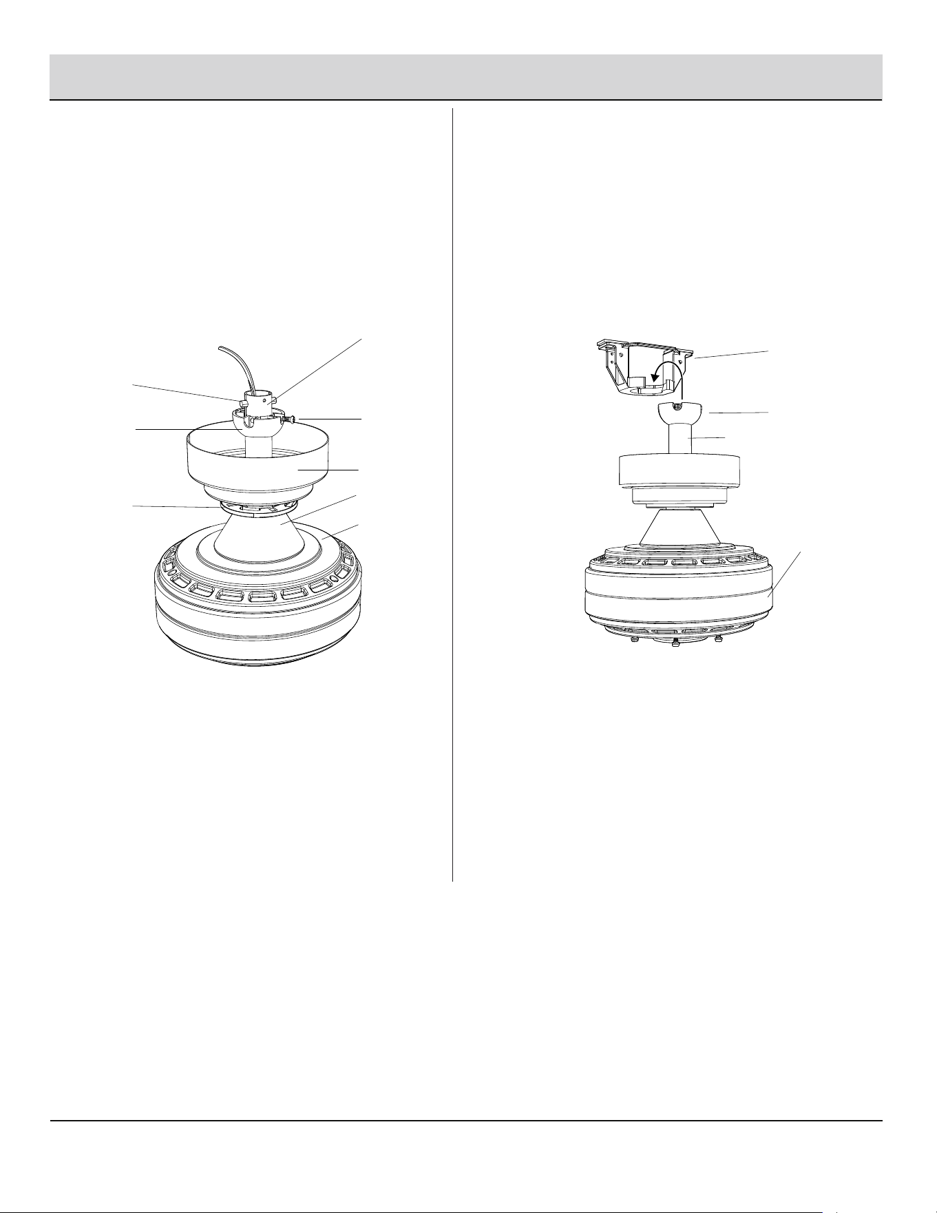
Slip the coupling cover (G), canopy cover (D) and
canopy (C) onto the downrod (F). Carefully reinstall the
hanger ball (E) onto the downrod (F), and ensure that
the cross pin (DD) is in the correct position, the hanger
ball set screws (GG) are tight, and the wires are not
twisted.
4
Hanging the fan motor assembly
from the mounting bracket
□
Lift the fan motor assembly (H) into position, and place
the hanger ball (E) into the mounting bracket (B). Rotate
the fan motor assembly (H) until the check groove drops
into the registration slot and seats firmly. The downrod (F)
should not rotate if this is done correctly.
F
DD
GG
E
C
G
H
D
B
E
F
H
9
Assembly — Hanging the Fan (continued)
5
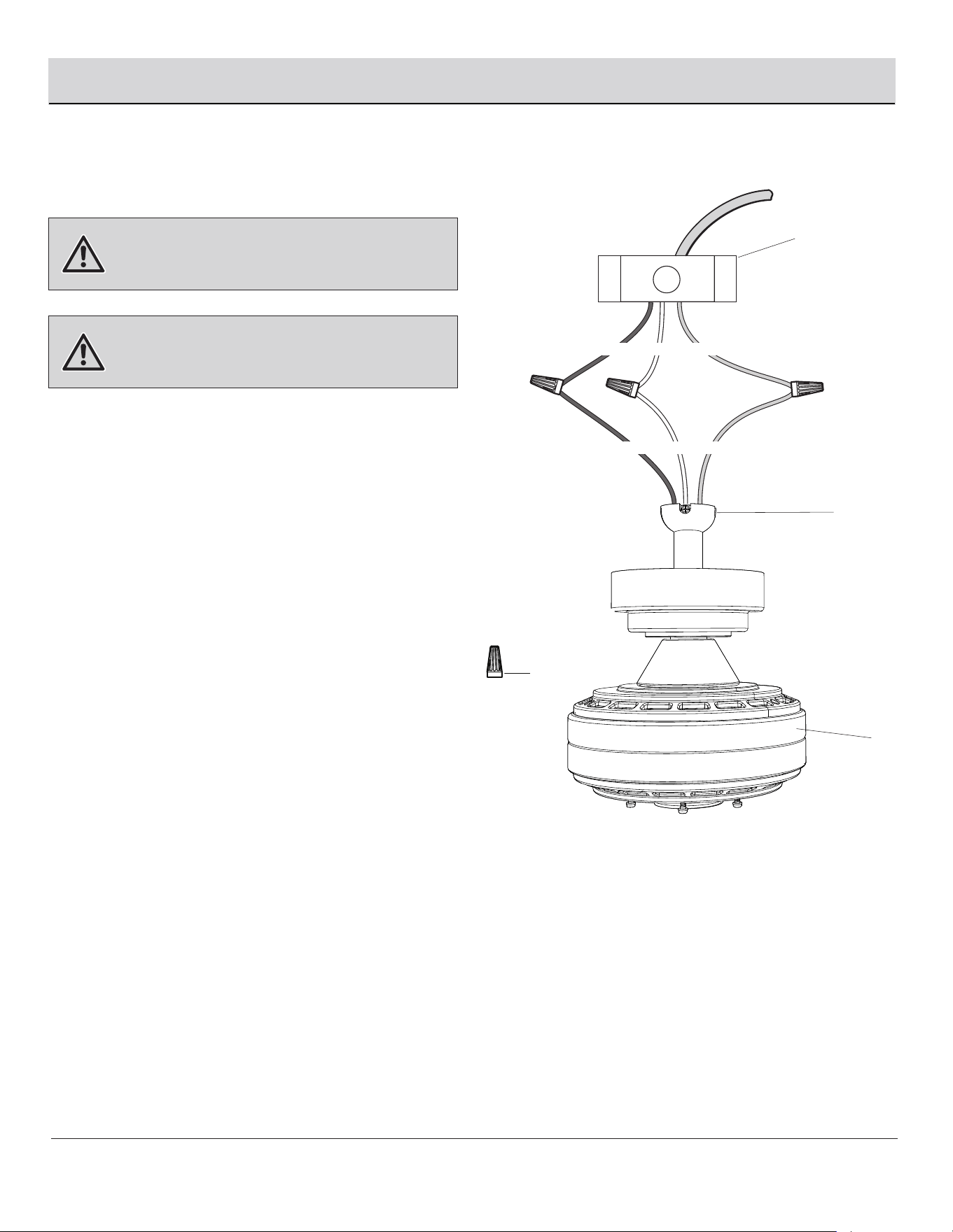
Making the electrical connections
WARNING:
WARNING:
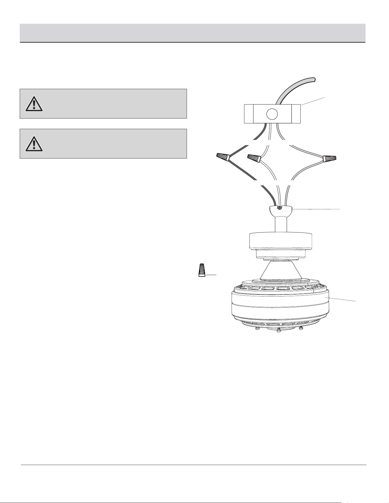
Follow the steps below to connect the fan to your house
supply wires. Secure the wire nuts (CC) supplied with your
fan by wrapping the connections with electrical tape.
□ Connect the black (hot) wire from the ceiling to the
black wire from the fan motor assembly (H).
□ Connect the white (neutral) wire from the ceiling to
the white wire from the fan motor assembly (H).
□ If your outlet box (1) has a ground wire (green or bare
copper), connect it to the fan ground wires; otherwise,
connect the hanger ball (E) ground wire to the
mounting bracket (B).
□ Secure the wire connection with a plastic wire nut
(CC) provided with the electrical hardware.
□ After connecting the wires, spread them apart so that
the green and white wires are on one side of the
outlet box (1) and the black wires are on the other side.
Carefully tuck the wire connections up into the outlet
box (1).
CC (x3)
1
H
Black White Green
Black White Green
E
Please contact 1-844-400-FANS (3267) for further assistance.
HOMEDEPOT.COM/HOMEDECORATORS
To avoid possible electrical shock, ensure the
electricity is turned off at the circuit breaker or main fuse box
before wiring.
Check to see that all connections are tight,
including the ground, and that no bare wire is visible at the
wire nuts, except for the ground wire.
J
J
F
10
6
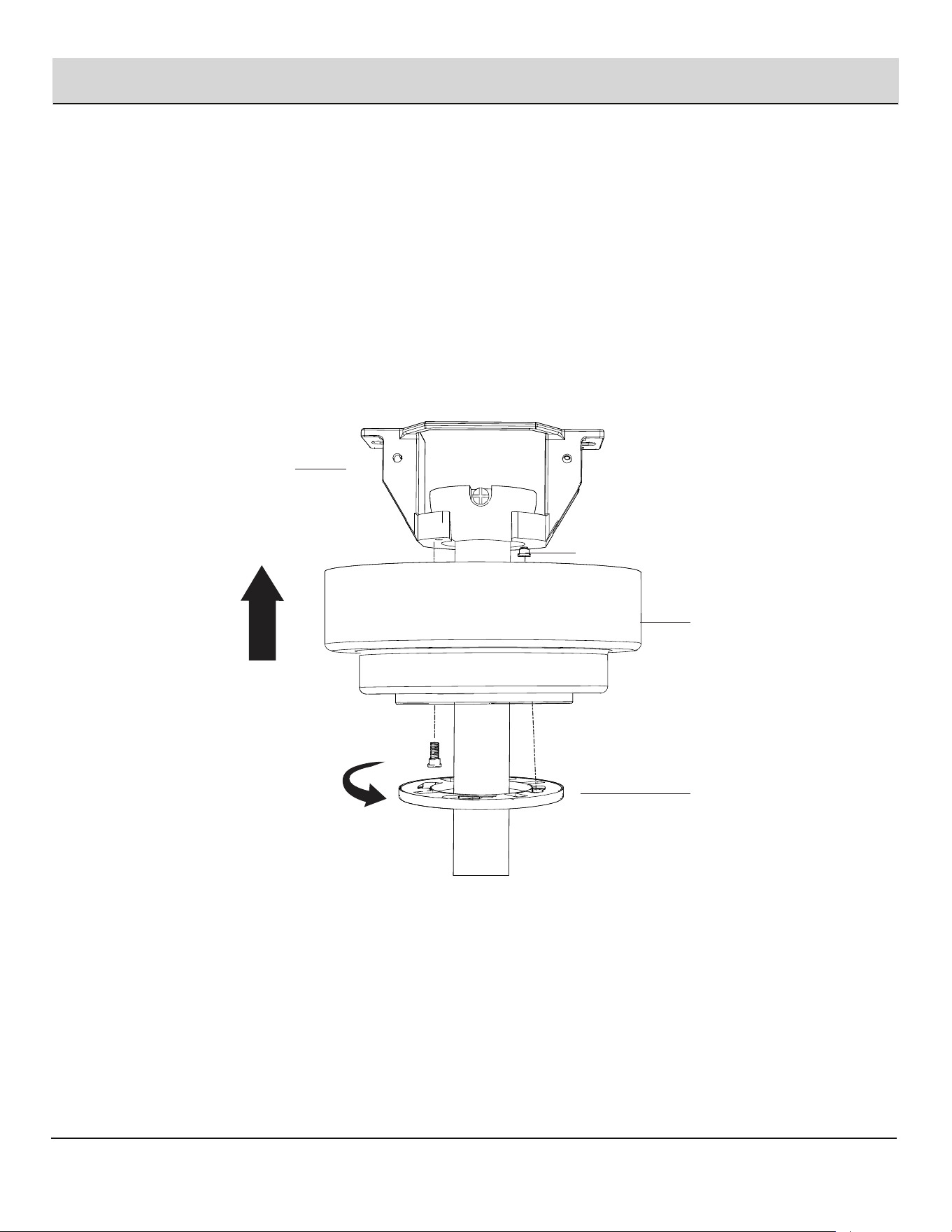
Securing the fan motor assembly to the mounting bracket
□
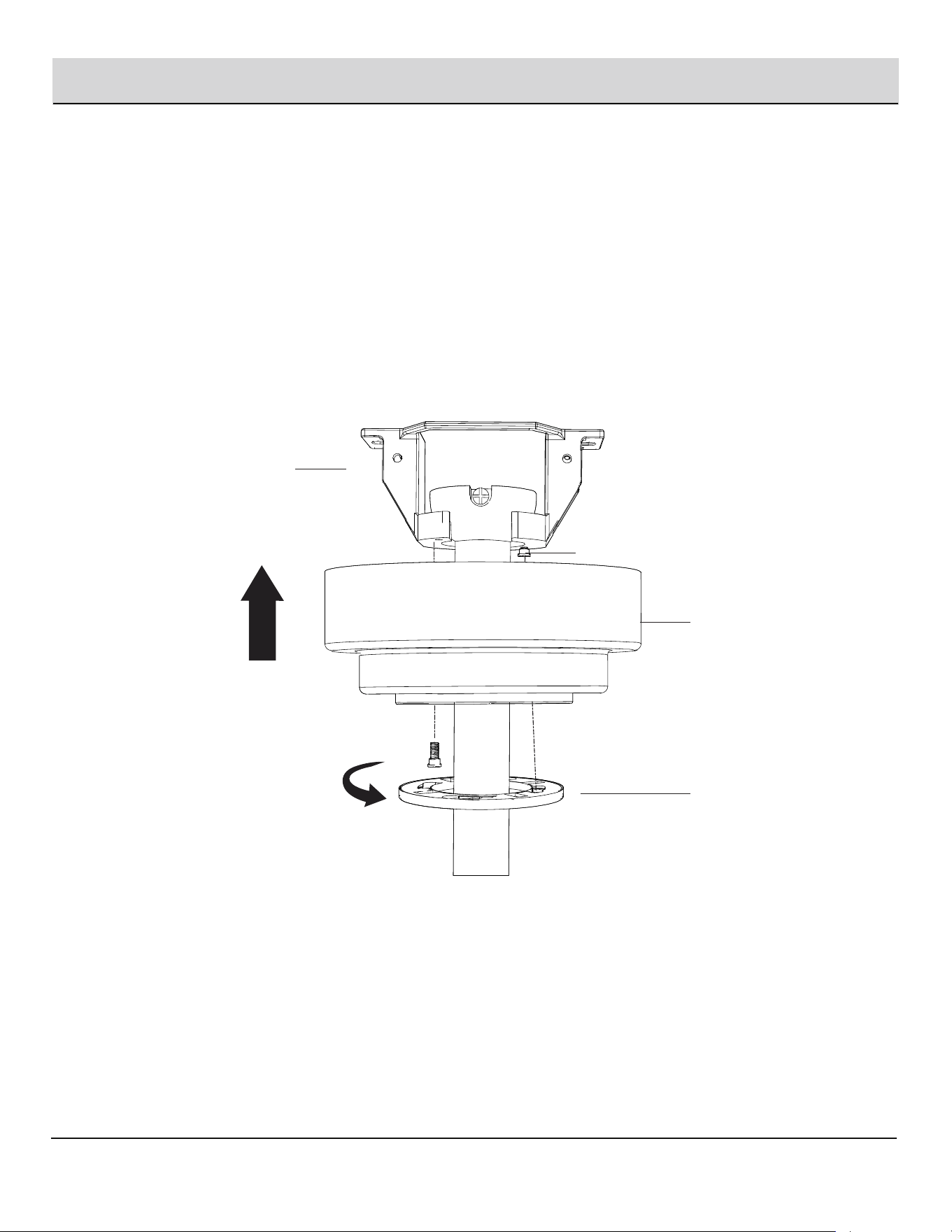
Remove two mounting bracket screws (II) from the mounting bracket (B).
□
Attach the canopy (C) to the mounting bracket (B) by using the two mounting bracket screws (II) previously removed.
□
Tighten the mounting bracket screws (II) .
Assembly — Hanging the Fan (continued)
□ Align the oval shape on the canopy (C) with canopy cover (D). Push up the canopy cover (D) until the screw (II) heads engage
to the slots on the canopy cover (D), and rotate the canopy cover (D) until it is attached to the bottom of the canopy (C) properly.
II
C
D
B
□
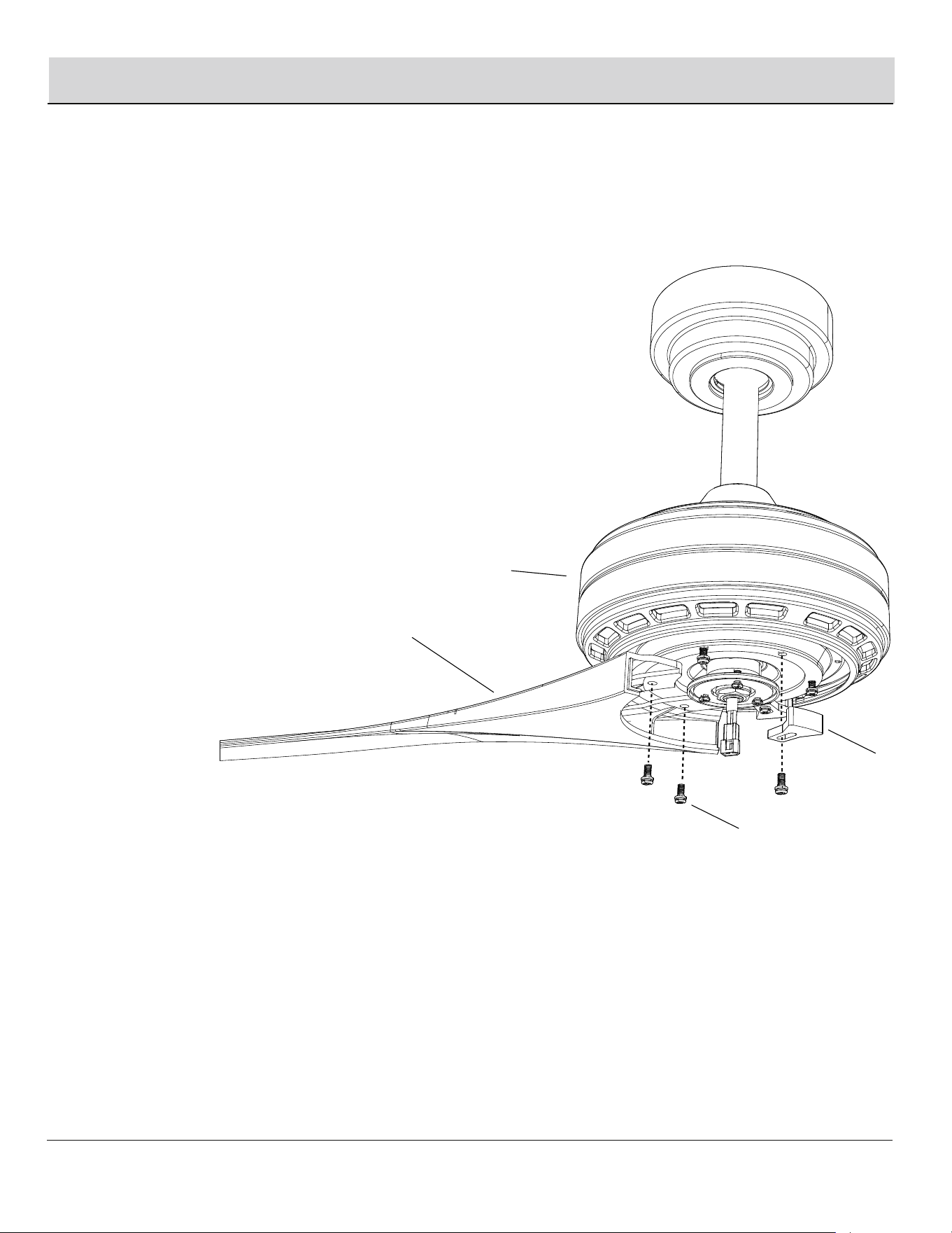
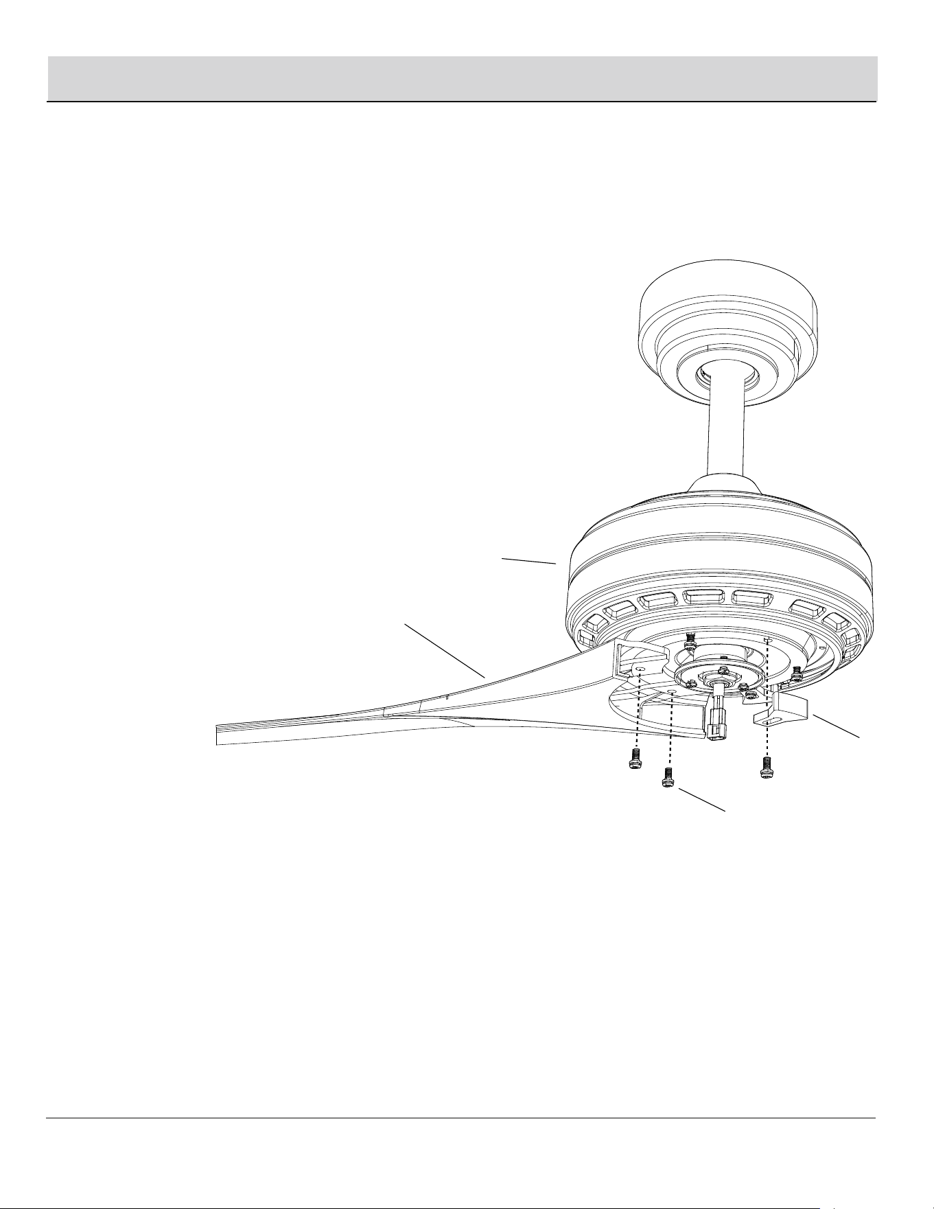
Fasten fan blades (A) to the fan motor assembly (H) one by one.
Please secure the blade holder screws (AA) one by one.
Please contact 1-844-400-FANS (3267) for further assistance.
HOMEDEPOT.COM/HOMEDECORATORS
□
Fastening the blades
to the fan motor assembly
7
Assembly — Attaching the Fan Blade
Remove the six blade screws (AA) and six plastic blocks (LL)
from the fan motor assembly (H).
11
H
A
AA
LL
12
Assembly — Installing the Light Kit
□
Fastening the light kit plate and light kit
assembly to the fan motor assembly
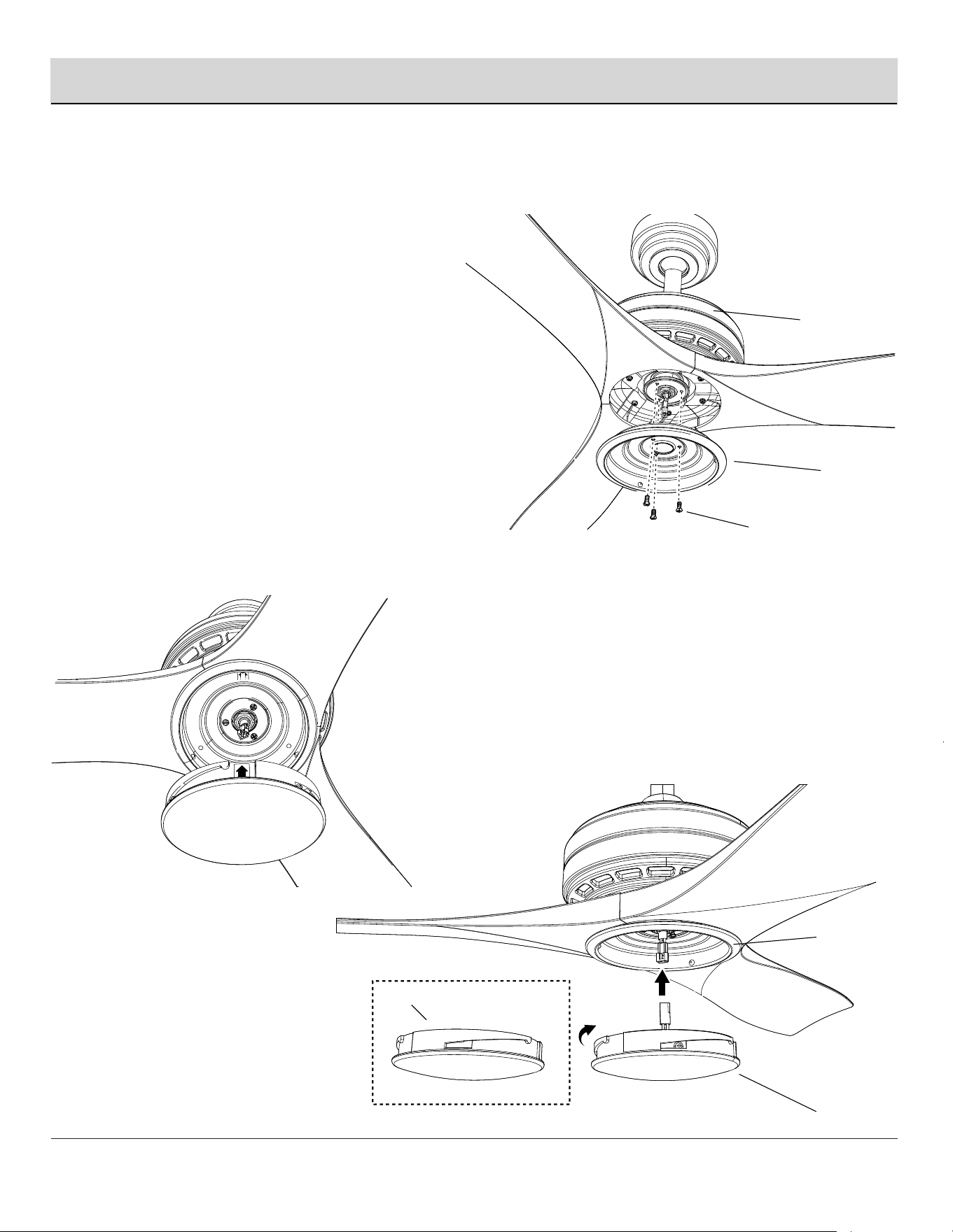
8
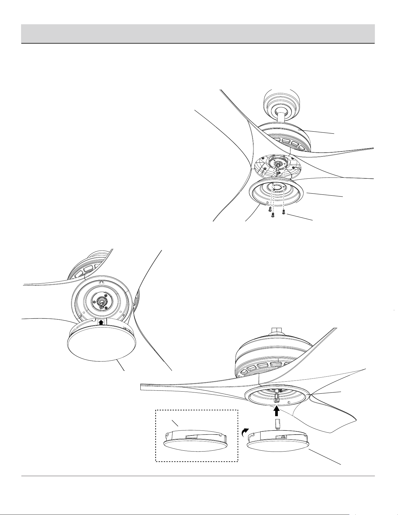
Remove three preassembled light kit screws (BB)
on the fan motor assembly (H).
BB
J
□
Attach the light kit plate (J) to the fan motor
assembly (H). Tighten light kit screws (BB) securely.
H
J
L
K
□
Connect the light lead wire, align the two arrow
marks on light kit plate (J) and light kit assembly (K),
attach the light kit assembly (K) onto light kit plate (J)
by twisting left tightly.
□
Optional: attach the light kit cover (L) onto the light kit
plate (J) by twisting left tightly if light kit assembly (K)
is not preferable.
REMOTE CONTROL OPERATING INSTRUCTIONS
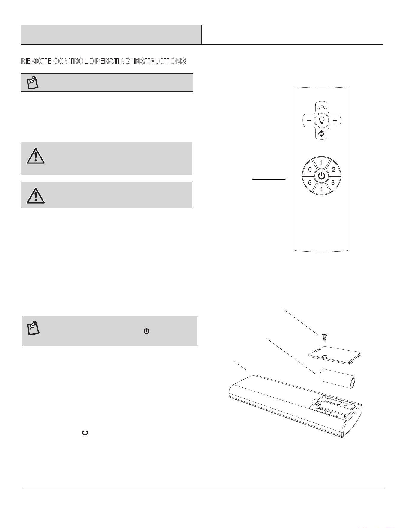
Install a 12V battery (O) into the remote control (M). Fasten the battery
cover screw (KK) after installation. To prevent damage to the remote
control, remove the battery if not used for long periods of time.
13
Operation
WARNING:
WARNING:
NOTE:
Should you desire to install more than one fan in the home, please
install one by one using the steps below to insure one remote
operates each fan independently:
□ Step 1: Turn off the main power source to all fans to begin
the learning process on any single fan.
□
Step 2: Restore power to only one fan at a time for pairing, the
rest remain off by use of your wall mounted power switch.
Step 3: Within 30 seconds of turning the fan’s AC power ON,
press and hold the button for 5 seconds to enter the learning
function. Once the receiver has detected the set frequency, a
beeping sound is emitted when pairing is complete.
□
M
KK
O
M
Please contact 1-844-400-FANS (3267) for further assistance.
HOMEDEPOT.COM/HOMEDECORATORS
Do not short-circuit, disassemble, heat up,
connect improperly, or dispose of used batteries in fire. Do
not recharge or mix batteries with used or other battery
types. Immediately remove used batteries.
a)The cells shall be disposed of properly,
including keeping them away from children; and
b) Even used cells may cause injury.
LEARNING/PAIRING PROCESS FOR
MULTIPLE FAN INSTALLATION
After the AC power is on, do not press any other button
on the remote control before pressing the (FAN ON/OFF)
button. Doing so will cause the procedure to fail.
NOTE:
Your new fan is already programmed with a unique
code to be operated with the included handheld remote.
□ Step 4: Repeat steps 1, 2 and 3 with each individual fan to
insure one remote does not operate multiple fans.
14
Operation (continued)
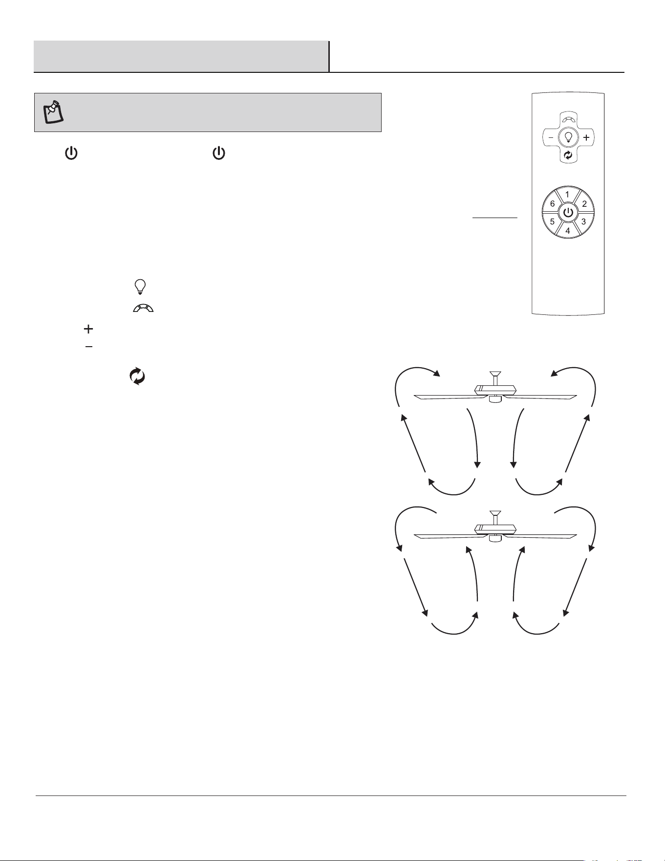
1. Fan button. - Press and release the button to turn the fan on or off.
2. Speed functions
Number 1/ 2/ 3/ 4/ 5/ 6, speed button
Press and release button one time will change the speed of the fan.
□
Fan off. The fan memory function will store the current setting for the next time the fan is in use.
□
(Counterclockwise Direction) A downward air flow creates a
cooling effect. This allows you to set your air conditioner on a
higher setting without affecting your comfort.
(Clockwise Direction) An upward air flow moves warm air off the
ceiling. This allows you to set your heating unit on a lower setting
without affecting your comfort.
4. Fan reverse button (Must be Pushed when the fan is in operation)
□
□
3. Light functions
□ Press and release button one time will turn the light on or off.
□
Press to increase the desired light level.
□
Press to decrease the desired light level.
M
NOTE:
□ Press and release button to select the desired color temperature.
On start up your ceiling fan will oscillate back and forth. This is NORMAL
OPERATION for DC ceiling fan as it goes through its calibration cycle. The fan is
NOT DEFECTIVE.
15
Operation (continued)
Care and Cleaning
□ Check the support connections, brackets, and blade
attachments twice a year. Ensure they are secure.
Because of the fan’s natural movement, some
connections may become loose over time. It is not
necessary to remove the fan from the ceiling.
□ Clean your fan periodically. Use only a soft brush or
lint-free cloth to avoid scratching the finish. The plating is
sealed with a lacquer to minimize discoloration or
tarnishing.
□ (Optional) Apply a light coat of furniture polish to the wood
blades.
□ (Optional) Cover small scratches with a light application of
shoe polish.
Do
□ Do not use water when cleaning. Water could damage the
motor, or the wood, or possibly cause an electrical shock.
□ Do not apply oil to your fan or motor. The motor has
permanently-lubricated sealed ball bearings.
Do not
□
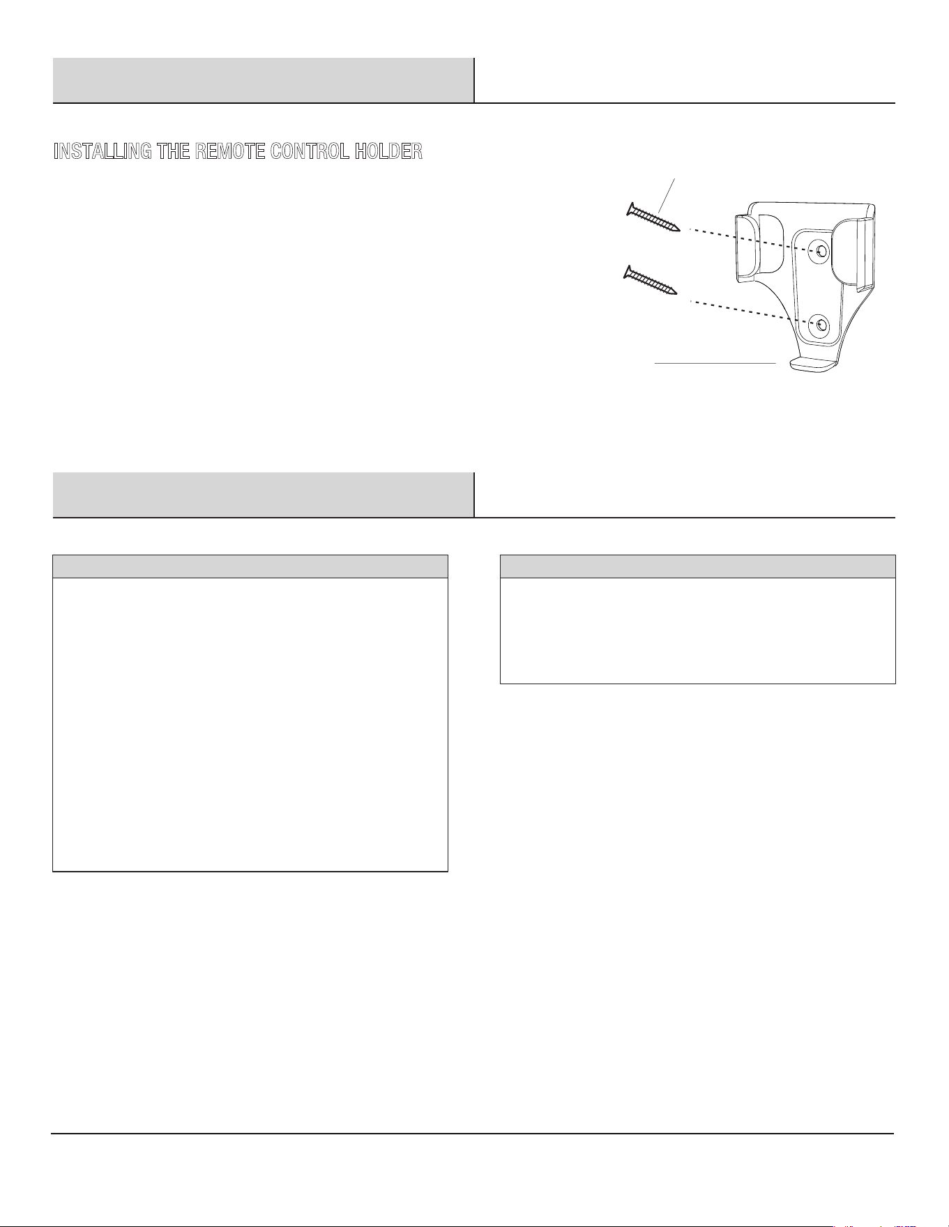
Attach the remote control holder (N) with the two remote control
holder mounting screws (JJ).
INSTALLING THE REMOTE CONTROL HOLDER
JJ
N
Please contact 1-844-400-FANS (3267) for further assistance.
HOMEDEPOT.COM/HOMEDECORATORS
16
Troubleshooting
WARNING:
17
Ensure the power is off at the electrical
panel box before you attempt any repairs. Refer to the section
“Making the Electrical Connections” on page 9.
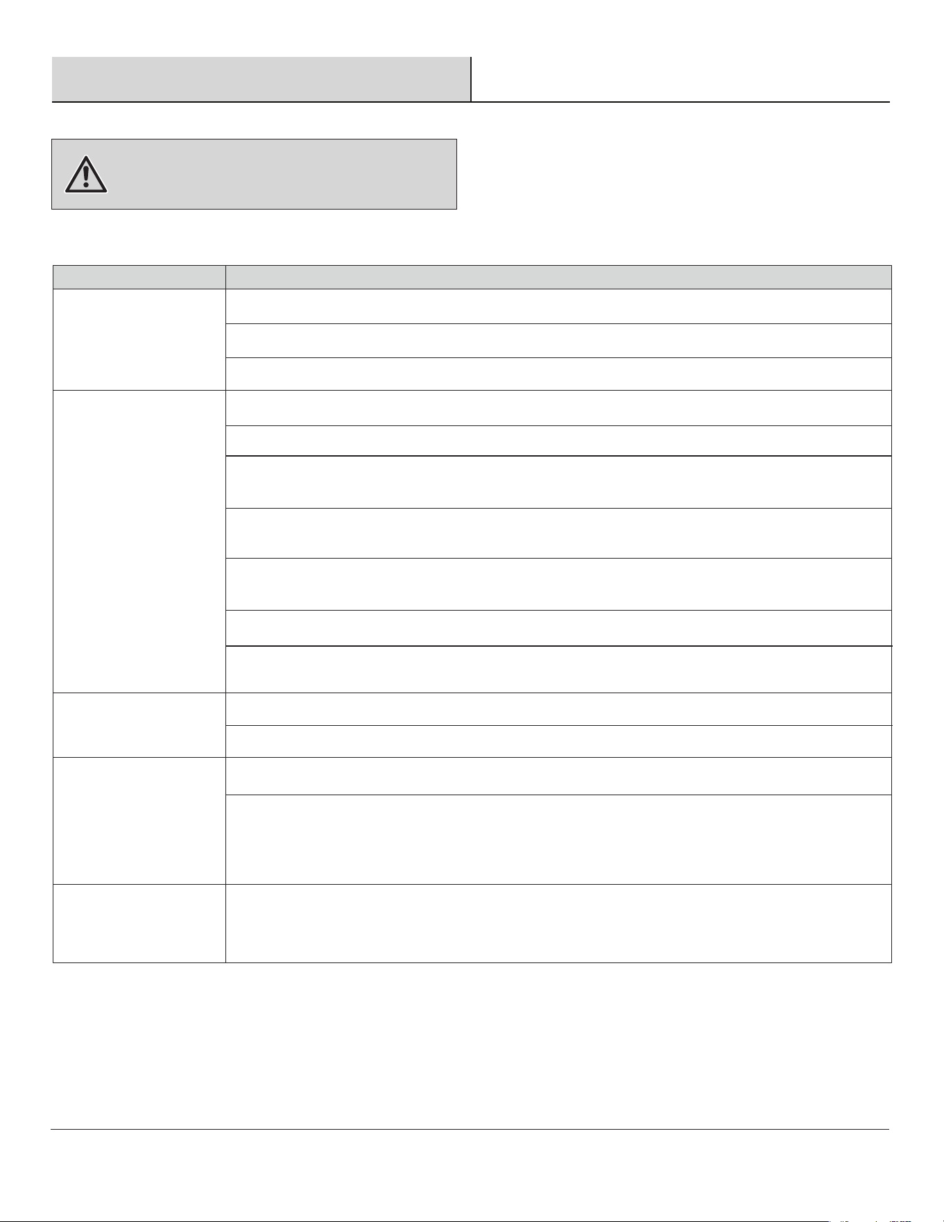
□ Do not connect the fan with wall mounted variable speed control(s) or dimming devices.
□ Check that all blade and blade arm screws are secure.
□ Most fan wobble problems are caused when blade levels are unequal. Check this level by selecting a
point on the ceiling above the tip of one of the blades. Measure from a point on the center of each blade
to the point on the ceiling. Rotate the fan until the next blade is positioned for measurement. Repeat for
each blade. Measurements deviation should be within 1/8 in. Run the fan for 10 minutes.
The fan wobbles.
The remote control is
not working.
□ Check main and branch circuit fuses or breakers.
□ Check line wire connections to the fan and switch wire connections in the switch housing.
□ Reset the transmitter by going through the transmitter “LEARNING PROCESS”.
□ Make sure all motor housing screws are snug.
□ Make sure the screws that attach the fan blade arm to the motor hub are tight.
□ Make sure wire nut connections are not rattling against each other or the interior wall of the switch
housing.
□ Allow a 24-hour "breaking-in" period. Most noises associated with a new fan disappear during this
time.
□ If using the ceiling light kit, make sure the screws securing the glassware are tight. Check that the light
bulb is also secure.
□ Make sure there is a short distance from the ceiling to the canopy. It should not touch the ceiling.
□ Make sure your ceiling box is secure and rubber isolator pads are used between the mounting bracket
and outlet box.
The fan will not start.
The fan sounds noisy.
□ This is normal start-up procedure for DC motor fans. The partial movement during start-up is the result
of the DC motor aligning the internal magnetic poles for proper motor operation. This design saves
electricity and allows the fan to operate much quieter than standard AC motor fans.
Fan moves backwards
and forwards when
turned on.
SolutionProblem
□ Reset the transmitter by going through the transmitter “LEARNING PROCESS”.
This equipment has been tested and found to comply with the limits for a Class B digital device, pursuant to Part 15 of the FCC Rules.
These limits are designed to provide reasonable protection against harmful interference in a residential installation. This equipment
generates, uses, and can radiate radio frequency energy and, if not installed and used in accordance with the instructions, may cause
harmful interference to radio communications. However, there is no guarantee that interference will not occur in a particular installation.
If this equipment does cause harmful interference to radio or television reception, which can be determined by turning the equipment
off and on, the user is encouraged to try to correct the interference by one or more of the following measures:
• Reorient or relocate the receiving antenna.
• Increase the separation between the equipment and receiver.
• Connect the equipment into an outlet on a circuit different from that to which the receiver is connected.
• Consult the dealer or an experienced radio/TV technician for help.
CAUTION:
This device complies with Part 15 of the FCC Rules. Operation is subject to the following two conditions:
(1) This device may not cause harmful interference, and
(2) this device must accept any interference
The following responsible party designated in FCC §2.909 is responsible for this declaration:
Model Number: 102L52MBKDDW/102L52MBKDB/102L52BNDDW/102L52BNLDW
102L60MBKDDW/102L60MBKDB/102L60BNDDW/102L60BNLDW
Company Name: Altitude Air & Fan LLC
Company Address: 3500 Boca Raton Blvd - Suite 717 Boca Raton, FL 33431 United States of America
Telephone Number:
1-844-400-FANS (3267)
rence received, including interference that may cause undesired operation.
Any changes or modifications not expressly approved by the grantee of this device could void the user’s authority to operate the equipment.
17
FCC Statement
Please contact 1-844-400-FANS (3267) for further assistance.
HOMEDEPOT.COM/HOMEDECORATORS


Questions, problems, missing parts? Before returning to the store,
call Home Decorators Collection Customer Service
8 a.m. - 7 p.m., EST, Monday-Friday,
9 a.m. - 6 p.m., EST, Saturday
Retain this manual for future use.
1-844-400-FANS (3267)
HOMEDEPOT.COM/HOMEDECORATORS
GUÍA DE USO Y CUIDADO
GRACIAS
VENTILADOR DE TECHO DE 52 PULGADAS BAYSHIRE
VENTILADOR DE TECHO DE 60 PULGADAS BAYSHIRE
1-844-400-FANS (3267)
Artículo n.° 1005 784 170
Artículo n.° 1005 712 786
Artículo n.° 1005 712 742
Artículo n.° 1005 712 566
Artículo n.° 1005 832 068
Artículo n.° 1005 712 578
Artículo n.° 1005 712 813
Artículo n.° 1005 712 652
Modelo n.° 102L52MBKDDW
Modelo n.° 102L52MBKDB
Modelo n.° 102L52BNDDW
Modelo n.° 102L52BNLDW
Modelo n.° 102L60MBKDDW
Modelo n.° 102L60MBKDB
Modelo n.° 102L60BNDDW
Modelo n.° 102L60BNLDW
HOMEDEPOT.COM/HOMEDECORATORS
Apreciamos la conanza depositada en Home Decorators Collection al comprar este ventilador de techo. Nos esforzamos continua-
mente para crear productos de calidad diseñados para mejorar su hogar. Visítenos en línea para ver nuestra línea completa de
productos disponibles para sus necesidades de mejoramiento del hogar. ¡Gracias por elegir Home Decorators Collection!
¿Tiene preguntas o problemas, o le faltan piezas? Antes de devolver a la tienda,
llame a Atención al Cliente de Home Decorators Collection
Lunes a viernes de 8:00 a.m. a 7:00 p.m., EST, y los sábados de 9:00 a.m. a 6:00 p.m., EST.
2
Instalación .....................................................................
Índice ..............................................................................2
Información de seguridad .............................................2
Garantía ..........................................................................3
Antes de la instalación ..................................................3
6
Ensamblaje .....................................................................7
Índice
13Funcionamiento
Cuidado y limpieza 15
Resolución de problemas 16
Declaración de la FCC 17
............................................................
.......................................................
...........................................
.................................................
Información de seguridad
1.
2.
3.
4
.
5
.
6.
7
.
LEA Y GUARDE ESTAS INSTRUCCIONES
ADVERTENCIA:
ADVERTENCIA:
ADVERTENCIA:
PRECAUCIÓN:
PRECAUCIÓN:
PRECAUCIÓN:
PRECAUCIÓN:
ADVERTENCIA:
ADVERTENCIA:
Para reducir el riesgo de descarga eléctrica, asegúrese de que
se haya cortado la electricidad en la caja de fusibles o el
disyuntor antes de comenzar.
Para reducir el riesgo de incendio o
descarga eléctrica, no use este ventilador con ningún
dispositivo de control de velocidad de estado sólido.
Dañará de forma permanente los circuitos electrónicos.
Todo el cableado debe cumplir con el Código Eléctrico Nacional
“ANSI/NFPA 70” y los códigos eléctricos locales.
Un electricista calificado y autorizado debe realizar la
instalación eléctrica.
La caja eléctrica y la estructura de soporte deben estar montadas
de forma segura y ser capaces de soportar de forma confiable
un mínimo de 15.9 kg (35 lb). Solo debe usar cajas eléctricas
con certificación UL con la etiqueta “Aceptable para soporte de
ventilador de 35 lb (15.9 kg) o menos”.
No coloque objetos en el recorrido de las aspas.
No utilice agua ni detergentes para limpiar el ventilador o las
aspas del ventilador. Un paño seco o ligeramente humedecido
será adecuado para la mayoría de la limpieza.
Después de hacer las conexiones eléctricas, los conductores
unidos deben orientarse hacia arriba y empujarse cuidadosamente
hacia la parte superior en la caja eléctrica. Los cables deben
separarse con el conductor de conexión a tierra y el conductor de
conexión a tierra del equipo en un lado de la caja eléctrica y el
conductor sin conexión a tierra en el otro lado de la caja eléctrica.
Todos los tornillos de fijación se deben revisar y volver a apretar
cuando sea necesario antes de la instalación.
Para reducir el riesgo de lesiones personales,
no doble los soportes de las aspas cuando instale los soportes,
equilibre las aspas o limpie el ventilador. No introduzca
objetos extraños entre las aspas giratorias del ventilador.
Para reducir el riesgo de incendio, descarga
eléctrica o lesión, monte el ventilador en una caja eléctrica que
tenga la etiqueta “aceptable para soporte de ventilador de 35 lb
(15.9 kg) o menos” y use los tornillos incluidos con la caja eléctrica.
Para evitar posibles descargas eléctricas,
corte la electricidad en la caja de fusibles principal antes de
realizar el cableado.
Para reducir el riesgo de lesiones personales,
utilice únicamente los tornillos suministrados con la caja eléctrica.
Para evitar lesiones o daños en el ventilador
u otros artículos, tenga cuidado cuando trabaje cerca del
ventilador o lo limpie.
El ventilador se debe montar con un espacio
mínimo de 2.1 m (7 pies) desde el borde posterior de las
aspas hasta el piso.
Cualquier cambio o modificación no autorizada
expresamente por la parte responsable del cumplimiento
podría anular la autoridad del usuario para usar el equipo.
Para reducir el riesgo de descarga eléctrica,
debe instalarse con un interruptor/control de pared aislante.
Adecuado para su uso en lugares húmedos, cuando planeadoresde
un GFCI protegidos branch circuit.
8.
Úselo únicamente con juegos de luces marcados como "Apto para
usar en ubicaciones".
9.
3
Garantía
Pre-InstallationAntes de la instalación
D
Destornillador
Phillips
Cinta
eléctrica
Alicates
pelacables
Destornillador
plano
Escalera
de mano
NOTA:
52 pulg.
BAJA
MEDIA
ALTA
120
Tamaño del
ventilador
Velocidad
Voltaje Amperaje Vataje
RPM CFM
P.N.
P.B. M.C.
60 pulg.
BAJA
MEDIA
ALTA
120
1.53 pies³
0.08 2.69 70 2527
0.21 15.00 130 5069
0.49 32.62 170 6411
5.39 kgs
(11.89 lbs)
7.82 kgs
(17.24 lbs)
1.84 pies³
0.08 2.32 55 2740
0.15 9.80 100 5440
0.39 24.33 130 6837
6.06 kgs
(13.35 lbs)
8.80 kgs
(19.40 lbs)
Comuníquese con el Equipo de Servicio al Cliente al 1-844-400-FANS (o 3267) o visite www.HOMEDEPOT.com/HOMEDECORATORS
Comuníquese con el 1-844-400-FANS (3267) para obtener más ayuda.
HOMEDEPOT.COM/HOMEDECORATORS
ESPECIFICACIONES
Estas son medidas aproximadas. No incluyen los
amperios y vatios utilizados por el juego de luces.
Garantizamos que el motor del ventilador está libre de defectos de mano de obra y materiales en el momento del envío desde la fábrica
durante un período de por vida después de que el comprador original realiza la compra. También garantizamos que el juego de luces, está
libre de defectos de fabricación y de material en el momento del envío desde la fábrica durante un período de cinco años después de que
el comprador original realiza la compra, excluidos los componentes de vidrio o acrílico y las aspas de madera, que están libres de defectos
de fabricación y de material en el momento del envío desde la fábrica durante un período de dos años después de que el comprador
original realiza la compra. Si se devuelve el producto, aceptamos corregir estos defectos sin costo o, según nuestro criterio, reemplazar el
artículo por un modelo comparable o superior. Para obtener el servicio de garantía, debe presentar una copia del recibo como
comprobante de compra. Usted debe encargarse de todos los costos de desmontar el producto y volver a instalarlo. Esta garantía no cubre
los daños a cualquier pieza, tales como por accidente, mal uso, instalación incorrecta o por la colocación de cualquier accesorio. Debido a
las diferentes condiciones climáticas, esta garantía no cubre ningún cambio en el acabado de latón, incluyendo oxidación, picaduras,
corrosión, deslustre o desconchado. Este tipo de acabado de latón tendrá una vida útil más extensa si se protege de las condiciones
variables del clima. Un cierto "bamboleo" es normal y no se considerará un defecto. Si una persona no autorizada repara este artículo, se
anulará la garantía. No existe otra garantía expresa. Por la presente renunciamos a todas y cada una de las garantías, incluidas, entre
otras, las de comerciabilidad e idoneidad para un propósito en particular en la medida en que lo permita la ley. La duración de cualquier
garantía implícita a la que no se puede renunciar se limita al período que se especifica en la garantía expresa. Algunos estados no
permiten la limitación de la duración de una garantía implícita, por lo que es posible que la limitación anterior no se aplique en su caso. La
tienda minorista no será responsable por daños incidentales, consecuentes o especiales que surjan o estén relacionados con el uso o el
desempeño del producto, excepto que la ley estipule lo contrario. Algunos estados no permiten la exclusión o limitación de los daños
incidentales o consecuentes, de manera que la limitación anterior podría no aplicarse a su caso. Esta garantía le brinda derechos legales
específicos y quizás usted tenga otros derechos que varían según el estado. Esta garantía reemplaza a todas las garantías anteriores. El
cliente debe pagar los costos de envío de cualquier devolución del producto que forme parte de un reclamo de la garantía.
HERRAMIENTAS REQUERIDAS
4
AA
BB
CC
DD
EE
Tornillo del aspa
Descripción
7
FF
GG
HH
Tornillo del juego de luces (preensamblado)
3
Pasador (no a escala) (preensamblado)
Pasador de chaveta (preensamblado)
1
1
2
2
2
1
Tornillo de fijación de la bola colgante (preensamblado)
Tornillo de fijación del conjunto del motor del ventilador (preensamblado)
Tornillo del soporte de montaje (preensamblado)
Pasador de bloqueo (no a escala) (preensamblado)
Tornillos de montaje del soporte del mando a distancia
II
JJ
KK
NOTA:
El herraje se muestra en su
tamaño real.
AA
EE
FF
GG
HH
II
BB
CC
DD
JJ
1
1
Pieza
Conectores de torsión
PACKAGE CONTENTS
Tornillo de la tapa de la batería del mando a distancia
Cantidad
KK
Antes de la instalación (continuación)
3
HERRAJE INCLUIDO
6LL
Bloque de plástico (preensamblado)
LL
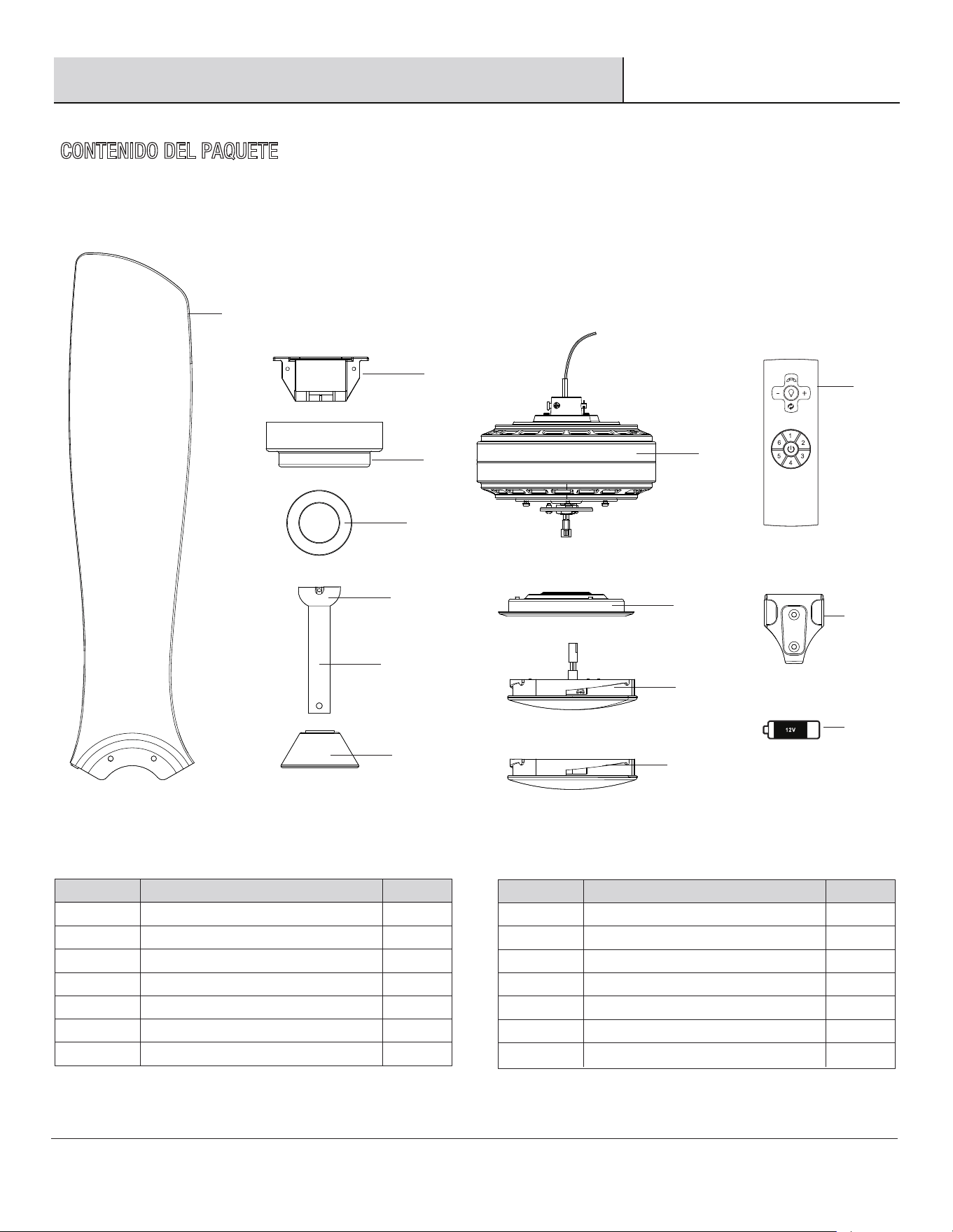
5
Antes de la instalación (continuación)
CONTENIDO DEL PAQUETE
Conjunto del motor del ventilador
Conjunto del juego de luces
J
K
Pieza CantidadDescripción
M
L
Cubierta del juego de luces
1
1
1
1
Soporte del mando a distancia
Mando a distancia
Batería de 12 V
Clavija
Soporte de montaje
3
B
C
D
Pieza
A
CantidadDescripción
F
E
Florón
1
1
1
1
Bola colgante (preensamblado)
Cubierta del florón
G
H
N
O
Tubo descendente (preensamblado)
Embellecedor
Placa del juego de luces
1
1
1
1
1
M
N
O
A
B
C
D
E
F
G
H
J
HOMEDEPOT.COM/HOMEDECORATORS
K
L
Comuníquese con el 1-844-400-FANS (3267) para obtener más ayuda.
6
Instalación
ADVERTENCIA:
1
1
1
3
2
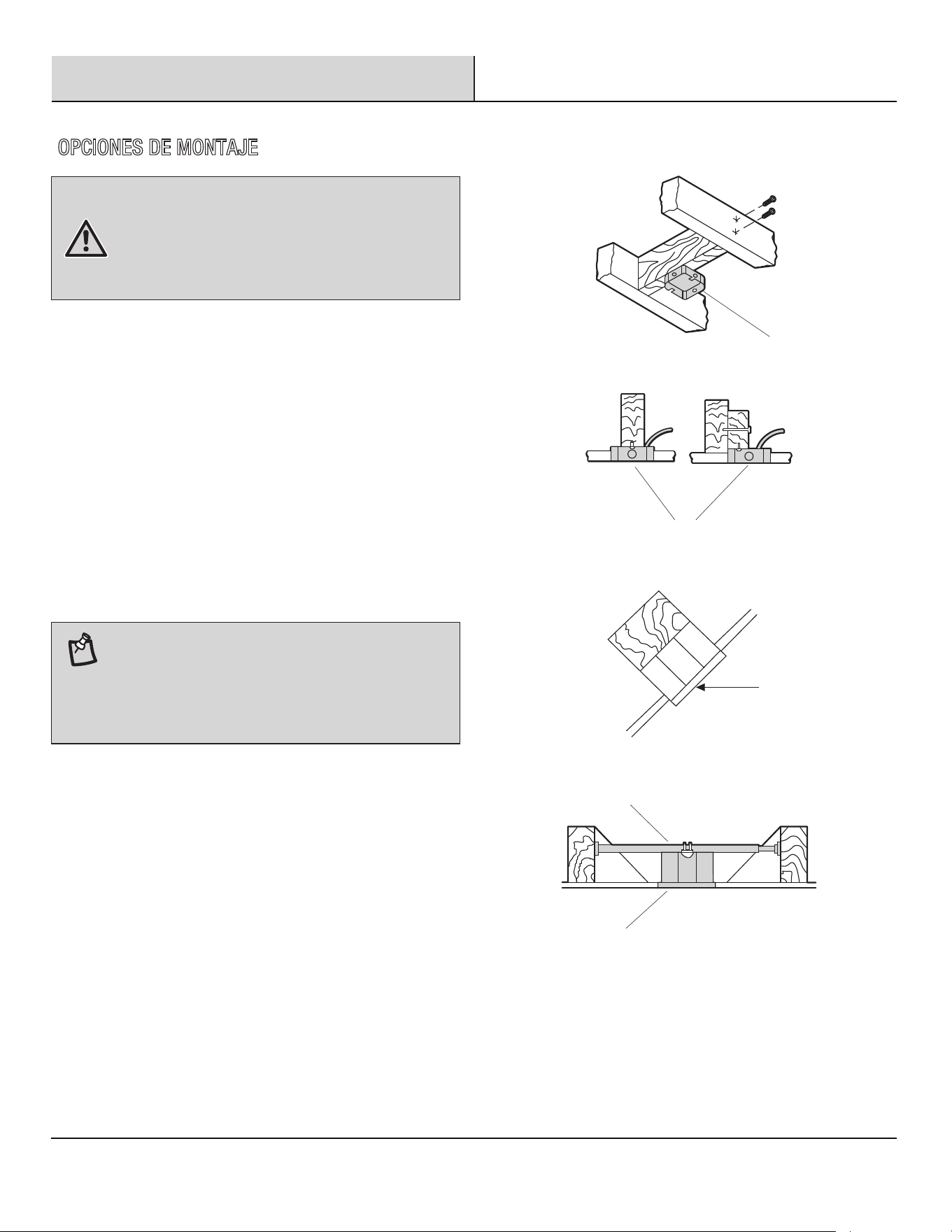
Si su ventilador de techo no tiene una caja de montaje de certificación
UL, debe instalar una. Para ello, siga las instrucciones a continuación:
□ Desconecte la corriente retirando los fusibles o apagando
los disyuntores.
□
□
Fije la caja eléctrica (1) (no incluida) directamente a la estructura
de la edificación. Use sujetadores y materiales adecuados (no
incluidos). La caja eléctrica y sus soportes deben ser capaces de
soportar completamente el peso del ventilador en movimiento (al
menos 35 lb). No utilice una caja eléctrica de plástico.
Las ilustraciones a la derecha muestran tres formas diferentes
de montar la caja eléctrica (no incluida).
□
Para colgar un ventilador en un lugar en el cual hay una lámpara
pero no hay una viga de techo, es posible que necesite una barra
de soporte colgante (3) (no incluida), como se muestra.
NOTA:
Para reducir el riesgo de incendio, descarga
eléctrica o lesión, monte el ventilador en una caja eléctrica que tenga
la etiqueta de aceptable para soporte de ventilador. Es posible que
una caja eléctrica que se suele usar como soporte para las lámparas
no sea aceptable como soporte de ventilador y deba reemplazarse.
En caso de duda, consulte a un electricista calificado.
Es posible que necesite un tubo descendente más
largo para mantener una distancia adecuada a las aspas
cuando se instale en un techo alto inclinado. El ángulo máximo
admisible es 18°. Si el florón toca el tubo descendente, quite la
funda inferior del florón y luego gire 180° el florón antes de
fijarlo a la placa de montaje (2).
OPCIONES DE MONTAJE
DD
GG
E
F
FF
EE
HH
H
HOMEDEPOT.COM/HOMEDECORATORS
Comuníquese con el 1-844-400-FANS (3267) para obtener más ayuda.
7
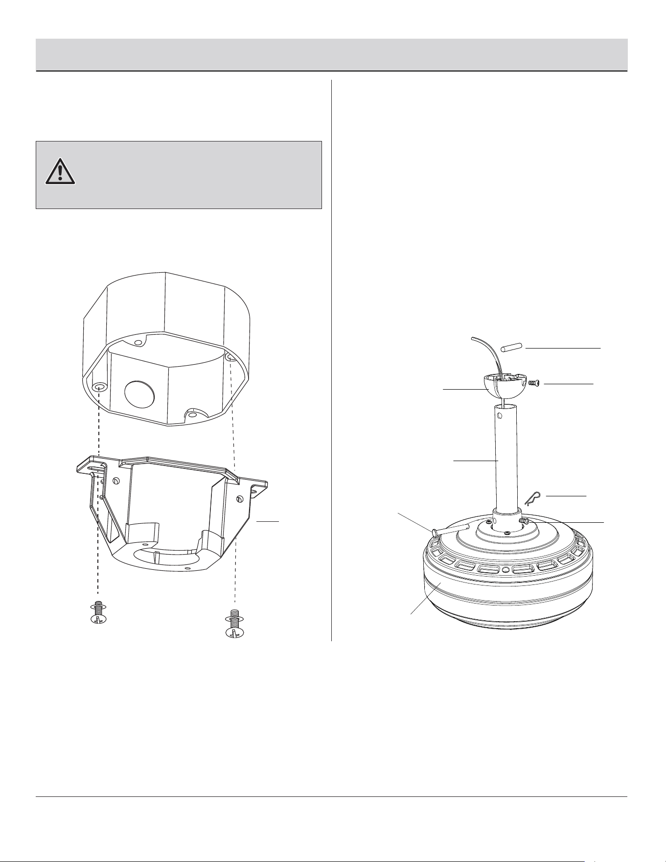
Ensamblaje: Cómo colgar el ventilador
□
Afloje los dos tornillos de fijación del conjunto del motor
del ventilador (HH) del acoplamiento del conjunto del
motor del ventilador (H).
□
□
Conexión del tubo descendente al
conjunto del motor del ventilador
2
1
Fijar el soporte de montaje a la
caja eléctrica
□
Fije el soporte de montaje (B) en la caja eléctrica de
techo con los tornillos y arandelas suministrados con
la caja eléctrica.
ADVERTENCIA:
B
Para reducir el riesgo de incendio, descarga
eléctrica u otras lesiones personales, monte el ventilador solo
en una caja eléctrica o en un sistema de soporte marcado como
aceptable para el soporte del ventilador y utilice los tornillos de
montaje suministrados con la caja eléctrica.
Quite el pasador de chaveta (EE) y el pasador de bloqueo
(FF) del tubo descendente (F). Para quitar la bola colgante
(E) del tubo descendente (F), afloje el tornillo de fijación de
la bola colgante (GG), quite el pasador (DD) y luego deslice
la bola colgante (E) para quitarla del tubo descendente (F).
Extienda con cuidado los cables del ventilador hacia
arriba por el tubo descendente (F). Inserte el tubo
descendente (F) en el acoplamiento del conjunto del
motor del ventilador (H). Alinee los orificios y vuelva a
colocar el pasador de bloqueo (FF) y el pasador de
chaveta (EE). Apriete los tornillos de fijación (HH).
8
3
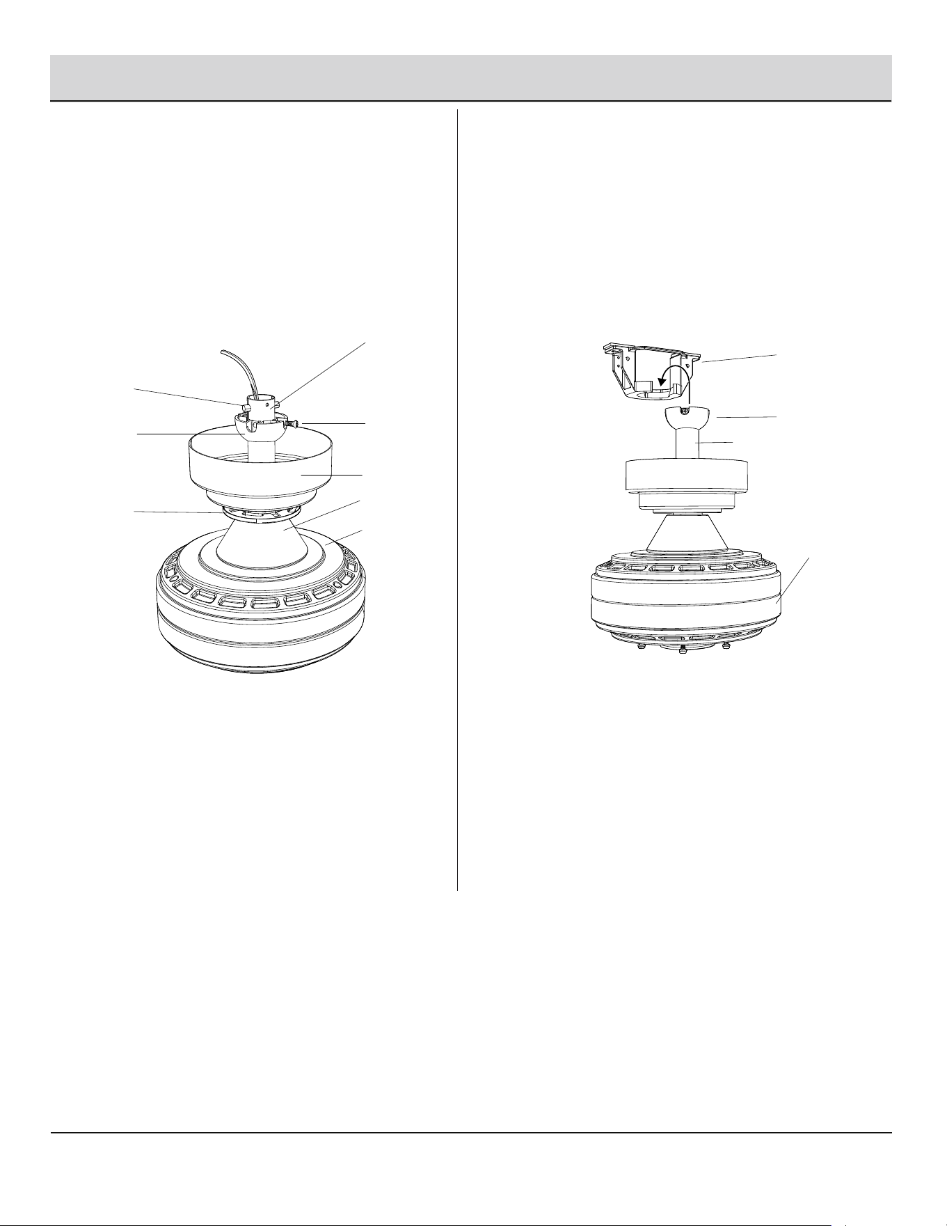
Fijar la tapa del acoplamiento y el
florón al tubo descendente
Ensamblaje: Cómo colgar el ventilador (continuación)
□
4
Colgar el conjunto del motor del
ventilador del soporte de montaje
□
F
DD
GG
E
C
G
H
D
B
E
F
H
Deslice la tapa del acoplamiento (G), la cubierta del florón
(D) y el florón (C) por el tubo descendente (F). Vuelva a
instalar con cuidado la bola colgante (E) en el tubo
descendente (F) y asegúrese de que el pasador (DD) esté
en la posición correcta, que los tornillos de fijación de la
bola colgante (GG) estén apretados y que los cables no
estén enredados.
Levante el conjunto del motor del ventilador (H) hasta su
posición y coloque la bola colgante (E) en el soporte de
montaje (B). Gire el conjunto del motor del ventilador (H)
hasta que la muesca de control caiga en la ranura de
acople y se asiente bien. El tubo descendente (F) no debe
girar si lo hizo bien.
9
Ensamblaje: Cómo colgar el ventilador (continuación)
5
Conexiones eléctricas
ADVERTENCIA:
ADVERTENCIA:
Siga los siguientes pasos para conectar el ventilador a los cables
de alimentación de su casa. Para fijar los conectores de torsión
(CC) incluidos con el ventilador, envuelva cinta aislante alrededor
de los conectores
□ Conecte el cable negro (vivo) del techo al cable negro del
conjunto del motor del ventilador (H).
□ Conecte el cable blanco (neutro) del techo al cable blanco del
conjunto del motor del ventilador (H).
□ Si la caja eléctrica (1) tiene un cable de conexión a tierra (verde
o cobre desnudo), conéctelo a los cables de conexión a tierra
del ventilador; de lo contrario, conecte el cable de conexión a
tierra de la bola colgante (E) al soporte de montaje (B).
□ Fije cada conexión de cables con un conector de torsión de
plástico (CC) incluido con el herraje eléctrico.
□ Después de conectar los cables, sepárelos para que los cables
verde y blanco estén en un lado de la caja eléctrica (1) y los
cables negro y azul en el otro lado. Meta cuidadosamente las
conexiones de los cables en la caja eléctrica (1).
CC (x3)
1
H
Negro Blanco Verde
Negro Blanco Verde
E
Comuníquese con el 1-844-400-FANS (3267) para obtener más ayuda.
HOMEDEPOT.COM/HOMEDECORATORS
Compruebe que todas las conexiones estén bien
apretadas, incluida la conexión a tierra, y que no se vea ningún cable
sin aislamiento en los conectores de torsión, excepto el cable a tierra.
Para evitar posibles descargas eléctricas,
asegúrese de que la electricidad esté apagada en el disyuntor
eléctrico o la caja de fusibles principal antes de realizar el cableado.
J
J
F
10
6
Fijar el conjunto del motor del ventilador al soporte de montaje
□
Quite los dos tornillos del soporte de montaje (II) del soporte de montaje (B).
□
Fije el florón (C) al soporte de montaje (B) con los dos tornillos del soporte de montaje (II) que quitó antes.
□
Apriete los tornillos de soporte de montaje (II).
Ensamblaje: Cómo colgar el ventilador (continuación)
□ Alinee la forma oval del florón (C) con la cubierta del florón (D). Empuje la cubierta del florón (D) hacia arriba hasta que la
cabeza del tornillo (II) haga contacto con las ranuras en la cubierta del florón (D) y luego gírela hasta que quede bien fijada
a la parte inferior del florón (C).
II
C
D
B
□
Sujete las aspas del ventilador (A) al conjunto del motor del ventilador (H) una a una.
Fije los tornillos del soporte del aspa (AA) uno a uno.
Comuníquese con el 1-844-400-FANS (3267) para obtener más ayuda.
HOMEDEPOT.COM/HOMEDECORATORS
□
Sujetar las aspas al conjunto del
motor del ventilador
7
Ensamblaje: Colocar las aspas del ventilador
Quite los seis tornillos de las aspas (AA) y seis bloques de plástico (LL)
del conjunto del motor del ventilador (H).
11
H
A
AA
LL
12
Ensamblaje: Instalar el juego de luces
□
Sujetar la placa del juego de luces y el conjunto del juego de
luces al conjunto del motor del ventilador
8
BB
J
□
H
J
L
K
□
□
Quite los tres tornillos preensamblados del juego de luces (BB)
en el conjunto del motor del ventilador (H).
Fije la placa del juego de luces (J) al conjunto del motor del
ventilador (H). Apriete bien los tornillos del juego de luces (BB).
Conecte el cable de alimentación de la luz, alinee las dos marcas
de flechas en la placa del juego de luces (J) y el conjunto del
juego de luces (K), y fije el conjunto del juego de luces (K) a la
placa del juego de luces (J) girando con fuerza hacia la izquierda.
Opcional: fije la cubierta del juego de luces (L) a la placa del juego
de luces (J) girando con fuerza hacia la izquierda si no prefiere el
conjunto del juego de luces (K).
13
Funcionamiento
ADVERTENCIA:
ADVERTENCIA:
NOTA:
Si desea usar otro mando a distancia (M) con su ventilador nuevo o instalar
más de un ventilador en el área, instálelo uno por uno siguiendo los pasos
a continuación:
Apague la fuente de alimentación para iniciar el proceso de aprendizaje.
□
Vuelva a alimentar la unidad.
□
□
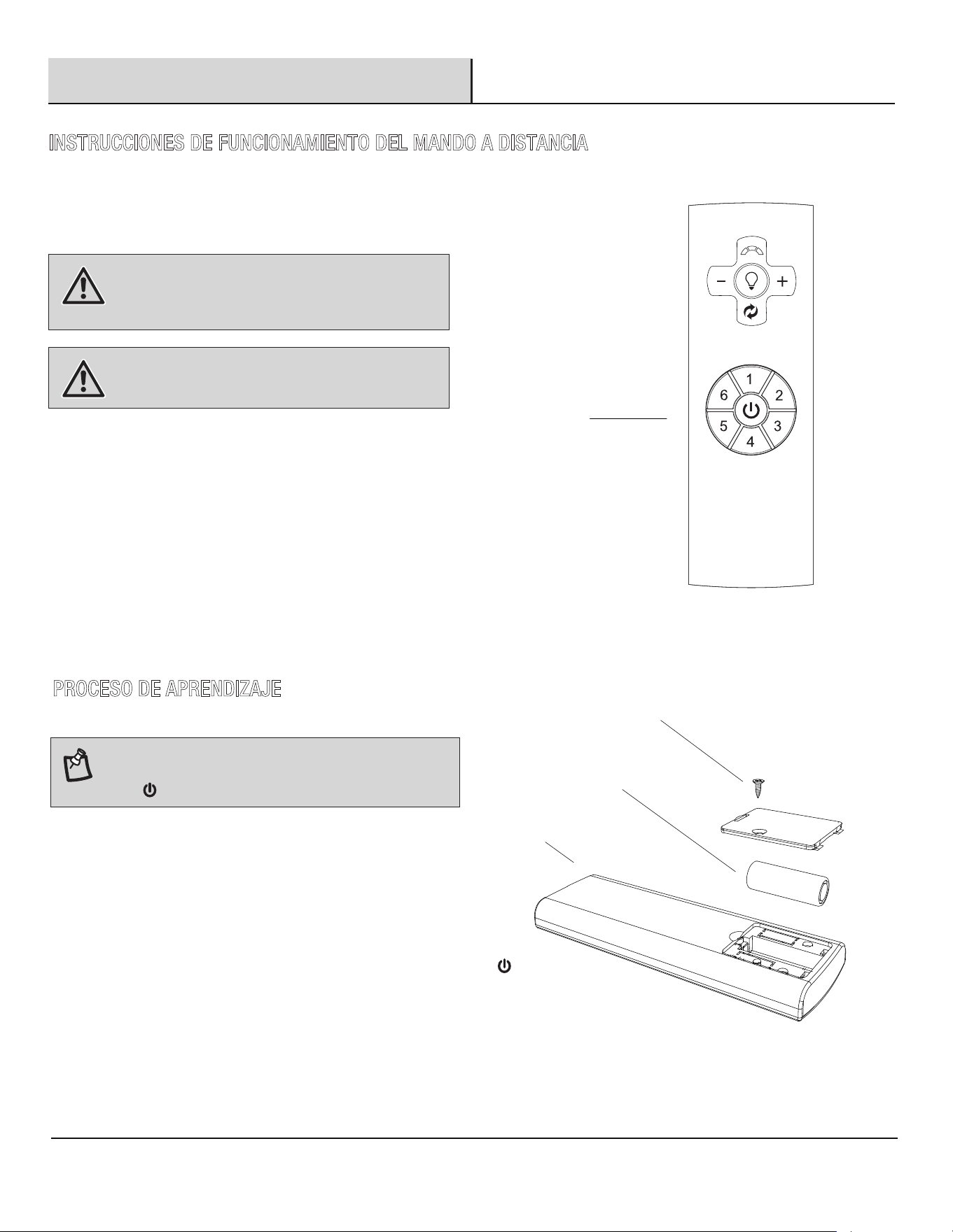
Instale una batería de 12 V (O) en el mando a distancia (M). Coloque el
tornillo de la cubierta de la batería (KK) después de la instalación. Para
evitar daños al mando a distancia, retire la batería si no la va a utilizar
durante un largo período de tiempo.
M
KK
O
M
HOMEDEPOT.COM/HOMEDECORATORS
INSTRUCCIONES DE FUNCIONAMIENTO DEL MANDO A DISTANCIA
No haga cortocircuito, desmonte, caliente,
conecte de manera inadecuada ni arroje las baterías usadas al
fuego. No recargue ni mezcle las baterías con baterías usadas
o de otros tipos. Quite de inmediato las baterías usadas.
a) Las baterías deben eliminarse de manera
apropiada, lo que incluye mantenerlas fuera del alcance de los
niños; y b) Incluso las baterías usadas pueden causar lesiones.
PROCESO DE APRENDIZAJE
Comuníquese con el 1-844-400-FANS (3267) para obtener más ayuda.
Dentro de los siguientes 30 segundos, mantenga presionado el botón
por 5 segundos para ingresar a la función de aprendizaje. Una vez que
el receptor haya detectado la frecuencia establecida, se emitirá un sonido
cuando se haya completado el emparejamiento.
Una vez que encienda la alimentación de CA, no presione
ningún otro botón en el mando a distancia antes de presionar el
botón (FAN ON/OFF). Esto hará que falle el procedimiento.
14
Funcionamiento (continuación)
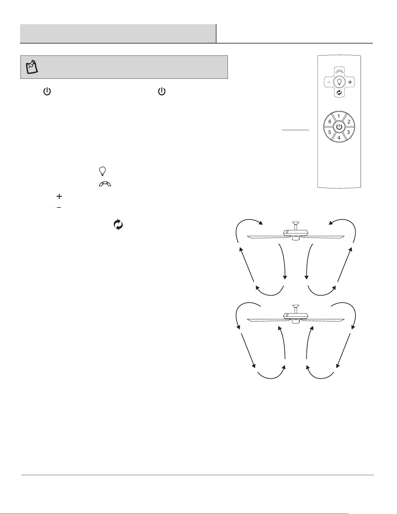
2. Funciones de velocidad
Número 1/ 2/ 3/ 4/ 5/ 6, botón de velocidad
Presionar y soltar el botón una vez cambiará la velocidad del ventilador.
□
Apagar el ventilador. La función de memoria del ventilador almacenará el ajuste actual para la
próxima vez que se lo use.
□
(En sentido antihorario) Un flujo de aire hacia abajo crea un efecto de
enfriamiento. Esto le permite ajustar su aire acondicionado a un valor más
alto sin afectar su comodidad.
(En sentido horario) Un flujo de aire ascendente aleja el aire caliente del
techo. Esto le permite ajustar su calefacción a un valor más bajo sin afectar
su comodidad.
4. Botón de inversión del ventilador (se debe presionar cuando el ventilador
esté funcionando)
□
□
3. Funciones de las luces
□ Presionar y soltar el botón una vez encenderá o apagará las luces.
□
Presione para aumentar al nivel de iluminación deseado.
□
Presione para reducir al nivel de iluminación deseado.
M
NOTA:
□ Presione y suelte el botón para seleccionar la temperatura de color deseada.
Al iniciar, el ventilador de techo oscilará de atrás para adelante. Esto
es un FUNCIONAMIENTO NORMAL del ventilador de CC al ingresar al ciclo de
calibración. El ventilador NO ESTÁ AVERIADO.
1. Botón del ventilador. - Presione y suelte el botón para encender o apagar el ventilador.
15
Funcionamiento (continuación)
Cuidado y limpieza
□ Verifique las conexiones de soporte, los soportes y los
accesorios de las aspas dos veces al año. Asegúrese de
que estén fijos. Debido al movimiento natural del
ventilador, algunas conexiones pueden aflojarse con el
tiempo. No es necesario quitar el ventilador del techo.
□ Limpie su ventilador periódicamente. Únicamente debe
usar un cepillo suave o un paño sin pelusa para evitar
dañar el acabado. El enchapado se sella con una laca
para minimizar la decoloración o el deslustre.
□ (Opcional) Aplique una capa ligera de pulimento para
muebles a las aspas de madera.
□ (Opcional) Cubra las pequeñas rayaduras con una ligera
aplicación de betún para zapatos.
Qué hacer
□ No use agua al limpiarlo. El agua podría dañar el motor o la
madera, o posiblemente causar una descarga eléctrica.
□ No aplique aceite a su ventilador o motor. El motor cuenta
con rodamientos de bola sellados que están lubricados
permanentemente.
Qué no hacer
□
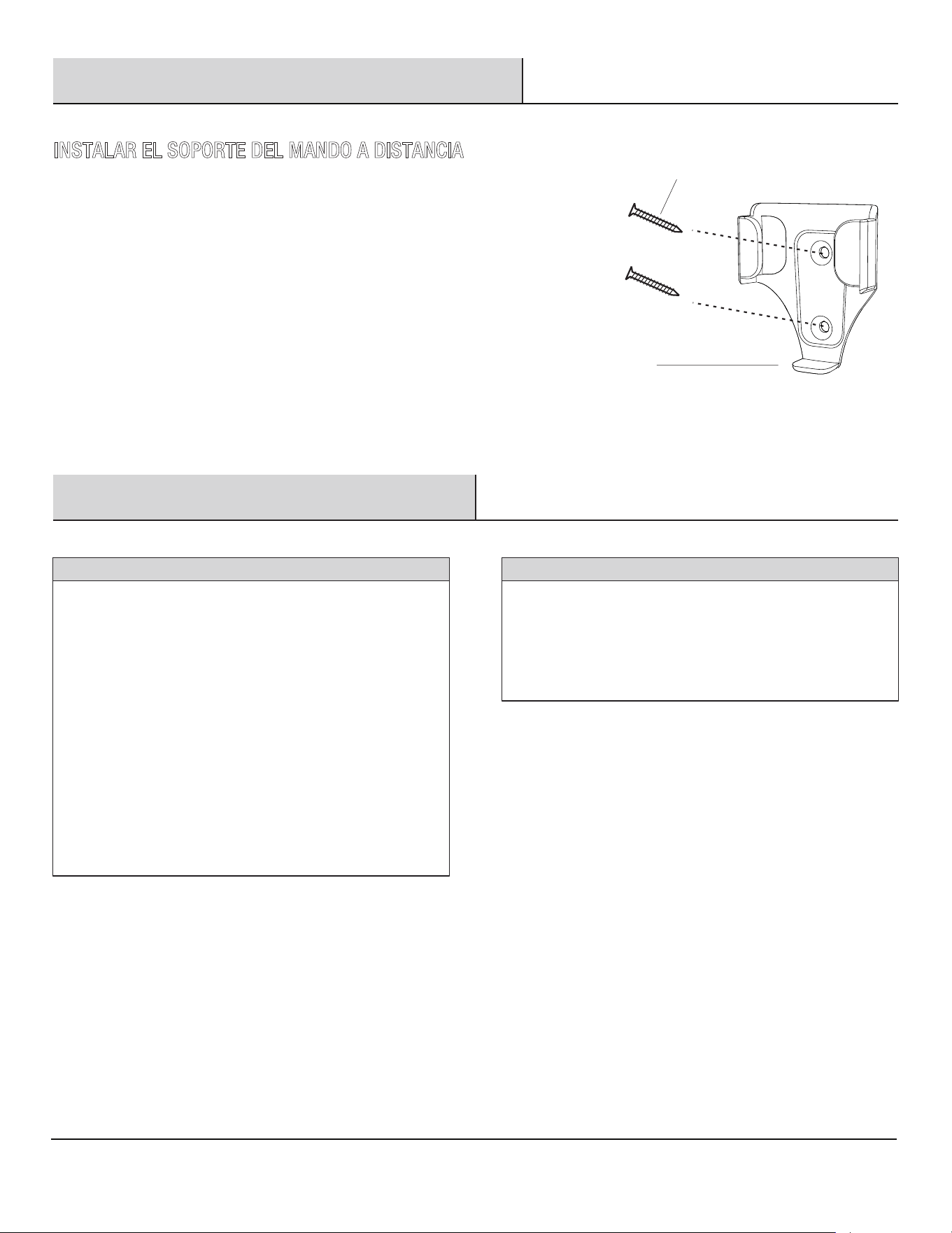
Fije el soporte del mando a distancia (N) con los dos tornillos de montaje
del soporte del mando a distancia (JJ).
INSTALAR EL SOPORTE DEL MANDO A DISTANCIA
JJ
N
Comuníquese con el 1-844-400-FANS (3267) para obtener más ayuda.
HOMEDEPOT.COM/HOMEDECORATORS
16
Resolución de problemas
ADVERTENCIA:
17
Asegúrese de que la corriente esté apagada
en la caja del panel eléctrico antes de intentar cualquier
reparación. Consulte la sección, “Realizar las conexiones
eléctricas” en la página 9.
□
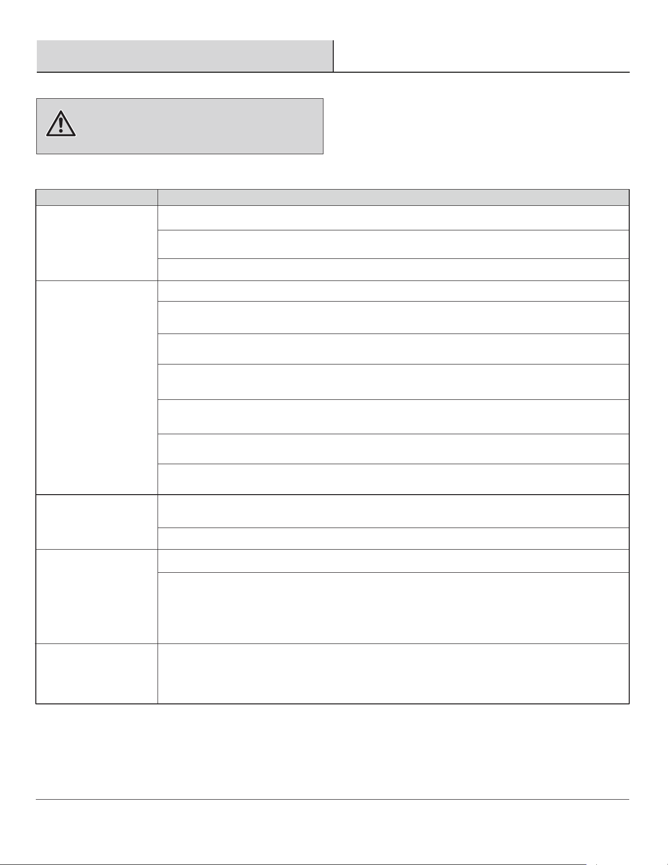
SolutionProblem
□ No conecte el ventilador con controles de velocidad variable montados en la pared o dispositivos de a
tenuación.
□
Verifique que todos los tornillos de las aspas y los brazos de las aspas estén apretados firmemente.
□
La mayoría de los problemas de oscilación del ventilador se producen cuando las aspas no tienen el mismo
nivel. Para verificar el nivel, seleccione un punto del techo que esté sobre la punta de una de las aspas. Mida
desde un punto del centro de cada aspa hasta el punto del techo. Rote el ventilador hasta que el aspa
siguiente esté colocada para la medición. Repita este proceso en todas las aspas. La desviación de la medición
debe estar dentro de un rango de 0.31 cm (1/8 de pulgada). Deje el ventilador encendido durante 10 minutos.
El ventilador oscila.
El mando a distancia
no funciona.
□ Verifique los fusibles o disyuntores del circuito principal y del de derivación.
□
Verifique las conexiones de los cables de la línea de alimentación con el ventilador y las conexiones de
los cables del interruptor en la carcasa del interruptor.
□
Reinicie el transmisor pasando por el “PROCESO DE APRENDIZAJE” del transmisor.
□ Asegúrese de que todos los tornillos de la carcasa del motor estén bien ajustados.
□
Asegúrese de que los tornillos que fijan los brazos de las aspas del ventilador al cubo del motor estén
apretados.
□ Asegúrese de que las conexiones de los conectores de torsión no estén chocando entre sí o con la pared
interior de la carcasa del interruptor.
□ Deje que pase un período de 24 horas de "asentamiento". La mayoría de los ruidos asociados con un
ventilador nuevo desaparecen luego de este período.
□ Si usa un juego de luces de techo, asegúrese de que los tornillos que sujetan el vidrio estén apretados
firmemente. Asegúrese de que todas las bombillas estén ajustadas correctamente.
□
Asegúrese de que haya una pequeña distancia entre el techo y la cubierta. La cubierta no debe tocar
el techo.
□ Asegúrese de que la caja del techo esté bien sujeta y de que se utilicen almohadillas aislantes de goma
entre el soporte de montaje y la caja eléctrica.
El ventilador no enciende.
El ventilador hace ruido.
Este es el procedimiento normal de arranque de los ventiladores de motor de CC. El movimiento parcial
durante el arranque es el resultado de la alineación de los polos magnéticos internos del motor de CC
para su funcionamiento correcto. Este diseño ahorra electricidad y permite que el ventilador sea más
silencioso que un ventilador normal de CA.
El ventilador se mueve
hacia adelante y atrás
cuando se enciende.
SoluciónProblema
□
Reinicie el transmisor pasando por el “PROCESO DE APRENDIZAJE” del transmisor.
Este equipo ha sido probado y encontrado en cumplimiento con los límites correspondientes a un dispositivo digital de la Clase B,
conforme a la Parte 15 de las Reglas de la FCC. Estos límites están diseñados para brindar una protección razonable contra la interferencia
dañina en una instalación residencial. Este equipo genera, utiliza y puede emitir energía de radiofrecuencia y, si no se instala y utiliza de
acuerdo con las instrucciones, puede causar interferencias perjudiciales en las radiocomunicaciones. Sin embargo, no existe garantía de
que no ocurra interferencia en una instalación en particular. Si este equipo efectivamente causa interferencia dañina a la recepción de
radio o televisión, lo cual puede determinarse apagando y encendiendo el equipo, se recomienda al usuario que trate de corregir la
interferencia realizando uno o varios de los siguientes pasos:
• Cambiar de dirección o de lugar la antena receptora.
• Aumentar la separación entre el equipo y el receptor.
• Conectar el equipo en un tomacorriente en un circuito diferente de donde esté conectado el receptor.
• Consultar al concesionario o a un técnico de radio/TV con experiencia para que le ayude.
PRECAUCIÓN:
Este equipo cumple con la parte 15 de las reglas de la FCC. El funcionamiento está sujeto a las siguientes dos condiciones:
(1) Este dispositivo no puede causar interferencia dañina, y
(2) Este dispositivo debe aceptar toda interferencia recibida, incluso la que puede causar un funcionamiento indeseado.
La siguiente parte responsable designada en FCC §2.909 es responsable de esta declaración:
Número de modelo: 102L52MBKDDW/102L52MBKDB/102L52BNDDW/102L52BNLDW
102L60MBKDDW/102L60MBKDB/102L60BNDDW/102L60BNLDW
Nombre de la compañía: Altitude Air & Fan LLC
Dirección de la compañía: 3500 Boca Raton Blvd - Suite 717 Boca Raton, FL 33431 United States of America
Número de teléfono:
1-844-400-FANS (3267)
Todo cambio o modificación que no esté aprobado expresamente por el concesionario
de este dispositivo podría invalidar la autoridad
del usuario para usar el equipo.
17
Declaración de la FCC
Comuníquese con el 1-844-400-FANS (3267) para obtener más ayuda.
HOMEDEPOT.COM/HOMEDECORATORS


¿Tiene preguntas o problemas, o le faltan piezas? Antes de devolver a la tienda,
llame a Atención al Cliente de Home Decorators Collection
Lunes a viernes de 8:00 a.m. a 7:00 p.m., EST,
y los sábados de 9:00 a.m. a 6:00 p.m., EST
Guarde este manual para su uso futuro.
1-844-400-FANS (3267)
HOMEDEPOT.COM/HOMEDECORATORS