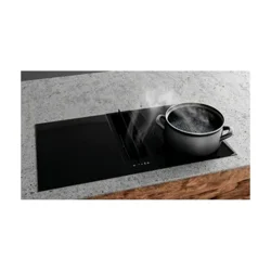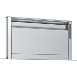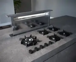

SU-DD2-L
STONE
EN INSTALLATION, USE AND MAINTENANCE INSTRUCTION

2
SU-DD2-L

EN
Keep these instructions for use with the ap-
pliance. If the appliance should be sold or
passed on to others, make sure that the in-
structions are passed on with it. We thank
you for taking note of these suggestions be-
fore installing and using the appliance. They
have been written for your personal safety
and the safety of others.
TO THE ATTENTION
OF THE USER
WARNING
● It is not allowed to cook food over open ames
(ambé) or operate gas hobs without pots or pans
on them under the hood itself (the ames sucked
into the hood might damage the appliance).
● Frying under the appliance must be done un-
der constant supervision as hot oils and fats may
ignite. Respect the guidelines for cleaning and
replacement of grease lters. Accumulated depo-
sits of grease are a re hazard.
● This appliance must not be used over cook tops
powered by wood or coal or in any case, over
cook tops with power levels that could damage
the appliance. Never use steam or high-pressure
devices for cleaning your hood (regulations re-
garding electrical safety).
● Never use the cooker hood without the grease
lters.
● The minimum distance between the Downdraft
(closed) and the surface above it must be at least
400 mm.
● When handling the downdraft, never put your
hands in the eld of action of the extractable unit.
Constantly seeking to improve our products, we
reserve the right to modify their technical, fun-
ctional, or aesthetic characteristics deriving from
their upgrading. In the case of the version with
external motor, fornormal downdraft operation,
it is necessary to use a suctioning unit (external
motor) made by the same manufacturer. The air
collected must not be conveyed into a ue used
for smoke or fumes from appliances powered by
anything other than electricity (central heating sy-
stems, etc.). As far as discharging exhaust air is
concerned, please follow the guide- lines given
by competent authorities.
SAFTEY INSTRUCTIONS
These hoods have been designed for personal
use in the home. The appliance must be used by
adults. Make sure that the appliance is out of re-
ach of children and that they do not use it to play
with. Make sure that children do not operate the
controls.
● When the appliance is delivered, check the
overall appearance of the packaging. Any remar-
ks should be written on the delivery coupon, of
which you keep a copy. Your appliance is desi-
gned for normal domestic use. It is not designed
for commercial or industrial use, or for purposes
other than those for which it was designed.
● Any consequences of or damage from incorrect
installation or incorrect use of the appliance will
not be covered by the manufacturer’s guarantee.
● Do not ever change or try to change the charac-
teristics of this appliance. This would be a danger.
Repairs must be performed only by an authorised
technician. Always disconnect the hood before
carrying out cleaning or maintenance operations.
● Adequately ventilate the room when a cooker
hoodand other appliances, powered by energy
other than electricity, are used simultaneously,
so that the hood does not suck anycombustion
fumes.
It is designed to work in both suctioning mode,
with outside evacuation, and ltering mode.
3
SU-DD2-L

EN
INSTALLING THE COOKER HOOD .....................................................................................5
HOW TO USE THE COOKER HOOD .................................................................................18
Grease lter removal, mounting the activated charcoal lter ..........................................20
Electrical connection of the cooker hood ........................................................................21
HOW THE COOKER HOOD WORKS .................................................................................22
CLEANING THE COOKER HOOD .....................................................................................26
OPERATIONAL ANOMALIES .............................................................................................27
AFTER SALES SERVICE ...................................................................................................27
CONTENTS
4
SU-DD2-L
EN
INSTALLING THE
COOKER HOOD
1. Before carrying out the appliance installation, please check that all components are not damaged, in
such a case contact your retailer and do not carry out any installation operation. Before the installation
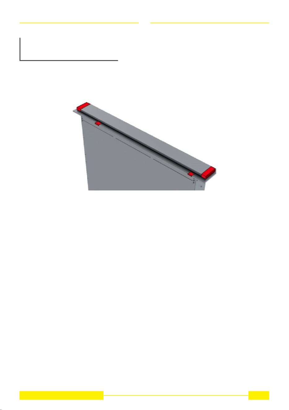
of the Downdraft, please remove the safety piece you can see in the picture (Fig. 1).
Furthermore, please read carefully all of the following installation instructions.
• Use an air exhausting pipe whose maximum length does not exceed 5 meters.
• Limit the number of elbows in the piping,since each elbow reduces the air capacity of 1 linear meter.
(Ex. : if you use no. 2 x 90 ° elbows, the length of piping should not exceed 3 meters).
• Avoid abrupt direction changes.
• Use a 150 mm. constant diameter pipe for the whole length.
• Use piping approved by standards in force.
The manufacturer shall not be deemed responsible for air capacity or noise problems caused by failure
to comply with the above instructions and no warranty on the product shall be provided.
2. Before making the hole, check that there are no structural or other parts inside the cabinet, where
the appliance is to be placed, which could hinder a proper installation. Check that the dimensions of the
Downdraft and the ones of the cook top are compatible with the cabinet so that the installation can be
carried out properly.
5
SU-DD2-L
EN
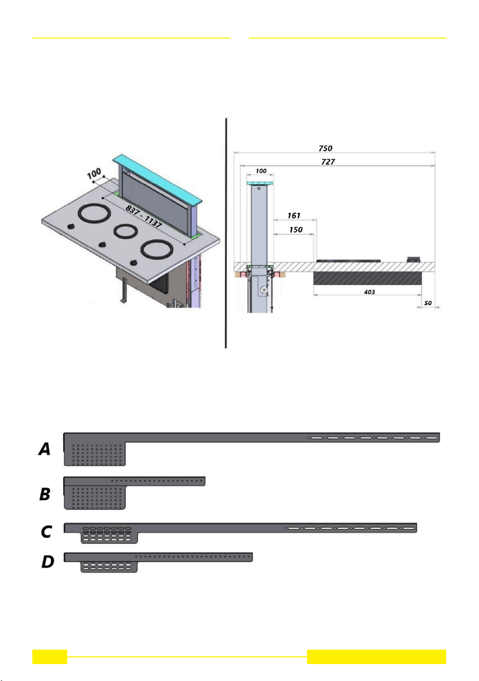
3. Make a rectangular hole 837x100 mm for the 880mm version or 1137x100 mm for the 1180mm ver-
sion in the rear part of the hob (see g. 2).
4. Take the accessories supplied in the package (A-B-C-D see g.3),
Fig. 3
6
SU-DD2-L
Fig. 2
EN
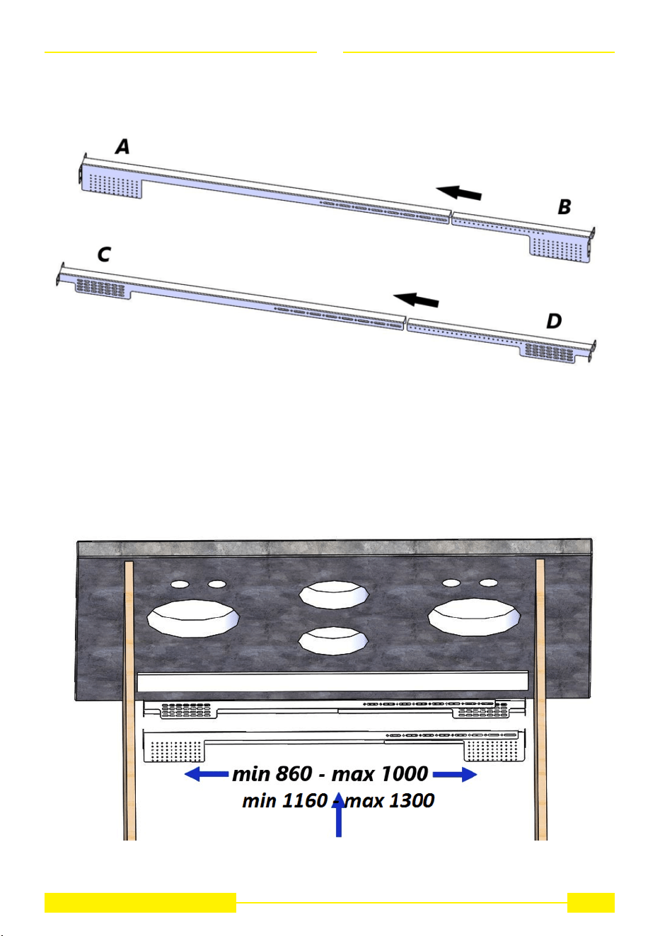
assemble part A with B and C with D (g. 4).
7
SU-DD2-L
Fig. 4
5. Install the preassembled accessories in correspondence with the hole drilled (g. 5), bearing in mind
that they can cover different types of furniture from a minimum dimension of 860mm to a maximum
dimension of 1000mm.
Fig. 5
EN
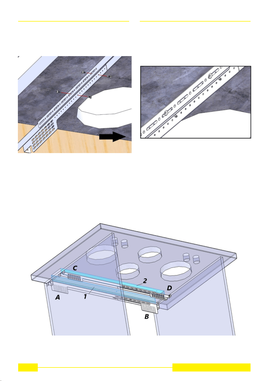
Fix the width of the pairs of accessories using the screws supplied in the special slots, n. 2 screws on
each side (g. 6) taking care not to screw them completely.
Fig. 6
Position the accessories against the base of the hob
(A + B side 1 / C + D side 2 of the rectangular hole see g. 7)
Fig. 7
8
SU-DD2-L
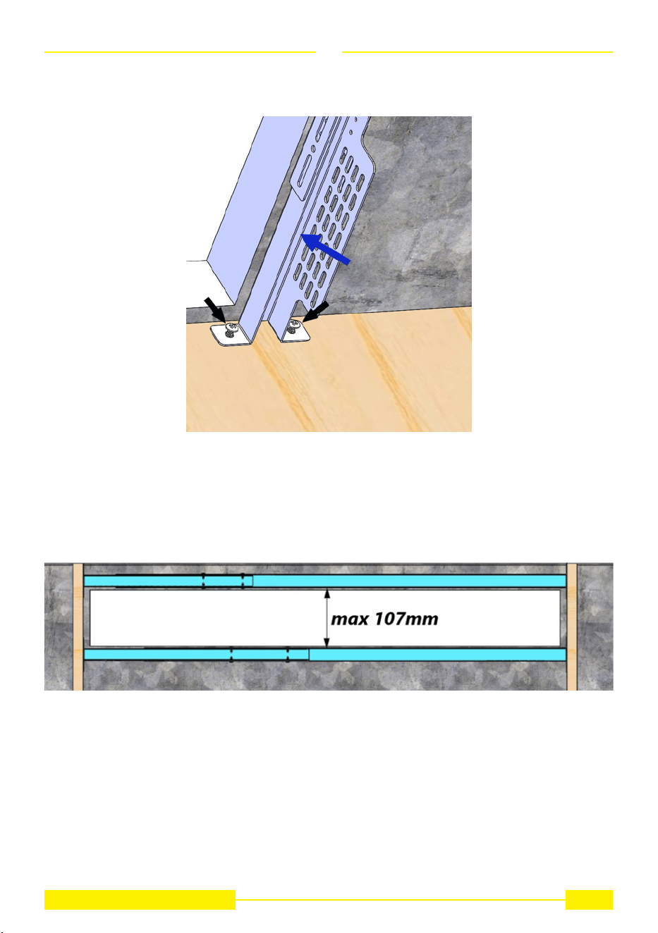
EN
and x them on both sides with screws (g. 8).
9
SU-DD2-L
Fig. 8
Warning: the accessories must be xed in correspondence with the rectangular hole (each pair on each
long side) at a maximum distance of 107mm (g. 9)
Fig. 9
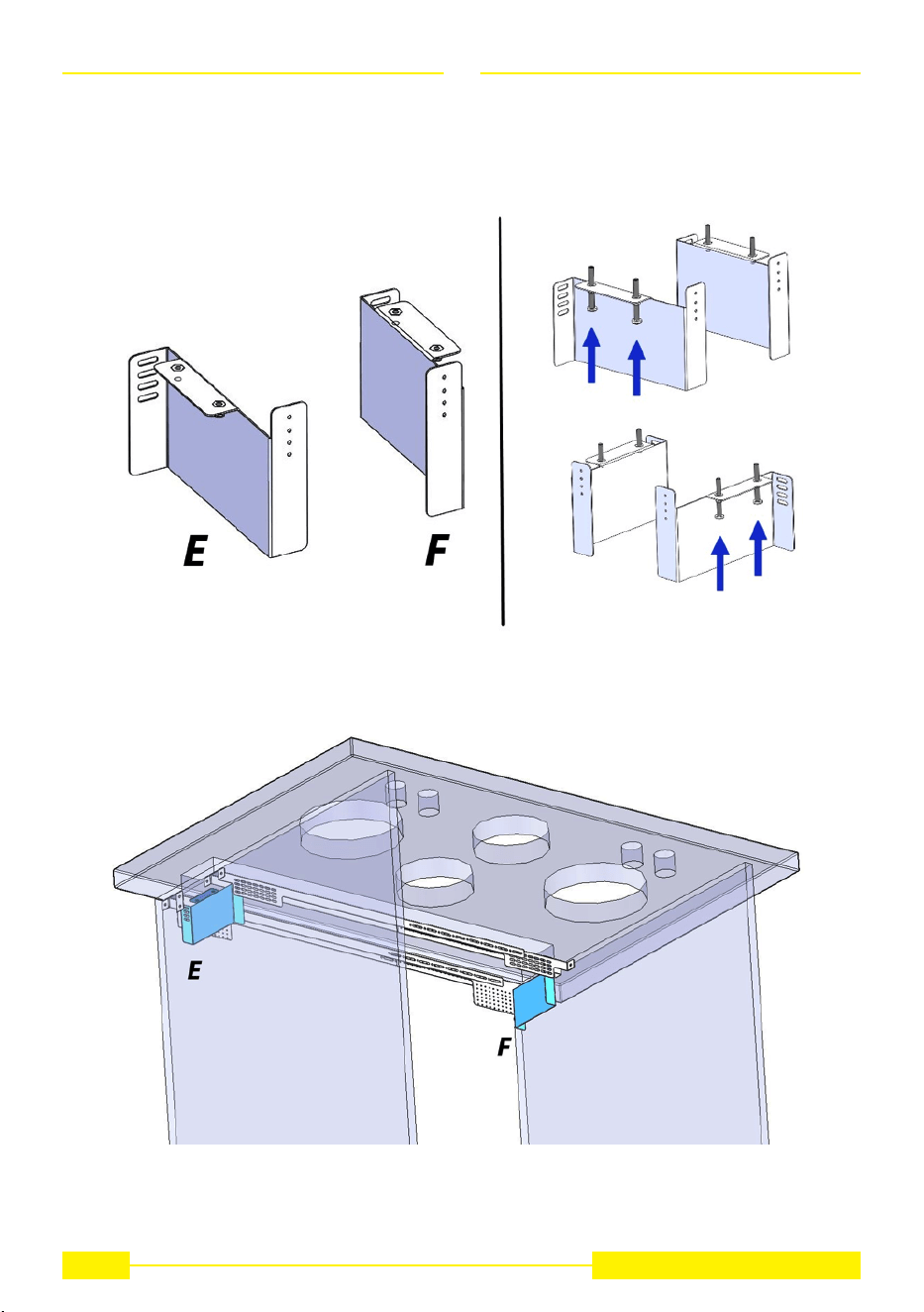
EN
(for an good assembly take the components “E - F” g.10 and insert them between the accessories,
respectively E for the left part and F for the right part, see g.11, in order to check the correct positioning
at the height above said).
Fig. 10
Fig. 11
10
SU-DD2-L
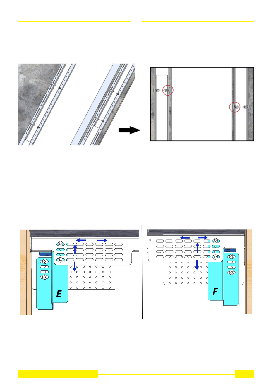
EN
Further expedient x the accessories so that the screws previously inserted to lock the width do not go
beyond the rectangular hole (see g. 12), this to prevent the downdraft from hitting the screws during
installation.
11
SU-DD2-L
Fig. 12
Fig. 13
Before proceeding to the next point, remember to tighten the screws left slow and check that everything
is stable.
6. Take the E - F components (if not present, insert the adjustment screws as shown in g.10) position
them as previously seen (E for the left part and F for the right part, see g.11) and x them on both the
sides with screws (g. 13).
Note well the xing system has several slots to allow adjustments of the downdraft both on the basis
of its width (left - right) and on the thickness of the top to be glued on the downdraft (top - bottom) (see
g. 13).
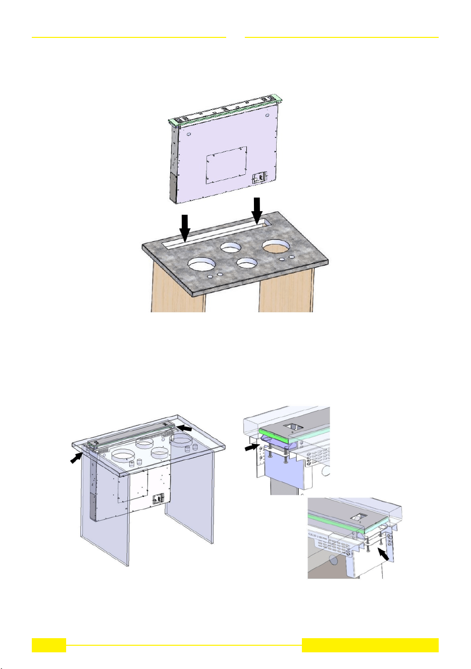
EN
7. Install the downdraft in the hole made, inserting it from above (g. 14),
Fig. 14
Fig. 15
Place the downdraft brackets on the adjustment screws previously preassembled in the E - F compo-
nents (g. 15).
12
SU-DD2-L
EN
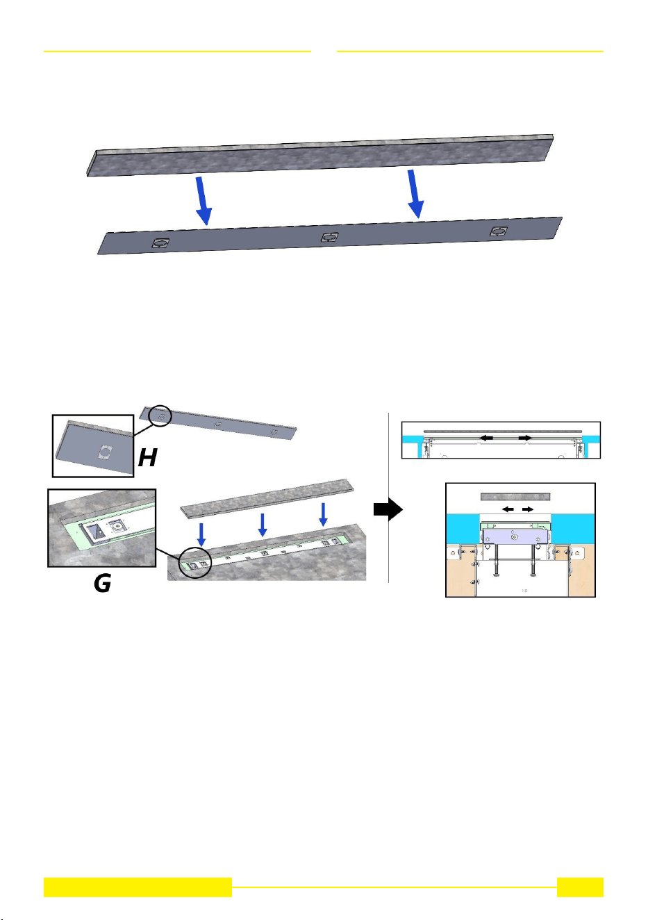
To determine the correct line-up of the downdraft, place the part (glued in the previous step) inside the
rectangular niche, making the magnets (G) coincide with the seat (H) and check that the two surfaces
are perfectly at the same level (g. 16.2).
13
SU-DD2-L
Fig. 16.2
Glue the part left over from the previous cut made on the worktop to the support supplied (g. 16.1).
Fig. 16.1
EN
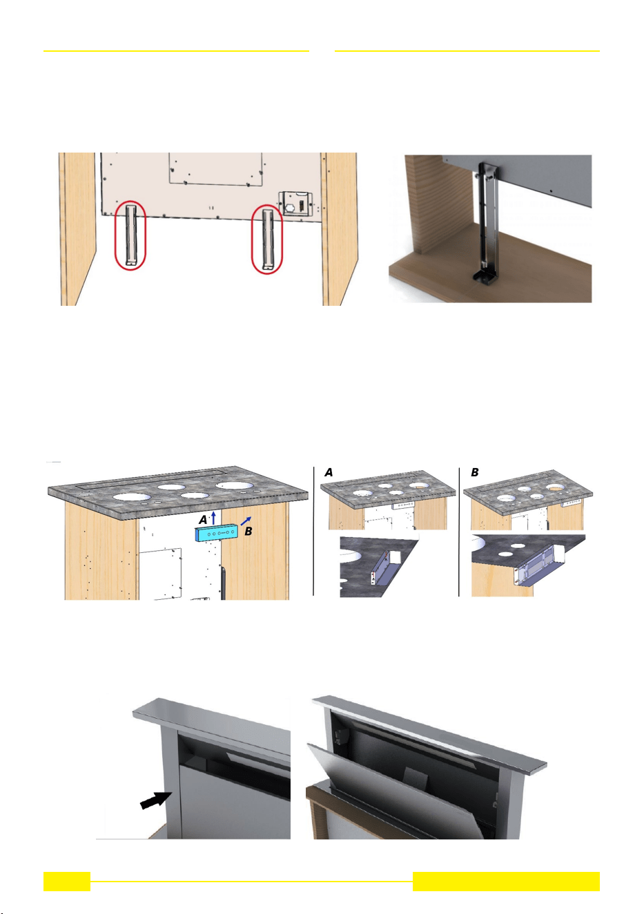
8. After completing the installation, fasten the push-button panel below the top immediately behind the
cabinet doors (see g.18A for central installation, g.18B for lateral installation). Before xing the push-
button panel, check that the doors are actually closed.
Fig. 18
Fig. 19
Connect the button cable to the electrical system and immediately after the product to the power grid, lift
the downdraft, remove the door lock and then open the door (g. 19).
14
SU-DD2-L
Fig. 17
If the downdraft is not aligned, act on the screws previously seen in g. 15 until correct alignment is
achieved.
Fasten the downdraft to the cabinet using the two brackets supplied (g. 17).
Having veried the correct position and stability of the product, proceed to glue the additional surface
on the top of the downdraft.
EN
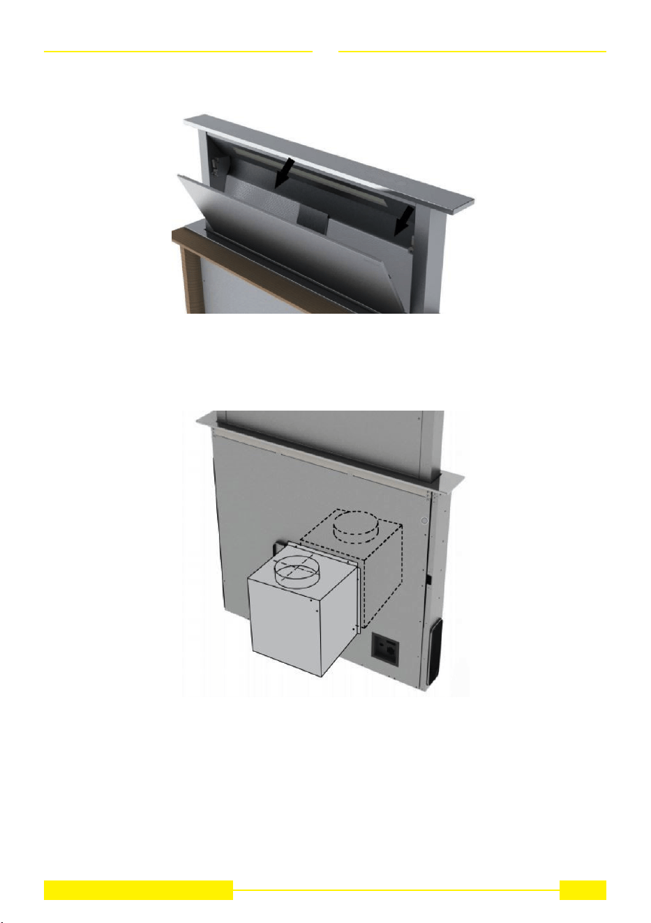
In the version of the Downdraft equipped with internal motor, install the power unit orienting the air outlet
to the desired position, either downwards or upwards (Fig. 21). The motor can be installed either on the
front or rear side of the downdraft.
15
SU-DD2-L
Fig. 21
After having installed the motor, connect the air ducts.
Position the lters (g. 20).
Fig. 20
EN
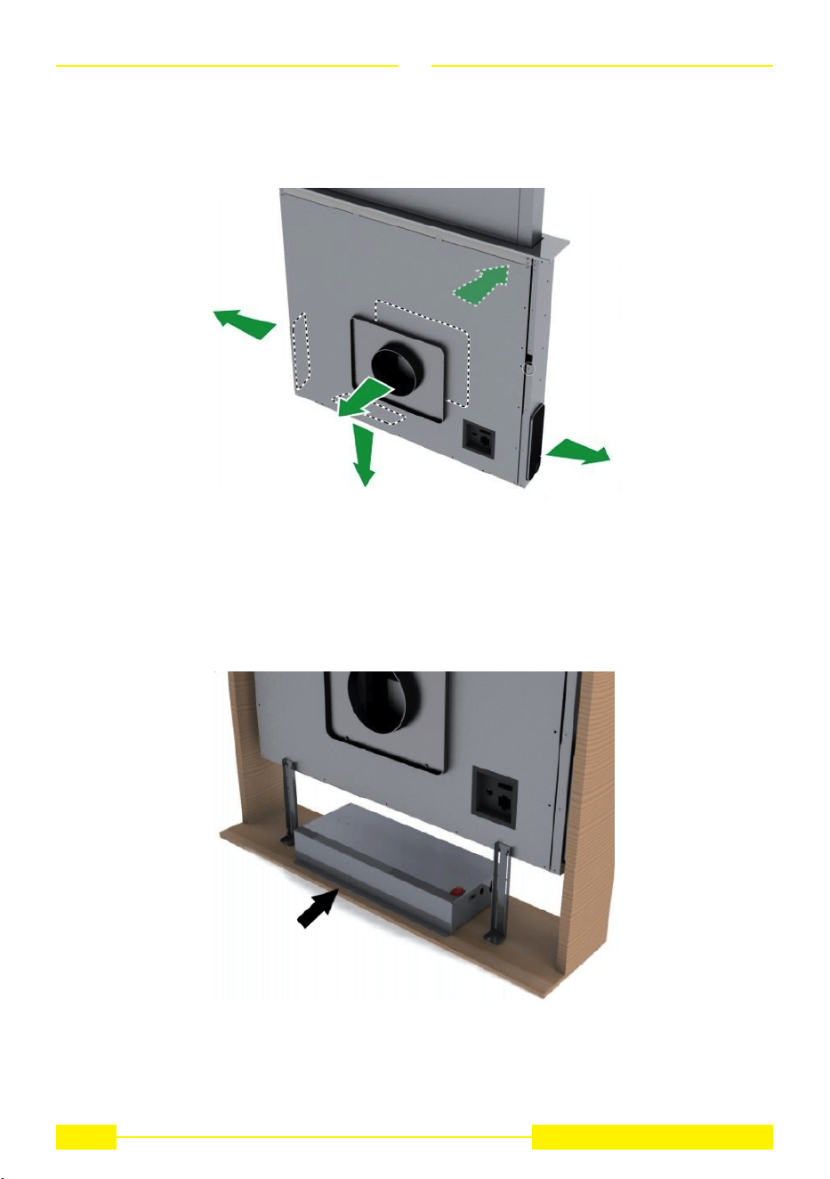
9. For versions with external motor, place the suctioning unit (external motor) in a suitable area and t
the exhaust air ue as illustrated. Then t the air outlet ducts between the external motor and the down-
draft. Select an air outlet from the ve possibilities (Fig. 22) and t the union supplied with the appliance.
Fig. 22
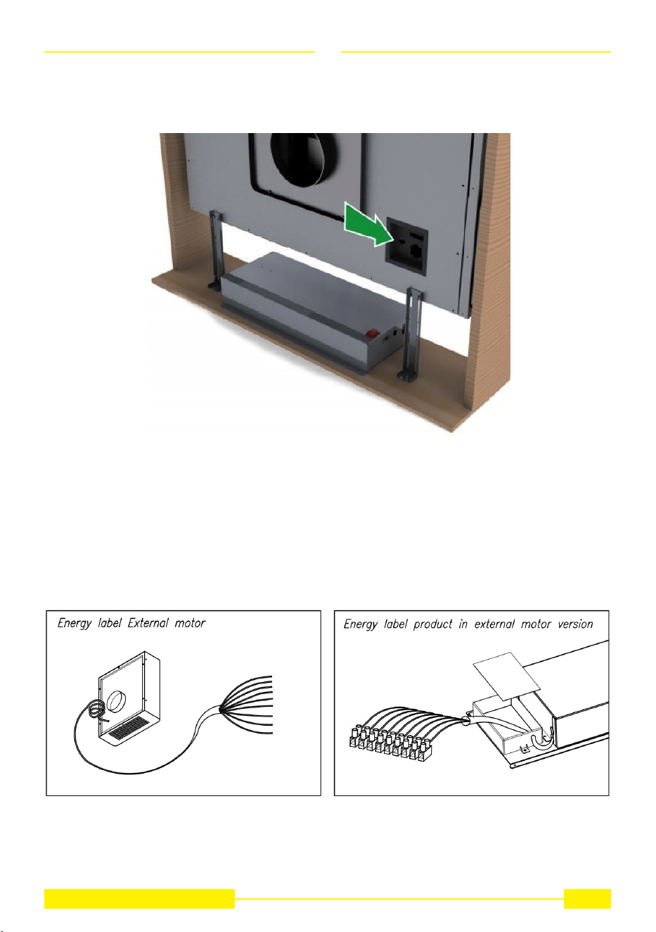
10. Place the metal box with the electronic components in an easily reachable area for eventual techni-
cal assistance operations. (Fig.23),
Fig. 23
16
SU-DD2-L
EN
connecting the three connectors (9 pole connector for the actuator control and the safety control, 4 pole
connector for led lamp turn on and push-button connector) (Fig. 24).
17
SU-DD2-L
Fig. 24
11. Connect the internal motor or te eternal motor’s cable to the terminal board found in- side te plastic
box of the downdraft wiring.
Make sure to respect the colors of cables when performing the electrical connection (Fig. 25).
Fig. 25
12. Power the cookerhood.
EN
Fig. 26
This appliance is intended to suck cooking fumes, greases and steam. It has been designed to work in
both suctioning mode, with outside evacuation, and ltering mode.
Outside - discharge version
The cooker hood can be mounted in the version with outside discharge of suctioned air: in this case it
is necessary to connect the exhausting channel to the outside (exhausting pipes are not supplied with
the products.)
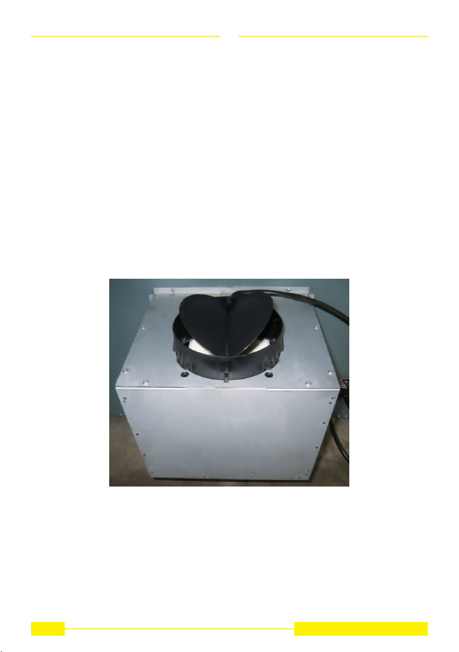
Non-return valve blockage
WARNING
Before connecting the air exhaust hose, make sure that the non-return valves can rotate freely. (Fig.26)
18
SU-DD2-L
HOW TO USE THE COOKER HOOD
EN
In case of outside air discharge installation, t a non-return valve to prevent wind and back air from
entering.
19
SU-DD2-L
Fig. 27
Filtering mode
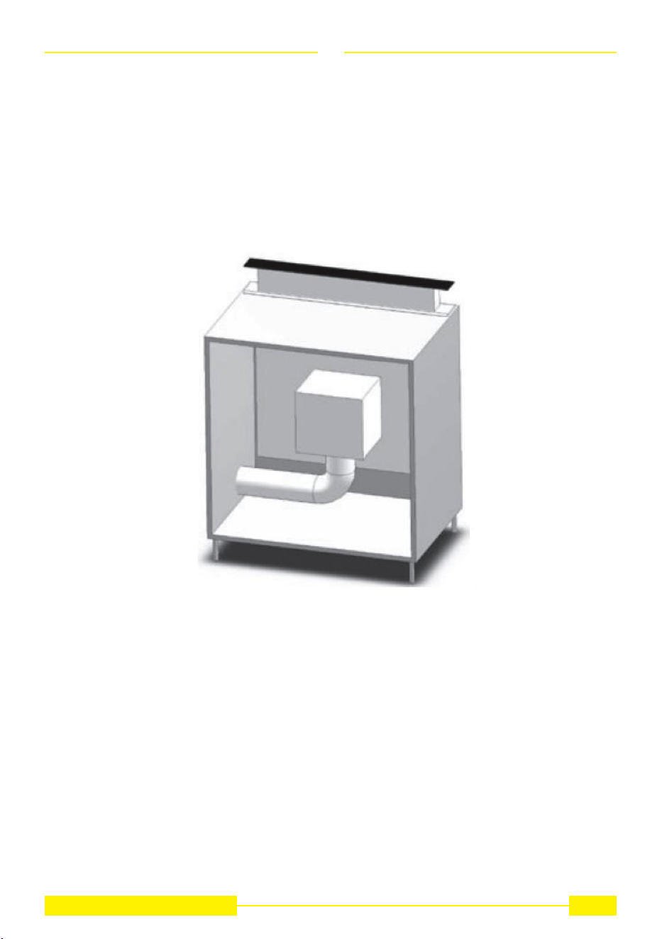
In case fumes and vapour cannot be evacuated outside, the appliance can be used in the ltering mode.
Activated charcoal lters are required for this type of cooker hood. Air recycled through the charcoal l-
ters is recirculated into the kitchen, thanks to a duct conveying the air on one side of the cabinet (Fig.27)
CAUTION
Installation must comply with the regulations in force regarding the ventilation of enclosed environments.
In particular, discharged air must not be conveyed into a duct used for fumes discharge or discharge
from appliances using gas or other combustible materials. The use of discontinued ducts is not allowed
without the approval of a qualied technician.
EN
GREASE FILTER REMOVAL, MOUNTING THE ACTIVATED CHARCOAL FILTER
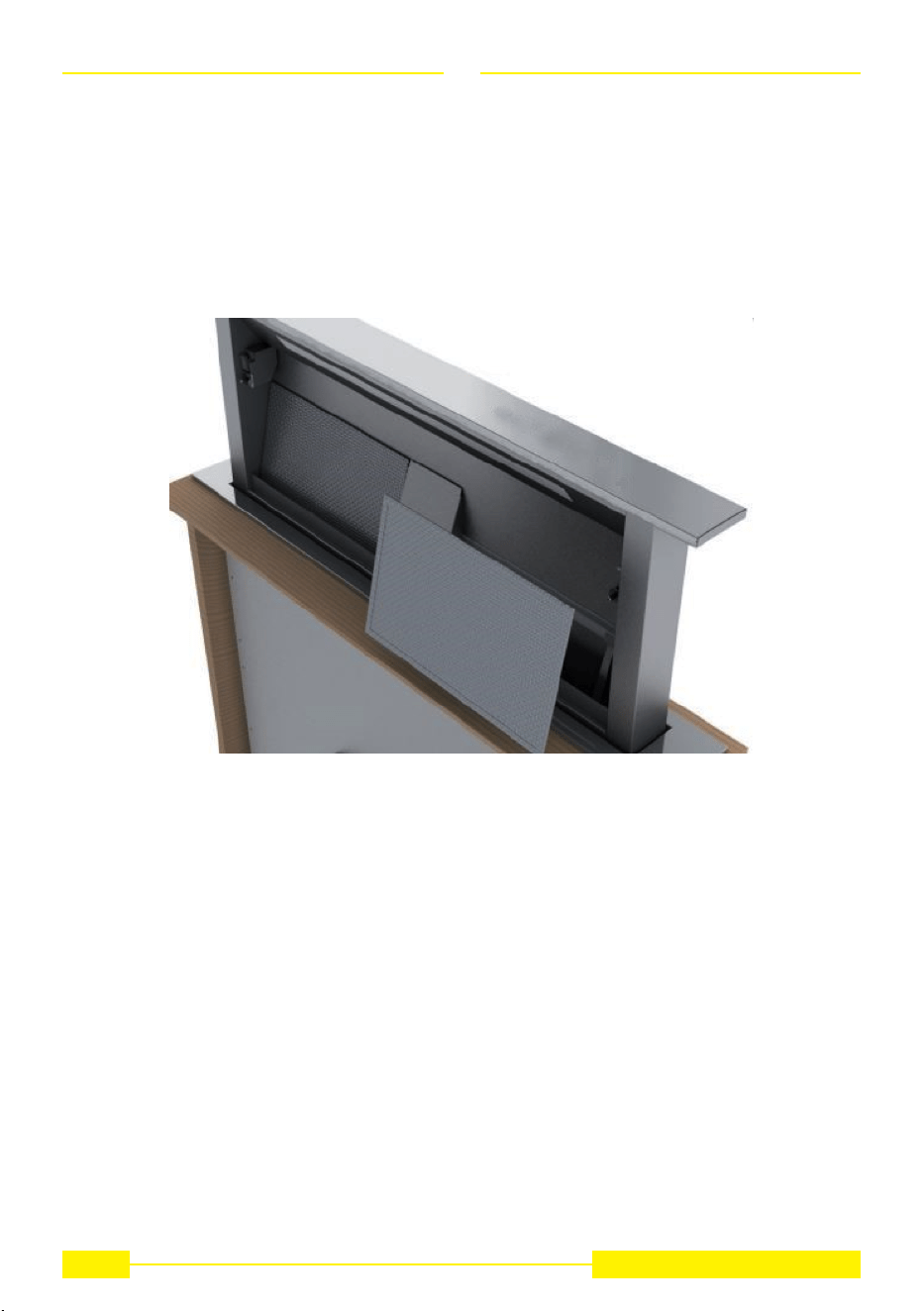
The removal and tting of the grease and carbon lters need to be carried out with the downdraft in the
open position. To open the downdraft, push the key. Then remove the front panel, pushing the upper part
of each side at the same time. The panel will rotate forwards to make it possible to access the grease
lters (Fig. 20). Remove the grease lters to access the carbon lters (Fig. 28). The replacement of the
charcoal lters has to be carried out accordingly to the effective use of the Downdraft, and in any case
at least once every 6 months.
Fig. 28
WARNING
After having replaced the lters, reinstall the front stainless steel pan’el, otherwise the Downdraft is not
enabled to function.
20
SU-DD2-L

EN
ELECTRICAL CONNECTION OF THE COOKER HOOD
WARNING
Place the metal box containing the electronic components at a distance of no less than 65 cm from gas-
operated cook tops or in any case, 65 cm from the suctioning surface of the cookerhood.
NOTA
We recommend installing the metal box containing the electronic components at least 10 cm above oor
level and at a suitable distance from all heat sources (e.g. oven sides or cook top).
CAUTION
This appliance is tted with an H05 VVF 3 conductor, 0.75 mm2 (neutral, phase, and ground) power
cord. This can be connected up to a 220 - 240 V mono-phase electrical network through a CEI 60083
approved power socket, which must remain accessible after installation, in compliance with installation
regulations. We decline any responsibility in case of accidents caused by a lack of ground connection or
incorrect ground connection. The appliance must be fed through a differential protection device (RCD),
with a nominal residual current not exceeding 30mA. If the power cord is damaged, call the after-sales
service to avoid any risk.
WARNING
The downdraft connection to the electrical network must be carried out only by professional and qua-
lied technicians. The downdraft must be connected to a properly installed and suitable electrical net-
work. The electrical system must comply with VDE0100 standard.
DANGER
If the cooker hood presents any anomaly, disconnect the appliance or remove the fuse corresponding
to the appliance power disconnecting line. If the appliance has no plug or if the plug is not easily acces-
sible, then a device needs to be tted to cut it off from the electric network; this device must have an
opening distance between contacts on all poles of at least 3 mm.
ELECTRICAL CONNECTION
NOTA
This appliance complies with the European Directives 2006/95/EC (Low Voltage Directive) and
2004/108/EC (Electromagnetic Compatibility).While installing the appliance and carrying maintenance
operation, make sure it is disconnected from the electrical network or the fuses are cut out or removed.
Check that:
• Power is enough.
• Feeder lines (mains) are in good conditions.
• The cables diameter complies with installation regulations.
21
SU-DD2-L

EN
HOW THE COOKER HOOD WORKS
22
SU-DD2-L
A: Light ON/OFF key
The light switches on and off only when the carriage is fully OPEN. Pressing this button with the carriage
closed will cause the carriage to open and then the light will switch on.The button also serves to switch
off the light if it is on.
B: ON/OFF key
This starts the extraction carriage upward movement and when it is fully open, it sets the second ex-
traction speed. With the carriage open: it switches off the motor and if on, the light; then it retracts the
extraction carriage.
C: (-) Key
This reduces the speed of the extractor motor from the 4th speed until the motor switches off, without
closing the pull-out carriage.
D: Indicators
• This signals the speed setting, by only the relevant LED switching on.
• This signals that all lters have been saturated by all LEDs switching on.
E: (+) Key
This increases the speed of the extractor motor, from 1st to 4th speed, without moving the extractor
panel.
F: Timer
10 min after setting, it serves to stop the extractor motor, close the carriage and switch the lights off, if
they are on. The set function is signalled by the ashing LEDs “D” for the set speed. The timer can be
cancelled by pressing the key again.
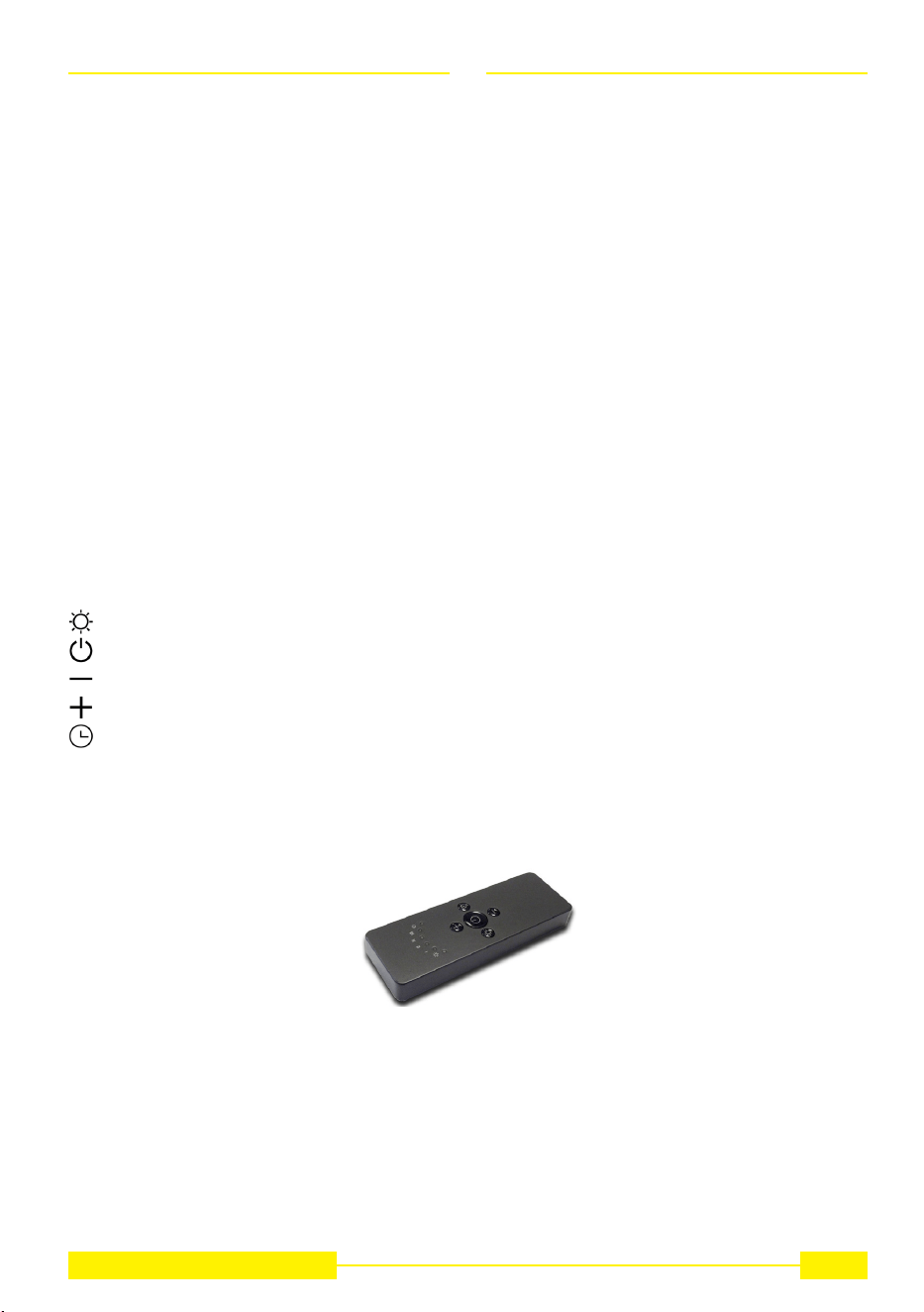
Remote control (Fig.11).
channel radio control for cooker hood remote.
At rst ignition, keep pressed the lighting button for 5 seconds.
RC001
RADIO CONTROL
Radio control used for the remote operation of ducted cooker hoods.
TECHNICAL DATA
- Alkaline battery powered: 12 V mod. 27A
- Operating frequency: 433.92 Mhz
- Combinations: 32.768
- Max. consumption: 25 mA
- Operating temperature: -20 ÷ + 55 °C
- Dimensions: 130x45x15 mm.
OPERATING DESCRIPTION
The transmitter is equipped with 5 buttons for cooker hood management, as specied below:
: Light ON/OFF command.
: Motor ON (speed level 1) / OFF command.
: Reduce speed.
: Increase speed.
: 10-minute timer.
INITIAL OPERATING CONDITION
The manufacturer supplies the radio control unit ready to be used with codes preset in the Factory
OPERATION MODE
Standard conguration:
Standard conguration requires all “cooker hoods – radio control - system” to be provided with the same
transmission code. In the event two cooker hoods – radio control system are installed in the same room
or nearby, each system may affect the operation of the another. Therefore, the code of one radio control
system must be changed.
23
SU-DD2-L
EN
IF THE PRODUCT WORKS WITH SUPPLIED REMOTE CONTROL
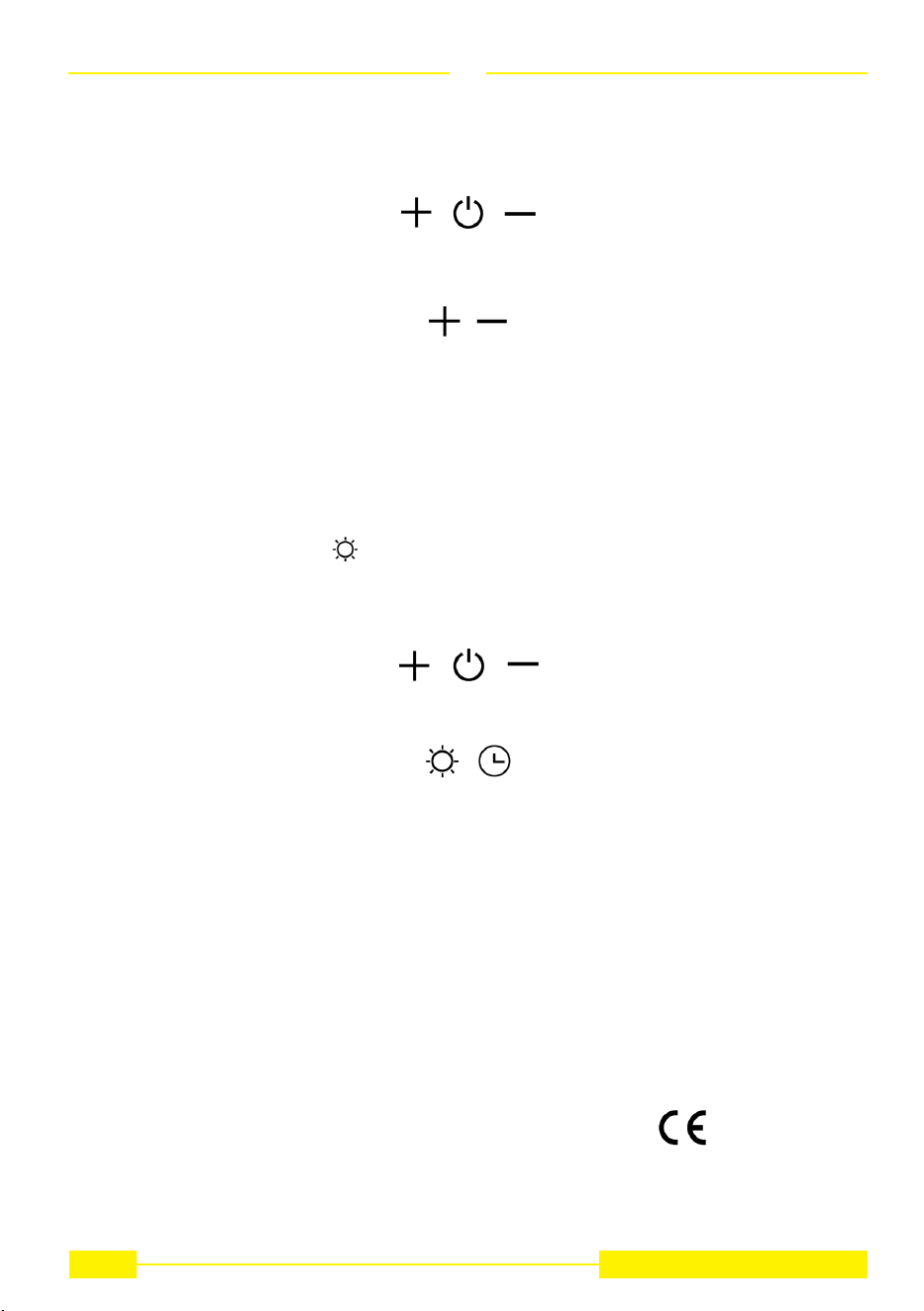
Generating a new transmission code:
The radio control system is provided with preset codes. Should new codes be required, proceed as
follows: Press simultaneously buttons:
for two seconds. When Leds light on, press buttons:
(within 5 seconds). Leds ashing 3 times indicate the procedure is completed.
WARNING! This operation deletes permanently the preset codes.
Learning the new transmission code:
Once the transmission code is changed in the radio control unit, the electronic central unit of the cooker
hood must be made to set the new code in the fol- lowing way:
Press the main power-off button of the hood and then restore power to the electronic control unit. Within the next
15 seconds, press the Liight Button to synchronise the central unit with the code.
Reset of the Factory conguration:
To restore the Factory conguration, follow the procedure described below: press simultaneously but-
tons:
for 2 seconds. When Leds light on, press buttons:
(within 5 seconds). Leds ashing 6 times indicate the procedure is completed.
WARNING! This operation deletes permanently the preset codes.
Emergency button:
In the event that the radio control does not work, use the emergency button to switch the appliance off.
After any necessary repairs have been performed, reset the emergency button.
WARNING
The battery should be replaced every year to guarantee the optimal range of the transmitter.
To replace the exhausted battery, take the plastic lid off, remove the battery and replace it with a new
one, observing the correct battery polarities.
Used batteries should be discarded in special collection bins.
The below product:
RC001 Radio Controll
complies with the specications set out in the Directive RED 2014/53/EU.
EN
24
SU-DD2-L

EN
Other functions:
Automatic turn off:
After 4 hours of continuous working from the last setup, the appliance turns off and closes automatically.
Grease lters saturation:
After 30 hours of working, the speed indicators “D” will all ash simultaneously, signaling the grease
lters saturation. To reset this alarm, hold down the “TIMER” button for at least 3 seconds, while the
carriage is open.
Calibration:
The cooker-hood carries out its self-calibration every 3 complete cycles of its extractable unit. By pu-
shing the “TIMER” key 6 times consecutively (MAX break between one push and the other is 3 sec.) all
the leds will ash and the calibration will be reset.
After the next 3 cycles the downdraft will carry out its self-calibration.
Stand-by:
When the extractable unit is closed and the light is switched off, the control panel, after 6 seconds, acti-
vates the Stand-by function, reducing the brightness of the leds.
This function can be stopped by pressing ON/OFF or LIGHT key.
Security system:
If there is an obstacle while the extractable unit is closing, the Downdraft stops closing and rises again
thanks to a security system.
WARNING
This operation has to be carried out by a specialized technician.
25
SU-DD2-L
EN
Careful maintenance ensures proper operation and good performances over time.
CLEANING
THE COOKER HOOD
The hood must be disconnected from the electrical network, both by unplugging the appliance
from the socket and activating the magnetic circuit breaker (safety cut-out), before removing
the metal grease lters. After cleaning operations, replace the metal grease lters as outlined
in the installation instructions.
CAUTION
MAINTENANCE HOW TO PROCEED?
ACCESSORY PRODUCTS TO
USE
External surfaces and
accessories
Do not use metallic scrubbers, abra-
sive products, or hard brushes.
To clean the external surfaces of the
cookerhood and the light housing
screen use only commercially avai-
lable household detergents diluted
in water. Then rinse with clean wa-
ter and dry with a soft cloth.
Active charcoal lter
with extractable unit
open
After 30 hours of operation, the
downdraft will signal the grease lter
saturation.
The saturation is signaled by the blin-
king of the 4 central leds.
To reset, hold down the timer button
for at least 3 seconds, while the car-
riage is open.
The grease lters can be washed by
hand or in the dishwasher. These l-
ters need to be cleaned on a regular
basis, because otherwise they may
represent a re risk.
Ret the grease lters and front
panel, making sure that the panis
properly tted at the sides so that it
it does not cause the downdraft to
stop operating.
Active charcoal lter
In the recirculation mode, the active
charcoal lter must be replaced pe-
riodically.
To remove the charcoal lter rst of
all it is necessary to remove the gre-
ase lter and then pull the plastic key
of the panel itself, in order to disen-
gage it from its seating.
Follow these steps in reverse order
to insert the active charcoal lter.
Replace the used charcoal lter on
an average of every six months.
26
SU-DD2-L
EN
OPERATIONAL
ANOMALIES
PROBLEM SOLUTION
The cooker hood
does not work...
The cooker hood has
low performances...
The cooker hood
stops in the middle of
operation.
Check that:
● There is not a power outage.
● A specic speed has actually been selected.
● The 9 pole connection is inserted properly.
● The red reset key, found over the electrical system box, is pushed.
● Make sure that the wires of the 9 pole connection are inserted properly
in the connector itself (during the connection phase, an excessive
pressure could bend the contacts).
Check that:
● The motor speed selected is sufcient for the quantity of fumes and
vapors present in the room.
● The kitchen is ventilated well enough to allow air for intake.
● The charcoal lter is not worn out.( ltering version cooker hood).
● The air outlet channel is free and compliant with paragraph no. 2.
● The non-return valves of the suctioning unit are free to rotate.
Check that:
● There is not a power outage.
● The omnipolar device has not tripped.
AFTER SALES SERVICE
Any maintenance operation on your appliance should be carried out by:
● Either your retailer;
● Or another qualied professional technician, authorized for that brand.
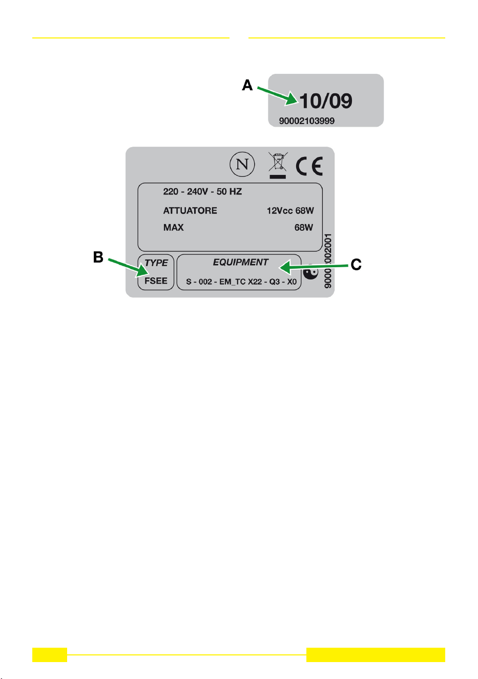
When calling, please mention the appliance details (Type Fig. 29A and equipment Fig. 29B and
production date Fig. 29C). This information is mentioned on the rating label and the production
date one placed on the lower side of the downdraft.
NOTA
27
SU-DD2-L
28
SU-DD2-L
EN
Fig. 29

29
SU-DD2-L
EN
The symbol on the product or on its packaging indicates that this product may not be treated as house-
hold waste. Instead it shall be handed over to the applicable collection point for the recycling of electrical
and electronic equipment. By ensuring this product is disposed of correctly, you will help prevent poten-
tial negative consequences for the environment and human health, which could otherwise be caused
by inappropriate waste handling of this product. For more detailed information about recycling of this
product, please contact your local city ofce, your household waste disposal service or the shop where
you purchased the product. This appliance is marked according to the European directive 2012/19/EC
on waste electrical and electronic equipment (WEEE).

Three Year Limited Warranty
YOU MUST REGISTER THE PURCHASE OF YOUR PRODUCT ON LINE AT
www.siriuscappe.com/usa/warranty.htm TO CONVALIDATE YOUR WARRANTY.
YOU CAN FIND THE DATA OF YOUR HOODS ON A LABEL INSIDE THE HOOD. JUST REMOVE
THE GREASE FILTER TO READ IT.
WARRANTY SERVICE
To qualify for warranty service, you must notify Sirius After sale service at the email address
stated below or call toll free USA 1-877-474-8770 and provide the model number, description of
the fault or defect and original date of purchase. Sirius reserves the right to request proof of ori-
ginal purchase. Sirius will at its sole option and discretion replace products that arrive damaged
through shipping, provided shipping damage is reported as stated above WITHIN 5 BUSINESS
DAYS OF RECEIPT of the shipped product or products.
ONE YEAR SERVICE REPAIR WARRANTY:
During the rst year from date of original purchase, Sirius will, at its option, repair or replace, without
charge, any product or part which is found to be defective under normal use and service.
THREE YEAR PARTS WARRANTY:
For three years from date of purchase, Sirius will provide free of charge, non-consumable replacement
parts which are found to be defective under normal use and service.
WHO IS COVERED:
Sirius warrants to the original consumer purchaser of its products that such products will be free from
defects in materials and workmanship for a period of three years from the original date of purchase.
There are no other warranties, express or implied, including, but not limited to, implied warranties of
merchantability or tness for a particular purpose or application.
WHAT IS NOT COVERED:
This warranty does not extend to lters, lamps, batteries, ducts and ductwork components. This war-
ranty does not cover normal maintenance and service or products or parts which have been subject to
misuse, negligence, accident, improper maintenance or repair, faulty installation or installation contrary
to recommended installation instructions. The warranty on glass screens is limited to manufacturing
defects only and expressly excludes cracks and breakages as a result of faulty installation.
Labor and
associated costs associated directly with removal and re-installation are expressly excluded.
The duration of any implied warranty is limited to the three year period as specied for the express war-
ranty. Some states and provinces do not allow limitation on how long an implied warranty lasts, so the
above limitation may not apply to you.
Sirius S.P.A.
Zona industriale Berbentina 6/A
60041 SASSOFERRATO (AN)
ITALY
Sirius after sale service
Telephone (toll free): 1-877-474-8770
Email: Sirius@adcoservice.com
Register Online! www.siriuscappe.com/usa/warranty.htm

90009100299 EM 02/22