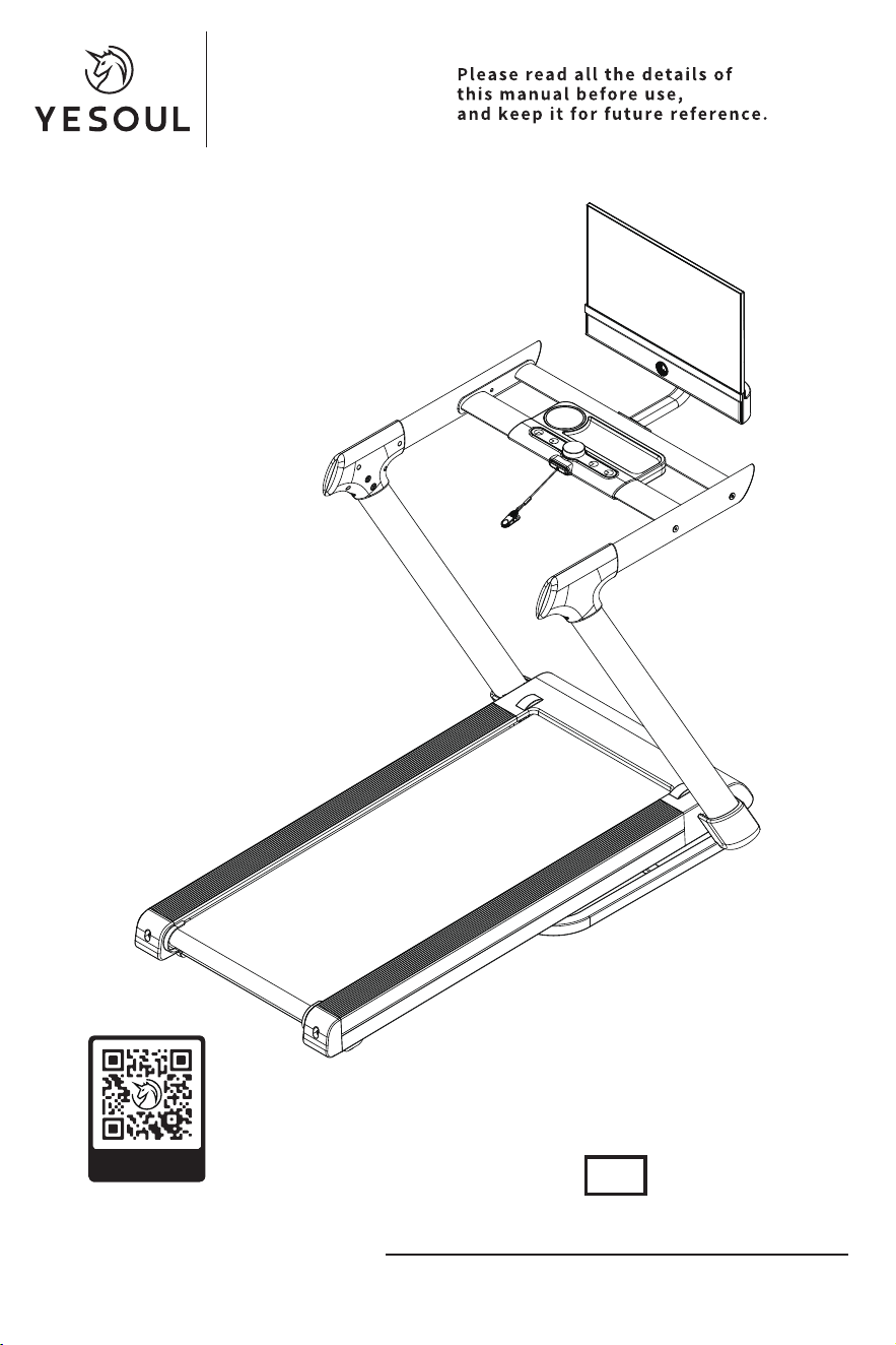
Scan for Installation Guide
T3S PLUS
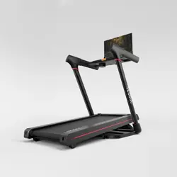
YESOUL READMILL
T3S PLUS Product Manual
TREADMILL
Scan the QR code to get the
installation guide video to watch
Product model:YS-TT3
Item NO.:T3SPLUS
EN

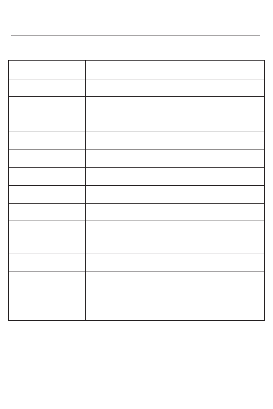
Product Specifications
50-60Hz
3.0HP(MAX)
1-14kph/0.62-8.7mph
155 ~ 190cm/61 ~ 74.8in
136kg/300lbs
EN ISO 20957-1:2013 EN ISO 20957-6:2010
Unfolded size: (Length) 1434mm×(Width) 731mm×(Height) 1441mm
Folded size: (Length) 875mm× (Width) 731mm×(Height) 1441mm/
Unfolded size: (Length) 56.5in×(Width) 28.8in×(Height) 56.7in
Folded size: (Length) 34.5in× (Width) 28.8in×(Height) 56.7in
(Length)1150mm×(Width) 450mm/
(Length)45.3in×(Width) 17.7in
Treadmill: V5.0, Speaker: V5.2
110V
58.3kg/128.5lbs
65.7kg/148.8lbs
iOS 12.0 and above, Android 5.1 and above (inclusive)Supported software version
Bluetooth
Rated voltage
Rated frequency
Rated power
Speed
Applicable height
Net weight
Bluetooth® wireless technology
Wireless connection method
Gross weight
Rated maximum load
Running surface area
Product dimensions
Executive standard
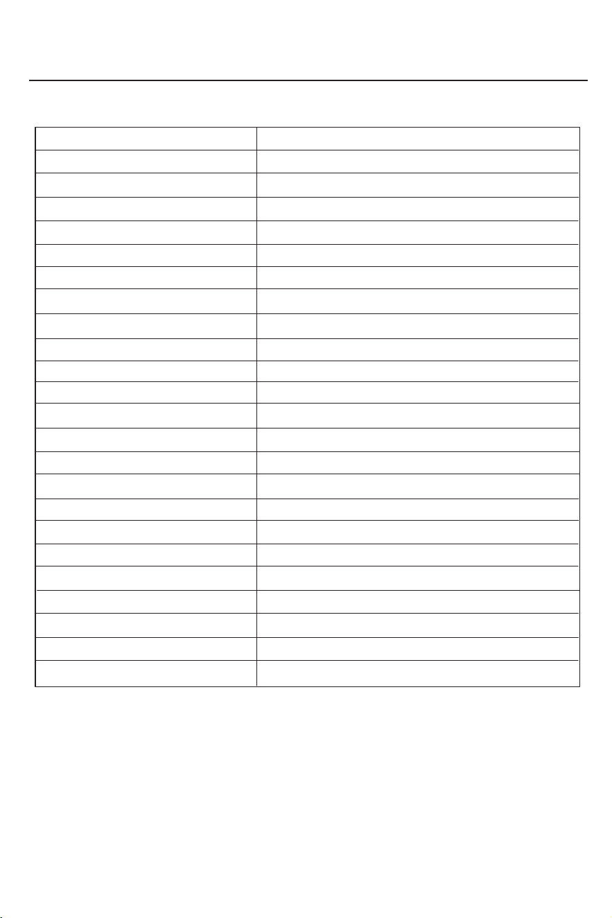
Monitor specifications
Panel type
Curvature
Proportion
Size
Backlight type
Display size (H*V)
Resolution
Refresh rate
Brightness
Default color temperature
Contrast
Color number
Color gamut
Viewing angle (horizontal/vertical)
Responding speed
Interface version (HDMI/DP)
Speaker specifications
Input voltage
Indicator mode (power on, standby)
Storage temperature
Operating temperature
Operating humidity
Storage humidity
Control method
VA
Flat screen
16:9
21.5 inches
Side entry LED
476mm*268mm
1920*1080
75Hz (Max.), 60Hz (Typ.)
200cd/m2(Typ.), 150cd/m2(Min.)
6500K
3000:1(Typ.)
16.7M
72% (Typ.);65% (Min) NTSC
178°
7ms
HDMI/Audio Out/DC IN+2USB+serial port
None
DC input: 24V
Green when starting up, breathing green when standby
-20°C ~+55°C
5°C ~ +40°C
20% ~ 80%
20% ~ 80%
5 physical buttons
Important Safety Instructions
◆ Wear appropriate sportswear and shoes before exercising. Ensure that clothing is
properly fastened or zipped to prevent it from getting caught in the treadmill.
◆ Do not carry hard objects in your pockets while using the treadmill, as this may cause
accidents or injuries.
◆ Do not use the treadmill after consuming alcohol, as it may lead to accidents or
injuries.
◆ When turning on the treadmill, stand on the non-slip side rails.
◆ Only one person is allowed on the treadmill when it is in operation.
◆ Do not eat or engage in other activities while using the treadmill.
◆ Ensure that people stay at a safe distance from the treadmill during use to prevent
accidents or injuries from falls.
◆ Check that the treadmill is placed on a stable surface before use.
◆ Verify that the treadmill functions properly before use. Check if the column covers
and handlebars are securely locked. If they are loose, injury may occur.
◆ Attach the safety key clip to your clothing before use to ensure the treadmill stops
safely in case of an emergency.
◆ Before working, start by walking slowly on the treadmill with your left foot following
the belt direction. Once comfortable, begin working while maintaining proper posture.
◆ Maintain a safety clearance of 2000x1000mm/78.7x39.3in behind the treadmill while
in use.
◆ Adjust speed gradually based on your capacity. Do not suddenly increase speed above
3.8kph/2.3mph to prevent falls and injuries.
◆ Do not jump while working to avoid falling or injury.
◆When adjusting the incline, stand on the side footboards of the treadmill with both feet
and start exercising only after the adjustment is complete.
◆Please avoid making significant adjustments to the incline while the machine is
operating at high speeds to prevent loss of balance and falling.
◆When using the high incline mode, please adjust the speed according to your physical
fitness to avoid overexertion.
◆ Do not jump off the treadmill after exercising to prevent accidents.
◆ To stop the treadmill after exercise, pull the safety key down or press the stop button.
◆ After exercising, turn off the treadmill's power switch and unplug it.
◆ The treadmill is designed for indoor use. Keep it dry, avoid water spills, and do not
place any foreign objects on it.
◆ Avoid prolonged excessive use, as it may damage the motor and controller and
accelerate wear on the running board and belt. Regular maintenance is recommended.
◆ Reduce dust levels and maintain proper indoor humidity to prevent static interference
with the console or controller.
Warning! This product is a plug-in product.
Please read the following details on the safety
precautions for the treadmill and properly use it.

Important Safety Instructions
◆ Do not use the treadmill outdoors. This product is intended for home fitness use and is
not a medical device.
◆ The treadmill should not operate continuously for more than 1 hour.
◆ Ensure proper indoor ventilation while using the treadmill.
◆ Always unplug the treadmill before moving it.
◆ Stop exercising immediately and consult a doctor if you feel unwell or notice any
abnormalities.
◆ People who lack regular physical activity should not engage in sudden, intense exercise.
◆ Store silicone oil out of children's reach after use to prevent accidental ingestion.
◆ Only qualified personnel should access the motor cover or roller housing.
◆ The treadmill should only be connected to an external circuit of at least 15A.
◆ Children must not use the treadmill or play near it. Guardians should ensure that
children do not operate the machine, as this may cause injury.
◆ Individuals with disabilities should avoid using this treadmill to prevent accidents or
injuries.
◆ Ensure a safe environment when using, storing, or moving the treadmill. Make sure no
people or pets are behind, under, or in front of the machine to avoid accidents.
◆ Do not use the treadmill if the casing is cracked, broken, or has exposed internal parts,
as this may result in injury or malfunction.
◆ Do not use or store the treadmill outdoors, near bathrooms, or in humid environments
to prevent moisture damage.
◆ Keep the treadmill away from direct sunlight and high-temperature areas (e.g., near
stoves, electric heating carpets) to prevent electrical hazards or fire.
◆ Do not attempt to disassemble, repair, or modify the treadmill yourself, as this may
cause mechanical failure and safety risks.
◆ Keep the treadmill console and body away from water or liquids to prevent electric
shock or fire hazards.
◆ If the treadmill malfunctions during operation, stop using it immediately and
disconnect the power.
◆ Contact your local distributor for repairs if a defect occurs. Do not attempt to dismantle
any parts of the machine.
◆ If you are undergoing medical treatment or belong to any of the following groups,
consult a doctor before using this equipment.
(1) Those experiencing back pain or who have suffered leg, back, or neck injuries, as well
as those with numbness in the legs, back, neck, or hands (e.g., herniated discs, spondylo-
listhesis, cervical spondylosis).
(2) People with degenerative arthritis, rheumatism, or gout.
(3) Individuals with osteoporosis or other bone disorders.
(4) Those with circulatory system diseases, such as heart disease, vascular diseases, or
hypertension.
(5) Individuals with respiratory disorders.
(6) Users of pacemakers or other implanted medical electronic devices.
(7) People diagnosed with malignant tumors.

Important Safety Instructions
(8) Those with blood clot disorders, severe aneurysms, acute phlebitis, or skin infections.
(9) Individuals with severe peripheral circulatory disorders or sensory abnormalities due
to diabetes.
(10) Individuals with open skin wounds.
(11) Individuals experiencing high fever (38°C or above) due to illness.
(12) Individuals with spinal abnormalities or curvature.
(13) Pregnant women, those who may be pregnant, or those currently menstruating.
(14) Individuals requiring bed rest or feeling unwell.
(15) Individuals in poor physical condition.
(16) Individuals using the treadmill for rehabilitation purposes.
(17) Individuals who feel physically unwell or believe that using the treadmill may worsen
their condition should avoid using it to prevent health risks or accidents.
◆ If an emergency occurs, grip the side handrails for support, lift your feet off the running
belt, and step onto the treadmill's side safety area.
◆If you notice any incline adjustment issues (such as jamming or failure to rise and lower),
stop using the treadmill immediately and contact customer service.
◆ When unplugging the power cord, hold the plug itself and pull gently to avoid damaging
the plug or power cable.
◆ Do not use the treadmill if the power cord or plug is damaged, or if the power outlet is
loose, as this may cause electric shock, short circuits, or fire hazards.
◆ Keep the power cord away from high-temperature objects to prevent overheating or
damage.
◆ Do not bend, twist, or forcefully pull the power cord, and do not place heavy objects on it
or trap it under furniture to prevent short circuits, electric shocks, or fire hazards.
◆ Ensure the power plug is free from foreign objects such as pins, dust, or moisture to
avoid the risk of electric shock, short circuits, or fire.
◆ Do not unplug the power cord or turn off the power switch while the treadmill is working,
as this may cause injury.
◆ Do not touch the power plug with wet hands to avoid electric shock or injury.
◆ When not using the treadmill, unplug it to prevent insulation deterioration due to dust
and moisture, which could lead to leakage or fire.
◆ Always unplug the treadmill before performing maintenance to avoid the risk of electric
shock or injury.
◆ If the treadmill malfunctions, stop using it immediately, unplug it, and contact a
professional for inspection and repairs. Continuing to use a faulty treadmill may cause
electric shock or injury.
◆ During a power outage, immediately unplug the power cord to prevent accidents or
injuries when power is restored.
◆ The power plug must be properly grounded and used with a dedicated circuit outlet to
prevent electrical interference with other appliances.
◆ This treadmill must be grounded to ensure electrical current flows safely to the ground
in case of a malfunction, reducing the risk of electric shock.

Important Safety Instructions
◆ The power cord is equipped with a grounding plug and must be inserted into a properly
installed and grounded outlet that meets local regulations.
◆ Incorrect grounding can result in electric shock hazards. If you are unsure about proper
grounding, consult a professional electrician.
◆ Do not modify the plug or outlet on your own. If necessary, have a professional
electrician install a suitable outlet.
◆ Use only the designated grounded plug for this equipment. Please make sure the
sockets match and do not use conversion sockets.
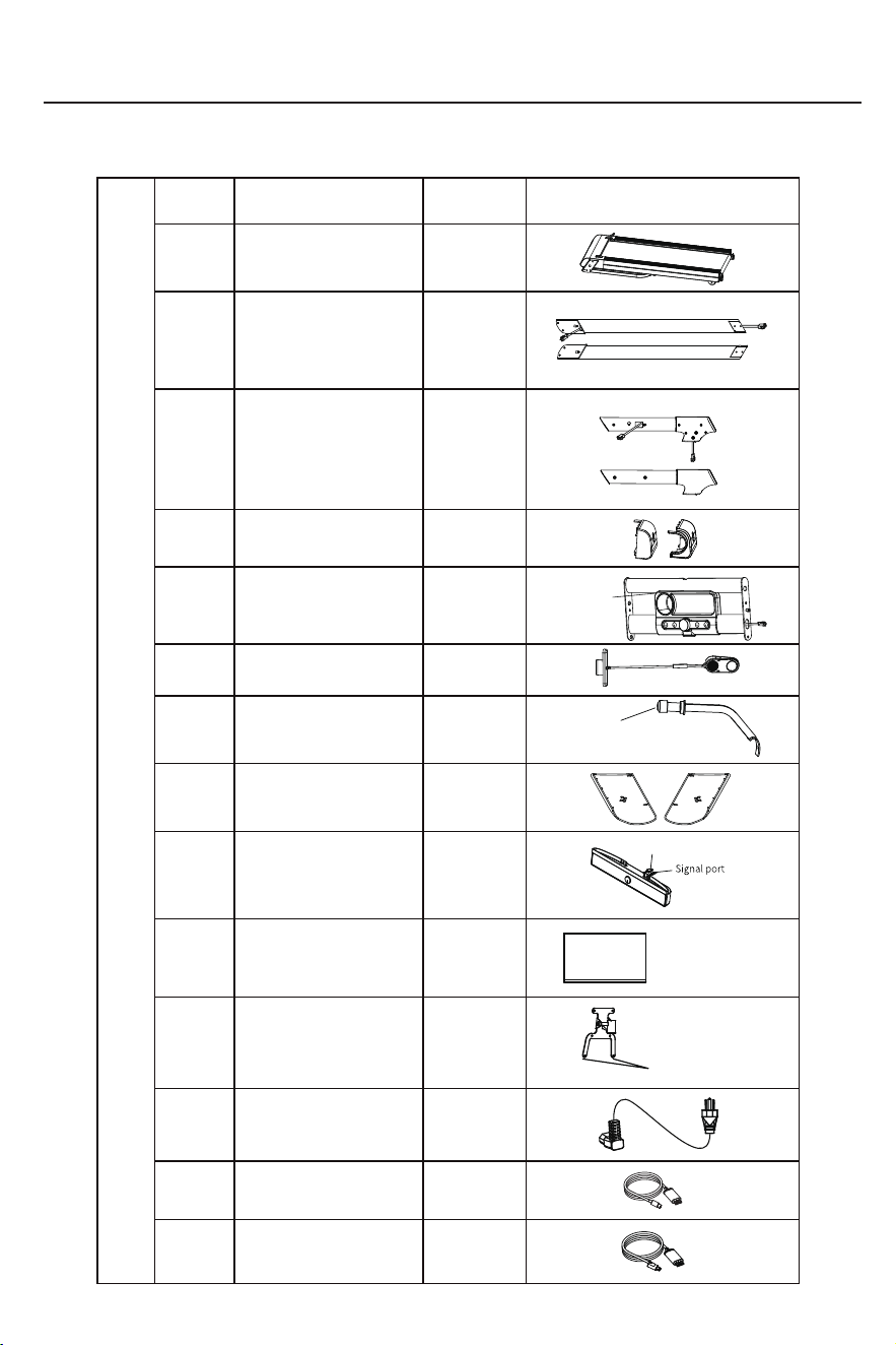
Installation Guide - List of Parts
STEP 1:Check of parts
1
⑭
⑩
⑨
⑦
NO.
Main frame ASM.
Console ASM.
Left/right upright
Left/right handlebar
Left/right
rear
corner guard
(
Left)
(Left)
(
Left)
(Right)
(Right)
(
right)
②
③
④
2
2
2
①
1
⑤
⑥
1
1
2
1
1
1
1
1
⑧
⑪
⑫
Monitor Stand
Left/right base
upright cover
Safety lock
Data cable
1×Prelocked hexagon
socket head screw M8×16/
washer M8
Speaker
Display screen
Screen fixing part
(Left)
(
Right)
⑬
1
Screen mirroring adapter
(Android)
Screen mirroring adapter
(IOS)
2×Hex socket flat
head screw M8×15
Name
Quantity
Picture
Parts List (Components List)
4×Pre-locked cross pan head
screws with pads M4×10
Power port
2×Pre-locked cross pan head
screws with pads M4×10
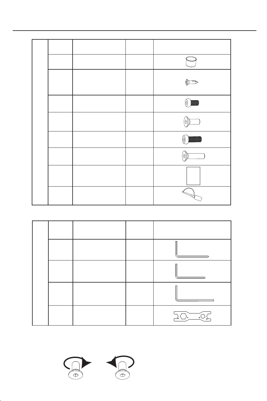
Installation Guide - List of Parts
*Some fixing screws are pre-locked on the corresponding parts at the factory. Please remove them
before installing the corresponding parts during assembly.Spare parts are subject to actual conditions.
Clockwise Counterclockwise
*Bolt fastening method: tighten clockwise, loosen counterclockwise.
C
D
A
B
1
1
1
1
NO.
Quantity Picture
Accessories List (Tools List)
NO.
2
1
Instructions
⑮
⑯
⑰
⑱
⑲
⑳
6
4
2
4
4
⑳
1
⑳
2
1
Multi-function wrench
13-15-17-19#
L-shaped head six
corner wrench 8#
Name
L-type cross head
hexagon wrench 6#
L-type cross head
hexagon wrench 5#
Cross recessed truss
head self-drilling
tapping screw
ST4.2×16
Instructions
Silicone oil bottle
Hex socket flat head
screw M8×15
Hex socket
countersunk
screw M8×25
Hex socket flat
head screw M8×20
Hex socket
countersunk
screw M8×40
Bottle Cage
Parts List (Components List)
Name
Quantity
Picture
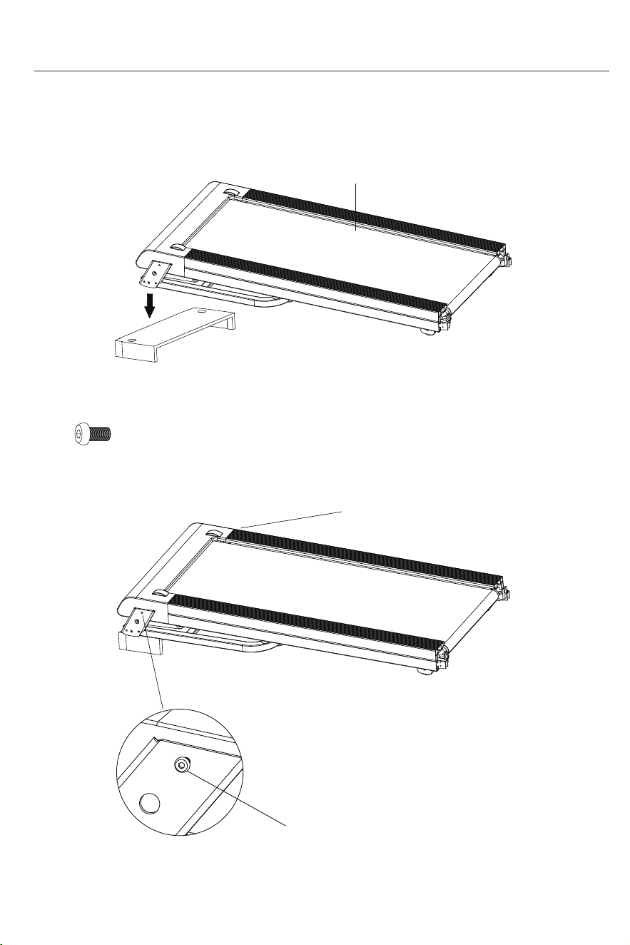
Installation Guide
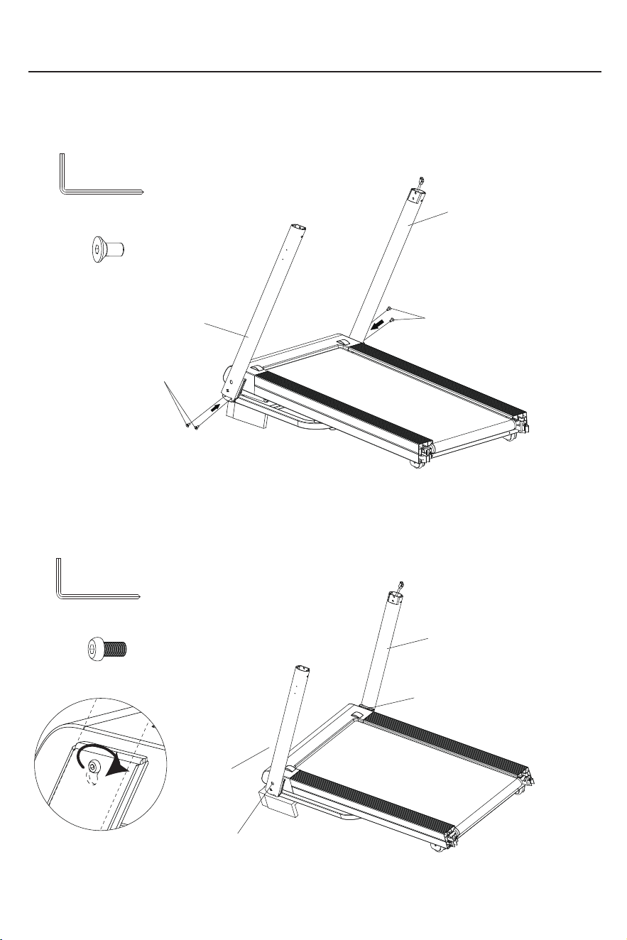
STEP 2: Install the Left and Right Uprights
1. Place a foam pad of appropriate height under the main frame ASM.①
2. Hand-tighten the hex socket flat head screws (M8×15) ⑰ into the holes located at the
top, on both the left and right sides of the running deck.
Hex socket flat head
screw (M8×15) ⑰ 2PCS
Main frame ASM.①
Hex socket flat head
screw
(M8×15)⑰
Hex socket flat head
screw
(M8×15)⑰
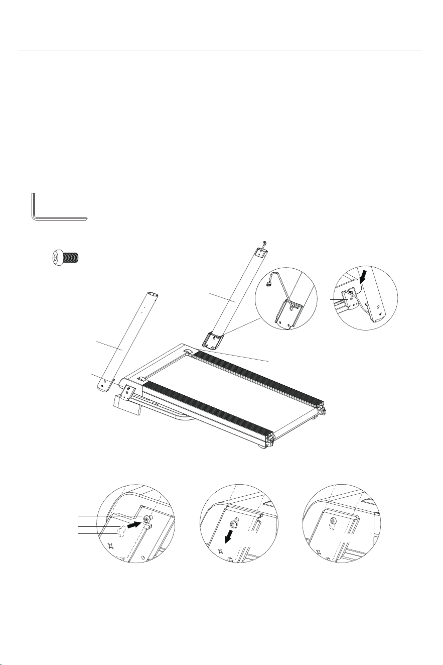
Installation Guide
3.(1)Pull the connecting wire slightly out from the wire-passing hole of the right upright ②
(Figure 1).
(2)As shown in (Figure 2), align the large holes on the inner covers of the left and right
uprights ② with the pre-installed hex socket flat head screw (M8×15) ⑰ and slide them
over the screws.
(3)While the hex socket flat head screw (M8×15) ⑰ is passing through the large hole
(Figure 3), simultaneously pass the connecting wire through the wire-passing hole of the
machine platform.
(4)Finally, press down the cover until the small holes lock onto the hex socket flat head
screw (M8×15) ⑰ (Figures 4 - 5).
If the shell cannot be
fitted, please use the
L-type cross head hexagon
wrench 5#(B) to slightly
loosen the hex socket flat
head screw (M8×15)⑰.
Right upright②
Left upright②
Hex socket flat head screw
(M8×15)⑰ 2PCS
L-type cross head
hexagon wrench 5#(B)
Small hole
Hex socket flat head
screw(M8×15)
⑰
Large hole
Fit in
Figure 5
Figure 2
Figure 4
Press
down
Complete
CAUTION: Do not crush
or damage cables
Hex socket flat head
screw (M8×15)
⑰
Hex socket flat head
screw (M8×15)
⑰
Figure 1
Figure 3
Note: Installation on one side must be completed continuously
(Steps 3, 4, and 5). Proceed to the other side only after one side
is fully assembled.
Installation Guide
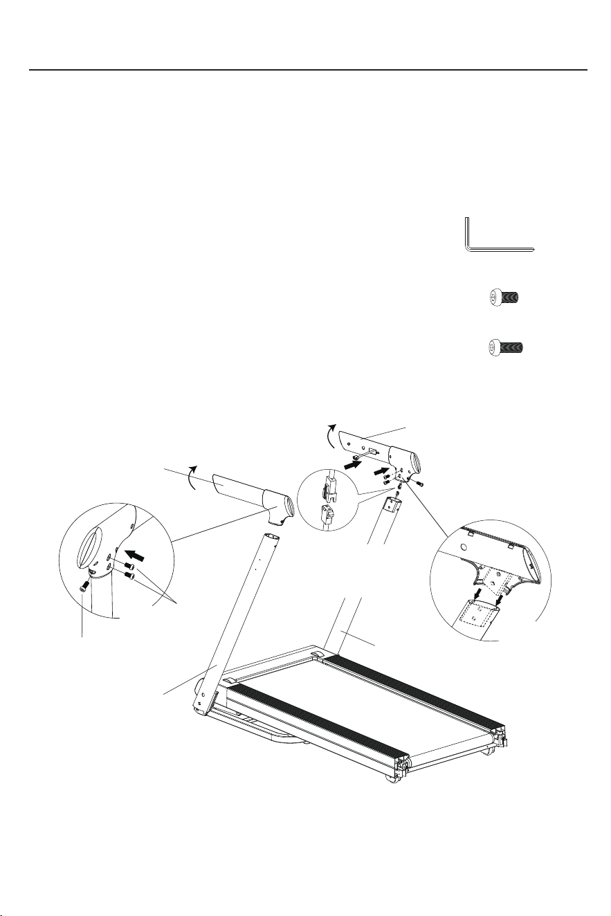
4.Use an L-type cross head hexagon wrench 5#(B) to tighten the four hex socket
countersunk screws (M8×25)⑱.
5. Using the L-type cross head hexagon wrench 5#(B), tighten both hex socket button
head screws (M8×15) ⑰.
Hex socket countersunk
screws (M8×25)
⑱
Hex socket countersunk
screws (M8×25)
⑱
Hex socket countersunk
screw (M8×25)⑱ 4PCS
Right upright②
Left upright②
L-type cross head
hexagon wrench 5#(B)
Hex socket flat head screw
(M8×15)⑰ 2PCS
L-type cross head
hexagon wrench 5#(B)
Left upright②
Right upright②
Hex socket flat head screw (M8×15)⑰
Hex socket flat head screw (M8×15)⑰
Installation Guide
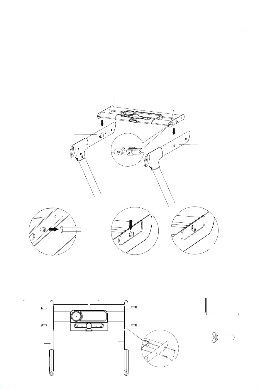
STEP 3:Install the Handlebar
1. Connect the right-handlebar signal wire to the right-hand upright post signal wire;
2. Insert the left and right handlebar③ into the left and right uprights ②, align them
with the holes on the upright posts, then securely tighten the 4 hex socket flat head
screws (M8×15) ⑰ and the 2 hex socket flat head screws (M8×20) ⑲ using the L-type
cross head hexagon wrench 5#(B).
Right upright②
Left upright②
Left handlebar③
Right handlebar③
Hex socket flat head
screw (M8×15)⑨ 4PCS
Hex socket flat head
screw (M8×20)⑲ 2PCS
Hex socket flat head
screws (M8×20)⑲
Hex socket flat head
screws (M8×15)⑰
If the hex socket flat
screw (M8×20)⑲
cannot be tightened,
please slightly lift this
part and align it with
the hole before
trying to tighten it.
Align the connector
interface and retract the
excess wire into the tube.
*Make sure the connector
direction is correct. Do not
force the connection!
L-type cross head
hexagon wrench 5#(B)
*Ensure insertion
into the
corresponding
cavity .
Apply firm
downward
pressure during
installation
Installation Guide
*Bolt fastening method: tighten clockwise, loosen counterclockwise.
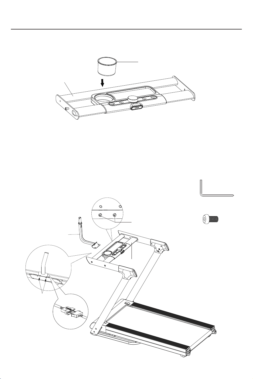
STEP 4: Install the Console ASM.
1.First, connect the signal wire of the electronic meter bracket to the signal wire of the right
handlebar;
2.As shown in Figures 1-3, align the large hole on the inner side of the left/right handlebar ③
with the screw on the side of the console ASM. ⑤, slide it over the screw, then press down
until the small hole locks onto the screw.
Right handlebar③
Left handlebar③
Console ASM.⑤
Align the connector
wires and retract any
excess wire into the
conduit.
* Note: Ensure correct
orientation of the
connectors; do not
force the connection!
Fit in
Figure1
Figure 2
Figure3
Press down
Small hole
Large hole
Complete
CAUTION: Do not crush
or damage cables
3. Manually align the console ASM.⑤ upright. Using an L-type cross head hexagon wrench 5#(B),
sequentially drive the four hex socket countersunk screws M8×40⑳ into the mounting slots on both
sides of the left/right handlebar③ in D-A-B-C order until a firm seating is achieved.
Hex socket
countersunk
screw M8×40⑳ 4PCS
Right handlebar③
Left handlebar③
Hex socket
countersunk
screw M8×40⑳
L-type cross head
hexagon wrench 5#(B)
Console ASM.⑤
A
B
C
D
Installation Guide
STEP 6: Install the Monitor Stand
STEP 5: Install the Bottle Cage
1. First, use the L-type cross head hexagon wrench 5#(B) to remove the 2 pre-installed hex
socket flat head screws (M8×15) from the electronic meter.
2. Then, connect the connecting cable of the monitor stand ⑦ to that of the console ASM. ⑤.
3. Next, align the 2 hex socket flat head screws (M8×15) with the 2 holes at the bottom of the
monitor stand ⑦, and screw them in using the L-type cross head hexagon wrench 5#(B) until
the monitor stand ⑦ is firmly connected to the console ASM. ⑤.
1. Align the bottle Cage ⑮ with the holes of the console ASM. ⑤, then insert it.
Console ASM.⑤
Bottle Cage⑮
Monitor Stand⑦
Console ASM.⑤
Hex socket flat head
screw (M8×15)
Align the connector
wires and retract any
excess wire into the
conduit.
WARNING: Ensure
correct connector
orientation; never force
the connection!
L-type cross head
hexagon wrench 5#(B)
Hex socket flat head
screw (M8×15)
Hex socket flat head
screw (M8×15) 2PCS
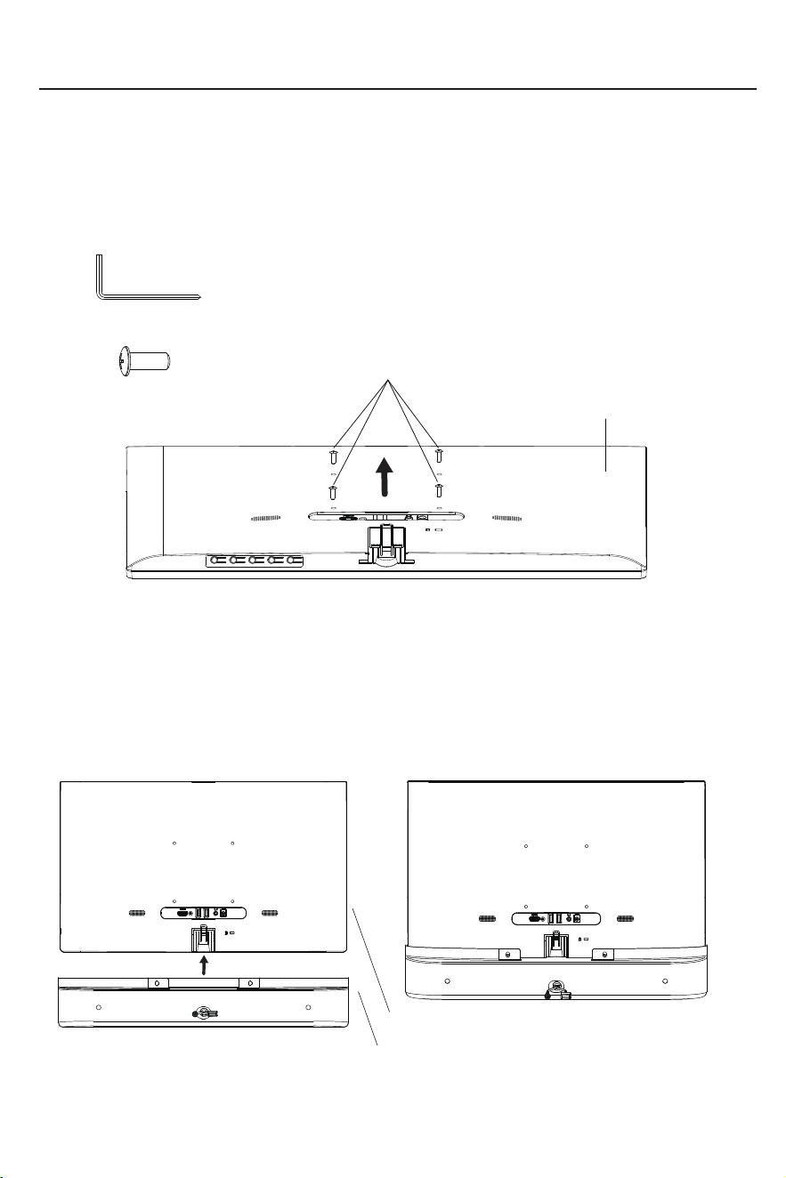
STEP 7:Installation ofscreen and speaker
L-type cross head hex wrench 6#(A)
Installation Guide
Speaker⑨
Screen⑩
1.Use the L-type cross head hex wrench 6#(A) to remove the phillips pan head
padded screws (M4×10)
pre-installed on the screen ⑩, as shown below;
* Please put the screen on the desk flatly. Do not collide with the screen with
hard objects to avoid screen damage!
Phillips pan head padded screws (M4×10)
Phillips pan head padded
screws (M4×10) 4PCS
2.After taking out the speaker⑨and placing it parallel to the screen⑩,
place the screen⑩ in the groove of the speaker⑨, as shown in the picture;
(Note: The speaker is equipped with a casing. When taking it out, ensure that
the front side of the carton is facing up to prevent damage)
Screen⑩
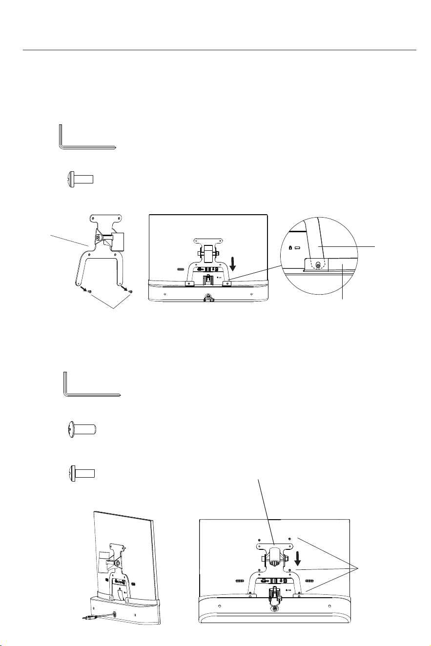
Installation Guide
Screen fixing part ⑪
Phillips pan head padded screws (M4×10)
Phillips pan head padded
screws (M4×10) 2PCS
Place one end of the long
sheet metal leg of the screen
flat and then insert it into the
inside of the audio plastic part
Long sheet
metal leg
Audio plastic
3. Take out the screen fixing part ⑪ and use L-type cross head hex wrench 6#(A) to remove
the phillips pan head padded screws (M4×10) pre-locked on the screen fixing part ⑪.
4.Place the screen fixing part ⑪on the back shell of the screen(Note: Place one end of
the long sheet metal leg of the screen flat and then insert it into the inside of the audio
plastic part.)
L-type cross head hex wrench 6#(A)
Screen fixing part⑪
Phillips pan head padded
screws (M4×10) 4PCS
5. Align the holes on the screen fixing part⑪ to the holes on the speaker⑨ and screen⑩,
pre-lock the six removed screws in sequence, adjust the parallelism between the screen
fixing part⑪ and the screen⑩, and then tighten all the screws clockwise;
Six screws
Phillips pan head padded
screws (M4×10) 2PCS
L-type cross head hex wrench 6#(A)
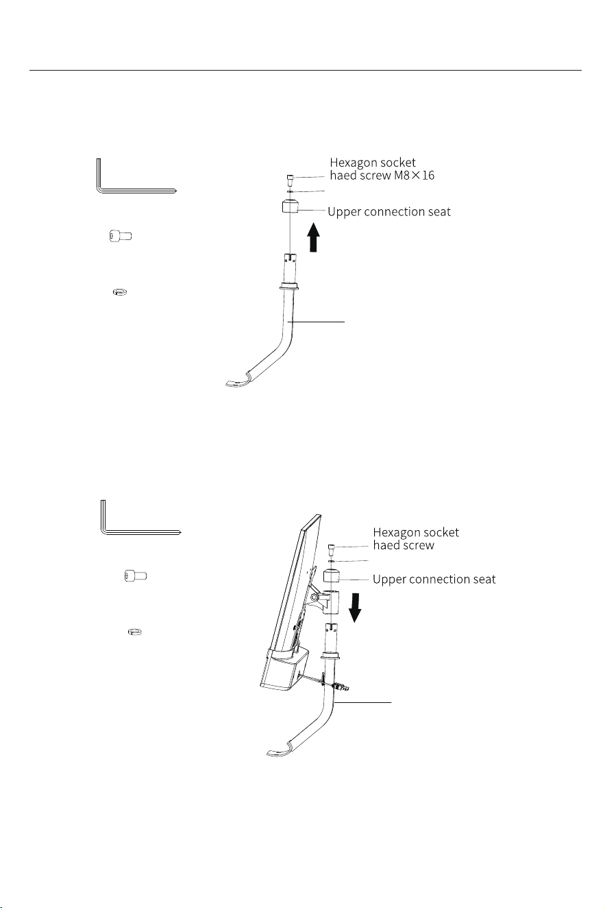
6.Loosen the hexagonal socket head screw(M8×16) and washer M8 pre-installed
on the monitor stand ⑦ with an L-type cross head hex wrench 6#(A), and then
remove the upper connecting seat.
7.Insert the screen and speaker components assembled in the previous step into the monitor
stand ⑦, then put in the upper connecting seat and hexagonal socket head screw(M8×16) and
washer in sequence, and use an L-type cross head hex wrench 6#(A) lock until secure.
Monitor Stand⑦
Installation Guide
Hexagon socket haed
screw (M8×16) 1PC
Washer M8 1PC
Hexagon socket haed
screw (M8×16) 1PC
Washer M8 1PC
Washer M8
Monitor Stand⑦
(M8×16)
Washer M8
L-type cross head hex wrench 6#(A)
L-type cross head hex wrench 6#(A)
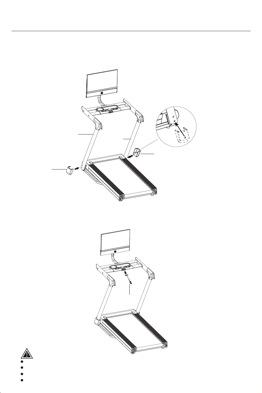
Installation Guide
STEP 8:Install the base cover
1.Align the left and right base decorative covers⑧ with the holes on the left and
right pillars②, then attach them to both sides of the base and snap them into place.
Right pillar②
Left pillar②
Left base
decorative cover
⑧
*Make sure the holes are aligned
Right base
decorative cover
⑧
STEP 9:Install the safety lock
1.Align the holes and install the safety lock⑥.
Before starting, please attach the safety key to clothing.
The machine will not work without the safety key inserted.
When the safety key is removed while walking, the machine will perform an emergency stop.
When not in use, please remove the safety key to prevent children from starting the machine.
Safety tips:
Safety lock⑥
Installation Guide
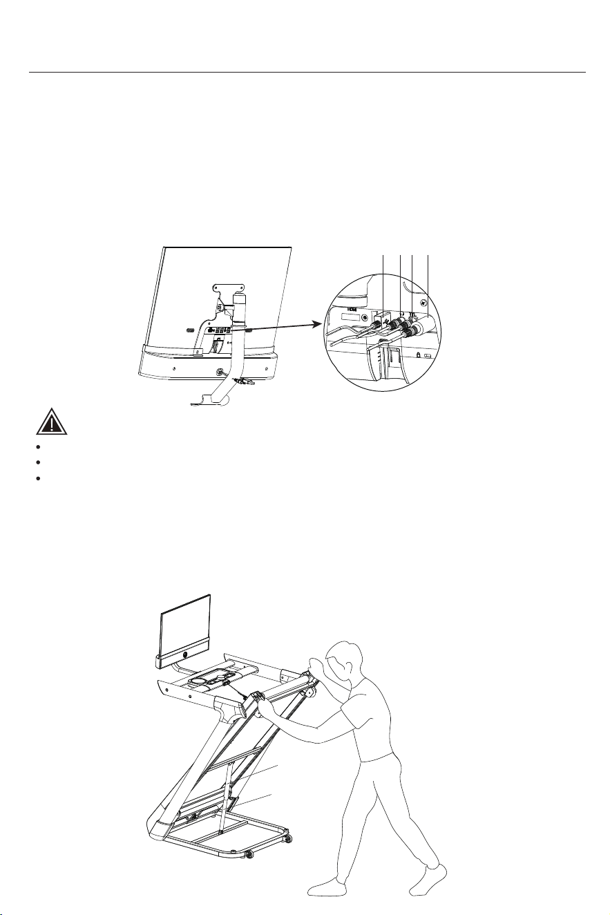
1. Insert the monitor's power port (a), signal port (b), audio signal port (d) into the jacks at the
bottom of the back of the plug them in tightly;(Pay attention to distinguish the colors and
specificationsof the sockets,plug the same color into the socket of the same color,
the power cord port must be tightened,do not insert it loosely)
2. Select the appropriate HDMI interface of the projection cabl the HDMI jack under the monitor;
(Note the difference between IOS and Android,for Android, the power interface needs to
be inserted into the socket,secure the excess wire with Velcro)
STEP 11:Install the right pillar connecting wire
1. Lift the treadmill to the upright position, and the non-return pipe will automatically get
stuck on the pneumatic cylinder (Verify that the anti-return tube is properly engaged
with the pneumatic cylinder.)
STEP 10:Install the base cover
Check
tube
Pneumatic
cylinde
c
d b
a
Safety tips:
Do not plug or unplug the monitor's interface without cutting off the power supply.
Please unplug the power when not in use.
Do not use this device during thunderstorms. Disconnect the power immediately!
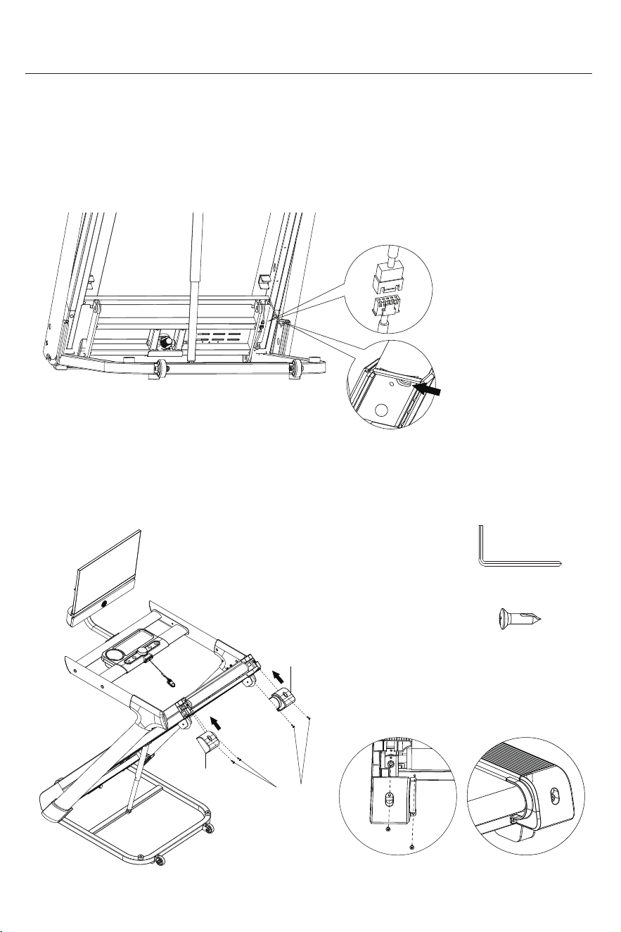
Align the connector interface,
check if it is correctly routed through
the hole,ensure the cable is not
pinched or damaged and retract the
excess wire into the tube.
*Make sure the connector direction
is correct. Do not force the connection!
Wiring hole
Installation Guide
2.Connect the right pillar signal wire to the body connecting wire, and retract the excess
wire into the tube.
STEP 12: Install the rear corner guard
2.Take out the left/right rear corner guard④ . Align them with the side strip in the direction
of the arrow and clip into place.Then, use the L-type cross head hexagon wrench 5#(B),
to tighten the cross recessed truss head self-Drilling tapping screw ST4.2×16 ⑯.
L-type cross head
hexagon wrench 5#(B)
Cross recessed truss head
self-Drilling tapping screw
ST4.2×16⑯ 4PCS
When installing
Once finished
Left rear corner
guard④
Right rear corner
guard④
Cross recessed
truss head
self-drilling
tapping screw
ST4.2×16⑯
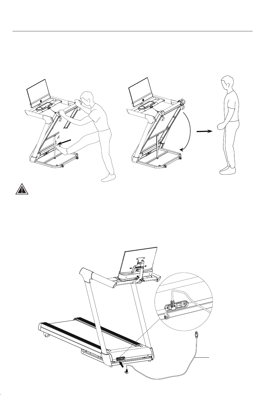
STEP 13:Install the power cable
Installation Guide
1. As shown in the figure, connect the power supply, turn on the power switch, and the
device enters the standby state.
Safety tips:
Please stay
away from
To prevent the equipment from dropping suddenly,
the main frame folds slowly. This is normal phenomenon.
2.Hold the treadmill with both hands and step on the anti-return tube with your feet.
(The person must stay about 1 meter away from the treadmill until the machine
is fully unfolded.)
Kick towards
the arrow
Data cable⑫
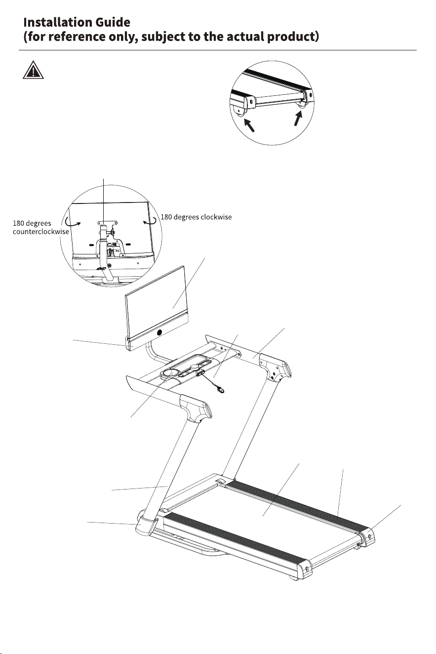
Display screen
Speaker
Water bottle holder
Before use, please check whether the
foot pad at the bottom of the treadmill
is placed stably and does not shake.
Safety tips:
Statement:
This manual includes a comprehensive introduction to the product's functions and
operating instructions as of the time of printing. However, due to ongoing improvements
in hardware, software, and design, there may be differences between this manual and
the product you purchased. In the event of any discrepancies in appearance, interface,
or color, please refer to the actual product.
Pillar
Treadbelt
Rear tail support
Safety lock
Handlebar
The screen supports 360 degrees of rotation,
allowing it to rotate 180 degrees clockwise or
counterclockwise.
(Use the L-type cross head hex wrench 6#(A)
to tighten or loosen as needed).
Edge strip
Base upright cover
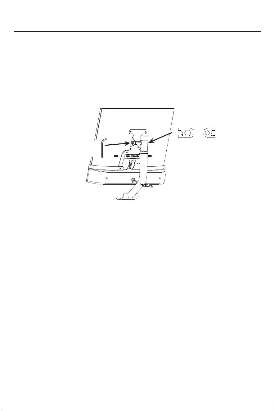
Multi-function wrench
13-15-17-19#(D)
L-shaped head six
corner wrench 8#(C)
Precautions
Check screen
After installation, check if the screen falls when turned upside down.
If it does, use the L-shaped head six corner wrench 8#(C) and the
multi-function
wrench 13-15-17-19#
(D) to tighten it as shown in the figure. (If the screen becomes
loose during use or if the joint needs adjustment, follow these steps to make the
necessary corrections)
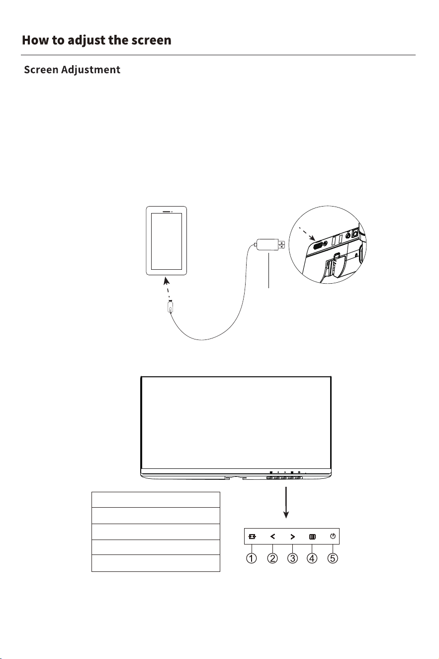
1. Version view/Exit
2. Reduce
3. Image ratio switch/Increase
4. Menu/Selection
5. Power switch
If you need to adjust the monitor screen, please use an L-type cross-head
hex wrench 6# (A) to remove the cross-head padded screws on the speaker
housing, place it up and down, remove the speaker, and then follow the button
operation instructions (as shown in the figure), make adjustments before
reinstalling the speaker.(Please ensure the screen mirroring device is connected
before adjusting the screen; otherwise, the OSD menu cannot be accessed.)
(1)Connect to the screen mirroring device
(2)Adjust the monitor screen
Wire outlet
Screen mirroring adapter
Mobile devices:
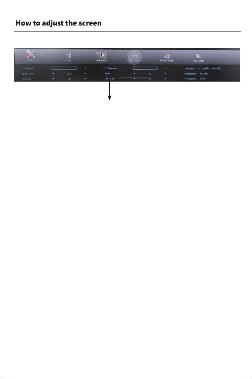
1.Make sure the monitor is powered on and in screen mirroring mode;
2.Press the "Menu" button to enter the OSD menu;
3.Press the "Decrease/Increase" buttons to select the desired option
(the unit switch option is under "Extra"), then press the "Select" button to enter;
4.Press the "Decrease/Increase" buttons to find "Km or mi", then press the "Select" button
to enter adjustment mode;
5.Press the "Decrease/Increase" buttons to choose the desired unit, then press the "Select"
button to save the setting;
6.Press the "Exit" button to exit the OSD menu and return the speaker unit to its original
position.
Unit Switch
Km or mi
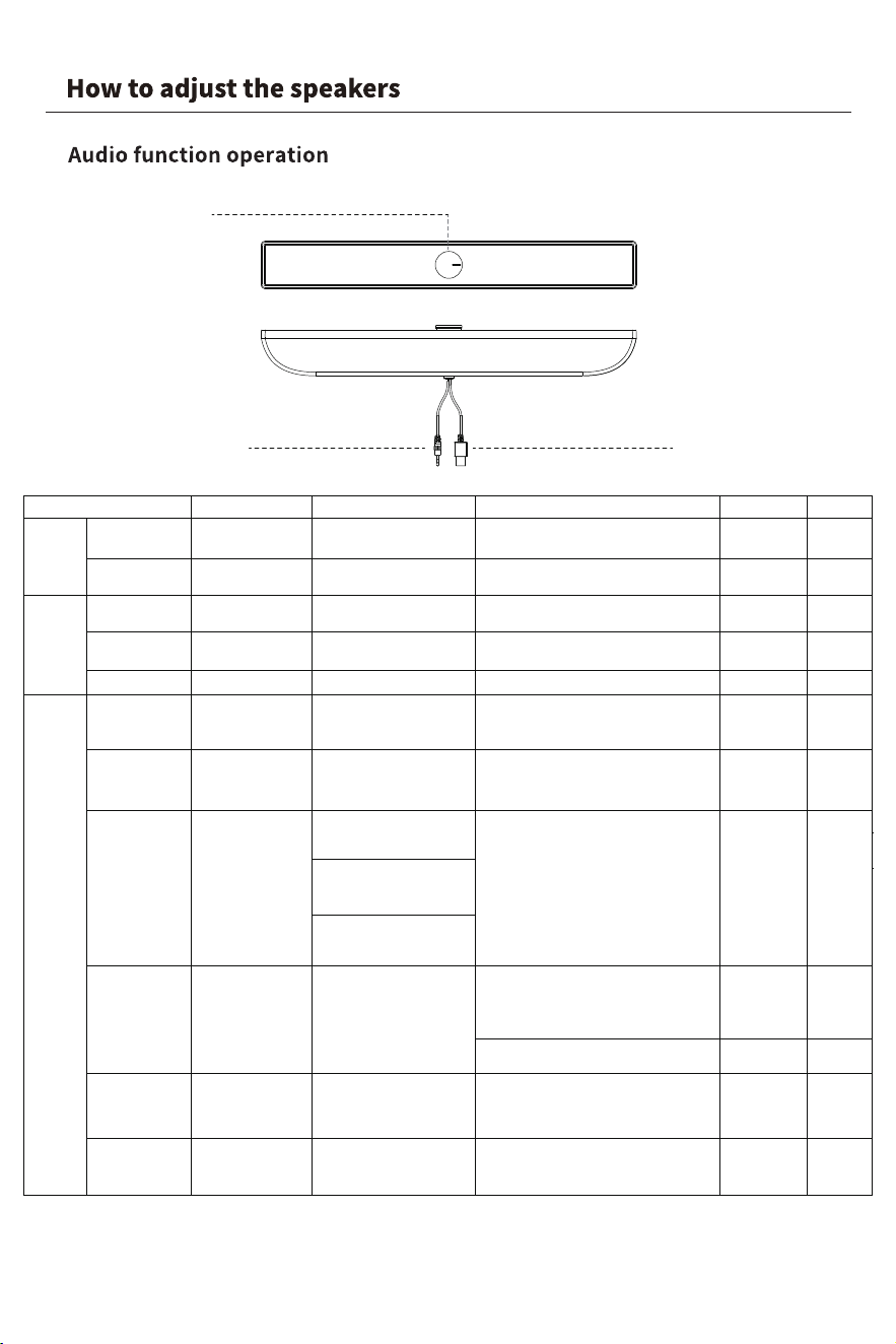
Default AUX audio mode
Knob keys
AUX audio input cable
Note: When your phone is connected to the speaker via Bluetooth and connected
to wired screen projection, please switch the speaker to AUX mode.
USB power cable
Tone
LED
/
/
/
The tone of
Power off
Blue LED
on 2s
The tone of
power off
Blue LED
flash quickly
The tone of
successful
connection
Blue LED
always on
The tone of the
disconnected
Blue LED
flash quickly
The tone of the
connected
Blue LED
always on
The tone of the
connected
Blue LED
always on
Blue LED
flash quickly
Blue LED
flash quickly
/
/
/
/
The tone of
Power on
Blue LED
on 2s
Pre-Condition
Operation
Effect
/
/
Connected the
power/ audio wire
Short press the
rotary switch
Power On
Volume up
Turn the switch clockwise
The volume increases
gradually as your rotation
Volume down
Turn the switch anticlockwise
The volume decreases
gradually as your rotation
Mode switch
Power on
Short press the rotary switch
Switch AUX mode and Bluetooth mode
Pairing status
Power on
1. Enter pairing status
2.Power off if no connect
with device within 5 mins
Power on
Open the Bluetooth and
search on the device
Find Bluetooth pairing name
"Wireless Speaker" and connect it,
successfully connected with tone "du"
Close your device
Bluetooth function
Cancel the pairing
on the device
Disconnect the Bluetooth
connection on device
1. After disconnected, speaker enter the
pairing mode, Blue LED flash
2. Power off if no connect with
the device within 5mins
Reconnected successful with device
Reconnected
Bluetooth mode
(paired with
device before)
Switch to Bluetooth mode,
speaker try to reconnect
with the last device
1.Enter the pairing mode if can't
reconnected within 5mins
2.Power off if can't connect with
device in pairing mode
within 5mins
Factory reset (In
Bluetooth mode)
Power on
In Bluetooth mode,
triple-click the
rotary switch
Factory reset
1. Clear the pairing history
2. Enter AUX mode
Power On
gTestin
Item
Sleep and
wake
Control
Bluetooth
function
Disconnected
Reconnected-
back to BT range
Connected
Disconnected
1. Connected with device,
the Bluetooth disconnected
after move the device out
of the BT range
2. It successfully reconnected if
back in BT range within 5mins
1. The tone"Disconnected"
2. Speaker enter the pairing mode
Power ffO
Connected the
power/
audio wire
Press and hold the
rotary switch by 3s
Power off
The tone of the
factory reset
function
Switch to pairing
mode (Bluetooth is
now discoverable
by other devices)
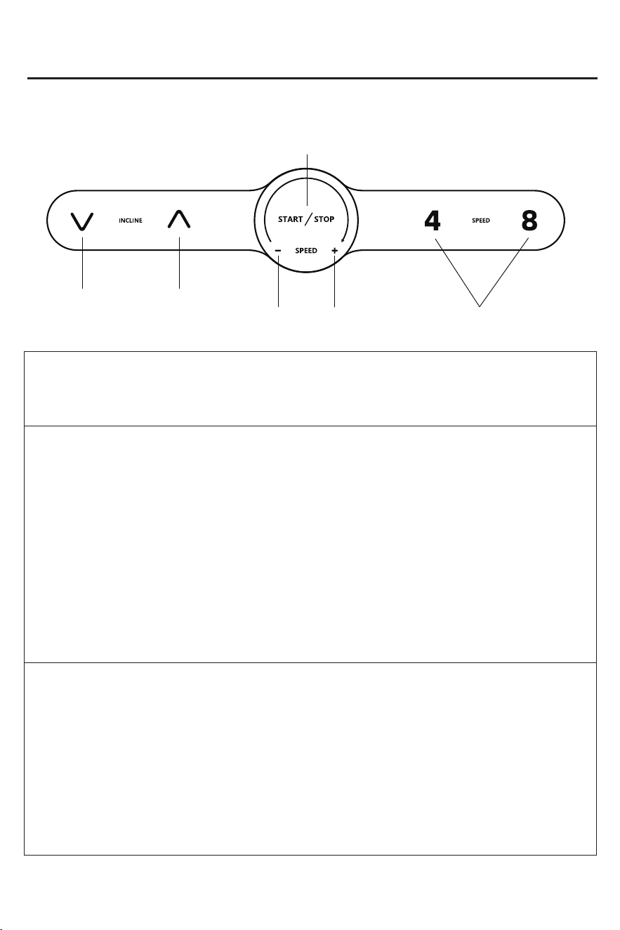
Panel function operation
1. Parameter Description
Exercise parameters for various exercise modes:
·The minimum display speed is 1kph/0.62mph.
·The maximum display speed is 14kph/8.7mph.
2. Panel Button Functions and Operation Instructions
Knob --- Function Description: Speed increase/decrease, Start/Pause/Stop key.
Operation Instructions:
·In standby mode, press the knob to start the treadmill.
·In operation mode, rotate the knob to adjust the speed.
·In operation mode, press the knob to pause the treadmill operation.
·In operation mode, hold down the knob to stop the treadmill operation.
Speed Shortcut Keys④,⑧ --- Function Description: Quick speed adjustment.
Operation Instructions:
·In operation mode, press the speed shortcut key to adjust to the corresponding speed.
Incline Adjustment Key --- Function Description:Controls the incline angle of the running deck.
Operating Instructions:
·Each time you press the up key, the slope increases by 1%.
If you press it for a long time, the slope continues to increase.
·Each time you press the down key, the slope decreases by 1%.
If you press it for a long time, the slope continues to decrease.
Instructions For Use
Speed-
Speed+
Up
Down
Speed shortcut key
mph
Start/Stop
3. Exercise Mode Description
Manual Mode Function Description
Entering Manual Mode: After the treadmill powers on and all displays light up, it enters full
manual operation mode. At this point, press the knob to enter manual operation mode.
Operation Instructions:
·The initial working speed is 1kph/0.62mph, and the time, distance, and calorie windows
start counting from zero.
·Rotate the knob to adjust the working speed.
·Press the speed shortcut keys④,⑧ to quickly adjust to the corresponding speed. press the knob to pause
the treadmill operation. (hold down the knob to stop the treadmill operation).
·Pulling out the safety lock can immediately stop the motor.
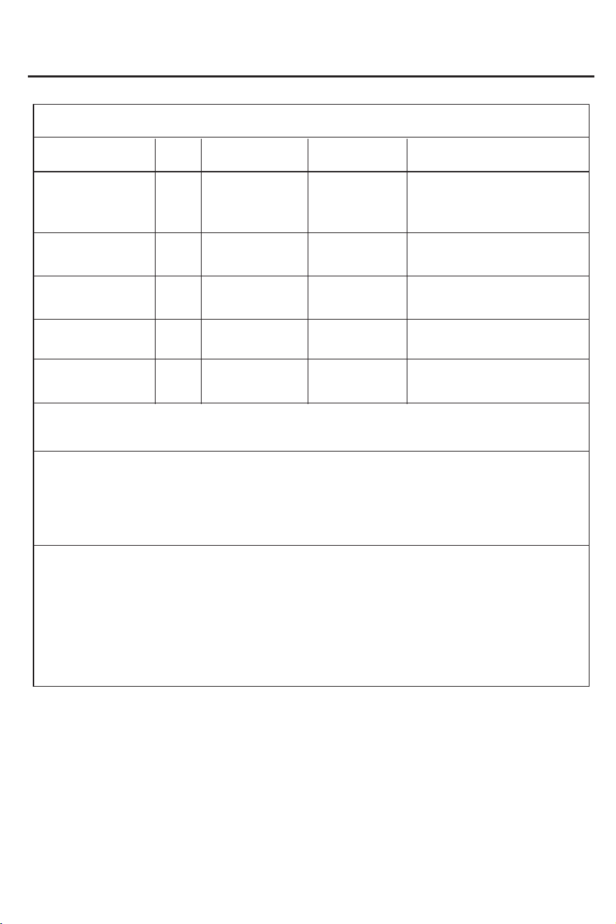
4.Display Range of Each Value:
Set parameters
Initial Set initial value Set range Display range
Time
(hours: minutes:
seconds)
0:00
0.0
1( k p h )/
0.62(mph)
1-14(kph)/
0.62-8.7(mph)
1-14(kph)/
0.62-8.7(mph)
0.00-9999(km)/
0.00-9999(mile)
0.0-9999
0.00
_
_
_
_ _
_
_
0.0
Speed
(kph)/(mph)
Distance
(km)/(mile)
Calories (kcal)
0-10% 0-10%
0
Incline (%)
Instructions For Use
5. Sleep Function Description:
When the treadmill stops working and no operation is performed for more than 10 minutes,
it will enter sleep mode. The display on the electronic monitor will automatically turn off.
Press any key to wake up the monitor, and after all displays light up, it will return to the
initial standby state.
6. Display Range of Each Value:
·During normal use, the safety lock must be inserted into the designated position on the
electronic monitor in order to operate it.
·Remove the safety key,a warning sound will be emitted.
·If the safety lock is removed during operation, the system will quickly stop, and after
reinserting the safety lock, all exercise data will be reset to zero.
00:00:00‒18:15:12
(hours: minutes: seconds)
Note: Due to equipment manufacturing deviations exist, the above data may
differ slightly from actual values and are for reference only.
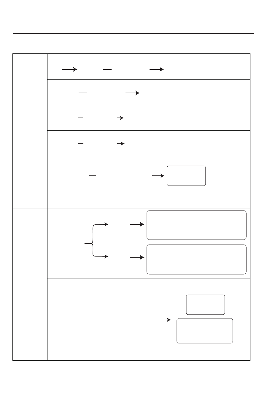
The buzzer sounds three times
Speed set to the lowest speed
The buzzer sounds three times
Speed set to the lowest speed
Enter
Short press the
knob
Short press the
knob
Standby
mode
Instructions For Use
Control Panel Operation
Start
Speed
adjustment
Pause state
Exercise state
Exercise state
In pause/stop state
Incline
Adjustment
Stop/Screen-off mode
Press the Up/Down key
Invalid
Invalid
Each level increases by 1%,
up to a total of 10%.
Resets to 0° after stopping
or screen timeout.
Workout/Pause/
In standby mode
Press the
up key
Press the
down key
The incline angle decreases. Each press lowers
the incline by 1%. Press and hold the button to
continuously decrease the incline. The incline
icon lights up, and the single-digit display shows
the incline level.
The incline angle increases. Each press raises
the incline by 1%. Press and hold the button to
continuously increase the incline. The incline
icon lights up, and the single-digit display shows
the incline level.
Left/right adjustment knob
Rotate the knob
to the right
Rotate the knob
to the left
Each press decreases the speed by 0.1 kph/mph;
During continuous knob rotation for ≥2 seconds, a "beep" prompt
sounds for each detent position rotation and each speed change .
With each detent rotation, the speed increases by 0.1 kph/mph;
With each detent rotation, the speed decreases by 0.1 kph/mph.
During continuous rotation for 2 seconds or more,each detent rotation
and each speed change will trigger a “beep” prompt tone.
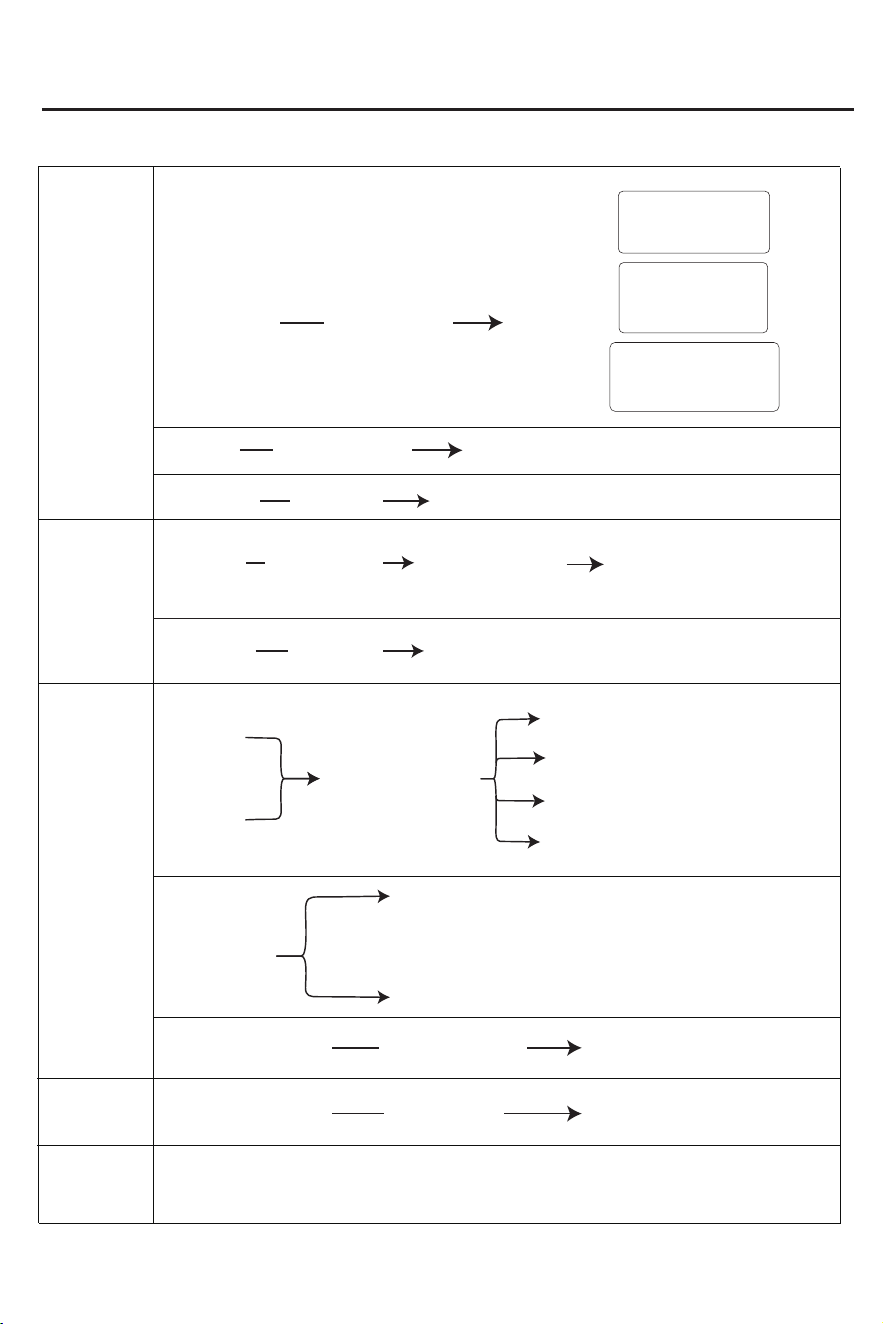
Instructions For Use
Pause
Pause
During workout
The display screen turns off
after 10 minutes of inactivity
No operation
Stop/Pause/End state
Reset data
End current workout
Secure the safety clip
The display will turn off after 10 minutes of inactivity
Paused state
no operation
The speed interface
displays 0
The distance interface
displays the paused
workout mileage
Time/calories Interface
displays the time/calories
before the pause
End
workout
The display will turn off after 10 minutes of inactivity
Stop state
No operation
End workout
The speed decreases
by 0.5 kph per second
until it reaches 0
Workout data: Except for the speed,
which shows 00, other values display
the data before the workout ended
Stop state
Press and hold the
knob for 3 seconds
In motion
Non-exercise
Unfasten the safety latch
The buzzer will beep
continuously until the
safety lock is installed
No response to button press
Secure the safety
latch in place
Error code disappears
The display shows error code E98
Workout data: Except for the speed,
which shows "00," other values display
the data before the emergency stop
The buttons are functioning normally
Workout
automatically
stops
Stop
Screen off
Shuts down automatically after >90 minutes of inactivity, resets timer when operated.
Short press the
knob
End workout
Paused
Press and hold the
knob for 3 seconds
APP Usage Instructions
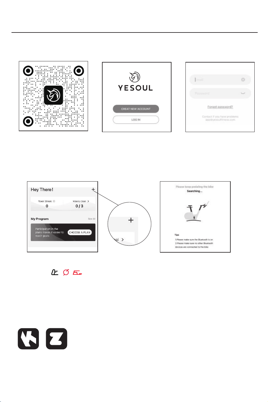
Connect devices
·When using for the first time, click the 「+」 in the upper right corner of the「Home」
or enter the course and connect the device according to the interface prompts.
APP installation registration
·You can scan the QR code below to download the APP and register an APP account.
·Turn on the ( / ) button for the sports mode or course in the APP to establish
connection automatically.
·The device does not support connecting multiple cell phones at the same time.
Please confirm that no other users are connected to the device at this time before use.
·After shutting down, Bluetooth will be automatically disconnected.
·In addition to connecting with YESOUL FITNESS APP, Bluetooth can also be connected
with Kinomap and Zwift software.
·The display will automatically go into sleep mode 10 minutes after the exercise ends.
Zwift
Kinomap
2. Enter the APP login page
1.Scan the QR code and
download the APP
4. Enter the APP homepage
3. Register an APP account
5.Search for devices
Purchase APP membership
Open the APP and find 「Homepage」-「Settings」- 「Member Rights」,
and follow the interface prompts to complete the membership purchase.
APP Usage Instructions
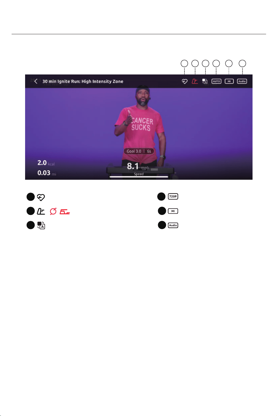
About unit switching
1 2 3 4 5 6
Bluetooth Heart Rate Monitor Connection
2
1
Bluetooth Device Connection
3
Subtitles / Voice Translation
4
Metric / Imperial Units Toggle
6
Video Resolution
5
Audio Controls
/
( )
· The "Bluetooth Device Connection" icon may vary depending on the type of device
supported by each course. Please follow the on-screen instructions to connect the
appropriate device.
· The above illustrations are for reference only. Since the software is constantly
updated and iterated, please refer to actual use.
·Due to variations in terminal device configurations, certain features may not function
properly. Please select a compatible device based on your actual situation.
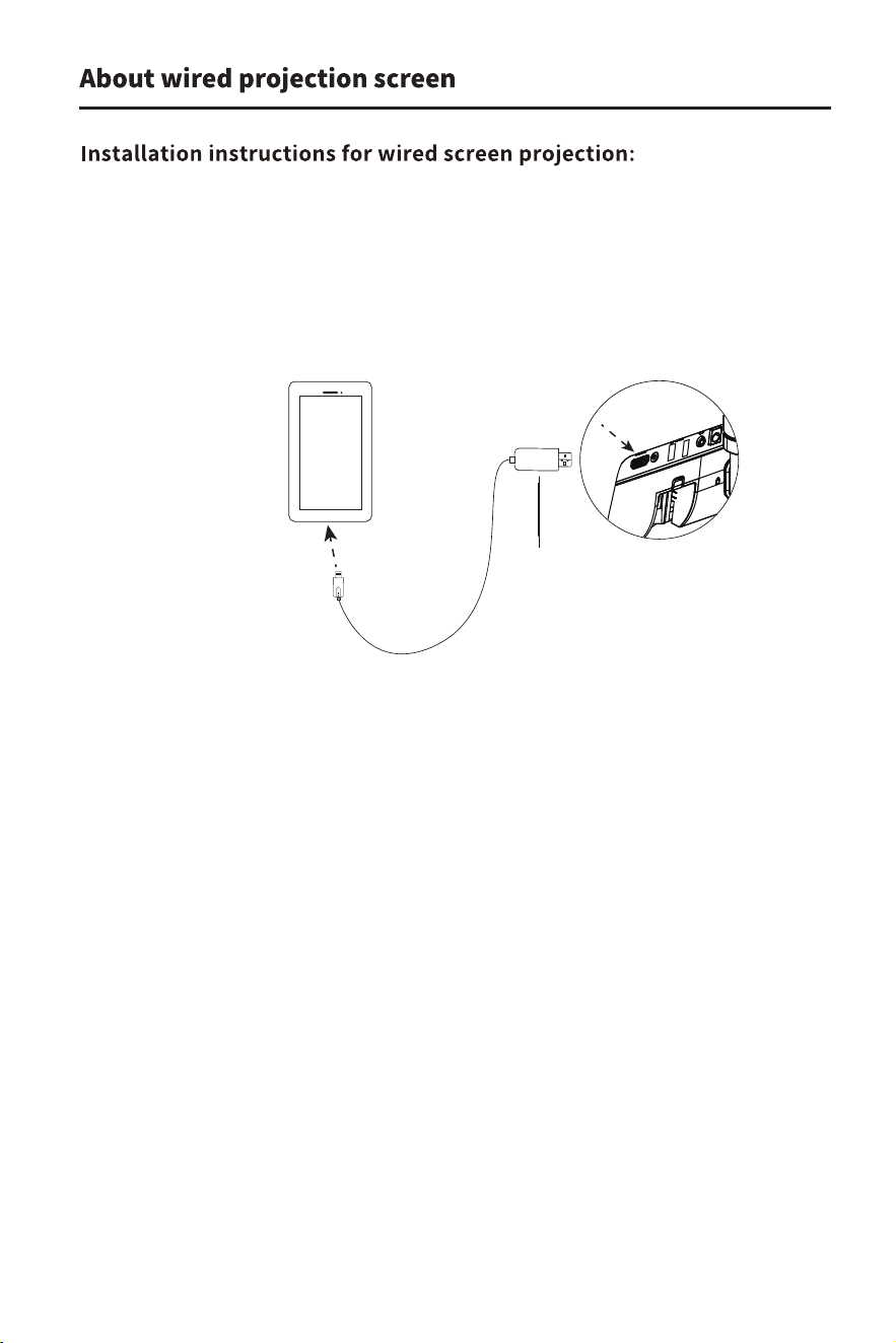
Wire outlet
Screen mirroring adapter
Mobile devices:
1. Download the Yesoul Fitness app and register.
2. Connect your device within the app.
3. Connect your phone with a screen casting cable.
(Phone must support DisplayPort).
Note: There are two screen mirroring adapters for Android and IOS in the
package.Please use them according to the model of your phone.
Walking
wheel
Instructions For Use of the Machine
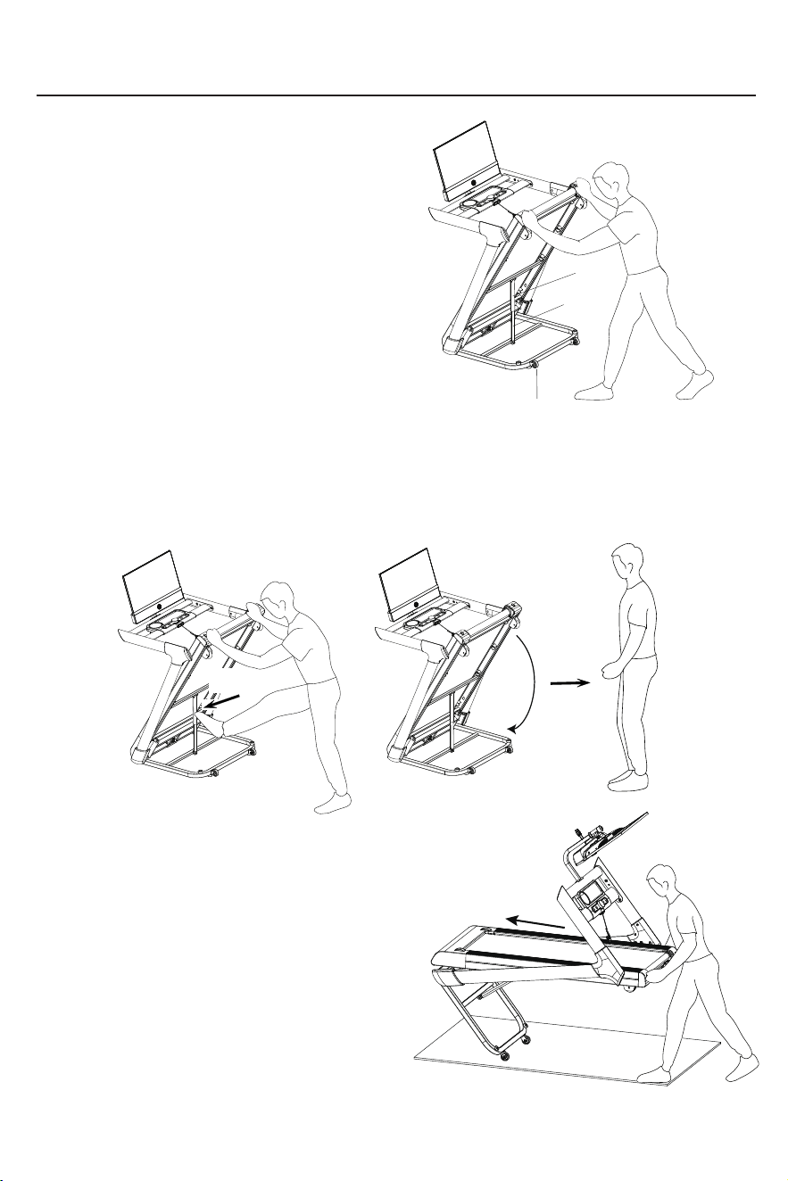
Folding and moving the treadmill
·Folding of treadmill
1. Before folding the treadmill, ensure the
power is disconnected.
2. Check whether the incline of the treadmill
is at the lowest position.
3. Lift the treadmill to the upright position,
and the non-return pipe will automatically
get stuck on the pneumatic cylinder.
4. Verify that the anti-return tube is properly
engaged with the pneumatic cylinder.
· Deployment of treadmill
1. To unfold the treadmill, you need to choose a place
about 1 meter away from the power socket and with a
flat ground and no other obstacles.
2. When unfolding the treadmill, you must first hold the
treadmill with both hands and step on the anti-return
tube with your feet. The treadmill will automatically
lower to the ground slowly. At this time, the person
must stay about 1 meter away from the treadmill
until the treadmill is fully unfolded.
When moving the unit you must make sure:
1: The treadmill power switch is turned off.
2: The power plug has been pulled out from the
power socket.
3: The large frame has been folded. After clarifying the
above points, grab the end of the treadmill with one
hand and the handrail on the same side with the other
hand. When tilting 40 to 50 degrees toward your chest,
you can slowly move the machine.
·Movement of treadmill
Please stay
away from
Kick towards
the arrow
Check
tube
Pneumatic
cylinde
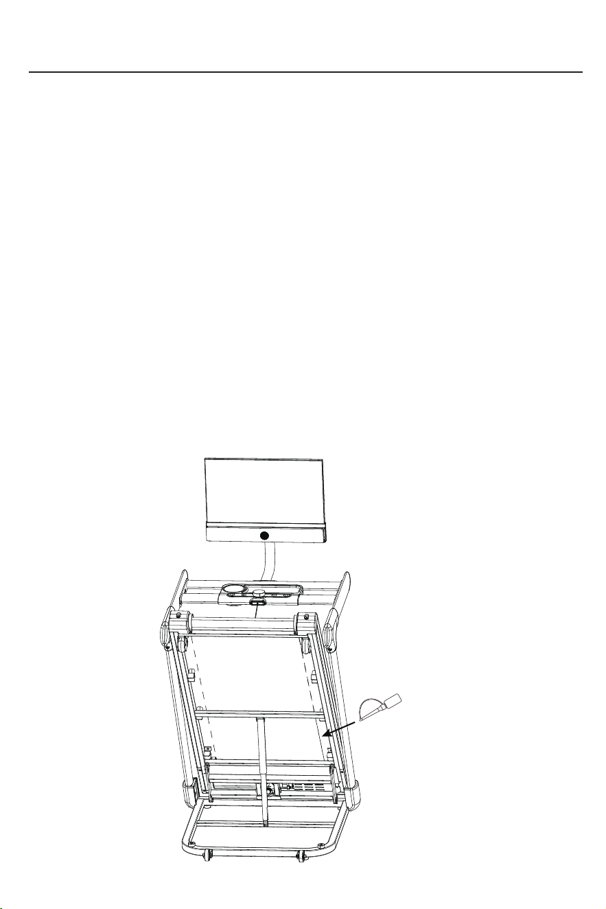
Lift the running belt
Routine Maintenance
·Lubrication
After the running belt has been used for a period of time, it must be lubricated with
specially formulated methyl silicone oil.
Recommendation: Use less than 3 hours per week Lubricate once every 5 months
Use 4~7 hours per week Lubricate once every 2 months
Use more than 7 hours per week Lubricate once a month
Note: Do not over-lubricate. More lubricant is not always better. Proper lubrication
is an important factor in extending the service life of the treadmill.
·How to judge whether lubricant needs to be applied again
Just grab the running belt and touch your hand as far as possible to the center of the
back of the running belt. If there is silicone on your hand (it feels a little moist), it means
no more lubricant is needed. If the running board is dry , and there is no silicone stuck to
your hands, you need to add lubricant.
·Steps to apply lubricant to running boards
Stop the running belt, fold the machine, lift up the running belt on the back of the main
frame, put the oil bottle into the middle of the running belt as much as possible, spray
silicone oil on the inside of the running belt, and coat both sides of the running belt with
silicone. Run the treadmill at a speed of 1kph/0.62mph to evenly apply the silicone,
and gently step on the running belt from left to right. It will take a few minutes for the
silicone to be completely absorbed by the running belt. (as the picture shows)
Routine Maintenance
·Tightness adjustment of running belt
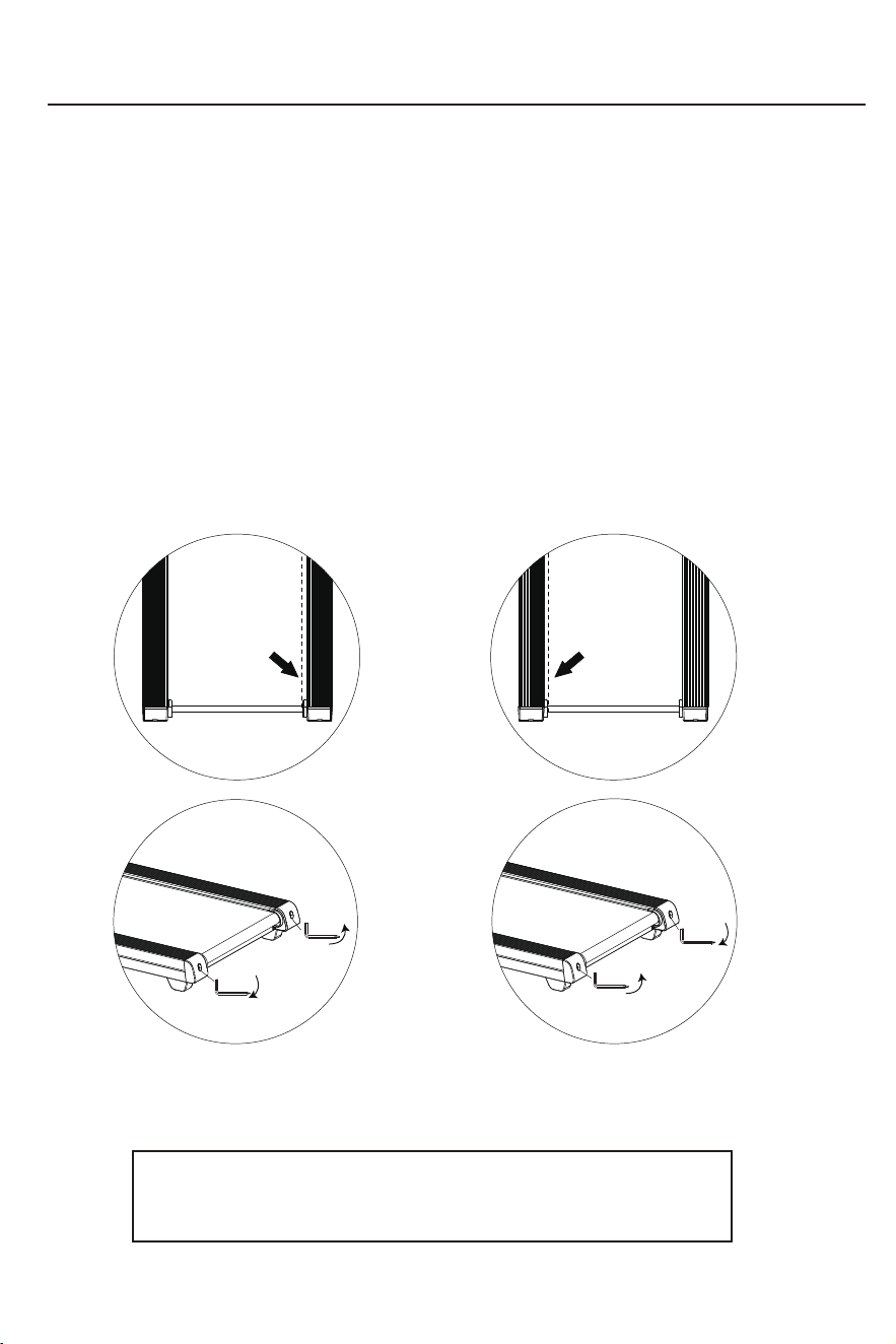
The user has a tendency to stop and slip while running. When this phenomenon occurs, adjust
the running belt adjustment bolts left and right simultaneously in half-turn clockwise directions.
If the running belt is too loose, the running belt and rollers will slip when you step on the belt.
However, it is not good if it is too tight. It will easily increase the load on the motor and damage
the motor, running belt and rollers.
·Adjustment of running belt deviation
All treadmills require adjustment of the running belt before leaving the factory and after
installation. However, after a period of use, it may still wander. The reasons for this
phenomenon are as follows:
① The host is not placed smoothly
② The user’s feet are not in the center of the running belt when exercising
③ The user exerts uneven force on both feet
If the misalignment is artificially caused, it can return to normal after a few minutes of no-load
rotation. For misalignment that cannot be restored automatically, use the L-type hexagon
wrench 6# (A) that comes with the machine to gradually adjust it in half-turn increments.
Declare:
Deviation of the running belt is mainly maintained by the user according
to the instructions. Deviation of the running belt will seriously damage
the running belt, so it must be discovered and corrected in time.
If the running belt deviates to the left,
adjust the left bolt clockwise or the
right bolt counterclockwise.
If the running belt deviates to the right,
adjust the right bolt clockwise or the
left bolt counterclockwise.
(Tight)
(Tight)
Turn clockwise to
increase running
belt tension
(Loose)
(Loose)
Turn clockwise to
reduce walking
belt tension
The running belt is
deviating to the left
The running belt is
deviating to the right
Common Faults and Solutions
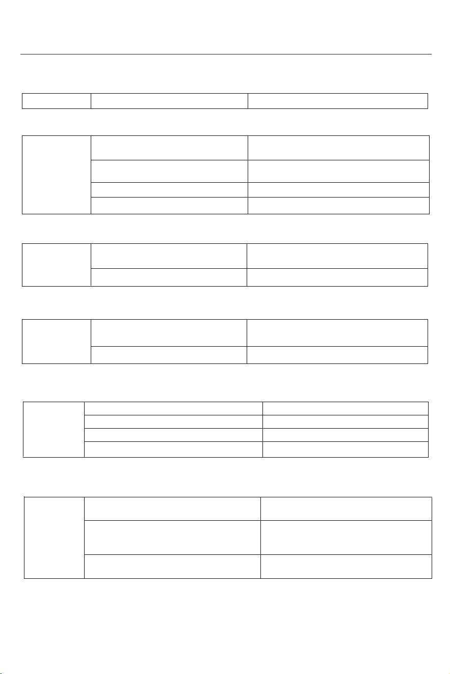
Treadmill brushless system error message prompts:
Er02: indicates the lower control power input overvoltage protection information prompt
Er01: indicates abnormal communication between the electronic meter and the electronic control
Er03: indicates the input undervoltage protection information of the lower control power supply
Er04: Indicates that the main motor is open circuit, phenomenon prompt
Er05: indicates that the current ADC is abnormal
Fault codes Fault code meaning Fault code processing method
Er01
Er02
Er03
Er04
Er05
The upper and lower control main
connection line interface is loose
The upper and lower control main
connection line is broken
The electronic meter is broken
The controller is damaged
Reinforce the connection line interface
Replace the upper and lower control main
connection line
Replace the electronic meter
Replace the controller
An external filter regulator needs to be added
Replace the lower control, waiting for repair
The user's grid voltage is unstable,
and the peak voltage is too high
An external filter regulator needs to be added
Replace the lower control, waiting for repair
The user's grid voltage is unstable,
and the peak voltage is low
The main motor line is not connected or loose
The load of the treadmill exceeds the
rated working current of the motor
There is a problem with the assembly
structure of the treadmill and the motor,
causing resistance or blockage of the motor
Failure of the lower control current
limiting system
It is recommended to be within the rated
working current range of the motor
Check whether the treadmill structure
is normal
Replace the lower control, waiting for repair
The main motor is open circuit, damaged
The controller is open circuit, damaged
The main motor is blocked and damaged
Reinforce the main motor connection line
Replace the motor
Replace the controller
Replace the motor
The controller is damaged
The controller is damaged
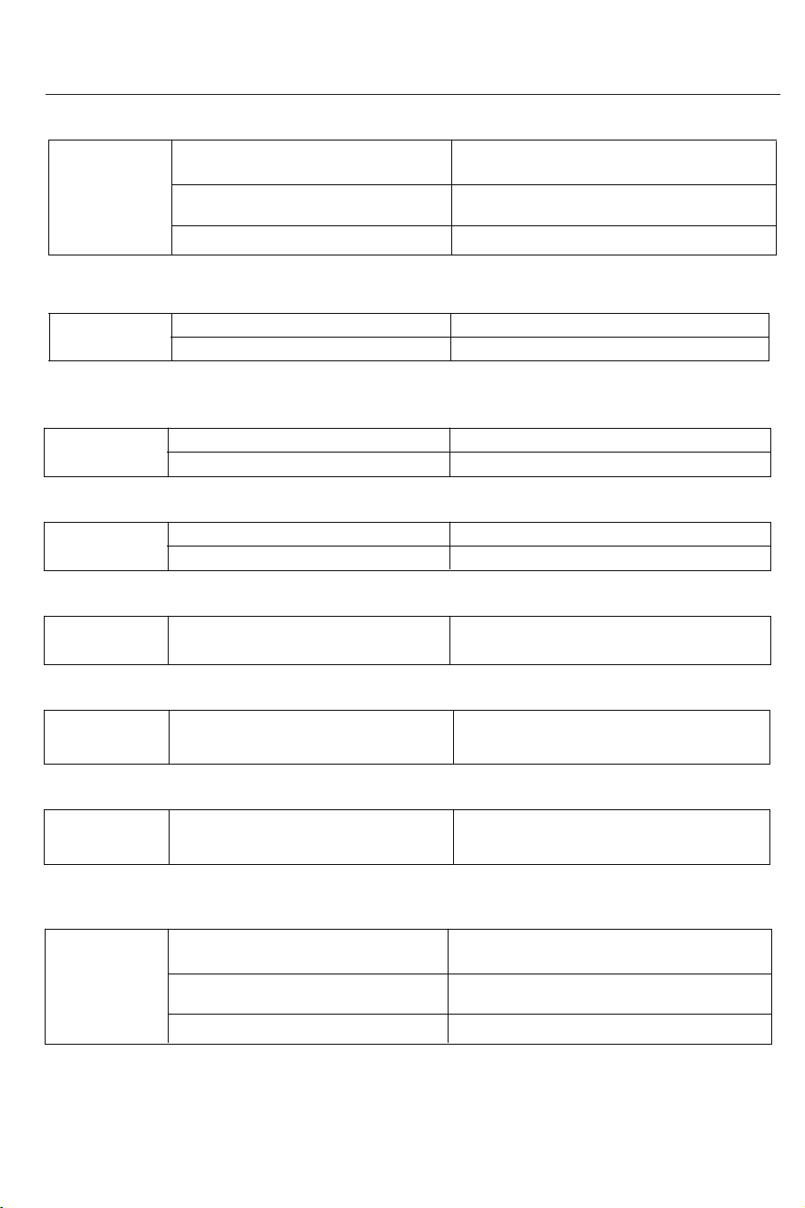
Elevation motor connection wire fault
Elevator fault
Calibration error
Check connection wires (total of 4 wires)
Replace the elevator
Recalibrate
Er18
Er18:Indicates a fault warning during the elevation calibration process
Common faults and Solutions
Er06: indicates voltage ADC abnormality prompt
Er08: indicates that the 3s three-phase current deviation is greater than the set value
Er11: indicates that the maximum current exceeds the setting
Er13: indicates abnormal Hall signal value or timing error
Er14: Controller temperature is too high
Er15: indicates power tube breakdown explosion protection information prompt
Er17: Indicates that the Hall signal error is too large
The user's grid voltage is unstable,
and the peak voltage is too high
Main motor damaged
Controller abnormally damaged
Replace motor
Replace controller
Wrong wheel diameter value setting
Controller damage
Need to add an external filter stabilizer
Reset the wheel diameter value and try not
to exceed the rated voltage of the motor
Replace the lower control, waiting for repair
Er08
Er06
Er11
Er13
Er14
Er15
Er17
Main motor damaged
Controller abnormally damaged
Replace motor
Replace controller
Replace controller
Replace controller
Main motor damaged
Controller abnormally damaged
Controller abnormally damaged
Replace motor
Controller temperature is too high Stop using for more than 1 hour
The power transistor breaks down and
the controller is damaged
Replace controller
NOTE: Perform the operations above only during power disconnection.
If the fault code persists, contact the after-sales service team for assistance.
Common faults and Solutions
Elevation motor connection wire fault
Elevator fault
Calibration error
Check connection wires (total of 4 wires)
Replace the elevator
Recalibrate
Er19
Er19: Indicates a fault warning for the elevation motor
Er98: Indicates a safety key not properly inserted
1. This product must be grounded. If the treadmill malfunctions or becomes damaged,
the grounding wire creates a circuit of lowest resistance and conducts current under-
ground, reducing the risk of electric shock. This product comes with a cable that has a
conductor and a grounding plug that ground the equipment.
2. The plug must be inserted into an outlet that meets local codes and ordinances installa-
tion and grounding requirements.
3. Improper connection of the equipment grounding conductor may result in electric shock
hazards. If you are unsure whether your equipment is properly grounded, consult a
qualified electrician or service personnel. Please do not modify the plug provided with this
product without authorization. If the plug
If inconsistent with the outlet, have a qualified electrician install a proper outlet.
Grounding Guide
Er98
Er99:Indicates lower control information lost warning
Er99
Safety key disconnected Check the wiring
Connection not secured Check the wiring
Warm up
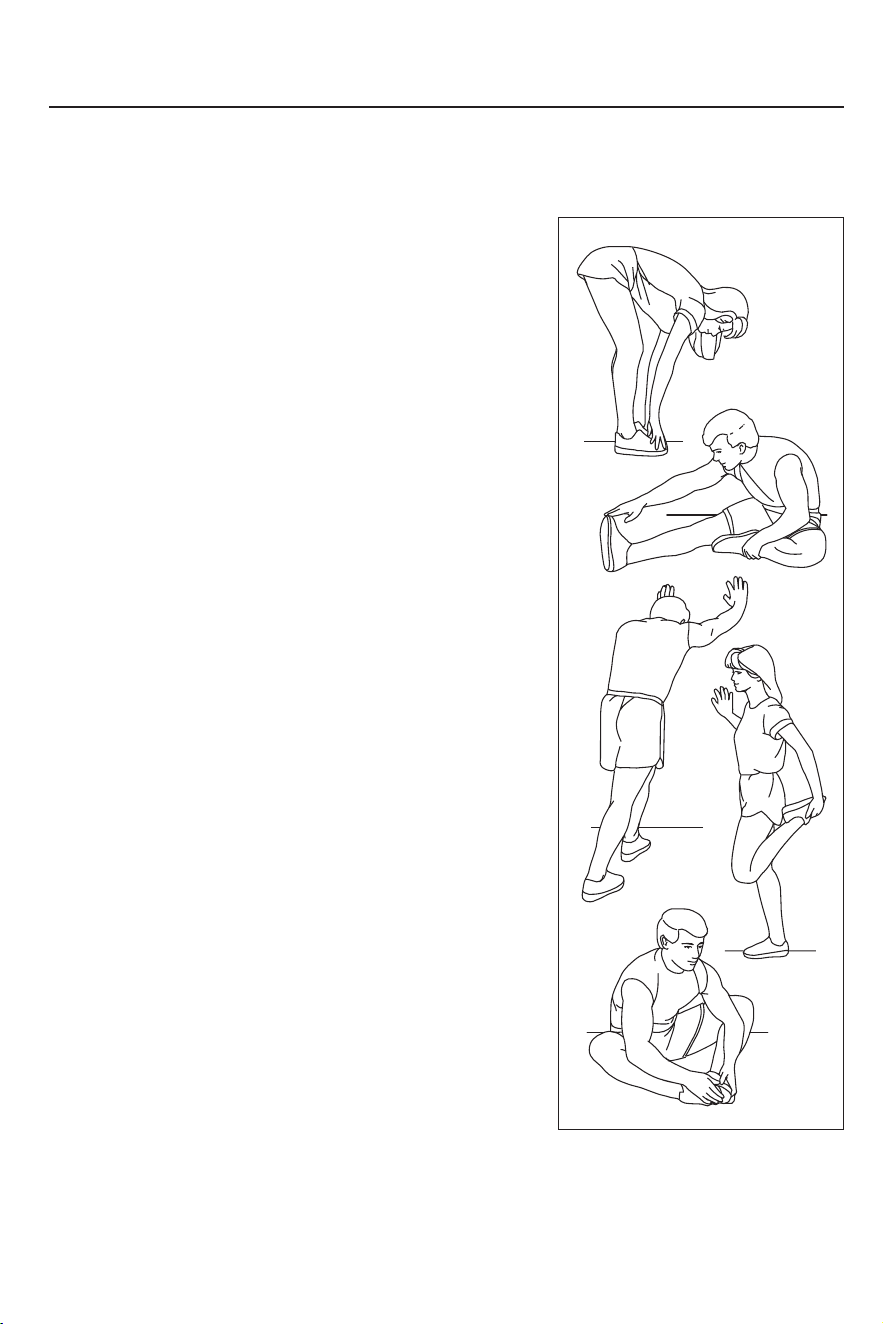
Before exercising, it is best to do stretching exercises.
Warm muscles stretch more easily, so warm up for 5
to 10 minutes first. Then stop and stretch as follows -
5 times for 10 seconds or more on each leg, then do it
again at the end of the exercise.
1.Stretching by touching toes
Stand with your knees slightly bent and your hips moving
slowly forward. Touch yourtoes as far as possible, while
relaxing your back and shoulders. Keep this posture for 15s
and thenrelax. Repeat the exercise three times.
Stretched parts: Ligaments,internal parts of knees, and back.
(See Figure 1)
2.Ligament stretching exercise
Sit with one leg stretched forward.Put the other sole close
to your body andon the inner side of the thigh of the stretched
leg. Touch your toes as far as possible. Keep thisposture for 15s
and then relax. Exercise both legs three times, respectively.
Stretched parts:Ligaments, back and groin.(See Figure 2)
Stand with one hand against the wall for balance and the other
hand reaching back to grab your foot. Pull your heel as close to
your buttocks as possible. Keep this posture for 15s and
then relax. Repeat the exercise three times for each leg.
Stretched parts: Quadriceps and hip muscles. (See Figure 3)
3.Calf/heel stretching exercise
Stand with one hand against the wall for balance and the other
hand reaching back to grab your foot. Pull your heel as close to
your buttocks as possible. Keep this posture for 15 seconds and
then relax. Repeat the exercise three times for each leg.
Stretched parts: Quadriceps and hip muscles. (See Figure 4)
4.Quadriceps femoris stretching exercise
Sit with the soles of your feet together and your knees turned out.
Make your feet asclose as possible to the groin. Keep this posture
for 15s and then relax. Repeat the exercise threetimes.
Stretched parts: Ouadriceps and hip muscles. (See Figure 5)
5.Inner thigh stretching exercise
Note: This product is a full-body training equipment,
please follow the above steps to perform warm-up exercises.
1
2
3
4
5

This device complies with Part 15 of the FCC Rules
Operation is subject to the following two conditions:
(1) this device may not cause harmful interference, and
(2) this device must accept any interference received, including interference that may cause
undesired operation.
This device has been tested and found to comply with the limits for a Class B digital device,
pursuant to Part 15 of the FCC Rules. These limits are designed to provide reasonable
protection against harmful interference in a residential installation. This device generates,
uses and can radiate radio frequency energy and, if not installed and used in accordance
with the instructions, may cause harmful interference to radio communications.
However, there is no guarantee that interference will not occur in a particular installation.
If this device does cause harmful interference to radio or television reception, which can be
determined by turning the device off and on, the user is encouraged to try to correct the
interference by one or more of the following measures:
--Reorient or relocate the receiving antenna.
--Increase the separation between the device and receiver.
--Connect the device into an outlet on a circuit different from that to which the receiver is
connected.
--Consult the dealer or an experienced radio/TV technician for help.
Changes or modifications not expressly approved by the party responsible for compliance
could void the user's authority to operate the equipment.
The device has been evaluated to meet general RF exposure requirement. The device can
be used in portable exposure condition without restriction.