HTTP : http://www.micradar.cn/
The final interpretation of this product belongs to Yunfan Ruida Technology ( Shenzhen ) Co.,
Ltd. Any changes will not be notified separately.
Produce Taste Specifications
Product Specification V1.6
Product Model: R24AVD3-FIH
Product Name: 24G Personnel detection radar
Product Description: 24G, human body detection, high
sensitivity

HTTP : http://www.micradar.cn/
The final interpretation of this product belongs to Yunfan Ruida Technology ( Shenzhen ) Co.,
Ltd. Any changes will not be notified separately.
I. Product Features
This radar is a high-sensitivity radar. 24GHz
Millimeter-wave radar module for human body detection and
location detection .
This radar module has the following features:
1) based on FMCW The radar system enables the detection of the presence
of people within the area .
2) To achieve synchronous sensing of both moving and stationary
individuals;
3) Maximum motion sensing distance: ATARI models≤2 meters , Nintendo
models ≤4 meters ;
4) Maximum static human body sensing distance: ATARI models≤ 2 Meters
, Nintendo models ≤ 4 meters ;
5) Adaptable to meeting screen scenarios, with no one making a judgment
within 15 seconds;
6) Antenna beamwidth (3dB ):≤ 100° (H );≤ 80° (E );
7 ) It has scene recognition capabilities, identifying whether there
are people or no people and the status of people's activities;
8 ) Unaffected by temperature, humidity, noise, airflow, dust, or
light, it is suitable for harsh environments;
9 ) It has low output power and will not cause harm to the human body
even after prolonged exposure.
HTTP : http://www.micradar.cn/
The final interpretation of this product belongs to Yunfan Ruida Technology ( Shenzhen ) Co.,
Ltd. Any changes will not be notified separately.
II. Scope of Application
Conference screen scenario
Home appliances
Office energy saving
Automatic doors, elevators, etc.
III. Main Functions and Performance
Parameters
1: Functional Requirements
1) Presence detection of personnel;
2) GPIO high and low level output (person - high level / no person -
low level);
3) Other radar functions ;
a. OTA
b. Self-test and fault diagnosis
2 :Electrical parameters
parameter
Minimum
value
Typical
value
Maximum
value
unit
Radar operating parameters
Operating voltage (VCC)
4.5
5
5.5
V
Operating current (I
CC
)
80
100
1 20
mA
Operating
temperature(T
OP
)
-20
+70
℃
Storage temperature (
TST
)
-40
+85
℃
launch parameters
Operating frequency ( F
TX
)
24.0 5
24.25
GHz
Transmit power (P
out
)
6
8
dBm
Antenna parameters

HTTP : http://www.micradar.cn/
The final interpretation of this product belongs to Yunfan Ruida Technology ( Shenzhen ) Co.,
Ltd. Any changes will not be notified separately.
3. Radar detection performance parameters
1) Motion sensing distance: ATARI models≤ 2 meters (radial) , Nintendo
models ≤ 4 meters ;
2) Stationary human perception distance: ATARI models ≤ 2 meters (radial)
, Nintendo models ≤ 4 meters ;
3) FOV (Field of View): ≤90 °;
4) Motion trigger time: ≤0.5s;
5) Presence detection time: ≤15s;
IV. Applications and Interfaces
1. Power Requirements
1) Input voltage: DC +5V±0.5V;
2) Operating current: Module current 100mA (Max ) , the power supply end
should have a margin of more than 3 times, approximately 300mA ;
3) Power supply ripple: ≤50mV;
2. Environmental Adaptability Description
1) Temperature: -20℃ to 70℃ (operating and storage)
2) Humidity: ≤85%, no condensation
3) Vibration: No vibration
3. Interface Description
3.1 Physical Interface Description
Antenna gain (
GANT
)
5
dBi
Horizontal beam (3dB)
100
°
Vertical beam (3dB)
80
°
HTTP : http://www.micradar.cn/
The final interpretation of this product belongs to Yunfan Ruida Technology ( Shenzhen ) Co.,
Ltd. Any changes will not be notified separately.
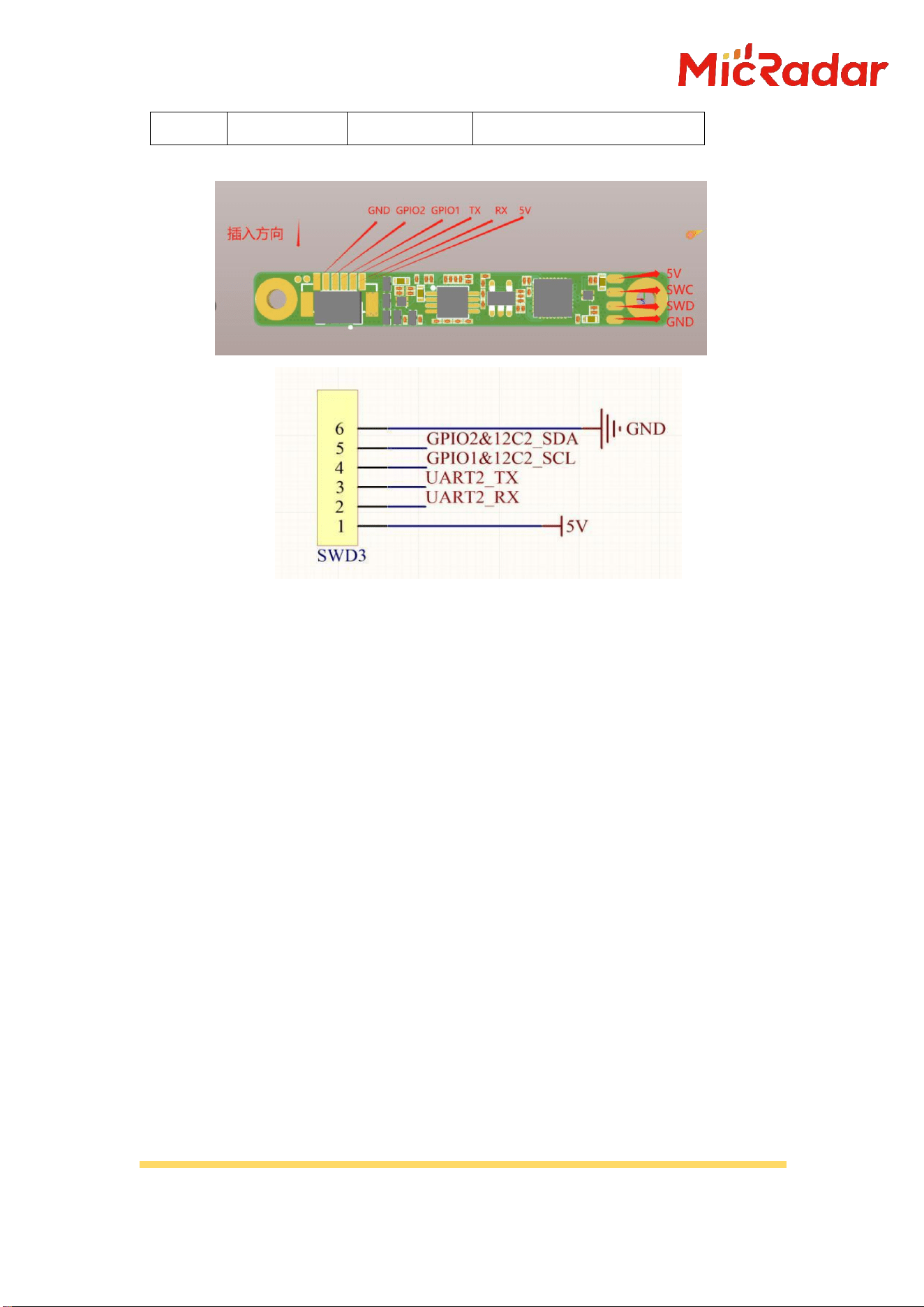
This radar provides a 6-pin interface, including one UART and one pair
of GPIOs. The GPIOs can be used as an IIC interface to replace the UART
as needed, using an FPC connector . ( FPC 0.5mm 6-pin horizontal mount
)
The interfaces are ordered as follows:
pin
describe
Typical
value
illustrate
1
5V
5.0V
Positive power input
terminal
2
RX
3.3V
Serial port reception
3
TX
3.3V
Serial port transmission
4
GPIO1
3.3V
High level when someone is
present / Low level when no
one is present
5
GPIO2
3.3V
High level when someone is
present / Low level when no
one is present
HTTP : http://www.micradar.cn/
The final interpretation of this product belongs to Yunfan Ruida Technology ( Shenzhen ) Co.,
Ltd. Any changes will not be notified separately.
6
GND
0V
land
Note: The default interface uses UART Serial port ; Current GPIO 1
and GPIO 2 The output is redefined according to user needs , and high
and low level outputs are provided for radar judgment status (high
level for manned/low level for unmanned status indication ) .
3.2 Interface Description
The radar-user interface mainly includes the following:
A. Radar information parameters ;
B. Radar detection data ;
C. Radar test and self-test information; D. OTA interaction, etc.
3.3 Firmware Version Rules
Nintendo model: SVD3.LJN.XX.XX.X X
ATAR model: SVD3.LJA.XX.XX.XX
SVD3 - Firmware Number
HTTP : http://www.micradar.cn/
The final interpretation of this product belongs to Yunfan Ruida Technology ( Shenzhen ) Co.,
Ltd. Any changes will not be notified separately.
LJN/LJA - Abbreviation for User Application
XX.XX.XX - Version number iteration (initial version was 00.00.01)
For example: SVD3.LJN-00.00.01
3.4 Interface Protocol Description
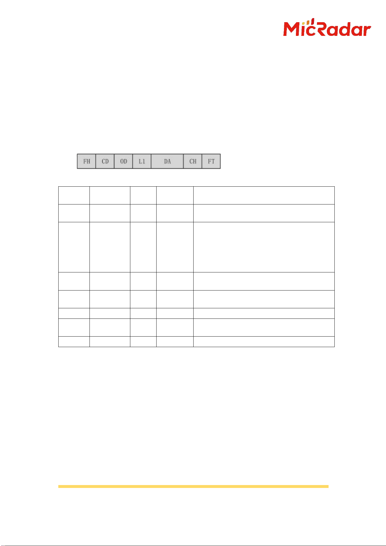
The frame format is defined as follows:
Serial
Number
Fields
mark
Length (B)
illustrate
1
Frame
header
FH
2
Fixed as "0x53 0x59" " //" S Y"
2
control
word
CD
1
0x00 - Heartbeat Packet
Identifier; 0x01 - Product
Information; 0x02- OTA Upgrade;
0x03 - Radar Test;
0x80 - Exclusive features;
3
command
word
OD
1
The current data content needs to be
identified; this is yet to be defined.
4
Length
indicator
L1
2
equal DA Data length
5
data
DA
-
0~2048 Byte
6
Validation
fields
CH
1
Checksum
7
Frame end
FT
2
Fixed as "0x54 0x43" " //" T C"
HTTP : http://www.micradar.cn/
The final interpretation of this product belongs to Yunfan Ruida Technology ( Shenzhen ) Co.,
Ltd. Any changes will not be notified separately.
Protocol address :
Protocol address
Function
Description
Transmission
direction
Frame
header
control
word
command
word
length
data
Validation
fields
Frame
end
Product Information
Initialization
complete
information
Actively
report
5359
05
01
0001
0F
SUM
5443
Initialization
completion
information
query
Issued
5359
05
81
0001
0F
SUM
5443
reply
5359
05
81
0001
01: Completed
02: Incomplete
SUM
5443
Firmware
version query
Issued
5359
02
A4
0001
0F
SUM
5443
reply
5359
02
A4
Len
Len Byte
firmware version
SUM
5443
Radar UID Query
Issued
5359
02
A0
0001
OF
SUM
5443
reply
5359
02
A0
Len
Len Byte (Unique
Number)
SUM
5443
Information exists in the human body
Human body
presence
information
reporting
Actively
report
5359
80
01
0001
0x00: No one
0x01: Someone
SUM
5443
Human body
information
query
Issued
5359
80
81
0001
0F
SUM
5443
reply
5359
80
81
0001
0x00: No one
0x01: Someone
SUM
5443
OTA
Start OTA
upgrade
Issued
5359
03
01
0004
4-byte firmware
package size
(For example:
firmware size is
150K (150*102)
When it is 4
bytes, the
content of 4
bytes is: 00 02
58 00
(big-endian).
Sum
5443
reply
5359
03
01
0004
4-byte upgrade
packet size per
frame
Sum
5443
Upgrade
package
transfer
Issued
5359
03
02
0404
4-byte packet
offset address +
1024-byte data
packet
Sum
5443
reply
5359
03
02
0001
01: Received
successfully
02: Reception
failed
Sum
5443
End OTA upgrade
Issued
5359
03
03
0001
01: Firmware
package sent
successfully
02: Firmware
package delivery
incomplete
Sum
5443
HTTP : http://www.micradar.cn/
The final interpretation of this product belongs to Yunfan Ruida Technology ( Shenzhen ) Co.,
Ltd. Any changes will not be notified separately.
reply
5359
03
03
0001
01: Received
successfully
02: Reception
failed
Sum
5443
Production energy value
Production
measurement
energy value
output
Issued
5359
08
8A
0001
0F
Sum
5443
reply
5359
08
8A
0005
4B Energy Value
1B Distance
Value
Sum
5443
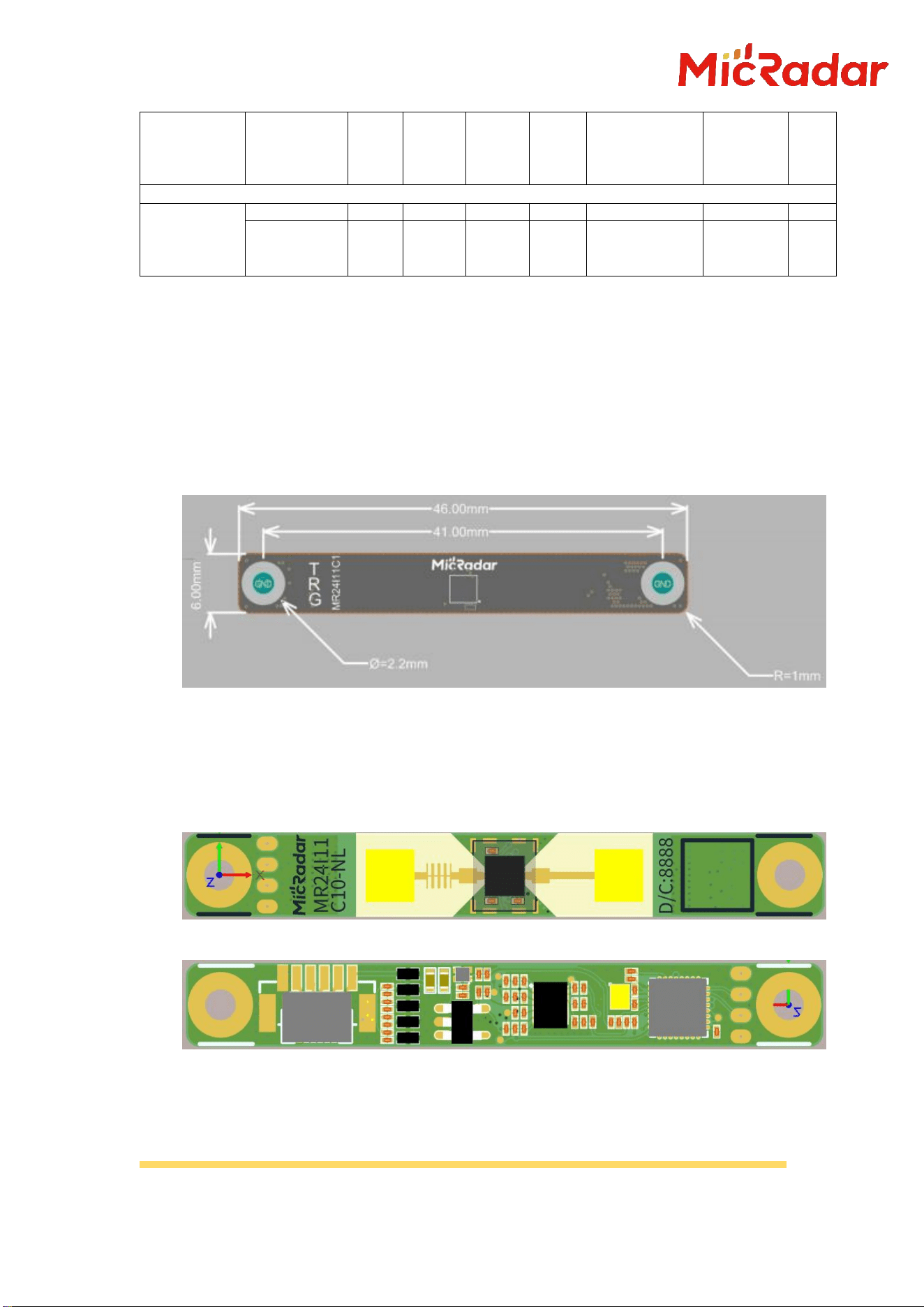
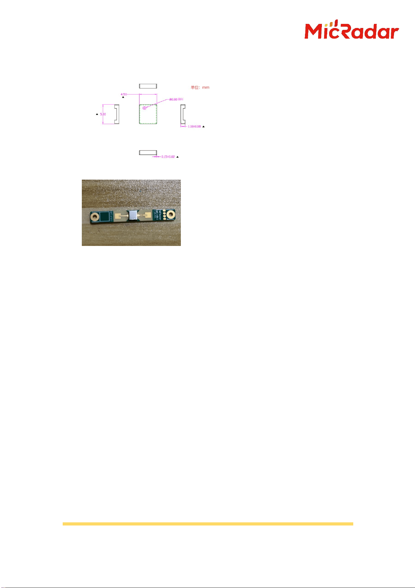
V. External Dimensions and Product
Photos
1) External dimensions: 6mm x 46mm
2) Fixing method: screw holes on both sides
3) Product photos
(a) Front view
(b) Back view photo
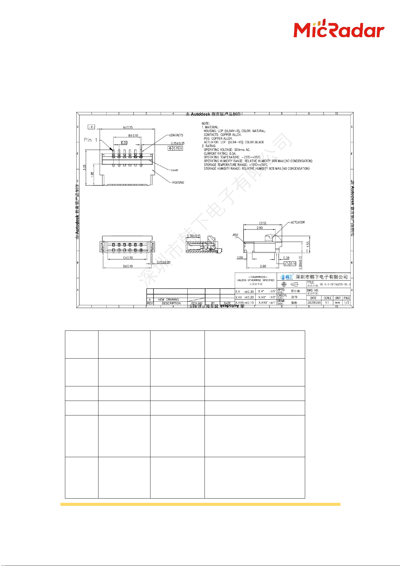
Note: A shielding cover is installed at the front radar chip location;
Shielding cover specifications: (Unit: mm)
HTTP : http://www.micradar.cn/
The final interpretation of this product belongs to Yunfan Ruida Technology ( Shenzhen ) Co.,
Ltd. Any changes will not be notified separately.
Shielding cover height: 1.2mm (height after SMT)
Front view photo:
VI. Installation and Usage
Instructions
This radar can be installed in the following ways: side wall mounting.
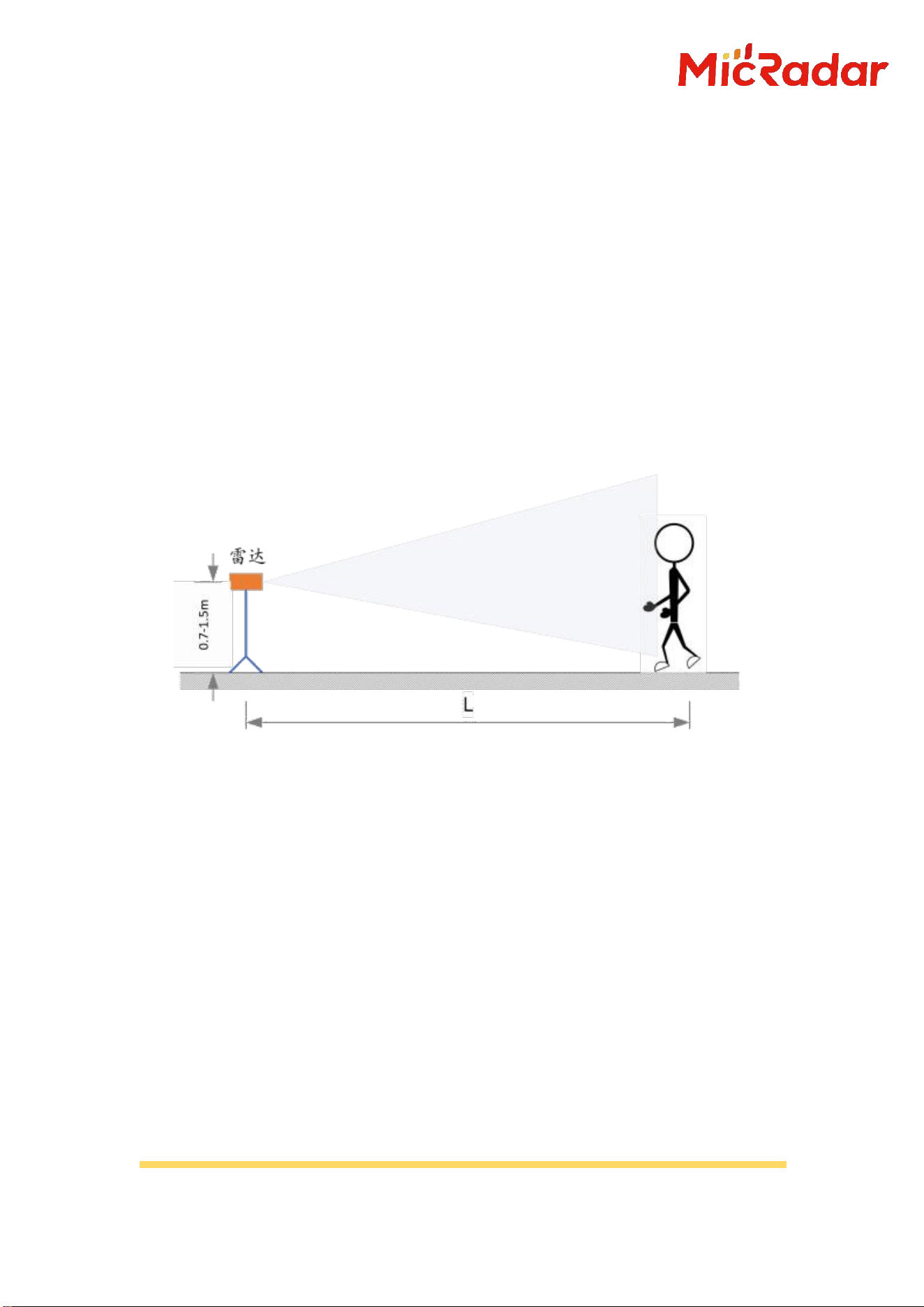
1: Horizontal installation
The image below shows a horizontal installation method. This
installation method is mainly for detecting human bodies while they
are standing , such as in the application of conference screens inside
and outside doors .
The recommended installation height for radar is 1.2 meters to 1.5
meters. Meters, the radar is installed horizontally and facing forward.
There are no obvious obstructions or coverings directly in front of
the radar.
The radar's normal direction is aligned with the main detection
position to ensure that the radar antenna's main beam covers the
HTTP : http://www.micradar.cn/
The final interpretation of this product belongs to Yunfan Ruida Technology ( Shenzhen ) Co.,
Ltd. Any changes will not be notified separately.
detection area, and the radar... The beam can cover the airspace where
people are active.
Due to the limitations of radar antenna beam range, the effective
range will decrease if the position deviates from the radar normal
direction.
Millimeter-wave electromagnetic waves have a certain penetrating
characteristic for non-metallic materials. They can penetrate common
glass, wood, screens, and thin partitions, and can detect moving
objects behind obstructions; however, they cannot penetrate thicker
load-bearing walls, metal doors, etc.
picture 1 Horizontal installation diagram
Notice:
A. All of the above installation methods require the radar main beam
to cover the main activity area of the human body and to be aligned with
the normal direction as much as possible;
B. When installed at an angle, the horizontal effective distance will
decrease accordingly due to the change in the horizontal projection of
the covered area;
C. When the module is working, there should be no metal objects
obstructing the module surface;

HTTP : http://www.micradar.cn/
The final interpretation of this product belongs to Yunfan Ruida Technology ( Shenzhen ) Co.,
Ltd. Any changes will not be notified separately.
D. Due to the influence of electromagnetic wave transmission
characteristics, the effective range of radar is related to the target's
RCS, the material and thickness of the target's covering material, and
the effective range of radar will vary to some extent.
E. For human body detection in a stationary state, different body
positions will affect the radar's effective range. The radar does not
guarantee that it will reach the maximum effective range in all states.
VII. Precautions
7.1. Radar biological detection performance
Because human biometrics are ultra-low frequency, weakly reflective
signals, radar processing requires relatively long processing times.
Intermittent accumulation processing involves numerous factors that can
affect radar parameters during the accumulation process, thus leading to
occasional detection failures. The effect is normal.
7.2. power supply
Radar modules have higher power quality requirements than
conventional low-frequency circuits. When powering the module, the power
supply must be free of threshold glitches or ripples, and effectively shield
power noise from accessory devices.
The radar module requires proper grounding. Ground noise from other
circuits can also cause issues with the radar module. Performance
degradation or even malfunction; most commonly, it leads to a shorter
detection range or an increased false alarm rate.
To ensure the internal VCO of the module For the circuit to function
normally, this module requires a power supply of +5V to +6V. Electrical

HTTP : http://www.micradar.cn/
The final interpretation of this product belongs to Yunfan Ruida Technology ( Shenzhen ) Co.,
Ltd. Any changes will not be notified separately.
voltage ripple ≤100mV. The external power supply must provide sufficient
current output capability and transient response capability.
VIII. Frequently Asked Questions
Interference factors: Radar is an electromagnetic wave detection
sensor, and moving inanimate objects can cause false alarms. The movement
of metals and liquids can also lead to false detections. Typically, electric
fans, pets close to the radar, and the swaying of metal curtains can all
cause false alarms. This can lead to misjudgments. Radar installation
angles need to be carefully planned.
Non-interference factors: Radar electromagnetic waves can penetrate
clothing, curtains, thin wood panels, and glass. The installation angle
and performance of the radar need to be determined based on the
application .
Semi-interference factors: Radar cannot detect the presence of a human
body by directly facing an air conditioner. The movement of air
conditioner fan blades and significant vibrations from some air
conditioners can cause radar misjudgments. Therefore, radar products
should not be directly facing the air conditioner, or should be
positioned in the same direction as the air conditioner.
IX. Disclaimer
Our company believes in ensuring the accuracy of document descriptions
during publication. Considering the technical complexity of the product...
Due to the complexity and differences in working environments, it is still
difficult to rule out some inaccurate or incomplete descriptions; therefore,
this document... For user reference only. Our company reserves the right
to make changes to the product without notifying the user. Our company makes
no legal promises or guarantees. Customers are encouraged to check the
HTTP : http://www.micradar.cn/
The final interpretation of this product belongs to Yunfan Ruida Technology ( Shenzhen ) Co.,
Ltd. Any changes will not be notified separately.
latest updates on our products and support tools. New suggestions were put
forward.
X. Copyright Notice
The components and devices mentioned in this document are all
references to information published by their respective copyright holders.
The rights to modify and publish this content belong to its copyright holder.
Please verify the copyright information through appropriate channels
before using it. Regarding the updates and errata information, our company
has no rights or obligations to these documents .
XI. Contact Information
Yunfan Ruida Technology (Shenzhen) Co., Ltd.
Email address: sales@micradar.cn
Telephone: 0755-88602663 Address: Room 501, West Tower, Phase II, Tianan
Innovation Technology Plaza, Futian District, Shenzhen
XII. Historical Version Update Notes
Revision
Release Data
Summary
V1.0_ 0827
2025/8/27
First draft
V1.1_1013
2025/10/13
Added UID query protocol
V1.2_1203
2025/12/03
Modify product photos and
operating temperature
V1.3_1231
2025/12/31
The corrected bandwidth
range is 200M.
V1.4_0108
2026/1/8
Added specifications for
the shielding cover on the

HTTP : http://www.micradar.cn/
The final interpretation of this product belongs to Yunfan Ruida Technology ( Shenzhen ) Co.,
Ltd. Any changes will not be notified separately.
radar module
V1.5_0120
2026/1/20
The new radar shield has
been adjusted to 1.2mm
(illustrated), and the
production test energy
value protocol has been
updated.
V1.6_0423
2026/4/23
1: Added firmware version
information for
Atari/Nintendo models
2: Added performance
specifications for the
detection range of
Nintendo models

KDB 996369 D03 statements
2.2 List of applicable FCC rules:
The module complies with FCC Part 15.249.
FCC ID: 2BVOV-R01 on User manual and on the external of the packaging.
2.3 Summarize the specific operational use conditions
The module has been certified for Potable applications. This transmitter must not beco-located or operating in
conjunction with any other antenna or transmitter
2.4 Limited module procedures
The module is not a limited module.
2.5 Trace antenna designs
Not applicable
2.6 RF exposure considerations
This equipment complies with FCC’s RF radiation exposure limits set forth for an uncontrolled environment. The
antenna(s) used for this transmitter must not be collocated or operating in conjunction with any other antenna or
transmitter.
2.7 Antennas
The EUT use a permanently attached antenna
which is unique.
2.8 Label and compliance information
The host system using this module, should have label in a visible area indicated the
following texts: “Contains FCC ID: 2BVOV-R01
2.9 Information on test modes and additional testing requirements
When testing host product, the host manufacture should follow FCC KDB Publication 996369 D04 Module Integration
Guide for testing the host products. The host manufacturer may operate their product during the measurements. In
setting up the configurations, if the pairing and call box options for testing does not work, then the host product
manufacturer should coordinate with the module manufacturer for access to test mode software.
The module has been certified for Potable applications. This transmitter must not be co-located or operating in
conjunction with any other antenna or transmitter
2.10 Additional testing, Part 15 Subpart B disclaimer
The module without unintentional-radiator digital circuity, so the module does not
require an evaluation by FCC Part 15 Subpart B. The host shoule be evaluated by the FCC Subpart B.
2.11 Note EMI Considerations
host manufacture is recommended to use D04 Module Integration Guide recommending as "best practice" RF design
engineering testing and evaluation in case non-linear interactions generate additional non-compliant limits due to
module placement to host components or properties
2.12 How to make changes
This module is stand-alone modular. If the end product will involve the Multiple simultaneously transmitting condition
or different operational conditions for a stand-alone modular transmitter in evaluation (i.e., no C2PC required when no
emission exceeds the limit of any individual device (including unintentional radiators) as a composite. The host
manufacturer must fix any failure
a host, host manufacturer have to consult with module manufacturer for the installation method in end system.
According to the KDB 996369 D02 Q&A Q12, that a host manufacture only needs to do anevaluation (i.e., no C2PC
required when no emission exceeds the limit of any individual device(including unintentional radiators) as a
composite. The host manufacturer must fix any failure