ユーザーズマニュアル
電波障害自主規制について
注意
この装置は、クラス A 情報技術装置です。この装置を家庭環境で使用すると
電波妨害を引き起こすことがあります。
この場合には使用者が適切な対策を講ずるよう要求されることがあります。
VCCI-A
はじめに
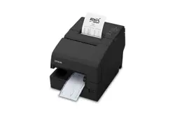
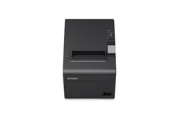
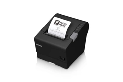
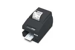
本書は、TM シリーズプリンター ( インターフェイス基板対応 ) に取り付けら
れているインターフェイス基板の交換方法について説明しています。イン
ターフェイス基板交換後は、プリンターの設定の確認、または設定が必要に
なります。その際は、プリンターのマニュアルをご覧ください。
本製品ご使用の場合、TM プリンターのディスプレイモジュール(カスタマー
ディスプレイ)コネクターは使用できませんので、ご注意ください。
本書の記号の見方について
本書では、以下の記号が使われています。記号の意味をよく理解してから交
換作業をしてください。
注意:
この表示を無視して、誤った取り扱いをすると、人が傷害を負う可能性が想
定される内容および物的損害のみの発生が想定される内容を示しています。
交換作業上の注意
注意:
❏
作業の前にプリンターから電源を取り外してください。( 電源スイッチ
をオフにするだけでなく、電源を取り外してください。)
プリンターの電源スイッチをオフにしても、内部の回路基板には通電し
ているところがあります。電源を取り付けたまま交換作業を行うと、イ
ンターフェイス基板、およびプリンターが故障する可能性があります。
Copyright セイコーエプソン株式会社 2008
Printed in China
❏
作業中は接地されたリストバンドを装着してください。
リストバンドを装着せずに作業をすると、静電気による故障の原因にな
ります。
❏
インターフェイス基板のコネクターを手で触れないでください。汚れに
よる動作不良を起こす可能性があります。
同梱品
❏ UB-P02II
❏ 本書
交換手順
1. インターフェイス基板を固定している 2 つのネジを外して、インター
フェイス基板を抜き取ります。取り外したネジは、UB-P02II を固定する
時に再び使用します。
注意:
取り外したインターフェイス基板は、静電気による故障を防ぐため、静
電防止処理をした袋などに保管してください。
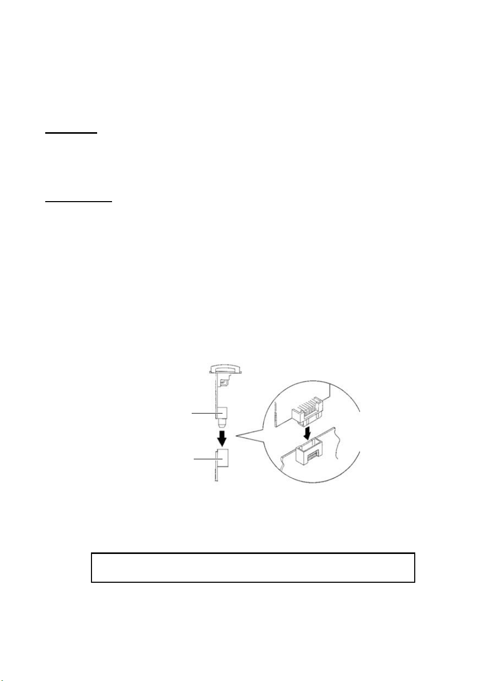
2. 図のように UB-P02II のコネクターをプリンターのコネクターに合わせま
す。UB-P02II を押してコネクターを接続してください。
3. 2 つのネジで U-P20II を固定します。
4. 新しいインターフェイスに合わせて、プリンターの設定を変更します。
設定の説明については、プリンターのマニュアルを参照してください。
設定は必ず行ってください。プリンターが正しく動作しないことが
あります。
UB-P02II のコネクター
TM プリンターの
コネクター
User’s Manual
Copyright 2008 by Seiko Epson Corporation
Printed in China
Standards and Approvals
Introduction
This manual describes how to replace the interface board on TM series printers
designed for the UB-P02II. You must check the printer settings after replacing the
interface board. See the documentation that came with the printer for information
about the settings.
When you use the UB-P02II, note that you will not be able to use the display
module (customer display) connector of the printer.
About the Symbol in This Manual
CAUTION:
Cautions must be observed to avoid minor injury to yourself or damage to
your equipment.
The following standards are also applied only to the
units that are so labeled. (EMC is tested using the
EPSON power suppliers and TM series printer.)
Europe: CE marking
North America: FCC/ICES-003 Class A
Japan: VCCI Class A
Oceania: AS/NZS CISPR22 Class A
WARNING
This is a Class A product. In a domestic environment
this product may cause radio interference, in which
case the user may be required to take adequate
measures. The printers in which this board is installed
becomes class A devices.
The connection of a non-shielded printer interface cable
to this board will invalidate the EMC standards of this
device.
You are cautioned that changes or modifications not
expressly approved by Seiko Epson Corporation could
void your authority to operate the equipment.
CE Marking
The board conforms to the following Directives and
Norms:
Directive 2004/108/EC
EN 55022 Class A
EN 55024
IEC 61000-4-2 IEC 61000-4-5
IEC 61000-4-3 IEC 61000-4-6
IEC 61000-4-4 IEC 61000-4-11
FCC Compliance Statement For
American Users
This equipment has been tested and found to comply
with the limits for a Class A digital device, pursuant to
Part 15 of the FCC Rules. These limits are designed to
provide reasonable protection against harmful
interference when the equipment is operated in a
commercial environment.
This equipment generates, uses, and can radiate radio
frequency energy and, if not installed and used in
accordance with the instruction manual, may cause
harmful interference to radio communications.
Operation of this equipment in a residential area is likely
to cause harmful interference, in which case the user will
be required to correct the interference at his own expense.
For Canadian Users
This Class A digital apparatus complies with Canadian
ICES-003.
À l'intention des utilisateurs
canadiens
Cet appareil numérique de classe A est conforme à la
norme canadienne NMB-003.
Precautions
CAUTION:
Disconnect the power supply from the printer before you remove the
interface board; otherwise you may damage the interface board and the
printer. You must disconnect the power supply because the electrical
current is flowing in some parts of the printer circuit even when the power
switch is turned off.
Wear a grounded wrist strap when handling the interface board to prevent
damage from static electricity.
To avoid contamination, do not touch the board connector.
Unpacking
Make sure you have these items:
❏ UB-P02II
❏ This manual
Procedure
1. Remove the two screws that securing the interface board; then pull the board
to remove it. You will use the screws when installing the UB-P02II.
CAUTION:
Put the removed interface board into an anti-static bag for storage to
prevent damage from static electricity.
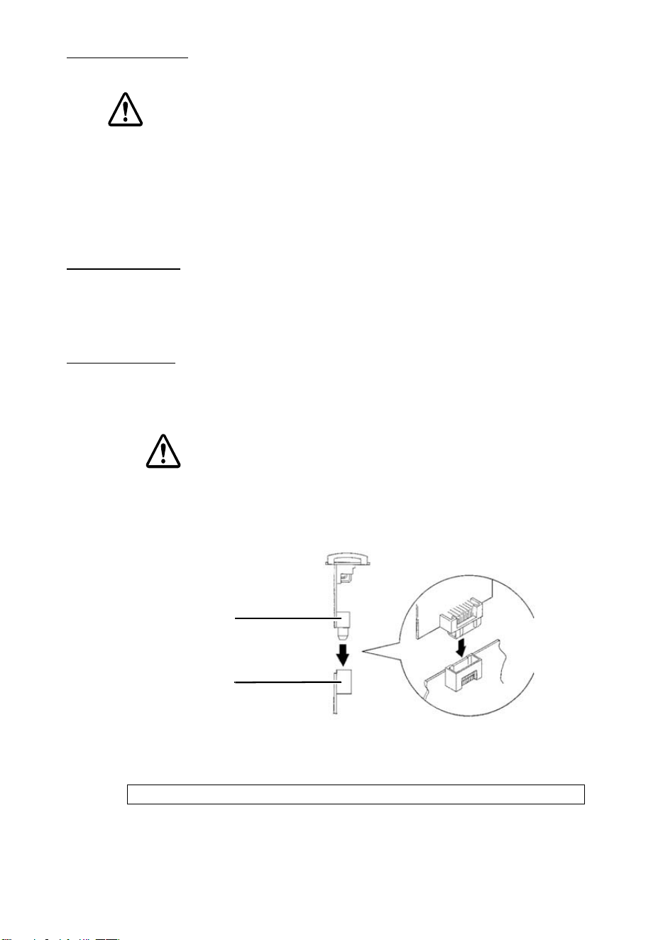
2. Hold the UB-P02II as shown in the illustration below. Push the UB-P02II in
gently until you feel the connector fit into place.
3. Secure the UB-P02II with the two screws.
4. Change the printer settings to match the printer to the new interface.
See the printer documentation for the settings.
Make sure you set the printer settings. Otherwise the printer may not work correctly.
Connector of
the UB-P02II
Connector of
the TM printer