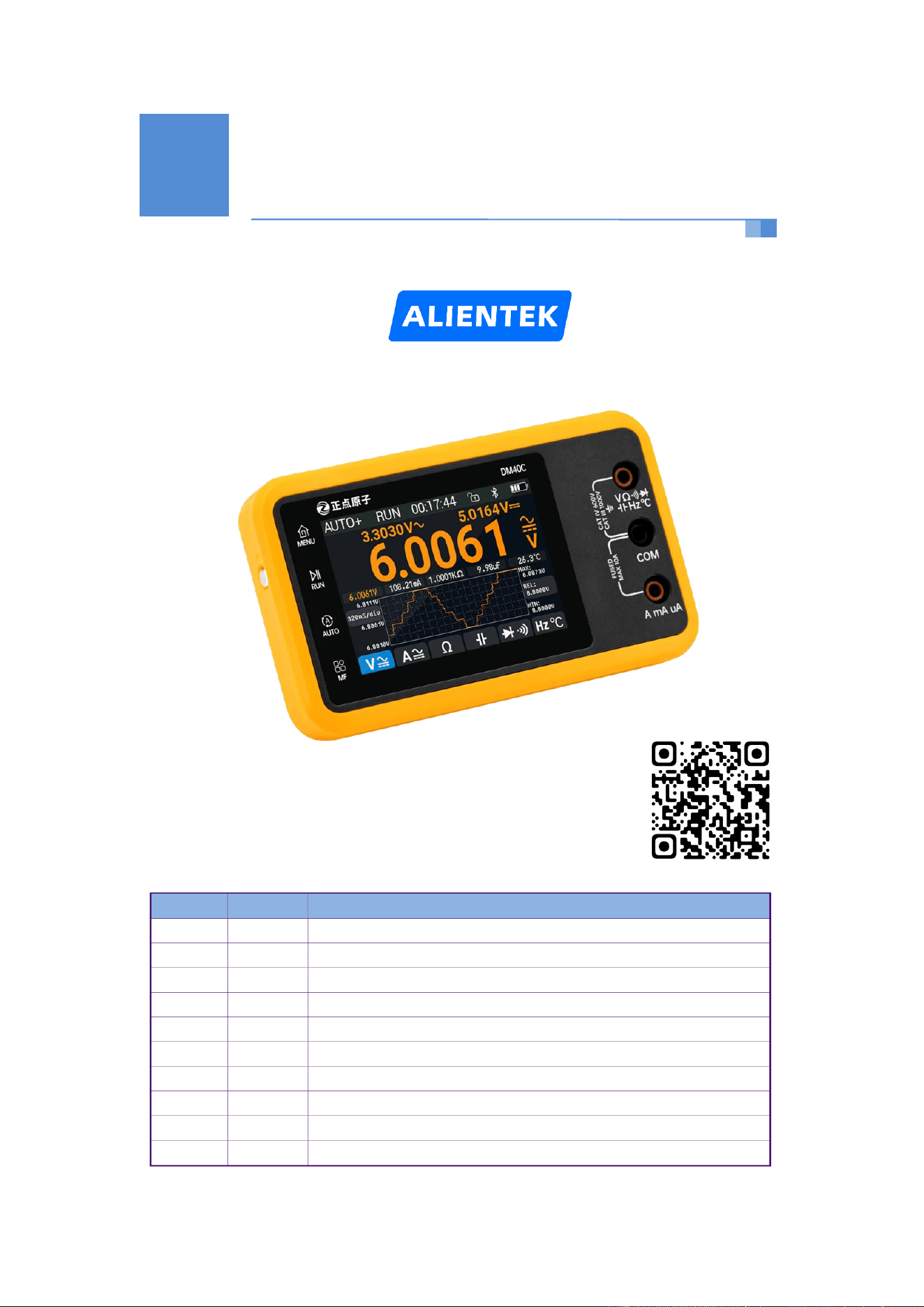
User Manual
Touchable Multimeter 3-IN-1
DM40 Multimeter User Manual
Revision History
Version
Date
Modify Contents
V1.0
2024/12/07
First release
V1.1
2024/12/11
Added firmware upgrade, custom boot logo, quick screenshot instructions
V1.2
2024/12/13
Added multimeter measurement settings instructions, added AUTO+ mode
V1.3
2024/12/25
Added data record, resistor mode settings, shockproof mode, slide to shutdown
V1.4
2025/01/18
Added mode memory, quick mode switch of resistor, countdown shutdown
V1.5
2025/03/24
Add Bluetooth function description and add custom boot logo explanation
V1.6
2025/09/17
Update the Bluetooth instructions and the continuity funcition descriptions
V1.7
2025/10/29
Replace RLE pictures to REL pictures
V1.8
2025/12/16
Modify the parameters of the signal generator and probe
User
Manual

Touchable Multimeter 3-IN-1
用户手册 www.alientek.com
1
DM40 Multimeter User Manual
Contents
Safety Instructions (Must Read)................................................................................. 1
1,Product Introduction...................................................................................... 1
2,Quick Start ....................................................................................................... 4
2.1 Appearance Description ............................................................................................... 4
2.2 Multimeter Measurement Interface ........................................................................... 5
2.2.3,Value of measurement ..................................................................................... 5
2.2.4,Mode Setting Buttons ..................................................................................... 6
2.2.5,Data Recording ................................................................................................. 6
2.3 Measurement Mode Description ................................................................................... 6
2.4 Measurement Port Description ................................................................................... 7
2.5 Measurement Methods ..................................................................................................... 7
2.5.1 Voltage Measurement ......................................................................................... 7
2.5.2 Current Measurement ......................................................................................... 7
2.5.3 Resistance Measurement ................................................................................... 8
2.5.4 Capacitance Measurement ................................................................................. 8
2.5.5 Diode/Continuity Measurement ....................................................................... 8
2.5.6 Frequency/Temperature Measurement ............................................................. 8
2.6 Measurement Settings ................................................................................................... 9
2.6.1 Voltage and Current Measurement Settings ............................................... 9
2.6.2 Resistance Measurement Settings ................................................................. 9
3,Oscilloscope & Signal Generator Usage Instructions .......................... 10
4,Other Functions ..............................................................................................11
4.1 System Settings ........................................................................................................... 11
4.2 Firmware Update Instructions ................................................................................. 11
4.3 Custom Boot Logo ......................................................................................................... 11
4.4 Quick screenshot instructions ............................................................................... 11
4.5 Anti-drop Mode Instructions ................................................................................... 12
4.6 Slide to Shutdown and Auto-shutdown Instructions ......................................... 12
4.7 Mode Memory Functions ............................................................................................... 13
4.8 Bluetooth Function ..................................................................................................... 13
5,Services ............................................................................................................. 14

Touchable Multimeter 3-IN-1
用户手册 www.alientek.com
1
DM40 Multimeter User Manual
Thank you for purchasing this product. To fully understand its features and operation, we
recommend reading this manual carefully before use.
Safety Instructions (Must Read)
1, Before using DM40, please check carefully if the shell has cracks or defects, and ensure the
measurement ports and accessories are normal.
2, DM40 integrates a rechargeable battery. For safety and measurement stability, please do not
measure while charging. Low battery reminders may affect accuracy. Please charge promptly.
3, Please select the correct measurement port, range, and scale to avoid damaging the instrument
or causing personal injury!
4, Hold the probe at the protected position. Do not hold the metal part for measurement!
5, Do not disassemble the case at will or measure while the case is open.
6, Do not use in environments with flammable or explosive gases/materials or in damp
conditions.
7, For voltage measurement, when used for DCDC or high voltage above 36V measurement, it is
recommended to use AUTO+ mode to skip the mV range (to avoid mismeasurement, sparking,
and protection) and start measurement from the V range.
8, To use the Bluetooth function, please go to Settings > Other Settings, turn on the Bluetooth,
return to Multimeter interface,and then connect via the APP(atk-xtool).
1,Product Introduction
The DM40 digital multimeter is the first high-performance 3-in-1 multimeter launched by
Guangzhou Xingyi Electronic Technology Co., Ltd. Its main features are as follows:
① Integrated multimeter, oscilloscope, and signal generator, featuring comprehensive functions
and convenient measurement.
② Equipped with a 3.5-inch 480*320 IPS capacitive touchscreen, providing delicate display and
convenient interaction.
③ 4-5/6 multimeter with a count of up to 60000 (C version), TRMS true RMS measurement,
precise and reliable.
④ Automatic mV/V range and innovative uA/mA/A range design for quick and efficient
measurement.
⑤ AC+DC mixed measurement (B/C versions), no signal escapes detection.
⑥ Super diode measurement with multi-segment beep design, quick response, and support for
resistance (<1KΩ) measurement.
⑦ Supports resistance, capacitance, continuity, frequency, temperature, and other measurements.
⑧ Supports manual (V/A/Ω)/automatic range, REL relative measurement, extreme value
measurement, data hold.
⑨ Supports trend chart display for efficient data analysis with 3 adjustable time bases.
⑩ Oscilloscope with 50MSa/s sampling rate, 10MHz bandwidth, and 10-bit vertical resolution.
Touchable Multimeter 3-IN-1
用户手册 www.alientek.com
2
DM40 Multimeter User Manual
○
11
Oscilloscope supports multiple trigger modes and types, as well as FFT and ABS operations.
○
12
Signal generator supports sine wave, sawtooth wave, triangle wave, and square wave up to
10MHz.
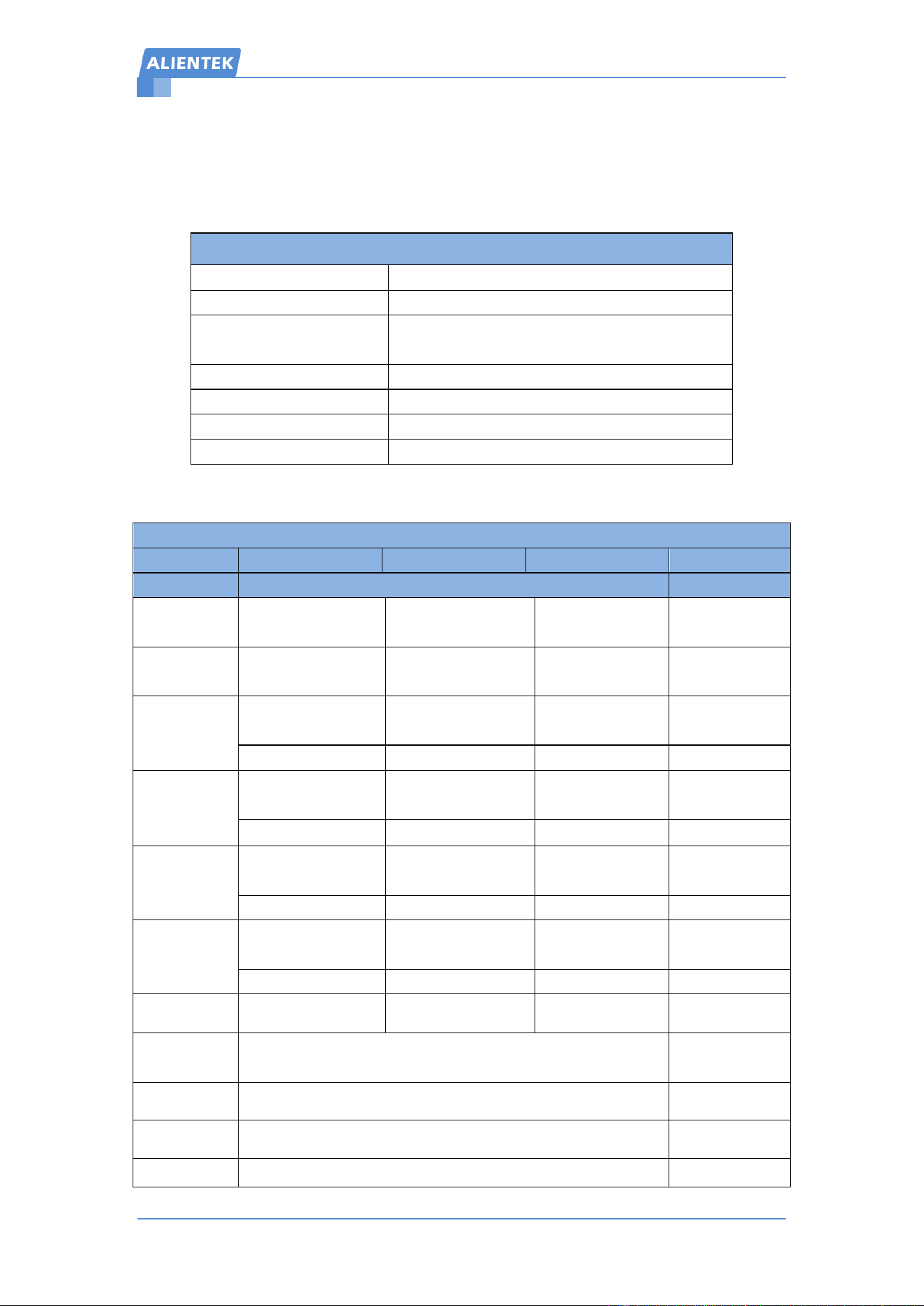
DM40 Basic Parameters:
Basic Information
Model
DM40A、DM40B、DM40C
Screen
3.5'(480*320) IPS Touchscreen
Battery Life
≈12H(Multimeter)
≈10H(Oscilloscope)
Dimensions
142 * 83 * 28mm
Weight
≈260g
Interface
USB TypeC/MCX Socket/Banana Jack Socket
Conditions
Temperature 0~40℃、Humidity <75%
Table 1.0 DM40 Basic information
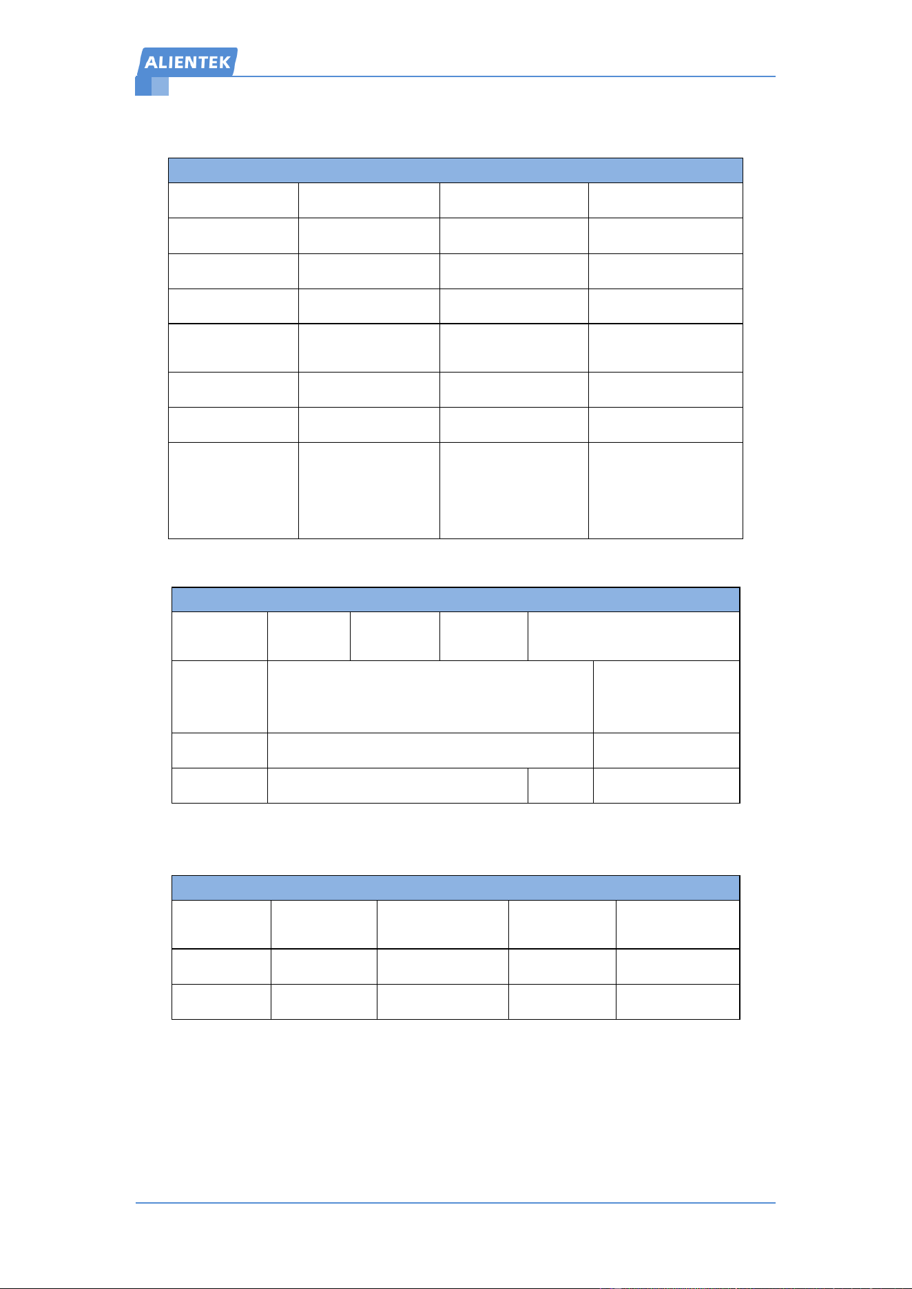
DM40 Multimeter Technical Parameters:
Multimeter Technical Parameters
Model
DM40A
DM40B
DM40C
Function
Range
Accuracy
DC Voltage
400mV/4V/40V
/400V/1000V
500mV/5V/50V
/500V/1000V
600mV/6V/60V
/600V/1000V
±(0.03%+5d)
AC Voltage
400mV/4V/40V
/400V/750V
500mV/5V/50V
/500V/750V
600mV/6V/60V
/600V/750V
±(0.3%+15d)
DC Current
400uA/4000uA
/40mA/400mA
500uA/5000uA
/50mA/500mA
600uA/6000uA
/60mA/600mA
±(0.15%+5d)
4A/10A
5A/10A
6A/10A
±(0.2%+5d)
AC Current
400uA/4000uA
/40mA/400mA
500uA/5000uA
/50mA/500mA
600uA/6000uA
/60mA/600mA
±(0.5%+15d)
4A/10A
5A/10A
6A/10A
±(0.75%+15d)
Resistor
400Ω/4KΩ/40KΩ
/400KΩ/4MΩ
500Ω/5KΩ/50KΩ
/500KΩ/5MΩ
600Ω/6KΩ/60K
Ω/600KΩ/6MΩ
±(0.1%+5d)
40MΩ
50MΩ
60MΩ
±(0.2%+10d)
Capacitance
4nF/40nF/400nF
/4uF/40uF
5nF/50nF/500nF
/5uF/50uF
6nF/60nF/600nF
/6uF/60uF
±(2.5%+30d)
400uF/4mF/40mF
500uF/5mF/50mF
600uF/6mF/60mF
±(3.5%+30d)
Frequency
10Hz~40MHz
10Hz~50MHz
10Hz~60MHz
±(0.01%+5d)
Temperature
-40℃~1000℃(Standard probe range -20℃~300℃)
-40℉~1832℉
±(1.0%+5℃)
±(1.5%+5℉)
Continuity
0Ω~1KΩ
±(0.2%+5d)
Diode
0V~3.0V, 0Ω~1KΩ
±(1%+5d)
AC Response
10KHz
Touchable Multimeter 3-IN-1
用户手册 www.alientek.com
3
DM40 Multimeter User Manual
Table 1.1 Multimeter Technical Parameters
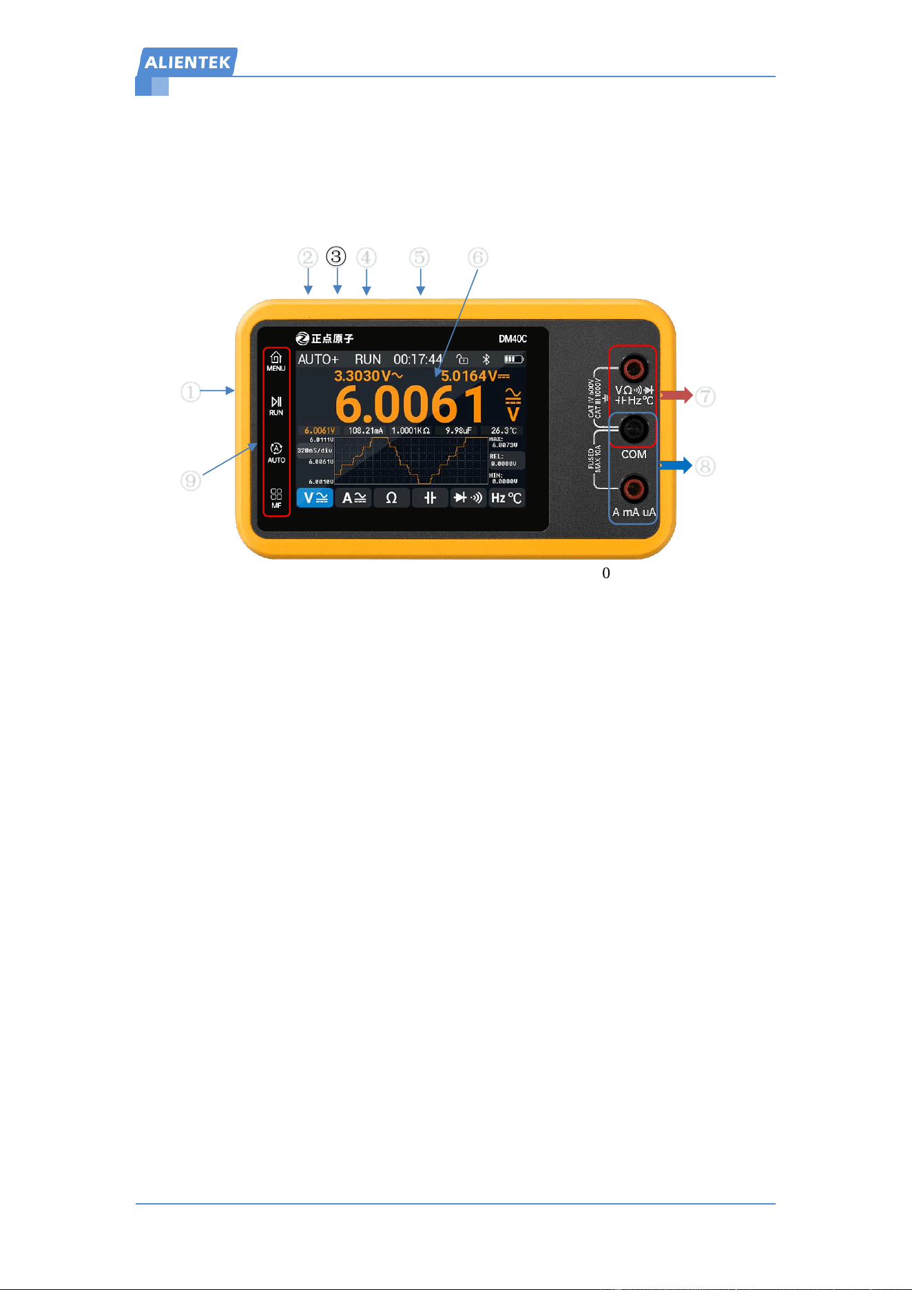
DM40 Oscilloscope Technical Parameters:
Oscilloscope Technical Parameters
Sample Rate
50MSa/S
Input lmpedance
1MΩ
Bandwidth
10Mhz
Timebase Mode
YT/ROLL
Memory Depth
64Kpts
Sweep Mode
Auto/Normal/Single
Time Scale
100ns~50s
Trigger Type
Rising/Falling
Vertical Scale
10mV~10V
/div(X1)
Persistence
OFF /Min/1S/∞
Resolution
10bit
Math
FFT/ABS
Coupling
AC、DC
Measurement items
20 types
Waveform
Capture Rate
150 wfms/s
Maximum measured
voltage
±40V(@X1)
±400V(@X10)
±4kV(@X100)
±40kV(@X1000)
Table 1.2 Oscilloscope Technical Parameters
DM40 Signal Generator Technical Parameters:
Signal generator Technical Parameters
Wave out
Sine Wave
Sawtooth
Wave
Triangle
Wave
Square Wave
Frequency
1Hz~50KHz
100KHz、200KHz、
500KHz、1MHz、
2MHz、5MHz、10MHz
Amplitude
0.5V~3.0Vpp
3.0Vpp
Duty
Not Adjustable
0~100%
Not Adjustable
Table 1.3 Signal Generator Technical Parameters
DM40 Adjustable MCX Probe Parameters:
Adjustable MCX Probe Parameters
Attenuation
Ratio
Bandwidth
Input Impedance
Input
Capacitance
Maximum
Voltage
X1
20MHz
1MΩ±2%
50pF±20pF
150VRMS CATⅡ
X10
140MHz
10MΩ±2%
15pF±5pF
300VRMS CATⅡ
Table 1.4 Adjustable MCX Probe Parameters
Touchable Multimeter 3-IN-1
用户手册 www.alientek.com
4
DM40 Multimeter User Manual
2,Quick Start
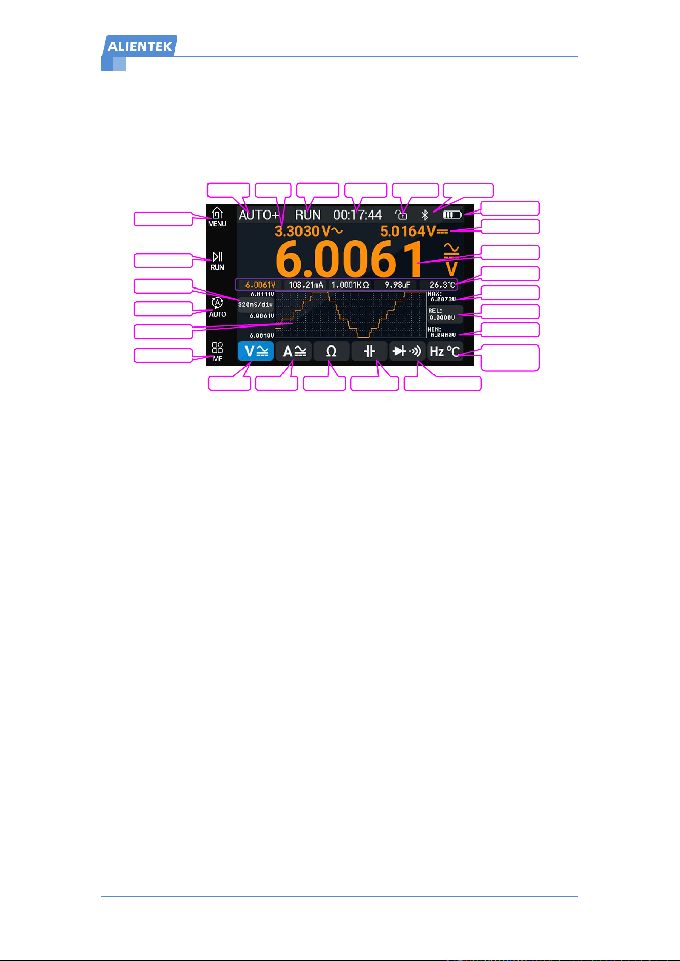
2.1 Appearance Description
Figure 2.1.1 Appearance and Interface of DM40
Description
① Power Button (Long press to turn on/off, double-click to lock/unlock touch)
② TypeC Port (For charging and USB communication, input voltage <5.2V)
③ Charging Indicator (Blue light when charging, off when fully charged)
④ MCX Signal Generator Port
⑤ MCX Oscilloscope Port
⑥ 3.5" (480*320) IPS Touchscreen
⑦ Voltage, Resistance, Capacitance, Continuity, Diode, Frequency, Temperature Measurement
Ports (Black COM is common)
⑧ Current Measurement Port (Black COM is common)
⑨ Multi-function Touch Buttons (MENU, RUN, AUTO, MF)
③
④
⑤
⑥
②
①
⑦
⑧
⑨
Touchable Multimeter 3-IN-1
用户手册 www.alientek.com
5
DM40 Multimeter User Manual
2.2 Multimeter Measurement Interface
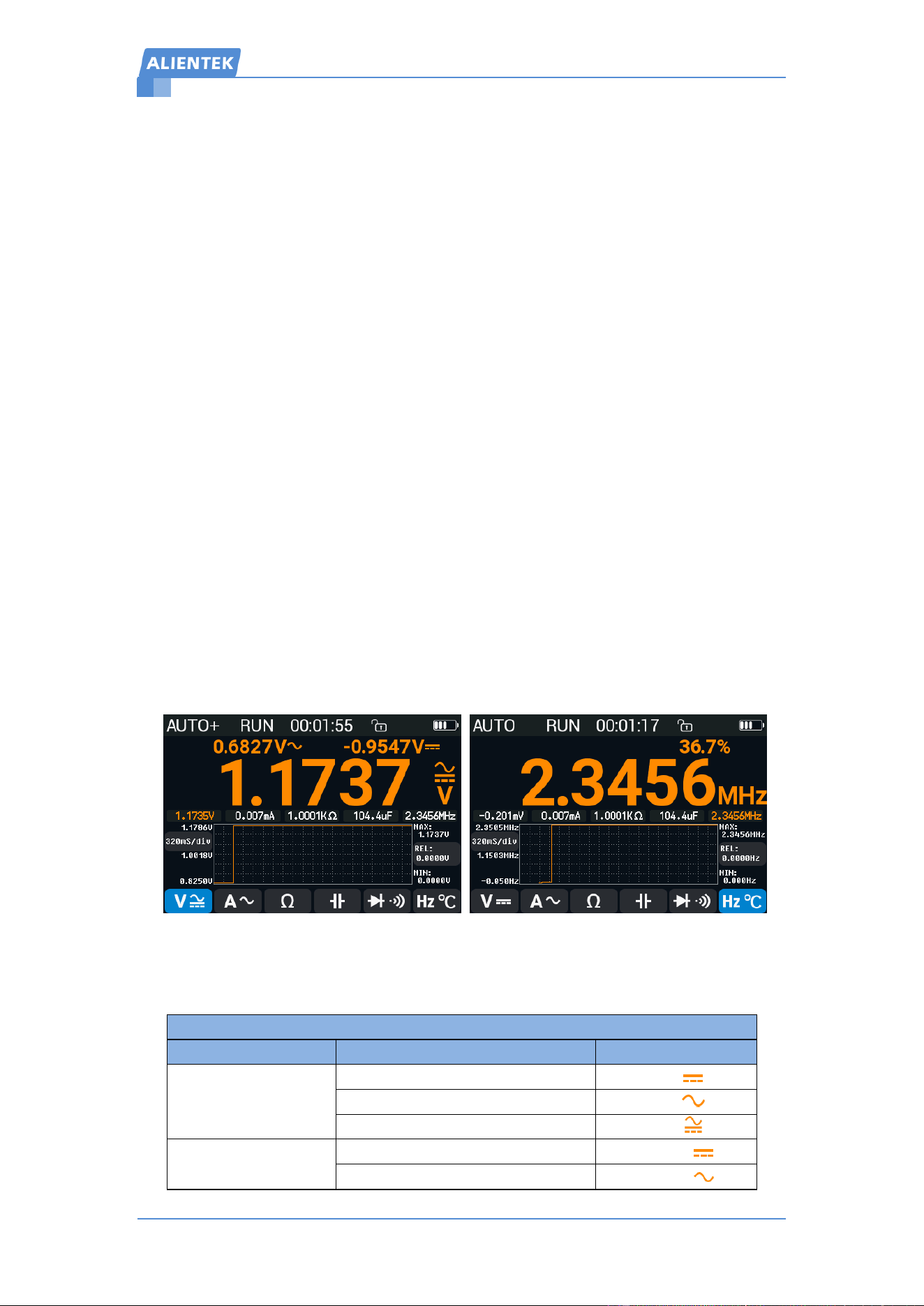
The multimeter interface displays rich content: top status bar; left 4 multi-function touch buttons;
middle for various measurement displays; bottom 6 touch buttons to switch 8 measurement
functions; as shown in Figure 2.2.1.
Figure 2.2.1 Multimeter measurement interface
2.2.1,Status Bar Description
Range Indication: AUTO range and manual range (only for voltage, current, resistance).
Running Status: RUN for running status, HOLD for data hold.
Uptime: Records uptime (in hours/minutes/seconds).
Touch Lock/Unlock: Double-click the power button to lock/unlock touch function. After locking,
touch is invalid. Single-click the power button can still switch measurement modes within the
current mode.
BT Status: After the APP is successfully connected, the Bluetooth icon appears and disappears
when disconnected
Battery Info: Displays battery level when not charging, charging progress when charging (Do not
measure while charging to avoid mismeasurement).
2.2.2,Left Touch Buttons
MENU: Click to return to the function interface or measurement interface.
RUN: Click to toggle RUN/HOLD mode. HOLD stops the interface from refreshing (except for
Uptime).
AUTO: Click to restore automatic range and turn off REL function.
MF: Enter/exit measurement settings (only for V/A/Ω). For voltage/current, select range first and
then AC/DC measurement. For resistance, select range and return to the measurement interface.
2.2.3,Value of measurement
Aux1: AC mode displays frequency, AC+DC mode displays AC component, temperature mode
displays machine temperature.
Aux2: AC mode and frequency mode display duty, AC+DC mode displays DC component, DC
mA range displays the percentage of the 4-20mA signal, diode mode displays equivalent resistance,
temperature mode displays Fahrenheit.
Main display: Displays measurement value and units.
Range
Run state
Uptime
BT Status
Aux1
Touch state
Min measure
Relative meas
Max measure
Main display
Diode/Continuity
Frequency /
Temperature
Resistor
Current
Capacitance
Voltage
Menu button
Time-base set
Run button
Auto measure
Meas setting
Wave display
Data record
Aux2 display
Battery Info
Touchable Multimeter 3-IN-1
用户手册 www.alientek.com
6
DM40 Multimeter User Manual
REL function: In non-OL and data hold states, click REL button to enable REL function and enter
manual range. Records main display value to REL. Then main display subtracts the REL value.
Click once to update. Click the AUTO button/switch measure mode/long-press the REL button to
turn off this function and restore automatic range.
MAX/MIN: Records the maximum and minimum measured values. Clears after changing
measurement modes;
Waveform Display: Synchronously displays the main display value. The waveform auto-scales,
with horizontal*vertical=20*6 grids. Time base options are 160mS/320mS/640mS. Default is
320mS/div;
2.2.4,Mode Setting Buttons
Voltage Measurement: Cycle through DCV mode, ACV mode, AC+DC mode (only DM40B/C).
Current Measurement: Cycle through DCA mode, ACA mode, AC+DC mode (only DM40B/C).
Resistance Measurement: Click to cycle through offline and online resistance measurement.
Online measurement is indicated by Ω with subscript ON.
Capacitance Measurement: Sets to capacitance measurement mode.
Diode/Continuity Measurement: Cycle through diode and continuity measurement.
Frequency/Temperature Measurement: Cycle through frequency and temperature measurement.
Note: Switching measurement modes restores AUTO/AUTO+ range and turns off REL function.
2.2.5,Data Recording
DM40 supports screen data recording. In non-OL state, short-press the main display number
area to record and update data once. A short beep indicates recording. The most recently updated
data is orange, and others are white. Supports up to 5 sets of data. Older data is overwritten.
Long-press the main display area for 1s to clear all records. A long beep indicates clearing.
2.3 Measurement Mode Description
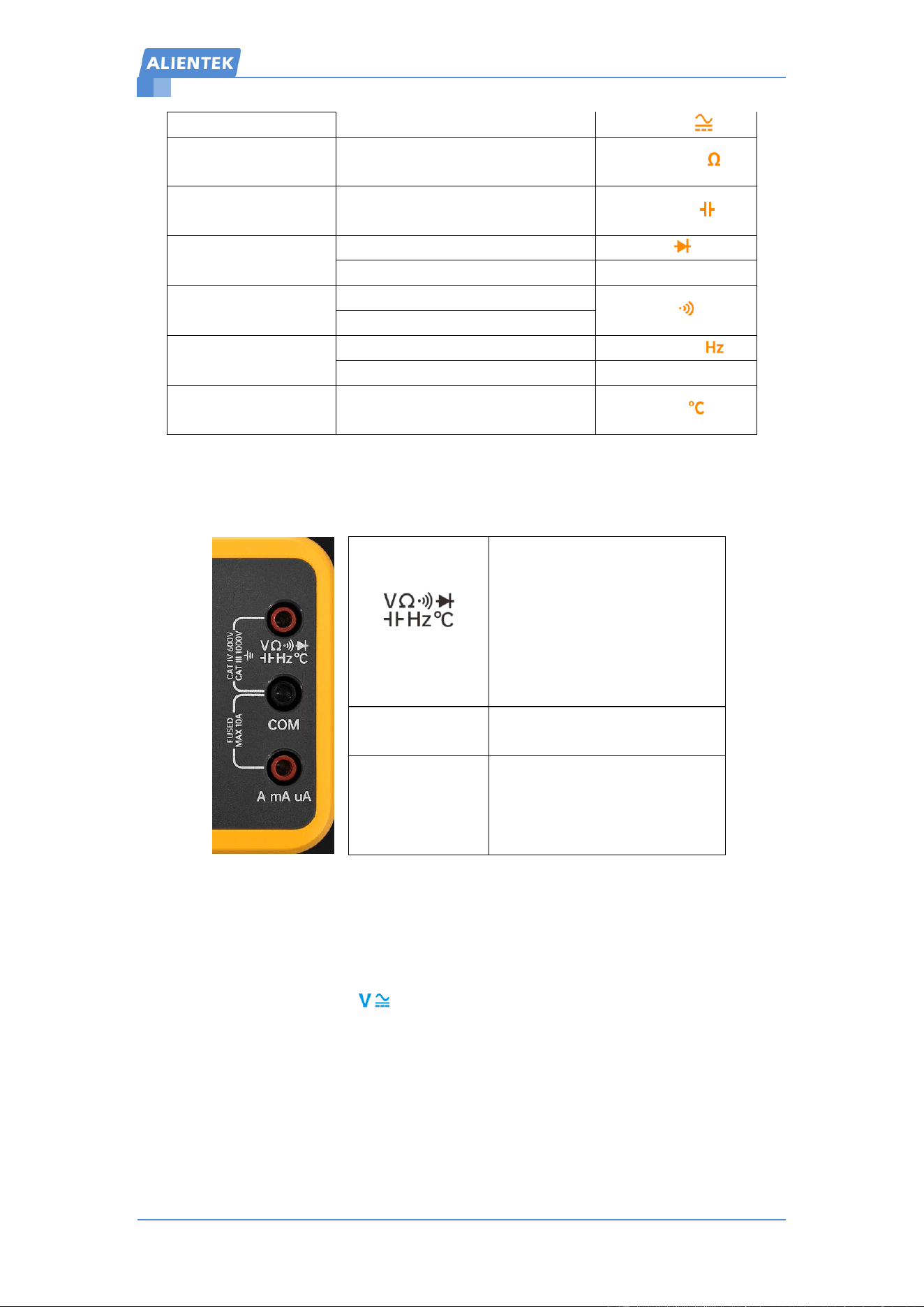
Measurement Mode Description:
Measurement Mode Description
Mode Category
Item Category
Unit+Symbol
Voltage
Measurement
DCV(DC Voltage Measurement)
mV/V
ACV(AC Voltage Measurement)
mV/V
AC+DC Mixed Measurement(DM40B/C)
mV/V
Current
Measurement
DCA(DC Current Measurement)
uA/mA/A
ACA(AC Current Measurement)
uA/mA/A
Touchable Multimeter 3-IN-1
用户手册 www.alientek.com
7
DM40 Multimeter User Manual
AC+DC Mixed Measurement(DM40B/C)
uA/mA/A
Resistance
Measurement
Resistance Measurement
(Offline/Online measurement)
Ω/KΩ/MΩ
Capacitance
Measurement
Capacitance Measurement
nF/uF/mF
Diode
Measurement
Diode Voltage Drop Measurement
V
Resistance Measurement
Ω
Continuity
Measurement
Continuity Measurement
Ω
Resistance Measurement
Frequency
Measurement
Frequency Measurement
Hz/KHz/MHz
Duty Measurement
%
Temperature
Measurement
Temperature Measurement
℃/℉
Table 2.3.1 Measurement Mode Description
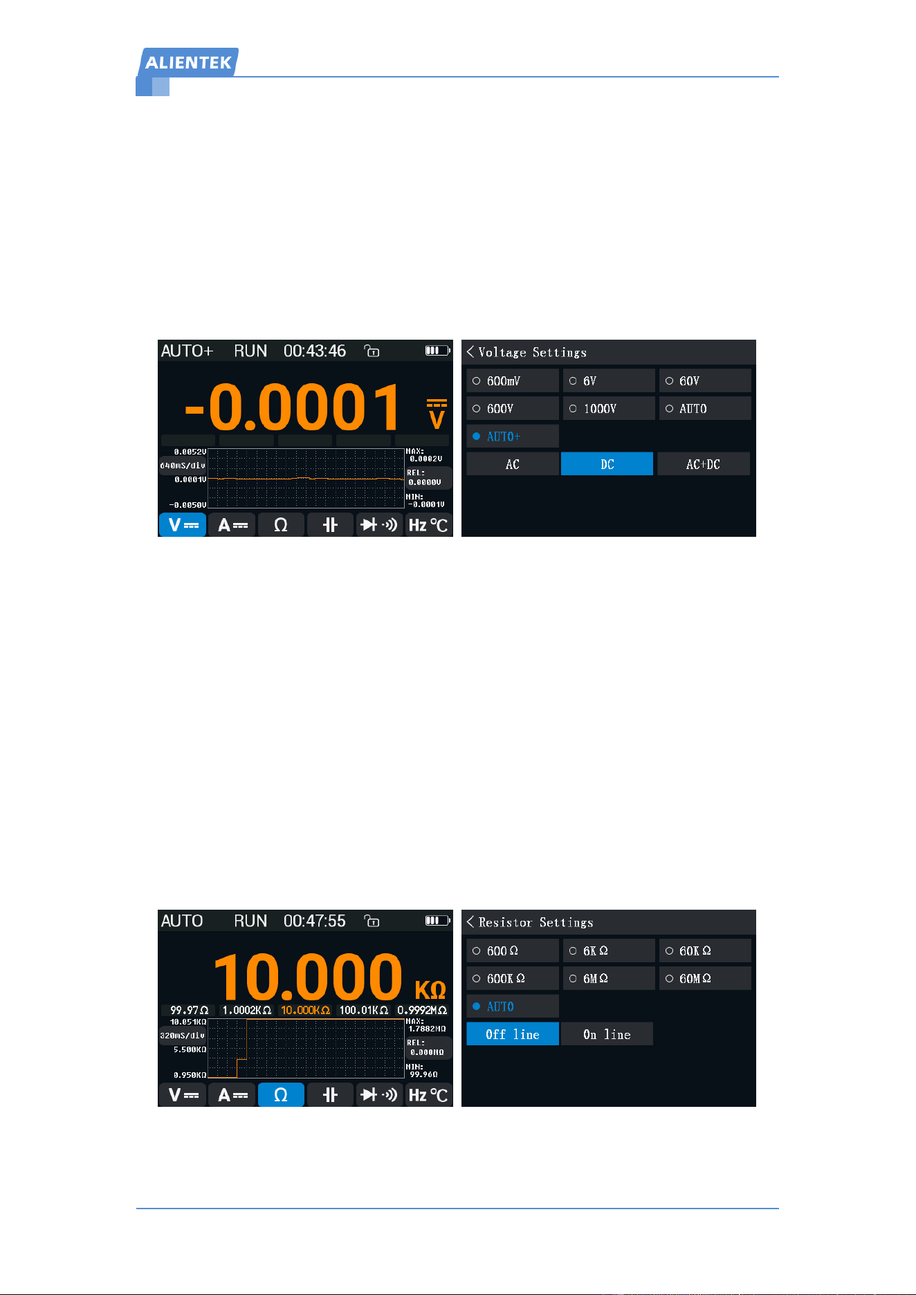
2.4 Measurement Port Description
Figure 2.4.1 Measurement Port Description
2.5 Measurement Methods
2.5.1 Voltage Measurement
① Click the voltage button( )to enter voltage measurement mode,Default is DC
measurement. Cycle through DCV/ACV/AC+DC measurement by clicking (only DM40B/C).
② Connect the black probe to the black COM port and the red probe to the red VΩHz port.
③ Connect the probes to the circuit under test and observe the measured value on the screen. OL
indicates out of range.
Note: Do not exceed the maximum measure value. Use auto range if unsure of the voltage range.
2.5.2 Current Measurement
(Red Terminal)
1. AC/DC voltage measurement
2. Resistance measurement
3. Continuity measurement
4. Diode measurement
5. Capacitance measurement
6. Frequency measurement
7. Temperature measurement.
COM
(Black Terminal)
Common port for all
measurements
A mA uA
(Red Terminal)
Dedicated port for current
measurement, 10A(Max)
Built-in 10A ceramic fuse. Replace
with the same model if burned

Touchable Multimeter 3-IN-1
用户手册 www.alientek.com
8
DM40 Multimeter User Manual
① Click the current button( ) to enter current measurement mode. Default is DC
measurement. Cycle through DCA/ACA/AC+DC measurement by clicking (only DM40B/C).
② Connect the black probe to the black COM port and the red probe to the red A mA uA port.
③ Connect the probes to the circuit under test and observe the measured value on the screen. OL
indicates out of range.
Note: Do not exceed the maximum measure value(10A). Use auto range if unsure of the current
range.
2.5.3 Resistance Measurement
① Click the resistance button(Ω)to enter resistance measurement mode.
② Connect the black probe to the black COM port and the red probe to the red VΩHz port.
③ Connect the probes to the resistor under test and observe the measured value on the screen. OL
indicates out of range.
Note: It is recommended to use online measure mode for online measurement.
2.5.4 Capacitance Measurement
① Click the capacitance button( )to enter capacitance measurement mode. Capacitance
measurement only supports automatic range.
② Connect the black probe to the black COM port and the red probe to the red VΩHz port.
③ Discharge the capacitor in advance, then connect the probes to the capacitor under test and
observe the measured value on the screen. OL indicates out of range. Testing large mF capacitors
takes longer, which is normal.
Note: Do not perform voltage measurement in this mode to avoid damaging the instrument.
2.5.5 Diode/Continuity Measurement
① Click the diode/buzzer button( )to enter diode measurement mode. Click again to switch
to continuity measurement.
② Connect the black probe to the black COM port and the red probe to the red VΩHz port.
③ Connect the probes to the component under test. Diode measurement supports 4-segment
beeps (<0.02V long beep, <0.45V two short beeps, <0.75V one short beep, <1.5V urgent three
short beeps). Maximum voltage drop display is around 3.1V. OL is displayed if exceeded. Also
supports resistance measurement within 1KΩ,OL displayed if exceeded. Approximately within
15Ω, the buzzer beeps continuously。
Note: Do not perform voltage measurement in this mode to avoid damaging the instrument.
2.5.6 Frequency/Temperature Measurement
① Click the frequency/temperature button( )to enter frequency measurement mode. Click
again to switch to temperature measurement mode.
② For frequency measurement, the recommended input signal amplitude is within 20Vrms, with
a limit of 250Vrms. Connect the black probe to the black COM port and the red probe to the red
VΩHz port. Connect the probes to the signal under test and observe the measured value on the
screen. OL indicates out of range. Aux2 shows signal duty cycle.
③ For temperature measurement, connect the thermocouple negative terminal to the black COM
port and the positive terminal to the red VΩHz port. Contact the probe with the surface of the
object under test and observe the measured value in Celsius, OL indicates out of range. Aux1
Touchable Multimeter 3-IN-1
用户手册 www.alientek.com
9
DM40 Multimeter User Manual
shows machine temperature. Aux2 shows measured value of thermocouple in Fahrenheit.
Note: Do not perform voltage measure in temperature mode to avoid damaging the instrument.
2.6 Measurement Settings
2.6.1 Voltage and Current Measurement Settings
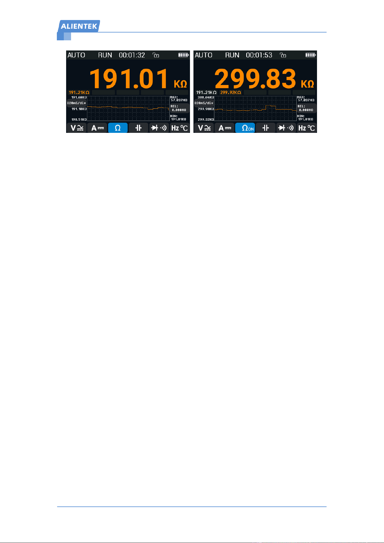
Taking DM40C voltage measurement setting as an example: Click the voltage V
measurement button to enter voltage measurement mode, then Click the MF button to enter the
settings interface (similar for current measurement settings).
Explanation:
DM40C include 5 manual ranges (600mV/6V/60V/600V/1000V) and two automatic ranges
(AUTO and AUTO+). The difference is that AUTO is a fully automatic range, switching
between mV and V ranges automatically, while AUTO+ is a V range automatic range,
only switching within V ranges. AUTO+ mode avoids relay flickering and speeds up
measurement, suitable for frequent high-voltage or DCDC measurements.
Voltage measurement modes include AC, DC, AC+DC (DM40B/C). Select any one to return
to the measurement interface. Clicking MF also returns to the measurement interface. After
returning to the main interface, the range mode is indicated in the top-left corner.
The side AUTO button implements AUTO or AUTO+ function according to the settings.
2.6.2 Resistance Measurement Settings
Taking DM40C resistance measurement setting as an example: Click the resistance Ω
measurement button to enter resistance measurement mode, then click the MF button to enter the
settings interface.
Touchable Multimeter 3-IN-1
用户手册 www.alientek.com
10
DM40 Multimeter User Manual
Explanation:
DM40C resistance measurement ranges include 6 manual ranges (600Ω/6KΩ/60KΩ/600K
Ω/6MΩ/60MΩ) and one automatic range (AUTO). Select any one or click MF to return to the
measurement interface. After returning to the main interface, the range mode is indicated in the
top-left corner.
Resistance measurement include offline and online measurements. Offline mode is measuring
the resistor separately after removing it, featuring high measurement voltage, fast speed, and high
accuracy. Online mode is directly measure on the circuit board, featuring lower voltage, moderate
speed, but small deviation. Select one or click MF to return to the measurement interface.
Click the resistance measurement button to quickly cycle through offline and online modes.
Online mode is indicated by Ω with subscript ON.
3,Oscilloscope & Signal Generator Usage
Instructions
Please refer to the document: DM40 Oscilloscope & Signal
Generator Manual.pdf
Touchable Multimeter 3-IN-1
用户手册 www.alientek.com
11
DM40 Multimeter User Manual
4,Other Functions
4.1 System Settings
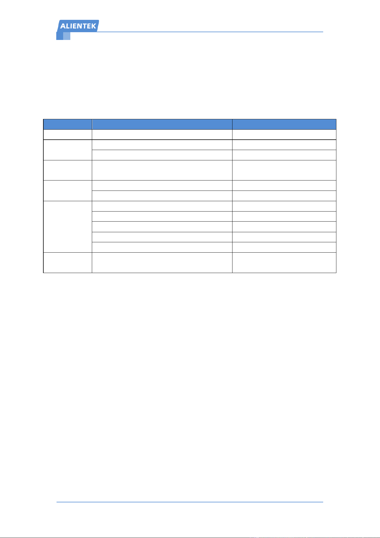
Access system settings by clicking Settings on the main interface.
Table 4.1 System settings
4.2 Firmware Update Instructions
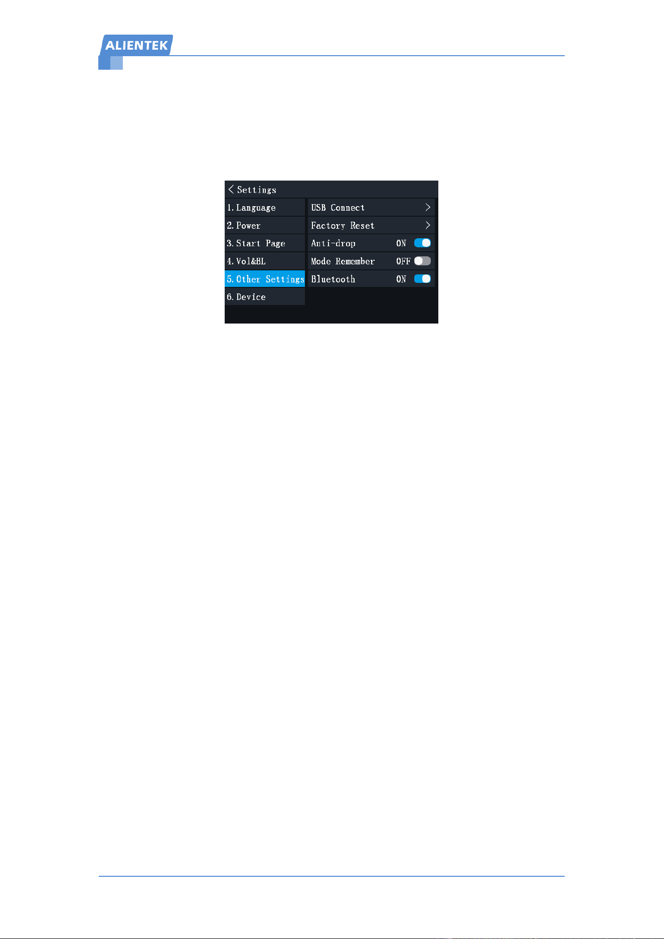
System settings Other Settings, select USB connection, connect DM40 to a computer via
USB cable. The computer will pop up a U-disk. Open the U-disk, place the latest firmware
(dm40xxx.bin), eject the U-disk after transfer is complete. Then long-press the power button to
restart and update the firmware automatically.
4.3 Custom Boot Logo
Create a boot logo with requirements: 480*320 resolution, JPG or BMP format, named
logo.jpg or logo.bmp. Connect the device to a computer, open the U-disk, replace the existing
logo.bmp file, and restart to apply. To remove the boot logo, delete the file directly.
4.4 Quick screenshot instructions
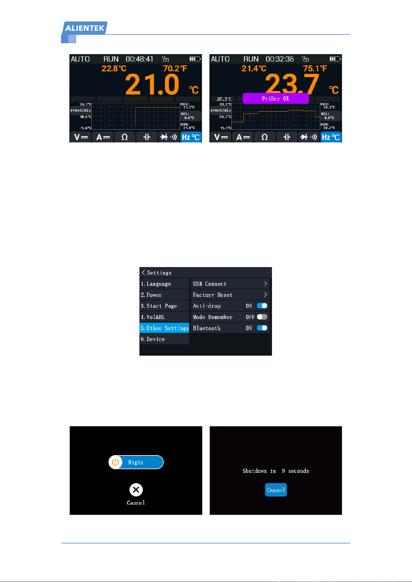
Swipe down with 3 points and hear a beep~ prompt to start taking screenshots. The
multimeter interface has anti aliasing effect and saves for a long time (4~5s). After completing the
screenshot, it will prompt that the screenshot is successful (the saved image can be copied and
viewed by connecting to a computer via USB).
Item
Content
Description
1.Language
Simplified、Traditional、English
Currently supports 3 languages
2. Power
manage
Screen Dim Time :5min、10min、30min、Never
Screen dims to minimum brightness
Shutdown Time :10min、30min、1h、Never
Auto-shutdown at shutdown time
3.Startup page
Multimeter, Oscilloscope,
Signal Generator, Main Interface
Quickly enter the set startup interface
4. Volume and
Backlight
Backlight :10%~100%
Minimum brightness :10%
Volume :0%~100%
0% turns off buzzer
5. Other
Settings
USB Connection
Firmware update and image upload
Factory Reset
Restores to default settings
Shockproof Mode
Avoid error measurement
Mode Remember
DMM measure mode remember
Bluetooth
Enable or disable Bluetooth function
6.Device info
Manufacturer, Website, Model, Serial Number,
Software and Hardware Version
Touchable Multimeter 3-IN-1
用户手册 www.alientek.com
12
DM40 Multimeter User Manual
4.5 Anti-drop Mode Instructions
mV voltage measurement, resistance measurement, diode and continuity measurement, etc.,
require magnetic latching relays. Advantages of magnetic latching relays is low power
consumption. The disadvantages are high cost, lack of drop resistance, and strong shaking that
may cause erroneous measurements, especially for diode and on-off measurements.
Enabling anti-drop mode keeps the relay engaged continuously, effectively avoiding false
measurements caused by ordinary collisions. However, it increases power consumption, reducing
endurance by about 1 hour. If the device is used in a fixed position without movement, it is
recommended to disable shockproof mode for an average endurance of around 12 hours.
4.6 Slide to Shutdown and Auto-shutdown Instructions
Slide two fingers down to prompt slide to shutdown. Cancel or slide to the right to shut down.
If no touch operations are performed within the auto-shutdown time, a 10s countdown with buzzer
prompt will start. No operation will result in auto-shutdown.
Touchable Multimeter 3-IN-1
用户手册 www.alientek.com
13
DM40 Multimeter User Manual
4.7 Mode Memory Functions
System settingOthers,enable mode memory function will remember the last measurement
mode and automatically switch to it after restarting. Users can choose whether to enable this
function based on actual needs.
4.8 Bluetooth Function
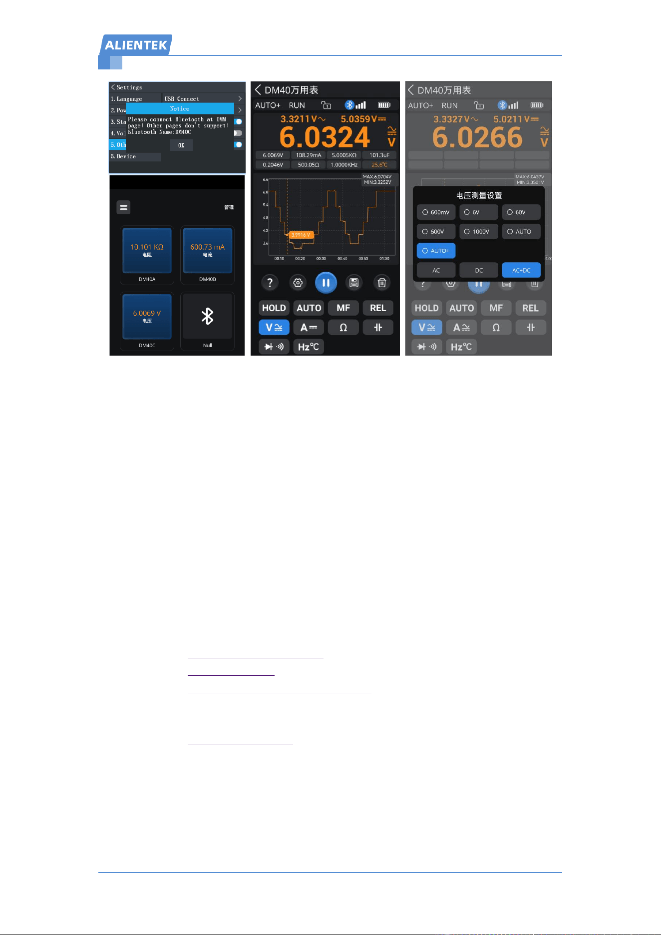
① Install APP: atk-xtool , IOS app, please download from the App Store.
② DM40 Setup: Go to Settings Other Settings, turn on the Bluetooth, Pop up prompt
precautions and Bluetooth name (wait a few seconds for configuration if first use). Then exit the
settings and return to the multimeter measurement interface.
③ Enable Bluetooth on your phone and open the atk-xtool app. The app supports up to 4 devices
(lag may occur if multi-device connection). Click any one to enter, and the app will automatically
scan for nearby devices. Select the device starting with "DM40" (default Bluetooth name is the
same as the model). After successful connection, the measured values will be previewed. Click to
enter the full-featured interface. Once connected, a Bluetooth icon will appear in the status bar of
the DM40 If no device starting with "DM40" is found, restore to the factory settings and repeat
this step.
④ The buttons at the bottom of the app interface have the same functions as the DM40 touch
buttons. The circled Bluetooth icon in the status bar is used for quick Bluetooth connection and
disconnection. For further clarification, click the "?" icon to view instructions.
⑤ The Bluetooth name can be partially modified, supporting up to 10 characters. The first 5
characters represent the device model and cannot be changed.
Touchable Multimeter 3-IN-1
用户手册 www.alientek.com
14
DM40 Multimeter User Manual
5,Services
1. After – sales Service:
We warrant that the product will be free from defects in materials and workmanship
for a period of 1 years from the date of purchase of the product by the original
purchaser from our company. This warranty only applies to the original purchaser
and is not transferable to a third party.
If the product proves defective during the warranty period, we will either repair
the defective product without charge for parts and labour, or will provide a
replacement in exchange for the defective product.
This warranty shall not apply to any defect, failure or damage caused by improper
use or improper or inadequate maintenance and care.
2. Website
Download : www.alientek.com/download
Company : www.alientek.com
Aliexpress : www.aliexpress.com/store/1102909571
3. Contact US
E-mail : fae-smt@alientek.com
FCC Caution:
This device complies with part 15 of the FCC Rules. Operation is subject to the
following two conditions: (1) This device may not cause harmful interference, and (2)
this device must accept any interference received, including interference that may
cause undesired operation.

Touchable Multimeter 3-IN-1
用户手册 www.alientek.com
15
DM40 Multimeter User Manual
Any Changes or modifications not expressly approved by the party responsible for
compliance could void the user's authority to operate the equipment.
Note: This equipment has been tested and found to comply with the limits for a Class
B digital device, pursuant to part 15 of the FCC Rules. These limits are designed to
provide reasonable protection against harmful interference in a residential installation.
This equipment generates uses and can radiate radio frequency energy and, if not
installed and used in accordance with the instructions, may cause harmful interference
to radio communications. However, there is no guarantee that interference will not
occur in a particular installation. If this equipment does cause harmful interference to
radio or television reception, which can be determined by turning the equipment off
and on, the user is encouraged to try to correct the interference by one or more of the
following measures:
-Reorient or relocate the receiving antenna.
-Increase the separation between the equipment and receiver.
-Connect the equipment into an outlet on a circuit different from that to which the
receiver is connected.
-Consult the dealer or an experienced radio/TV technician for help.
The device has been evaluated to meet general RF exposure requirement. The device
can be used in portable exposure condition without restriction.