
Note: Please read this user manual carefully before installation and use!
DG310
Smart Gateway
User Manual
DHMS (Hong Kong) Intelligent Technology Limited
Important Notes:
1. The product is strictly prohibited from being installed in environments containing
flammable or explosive gases.
2. It is strictly forbidden to operate the smart gateway with wet hands.
3. To avoid dangerous accidents, the installation and fixation of the product must be
carried out in strict accordance with the user manual.
4. After unpacking, check the product for damage and verify the quantity and
completeness of all items.
5. Antenna Professional Installation:To ensure optimal performance and operational
safety, it is highly recommended that the high-gain antenna for this product be
installed and adjustedby qualified personnel. Precise calibration of the antenna's
placement, azimuth (direction), and elevation (tilt) is critical for achieving
maximum signal strength and communication stability. Professional installation
mitigates risks such as signal degradation, equipment damage, or potential safety
hazards resulting from improper setup, thereby safeguarding your investment and
ensuring you receive the full benefits of the product. Please contact our technical
support team or an authorized service provider to arrange for professional
installation services.
Note: The products are not sold to the general public but only to distributors.
1 Product Introduction
The DG310 Smart Gateway is a key device in the intelligent operation and maintenance
management system for industrial equipment. It serves as a bridge between wireless
sensors and upper-level systems (such as the DHMS system). It connects to wireless
sensors via Bluetooth, collects data acquired by the sensors, and uploads the data to a host
computer or cloud system.
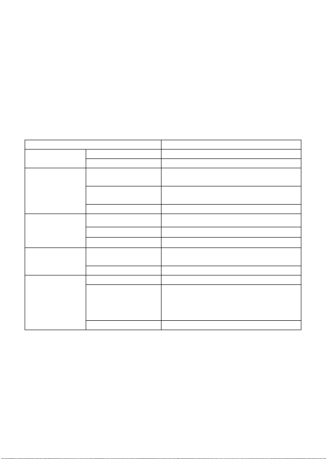
2 Main Technical Parameters
Category
Specification
Power Supply
Operating Voltage
AC 100 to 240 V
Power
4 W
Communication
Upstream
Communication
WIFI, Ethernet
Downstream
Communication
Bluetooth
Load Capacity
Stable for 60+ sensors
Ambient
Temperature
Acquisition
Measurement Range
-20℃ to +80 ℃
Resolution
0.1 ℃
Accuracy
±2 ℃
Operating
Environment
Ambient
Temperature
-20℃ to +80 ℃
Relative Humidity
5%–90% RH. No condensation
Housing
Protection Class
IP65
Dimensions
198 mm × 210 mm × 70 mm (excluding
antenna)
302 mm × 210 mm × 70 mm (including
upward antenna)
Installation Method
Wall-mounted
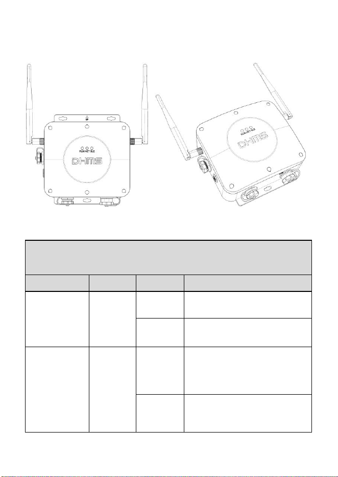
3 Product Appearance
Front view Perspective view
The function definitions of the indicator lights
(as shown in the figure above).
Function
Silk Print
Status
Description
Operating
status
indication
RUN
Always on
After power - on activation, the
indicator light is always on.
Always off
In the inactive state, the indicator
light is always off.
Network status
indication
NET
Always on
In the powered - on state, after two
flashes when the network is
normally connected, the light is
always on when the connection
with the server is normal.
Always off
In the inactive or network -
disconnected state, the indicator
light is always off.
Bluetooth status
indication
BLE
Always on
In the powered - on state, when
connected to the mobile phone
Bluetooth, the indicator light
remains always on.
Flashing
When the sensor has data
transmission, the indicator light
flashes.
4 Installation and Operation
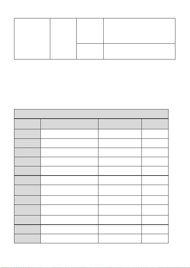
4.1 Unpacking Inspection
The list of gateway accessories is as follows
List of Accessories
Serial
Number
Name
Remarks
Quantity
1
Main Unit
-
1 piece
2
Fixed Back Plate
-
1 piece
3
Inner Hexagon Screws
-
4 pieces
4
Expansion Bolts
-
5 pieces
5
Positioning Stickers
-
1 sheet
6
Hexagon Wrench
6 mm
1 piece
7
Antennas
Two 2.4G antennas
2 pieces
8
Power Connector
-
1 piece
9
Network Port Protection
Connector
-
1 piece
10
Certificate of Conformity
-
1 piece
11
Instruction Manual
-
1 piece
12
Quick Installation Guide
-
1 piece
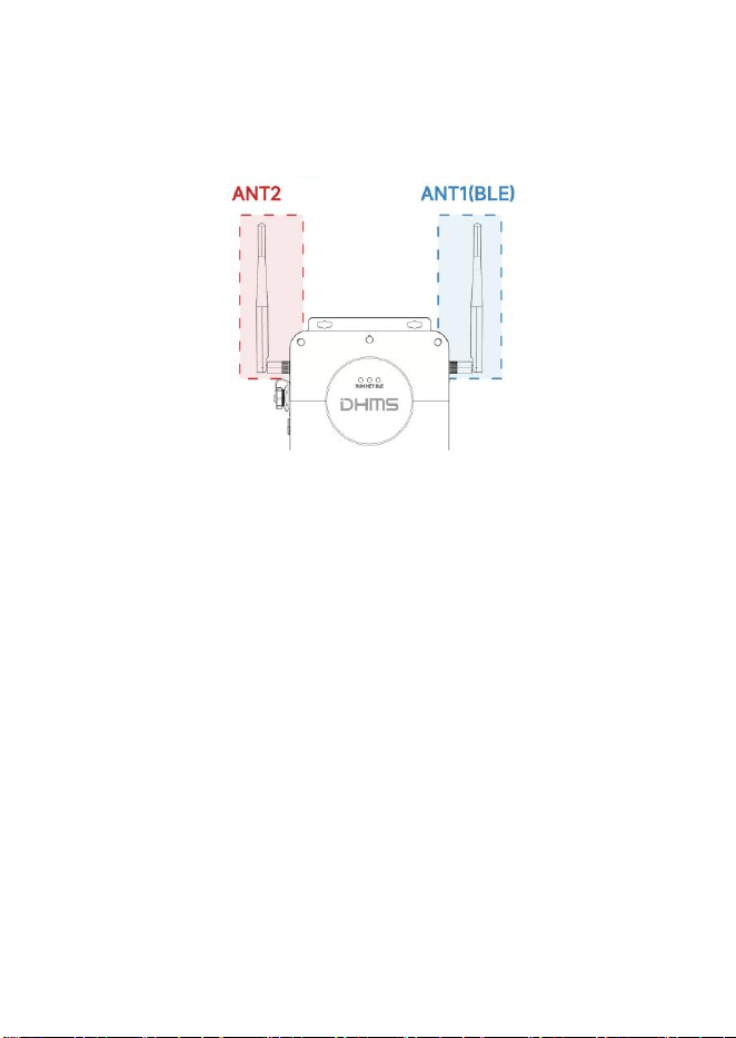
4.2 Antenna Assembly
Install the 2.4G WiFi antenna on ANT2 on the left side of the gateway, and install
the 2.4G antenna on ANT1 (BLE) on the right side of the gateway, as shown in the figure
below.
4.3 Selection of Gateway Installation Location
Read the following installation precautions and select a suitable on-site installation
location.
4.3.1 There is a stable network supply condition on site (e.g., there is a wired Ethernet
network supply condition or 2.4G WiFi signal);
4.3.2 Install in a location where AC power can be easily routed;
4.3.3 The distance between the gateway and the monitored device is within 100 meters;
4.3.4 It is recommended that the installation height of the gateway be higher than that of
the device's monitoring point, and there should be no obstacles between the gateway and
the monitoring point to facilitate signal transmission.
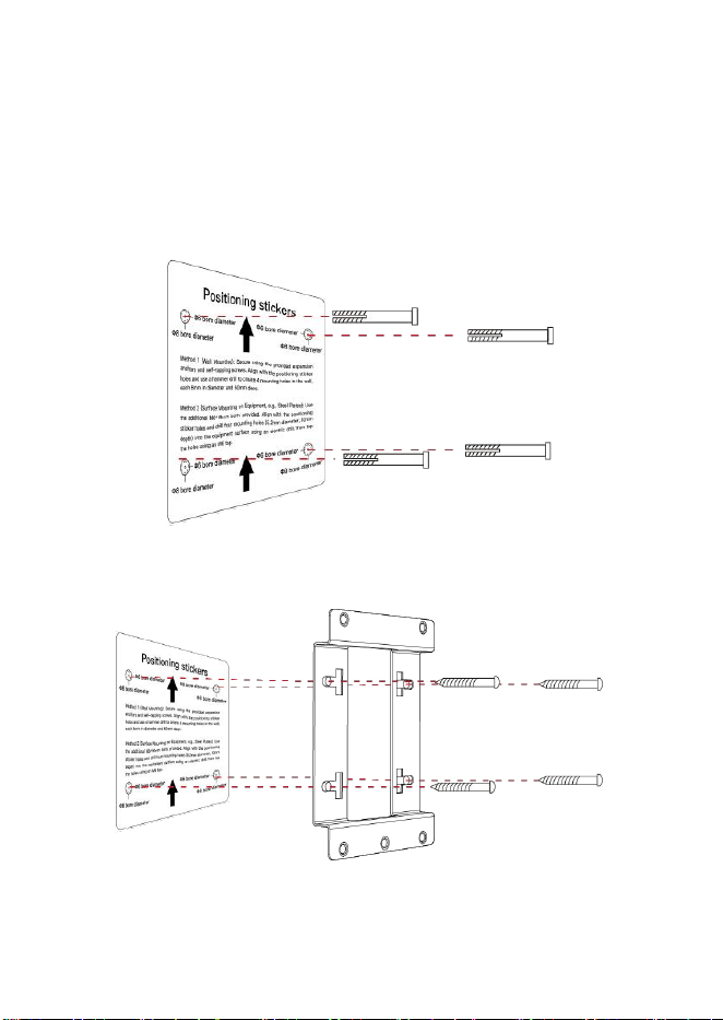
4.4 Wall-mounted Installation of the Gateway
4.4.1 Stick the positioning sticker on the selected wall, use an impact drill to drill four
holes with a diameter of 8 mm and a depth of 60 mm on the wall (according to the hole
opening indication position on the positioning sticker), and put the plastic expansion
tubes into the holes, as shown in the figure below.
4.4.2 Fix the mounting bracket to the wall with 4 self-tapping screws, as shown in the
figure below.
4.4.3 Fix the gateway to the bracket with an "L-shaped hex wrench (6 mm)" and "3 M8
screws".
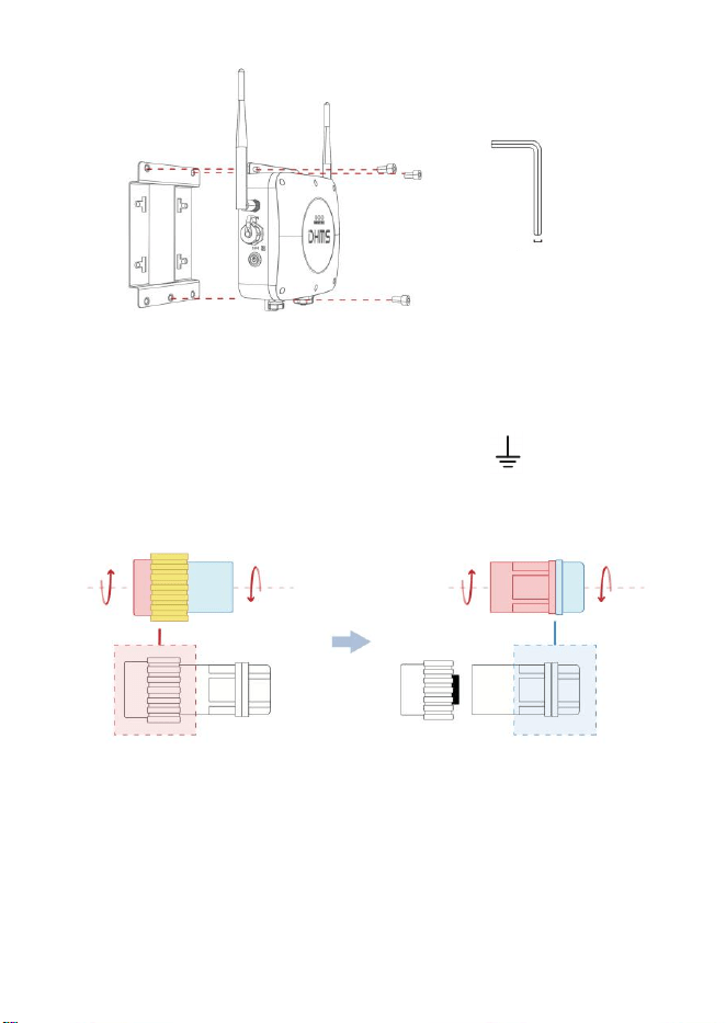
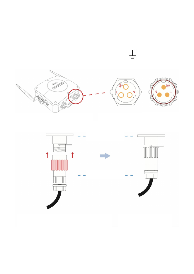
4.5 Power Connection
4.5.1 Unscrew the power connector in the accessories, and use a Phillips screwdriver to
connect the N (neutral wire), L (live wire), and E (ground wire) of the power cord
according to the identification specifications, as shown in the figure below.
6mm
L-shaped hex wrench
Use your left hand to hold the red - marked module in the picture and screw it,
and use your right hand to hold the blue-marked module and screw it
respectively.
Note: Do not screw the yellow-marked module.
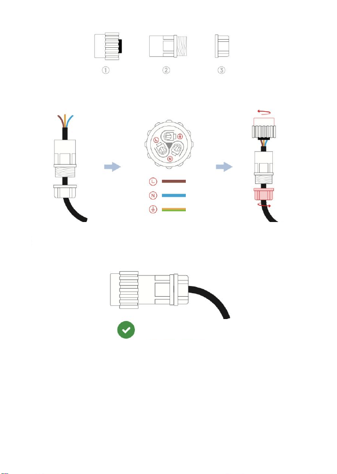
Note 1: Non-professional electricians are strictly prohibited from operating. The
entire power wiring process must be carried out under power-off condition.
Disassemble the power supply parts of the connector
according to the diagram above.
Slide parts ② and ③
onto the power cable
as shown in the
diagram.
Invert part ① and
connect the electric
wires as shown in the
diagram.
Screw parts ① , ② ,
and ③ to assemble
them.
The electric wiring is completed.
Note 2: Under normal circumstances, the N (neutral wire) is blue or green, the L
(live wire) is brown or red, and the E (ground wire) is yellow-green striped.
4.5.2 Tighten the properly wired power connector and plug it into the power interface of
the gateway (note that the wire sequence of L, N, and ground between the power
connector and the power interface must be consistent).
Align the interfaces on both sides according
to the consistent wiring sequence, insert and
screw the red-marked module in the figure
on tightly.
The electric wiring is
completed.
The word "POWER" indicates the
power interface of the gateway.
Power interface of
the gateway.
Power connector.
Power connector
Power interface
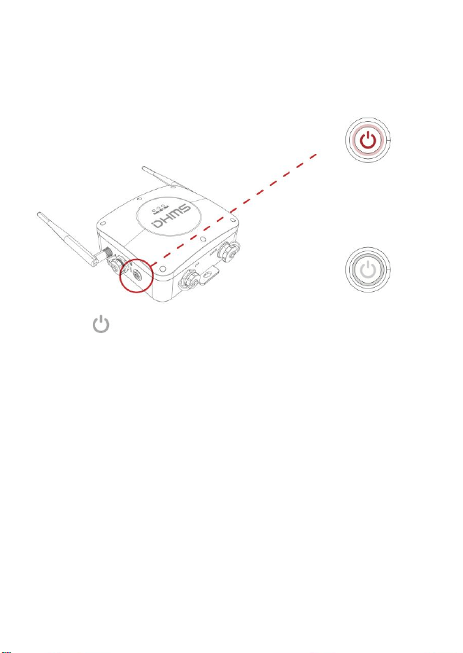
4.5.3 After power is on, press the power switch on the left to check whether the power
supply is normal (if normal, the switch indicator will be always on). After the check, turn
off the power (keep the power switch indicator in the off state).
4.6 Network Access
Network access is divided into two ways: accessing wireless network (4G cellular
network) and accessing wired network.
4.6.1 Method 1: Access Wireless Network
If connecting to a WiFi network, there is no need to perform any operation in this step.
Simply follow the guidance in the next step "Add Gateway in App" to complete the
configuration.
4.6.2 Method 2: Access Wired Network
The power switch of the
gateway is located here.
When pressed, the power
switch will look as shown
in the diagram. If the light
stays on, the power
supply is normal.
The power indicator light
is off.
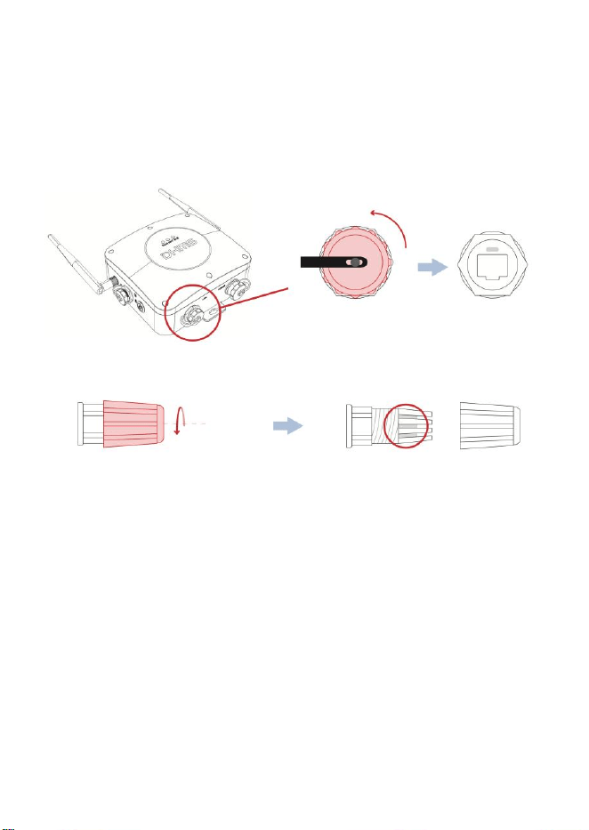
The DG310 gateway can be connected via wired Ethernet (ensure that the on-site network
communication is normal). The specific connection steps are as shown in the figure
below.
The word "LAN" indicates the
Ethernet port of the gateway.
Unscrew the top covercounterclockwise
to expose the Ethernet port.
Screw the red-marked module
of the protective joint of the
network port.
Remove the C-shaped retaining
ring.
Note: If waterproof and dustproof functions are not required, the network port
protective connector is not necessary for the network port, and the network cable
can be directly connected.
4.7 Add Gateway via App
Open the "DHMSCare Intelligent App" to enter the homepage, select "Add Gateway" on
the guide page, and follow the App prompts to complete the gateway addition.
5 Judgment of Signal Strength at the Gateway Installation
Location
The WiFi signal strength reported by the gateway can be queried via the mobile App to
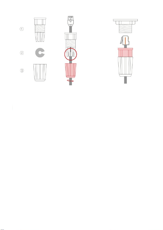
Siide parts ①, ② , and ③ onto the network
cable as shown in the figure, and screw the red
- marked module on tightly.
Note that the C-shaped retaining ring must be
reinstalled; otherwise, the protective function
will be compromised.
Insert the Ethernet cable
connector in the correct
orientation, screw the red -
marked module on tightly, and
complete the electric wiring.
determine the quality of the WiFi signal at the installation location.
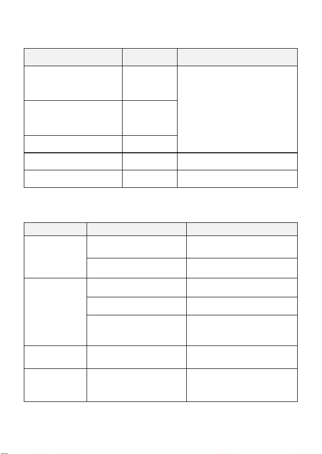
Signal Strength (RSSI Value)
Judgment
Solutions
RSSI < -90
Extremely poor
1. Change the installation location of the
gateway.
2. Adjust the direction of the gateway
antenna.
-90 ≤ RSSI ≤ -80
Poor
-80 ≤ RSSI ≤ -70
Average
-70 ≤ RSSI ≤ -60
Good
-60 ≤ RSSI
Excellent
6 Troubleshooting and Resolution
Phenomenon
Possible Fault Causes
Solutions
The power switch
is not on.
Incorrect connection of the
aviation plug.
Reconnect the power line as required.
The switch is not turned on.
Press to turn on the switch.
WiFi cannot
connect normally.
The WiFi signal is poor.
Move to a place with a better signal.
Incorrect input of WiFi account
password.
Re - input the correct WiFi account
and password.
The network of the on-site power
supply equipment is
disconnected.
Repair the network of the power
supply equipment.
Ethernet
networking
abnormality
Abnormal Ethernet access.
Check the network cable and
reconnect.
Unable to connect
to the wireless
sensor
Abnormal connection of the
Bluetooth antenna.
Retighten the antenna.

The distance to the wireless
sensor is relatively far, resulting
in weak Bluetooth signal.
Move the gateway to a position closer
to the wireless sensor.
If the above measures cannot solve the problem, please contact the manufacturer or
dealer for solution!
7 Repair and Maintenance
• Product after-sales service must be carried out by the manufacturer or authorized dealers;
• Non-professional maintenance personnel are strictly prohibited from disassembling the
gateway. Unauthorized disassembly of the gateway will lead to the invalidation of the
quality guarantee;
•
The power supply of the gateway must be disconnected before maintenance.
DG310:
2.4G Wi-Fi: 2412~2462 MHz(802.11b/g/n20), 2422~2452 MHz(802.11n40)
BLE(1 Mbps/2 Mpbs): 2402-2480 MHz
Maximum Peak Output Power
2.4G Wi-Fi:
802.11b: 15.815 dBm
802.11g: 19.326 dBm
802.11n20: 18.044 dBm
802.11n40: 18.39 dBm
BLE(1 Mbps): 9.93 dBm
BLE(2 Mbps): 9.90 dBm
FCC Statement
Any Changes or modifications not expressly approved by the party responsible for
compliance could void the user’s authority to operate the equipment.
This device complies with part 15 of the FCC Rules. Operation is subject to the following
two conditions:
(1) This device may not cause harmful interference, and
(2) This device must accept any interference received, including interference that may
cause undesired operation.
This equipment complies with FCC radiation exposure limits set forth for an uncontrolled
environment. This equipment should be installed and operated with minimum distance
20cm between the radiator& your body.
FCC Radiation Exposure Statement:
This equipment complies with FCC radiation exposure limits set forth for an uncontrolled
environment. This equipment should be installed and operated with minimum distance 20cm
between the radiator& your body.
Note : This equipment has been tested and found to comply with the limits for a Class B
digital device, pursuant to part 15 of the FCC Rules. These limits are designed to provide
reasonable protection against harmful interference in a residential installation. This equipment
generates,uses and can radiate radio frequency energy and, if not installed and used in
accordance with the instructions, may cause harmful interference to radio communications.
However, there is no guarantee that interference will not occur in a particular installation. If
this equipment does cause harmful interference to radio or television reception, which can be
determined by turning the equipment off and on, the user is encouraged to try to correct the
interference by one or more of the following measures:
—Reorient or relocate the receiving antenna.
—Increase the separation between the equipment and receiver.
—Connect the equipment into an outlet on a circuit different from that to which the receiver is
connected.
—Consult the dealer or an experienced radio/TV technician for help.
19H Maxgrand Plaza, No.3 Tai Yau Street, San Po Kong, Kowloon, Hong Kong SAR, China
Contact Number: 0852-6213-9846