VERSION 1.6, MIN. HW 1.5
Technical Drawings
Technische Zeichnungen
D2100E
VIDEO
TUTORIALS
Visit our website for
video tutorials!
2
1
1
2
2
3
3
4
4
5
5
6
6
A A
B B
C C
D D
Page
1
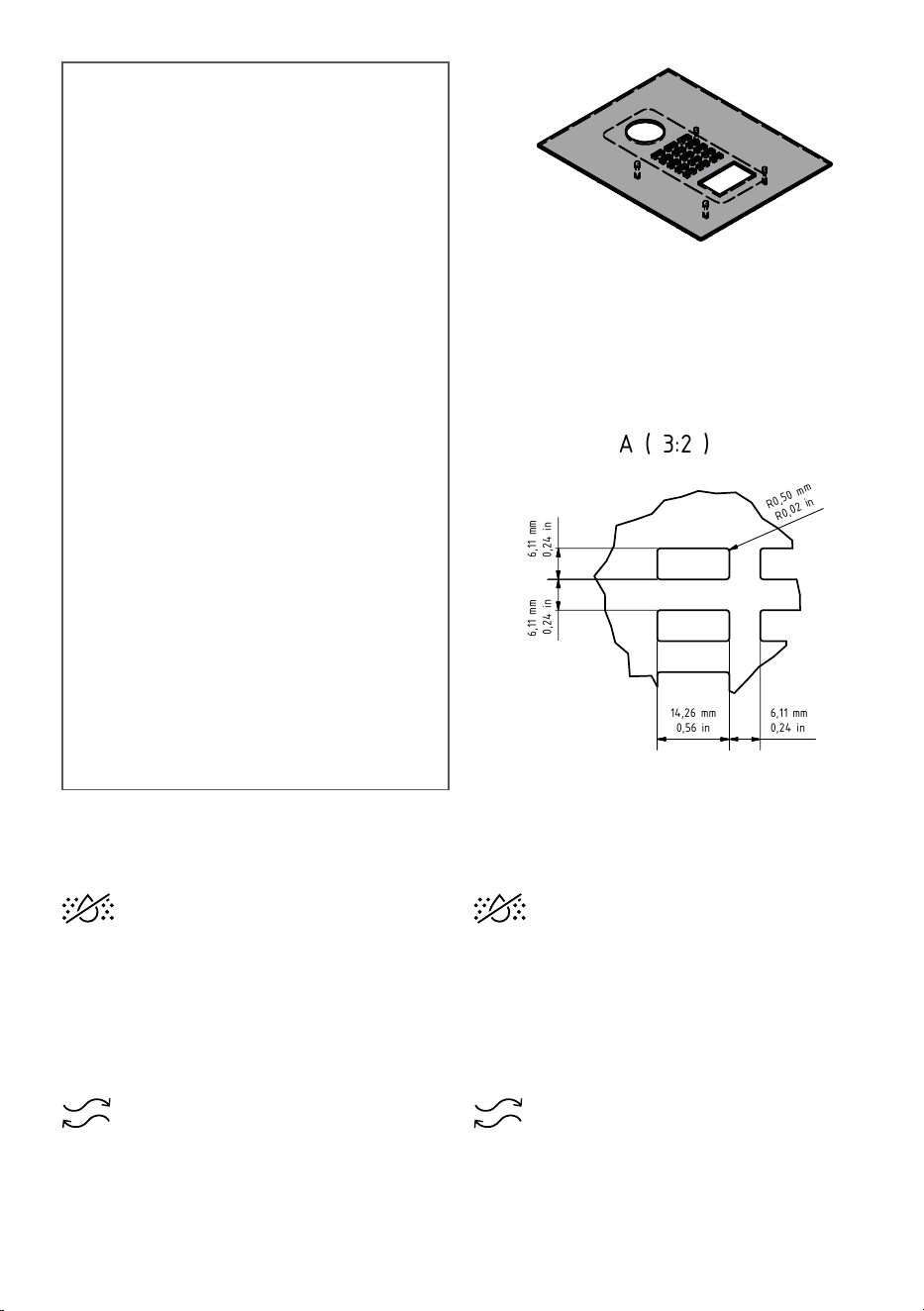
EN: Assembly instructions and illustrations
- Front panel must be exactly 3mm thick.
- The DoorBird main electrical unit must be pressed flat against the front panel. A gasket is attached to the main electrical unit by us.
- Underneath the main electrical unit, there must be enough space planned for the Phoenix and CAT cabling (D21x: approx. 5 cm/1,97 in).
- In order to ensure problem-free installat
ion, a free area of at least 5 mm/0,2 in around each module.
DE: Montagehinweise und -zeichnungen
- Frontplatte muss genau 3mm stark sein.
- Die elektrische Haupteinheit des DoorBirds muss fl
ächig an die Frontplatte aufgepresst werden. Eine Dichtung ist von uns an der elektrischen Haupteinheit angebracht.
- Unterhalb der elektrischen Haupteinheit muss ausreichend Platz für die Phoenix- und CAT-Verkabelung eingeplant werden (D21x: ca. 5 cm/1,97 in).
- Um eine problemlose Montage gewährleisten zu können, sollte eine Freifläche von mindestens 5 mm/0,2 in um jedes Modul eingeplant werden.
DoorBird D2100E
Page/Seite 2
D21x Call Button / D21x Ruftaste
Page/Seite 3
Keypad Module with 16 keys /
Keypad Modul mit 16 Tasten
Page/Seite 4
Keypad Module with 12 keys /
Keypad Modul mit 12 Tasten
Page/Seite 5
Display-/Info Panel Module /
Display-/ Infopanel Modul
Page/Seite 6
IP Video Door Station
D21x series
EN: ASSEMBLY INSTRUCTIONS AND
ILLUSTRATIONS
- The front panel must be exactly 3.00 mm thick.
- The main electrical unit of the IP video door
station must be pressed flat against the front
panel. A gasket is attached on the main
electrical unit ex works.
- Underneath the main electrical unit, enough
space for the Phoenix and CAT cabling must be
planned for (approx. 5 cm / 1.97 in).
- In order to ensure an easy installation, a free
area around each module should be planned
(approx. 5 mm / 0.2 in).
DE: MONTAGEHINWEISE
UND -ZEICHNUNGEN
- Die Frontplatte muss genau 3,00 mm stark sein.
- Die elektrische Haupteinheit der IP-Video-
Türstation muss flächig an die Frontplatte
aufgepresst werden. Eine Dichtung ist ab Werk
an der elektrischen Haupteinheit angebracht.
- Unterhalb der elektrischen Haupteinheit muss
ausreichend Platz für die Phoenix- und CAT-
Verkabelung eingeplant werden
(ca. 5 cm / 1.97 in).
- Um eine problemlose Montage gewährleisten
zu können, sollte eine Freifläche um jedes
Modul eingeplant werden (ca. 5 mm / 0.2 in).
A ( 3:2 )
A
1
1
2
2
3
3
4
4
5
5
6
6
A A
B B
C C
D D
Page
2
Format
A3
Scale
1:2
Drawn by
Checked by
Haraldsson Date
Schmidt Date
12.12.2019
12.12.2019
Bird Home Automation GmbH
Joachimsthaler Straße 12
D-10719 Berlin
Germany
Assembly instructions and illustrations
Montagehinweise und -zeichnungen
D2100E
Material: stainless steel / rostfreier Edelstahl
V2A (1.4301); V4A (1.4404)
For technical support only /
Nur für den technischen Support
4
2,
00
m
m
1
,
6
5
i
n
5
4
,
9
9
m
m
2
,
1
7
in
1
7
,
0
0
m
m
0
,
6
7
in
3
3
,
0
0
m
m
1
,
3
0
in
3
6
,
7
5
m
m
1
,
4
5
in
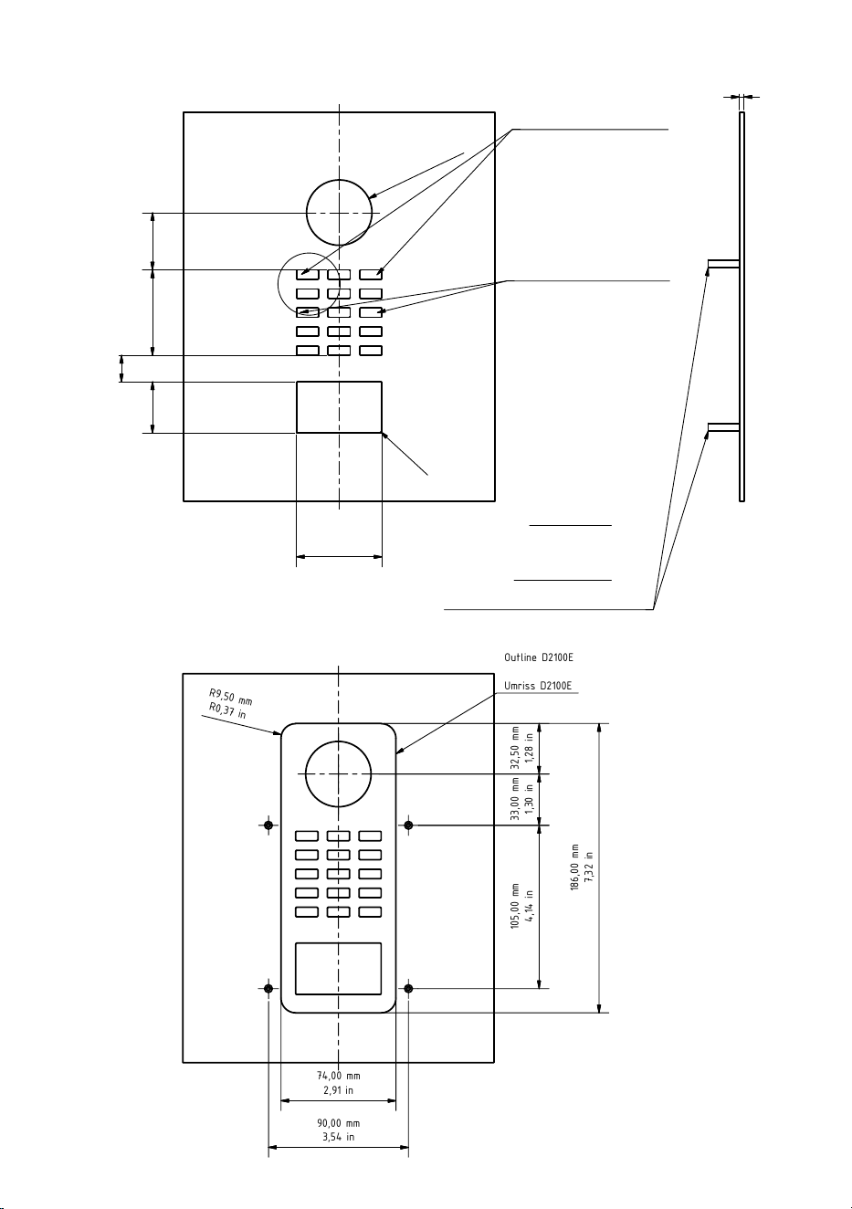
Mounting threads
4x M3x20 female threaded bushing
15 mm (0,59 in) thread length
Befestigungsgewinde
4x M3x20 Innengewindebuchse
15 mm (0,59 in) Gewindelänge
Outline D2100E
Umriss D2100E
74,00 mm
2,91 in
1
8
6
,
0
0
m
m
7
,
3
2
in
R
9
,
5
0
m
m
R
0
,
3
7
i
n
90,00 mm
3,54 in
1
0
5
,
0
0
m
m
4
,
1
4
in
3
3
,
0
0
m
m
1
,
3
0
in
Depth of D2100E:
approx. 43 mm (1,69 in)
Tiefe
des D2100E: ca. 43 mm (1,69 in)
6
,
1
1
m
m
0
,
2
4
in
6
,
1
1
m
m
0
,
2
4
in
R
0
,
50
m
m
R
0,
0
2
i
n
R
0
,
5
0
m
m
R
0
,
0
2
i
n
3
2
,
5
0
m
m
1
,
2
8
in
Position of light sensor and
microphone
Position des Lichtsensors und
des Mikrofons
Position of the black mounting
screws of the D2100E
Position der schwarzen Befesti-
gungsschrauben des D2100E
3,00 mm
0,12 in
14,26 mm
0,56 in
6,11 mm
0,24 in
55,00 mm
2,17 in
DE: Wichtiger Hinweis zur Hohlraummontage
(z.B. in Stelen und Briefkästen):
Zum Schutz der elektronischen Einheiten sorgen
Sie bitte für die Absicherung der technischen
Komponenten vor Tropf- und Laufwasser, das durch
Kondensat entsteht oder durch Öffnungen in den
Montageraum eindringt. Weiter ist berücksichtigen,
dass es zum Schutz der elektronischen Einheiten
innerhalb des Montageraums nicht zu einer Staunässe
kommen darf.
Es ist für ausreichende Luftzirkulation zu sorgen und
den ungehinderten Abfluss von Wasser am Fuß der
Installation.
Bei Nichtberücksichtigung wird eine Gewährleistung
abgelehnt.
EN: Important note for cavity mounting (e.g. in
pedestals and mailboxes):
To protect the electronic units, please ensure that the
technical components are protected against dripping
and running water caused by condensate or entering
the mounting space through openings. To protect
the electronic units, ensure that the mounting space
inside is not accumulating water.
Sucient air circulation must be ensured, as well as
unobstructed drainage of water at the base of the
installation.
Failure to do so will result in warranty being declined.
3
A ( 3:2 )
A
1
1
2
2
3
3
4
4
5
5
6
6
A A
B B
C C
D D
Page
2
Format
A3
Scale
1:2
Drawn by
Checked by
Haraldsson Date
Schmidt Date
12.12.2019
12.12.2019
Bird Home Automation GmbH
Joachimsthaler Straße 12
D-10719 Berlin
Germany
Assembly instructions and illustrations
Montagehinweise und -zeichnungen
D2100E
Material: stainless steel / rostfreier Edelstahl
V2A (1.4301); V4A (1.4404)
For technical support only /
Nur für den technischen Support
4
2,
00
m
m
1
,
6
5
i
n
5
4
,
9
9
m
m
2
,
1
7
in
1
7
,
0
0
m
m
0
,
6
7
in
3
3
,
0
0
m
m
1
,
3
0
in
3
6
,
7
5
m
m
1
,
4
5
in
Mounting threads
4x M3x20 female threaded bushing
15 mm (0,59 in) thread length
Befestigungsgewinde
4x M3x20 Innengewindebuchse
15 mm (0,59 in) Gewindelänge
Outline D2100E
Umriss D2100E
74,00 mm
2,91 in
1
8
6
,
0
0
m
m
7
,
3
2
in
R
9
,
5
0
m
m
R
0
,
3
7
i
n
90,00 mm
3,54 in
1
0
5
,
0
0
m
m
4
,
1
4
in
3
3
,
0
0
m
m
1
,
3
0
in
Depth of D2100E:
approx. 43 mm (1,69 in)
Tiefe des D2100E: ca. 43 mm (1,69 in)
6
,
1
1
m
m
0
,
2
4
in
6
,
1
1
m
m
0
,
2
4
in
R
0
,
50
m
m
R
0,
0
2
i
n
R
0
,
5
0
m
m
R
0
,
0
2
i
n
3
2
,
5
0
m
m
1
,
2
8
in
Position of light sensor and
microphone
Position des Lichtsensors und
des Mikrofons
Position of the black mounting
screws of the D2100E
Position der schwarzen Befesti-
gungsschrauben des D2100E
3,00 mm
0,12 in
14,26 mm
0,56 in
6,11 mm
0,24 in
55,00 mm
2,17 in
A ( 3:2 )
A
1
1
2
2
3
3
4
4
5
5
6
6
A A
B B
C C
D D
Page
2
Format
A3
Scale
1:2
Drawn by
Checked by
Haraldsson Date
Schmidt Date
12.12.2019
12.12.2019
Bird Home Automation GmbH
Joachimsthaler Straße 12
D-10719 Berlin
Germany
Assembly instructions and illustrations
Montagehinweise und -zeichnungen
D2100E
Material: stainless steel / rostfreier Edelstahl
V2A (1.4301); V4A (1.4404)
For technical support only /
Nur für den technischen Support
4
2,
00
m
m
1
,
6
5
i
n
5
4
,
9
9
m
m
2
,
1
7
in
1
7
,
0
0
m
m
0
,
6
7
in
3
3
,
0
0
m
m
1
,
3
0
in
3
6
,
7
5
m
m
1
,
4
5
in
Mounting threads
4x M3x20 female threaded bushing
15 mm (0,59 in) thread length
Befestigungsgewinde
4x M3x20 Innengewindebuchse
15 mm (0,59 in) Gewindelänge
Outline D2100E
Umriss D2100E
74,00 mm
2,91 in
1
8
6
,
0
0
m
m
7
,
3
2
in
R
9
,
5
0
m
m
R
0
,
3
7
i
n
90,00 mm
3,54 in
1
0
5
,
0
0
m
m
4
,
1
4
in
3
3
,
0
0
m
m
1
,
3
0
in
Depth of D2100E:
approx. 43 mm (1,69 in)
Tiefe des D2100E: ca. 43 mm (1,69 in)
6
,
1
1
m
m
0
,
2
4
in
6
,
1
1
m
m
0
,
2
4
in
R
0
,
50
m
m
R
0,
0
2
i
n
R
0
,
5
0
m
m
R
0
,
0
2
i
n
3
2
,
5
0
m
m
1
,
2
8
in
Position of light sensor and
microphone
Position des Lichtsensors und
des Mikrofons
Position of the black mounting
screws of the D2100E
Position der schwarzen Befesti-
gungsschrauben des D2100E
3,00 mm
0,12 in
14,26 mm
0,56 in
6,11 mm
0,24 in
55,00 mm
2,17 in
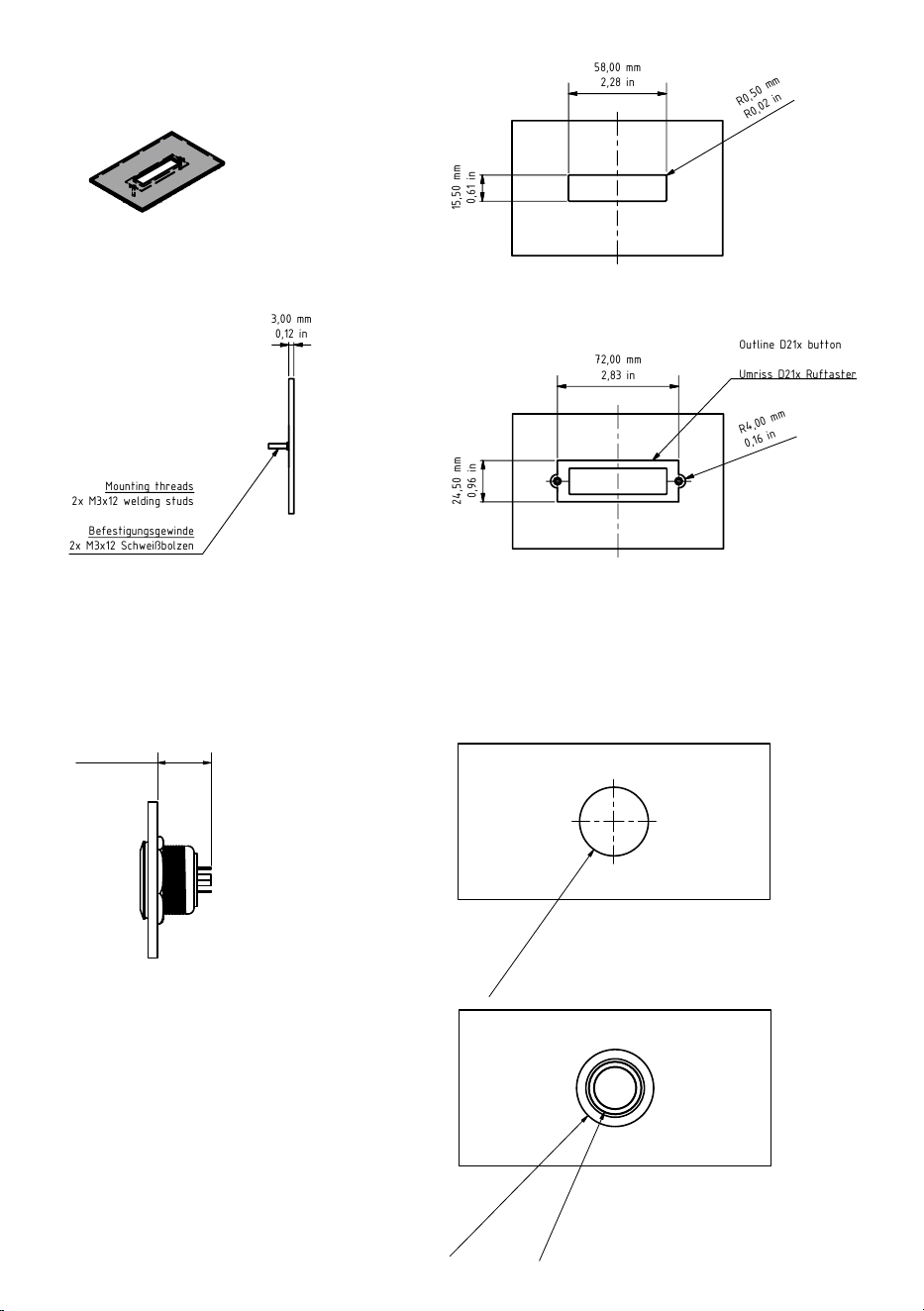
4
1
1
2
2
3
3
4
4
5
5
6
6
A A
B B
C C
D D
Page
3
Format
A3
Scale
1:2
Drawn by
Checked by
Haraldsson Date
Schmidt Date
12.12.2019
12.12.2019
Bird Home Automation GmbH
Joachimsthaler Straße 12
D-10719 Berlin
Germany
Assembly instructions and illustrations
Montagehinweise und -zeichnungen
D21x btn
Material: stainless steel / rostfreier Edelstahl
V2A (1.4301); V4A (1.4404)
For technical support only /
Nur für den technischen Support
58,00 mm
2,28 in
1
5
,
5
0
m
m
0
,
6
1
in
R
0
,
5
0
m
m
R
0
,
0
2
i
n
3,00 mm
0,12 in
72,00 mm
2,83 in
R4
,
0
0
m
m
0
,
1
6
i
n
2
4
,
5
0
m
m
0
,
9
6
in
Outline D21x button
Umriss D21x Ruftaster
Mounting threads
2x M3x12 welding studs
Befestigungsgewinde
2x M3x12 Schweißbolzen
Call Button for DoorBird D21x (NOT for D11x)
Ruftaste für DoorBird D21x (NICHT für D11x)
1
1
2
2
3
3
4
4
5
5
6
6
A A
B B
C C
D D
Page
3
Format
A3
Scale
1:2
Drawn by
Checked by
Haraldsson Date
Schmidt Date
12.12.2019
12.12.2019
Bird Home Automation GmbH
Joachimsthaler Straße 12
D-10719 Berlin
Germany
Assembly instructions and illustrations
Montagehinweise und -zeichnungen
D21x btn
Material: stainless steel / rostfreier Edelstahl
V2A (1.4301); V4A (1.4404)
For technical support only /
Nur für den technischen Support
58,00 mm
2,28 in
1
5
,
5
0
m
m
0
,
6
1
in
R
0
,
5
0
m
m
R
0
,
0
2
i
n
3,00 mm
0,12 in
72,00 mm
2,83 in
R4
,
0
0
m
m
0
,
1
6
i
n
2
4
,
5
0
m
m
0
,
9
6
in
Outline D21x button
Umriss D21x Ruftaster
Mounting threads
2x M3x12 welding studs
Befestigungsgewinde
2x M3x12 Schweißbolzen
Call Button for DoorBird D21x (NOT for D11x)
Ruftaste für DoorBird D21x (NICHT für D11x)
1
1
2
2
3
3
4
4
5
5
6
6
A A
B B
C C
D D
Page
3
Format
A3
Scale
1:2
Drawn by
Checked by
Haraldsson Date
Schmidt Date
12.12.2019
12.12.2019
Bird Home Automation GmbH
Joachimsthaler Straße 12
D-10719 Berlin
Germany
Assembly instructions and illustrations
Montagehinweise und -zeichnungen
D21x btn
Material: stainless steel / rostfreier Edelstahl
V2A (1.4301); V4A (1.4404)
For technical support only /
Nur für den technischen Support
58,00 mm
2,28 in
1
5
,
5
0
m
m
0
,
6
1
in
R
0
,
5
0
m
m
R
0
,
0
2
i
n
3,00 mm
0,12 in
72,00 mm
2,83 in
R4
,
0
0
m
m
0
,
1
6
i
n
2
4
,
5
0
m
m
0
,
9
6
in
Outline D21x button
Umriss D21x Ruftaster
Mounting threads
2x M3x12 welding studs
Befestigungsgewinde
2x M3x12 Schweißbolzen
Call Button for DoorBird D21x (NOT for D11x)
Ruftaste für DoorBird D21x (NICHT für D11x)
1
1
2
2
3
3
4
4
5
5
6
6
A A
B B
C C
D D
Page
1
EN: Assembly instructions and illustrations
- Front panel must be exactly 3mm thick.
- The DoorBird main electrical unit must be pressed flat against the front panel. A gasket is attached to the main electrical unit by us.
- Underneath the main electrical unit, there must be enough space planned for the Phoenix and CAT cabling (D21x: approx. 5 cm/1,97 in).
- In order to ensure problem-free installat
ion, a free area of at least 5 mm/0,2 in around each module.
DE: Montagehinweise und -zeichnungen
- Frontplatte muss genau 3mm stark sein.
- Die elektrische Haupteinheit des DoorBirds muss fl
ächig an die Frontplatte aufgepresst werden. Eine Dichtung ist von uns an der elektrischen Haupteinheit angebracht.
- Unterhalb der elektrischen Haupteinheit muss ausreichend Platz für die Phoenix- und CAT-Verkabelung eingeplant werden (D21x: ca. 5 cm/1,97 in).
- Um eine problemlose Montage gewährleisten zu können, sollte eine Freifläche von mindestens 5 mm/0,2 in um jedes Modul eingeplant werden.
DoorBird D2100E
Page/Seite 2
D21x Call Button / D21x Ruftaste
Page/Seite 3
Keypad Module with 16 keys /
Keypad Modul mit 16 Tasten
Page/Seite 4
Keypad Module with 12 keys /
Keypad Modul mit 12 Tasten
Page/Seite 5
Display-/Info Panel Module /
Display-/ Infopanel Modul
Page/Seite 6
IP Video Door Station
D21x series
1
1
2
2
3
3
4
4
5
5
6
6
A A
B B
C C
D D
Page
1
Format
A3
Drawing number
Stainless steel button
Designation
Stainless steel button
General tolerance
2768 -mK
Scale
Material:
General pinciples
of presentation
ISO 128-1
Bird Home Automation GmbH
Uhlandstr. 165
D-10719 Berlin
Germany
Confidential
2
2
,
0
0
m
m
0
.
8
7
i
n
17,20~ mm
~0.68 in
2
4
,
7
3 m
m
0
.
9
7 i
n
1
6
,
7
2
m
m
0
.
6
6
i
n
1
1
2
2
3
3
4
4
5
5
6
6
A A
B B
C C
D D
Page
1
Format
A3
Drawing number
Stainless steel button
Designation
Stainless steel button
General tolerance
2768 -mK
Scale
Material:
General pinciples
of presentation
ISO 128-1
Bird Home Automation GmbH
Uhlandstr. 165
D-10719 Berlin
Germany
Confidential
2
2
,
0
0
m
m
0
.
8
7
i
n
17,20~ mm
~0.68 in
2
4
,
7
3 m
m
0
.
9
7 i
n
1
6
,
7
2
m
m
0
.
6
6
i
n
1
1
2
2
3
3
4
4
5
5
6
6
A A
B B
C C
D D
Page
1
Format
A3
Drawing number
Stainless steel button
Designation
Stainless steel button
General tolerance
2768 -mK
Scale
Material:
General pinciples
of presentation
ISO 128-1
Bird Home Automation GmbH
Uhlandstr. 165
D-10719 Berlin
Germany
Confidential
2
2
,
0
0
m
m
0
.
8
7
i
n
17,20~ mm
~0.68 in
2
4
,
7
3 m
m
0
.
9
7 i
n
1
6
,
7
2
m
m
0
.
6
6
i
n
D21x Call Button / D21x Ruftaste
Round Stainless steel button / Runde Edelstahlruftaste
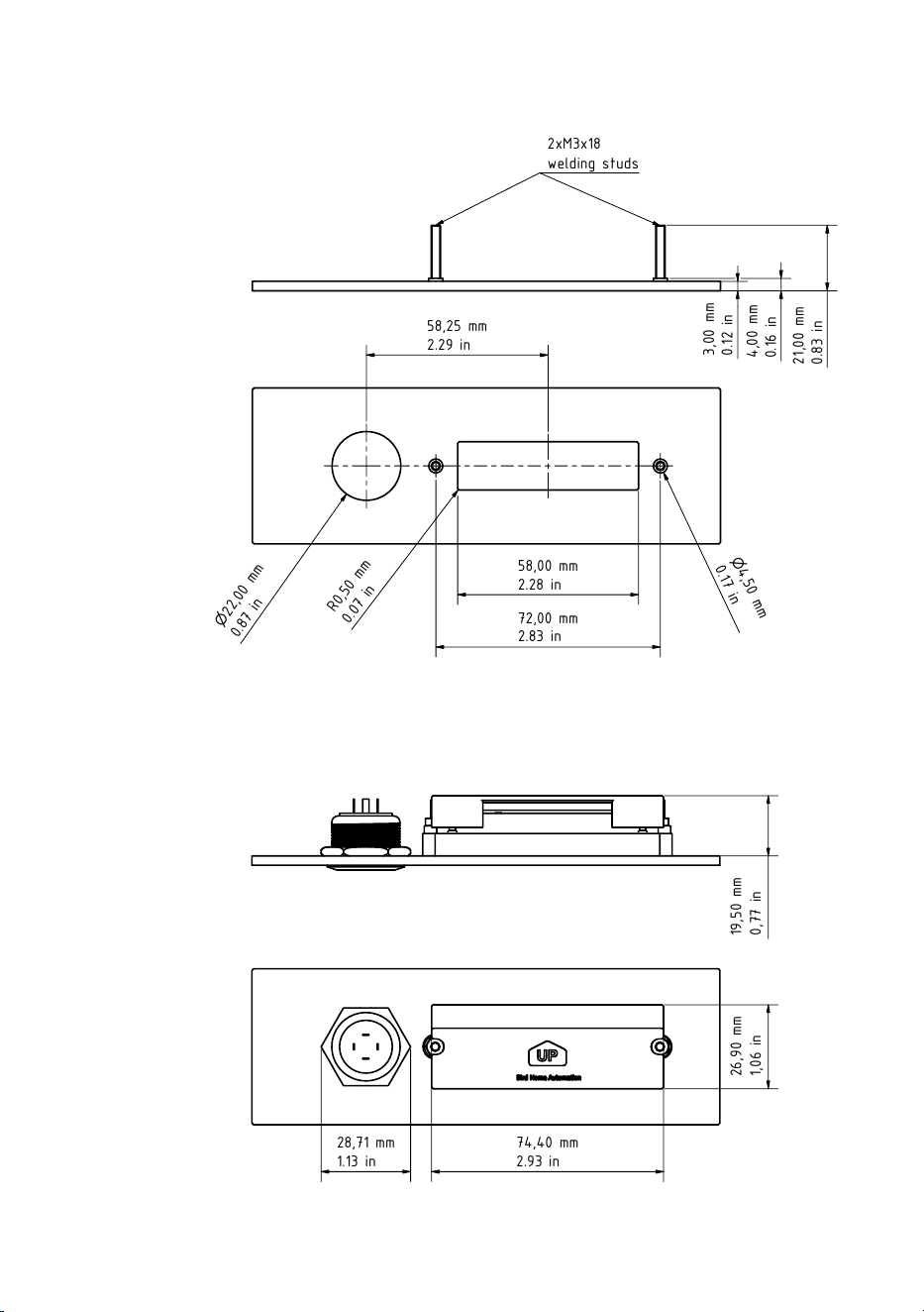
5
1
1
2
2
3
3
4
4
5
5
6
6
A A
B B
C C
D D
Page
1
Format
A3
Drawing number
Round Button with nameplate
Designation
Round button with nameplate
General tolerance
2768 -mK
Scale
Material:
General pinciples
of presentation
ISO 128-1
Bird Home Automation GmbH
Uhlandstr. 165
D-10719 Berlin
Germany
Confidential
72,00 mm
2.83 in
2
2
,
0
0
m
m
0
.
8
7
i
n
58,25 mm
2.29 in
58,00 mm
2.28 in
4
,
5
0
m
m
0
.
1
7
i
n
R
0
,
5
0
m
m
0
.
0
7
i
n
2
1
,
0
0
m
m
0
.8
3
in
3
,
0
0
m
m
0
.1
2
in
4
,
0
0
m
m
0
.1
6
in
1
9
,
5
0
m
m
0
,
7
7
in
2xM3x18
welding studs
2
6
,
9
0
m
m
1
,
0
6
in
74,40 mm
2.93 in
28,71 mm
1.13 in
1
1
2
2
3
3
4
4
5
5
6
6
A A
B
B
C C
D D
Page
1
Format
A3
Drawing number
Round Button with nameplate
Designation
Round button with nameplate
General tolerance
2768 -mK
Scale
Material:
General pinciples
of presentation
ISO 128-1
Bird Home Automation GmbH
Uhlandstr. 165
D-10719 Berlin
Germany
Confidential
72,00 mm
2.83 in
2
2
,
0
0
m
m
0
.
8
7
i
n
58,25 mm
2.29 in
58,00 mm
2.28 in
4
,
5
0
m
m
0
.
1
7
i
n
R
0
,
5
0
m
m
0
.
0
7
i
n
2
1
,
0
0
m
m
0
.8
3
in
3
,
0
0
m
m
0
.1
2
in
4
,
0
0
m
m
0
.1
6
in
1
9
,
5
0
m
m
0
,
7
7
in
2xM3x18
welding studs
2
6
,
9
0
m
m
1
,
0
6
in
74,40 mm
2.93 in
28,71 mm
1.13 in
Round button with nameplate /
Runde Ruftaste mit Namensschild
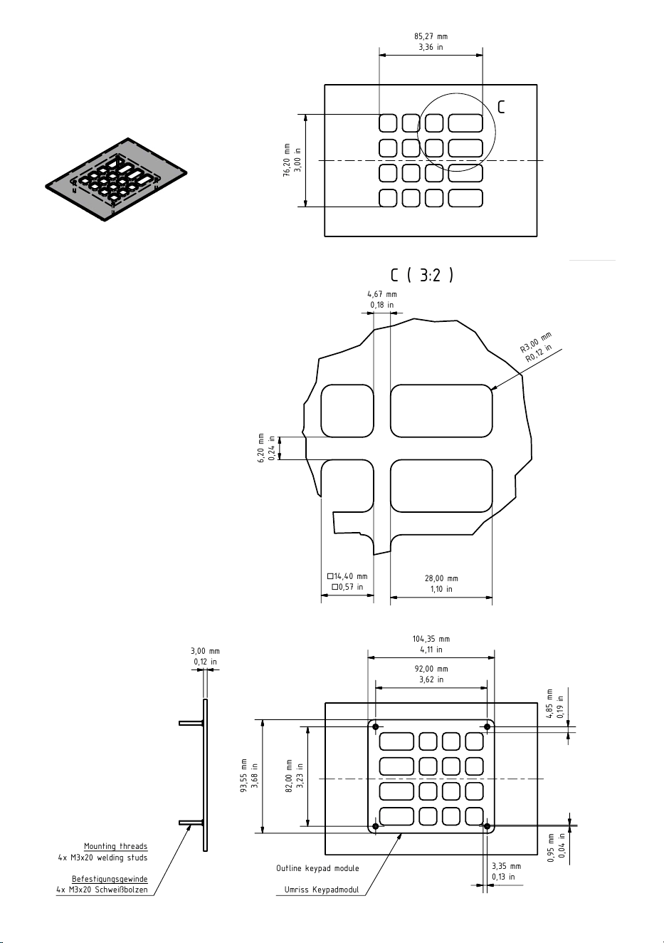
6
1
1
2
2
3
3
4
4
5
5
6
6
A A
B B
C C
D D
Page
1
EN: Assembly instructions and illustrations
- Front panel must be exactly 3mm thick.
- The DoorBird main electrical unit must be pressed flat against the front panel. A gasket is attached to the main electrical unit by us.
- Underneath the main electrical unit, there must be enough space planned for the Phoenix and CAT cabling (D21x: approx. 5 cm/1,97 in).
- In order to ensure problem-free installat
ion, a free area of at least 5 mm/0,2 in around each module.
DE: Montagehinweise und -zeichnungen
- Frontplatte muss genau 3mm stark sein.
- Die elektrische Haupteinheit des DoorBirds muss fl
ächig an die Frontplatte aufgepresst werden. Eine Dichtung ist von uns an der elektrischen Haupteinheit angebracht.
- Unterhalb der elektrischen Haupteinheit muss ausreichend Platz für die Phoenix- und CAT-Verkabelung eingeplant werden (D21x: ca. 5 cm/1,97 in).
- Um eine problemlose Montage gewährleisten zu können, sollte eine Freifläche von mindestens 5 mm/0,2 in um jedes Modul eingeplant werden.
DoorBird D2100E
Page/Seite 2
D21x Call Button / D21x Ruftaste
Page/Seite 3
Keypad Module with 16 keys /
Keypad Modul mit 16 Tasten
Page/Seite 4
Keypad Module with 12 keys /
Keypad Modul mit 12 Tasten
Page/Seite 5
Display-/Info Panel Module /
Display-/ Infopanel Modul
Page/Seite 6
IP Video Door Station
D21x series
C ( 3:2 )
C
1
1
2
2
3
3
4
4
5
5
6
6
A A
B B
C C
D D
Page
4
Format
A3
Scale
1:2
Drawn by
Checked by
Haraldsson Date
Schmidt Date
12.12.2019
12.12.2019
Bird Home Automation GmbH
Joachimsthaler Straße 12
D-10719 Berlin
Germany
Assembly instructions and illustrations
Montagehinweise und -zeichnungen
Keypad large (16 keys)
Material: stainless steel / rostfreier Edelstahl
V2A (1.4301); V4A (1.4404)
For technical support only /
Nur für den technischen Support
85,27 mm
3
,36 in
7
6
,
2
0
m
m
3
,
0
0
in
3,00 mm
0,12 in
104,35 mm
4,11 in
92,00 mm
3,62 in
9
3
,
5
5
m
m
3
,
6
8
in
8
2
,
0
0
m
m
3
,
2
3
in
4
,
8
5
m
m
0
,
1
9
in
4,67 mm
0,18 in
R
3
,
0
0
m
m
R
0
,
1
2
i
n
Outline keypad module
Umriss Keypadmodul
Mounting threads
4x M3x20 welding studs
Befestigungsgewinde
4x M3x20 Schweißbolzen
28,00 mm
1,10 in
14,40
mm
0,57 in
6
,
2
0
m
m
0
,
2
4
in
3,35 mm
0,13 in
0
,
9
5
m
m
0
,
0
4
in
C ( 3:2 )
C
1
1
2
2
3
3
4
4
5
5
6
6
A A
B B
C
C
D D
Page
4
Format
A3
Scale
1:2
Drawn by
Checked by
Haraldsson Date
Schmidt Date
12.12.2019
12.12.2019
Bird Home Automation GmbH
Joachimsthaler Straße 12
D-10719 Berlin
Germany
Assembly instructions and illustrations
Montagehinweise und -zeichnungen
Keypad large (16 keys)
Material: stainless steel / rostfreier Edelstahl
V2A (1.4301); V4A (1.4404)
For technical support only /
Nur für den technischen Support
85,27 mm
3
,36 in
7
6
,
2
0
m
m
3
,
0
0
in
3,00 mm
0,12 in
104,35 mm
4,11 in
92,00 mm
3,62 in
9
3
,
5
5
m
m
3
,
6
8
in
8
2
,
0
0
m
m
3
,
2
3
in
4
,
8
5
m
m
0
,
1
9
in
4,67 mm
0,18 in
R
3
,
0
0
m
m
R
0
,
1
2
i
n
Outline keypad module
Umriss Keypadmodul
Mounting threads
4x M3x20 welding studs
Befestigungsgewinde
4x M3x20 Schweißbolzen
28,00 mm
1,10 in
14,40
mm
0,57 in
6
,
2
0
m
m
0
,
2
4
in
3,35 mm
0,13 in
0
,
9
5
m
m
0
,
0
4
in
C ( 3:2 )
C
1
1
2
2
3
3
4
4
5
5
6
6
A A
B B
C
C
D D
Page
4
Format
A3
Scale
1:2
Drawn by
Checked by
Haraldsson Date
Schmidt Date
12.12.2019
12.12.2019
Bird Home Automation GmbH
Joachimsthaler Straße 12
D-10719 Berlin
Germany
Assembly instructions and illustrations
Montagehinweise und -zeichnungen
Keypad large (16 keys)
Material: stainless steel / rostfreier Edelstahl
V2A (1.4301); V4A (1.4404)
For technical support only /
Nur für den technischen Support
85,27 mm
3
,36 in
7
6
,
2
0
m
m
3
,
0
0
in
3,00 mm
0,12 in
104,35 mm
4,11 in
92,00 mm
3,62 in
9
3
,
5
5
m
m
3
,
6
8
in
8
2
,
0
0
m
m
3
,
2
3
in
4
,
8
5
m
m
0
,
1
9
in
4,67 mm
0,18 in
R
3
,
0
0
m
m
R
0
,
1
2
i
n
Outline keypad module
Umriss Keypadmodul
Mounting threads
4x M3x20 welding studs
Befestigungsgewinde
4x M3x20 Schweißbolzen
28,00 mm
1,10 in
14,40
mm
0,57 in
6
,
2
0
m
m
0
,
2
4
in
3,35 mm
0,13 in
0
,
9
5
m
m
0
,
0
4
in
C ( 3:2 )
C
1
1
2
2
3
3
4
4
5
5
6
6
A A
B B
C C
D D
Page
4
Format
A3
Scale
1:2
Drawn by
Checked by
Haraldsson Date
Schmidt Date
12.12.2019
12.12.2019
Bird Home Automation GmbH
Joachimsthaler Straße 12
D-10719 Berlin
Germany
Assembly instructions and illustrations
Montagehinweise und -zeichnungen
Keypad large (16 keys)
Material: stainless steel / rostfreier Edelstahl
V2A (1.4301); V4A (1.4404)
For technical support only /
Nur für den technischen Support
85,27 mm
3
,36 in
7
6
,
2
0
m
m
3
,
0
0
in
3,00 mm
0,12 in
104,35 mm
4,11 in
92,00 mm
3,62 in
9
3
,
5
5
m
m
3
,
6
8
in
8
2
,
0
0
m
m
3
,
2
3
in
4
,
8
5
m
m
0
,
1
9
in
4,67 mm
0,18 in
R
3
,
0
0
m
m
R
0
,
1
2
i
n
Outline keypad module
Umriss Keypadmodul
Mounting threads
4x M3x20 welding studs
Befestigungsgewinde
4x M3x20 Schweißbolzen
28,00 mm
1,10 in
14,40
mm
0,57 in
6
,
2
0
m
m
0
,
2
4
in
3,35 mm
0,13 in
0
,
9
5
m
m
0
,
0
4
in
Keypad Module with 16 keys /
Keypad Modul mit 16 Tasten
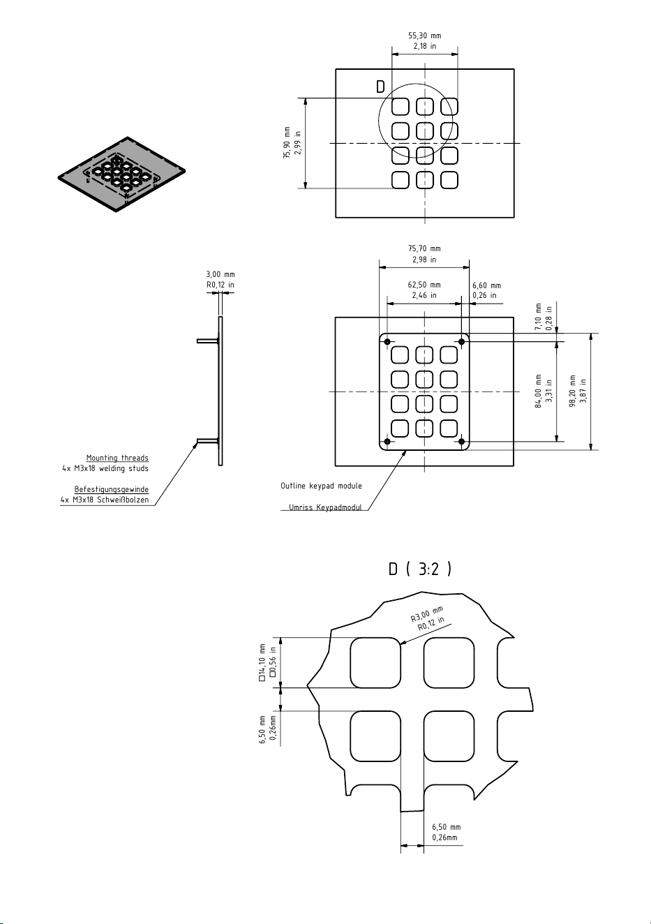
7
D ( 3:2 )
D
1
1
2
2
3
3
4
4
5
5
6
6
A A
B B
C C
D D
Page
5
Format
A3
Scale
1:2
Drawn by
Checked by
Haraldsson Date
Schmidt Date
12.12.2019
12.12.2019
Bird Home Automation GmbH
Joachimsthaler Straße 12
D-10719 Berlin
Germany
Assembly instructions and illustrations
Montagehinweise und -zeichnungen
Keypad small (12 keys)
Material: stainless steel / rostfreier Edelstahl
V2A (1.4301); V4A (1.4404)
For technical support only /
Nur für den technischen Support
Mounting threads
4x M3x18 welding studs
Befestigungsgewinde
4x M3x18 Schweißbolzen
Outline keypad module
Umriss Keypadmodul
55,30 mm
2,18 in
75,70 mm
2,98 in
62,50 mm
2,46 in
9
8
,
2
0
m
m
3
,
8
7
in
8
4
,
0
0
m
m
3
,
3
1
in
7
,
1
0
m
m
0
,
2
8
in
6,60 mm
0,26 in
1
4
,
1
0
m
m
0
,
5
6
in
6
,
5
0
m
m
0
,
2
6
m
m
R
3
,
0
0
m
m
R
0
,
1
2
i
n
3,00 mm
R0,12 in
7
5
,
9
0
m
m
2
,
9
9
in
6,50 mm
0,26mm
D ( 3:2 )
D
1
1
2
2
3
3
4
4
5
5
6
6
A A
B B
C C
D D
Page
5
Format
A3
Scale
1:2
Drawn by
Checked by
Haraldsson Date
Schmidt Date
12.12.2019
12.12.2019
Bird Home Automation GmbH
Joachimsthaler Straße 12
D-10719 Berlin
Germany
Assembly instructions and illustrations
Montagehinweise und -zeichnungen
Keypad small (12 keys)
Material: stainless steel / rostfreier Edelstahl
V2A (1.4301); V4A (1.4404)
For technical support only /
Nur für den technischen Support
Mounting threads
4x M3x18 welding studs
Befestigungsgewinde
4x M3x18 Schweißbolzen
Outline keypad module
Umriss Keypadmodul
55,30 mm
2,18 in
75,70 mm
2,98 in
62,50 mm
2,46 in
9
8
,
2
0
m
m
3
,
8
7
in
8
4
,
0
0
m
m
3
,
3
1
in
7
,
1
0
m
m
0
,
2
8
in
6,60 mm
0,26 in
1
4
,
1
0
m
m
0
,
5
6
in
6
,
5
0
m
m
0
,
2
6
m
m
R
3
,
0
0
m
m
R
0
,
1
2
i
n
3,00 mm
R0,12 in
7
5
,
9
0
m
m
2
,
9
9
in
6,50 mm
0,26mm
D ( 3:2 )
D
1
1
2
2
3
3
4
4
5
5
6
6
A A
B B
C C
D D
Page
5
Format
A3
Scale
1:2
Drawn by
Checked by
Haraldsson Date
Schmidt Date
12.12.2019
12.12.2019
Bird Home Automation GmbH
Joachimsthaler Straße 12
D-10719 Berlin
Germany
Assembly instructions and illustrations
Montagehinweise und -zeichnungen
Keypad small (12 keys)
Material: stainless steel / rostfreier Edelstahl
V2A (1.4301); V4A (1.4404)
For technical support only /
Nur für den technischen Support
Mounting threads
4x M3x18 welding studs
Befestigungsgewinde
4x M3x18 Schweißbolzen
Outline keypad module
Umriss Keypadmodul
55,30 mm
2,18 in
75,70 mm
2,98 in
62,50 mm
2,46 in
9
8
,
2
0
m
m
3
,
8
7
in
8
4
,
0
0
m
m
3
,
3
1
in
7
,
1
0
m
m
0
,
2
8
in
6,60 mm
0,26 in
1
4
,
1
0
m
m
0
,
5
6
in
6
,
5
0
m
m
0
,
2
6
m
m
R
3
,
0
0
m
m
R
0
,
1
2
i
n
3,00 mm
R0,12 in
7
5
,
9
0
m
m
2
,
9
9
in
6,50 mm
0,26mm
D ( 3:2 )
D
1
1
2
2
3
3
4
4
5
5
6
6
A A
B B
C C
D D
Page
5
Format
A3
Scale
1:2
Drawn by
Checked by
Haraldsson Date
Schmidt Date
12.12.2019
12.12.2019
Bird Home Automation GmbH
Joachimsthaler Straße 12
D-10719 Berlin
Germany
Assembly instructions and illustrations
Montagehinweise und -zeichnungen
Keypad small (12 keys)
Material: stainless steel / rostfreier Edelstahl
V2A (1.4301); V4A (1.4404)
For technical support only /
Nur für den technischen Support
Mounting threads
4x M3x18 welding studs
Befestigungsgewinde
4x M3x18 Schweißbolzen
Outline keypad module
Umriss Keypadmodul
55,30 mm
2,18 in
75,70 mm
2,98 in
62,50 mm
2,46 in
9
8
,
2
0
m
m
3
,
8
7
in
8
4
,
0
0
m
m
3
,
3
1
in
7
,
1
0
m
m
0
,
2
8
in
6,60 mm
0,26 in
1
4
,
1
0
m
m
0
,
5
6
in
6
,
5
0
m
m
0
,
2
6
m
m
R
3
,
0
0
m
m
R
0
,
1
2
i
n
3,00 mm
R0,12 in
7
5
,
9
0
m
m
2
,
9
9
in
6,50 mm
0,26mm
1
1
2
2
3
3
4
4
5
5
6
6
A A
B B
C C
D D
Page
1
EN: Assembly instructions and illustrations
- Front panel must be exactly 3mm thick.
- The DoorBird main electrical unit must be pressed flat against the front panel. A gasket is attached to the main electrical unit by us.
- Underneath the main electrical unit, there must be enough space planned for the Phoenix and CAT cabling (D21x: approx. 5 cm/1,97 in).
- In order to ensure problem-free installat
ion, a free area of at least 5 mm/0,2 in around each module.
DE: Montagehinweise und -zeichnungen
- Frontplatte muss genau 3mm stark sein.
- Die elektrische Haupteinheit des DoorBirds muss fl
ächig an die Frontplatte aufgepresst werden. Eine Dichtung ist von uns an der elektrischen Haupteinheit angebracht.
- Unterhalb der elektrischen Haupteinheit muss ausreichend Platz für die Phoenix- und CAT-Verkabelung eingeplant werden (D21x: ca. 5 cm/1,97 in).
- Um eine problemlose Montage gewährleisten zu können, sollte eine Freifläche von mindestens 5 mm/0,2 in um jedes Modul eingeplant werden.
DoorBird D2100E
Page/Seite 2
D21x Call Button / D21x Ruftaste
Page/Seite 3
Keypad Module with 16 keys /
Keypad Modul mit 16 Tasten
Page/Seite 4
Keypad Module with 12 keys /
Keypad Modul mit 12 Tasten
Page/Seite 5
Display-/Info Panel Module /
Display-/ Infopanel Modul
Page/Seite 6
IP Video Door Station
D21x series
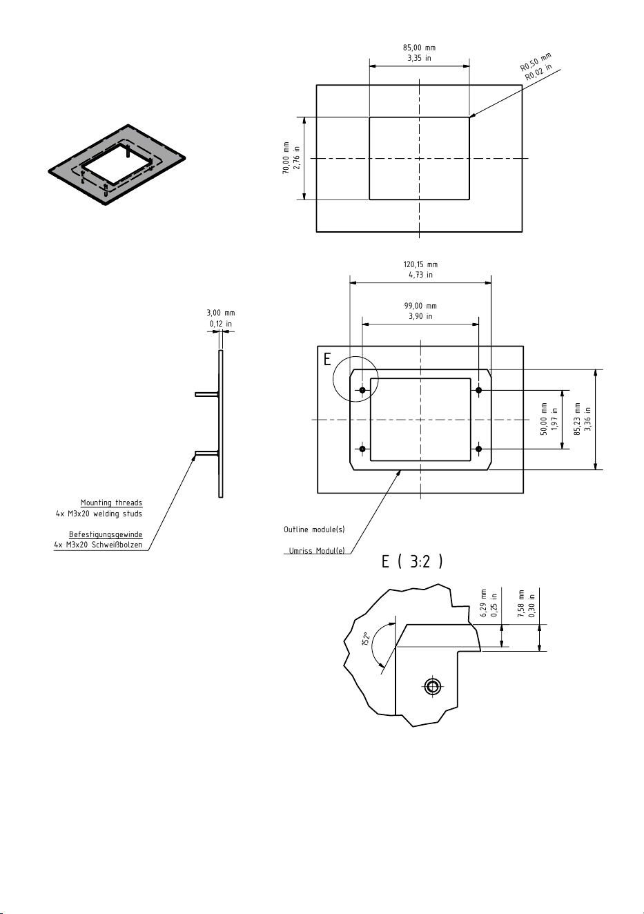
Keypad Module with 12 keys /
Keypad Modul mit 12 Tasten
8
E ( 3:2 )
E
1
1
2
2
3
3
4
4
5
5
6
6
A A
B B
C C
D D
Page
6
Format
A3
Scale
1:2
Drawn by
Checked by
Haraldsson Date
Schmidt Date
12.12.2019
12.12.2019
Bird Home Automation GmbH
Joachimsthaler Straße 12
D-10719 Berlin
Germany
Assembly instructions and illustrations
Montagehinweise und -zeichnungen
Display- & Info Panel Module
Material: stainless steel / rostfreier Edelstahl
V2A (1.4301); V4A (1.4404)
For technical support only /
Nur für den technischen Support
85,00 mm
3,35 in
7
0
,
0
0
m
m
2
,
7
6
in
R
0
,
5
0
m
m
R
0
,
0
2
i
n
3,00 mm
0,12 in
Mounting threads
4x M3x20 welding studs
Befestigungsgewinde
4x M3x20 Schweißbolzen
Outline module(s)
Umriss Modul(e)
99,00 mm
3,90 in
120,15 mm
4,73 in
5
0
,
0
0
m
m
1
,
9
7
in
8
5
,
2
3
m
m
3
,
3
6
in
1
5
2
°
6
,
2
9
m
m
0
,
2
5
in
7
,
5
8
m
m
0
,
3
0
in
E ( 3:2 )
E
1
1
2
2
3
3
4
4
5
5
6
6
A A
B B
C C
D D
Page
6
Format
A3
Scale
1:2
Drawn by
Checked by
Haraldsson Date
Schmidt Date
12.12.2019
12.12.2019
Bird Home Automation GmbH
Joachimsthaler Straße 12
D-10719 Berlin
Germany
Assembly instructions and illustrations
Montagehinweise und -zeichnungen
Display- & Info Panel Module
Material: stainless steel / rostfreier Edelstahl
V2A (1.4301); V4A (1.4404)
For technical support only /
Nur für den technischen Support
85,00 mm
3,35 in
7
0
,
0
0
m
m
2
,
7
6
in
R
0
,
5
0
m
m
R
0
,
0
2
i
n
3,00 mm
0,12 in
Mounting threads
4x M3x20 welding studs
Befestigungsgewinde
4x M3x20 Schweißbolzen
Outline module(s)
Umriss Modul(e)
99,00 mm
3,90 in
120,15 mm
4,73 in
5
0
,
0
0
m
m
1
,
9
7
in
8
5
,
2
3
m
m
3
,
3
6
in
1
5
2
°
6
,
2
9
m
m
0
,
2
5
in
7
,
5
8
m
m
0
,
3
0
in
E ( 3:2 )
E
1
1
2
2
3
3
4
4
5
5
6
6
A A
B B
C C
D D
Page
6
Format
A3
Scale
1:2
Drawn by
Checked by
Haraldsson Date
Schmidt Date
12.12.2019
12.12.2019
Bird Home Automation GmbH
Joachimsthaler Straße 12
D-10719 Berlin
Germany
Assembly instructions and illustrations
Montagehinweise und -zeichnungen
Display- & Info Panel Module
Material: stainless steel / rostfreier Edelstahl
V2A (1.4301); V4A (1.4404)
For technical support only /
Nur für den technischen Support
85,00 mm
3,35 in
7
0
,
0
0
m
m
2
,
7
6
in
R
0
,
5
0
m
m
R
0
,
0
2
i
n
3,00 mm
0,12 in
Mounting threads
4x M3x20 welding studs
Befestigungsgewinde
4x M3x20 Schweißbolzen
Outline module(s)
Umriss Modul(e)
99,00 mm
3,90 in
120,15 mm
4,73 in
5
0
,
0
0
m
m
1
,
9
7
in
8
5
,
2
3
m
m
3
,
3
6
in
1
5
2
°
6
,
2
9
m
m
0
,
2
5
in
7
,
5
8
m
m
0
,
3
0
in
E ( 3:2 )
E
1
1
2
2
3
3
4
4
5
5
6
6
A A
B B
C C
D D
Page
6
Format
A3
Scale
1:2
Drawn by
Checked by
Haraldsson Date
Schmidt Date
12.12.2019
12.12.2019
Bird Home Automation GmbH
Joachimsthaler Straße 12
D-10719 Berlin
Germany
Assembly instructions and illustrations
Montagehinweise und -zeichnungen
Display- & Info Panel Module
Material: stainless steel / rostfreier Edelstahl
V2A (1.4301); V4A (1.4404)
For technical support only /
Nur für den technischen Support
85,00 mm
3,35 in
7
0
,
0
0
m
m
2
,
7
6
in
R
0
,
5
0
m
m
R
0
,
0
2
i
n
3,00 mm
0,12 in
Mounting threads
4x M3x20 welding studs
Befestigungsgewinde
4x M3x20 Schweißbolzen
Outline module(s)
Umriss Modul(e)
99,00 mm
3,90 in
120,15 mm
4,73 in
5
0
,
0
0
m
m
1
,
9
7
in
8
5
,
2
3
m
m
3
,
3
6
in
1
5
2
°
6
,
2
9
m
m
0
,
2
5
in
7
,
5
8
m
m
0
,
3
0
in
1
1
2
2
3
3
4
4
5
5
6
6
A A
B B
C C
D D
Page
1
EN: Assembly instructions and illustrations
- Front panel must be exactly 3mm thick.
- The DoorBird main electrical unit must be pressed flat against the front panel. A gasket is attached to the main electrical unit by us.
- Underneath the main electrical unit, there must be enough space planned for the Phoenix and CAT cabling (D21x: approx. 5 cm/1,97 in).
- In order to ensure problem-free installat
ion, a free area of at least 5 mm/0,2 in around each module.
DE: Montagehinweise und -zeichnungen
- Frontplatte muss genau 3mm stark sein.
- Die elektrische Haupteinheit des DoorBirds muss fl
ächig an die Frontplatte aufgepresst werden. Eine Dichtung ist von uns an der elektrischen Haupteinheit angebracht.
- Unterhalb der elektrischen Haupteinheit muss ausreichend Platz für die Phoenix- und CAT-Verkabelung eingeplant werden (D21x: ca. 5 cm/1,97 in).
- Um eine problemlose Montage gewährleisten zu können, sollte eine Freifläche von mindestens 5 mm/0,2 in um jedes Modul eingeplant werden.
DoorBird D2100E
Page/Seite 2
D21x Call Button / D21x Ruftaste
Page/Seite 3
Keypad Module with 16 keys /
Keypad Modul mit 16 Tasten
Page/Seite 4
Keypad Module with 12 keys /
Keypad Modul mit 12 Tasten
Page/Seite 5
Display-/Info Panel Module /
Display-/ Infopanel Modul
Page/Seite 6
IP Video Door Station
D21x series
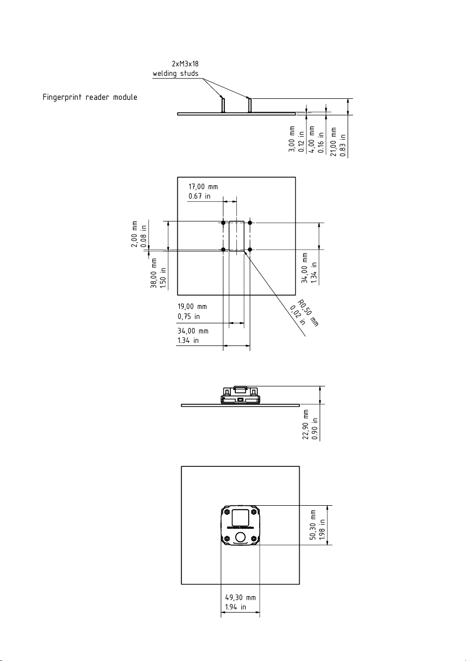
Display-/Info Panel Module /
Display-/ Infopanel Modul
9
1
1
2
2
3
3
4
4
5
5
6
6
A A
B B
C C
D D
Page
1
Format
A3
Drawing number
Fingerprint Reader Module
Designation
Fingerprint reader module
General tolerance
2768 -mK
Scale
Material:
General pinciples
of presentation
ISO 128-1
Bird Home Automation GmbH
Uhlandstr. 165
D-10719 Berlin
Germany
Confidential
34,00 mm
1.34 in
3
4
,
0
0
m
m
1
.3
4
in
19,00 mm
0,75 in
R
0
,
5
0
m
m
0
,
0
2
i
n
2
,
0
0
m
m
0
.0
8
in
17,00 mm
0.67 in
2xM3x18
welding studs
3
,
0
0
m
m
0
.1
2
in
4
,
0
0
m
m
0
.1
6
in
2
1
,
0
0
m
m
0
.8
3
in
49,30 mm
1.94 in
5
0
,
3
0
m
m
1
.9
8
in
2
2
,
9
0
m
m
0
.9
0
in
3
8
,
0
0
m
m
1
.5
0
in
1
1
2
2
3
3
4
4
5
5
6
6
A A
B B
C C
D D
Page
1
Format
A3
Drawing number
Fingerprint Reader Module
Designation
Fingerprint reader module
General tolerance
2768 -mK
Scale
Material:
General pinciples
of presentation
ISO 128-1
Bird Home Automation GmbH
Uhlandstr. 165
D-10719 Berlin
Germany
Confidential
34,00 mm
1.34 in
3
4
,
0
0
m
m
1
.3
4
in
19,00 mm
0,75 in
R
0
,
5
0
m
m
0
,
0
2
i
n
2
,
0
0
m
m
0
.0
8
in
17,00 mm
0.67 in
2xM3x18
welding studs
3
,
0
0
m
m
0
.1
2
in
4
,
0
0
m
m
0
.1
6
in
2
1
,
0
0
m
m
0
.8
3
in
49,30 mm
1.94 in
5
0
,
3
0
m
m
1
.9
8
in
2
2
,
9
0
m
m
0
.9
0
in
3
8
,
0
0
m
m
1
.5
0
in
1
1
2
2
3
3
4
4
5
5
6
6
A A
B
B
C C
D D
Page
1
Format
A3
Drawing number
Fingerprint Reader Module
Designation
Fingerprint reader module
General tolerance
2768 -mK
Scale
Material:
General pinciples
of presentation
ISO 128-1
Bird Home Automation GmbH
Uhlandstr. 165
D-10719 Berlin
Germany
Confidential
34,00 mm
1.34 in
3
4
,
0
0
m
m
1
.3
4
in
19,00 mm
0,75 in
R
0
,
5
0
m
m
0
,
0
2
i
n
2
,
0
0
m
m
0
.0
8
in
17,00 mm
0.67 in
2xM3x18
welding studs
3
,
0
0
m
m
0
.1
2
in
4
,
0
0
m
m
0
.1
6
in
2
1
,
0
0
m
m
0
.8
3
in
49,30 mm
1.94 in
5
0
,
3
0
m
m
1
.9
8
in
2
2
,
9
0
m
m
0
.9
0
in
3
8
,
0
0
m
m
1
.5
0
in
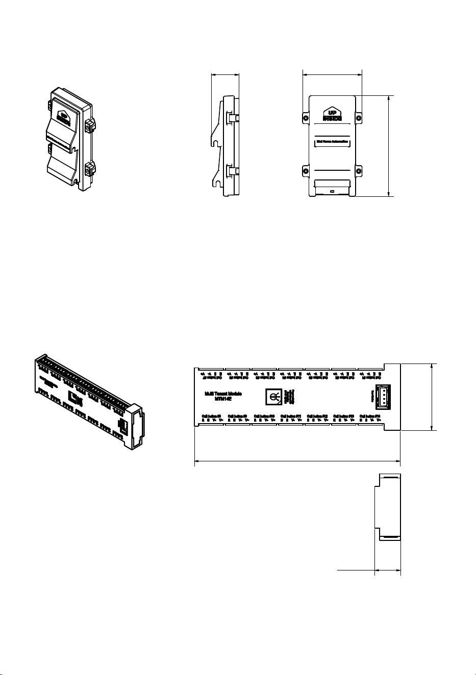
Fingerprint reader module /
Fingerabdrucklesermodul
10
Page
1
Format
A4
Drawing number
MTM14E
Designation
MTM14E
General tolerance
2768 -mK
Scale
Material:
General pinciples
of presentation
ISO 128-1
Bird Home Automation GmbH
Uhlandstr. 165
D-10719 Berlin
Germany
Confidential
128,20 mm
5.05 in
4
1
,
5
0
m
m
1
.6
3
in
16,10 mm
0.63 in
Page
1
Format
A4
Drawing number
MTM14E
Designation
MTM14E
General tolerance
2768 -mK
Scale
Material:
General pinciples
of presentation
ISO 128-1
Bird Home Automation GmbH
Uhlandstr. 165
D-10719 Berlin
Germany
Confidential
128,20 mm
5.05 in
4
1
,
5
0
m
m
1
.6
3
in
16,10 mm
0.63 in
Page
1
Format
A4
Drawing number
MTM14E
Designation
MTM14E
General tolerance
2768 -mK
Scale
Material:
General pinciples
of presentation
ISO 128-1
Bird Home Automation GmbH
Uhlandstr. 165
D-10719 Berlin
Germany
Confidential
128,20 mm
5.05 in
4
1
,
5
0
m
m
1
.6
3
in
16,10 mm
0.63 in
Page
1
Format
A4
Drawing number
MTM56S
Designation
MTM56S
General tolerance
2768 -mK
Scale
Material:
General pinciples
of presentation
ISO 128-1
Bird Home Automation GmbH
Uhlandstr. 165
D-10719 Berlin
Germany
Confidential
74,00 mm
2.91 in
1
2
5
,
4
1
m
m
4
.9
4
in
34,50 mm
1.36 in
Page
1
Format
A4
Drawing number
MTM56S
Designation
MTM56S
General tolerance
2768 -mK
Scale
Material:
General pinciples
of presentation
ISO 128-1
Bird Home Automation GmbH
Uhlandstr. 165
D-10719 Berlin
Germany
Confidential
74,00 mm
2.91 in
1
2
5
,
4
1
m
m
4
.9
4
in
34,50 mm
1.36 in
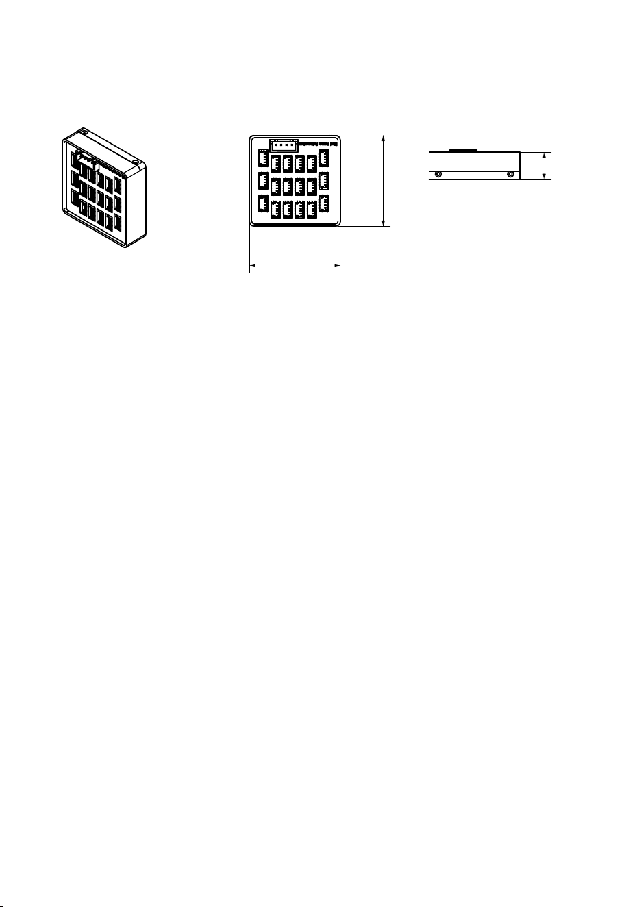
MTM56S
MTM14E
11
It is possible that these manual still contains typographical errors
or printing errors.The information in this manual will be checked
regularly and corrections will be made in the next version. We accept
no liability for errors of a technical or printing nature and their
consequences.
Es ist möglich, dass die vorliegende Anleitung noch drucktechnische
Mängel oder Druckfehler aufweist. Die Angaben in dieser Anleitung
werden jedoch regelmäßig überprüft und Korrekturen in der
nächsten Ausgabe vorgenommen. Für Fehler technischer oder
drucktechnischer Art und ihre Folgen übernehmen wir keine Haftung.
Page
1
Format
A4
Drawing number
MTM1BA
Designation
MTM1BA
General tolerance
2768 -mK
Scale
Material:
General pinciples
of presentation
ISO 128-1
Bird Home Automation GmbH
Uhlandstr. 165
D-10719 Berlin
Germany
Confidential
4
2
,
0
0
m
m
1
.6
5
in
42,00 mm
1.65 in
1
2
,
6
0
m
m
0
.5
0
in
Page
1
Format
A4
Drawing number
MTM1BA
Designation
MTM1BA
General tolerance
2768 -mK
Scale
Material:
General pinciples
of presentation
ISO 128-1
Bird Home Automation GmbH
Uhlandstr. 165
D-10719 Berlin
Germany
Confidential
4
2
,
0
0
m
m
1
.6
5
in
42,00 mm
1.65 in
1
2
,
6
0
m
m
0
.5
0
in
Page
1
Format
A4
Drawing number
MTM1BA
Designation
MTM1BA
General tolerance
2768 -mK
Scale
Material:
General pinciples
of presentation
ISO 128-1
Bird Home Automation GmbH
Uhlandstr. 165
D-10719 Berlin
Germany
Confidential
4
2
,
0
0
m
m
1
.6
5
in
42,00 mm
1.65 in
1
2
,
6
0
m
m
0
.5
0
in
MTM18A

www.doorbird.com