

M4 MkII Owner’s
Manual

Table of contents
▪ 1: Product Safety and Conformity . . . . . . . . . . . . . . . . . . . . . . . . . . . . . . . . . . . . . . . . . . . . . . . . . . . . 3
▪ 2: Introduction . . . . . . . . . . . . . . . . . . . . . . . . . . . . . . . . . . . . . . . . . . . . . . . . . . . . . . . . . . . . . . . . . . 5
▪ 3: Installation . . . . . . . . . . . . . . . . . . . . . . . . . . . . . . . . . . . . . . . . . . . . . . . . . . . . . . . . . . . . . . . . . . . 6
▪ 3.1: Electrical Installation . . . . . . . . . . . . . . . . . . . . . . . . . . . . . . . . . . . . . . . . . . . . . . . . . . . . . . . 7
▪ Mains Supply . . . . . . . . . . . . . . . . . . . . . . . . . . . . . . . . . . . . . . . . . . . . . . . . . . . . . . . . . . . . 7
▪ Speaker Cables . . . . . . . . . . . . . . . . . . . . . . . . . . . . . . . . . . . . . . . . . . . . . . . . . . . . . . . . . . 7
▪ Signal Wiring . . . . . . . . . . . . . . . . . . . . . . . . . . . . . . . . . . . . . . . . . . . . . . . . . . . . . . . . . . . . 7
▪ 3.2: Positioning . . . . . . . . . . . . . . . . . . . . . . . . . . . . . . . . . . . . . . . . . . . . . . . . . . . . . . . . . . . . . 11
▪ Orientation . . . . . . . . . . . . . . . . . . . . . . . . . . . . . . . . . . . . . . . . . . . . . . . . . . . . . . . . . . . . . 11
▪ 4: Setting up and adjusting. . . . . . . . . . . . . . . . . . . . . . . . . . . . . . . . . . . . . . . . . . . . . . . . . . . . . . . . 13
▪ 4.1A: First time power up DA40/80-DSP . . . . . . . . . . . . . . . . . . . . . . . . . . . . . . . . . . . . . . . . . . 14
▪ 4.1B: First time power up DCA800/1400 with filters . . . . . . . . . . . . . . . . . . . . . . . . . . . . . . . . . . 15
▪ 4.2: Running in . . . . . . . . . . . . . . . . . . . . . . . . . . . . . . . . . . . . . . . . . . . . . . . . . . . . . . . . . . . . . 16
▪ 4.3: Testing and alignment. . . . . . . . . . . . . . . . . . . . . . . . . . . . . . . . . . . . . . . . . . . . . . . . . . . . . 17
▪ Correct installation check . . . . . . . . . . . . . . . . . . . . . . . . . . . . . . . . . . . . . . . . . . . . . . . . . . 17
▪ Fine frequency balance. . . . . . . . . . . . . . . . . . . . . . . . . . . . . . . . . . . . . . . . . . . . . . . . . . . . 17
▪ System Gain/Level Calibration . . . . . . . . . . . . . . . . . . . . . . . . . . . . . . . . . . . . . . . . . . . . . . . 17
▪ 5: Protection . . . . . . . . . . . . . . . . . . . . . . . . . . . . . . . . . . . . . . . . . . . . . . . . . . . . . . . . . . . . . . . . . . 19
▪ 6: Care and Maintenance . . . . . . . . . . . . . . . . . . . . . . . . . . . . . . . . . . . . . . . . . . . . . . . . . . . . . . . . . 20
▪ 7: Servicing & Spare parts . . . . . . . . . . . . . . . . . . . . . . . . . . . . . . . . . . . . . . . . . . . . . . . . . . . . . . . . 21
▪ 8: Technical Specifications . . . . . . . . . . . . . . . . . . . . . . . . . . . . . . . . . . . . . . . . . . . . . . . . . . . . . . . . 22
▪ 9: Appendix 1: DSP . . . . . . . . . . . . . . . . . . . . . . . . . . . . . . . . . . . . . . . . . . . . . . . . . . . . . . . . . . . . . 23
▪ Setup sequence . . . . . . . . . . . . . . . . . . . . . . . . . . . . . . . . . . . . . . . . . . . . . . . . . . . . . . . . . . . . 24
2 M4 MkII Owner’s Manual
1: Product Safety and
Conformity
The M4 MkII is a professional loudspeaker intended for professional users working in a professional environment;
therefore, a certain level of knowledge of audio equipment operation is assumed.
About this guide
Used expressions and symbols
In this guide, the following signs and symbols are used:
The exclamation point within an equilateral triangle is intended to alert the user to the presence of important
operating and maintenance (servicing) instructions in the literature accompanying the product.
WARNING
Indicates, in combination with a safety sign, a potentially hazardous situation which, if not avoided, could result in
death or serious injury.
Important safety instructions
1. Read these instructions.
2. Keep these instructions.
3. Heed all warnings.
4. Follow all instructions.
5. Do not use this apparatus near water.
6. Clean only with a dry cloth.
7. Do not install near any heat sources such as radiators, heat registers, stoves, or other apparatus (including
amplifiers) that produce heat.
8. Only use attachments/accessories specified by the manufacturer.
9. Use only with the cart, stand, tripod, bracket, or table specified by the manufacturer, or sold with the
apparatus. When a cart is used, use caution when moving the cart/apparatus combination to avoid injury
from tip-over.
10. No naked flame sources, such as lighted candles, should be placed on the apparatus.
WARNING
To reduce the risk of fire or electric shock, this apparatus should not be exposed to rain or moisture and objects
filled with liquids, such as vases, should not be placed on this apparatus.
WARNING
1: Product Safety and Conformity 3

Our speakers are very heavy. Ensure appropriate lifting methods are employed when moving them.
WARNING
Never place a loudspeaker in an unstable location. A loudspeaker may fall, causing serious personal injury or
death. Use only appropriate stands or brackets to mount the loudspeaker.
High sound pressure levels
To prevent possible hearing damage, avoid listening at high volume levels for extended periods of time.
Unpacking
After unpacking, ensure the system is complete and inspect the device and all accessories for any transport
damage. Transport damage may be expected if the packaging is already severely damaged. Do not attempt to
start up a damaged device.
If the contents are incomplete or damaged, please contact your Dynaudio distributor.
Distributor addresses can be found on the Internet at dynaudio.com.
Removing the protection cap
The tweeter is protected by a cap to prevent damage during transport and unpacking. After you have unpacked
the speaker, remove the cap by just pulling it straight out.
Packaging material
The packaging has been designed to be reusable, provided it has not been damaged during transport. Keep the
original packaging and use it for all further transport.
CE declaration of conformity
The CE declaration of conformity can be found online:
https://dynaudio.com/support/ce-conformity-declarations
Correct disposal of this product
This marking on the product, accessories, packaging or literature indicates that the product and its electronic
accessories should not be disposed of with other household waste as stated in the European Directive 2012/19/
EU on Waste Electrical and Electronic Equipment (WEEE). The crossed-out bin symbol is printed on all products
as a reminder.
By ensuring this product is disposed of correctly, you will help prevent potential negative consequences for the
environment and human health. Recycling of materials helps to conserve natural resources.
Household users should contact either the retailer where they purchased this product or their local government
oce for details on where and how to recycle these items in an environmentally safe manner.
Business users should contact their supplier and check the terms and conditions of the purchase contract. This
product and its electronic accessories should not be mixed with other commercial wastes for disposal.
Waste may be taken to a special collection site or can be delivered free of charge to the dealer when purchasing
a new equivalent or without obligation to make a new purchase for equipment smaller than 25 cm.
4 M4 MkII Owner’s Manual

2: Introduction
The M4 MkII is a 4-way active/passive monitor system employing external frequency dividers and power
amplification. It is designed as a high-quality all-purpose monitor for medium to large-sized control rooms.
The external electronic components for the M4 MkII will typically comprise the Dynaudio Acoustics DA40/80-DSP
power amplifiers with built-in DSP, with the ND variants in support, or a set of Dynaudio Acoustics DCA800/1400
amplifiers with an external crossover/processor, such as an XTA DP448. It is also possible to configure the system
with DCA800/1400 amplifiers, which feature built-in filters, for those who prefer a purely analogue system.
There are several dierent amplifier configurations possible for the M4 MkII. Please consult with your dealer or our
in-house technical support to advise on the best solution.
The system’s hybrid crossover design utilises a combination of active and passive crossover filters to achieve
optimal performance.
The M4 has four bass drivers. These are configured as two pairs with a separate amp channel powering each
pair. This is to give the best quality reproduction and avoid issues with damping factor, cable impedance, etc.
For surround monitoring applications, the M4 MkII is typically complemented by a sub-bass loudspeaker system,
along with surround speakers as needed.
The M4 MkII is capable of delivering high-quality, distortion-free monitoring in medium- to large-sized studios, with
optimum imaging and a very wide frequency response. The system’s ability to achieve these goals, however, is
dependent on the acoustic quality of the environment into which it is introduced, the quality of the electrical
installation, and the accuracy of the final crossover alignment.
Dynaudio Acoustics strongly recommends that the final setup and alignment be carried out by a qualified engineer
with extensive expertise in acoustics and the appropriate test equipment required to align the M4 MkII system.
Your local dealer is available for consultation prior to and during installation to oer advice and design expertise on
all aspects of the room layout and system installation.
For detailed information on the amplifiers and crossovers used in your system, please consult the relevant
handbook supplied with the units.
2: Introduction 5

3: Installation
6 M4 MkII Owner’s Manual

3.1: Electrical Installation
In view of the “custom” nature of every installation for a monitor of this type, no cabling is supplied. The following
are required for the electrical installation of the M4 MkII system.
Mains Supply
At full power, a stereo M4 MkII system can draw around 5 kW from the mains supply. Ensure that the mains
supply is capable of supplying this amount of power with ease. Indeed, it is often advisable to run a separate spur
from the mains distribution box with a 20 or 32 amp breaker (40 or 64 amp for 120v) fitted.
To avoid earth loops, try to run all units from the same distribution box and ensure that the mains earth is of high
quality. Avoid “daisy-chaining” mains blocks for earthing and power handling reasons. Ideally, this should be on
the same ring/spur as the source equipment.
Speaker Cables
The connections between the speaker and amplifier should be kept as short as possible. The cable itself should
be high-quality speaker cable, eg 4mm² or 6mm² oxygen-free multi-strand copper. The speaker terminations are
on Gold screw down terminals.
The outputs of the amplifiers are on speakON connectors.
Signal Wiring
The inputs and interconnections are balanced XLR connections. Always ensure that only high-quality XLR cables
are used for connection to the amplifiers. Typical system wiring configurations are shown in Figures 2 and 3.
Figure 1: M4 MkII Connector panels, red indicates +ve. The LF panel is nearest the edge of the cabinet.
3: Installation 7
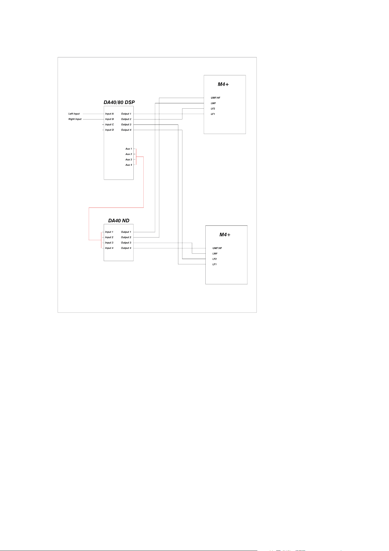
Figure 2: Typical Stereo M4 MkII system with DA40/80 amplifiers
8 M4 MkII Owner’s Manual
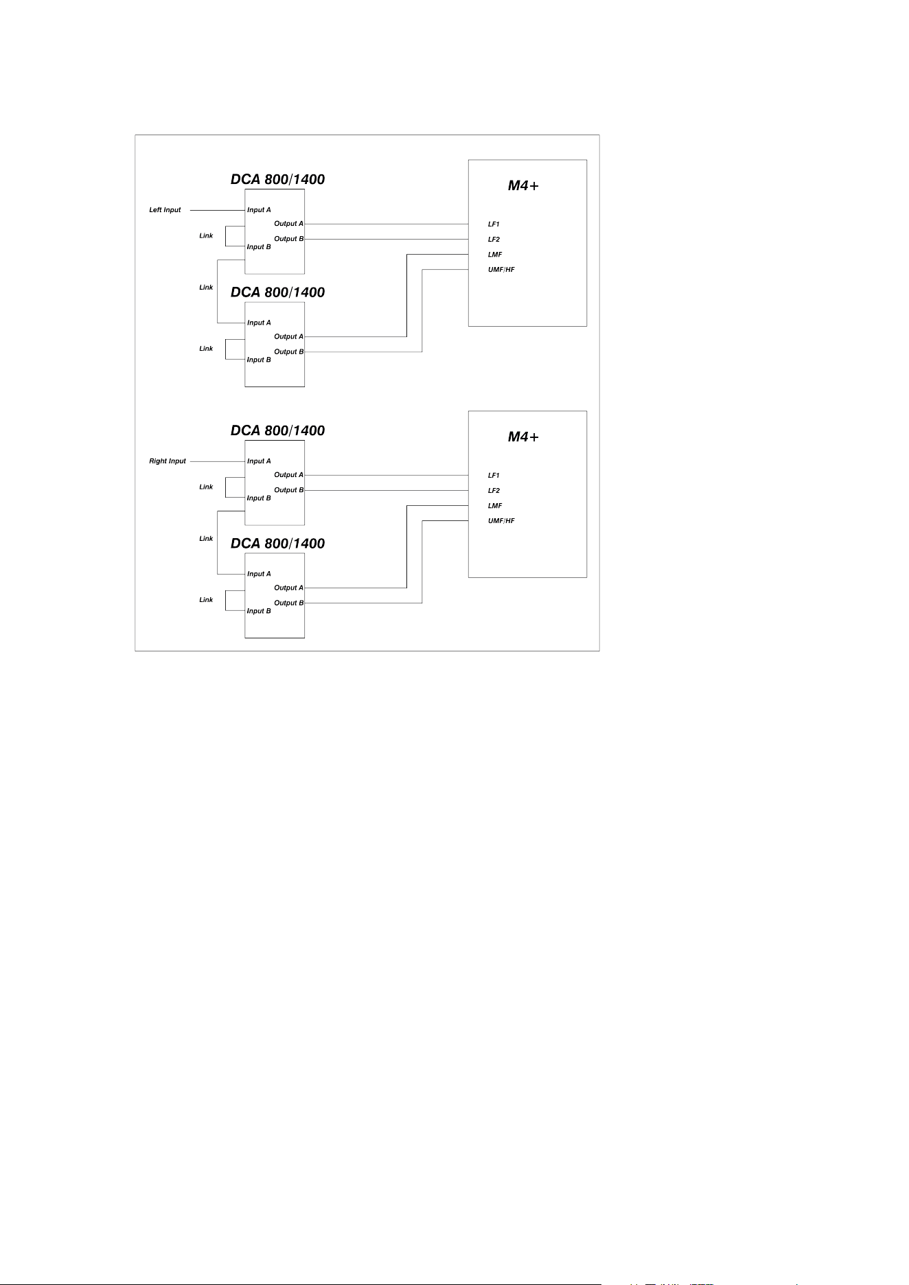
Figure 3: Typical Stereo M4 MkII system with DCA amplifiers with filters
3: Installation 9
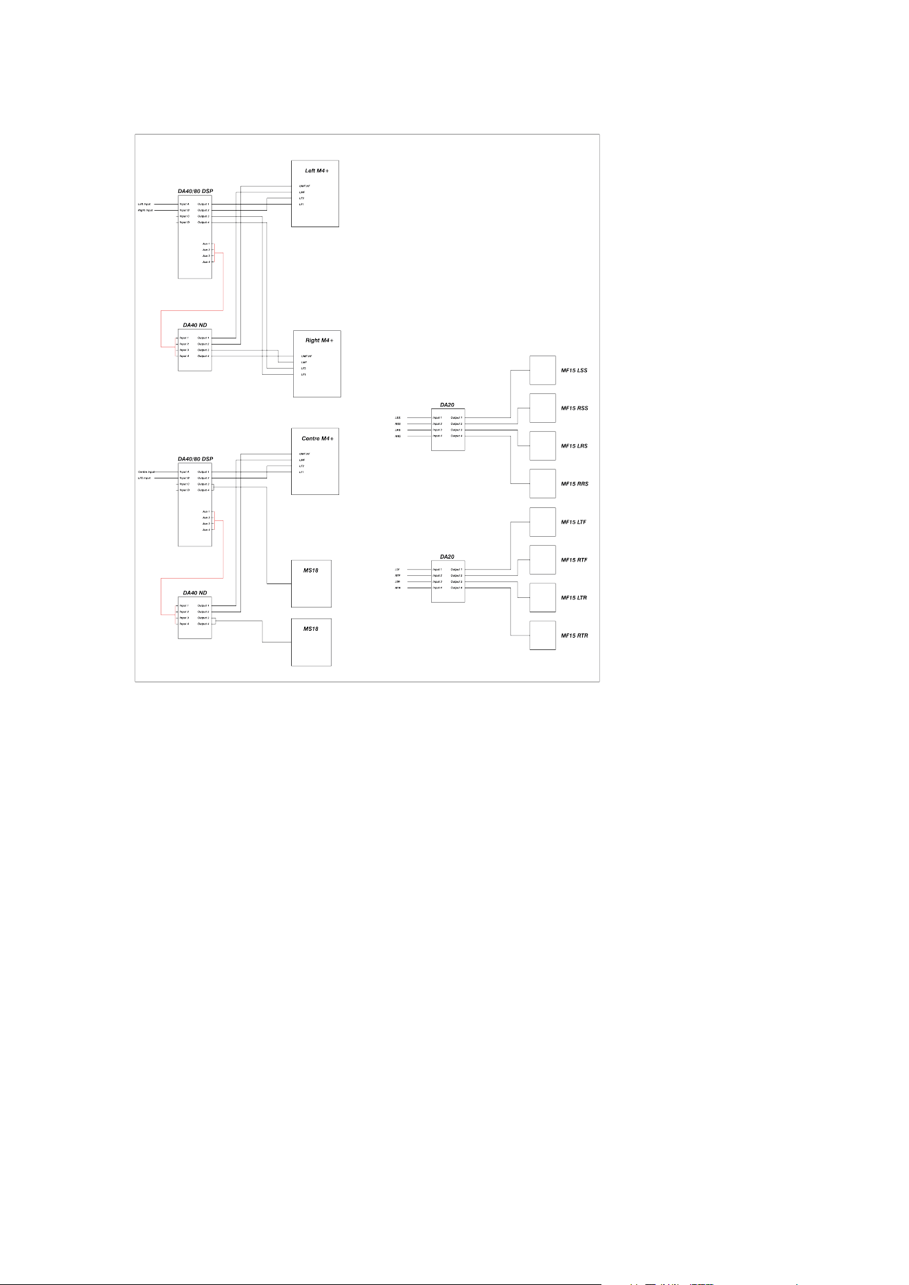
Figure 4: Typical M4 MkII based Atmos 7.1.4 system with DA40/80/20 amplifiers
10 M4 MkII Owner’s Manual
3.2: Positioning
The M4 MkII loudspeaker is typically flush-mounted into a wall, although it can be stand-mounted. Low-frequency
performance will be increased if the M4 MkII is wall-mounted in appropriate monitor housings. The room itself
should be properly acoustically treated to avoid compromising the performance potential of the M4 MkII.
The optimum distance from the speaker to the listener is in the range of 2 to 6 meters.
The acoustic centre of the M4 MkII is midway between the low mid drivers. This point should be angled towards
the mixing position, both horizontally and vertically, to ensure the ecient acoustical summing of all the drivers.
If the studio is seeking approval and licensing from Dolby, THX or a similar entity, then these parties or qualified
acoustic consultants should be consulted prior to installation, so that their specific requirements can be met.
If the M4 MkII is to be used behind a screen, then a woven, acoustically transparent screen must be used. These
oer very small amounts of acoustic attenuation at high frequencies. The traditional perforated screen (as used in
cinemas) will require a potentially damaging amount of high-frequency boost to maintain a flat frequency response.
Orientation
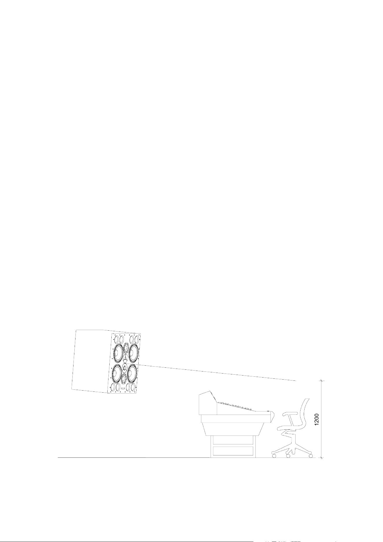
The illustration below demonstrates the optimum speaker orientation for a stereo M4 MkII system.
The M4 MkII cabinets should subtend at an angle of 60 degrees from the mix position to form an equilateral
triangle between the two loudspeakers and the mix position. The distance between the mix position and each M4
MkII should be no less than 2m to ensure correct acoustical summing of drivers.
Setout is based on the speaker acoustic centre (midway between the two low mid drivers)
The cabinets should be set at a height such that the LMF, UMF and HF drivers have a clear path to the mix
position with no screens, meter bridges, nearfields, etc. in the way. This may require tilting the speaker to aim the
acoustic centre of the M4 MkII directly at the mix position. It is acceptable for the bass driver to be partially
occluded.
The aiming point at the mix position is typically 1.2m o the floor, but this can be varied to suit individual users.
Dolby Atmos HE guidelines recommend a listening height of 1.2 m.
Figure 5a: Typical Stereo M4 MkII layout – side view
3: Installation 11
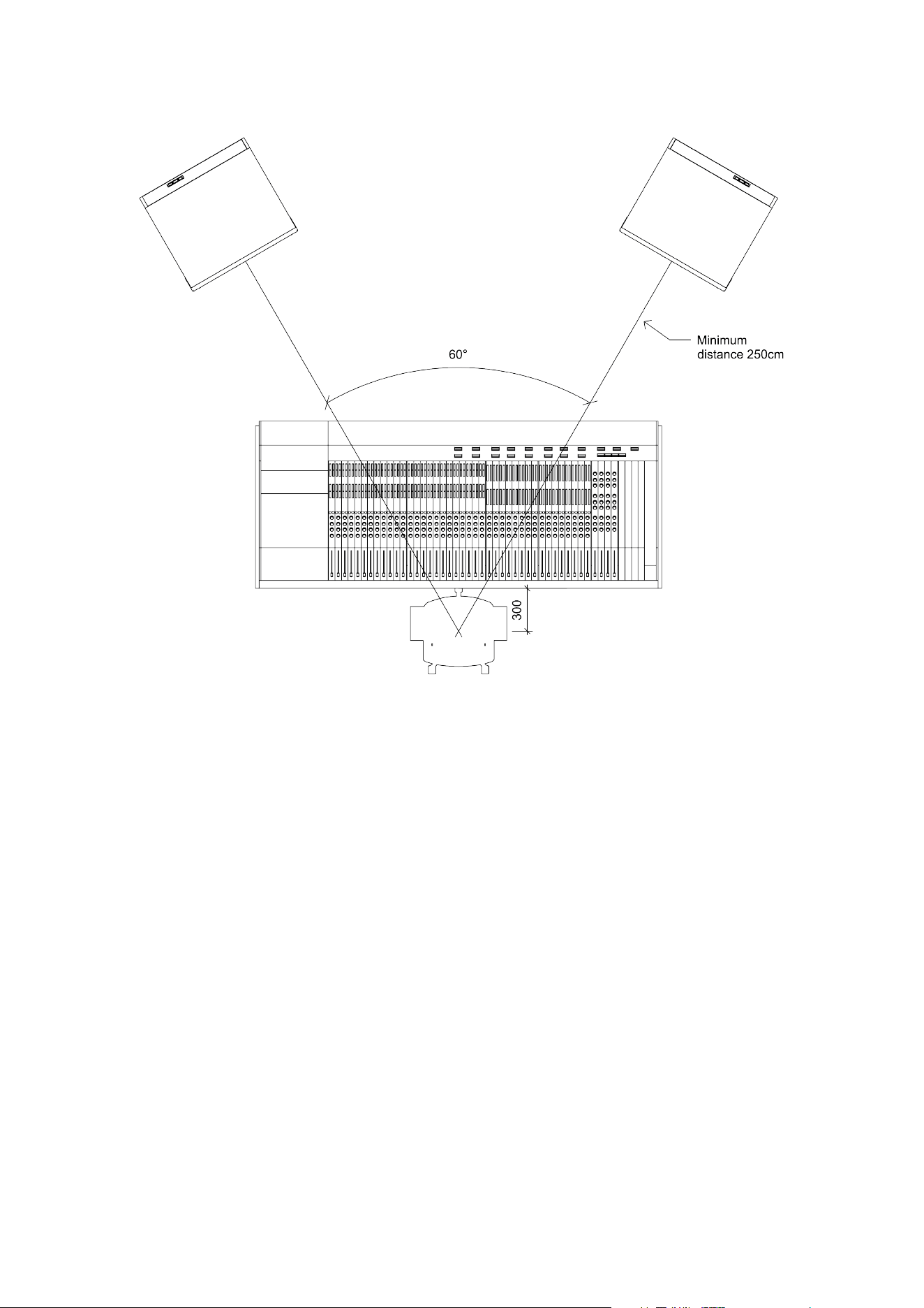
Figure 5b: Typical Stereo M4 MkII layout – top view
12 M4 MkII Owner’s Manual

4: Setting up and
adjusting
4: Setting up and adjusting 13

4.1A: First time power up DA40/
80-DSP
Check that the system has been wired and set up according to the previous instructions. Ensure all amplifiers are
o, then proceed as follows.
1. Firstly, the DSP in the DA40 must be programmed. We will supply a setup file that can be loaded into the
unit to set the base crossover filters, etc. To control the DSP, you will need the AudioCore Amped Edition
software from MC2 Audio. Refer to Appendix 1 for more information on this.
2. Once programmed, commissioning checks can be carried out.
3. Set the power amp output level controls to minimum. If any mains hum or buzz is heard at this point,
proceed directly to the section on Hum and Buzz and address this issue before continuing. Turn the
power amps up to about half power and check again for hum and buzz.
4. Set a very low-level signal playing into the system. Pink noise is best, but music can be used. The signal
must be low-level to avoid possible damage to drivers if connected to the wrong frequency band output
from the crossovers. Unmute each band on the crossover in turn and check that the correct signal is
coming from the correct drive unit(s). Start with the high-frequency bands and work down – this will
minimise the risk of applying low-frequency signals to high-frequency drivers.
5. If everything appears to be connected correctly, unmute all the bands together. Using a known piece of
music, adjust the band output level controls by ear to get a reasonably balanced sound from the system. It
is now ready to be run in.
6. Save this crossover setting to a new memory location. This will become your “working setup” and should
be used for all subsequent testing and adjustment. If you experience any issues with this setup, you can
revert to the original M4 MkII setup. We recommend that you keep this memory unchanged.
14 M4 MkII Owner’s Manual

4.1B: First time power up DCA800/
1400 with filters
Check that the system has been wired and set up according to the previous instructions. Ensure all amplifiers are
o, then proceed as follows.
1. If used, switch the system controllers on. The crossovers should be muted at this point. (Ignore this step if
using amps with internal crossovers.)
2. Set the power amp level controls to minimum and switch them on in turn. If any mains hum or buzz is
heard at this point, proceed directly to the section on Hum and Buzz and address this issue before
continuing. Turn the power amps up to about half power and check again for hum and buzz.
3. Set a very low-level signal playing into the system. Pink noise is best, but music can be used. The signal
must be low-level to avoid possible damage to drivers if connected to the wrong frequency band output
from the crossovers. Verify that the correct signal is being transmitted from the correct drive unit(s) by
turning each level control up one at a time. Start with the high-frequency bands and work down – this will
minimise the risk of applying low-frequency signals to high-frequency drivers.
4. If everything appears to be connected correctly, set all bands to -10. Using a known piece of music,
adjust the band level controls by ear to get a reasonably balanced sound from the system. It is now ready
to be run in.
4: Setting up and adjusting 15

4.2: Running in
Running in is essential before any fine-tuning is performed, any judgments are passed, or the system is subjected
to the maximum level. Failure to observe this can permanently damage the drivers, resulting in degraded
performance for the system’s lifetime. The easiest way to run a system in is to set the level controls roughly by ear
as above, then connect a continuous music source (eg, a CD player in repeat mode) and leave it to run for at
least 12 hours at medium volume levels (you may need to set the amplifier gains to -10 dB). This will achieve a
minimum of running in, after which a proper adjustment can be made. The system will be run in fully after 5 to 6
days of continuous use, at which stage fine-tuning should be performed. Note that if the system is left unused for
a period of time (days), it may take a few minutes to return to normal performance after being switched on.
16 M4 MkII Owner’s Manual

4.3: Testing and alignment
Once the system is suciently operational, it can be properly aligned. Dynaudio Acoustics strongly recommends
that the final setup and alignment be carried out by a qualified engineer with extensive expertise in acoustics and
the use of the appropriate test equipment that is required to align the M4 MkII system. Please contact our in-
house technical support team if you require any assistance.
The alignment procedure can be split into three stages as follows:
Correct installation check
Ensure that all components are wired correctly and functioning properly. Make some measurements and adjust
the band levels so that the system is nominally flat. In a symmetrical control room, there should be only minor
dierences in the left and right level settings. Verify that all drivers are correctly phased, culminating in a summing
check to ensure the entire system is in phase.
Fine frequency balance
Once correct phasing and system operation have been confirmed, the “fine-tuning” can take place.
If the DSP amplifier or external XTA crossovers are in use, there is much scope for fine-tuning the system. The
crossover filters should not be changed, as they are carefully matched to the driver’s performance. Individual band
gain, equalisation and overall time delay can be adjusted to give optimum results. (see handbook for the unit in
use).
This stage should be carried out by a qualified engineer who has the appropriate experience and test equipment
to set up a system like this.
When using the DCA amplifiers with built-in crossover filters, there is limited adjustment available. In addition to the
amplifier level controls, which let you balance the bass against the mids and highs, there is an LF and HF
equaliser. These are essentially shelving filters, operating at each end of the frequency range, to provide some
adjustment and allow for speaker positioning and personal taste. To access these, the lid of the amplifier must be
removed. The controls consist of two small blue potentiometers mounted on the small circuit boards, which are
raised above the main circuit board towards the rear of the unit.
The amplifier must be disconnected from the mains before removing the top cover! This
operation should only be carried out by experienced personnel.
In any room, various room eects will corrupt the perfectly flat response available from the M4 MkII, although it
should be possible to get a reasonably good response. If serious dips, peaks or notches are visible in the
frequency response, the room may require specific acoustic treatment by a reputable acoustic consultant. It may
be possible to fix minor anomalies in the response using the equalisation options in the crossover. The final setup
must be thoroughly tested to ensure it is backed up by extensive listening tests.
System Gain/Level Calibration
The gain through the system needs to be set so that either:
1. The maximum level from the speakers is reached near the maximum position of the monitor pot
(uncalibrated operation)
2. A known SPL is experienced for a given input signal level (calibrated operation)
4: Setting up and adjusting 17

In uncalibrated operation, it is simply a matter of adjusting the gain through the system so that the level from the
speakers coincides with the position of the monitor pot. If there is too much gain, maximum levels will be reached
before the monitor pot is near the end of its travel, which will encourage overdriving of the system and cause
damage. If, on the other hand, there is too little gain, the monitor pot reaches the end of its travel before full
system performance is achieved. Although this gives good protection, it may encourage overdriving of the
console.
For post-production use, it is common practice to calibrate the speaker system levels. This ensures that for a
given signal level at the desk, a known SPL is experienced at the mix position. There are several standards for
this, but the most common is the Dolby film standard. At the standard operating level, the pink noise at the desk
output yields 85dBc SPL at the mix position (for the front speakers).
The gain can either be adjusted in the crossover or on the amplifier. It is usually necessary to introduce some gain
reduction in the system to achieve the correct level. For optimum sonic performance, it is preferable to keep the
digital crossover running near unity gain, so if you find that all channels are too high by a similar amount (say
10 dB, for example), it is good practice to set all the amplifiers to –10 dB, then do just the fine-tuning in the
crossover. Avoid fine-tuning the amplifier controls, as these settings are easily lost or disturbed.
For uncalibrated systems, a piece of music is usually used as a test signal. This piece of music should be
adjusted so that it runs through the desk at normal operating levels. Gain is then adjusted so that the maximum
level is achieved at or near the maximum level of the pot. When assessing the maximum level from the speakers,
factors like amplifier or crossover clipping and cone excursion should be carefully observed. Many owners also
like to build in some safety margin.
For calibrated systems, pink noise is used as the test signal. This should be running at the standard operating
level on the desk, and the monitor pot should be at its reference position. The standard operating level varies from
one site to another, so this should be ascertained before starting. The gain is adjusted until the required SPL is
measured at the mix position. A sound level meter measuring dBC, set to slow response, is used to make the
measurement.
18 M4 MkII Owner’s Manual

5: Protection
The cones of the LF drivers will be seen to move during normal playback. However, if this gets to a point where
the curved rubber surround is straightening out, then driver damage is likely.
The passive crossover features a self-resetting fuse on the HF unit, providing some protection against long-term
overloading. It is a slow-reacting device, however, so it will not protect against high-level transients, pops, and
thumps.
If the HF unit stops working, turn the level down to its lowest setting, then wait for a while. If the fuse has operated,
it should come back on.
If audible distortion is heard, this is a good sign that the speaker and/or amplifiers are being overdriven. Turn it
down.
Once the system gain is set up, it is possible to set limiters in the DSP (if installed), which can help to avoid
damage due to overdriving the system. The level at which the limiter operates is adjustable in the crossover and
will depend on the final gain structure of the system.
The dynamic characteristics of the limiters will allow transients to pass unchecked, but limit sustained high levels.
Even so, the system should not be run for long periods in the limiting region, as this can cause gradual
overheating of the driver voice coils, potentially leading to driver damage.
Non-DSP amplifiers have soft limiters near maximum power to minimise clipping eects.
5: Protection 19

6: Care and
Maintenance
High-quality components are used in the M4 MkII, which should provide a long, trouble-free life. Here are a few
hints to help them on their way.
▪ Never touch the drive units, especially the tweeter, which is very easily damaged. If the speakers are being
moved or work is going on nearby, replace the plastic tweeter protection domes that came with the
system.
▪ Avoid running the system into clipping or distortion. The amplifiers have clipping indicators on their front
panels. When an amplifier clips, it can send potentially damaging DC components to the drive units. They
may not fail immediately, but prolonged exposure to clipping will ultimately lead to failure. Set limiters to
prevent this from occurring.
▪ Avoid unplugging or switching o any equipment that is connected to the monitor system without first
muting the crossovers or switching o the amplifiers. Large spikes are often generated when equipment is
switched o, which will be amplified to a potentially damaging level.
▪ The amplifier power provided with the M4 MkII is specified at a level to oer the best possible reproduction
of dynamics and short-term transients, and as such is capable of damaging the system if run continuously
at high levels.
▪ The very low distortion of these monitors means that it is easy to reach high SPLs without realising it. This
can be potentially damaging to both the monitors and the user’s ears. Take care of your monitoring levels.
20 M4 MkII Owner’s Manual

7: Servicing & Spare
parts
Drive units have been designed with easy replacement in mind. In the unlikely event that a replacement is required
for any of these parts, contact your dealer. They will supply you with the appropriate Dynaudio Acoustics service
pack. The service pack contains the replacement part and full fitting instructions.
M4 MkII spare part numbers Contents
DA 81902 Single tweeter
DA 82912D Single upper midrange driver
DA 84877 Single low mid driver
DA 87268 Single bass driver
Please quote these references when ordering spares.
If you have trouble obtaining parts from your local dealer, don’t hesitate to get in touch with the Dynaudio service
centre:
https://dynaudio.com/faq/kb-tickets/new
Do not send any goods directly. Always contact us first.
WARRANTY
This product is guaranteed against defects in materials and workmanship for 2 years from the date of purchase.
This warranty is void if the unit has been tampered with or modified in any way, or in our opinion, has not been
used in accordance with the instructions above.
7: Servicing & Spare parts 21

8: Technical
Specifications
Size 775 (H) × 555 (W) × 505 (D) mm
Drivers 4x Dynaudio 30 cm MSP Bass (12 inch)
- 2 × Dynaudio 17 cm MSP Mid (7 inch)
- 1 × Dynaudio Esotar dome mid (2 inch)
- 1 × Dynaudio Esotar 3 Tweeter (1 inch)
Impedance LF 2 × 4 ohms
- LMF 4 ohms
- MF/HF 4 ohms
Connectors 4 mm Binding Posts as standard (Options Available)
Crossover
The system is normally run 3-way active (crossovers at
250 Hz and 2 kHz) with a high-eciency passive network
between upper mid and high (5 kHz)
Amplification
Amplifiers of 500 W to 1000 W/ch – 4 ohm would normally be
specified.
- 3 channels required per cabinet
Frequency response 30 Hz to 20 kHz (±3 dB, room dependent)
Typical peak SPL 130 dB @ 2 m, 2 cabinets driven
T.H.D. less than 1% at 90 dB
Weight 145 kg
22 M4 MkII Owner’s Manual

9: Appendix 1: DSP
If you are using one of our DSP amplifiers or an external XTA processor, powerful DSP is available to fine-tune your
speaker system and, to some extent, correct for any room anomalies.
The simplest way to control this DSP is via the AudioCore software installed on a laptop; however, it can also be
controlled from the unit’s front panel.
We will supply a setup file containing the main crossover settings for your speaker.
9: Appendix 1: DSP 23

Setup sequence
▪ Install the AudioCore software onto your laptop.
▪ Open the supplied .XAD file in the software.
▪ Establish a connection with the unit.
▪ When prompted, copy the settings into the unit.
▪ Check routing is all correct.
▪ Begin measuring and adjusting as required.
▪ When completed, store the settings as a memory in the unit and save the AudioCore File.
▪ Refer to guidance / manuals on the AudioCore website for further details on this.
WARNING
Note that the crossover filter settings have been very carefully designed to match the driver performance, so they
should not be altered. Use the DSP to adjust gain, equalisation, overall time delay (for Atmos setups), and limiting
(if required).
The AudioCore software to control DSP amplifiers is available at:
www.xta.co.uk/products/audiocore-2
You will need the amped edition.
The AudioCore software to control XTA processors is available at:
www.xta.co.uk/products/audiocore/
In the future, we are expecting to switch from Audiocore to Globcon as the controlling software.
↻ 2025-11-28
24 M4 MkII Owner’s Manual