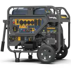
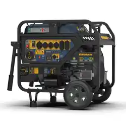
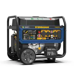
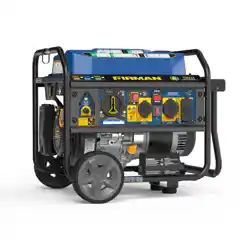
FIRMAN and logo design are trademarks or
registered trademarks of FIRMAN. All rights
reserved.
Serial Number
Purchase Date
MODEL #T04472
TRI-FUEL
PORTABLE GENERATOR
ATTACH YOUR RECEIPT
IMPORTANT, RETAIN FOR FUTURE REFERENCE: READ CAREFULLY
Thank you for purchasing this FIRMAN product.
Questions, problems or missing parts?
Before returning, contact us on:
844-347-6261, 8 a.m. - 8 p.m., EST, Monday - Sunday or
at www.rmanpowerequipment.com.
1
2
3
4
567
8
10
9

2
TABLE OF CONTENTS
Introduction.......................................................................................................................................................
Features, Controls and On-Product Hazard Labels...................................................................................
Operating Instructions.....................................................................................................................................
Maintenance - Storage....................................................................................................................................
Troubleshooting- Specications....................................................................................................................
Replacement Parts Lists .................................................................................................................................
Wiring Diagram ................................................................................................................................................
Service - Warranty ...........................................................................................................................................
3
7
13
31
37
39
45
46

3
Thank you for purchasing a FIRMAN generator. You have selected a high-quality, precision engineered
generator set designed and tested to give you years of satisfactory service. This generator is Tri-Fuel
and capable of running on gasoline, liquid petroleum gas (LPG), and natural gas (NG). This generator is
not intended to be run unattended or to supply power to life safety support.
This manual contains safety information to make you aware of the hazards and risks associated with
generator products and how to avoid them. This generator is designed and intended only for supplying
electrical power for operating compatible electrical lighting, appliances, tools and motor loads, and
is not intended for any other purpose. It is important that you read and understand these instructions
thoroughly before attempting to start or operate this portable generator. Save these original
instructions for future reference.
All information in this publication is based on the latest production information available at the time
of approval for printing. The manufacturer reserves the right to change, alter or otherwise improve the
generator and this documentation at anytime without prior notice.
INTRODUCTION

4
INTRODUCTION
SIGNAL WORDS
WARNING
Indicates a hazard
which, if not avoided,
could result in death
or serious injury.
DANGER
Indicates a hazard
which, if not avoided,
will result in death or
serious injury.
Safety Alert Symbol Indicates
a potential personal injury
hazard.
Operator's Manual - Failure to
follow warnings, instructions
and operator's manual could
result in death or serious injury.
Toxic Fumes - Engine exhaust
contains carbon monoxide, a
poisonous gas that will kill
you in minutes. You cannot
smell it or see it.
Generator could cause
electrical shock resulting in
death or serious injury.
Fire - Fuel and its vapors are
extremely ammable which
could cause burns or re
resulting in death or serious
injury. Engine exhaust could
cause re resulting in death
or serious injury.
Hot Surface - Muffler could
cause burns resulting in
serious injury.
CAUTION
Indicates a hazard
which, if not avoided,
could result in minor or
moderate injury.
NOTICE
Indicates information
considered Important,
but not hazard-related.

5
INTRODUCTION
WARNING! This product can expose you to chemicals including gasoline engine
exhaust, which is known to the State of California to cause cancer, and carbon
monoxide, which is known to the State of California to cause birth defects or other
reproductive harm. For more information go to www.P65Warnings.ca.gov.
This outdoor generator can be used to power outdoor items using extension cords.
NOTICE
If you have questions about intended use, contact FIRMAN customer service. This generator
is designed to be used only with FIRMAN authorized parts.
System Ground
The generator neutral is oating, which means that the AC stator winding is isolated from the
grounding fastener and the AC receptacle ground pins. On a oating neutral generator the AC
receptacle ground pins are not functional. Electrical devices, such as a ground fault circuit interrupter
(GFCI), requiring a functioning AC receptacle ground pin will not operate.
Compliance Requirements
There may be Federal or State regulations, local codes, or ordinances that apply to the intended
use of the generator. Consult a qualied electrician, electrical inspector, or the local agency having
jurisdiction. This generator is not intended to be used at a construction site or similar activity as
dened by NFPA 70-2023 (NEC) section 590.6.
To Restore Power Using Extension Cords

6
INTRODUCTION
1. Only use grounded cords marked for outdoor use rated for your loads.
2. Follow cord safety instructions.
3. Install carbon monoxide alarm(s).
4. When operating portable generator with extension cords, make sure portable generator is located
in an open, outdoor area, at least 20 ft downwind from occupied spaces with exhaust pointed away.
5. Extension cords running directly into your home, powering indoor items IS NOT RECOMMENDED.
Total
Amperage
Up to 13A
Up to 15A
Up to 20A
Up to 30A
Minimum Gauge, Outdoor Rated
Up to 50 ft
To provide power using
extension cords
16
14
12
10
DANGER! Engine exhaust contains carbon monoxide, a poisonous gas that will kill
you in minutes. You cannot smell it, see it, or taste it. Even if you do not smell
exhaust fumes, you could still be exposed to carbon monoxide gas.
● Extension cords running directly into the home increase your risk of carbon monoxide poisoning
through any openings.
● If an extension cord running directly into your home is used to power indoor items, the operator
recognizes that this increases the risk of CO poisoning to people inside the home and assumes
that risk.
*Certied by a Nationally Recognized Testing Laboratory that the product complies to appropriate
product safety test standards.

7
FEATURES, CONTROLS AND ON-PRODUCT HAZARD LABELS
1- Fuel Gauge
2- 5.0 Gallon Capacity Fuel Tank
3- Fuel Cap
4- Choke Lever(behind air lter box)
5- Air Filter
6- 223cc FIRMAN OHV Engine
7- Recoil Starter
8- 8.0 in Flat Free Wheel
9- Oil Filler Cap
10- Battery
11- Control Panel
12- Data Decal / Serial Number
*We are always working to improve our products. Therefore, the enclosed product may dier slightly
from the image on this page.
3 2
6
1
4
5
7
9
10
8
12
11
F

8
FEATURES, CONTROLS AND ON-PRODUCT HAZARD LABELS
Location and content of on-product hazard labels
FREE WARNING LABEL REPLACEMENT. If hazard labels become illegible or are missing, contact
FIRMAN customer service for a free replacement.
3
4
2
1
5
11
6
7
8
9
10

9
FEATURES, CONTROLS AND ON-PRODUCT HAZARD LABELS
1
2
3 4
5

10
FEATURES, CONTROLS AND ON-PRODUCT HAZARD LABELS
7
6
8
9
10
11

11
NOTICE
Total power drawn from all receptacles must not exceed the data decal rating.
1. LPG/NG Selector Switch – Select either LPG or NG.
2. LPG/NG Hose Connector (Inlet: 3/8 in Flare Male) – Used to connect LPG/NG hose to generator.
3. 3-1 Data-Minder (Multi-Meter) – Cycle through display the Voltage, Hertz and running hours.
4. Circuit Breakers – The receptacles are protected by AC circuit protectors. If the generator is
overloaded or an external short circuit occurs, a circuit protector may trip. If tripping occurs,
disconnect all electrical loads and determine the cause before attempting to continue using the
generator. Reset any tripped circuit protectors.
If multiple receptacles are used at the same time, the total current must be kept with-in the
portable generator data decal rating.
5. 120V, 20A Duplex - NEMA 5-20R(Not GFCI protected)
A maximum of 20 Amps current may be drawn from this duplex receptacle.
6. Ground Terminal – Consult an electrician or authority having jurisdiction for local grounding
requirements.
7. 120V, 30A – NEMA TT-30R (Not GFCI protected)
A maximum of 30 Amps current may be drawn from this receptacle.
8. 120V, 30A – NEMA L5-30R (Not GFCI protected)
A maximum of 30 Amps current may be drawn from this receptacle.
9. Engine Start Switch – To start engine, press and hold the switch in the START (ll) position, the
engine will crank and attempt to start. When the engine starts, release the switch to the RUN (l)
position.
FEATURES, CONTROLS AND ON-PRODUCT HAZARD LABELS
Control Panel
3
4
2
1
5
44
11
6
7
8
9
10
12

12
10.
CO Alert™ Carbon Monoxide (CO) Shutdown Indicator Light
— Indicates the engine shutdown
due to carbon monoxide accumulation around the generator or a CO Alert system fault occurred.
11.
Main Fuel Selector Switch/Engine Switch
– Use to select and turn on gasoline (GAS) or LPG/
NG fuel source. The GAS valve is closed when the switch is in the OFF or LPG/NG positions. Engine
switch is on when the switch is in GAS or LPG/NG positions.
12.
Indicator Light
– When the main fuel selector switch is turned to the GAS or LPG/NG position,
the indicator light will turn RED for up to 4 minutes (before going o). Starting the engine
successfully anytime during the 4 minutes will turn the indicator light GREEN. See Indicator
light-Battery Power Saving Mode section for more information.
FEATURES, CONTROLS AND ON-PRODUCT HAZARD LABELS

13
OPERATING INSTRUCTIONS
LOCATION
DANGER! Engine exhaust contains carbon monoxide, a poisonous gas that could
kill you in minutes. You CANNOT smell it, see it, or taste it. Even if you do not
smell exhaust fumes, you could still be exposed to carbon monoxide gas.
● Operate portable generator only outdoors, at least 20 ft downwind from occupied spaces with
exhaust pointed away to reduce the risk of carbon monoxide accumulating.
● Install battery-operated carbon monoxide alarms or plug-in carbon monoxide alarms with battery
back-up according to the manufacturer's instructions.
Smoke alarms cannot detect carbon monoxide gas.
● Do not run this portable generator inside homes, garages, basements, crawlspaces, sheds, or other
partially-enclosed spaces even if using fans or opening doors and windows for ventilation.
Carbon monoxide can quickly build up in these spaces and can linger for hours, even after this
product has shut o.
● If you start to feel sick, dizzy, weak or your home’s carbon monoxide alarm sounds, get to fresh air
right away. Call emergency services. You may have carbon monoxide poisoning.
A. Carbon Monoxide Alarm(s)
Install carbon monoxide alarms inside your home.
Without working carbon monoxide alarms, you
will not realize you are getting sick and dying from
carbon monoxide poisoning.
Prevent Carbon Monoxide (CO) Poisoning
Use outdoors at least 20 ft downwind from any home.
Point exhaust away from all homes and occupied spaces.
Install CO alarms inside your home.
20 ft min.
To better educate yourself about all carbon monoxide risks, go to
www.takeyourgeneratoroutside.com.
1

14
OPERATING INSTRUCTIONS
B
.
Reduce Risk of Fire
WARNING! Exhaust heat/gases could ignite combustibles, structures or damage
fuel tank causing a re, resulting in death or serious injury.
● Keep portable generator at least 5 ft from any structure, trees or vegetation over 12 in in height.
● Select an outdoor site that is dry and protected from the weather. Do not move portable generator
indoors to protect it from the weather.
● Do not locate the portable generator under a deck or other similar structure that may conne heat
and airow.
5 ft min.
5 ft min.
20 ft min.

15
OIL AND GASOLINE
2A. Add Engine Oil
Low Oil Shutdown
OPERATING INSTRUCTIONS
We recommend using SAE 10W-30 API SL or
higher oil for best performance. Do not use special
additives. Ambient temperature determines the
proper oil viscosity for the engine. Use the chart to
select the proper oil for the outdoor temperature
range expected.
NOTICE
Do not attempt to crank or start the
engine before it has been properly lled with the
recommended type and amount of oil. Damage
due to operation with no oil will void your warranty.
1. Place generator on a at, level surface.
2. Clean area around oil ll and remove yellow oil
ll cap/dipstick.
3. Wipe dipstick clean.
4. Using oil funnel, slowly pour contents of
provided oil bottle into oil ll opening until oil
reaches upper limit "H" mark on the dipstick.
Be careful not to overll. Overlling could cause
engine starting problems or engine damage.
5. Replace oil ll cap/dipstick and fully tighten.
6. Oil level should be checked prior to each use or
at least every 8 hours of operation.
Keep oil level maintained.
The portable generator is equipped with a low oil shutdown. If the oil level drops below the minimum
required level, a sensor will activate an internal switch stopping the engine. If the engine shuts o
and the oil level is within specications, check to see if generator is sitting at an angle. Place portable
generator on an even surface to correct this. If engine fails to start, the oil level may not be high
enough to deactivate the internal low oil level switch. Make sure the sump is completely full of oil to
the upper limit (H). Do not operate engine until oil level issue is corrected. Contact FIRMAN customer
service.
H
L
(H)
(L )
2
Degrees Celsiusº(Outside)
Full Synthetic 5W-30
5W-30
10W-30
10W-40
Degrees Fahrenheitº(Outside)

16
2B. Add Gasoline
OPERATING INSTRUCTIONS
WARNING! Fuel and its vapors are extremely ammable which could cause
burns or re resulting in death or serious injury.
● Turn generator engine OFF and let it cool at least 2 minutes before removing fuel cap.
● Do Not refuel or move generator when engine is running.
● Move generator outdoors prior to adding or draining fuel
● Keep fuel away from any ignition sources.
● Do not overll tank, allow space for fuel expansion.
● If any fuel spills, wait until it evaporates before starting engine
● Check and replace fuel lines, tank, cap, and ttings prior to each use if any damage or leaks are
found.
Fuel must meet these requirements:
● Clean, fresh, unleaded gasoline with a minimum
of 87 octane.
● Gasoline with no more than 10% ethanol is
acceptable.
E10 E15
NOTICE
Do not mix oil in gasoline or modify
engine to run on alternate fuels not described
in this manual. Use of unapproved fuels could
damage engine and will not be covered under
warranty.
1. Clean area around fuel ll cap, remove cap.
2. Slowly add unleaded fuel to fuel tank. Be careful
not to ll above the RED fuel level indicator.
This allows adequate space for fuel expansion.
3. Install fuel cap and let any spilled fuel evaporate
before starting engine.
Red Line
Indicator
Operation at High Altitude
At altitudes over 5,000 ft, a minimum 85 octane gasoline is acceptable.
Engine power and generator output will be reduced approximately 3.5% for every 1000 ft of elevation
above sea level. High altitude may cause hard starting, increased fuel consumption and sparkplug
fouling. To operate at high altitudes FIRMAN can provide a high altitude carburetor main jet. The
alternative main jet and installation instructions can be obtained by contacting Customer Support.
Altitude main jet 1
Altitude main jet 2
Altitude
3000-6000 ft
6000-8000 ft
NOTICE
Operation using an alternative main jet
at elevations lower than the recommended
minimum altitude can damage the engine. For
operation at lower elevations, the standard main
jet supplied must be used. Operating the engine
with the wrong main jet may increase exhaust
emissions, fuel consumption and reduce perfor-
mance.
223 cc
340717004
340717005

17
Operation at High Ambient conditions
Your FIRMAN Power Equipment product is designed and rated for continuous operation at ambient
temperatures up to 104°F. The generator may be operated at temperatures ranging from 5°F to 122°F
for short periods. If the generator is exposed to temperatures outside this range during storage, the
generator should be brought back within this range before operation. When operated above 77°F there
may be a decrease in power.
Maximum wattage and current are subject to and limited by such factors as ambient temperature,
altitude, engine conditions etc.
OPERATING INSTRUCTIONS
Connecting LPG/ NG Fuel
WARNING! Liquid Petroleum gas (LPG) and Natural Gas (NG) are extremely
ammable which could cause burns or re resulting in death or serious injury.
● The fuel supply line must always be shut o when the engine is not running. Failure to shut
o fuel may allow fuel to leak at the generator.
● Do not place the LPG/NG sources in the path of muer outlet or near any ignition source.
● Keep a re extinguisher near the generator all the time.
● Do not use or store LPG/NG portable sources not in use near generator or in a building, garage
or enclosed area.
● All LPG/NG supply/piping lines must be installed by a qualied plumber.
● If you smell gas, close o all gas sources and contact a qualied plumber to inspect and
repair the LPG or NG system.
● Prior to each days rst use spray a soapy water solution on LPG/NG fuel connections to check
for leaks.
● Never use a gas container, LPG/NG connector hose, LPG cylinder or NG source that appears
to be damaged.
● Do not connect or disconnect the LPG/NG source in an enclosed area.
● LPG is heavier than air and can accumulate in conned / low spaces if there is a leak.
NOTICE
If a fuel supply connection is necessary it must be installed in accordance with all local
codes or regulations, or in the absence of local codes or regulations, in accordance with the
National Fuel Gas Code (NFPA 54/ANSI Z223.1) and CSA B149.1 (Natural Gas and Propane
Installation Code), as applicable. If possible the fuel supply connection should be close to the
outdoor operating location. This will reduce the cost of the exible fuel run. An approved exible
fuel line must be installed between the generator LPG/NG Hose Connector (Inlet) and the fuel
supply connection. In no case should this information be interpreted to conict with any local,
state, or national code. If in doubt, always follow local codes.

18
● Always keep the LPG cylinder in an upright position.
● Use only DOT LPG cylinders in vapor service with type 1, right hand ACME threads. Verify the
re-qualication date on the cylinder has not expired.
● All new cylinders must be purged of air and moisture prior to lling. The purging process should be
done by your propane gas supplier.
Attach the LPG regulator hose assembly (included) to the LPG hose connector (inlet) on the control
panel of the generator. Tighten the nut with a 19 mm or adjustable wrench. Remove the safety plug
or cap from the LPG cylinder valve. Attach the LPG regulator to the cylinder valve. Do not use a
wrench to tighten LPG cylinder nut. Tighten the nut by hand clockwise to a positive stop. Using a
wrench may damage LPG cylinder components.
Connect the locally approved exible fuel supply line (not included) to the LPG/NG connector (inlet)
on the control panel and the fuel Source. We recommend you use FIRMAN 25 ft Quick Connect Hose
Kit (Model 1815) or 10 ft Quick Connect Hose Kit (Model 1805) for Natural Gas (NG) connection (This
item is not included). Hose requirements may vary in dierent regions depending on local codes.
Contact your local licensed plumber to ensure complete compliance with all codes. Make sure the
NG source location and hose used allows the portable generator to be located at least 20 ft from any
occupied spaces.
Indicator light - Battery Power Saving
This generator is equipped with an electronic module which consumes battery power. When the
main fuel selector switch is turned to the GAS or LPG/NG position, the indicator light will turn
RED for up to 4 minutes (before going o). Starting the engine successfully anytime during the 4
minutes will turn the indicator light GREEN. If portable generator is not started during this
4-minute period the portable generator will switch to Battery Power Saving Mode to conserve
battery life.
NOTICE
Your portable generator is equipped with an internal battery charger that will properly
charge the battery only when the engine is running.
The generator cannot be started in Battery Power Saving Mode. Turn main fuel selector switch to
the o position and back to the GAS or LPG/NG position to reset the RED indicator 4-minute
electronic module.
OPERATING INSTRUCTIONS

19
1. Before starting the generator, check for loose or
missing parts and for any damage which may
have occurred during shipment.
Ensure spark plug, muer, fuel cap, and air
cleaner are all in place.
2. Operate portable generator only outdoors and
downwind at least 20 ft from occupied
spaces with exhaust pointed away to reduce the
risk of carbon monoxide accumulating.
3. If connected make sure the LPG cylinder knob
or the NG source valve are fully closed or
disconnected.
4. Turn the main fuel selector switch to “GAS”
position.
NOTICE
When the main fuel selector switch is
turned to the GAS position, the indicator light will
turn RED for up to 4 minutes (before going o).
Starting the engine successfully anytime during
the 4 minutes will turn the indicator light GREEN.
See Indicator light-Battery Power Saving
Mode section for more information.
6. Move choke lever located on engine to “START”
position. You do not need to choke a warm engine.
(For electric start move to step (8))
3
4
6
WARNING! Failure to read and follow all warnings and instructions in this manual
and on-product labels before attempting to start or operate this portable generator
could result in death or serious injury.
Starting the Generator on Gasoline
3
5
5. Disconnect all electrical loads from the generator.
Never start or stop the generator with electrical
devices plugged in.
OPERATING INSTRUCTIONS

20
OPERATING INSTRUCTIONS
8
9
RUN
10. Allow portable generator to run at no load for
a few minutes to stabilize before plugging in any
electrical devices.
NOTICE
If engine starts but fails to run, or if
portable generator shuts down during operation,
check oil level. See Low Oil Shutdown section for
more information.
7. For recoil start only - Pull the starter cord slowly
until resistance is felt and then pull rapidly to
start engine.
7
8. For electric start only - Flip the engine switch to
the START (ll) position for a few seconds and
then release.
9. Do not over-choke. As soon as engine starts and
warms up, slowly move the choke lever to the RUN
position.

21
OPERATING INSTRUCTIONS
1. Before starting the generator, check for loose or
missing parts and for any damage which may
have occurred during shipment.
Ensure spark plug, muer, fuel cap, and air
cleaner are all in place.
2. Operate portable generator only outdoors and
downwind at least 20 ft from occupied
spaces with exhaust pointed away to reduce the
risk of carbon monoxide accumulating.
3. Connect the LPG hose with regulator to both
LPG cylinder and portable generator LPG/NG
Hose
4. Fully open the LPG cylinder knob.
6.Turn the LPG/NG selector switch to LPG.
3
4
Starting the Generator on LPG
4
5
6
5. Turn the main fuel selector switch to LPG/NG
position.
NOTICE
When the main fuel selector switch is
turned to the LPG/NG position, the indicator light
will turn RED for up to 4 minutes (before going o).
Starting the engine successfully anytime during
the 4 minutes will turn the indicator light GREEN.
See Indicator light-Battery Power Saving Mode
section for more information.

22
8
9
11
7
7. Disconnect all electrical loads from the generator.
Never start or stop the generator with electrical
devices plugged in.
8. Move choke lever located on engine to “START”
position. (For electric start move to step (12))
9. For recoil start only - PULL-TO-PRIME Pull the
starter cord 1-2 times. Pull slowly until resistance
is felt and then pull rapidly
.
11. For recoil start only - PULL-TO-RUN Pull the
starter cord slowly until resistance is felt and pull
rapidly to run the portable generator.
If the engine fails to start in 1-2 pulls with choke in
the RUN position, move choke lever to START
position and repeat the PULL-TO-PRIME step (9).
1-2 Times
10. For recoil start only - Move the choke lever to
the “RUN” position.
10
OPERATING INSTRUCTIONS

23
12
13
14
RUN
14. Allow portable generator to run at no load for
a few minutes to stabilize before plugging in any
electrical devices.
NOTICE
If engine starts but fails to run, or if
portable generator shuts down during operation,
check oil level. See Low Oil Shutdown section for
more information.
NOTICE
Observing frost on LPG cylinder and
regulator is common during operation and normally
is not an indication of a problem. In unusual
situations this frost may eventually restrict the
ow of LPG gas to the generator resulting in
deteriorating performance. In these rare situations
it can be helpful to:
● Exchanging fuel cylinders to allow the rst
cylinder to warm up, repeating as necessary.
● Placing the LPG cylinder at the end of the
generator near the handle, where engine fan air
ows out from the generator. This air is slightly
heated by air owing over the engine.
● Do not place the LPG cylinder in the path of the
muer exhaust outlet.
● The LPG cylinder and components can be
temporarily warmed by pouring warm water over
them.
12. For electric start only - Flip the engine switch to
the START (ll) position for a few seconds and
then release.
13. For electric start only - Move the choke lever to
the RUN position.
Muffler
OPERATING INSTRUCTIONS

24
1. Before starting the generator, check for loose or
missing parts and for any damage which may
have occurred during shipment.
Ensure spark plug, muer, fuel cap, and air
cleaner are all in place.
2. Operate portable generator only outdoors and
downwind at least 20 ft from occupied spaces with
exhaust pointed away to reduce the risk of carbon
monoxide accumulating.
3. Connect the NG hose to both the NG source and
portable generator LPG/NG Hose Connector
(inlet).
4. Fully open the NG source valve.
6.Turn the LPG/NG selector switch to NG
.
3
4
Starting the Generator on NG
5
5
6
5. Turn the main fuel selector switch to LPG/NG
position.
NOTICE
When the main fuel selector switch is
turned to the LPG/NG position, the indicator light
will turn RED for up to 4 minutes (before going o).
Starting the engine successfully anytime during
the 4 minutes will turn the indicator light GREEN.
See Indicator light-Battery Power Saving Mode
section for more information.
OPEN
OPERATING INSTRUCTIONS

25
8
9
11
7
7. Disconnect all electrical loads from the generator.
Never start or stop the generator with electrical
devices plugged in.
8. Move choke lever located on engine to “START”
position. (For electric start move to step (12))
9. For recoil start only - PULL-TO-PRIME Pull the
starter cord 1-2 times. Pull slowly until resistance
is felt and then pull rapidly
.
11. For recoil start only - PULL-TO-RUN Pull the
starter cord slowly until resistance is felt and pull
rapidly to run the portable generator.
If the engine fails to start in 1-2 pulls with choke in
the RUN position, move choke lever to START
position and repeat the PULL-TO-PRIME step (9).
1-2 Times
10. For recoil start only - Move the choke lever to
the “RUN” position.
10
OPERATING INSTRUCTIONS

26
OPERATING INSTRUCTIONS
12
13
RUN
14. Allow portable generator to run at no load for
a few minutes to stabilize before plugging in any
electrical devices.
NOTICE
If engine starts but fails to run, or if
portable generator shuts down during operation,
check oil level. See Low Oil Shutdown section for
more information.
12. For electric start only - Flip the engine switch to
the START (ll) position for a few seconds and
then release.
13. For electric start only - Move the choke lever to
the RUN position.

27
OPERATING INSTRUCTIONS
CONNECTING ELECTRICAL LOADS
6
Surge Protection
There is a remote chance that voltage uctuations may impair the proper functioning of some sensitive
electronic equipment. Electronic devices, including computers and many programmable appliances
may use components that are designed to operate within a narrow voltage range and may be aected
by the portable generator’s momentary voltage uctuations. While there is no way to prevent all voltage
uctuations, you can take steps to protect your sensitive electronic equipment. Install a plug-in surge
suppressor on the receptacles feeding your sensitive equipment. Surge suppressors come in single or
multi-outlet styles. They are designed to protect against short duration voltage uctuations.
1. Ensure circuit breaker on control panel is in the
closed (on) position.
2. Start the generator with no electrical load
attached.
3. Allow the engine to run for several minutes to
stabilize.
4. Plug in and turn on the rst item. It is best to
attach the item with the largest load rst.
5. Allow the engine to stabilize.
6. Plug in and turn on the next item.
7. Allow the engine to stabilize.
8. Repeat steps 5-6 for each additional item.
WARNING! Generator voltage could cause electrical shock or burn
resulting in death or serious injury.
● Damaged or overloaded extension cords could overheat, arc, and burn resulting death or serious
injury.
● Use a ground fault circuit interrupter (GFCI) in any damp or highly conductive area, such as metal
decking.
● Do not touch bare wires or receptacles.
● Do not use generator with electrical cords which are worn, frayed, bare or otherwise damaged.
● Do not operate generator in the rain or wet weather.
● Do not run indoors to avoid wet conditions.
● Do not handle generator or electrical cords while standing in water, while barefoot, or while
hands or feet are wet.

28
OPERATING INSTRUCTIONS
CO Alert
Carbon Monoxide (CO) Shutdown System
CO Alert automatically shuts down the engine when harmful levels of carbon monoxide accumulate
around the generator or a CO Alert fault occurs. After shutdown, the CO Alert indicator light will blink
for at least ve minutes per the chart below. CO Alert DOES NOT replace carbon monoxide alarms.
Install battery-powered carbon monoxide alarm(s) in your home. Don’t run generator in enclosed
areas.
*Yellow light will blink for ve seconds at the startup of generator to show CO ALERT is functioning
properly.
Color
RED
Yellow
Carbon monoxide accumulated around generator. Prior to restart move
generator to an open, outdoor area 20 ft downwind from occupied
spaces with exhaust pointed away. Air out premises (open windows
and doors) before reoccupying property. Automatic shuto is an
indication generator was improperly located.
If you start to feel sick, dizzy, weak, or your homes carbon monoxide
alarm sounds while using this product, get to fresh air right away. Call
emergency services. You may have carbon monoxide poisoning.
CO Alert fault occured*.
See FIRMAN authorized service dealer.
Description

29
OPERATING INSTRUCTIONS
STOPPING THE GENERATOR
7
1. Turn o and remove all electrical loads.
Never stop the generator with electrical devices
plugged in and turned on.
Never stop the engine by moving the choke to the
start position.
2. Turn the engine switch to OFF (O) position
.
4. Fully close the LPG cylinder knob and NG
source valve.
If a cover is used, do not install until unit has
cooled.
Let the generator run at no-load for one minute to
stabilize internal temperatures of the engine and
generator.
1
2
4
3. Turn the main fuel selector switch to OFF (O)
position.
3

30
To be performed by knowledgable/experienced owner or by authorized service center.
General Recommendations
Regular maintenance will improve the performance and extend the life of the generator. See any
authorized dealer for service.
The generator's warranty does not cover items that have been subjected to operator abuse or
negligence. To receive full value from the warranty, the operator must maintain the generator as
instructed in this manual.
Some adjustments will need to be made periodically to properly maintain your generator.
All service and adjustments should be made at least once each season. Follow the requirements in the
maintenance shedule chart above.
NOTICE
Once a year you should clean or replace the spark plug and replace the air lter. New
spark plug and clean air lter assure proper fuel-air mixture and help your engine run at peak
performance and last longer.
MAINTENANCE SCHEDULE
Check condition. Adjust gap
and clean. Replace if necessary.
Clean fuel tank strainer.
Replace if necessary.
Check fuel hose for cracks or other
damage. Replace if necessary.
Check for leakage. Retighten or
replace gasket if necessary.
Check spark arrester screen.
Clean/Replace if necessary.
Clean, replace if necessary.
Check adjust valve clearance.
Clean combustion chamber.
Check. Replace if necessary.
Check oil level.
Replace.
√
√
Daily
(Before
operation)
Initial
25
hours
Every
50
hours
Every
250
hours
Every
100 hours
(or annual)
√
√
√
√
√
√
√
√
√
MAINTENANCE - STORAGE
NOTES
ITEM
Fittings/
Fasteners
Exhaust
System
Fuel Line
Air Filter
Engine Oil
Spark Plug
Fuel
Engine
√
LPG Regulator
/Hose Assy.
Check for damage and leaks.
Replace if necessary.
√

31
When Transporting Generator
Transport with fuel tank EMPTY or with fuel valve in OFF position.
Do not tip generator at an angle which causes fuel to spill.
Disconnect LPG/ NG fuel hose and securely stow away.
Engine Maintenance
To prevent accidental starting, remove and ground spark plug wire before performing any service.
Change Engine Oil
Change engine oil every 100 hours (for a new engine, change oil after 25 hours). If you are using your
generator under extremely dirty or dusty conditions, or in extremely hot weather change the oil more
often.
CAUTION!
Avoid prolonged or repeated skin contact with used motor oil. Used motor oil has been
shown to cause skin cancer in certain laboratory animals. Thoroughly wash exposed areas with soap
and water.
MAINTENANCE - STORAGE
(a) On a level surface drain oil into a suitable
container by removing the drain plug and the oil
ller cap while the engine is warm.
(b) Reinstall the drain plug and ll the engine with
oil until it reaches the HIGH(H) level on the oil
ller dipstick.
NOTICE
We recommend using SAE 10W-30 API
SL or higher oil for best performance. Do not use
special additives. See Oil and Gasoline section
(page 15).
Keep Out Of Reach Of Children. Don’t
Pollute. Conserve Resources. Return
Used Oil To Collection Centers.
(H)
(L )

32
MAINTENANCE - STORAGE
Air Filter Maintenance
(a) Carefully remove foam air lter element and
wash it with liquid detergent and water only.
Squeeze dry in a clean cloth.
Air Filter Element
(c) Reinstall clean or new air lter element.
(b) Saturate foam air lter element with clean
engine oil and squeeze in a clean cloth to remove
excess oil.

33
MAINTENANCE - STORAGE
Spark Plug Maintenance
Muer and Spark Arrester Maintenance
Changing the spark plug will help your engine start
easier and run at peak performance.
(a) Remove the spark plug boot.
(b) Remove spark plug using provided wrench.
(c) Inspect spark plug for damage and clean with a
wire brush before reinstalling. Replace if damaged.
(d) Adjust the electrode gap to 0.020 - 0.024 in.
(e) Seat spark plug in position and thread by hand to
prevent cross threading.
(f) Tighten plug with provided wrench and put the
spark plug boot back on spark plug.
Maintenance Valve Clearance
Intake: 0.004 – 0.006 in
Exhaust: 0.004 – 0.006 in
Spark Plug: FIRMAN P/N 330723001,
CHAMPION N9YC or Equivalent.
● Do not touch hot parts.
● It is a violation of California Public Resource Code, Section 4442, to use or operate the engine on
any forest covered, brush-covered, or grass-covered land unless the exhaust system is equipped
with a spark arrester, as dened in Section 4442, maintained in eective working order. Other states
or federal jurisdictions may have similar laws, reference Federal Regulation 36 CFR Part 261.52.
WARNING!
Contact with muer area could cause burns resulting in serious injury.
0.020-0.024 in

34
MAINTENANCE - STORAGE
Inspect Muer and Spark Arrester
1. Inspect the muer for cracks, corrosion, or other
damage.
2. Remove the spark arrester screws, ange and
screen with a screwdriver.
3. Carefully remove the carbon deposits from the
spark arrester screen with a wire brush.
4. Replace the spark arrester if it is damaged. If
replacement parts are required, make sure to use
only FIRMAN original equipment replacement
parts.
5. Position the spark arrester on the muer and
attach spark arrester ange with the screws.
NOTICE
Failure to clean or replace spark arrester
may result in decreased engine performance.
Spark arrester
screen
Flange
Screw

35
MAINTENANCE - STORAGE
Battery Maintenance
Battery Charging
A(M6X12)
1. Remove the spark plug wire from spark plug.
2. Remove the nut and bolt from the negative(-) and
positive(+) posts.
3. Loosen and remove the screw A on the battery
holding bracket.
4. Remove the battery and recycle.
5. Install the new battery with following specication:
12V sealed lead acid 7.5AH
LXWXH: 5.95X2.55X3.82 in.
6. Connect the red positive(+) battery cable to
the battery rst.
7. Connect the black positive(-) battery cable
to the battery second.
8. Cover the posts with boots.
9. Install the spark plug wire onto spark plug.
The battery powers the starter motor and control module. This portable generator is equipped with an
automatic battery charging circuit. The battery will receive charging voltage only when the engine is
running. The battery will maintain a proper charge if the portable generator is used on a regular basis
(about once every two weeks). If it is used less frequently, the battery should be connected to a trickle
charger (not included) or battery maintainer (not included) to keep the battery properly charged. If the
battery is not able to start the engine, it can be started manually only in the GAS position by pulling the
engine recoil cord. If the battery voltage is extremely low, the charging circuit may not be able to re-
charge the battery. In this case, the battery must be connected to a standard automotive style battery
charger for recharging before it can be used.

36
MAINTENANCE - STORAGE
GENERATOR MAINTENANCE
● Run the generator at least 30 minutes every month.
● Make certain that the portable generator is kept clean and dry.
● Do not expose the unit to excessive dust, dirt, moisture or corrosive vapors.
● Do not insert any objects through cooling slots.
● Before each use inspect underneath the generator for signs of oil or fuel. Clean any accumulated
debris. Keep area around muer free from any debris. Use a soft bristle brush to remove dirt or caked
on oil. Use a damp cloth to clean all exterior surfaces.
Long Term Storage
It is important to prevent gum deposits from forming in essential fuel system components such as
the carburetor, fuel hoses or tank during storage. Ethanol-blended fuels (called gasohol, ethanol or
methanol) attract moisture, which leads to separation and formation of acids during storage.Acidic gas
can damage the fuel system of an engine while in storage.
When the generator set is being stored for more than one month, follow these instructions to avoid
engine problems:
WARNING!
Fuel and its vapors are extremely
ammable which could cause burns or
re resulting in death or serious injury.
Do not store fuel near any ignition sources.
When draining fuel move generator outdoors and use a
commercially available non-conductive vacuum siphon.
Fuel must be drained into an approved container.
1.Add a properly formulated fuel stabilizer to the gasoline
tank.
2.Start the generator as instructed in Starting the
Generator section.
3.Run the generator for 5-10 minutes so the treated
gasoline cycles through the fuel system.
4.Turn the main fuel selector switch to the “STORAGE
OFF” position until the engine stops. This may take 3-5
minutes. Then turn the fuel selector switch to “OFF(O)”
position.
5.Change oil after the engine cools down entirely.
6.Remove spark plug and pour about one teaspoon of
engine oil into the cylinder.
7.Pull the starter cord a few times to lubricate the cylinder
and then reinstall the spark plug.
8.Cover and store the unit in a clean, dry place out of
direct sunlight.
NOTICE
Any damage or hazards caused by using
improper fuel, improperly stored fuel, and/or improperly
formulated stabilizers, are not covered by manufacturer's
warranty.
Do not store gasoline from one season to another
season.
STORAGE OFF

37
TROUBLESHOOTING – SPECIFICATIONS
Problem Cause Correction
Engine is running,
but no AC output is
available.
1. Circuit breaker is open.
2. Fault in generator.
3. Poor connection or defective cord
set.
4. Connected device is bad.
1. Reset circuit breaker.
2. Contact authorized service facility.
3. Check and repair.
4. Connect another device that is in
good condition.
Engine runs
good at no-load
but “bogs down”
when loads are
connected.
1. Short circuit in a connected load.
2. Engine speed is too slow.
3. Generator is overloaded.
4. Shorted generator circuit.
5. Clogged or dirty fuel lter.
1. Disconnect shorted electrical load.
2. Contact authorized service facility.
3. See Don’t Overload Generator.
4. Contact authorized service facility.
5. Clean or replace fuel lter.
Engine will not
start; starts and
runs rough or
shuts down when
running.
1. Fuel selector switch set to OFF
(O)position.
2. The indicator light is OFF or
ashing red.
3. Low oil level.
4. Dirty air cleaner.
5. Out of fuel.
6. Stale fuel.
7. Spark plug wire not connected to
spark plug.
8. Bad spark plug.
9. Water in fuel.
10. Flooded.
11. Excessively rich fuel mixture.
12. Clogged or dirty fuel lter.
13. Starting battery may have
insucient charge.
14. Out of LPG/NG.
15. LPG cylinder knob / NG supply
valve is not open.
16. Out of battery power.
1. Set fuel selector switch to “GAS”
or “LPG/NG” position.
2. Must have solid red indicator light
to be able to start the engine.
3. Fill crankcase to proper level or
place generator on level surface.
4. Clean or replace air cleaner.
5. Fill fuel tank.
6.
Drain fuel tank and carburetor; ll with fresh fuel.
7. Connect wire to spark plug.
8. Replace spark plug.
9.
Drain fuel tank and carburetor; ll with fresh fuel.
10.
Wait 5 minutes and re-crank engine.
11. Contact authorized service facility.
12. Clean or replace fuel lter.
13. Check battery output and charge
battery as necessary.
14.
Replace LPG cylinder/ check NG supply.
15. Fully open LPG cylinder knob / NG
supply valve.
16. Start Engine in “GAS” position.
Charge or replace battery.
Engine lacks
power.
1. Load is too high.
2. Dirty air lter.
3. Clogged or dirty fuel lter.
4. Clogged spark arrester.
1. Don’t Overload Generator
2. Replace air lter.
3. Clean or replace fuel lter.
4. Clean or replace spark arrester.
Engine “hunts”
or falters.
1.
Carburetor is running too rich or too lean.
2. Clogged or dirty fuel lter.
1. Contact authorized service facility.
2. Clean or replace fuel lter.
Engine shuts down
when running.
1. Out of gasoline or LPG/NG
2. Dirty air cleaner.
3. Low oil level.
1. Fill fuel tank with gasoline or replace
LPG cylinder / check NG supply.
2. Clean or replace air cleaner.
3. Fill crankcase to proper level or
place generator on level surface.
Engine shuts down
and yellow CO
fault light blinking.
1. CO system fault 1. Contact authorized FIRMAN
service facility.
For all other issues, contact authorized dealer or FIRMAN customer service.

38
TROUBLESHOOTING – SPECIFICATIONS
Model
Starting Watts
Running Watts*
Rated AC Voltage
Rated Fequency
Phase
Voltage Regulator
Power Factor
Alternator Type
Engine
Engine Type
Displacement
Low Oil Shutdown
Ignition System
Starting System
Fuel
Capacity Fuel Tank
Lubricating Oil Capacity
Carburetor Type
Air Cleaner
P.T.O. Shaft Rotation
Oil Type
AC Grounding System
Natural Gas Fuel Pressure Range
Natural Gas Fuel Consumption
LPG fuel consumption
T04472
5500(GASOLINE)/4950(LPG)/4400(NG)
4400(GASOLINE)/3950(LPG)/3500(NG)
120V
60Hz
Single
AVR
1
Brushed
FIRMAN
Single Cylinder, 4-Stroke OHV Air Cooled
223cc
Yes
Breakless Ignition Type, Flywheel Magneto
Recoil/Electric
Unleaded Automotive Gasoline/LPG/NG
19 L / 5 gallons
600 ml / 20.3 oz
Float
Polyurethane Type
Counter Clockwise (Facing P.T.O.)
See “Add Engine Oil” Section
Neutral Floating
1.7-2.7 kpa / 13- 20mm mercury
7-11 inches water column / 0.25-0.40 psi
*Generator certied in accordance with CSA (Canadian Standards Association) standard C22.2No.
100-14,Motors and Generators and complies with PGMA (Portable Generator Manufacturers’
Association) standard ANSI/PGMA G300-2023, Safety and Performance of Portable Generators.
Specications
Quarter Load (25%) Half Load (50%) Full Load (100%)
0.8 m
3
/h
28.25 ft
3
/h
29,097 BTU/h
8,527 W
1.64 m
3
/hr
58 ft
3
/hr
58,764 BTU/h
17,218 W
38.1 MJ/h
36,134 BTU/h
10,593 W
46.2 MJ/h
43,750 BTU/h
12,822 W
71.7 MJ/h
67,733 BTU/h
19,845 W
1.2 m
3
/h
42.4 ft
3
/h
43,958 BTU/h
12,884 W

REPLACEMENT PARTS LIST
T04472 Parts Diagram
For replacement parts, call our customer service department at 844-347-6261, 8 a.m. - 8 p.m., EST, Monday - Sunday.
40

REPLACEMENT PARTS LIST
223cc Engine Parts Diagram
41
26
1
2
3
4
5
6
7
8
9
10
11
12
13
14
15
16
17
18
19
20
21
22
23
24
25
26
27
28
29
30
31
32
33
34
35
36
37
38
39
40
41
42
43
44
45
46
47
48
49
50
51
52
54
55
56
57
58
59
60
61
62
63
64
65
66
67
68
69
70
71
72
73
74
75
76
77
78
79
80
81
82
83
84
85
86
87
88
89
90
91
93
94
95
96
21
83
85
87
44
51
92

41
REPLACEMENT PARTS LIST
T04472 Portable Generator
All replacement parts are covered under warranty.
NO.
Part
Number
Description Qty.
1
340465000
Engine Assy.
1
2 336713501
Rubber Cap 2
1
3 336713502
Rubber Cap 1
1
4 340453006
Rotor And Stator Set
1
4.1 340453002
Rotor
1
4.2 340453001
Stator
1
4.3 340713001
Stator Cover
1
5 336713506
Generator End Cover
1
6 336718303
Flange Bolt M5 x 12
1
7 336713508
Flange Bolt M8 x 252
1
8 336713511
Flange Bolt M6 x 179
4
9 336713514
Ground Wire
1
10 336718301
Flange Bolt M6 x 12
3
11 336713516
External Teeth Lock Washer
1
12 336718326
Nut M6
1
13 340755500
AVR
1
14 336713519
Flange Bolt M5 x 16
2
15 336713520
Bolt & Washer Assy. M5 x 16
2
16 336715514
Generator End Cover Cap
1
17 336718309
Flange Bolt M5 x 12
2
18 336713522
Ground Wire
1
19 336713523
Terminal Block
1
20 336713524
Flange Bolt M5 x 16 & Washer
1
21 357713511
Lock Washer Ø5
1
22 336713525
Carbon Brush Holder
1
23 336713526
Carbon Brush Assy.
1
24 340455013
Control Panel Assy.
1
25 340415008
Wheel Kit
1
26 336717015
Nut M8
2
27 336713509
Lock Washer Ø8
2
28 336713533
Flat Washer Ø8
2
29 340415002
Mufer
1
30 336717014
Gasket, Mufer
1
31 340715001
Mufer Support
1
32 336413509
Support Leg Assy.
1
32.1 336713557
Rubber Support
2
32.2 336718326
Nut M6
2
32.3 336713561
Flange Bolt M6 x 25
2
32.4 336713560
Support Leg
1
33 336713559
Flange Bolt M8 x 16
2
34 336718315
Nut M8
2
35 336715506
Axle Pin
2
36 355728326
Wheel
2
37 336713510
Flat Washer Ø8
2
38 336713556
Cotter Pin
2
39 363723007
Plug, Wheel
2
40 330713508
Clip Ø10.5 x 8
4
41 340725002
Fuel Hose
1
42
336713807
Tank Fitting With Filter
1
NO.
Part
Number
Description Qty.
43
340715004
Fuel Tank
1
44 336713542
Grommet, Fuel Tank
4
45 357713600
Bushing
4
46 336713548
Fuel Filter, Wire Mesh
1
47 336713007
Fuel Gauge Assy.
1
48 336417031
Screw M5 x 16
2
49 399715513
Fuel Gauge Display
1
50 310715064
Bolt M6 x 20
4
51 336713549
Fuel Cap
1
52 317713553
Clamp Ø8 x 6
1
53 340725016
Hose
1
54 375715021
Clip Ø8.8 x 8
1
55 336718318
Nut M8
4
56 340415004
Frame Assy.
1
56.1 336713562
Isolator 1
2
56.2 336713563
Isolator 2
2
56.3 336718318
Nut M8
4
56.4 340715005
Frame
1
56.5 336718304
Generator Protection Bracket
1
56.6 336718301
Flange Bolt M6 x 12
1
56.7 336718326
Nut M6
1
56.8 340715002
Bolt M8 x 70
2
56.9 340725015
Handle Cap
2
56.10
340715048
Nut M8
2
56.11 340715003
Handle
1
56.12 340725003
Handle Cover
1
57 336718302
Flange Bolt M6 x 12
7
58 336718318
Nut M8
2
59 336718305
Flange Bolt M8 x 35
2
60 393728308
Flange Nut M5
2
61 357713569
Screw & Washer Assy. M5 x 10
2
62 336713814
Battery, 12V, 7.5Ah
1
63 336718302
Flange Bolt M6 x 12
2
64 336713645
Bracket, Battery
1
65
333755502
Battery Wire
1
66 336713611
Boot, Rubber Battery
1
67 336713693
Battery Cable, Negative, Female, 180mm
1
68 336713692
Battery Cable, Negative, Male, 120mm
1
69 357713571
Boot, Black Battery
1
70 357713570
Boot, Red Battery
1
71 317713521
Screw ST4.8 x 17
1
72 332753001
CO Module
1
73 340725004
Control Box
1
74 340755001
Control Module
1
75 355418316
Fuel Valve
1
76 360715518
Screw & Washer Assy. M5 x 16
2
77 336713569
Screw & Washer Assy. M4 x 8
6
78 344755001
Breaker, 36A Push Button Circuit
1
79 317713580
Receptacle, L5-30R
1

42
NO.
Part
Number
Description Qty.
80
340415005
Main Regulator Assy.
1
81 340455001
Control Panel
1
82 336718383
Screw & Washer Assy. M4 x 14
9
83 363753004
Multimeter
1
84 336713828
Indicator Light
1
85 340725005
Fuel Selector Switch
1
86 336755002
CO Indicator Light
1
87 340725503
Switch Cover
1
88 336725506
Receptacle Cover, L5-30R
1
89 336725507
Cover, Receptacle TT-30R
1
90 336725508
Receptacle Cover, 5-20R
1
91
357713542
Flange Bolt M6 x 22
1
92 380713515
Nut M6
2
93 336713512
Lock Washer Ø6
2
94 336713513
Flat Washer Ø6
2
95 336713516
External Teeth Lock Washer Ø6
1
96 399755662
Switch, Electric Start
1
97 336755005
Cover, 20A Push Button Circuit
3
98 336457020
Nut
3
99 336713826
LPG Inlet Cover
1
100 336713584
Receptacle, TT-30R
1
101 330713607
Receptacle, 5-20R Duplex
1
102 336718324
Nut M4
8
103 336713586
Circuit Breaker, 30A
1
104 336713585
Circuit Breaker, Push Button, 20A
1
105 336713818
Charging Module
1
106 357713545
Grommet
1
107 340725006
Sleeve
1
108 340725507
Grommet
1
109 336713835
Clamp Ø8-Ø14
2
110 375715034
LPG Hose
1
111 340725007
Fuel Hose
1
112 360418309
LPG Regulator/Hose Assy.
1
113 340415006
Fuel Tank Assy.
1
114 340415007
Mufer Assy.
1
REPLACEMENT PARTS LIST
NO.
Part
Number
Description Qty.

43
223cc Engine
REPLACEMENT PARTS LIST
NO.
Part
Number
Description Qty.
1
336715522
Flange Bolt M6 x 16
3
2 335425587
Recoil Assy.
1
3 330713555
Nut M14
1
4 336723581
Pulley, Starter
1
5 336723575
Bracket, Recoil Mounting
1
6 336723606
Clamp
2
7 336718302
Flange Bolt M6 x 12
4
8 340715007
Engine Cover Assy.
1
9 336723582
Cooling Fan
1
10 340713017
Flywheel
1
11 336723514
Flange Bolt M8 x 32
6
12 336723513
Seal, Oil
2
13 336723512
Cover, Crankcase
1
14 336723511
Oil Dipstick Assy.
1
15 336723598
Bushing, Govorner Gear
1
16 336723597
Clip, Govorner Gear
1
17 336723596
Gear, Governor
1
18 336723594
Governor, Gear Shaft
1
19 336723595
Inner Washer, Gear
1
20 317723516
Dowel Pin 8 x 14
2
21 336723510
Gasket, Crankcase
1
22 336718301
Flange Bolt M6 x 12
2
23 340718300
Sensor, Engine Oil
1
24 336418301
Crankcase Assy.
1
25 336723507
Woodruff Key
1
26 336723505
Bearing 6205
2
27 340713007
Crankcase Subassy.
1
28 336723546
Bolt, Drain Plug
2
29 336723545
Washer, Drain Bolt
2
30 336723610
Pin Ø8 x 10
2
31 336723612
Sheath, Wire
1
32 336723611
Air Guide, Right Side
1
33 336723574
Flange Bolt M6 x 25
1
34 336723609
Flange Bolt M6 x 29
1
35 336718311
Flange Bolt M6 x 29
2
36 336715520
Ignition Coil
1
37 340713010
Rod, Connecting
1
38 336723517
Pin, Piston
1
39 336723516
Piston Pin Retaining Ring
2
40 336723519
Ring, Oil
1
41 336723520
Ring, Second Piston
1
42 336723521
Ring, First Piston
1
43 336723518
Piston
1
44 340728300
Gasket, Cylinder Head
1
45 330723548
Locating Pins
2
46 340715509
Cylinder Head
1
47
336467007
Exhaust Valves Stud Bolt
2
48
330723001
Spark Plug, F7TC
1
NO.
Part
Number
Description Qty.
49
336723527
Flange Bolt M8 x 55
4
50 340713011
Cylinder Head Air Guide
1
51 336723524
Gasket, Cylinder Head Cover
1
52 336723525
Cover, OHV
1
53 336723526
Flange Bolt M6 x 15
4
54 340713008
Camshaft Assy.
1
55 340718301
Tappet, Valve
2
56 340718302
Push Rod
2
57 336723537
Bolt, Valve Adjusting
2
58 336723538
Guide Plate, Push Rod
1
59 336723531
Valve, Rocker
2
60 336723529
Nut, Valve Adjusting
2
61 336723528
Nut, Valve Lock
2
62 336723541
Valve, Intake
1
63 336723542
Valve, Exhaust
1
64 336723536
Oil Seal, Valve
2
65 336723535
Spring, Valve
2
66 336723533
Retainer, Intake Valve
1
67 340718303
Retainer, Exhaust Valve
1
68 336723532
Rotator, Exhaust Valve
1
69 336723614
Starter Motor Assy.
1
69.1 336713519
Flange Bolt M5 x 16
2
69.2 340718307
Solenoid, Starter
1
69.3 340718308
Starter Motor
1
70 336723563
Shaft, Governor Arm
1
71 336713590
Pin, Shaft
1
72 336723564
Rocker Shim
1
73 336723555
Nut M6
1
74 340718304
Governor Arm
1
75 336723567
Bolt, Governor Arm
1
76 336718310
Spring, Governor
1
77 336723569
Rod, Governor
1
78 336723570
Spring, Throttle Valve
1
79 340418303
Governor Assy.
1
80 336718301
Flange Bolt M6 x 12
2
81 336723530
Breather Tube
1
82 336723549
Stud, Intake
2
83 336723550
Gasket, Insulator
1
84 340713012
Plate, Carburetor Insulator
1
85 340713013
Gasket, Carburetor
1
86 340715008
Carburetor
1
87 336725530
Gasket, Air Cleaner
2
88 336723555
Nut M6
2
89 336718308
Flange Bolt M6 x 8
1
90 336713527
Air Cleaner Bracket
1
91 336423502
Air Cleaner Assy.
1
91.1
336723557
Elbow, Air Cleaner
1
91.2
336728302
Gasket, Air Cleaner Rubber
1

44
REPLACEMENT PARTS LIST
NO.
Part
Number
Description Qty.
91.3
336723558
Clapboard
1
91.4 336723559
Mounting Bolt, Air Cleaner
4
91.5 336723560
Element, Air Cleaner
1
91.6
336723561
Cover, Air Cleaner
1
92 340418305
Cover, Rotor Fan Crankcase
1
93 336423504
Piston Ring Set
1
94
340415502
Cylinder Head Assy.
1
95 340415503
Gasket Set
1
96 330723528
Wire Clip
1
NO.
Part
Number
Description Qty.

45
WIRING DIAGRAM
Wiring Diagram
36.6A

46
SERVICE – WARRANTY
For service information contact FRIMAN customer service at 1-844-347-6261 or at www.
rmanpowerequipment.com to obtain warranty service information or to order replacement
parts or accessories.
HOW TO ORDER REPLACEMENT PARTS
Even quality-built equipment such as this electric generator may need occasional
replacement parts to maintain it in good condition over the years. To order replacement parts,
please give the following information:
● Model No. Rev. Level and Serial No. found on the Data Decal.
● Parts number or numbers as shown in the Parts List section.
● A brief description of the trouble with the generator.
FIRMAN 3 YEARS LIMITED WARRANTY
Repair/Replacement Warranty
FIRMAN warrants to the original purchaser that the mechanical and electrical components will be
free of defects in material and workmanship for a period of one (1) year (parts and labor) and 3 years
(parts and technical support) from the original date of purchase 90 days [parts and labor] and 180
days [parts] for commercial & industrial use. Transportation charges on product submitted for
repair or replacement under this warranty are the sole responsibility of the purchaser . This warranty
only applies to the original purchaser and is not transferable.
Do Not Return the Unit to the Place of Purchase
Contact the FIRMAN customer service and FIRMAN will troubleshoot any issue via phone or e-mail.
If the problem is not corrected by this method, FIRMAN will, at its option, authorize evaluation,
repair or replacement of the defective part or component at a FIRMAN Service Center. FIRMAN
will provide you with a case number for warranty service. Please keep it for future reference.
Repairs or replacements without prior authorization, or at an unauthorized repair facility, will not be
covered by this warranty.
Warranty Exclusions
This warranty does not cover the following repairs and equipment.
Normal Wear
Your product needs periodic parts and service to perform well. This warranty does not cover repair
when normal use has exhausted the life of a part or the equipment as a whole.
Warranty Qualications
Register your product using the QR code provided or at www.
rmanpowerequipment.com.FIRMAN will also register the warranty upon
receipt of your Warranty Registration Card and acopy of your sales receipt
from one of FIRMAN’s retail locations as proof of purchase. Pleasesubmit
your warranty registration and your proof of purchase within ten(10) days of
the date ofpurchase.

47
SERVICE – WARRANTY
INSTALLATION, USE AND MAINTENANCE
This warranty will not apply to parts and/or labor if your product is deemed to have been misused,
neglected, involved in an accident, abused, loaded beyond the generator’s limits, modied,
installed improperly or connected incorrectly to any electrical component. Normal maintenance is
not covered by this warranty.
Other Exclusions
This warranty excludes:
– cosmetic defects such as paint, decals, etc.
– wear items
– accessory parts
– failures due to acts of God and other force majeure events beyond the manufacturer’s control
– problems caused by parts that are not original FIRMAN parts
– units used for prime power in place of existing utility power where utility is present or in place
of utility power where utility power service does not normally exist.
LIMITS OF IMPLIED WARRANTY AND CONSEQUENTIAL DAMAGE
FIRMAN disclaims any obligation to cover any loss of time, use of this product, freight, or any
incidental or consequential claim by anyone from using this product. THIS WARRANTY IS IN LIEU OF
ALL OTHER WARRANTIES, EXPRESS OR IMPLIED, INCLUDING WARRANTIES OF MERCHANT
ABLILITY OR FITNESS FOR A PARTICULAR PURPOSE.
A unit provided as an exchange will be subject to the warranty of the original unit. The length of the
warranty governing the exchanged unit will remain calculated by reference to the purchase date of the
original unit.
This warranty gives you certain legal rights which may change from state to state. Your state may
also have other rights you may be entitled to that are not listed within this warranty.
Contact Information
You may contact FIRMAN at:
Firman Power Equipment Inc.
Attn: Customer Service
8644 W. Ludlow Dr.
Peoria, AZ 85381
www.rmanpowerequipment.com
We are FIRMAN POWER - And we are here for you.

48
SERVICE – WARRANTY
CALIFORNIA AND FEDERAL EXHAUST AND EVAPORATIVE EMISSIONS CONTROL WARRANTY
STATEMENT
YOUR WARRANTY RIGHTS AND OBLIGATIONS
The California Air Resources Board, US Environmental Protection Agency (“US EPA”) and FIRMAN
POWER EQUIPMENT INC.(FIRMAN) are pleased to explain the emissions control systems warranty
on your 2025-2026 or later Small O-Road Engine (“SORE”) and engine powered equipment. In
California, new equipment that use small o-road engines must be designed, built and equipped to
meet the State’s stringent anti-smog standards. FIRMAN must warrant the emissions control systems
on your SORE and engine powered equipment for the periods of time listed below provided there has
been no abuse, neglect or improper maintenance of your small o-road engine or equipment leading
to the failure of the emissions control system.
Your emissions control system may include parts such as the carburetor or fuel-injection system, the
ignition system, catalytic converter, fuel tanks, fuel lines (for liquid fuel and fuel vapors), fuel caps,
valves, canisters, lters, clamps and other associated components. Also included may be hoses,
belts, connectors, and other emission-related assemblies.
Where a warrantable condition exists, FIRMAN will repair your SORE and engine powered equipment
at no cost to you including diagnosis, parts and labor.
MANUFACTURER’S WARRANTY COVERAGE:
The exhaust and evaporative emissions control system on your small o-road engine and engine
powered equipment is warranted for two years. If any emissions-related part on your small o-road
engine and engine powered equipment is defective, the part will be repaired or replaced by FIRMAN.
OWNER’S WARRANTY RESPONSIBILITIES:
As the SORE and engine powered equipment owner, you are responsible for the performance of
the required maintenance listed in your operator’s manual. FIRMAN recommends that you retain all
receipts covering maintenance on your SORE and engine powered equipment, but FIRMAN cannot
deny warranty coverage solely for the lack of receipts or for your failure to ensure the performance of
all scheduled maintenance.
As the SORE and engine powered equipment owner, you should however be aware that FIRMAN may
deny you warranty coverage if your small o-road engine or engine powered equipment or a part has
failed due to abuse, neglect, or improper maintenance or unapproved modications.
You are responsible for presenting your small o-road engine and engine powered equipment to a
FIRMAN distribution center or service center as soon as the problem exists. The warranty repairs
shall be completed in a reasonable amount of time, not to exceed 30 days.
If you have any questions regarding your warranty rights and responsibilities, you should contact
FIRMAN at 1-844-347-6261.
FIRMAN Emission Control Defects Warranty Provisions
The warranty period begins on the date the engine/equipment is delivered to an ultimate purchaser.
FIRMAN warrants to the ultimate purchaser and each subsequent purchaser that the engine is:
Designed, built, and equipped so as to conform with all applicable regulations adopted by the Air
Resources Board and US EPA; and Free from defects in materials and workmanship that cause the
failure of a warranted part to be identical in all material respects to the part as described in the engine
manufacturers application for certication.
FIRMAN POWER EQUIPMENT INC.
Emission Control System Warranty

49
SERVICE – WARRANTY
The warranty on emissions-related parts is as follows:
(1) Any warranted part that is not scheduled for replacement as required maintenance in the owner’s
manual supplied, is warranted for the warranty period stated above. If any such part fails during the
period of warranty coverage, the part will be repaired or replaced by FIRMAN at no charge to the
owner. Any such part repaired or replaced under the warranty will be warranted for the remaining
warranty period.
(2) Any warranted part that is scheduled only for regular inspection in the owner’s manual supplied, is
warranted for the warranty period stated above. Any such part repaired or replaced under warranty will
be warranted for the remaining warranty period.
(3) Any warranted part that is scheduled for replacement as required maintenance in the owner’s
manual supplied, is warranted for the period of time prior to the rst scheduled replacement point for
that part. If the part fails prior to the rst scheduled replacement, the part will be repaired or replaced
by FIRMAN at no charge to the owner. Any such part repaired or replaced under warranty will be
warranted for the remainder of the period prior to the rst scheduled replacement point for the part.
(4) Repair or replacement of any warranted part under the warranty must be performed at no charge to
the owner at a warranty station.
(5) Notwithstanding the provisions of Subsection (4) above, warranty services or repairs must be
provided by FIRMAN that are franchised to service the subject engines.
(6) The owner must not be charged for diagnostic labor that leads to the determination that a
warranted part is in fact defective, provided that such diagnostic work is performed at a warranty
station.
(7) FIRMAN is liable for damages to other engine components proximately caused by a failure under
warranty of any warranted part.
(8) Throughout the emissions warranty period dened in Subsection (b)(2), FIRMAN will maintain a
supply of warranted
parts sucient to meet the expected demand for such parts.
(9) Any replacement part may be used in the performance of any warranty maintenance or repairs and
must be provided without
charge to the owner. Such use will not reduce the warranty obligations of the manufacturer.
(10) Add-on or modied parts that are not exempted by the Air Resources Board may not be used. The
use of any non-exempted
add-on or modied parts by the ultimate purchaser will be grounds for disallowing a warranty claim.
The manufacturer will not be liable to warrant failures of warranted parts caused by the use of a non-
exempted add-on or modied part

50
SERVICE – WARRANTY
LIMITATIONS
This Emission Control System Warranty shall not cover any of the following:
(a) Consequential damages such as loss of time, inconvenience, loss of use of the engine or
equipment, etc.
(b) Diagnosis and inspection fees that do not result in eligible warranty service being performed.
FIRMAN POWER EQUIPMENT INC.
www.rmanpowerequipment.com
1. Ignition system including:
- Spark plug
- Ignition coil
2. Fuel metering system:
- Fuel tank
- Fuel cap
- Fuel lines(for liquid fuel and fuel vapors) and
related ttings/clamps
- Fuel regulator, carburetor and internal parts.
3. Catalytic muer assembly including:
- Exhaust manifold
- Catalytic converter
- Muer gasket
-pulse valve
4. Air induction system including:
- Intake pipe/manifold
- Air cleaner
5. Crankcase breather assembly including:
- Breather connection tube
6. Fuel tank evaporative emission control
system including:
- Purge valves
- Carbon canister
- Vapor hoses and tting/clamps
PARTS COVERED BY WARRANTY.
Listed below are the parts (if equipped) covered by the Federal and California Emission Control
System Warranty.

FIRMAN POWER EQUIPMENT INC.
8644 W. LUDLOW DR.
PEORIA, AZ 85381
1-844-347-6261
WWW.FIRMANPOWEREQUIPMENT.COM
All rights reserved. Any reprinting or unauthorized use with-
out the written permission is expressly prohibited.
P/N:344745452 Rev:00