User Guide
Quality, Design and Innovation
home.liebherr.com/fridge-manuals
Contents
1 General safety instructions.................................. 3
2 Appliance at a glance............................................ 4
2.1 Scope of supply............................................................ 4
2.2 Overview of appliances and equipment................... 4
2.3 Special features........................................................... 5
2.4 Range of use of appliance.......................................... 6
2.5 Appliance noise emissions......................................... 6
2.6 Conformity..................................................................... 6
2.7 SVHC substances according to REACH regulation. 6
3 Setting up and connecting.................................... 6
3.1 Installation requirements........................................... 6
3.2 Appliance dimensions................................................. 7
3.3 Transporting the appliance........................................ 8
3.4 Unpacking appliance................................................... 8
3.5 Reversing the door opening direction...................... 8
3.6 Aligning the door.......................................................... 17
3.7 Connect power cable................................................... 18
3.8 Mounting the anti-tipping device.............................. 18
3.9 Installing appliance..................................................... 18
3.10 Installing multiple appliances.................................... 19
3.11 After installation.......................................................... 19
3.12 Disposing of packaging............................................... 19
3.13 Connecting the appliance to the power supply...... 19
4 Functionality of the Touch&Swipe display......... 20
4.1 Navigation and symbol explanation......................... 20
4.2 Menus............................................................................. 20
4.3 Sleep mode................................................................... 21
5 Putting into operation........................................... 21
5.1 Switching on appliance (first use)............................ 21
5.2 Using equipment.......................................................... 22
5.3 Centre grid shelf.......................................................... 22
6 Storage.................................................................. 22
6.1 Information regarding storage................................... 22
7 Controls................................................................. 22
7.1 Control and display elements.................................... 22
7.1.1 Status display........................................................... 23
7.1.2 Display symbols........................................................23
7.1.3 Acoustic signals........................................................24
7.2 Appliance functions..................................................... 24
7.2.1 Notes on the appliance functions......................... 24
7.2.2 Switching appliance on and off ............................ 24
7.2.3 Temperature ............................................................. 24
7.2.4 Temperature recording ........................................... 25
7.2.5 Lighting ..................................................................... 25
7.2.6 Door lock ................................................................... 26
7.2.7 SmartLock.................................................................. 27
7.2.8 Settings menu access protection .........................29
7.2.9 Access codes.............................................................29
7.2.10 Remote control .........................................................32
7.2.11 Maintenance interval reminder ............................. 32
7.2.12 Language .................................................................. 33
7.2.13 Date and time ...........................................................33
7.2.14 Temperature unit..................................................... 33
7.2.15 Display brightness ..................................................34
7.2.16 Alarm tone................................................................ 34
7.2.17 Key tone.................................................................... 34
7.2.18 WiFi connection ....................................................... 35
7.2.19 LAN connection ........................................................36
7.2.20 Device information ..................................................37
7.2.21 Operating hours ........................................................37
7.2.22 Software ...................................................................37
7.2.23 Defrosting ..................................................................37
7.2.24 Data download / Datalogging................................38
7.2.25 Sensor calibration ................................................... 39
7.2.26 Temperature alarm .................................................. 39
7.2.27 Door alarm ...............................................................40
7.2.28 Light alarm ................................................................ 41
7.2.29 Alarm simulation ...................................................... 41
7.2.30 Alarm log ...................................................................42
7.2.31 Alarm forwarding ..................................................... 42
7.2.32 Demo mode...............................................................43
7.2.33 Resetting to factory settings ................................43
7.3 Message........................................................................ 44
7.3.1 Warnings....................................................................44
7.3.2 Reminders..................................................................46
8 Features................................................................. 46
8.1 Safety lock.................................................................... 46
8.2 Remote control............................................................. 47
8.3 Sensors.......................................................................... 47
8.4 Sensor info ................................................................... 47
8.5 Interfaces...................................................................... 48
9 Maintenance.......................................................... 49
9.1 Maintenance schedule................................................ 49
9.2 Defrosting appliance................................................... 50
9.3 Cleaning the appliance............................................... 50
9.4 Replacing appliance battery...................................... 51
9.5 Replacing the remote control batteries................... 52
10 Customer help....................................................... 52
10.1 Technical specifications............................................. 52
10.2 Technical fault.............................................................. 53
10.3 Customer Service......................................................... 53
10.4 Type plate...................................................................... 54
11 Shutting down....................................................... 54
12 Disposal................................................................. 54
12.1 Preparing appliance for disposal.............................. 54
12.2 Disposing of the appliance in an environmentally
friendly manner............................................................ 54
13 Additional information.......................................... 54
14 Quick Start Guide for everyday use...................... 55
The manufacturer is continually working on the further
development of all types and models. Please be aware that
we reserve the right to make changes to the shape, equip‐
ment and technology.
Symbol
Explanation
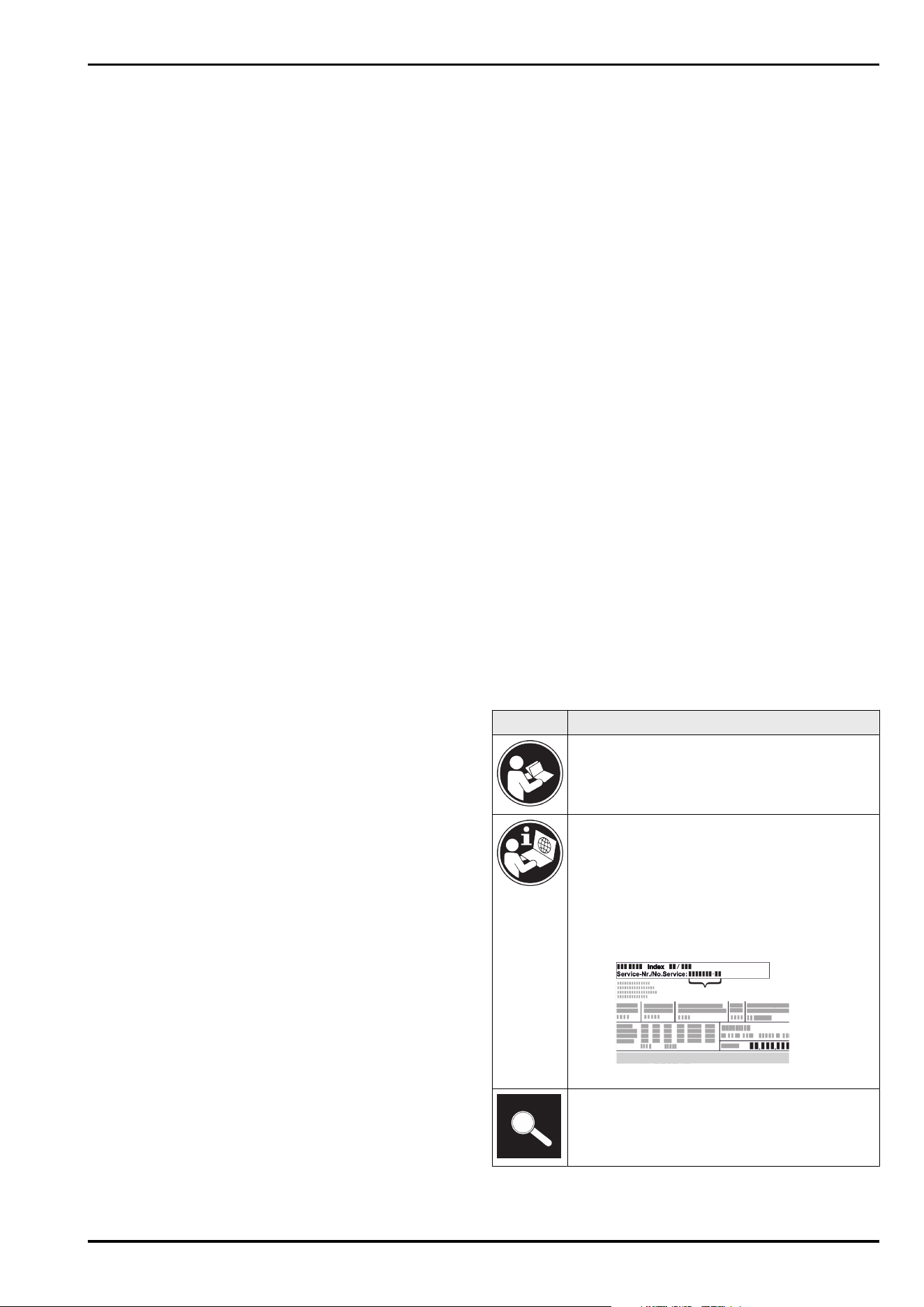
Read instructions
Please read the information in these instruc‐
tions carefully to understand all of the benefits
of your new appliance.
Additional information on the Internet
The digital manual with additional informa‐
tion and in other languages can be found
via the QR code on the front of the
manual or by entering the service number at
home.liebherr.com/fridge-manuals.
The service number can be found on the serial
tag:
Fig.Example illustration
Check appliance
Check all parts for transport damage. If you
have any complaints, please contact your
agent or customer service.
2 * Depending on model and options
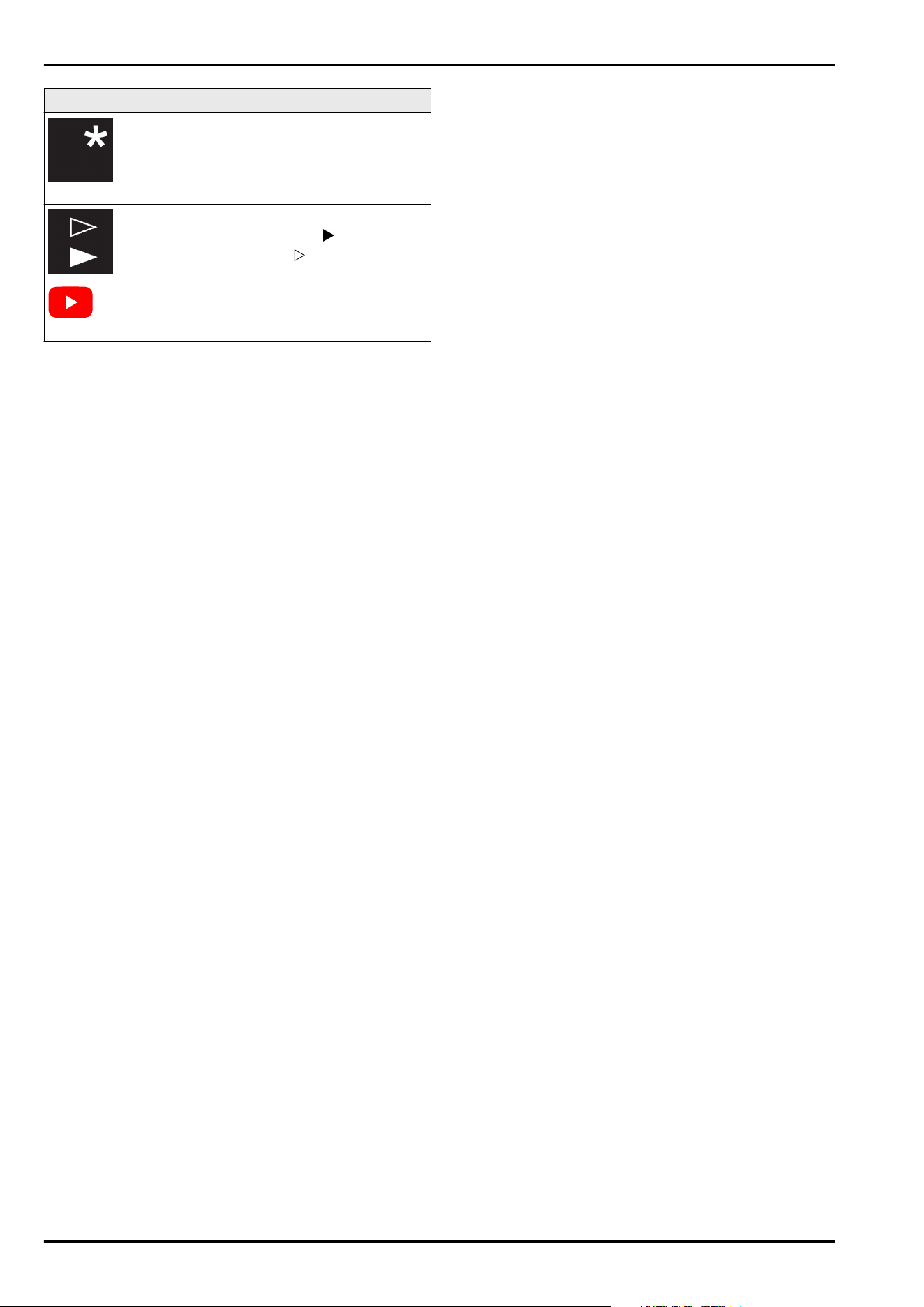
Symbol Explanation
Differences
These instructions apply to a range of models,
so differences are possible. Sections that
apply to certain models only are marked with
an asterisk (*).
Instructions and results
Instructions are marked with a .
Results are marked with a .
Videos
Videos about the appliances are available on
the YouTube channels of Liebherr-Hausgeräte.
Open source licences:
The appliance contains software components that use
open source licences. Information on the open source
licences used can be found here: home.liebherr.com/
open-source-licences
These operating instructions apply to:
-
SRPvh 1402
-
SRPvh 1412
-
SRPvh 6501
-
SRPvh 6511
-
SRPvh 8401
-
SRPvh 8411
1 General safety instructions
Please keep these operating instructions in a safe place so
you can refer back to them at any time.
If you pass the appliance on, please hand these operating
instructions to the next user.
Read these operating instructions carefully before use to
ensure safe and correct use of the appliance. Follow the
instructions, safety instructions and warning messages
included at all times. They are important for ensuring you
can operate and install the appliance safely and without any
problems.
Danger for the user:
-
This appliance may only be used by specialist and labora‐
tory personnel who have been trained for this purpose
and are familiar with all safety measures pertaining
to laboratory work. Children and persons with reduced
physical, sensory or mental capabilities or lack of expe‐
rience and knowledge must not commission or operate
this appliance.
-
The socket must be easily accessible so that the appli‐
ance can be disconnected quickly from the electricity
supply in an emergency. It must not be located in the
area behind the appliance.
-
When disconnecting the appliance from the supply,
always take hold of the plug. Do not pull the cable.
-
In the event of a fault pull out the mains plug or deacti‐
vate the fuse.
-
WARNING: Do not damage the mains power cable. Do
not operate the appliance with a defective mains power
cable.
-
WARNING: Multiple sockets/distributors and other elec‐
tronic equipment (such as halogen transformers) must
not be placed or operated at the rear of the appliance.
-
WARNING: Keep ventilation openings, in the appliance
enclosure or in the built-in structure, clear of obstruction.
-
Only customer service or other specially trained staff
may repair or perform other operations on the appliance.
-
Only assemble, connect and dispose of the appliance
according to the instructions.
Fire hazard
-
The coolant used (information on the model plate) is
ecofriendly but also flammable Any leaking coolant may
ignite.
•
WARNING: Do not damage refrigeration circuit.
•
Do not handle ignition sources inside the appliance.
•
WARNING: Do not use electrical appliances in the
fridge compartment which do not comply with the
design recommended by the manufacturer.
•
If the refrigerant leaks: remove any naked flames or
ignition sources from the vicinity of the leakage point.
Properly air the room. Inform customer services.
-
Do not operate the appliance close to explosive gases.
-
Do not store or use petrol or other flammable gases and
liquids close to the appliance.
-
Do not store any explosive substances, such as aerosol
containers with flammable propellant gas, in the appli‐
ance. To identify these spray cans, look for the list of
contents printed on the can, or a flame symbol. Gases
possibly escaping may ignite due to electrical compo‐
nents.
-
Keep burning candles, lamps and other items with naked
flames away from the appliance so that they do not set
the appliance on fire.
-
Alcoholic liquids or other containers with alcohol inside
must only be stored tightly sealed. Any alcohol that leaks
out may be ignited by electrical components.
Danger of tipping and falling:
-
WARNING: In order to prevent danger due to an unstable
appliance, it must be fixed in accordance with the
instructions.
-
Do not misuse the plinth, drawers, doors etc. as a step or
for support.
Danger of frostbite, numbness and pain:
-
Avoid prolonged skin contact with cold surfaces or refri‐
gerated/frozen goods or take protective measures, e.g.
wear gloves.
Danger of injury and damage:
-
WARNING: Do not use mechanical equipment or other
methods to speed up the defrosting process other than
those recommended by the manufacturer.
-
WARNING: Risk of injury due to electric shock! There are
live electrical parts under the cover.
Only have the LED interior lighting replaced or repaired by
customer service or other suitably trained professionals.
-
NOTICE: Appliance must only be used using original
manufacturer accessories or using accessories from
other providers approved by the manufacturer. The user
bears the risk of using accessories which are not
approved.
Risk of crushing
-
Do not hold the hinge when opening and closing the door.
Fingers may get caught.
Specialist personnel qualifications:
The appliance may only be installed, tested, maintained,
and commissioned by specialist personnel who are
familiar with the installation, commissioning, and opera‐
tion of the appliance.
Specialist personnel are persons who, on account of their
specialist training, knowledge and experience as well as
their knowledge of the relevant standards, are able to
assess and perform the work assigned to them and iden‐
General safety instructions
* Depending on model and options 3
tify potential hazards. They must have training, instruc‐
tion, and authorisation to work on the appliance.
Symbols on the appliance:
This symbol may be located on the
compressor. It relates to the oil in the
compressor and makes reference to the
risk that:Swallowing or inhaling can be
fatal. This advice is only relevant to recy‐
cling. There is no danger in normal opera‐
tion.
WARNING: Danger of fire / flammable
materials. This symbol is located on the
compressor and indicates the danger of
flammable materials. Do not remove the
sticker.
The symbol is located on the back of the
appliance near the alarm relay and indi‐
cates the following danger: Electric shock!
Even if an appliance is disconnected from
the mains there may still be extraneous
voltage. Do not remove sticker.
This or a similar sticker may be located
on the rear of the appliance. This sticker
indicates that there are vacuum insulation
panels (VIP) or perlite panels in the door
and/or housing. This advice is only relevant
to recycling. Do not remove the sticker.
This or a similar sticker may be located on
the rear of the appliance. It refers to the
Li-ion self-charging battery installed. This
advice is only relevant to recycling. Do not
remove sticker.
Please note the warning messages and other specific
advice in the other chapters:
DANGER
Indicates an immediately hazardous
situation which will lead to death or
serious injuries if it is not avoided.
WARNING
Indicates a hazardous situation which
will lead to death or serious injuries if
it is not avoided.
CAUTION
Indicates a hazardous situation which
will lead to minor or moderate injuries
if it is not avoided.
NOTICE
Indicates a hazardous situation which
may lead to damage to property if it is
not avoided.
Note Indicates useful instructions and tips.
2 Appliance at a glance
2.1 Scope of supply
Check all parts for transport damage. If you have any
complaints, please contact your dealer or Customer Service.
(see 10.3 Customer Service)
The delivery comprises the following parts:
-
Free-standing appliance
-
Equipment *
-
Installation materials *
-
Operating instructions
-
Service brochure
-
Quality certificate *
-
Mains cable
-
Remote control
-
Emergency unlocking key
-
Wall fastening kit
-
Sealing plug (to close the drain opening for cleaning
water)
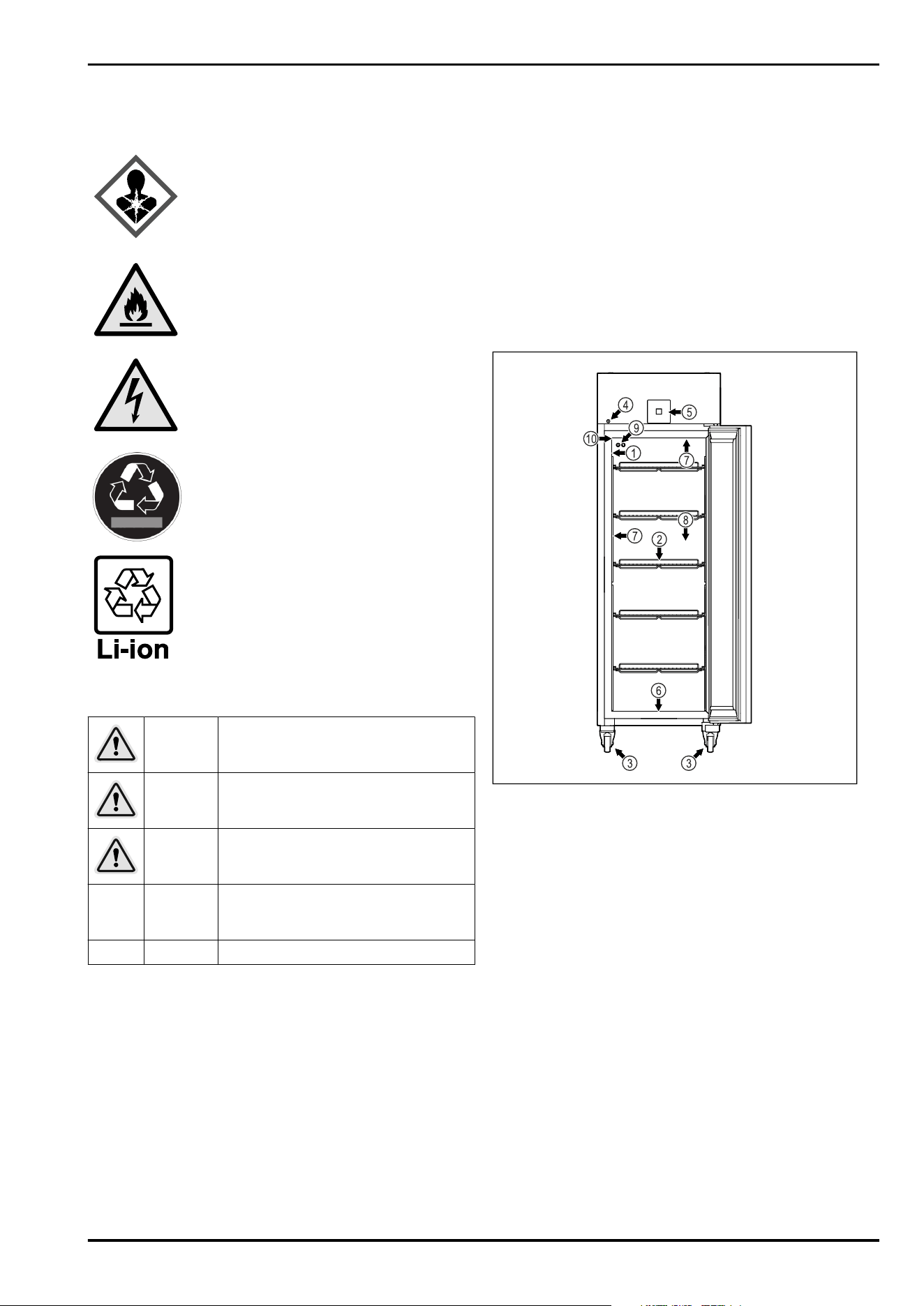
2.2 Overview of appliances and equip‐
ment
SRPvh 6501
SRPvh 8401
Fig. 1 Example illustration
(1)
Type plate (6) Drain hole for water from
cleaning
(2) Grid shelves (7) Interior lighting *
(3) Castors (8) Safety thermostat
sensor
(4) Lock (9) P sensor
(5) Control elements and
temperature display
(10) Sensor feedthrough
SRPvh 6511
SRPvh 8411
Appliance at a glance
4 * Depending on model and options
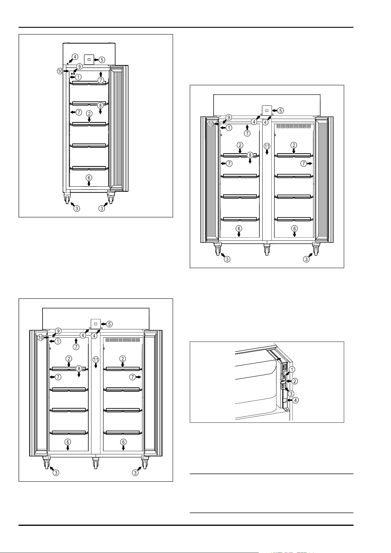
Fig. 2 Example illustration
(1)
Type plate (6) Drain hole for water from
cleaning
(2) Grid shelves (7) Interior lighting *
(3) Castors (8) Safety thermostat
sensor
(4) Lock (9) P sensor
(5) Control elements and
temperature display
(10) Sensor feedthrough
SRPvh 1402
Fig. 3 Example illustration
(1)
Type plate (7) Interior lighting *
(2) Grid shelves (8) Safety thermostat
sensor
(3) Castors (9) P sensor
(4) Lock (10) Sensor feedthrough
(5) Control elements and
temperature display
(11) Centre grid shelf
(6) Drain hole for water
from cleaning
SRPvh 1412
Fig. 4 Example illustration
(1)
Type plate (7) Interior lighting *
(2) Grid shelves (8) Safety thermostat
sensor
(3) Castors (9) P sensor
(4) Lock (10) Sensor feedthrough
(5) Control elements and
temperature display
(11) Centre grid shelf
(6) Drain hole for water
from cleaning
Fig. 5 Example illustration
(4)
Connection for P
sensor
(3) Potential-free alarm
output
(2) USB interface (4) LAN interface
2.3 Special features
Note
You can obtain accessories from customer service
(see 10.3 Customer Service) or from specialised dealers via
the dealer search on our service page on the Internet:
home.liebherr.com
Appliance at a glance
* Depending on model and options 5
SmartModule
The appliance is fitted with a SmartModule.
It is a WLAN and LAN interface for the connection between
the appliance and an external documentation and alarm
system such as Liebherr SmartMonitoring dashboard.
Liebherr SmartMonitoring dashboard is not available
in all countries. Check availability via the QR code
(see 7.2.18WiFi connection ) by entering your model.
Retrofitting drawers
When retrofitting drawer systems in Liebherr refrigera‐
tors/freezers that are used to store temperature-sensitive
materials such as medicines requiring refrigeration and
refrigerated goods that are subject to special standard
requirements, a temperature qualification is required.
Retrofitting drawers in Liebherr refrigerators/freezers can
lead to spoilage of the stored goods or damage to
the stored goods. Therefore, retrofitting must only be
carried out by authorised service providers of the refriger‐
ator/freezer manufacturer.
2.4 Range of use of appliance
Intended use
This laboratory refrigerator is suitable for the professional
storage of products at temperatures between:
-
Foamed door: -2°C and 16°C.*
-
Glass door: 0°C and 16°C.*
Typical products to be stored include research samples,
reagents, laboratory inventory etc.
The appliance meets the requirements of DIN 13277 Refrig‐
erators and freezers for laboratory and medical applications.
The storage of temperature-sensitive substances requires
the use of an independent, continuous monitoring alarm
system. This alarm system must be designed in such a way
that a responsible person can register any alarm status so
that appropriate action can be taken.
Foreseeable incorrect use
Do not use the appliance for the following applications:
-
Storage and refrigeration of:
•
Chemically unstable, flammable or corrosive
substances
•
Blood, plasma or other body fluids for the purpose
of infusion, application or introduction in the human
body.
-
Use in potentially explosive atmospheres.
-
Use outdoors or in areas exposed to dampness and
splashing water.
-
Use in residential areas because adequate protection of
radio reception cannot be ensured in such environments.*
Improper use of the appliances will result in goods stored
being damaged or spoiled.
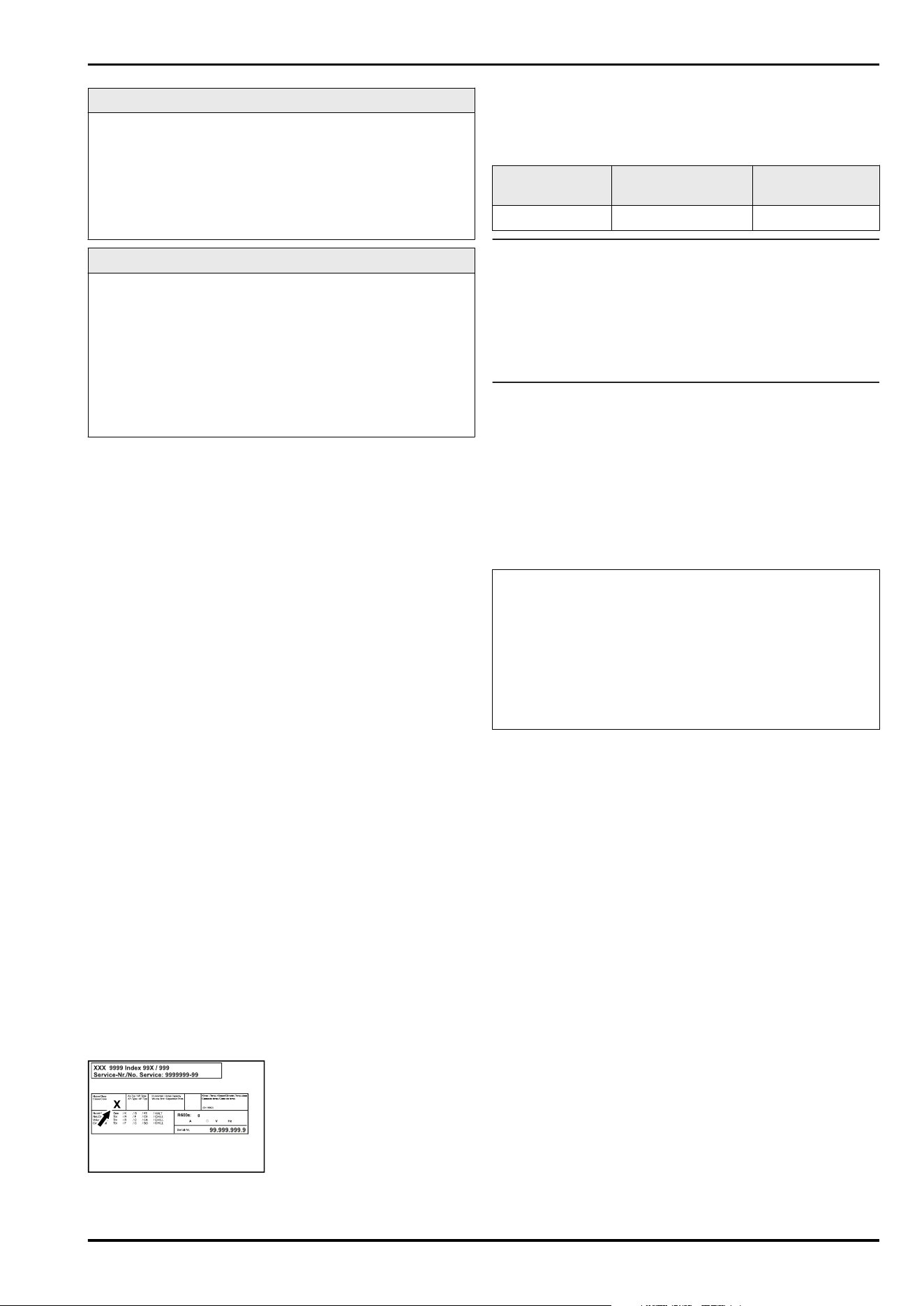
Climate classes
The applicable climate class for your appliance is printed on
the type plate.
Fig. 6 Type plate
(X)
This climate class indi‐
cates the ambient
conditions in which
the appliance can be
safely operated.
Climate class (X) max. room tempera‐
ture
max. rel. humidity
7 35°C 75%
Note
The minimum permitted room temperature at the setup
location is 10°C.
The internal temperature of the appliance never exceeds the
ambient temperature at the site of use.
Under borderline conditions, slight condensation may form
on the glass door (depending on the equipment) and on the
side walls.
2.5 Appliance noise emissions
The A-weighted emission sound pressure level during oper‐
ation of the appliance is under 70 dB(A) (sound power rel.
1 pW).
2.6 Conformity
The coolant circuit has been tested for leak-tightness. The
appliance complies with the relevant safety regulations.
The designated product complies with the provisions of
the following European directives and regulations:
(EU) 2019/2020, 2014/35/EU, 2014/30/EU, 2011/65/EU
The built-in radio module complies with Direc‐
tive 2014/53/EU. Information on the radio module
(see 10.1 Technical specifications) .
The full text of the EU Declaration of Conformity is avail‐
able at the following web address: www.liebherr.de
2.7 SVHC substances according to
REACH regulation
You can check whether your appliance contains SVHC
substances according to REACH regulation at the following
link: home.liebherr.com/de/deu/de/liebherr-erleben/nach‐
haltigkeit/umwelt/scip/scip.html
3 Setting up and connecting
3.1 Installation requirements
The installation conditions are crucial to ensure that you
can operate your appliance safely, efficiently and without
problems.
-
Observe all safety instructions.
-
Consider the location and position in the room.
Setting up and connecting
6 * Depending on model and options
WARNING
Danger of fire due to incorrect positioning!
If the mains cable or plug touches the back of the appli‐
ance, the vibration can damage the mains cable or the plug
resulting in a short circuit.
► Make sure the mains cable is not trapped under the appli‐
ance when you position the appliance.
► Stand the appliance so that it is not touched by connec‐
tors or main cables.
► Do not connect any appliances to sockets in the area of
the back of the appliance.
► Do not place and operate multi-sockets/power distribu‐
tors and other electronic devices (such as halogen trans‐
formers) at the back of the appliances.
WARNING
Fire hazard due to dampness!
If live parts or the mains lead become damp this may cause
short circuits.
► The appliance is designed for use in enclosed areas. Do
not operate the appliance outdoors or in areas where it is
exposed to splash water or damp conditions.
WARNING
Leaking coolant and oil!
Fire. The coolant contained in the appliance is eco-friendly,
but also flammable. The oil contained in the appliance
is flammable. Escaping coolant and oil can ignite if the
concentration is high enough and in contact with an
external heat source.
► Do not damage the pipelines of the coolant circuit and
the compressor.
3.1.1 Installation site
-
A dry and well-ventilated room is an optimum installation
location.
-
If the appliance is installed in a very damp environment,
condensation may form on the appliance exterior.
Always make sure there is good ventilation and aeration
at the installation site.
-
The more refrigerant there is in the appliance, the larger
than room must be in which it is located. In rooms that
are too small, a leak can product a flammable gas/air
mixture. For every 8g of refrigerant, the installation room
must be at least 1 m
3
in size. Information on the refrig‐
erant contained is given on the type plate inside the
appliance.
-
The floor on which the appliance stands must be hori‐
zontal and level.
-
The site of use must be able to bear the weight of the
device including the maximum load. (see 10.1 Technical
specifications)
3.1.2 Position in space
-
Do not place the appliance in direct sunlight or near radi‐
ators or similar sources of heat.
-
Always position the appliance with the rear directly on
the wall.
-
Use in hazardous areas is not permitted.
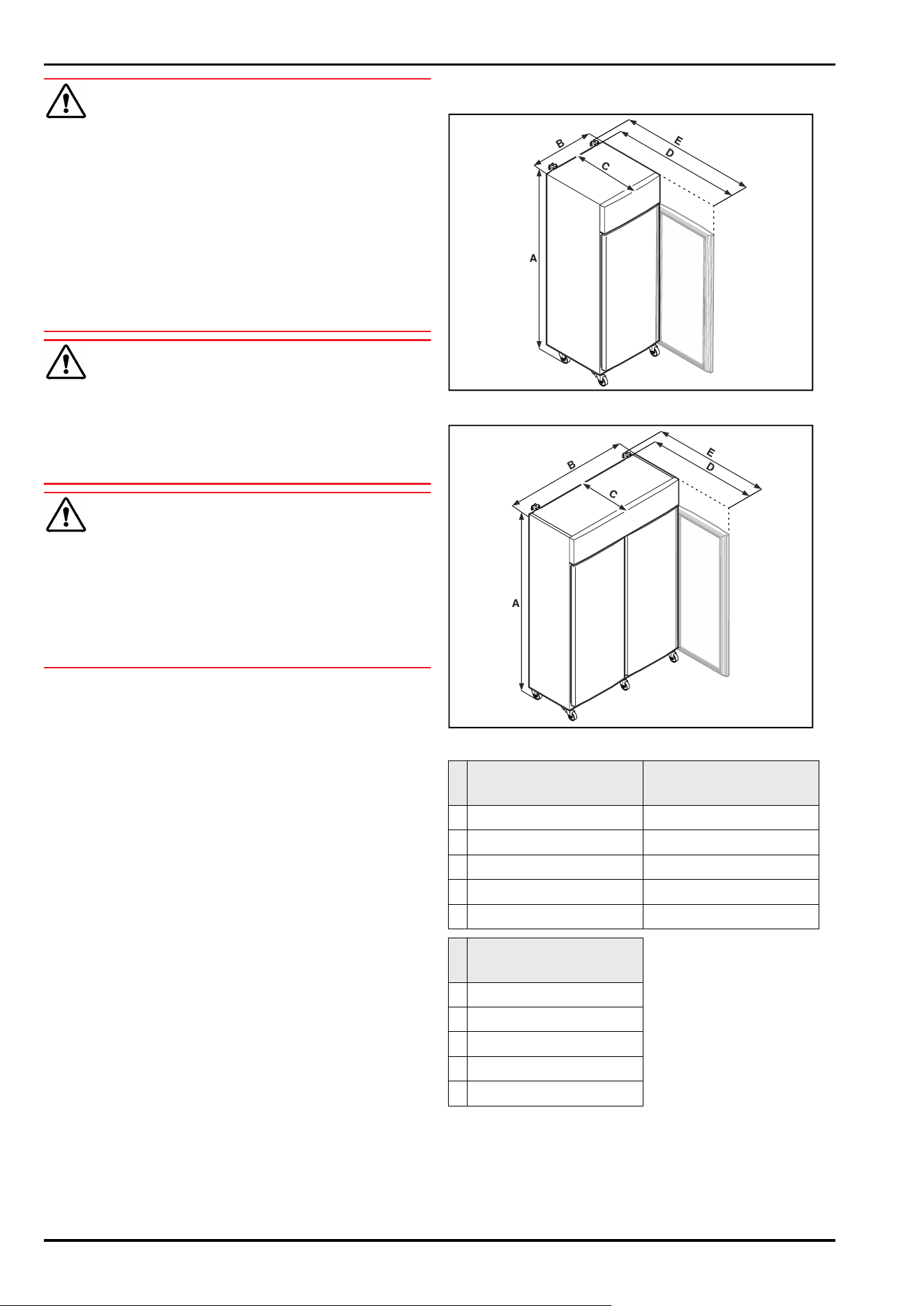
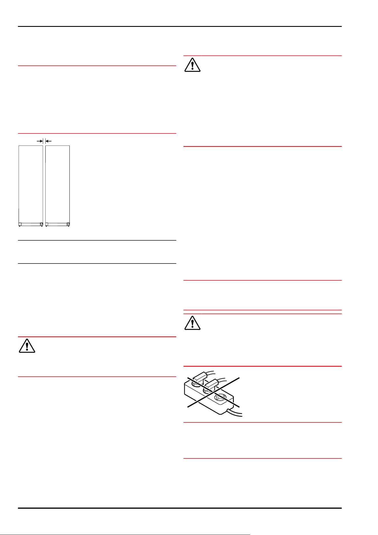
3.2 Appliance dimensions
Fig. 7 Example illustration
Fig. 8 Example illustration
SRPvh 1402
SRPvh 1412
SRPvh 6501
SRPvh 6511
A 2135mm 2135mm
B 1427mm 697mm
C 867mm 867mm
D 1500mm 1500mm
E 1532mm 1532mm
SRPvh 8401
SRPvh 8411
A 2135mm
B 787mm
C 1017mm
D 1740mm
E 1772mm
A = appliance height including feet (minimum) / castors
B=appliance width without handle
C = appliance depth without handle
D = appliance depth with door open
F = appliance depth with protruding handle and anti-tipping
device
Setting up and connecting
* Depending on model and options 7
3.3 Transporting the appliance
WARNING
Risk of injury due to broken glass!*
When transporting at an altitude of more than 1500 m, the
glass panes of the door may break. This can result in sharp-
edged fragments, which can cause serious injuries.
► Take appropriate protective action.
DANGER
Risk of injury and damage due to heavy appliance!
► Always transport the appliance with at least two people.
DANGER
Risk of injury and damage due to the appliance tipping over!
► Pay attention to uneven floors and ramps when trans‐
porting appliances.
3.3.1 Transporting the appliance for initial use
Ensure that the following requirements are met:
❑
The appliance is upright.
❑
If necessary: The two-door appliance is dismantled for
transport.
► Transport the appliance with at least two people.
3.3.2 Transporting the appliance after initial
use
Observe the following instructions if you wish to transport
or move the appliance again after initial use.
Ensure that the following requirements are met:
❑
The appliance is emptied.
❑
The appliance is upright.
❑
Appliance with door(s): Door is secured against acci‐
dental opening.
❑
Appliance with telescopic unit: The telescopic unit is
secured against accidental opening.
❑
Appliance with adjustable feet: Adjustable feet are
screwed in.
► If necessary: Dismantle and transport the appliance as
for initial commissioning. (see 3.3.1 Transporting the
appliance for initial use)
After transport:
► Align the appliance.
3.4 Unpacking appliance
► Check the appliance and the packaging for damage
during transport. Contact the supplier immediately if you
suspect any damage. Do not connect appliance to the
power supply.
► Remove all packaging materials from the rear or the side
walls of the fridge that may prevent proper installation or
prevent air flow and ventilation.
3.5 Reversing the door opening direc‐
tion
3.5.1 Safety notes
WARNING
Risk of injury if the door is not reversed correctly!
► Replace the door hinge with specialist personnel.
WARNING
Risk of injury and material damage due to heavy door!
► Only perform the conversion if you can carry a weight of
45 kg.
► Always have someone help you carry out the conversion.
NOTICE
Live parts!
Damage to electrical components.
► Remove the mains plug before you reverse the door.
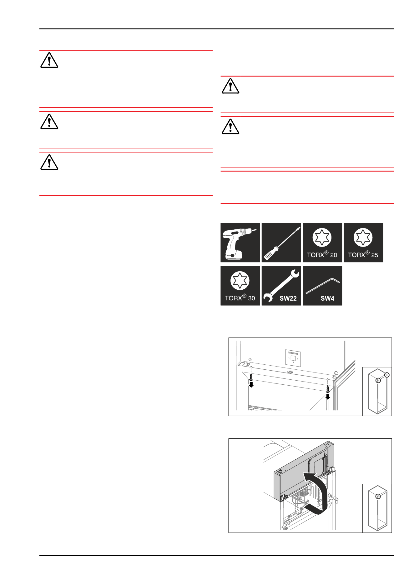
3.5.2 Tools
3.5.3 Opening the aggregate cover
► Open the door.
Fig.9
► Remove the screws.
Fig. 10
Setting up and connecting
8 * Depending on model and options
► Lift the aggregate cover.
► Hold on to the cover.
-or-
Fig.11
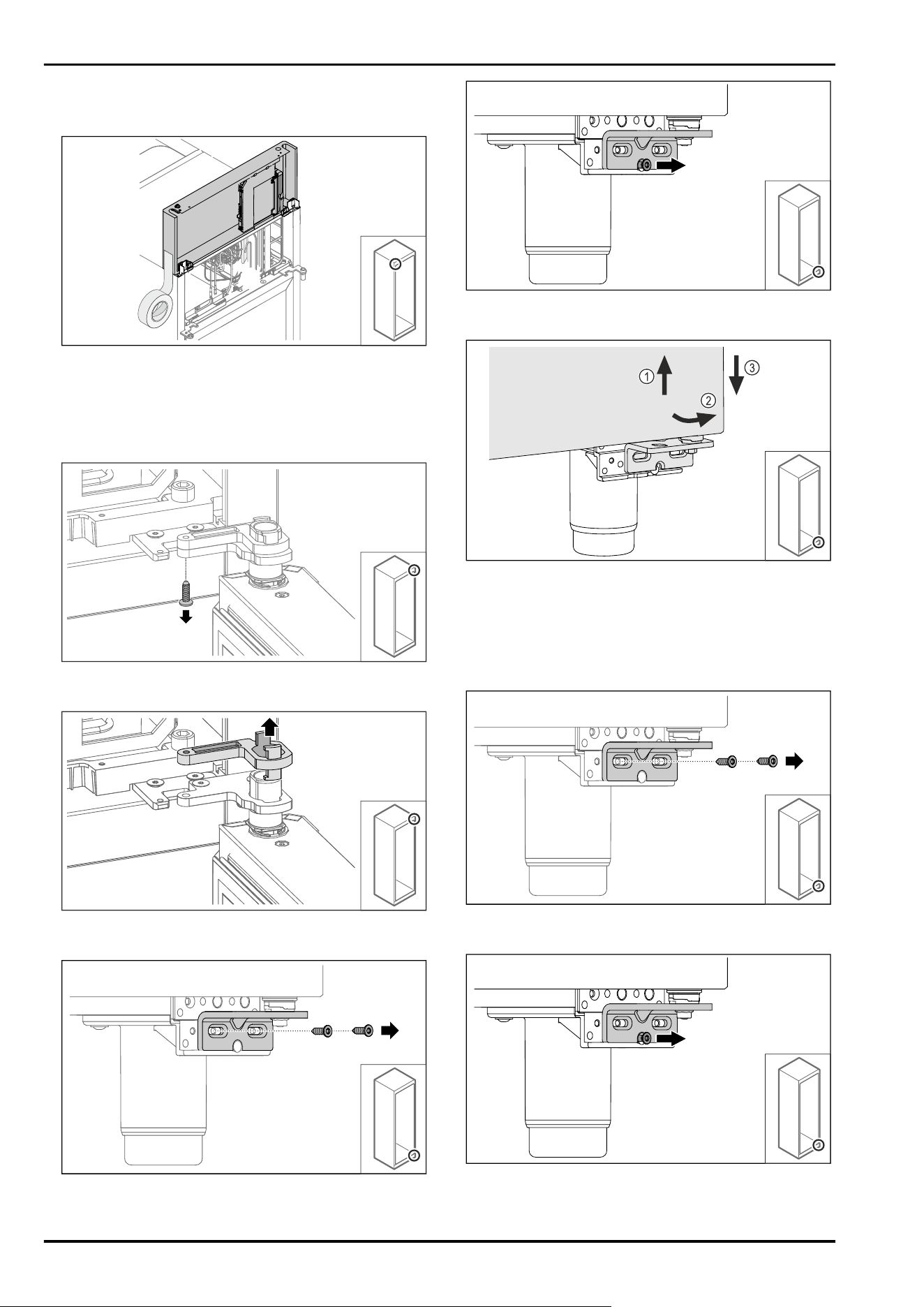
► Fix the cover.
3.5.4 Removing the door
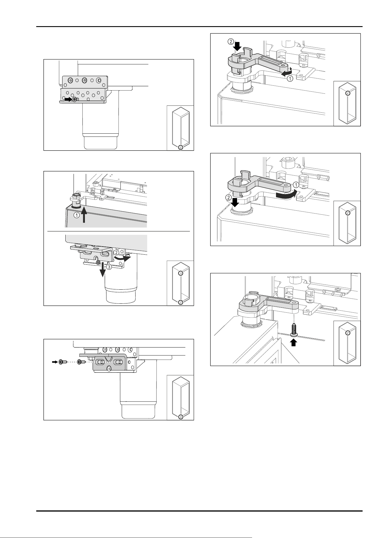
3.5.4 Removing the door (glass door)*
Fig.12
► Remove the screw.
Fig.13
► Remove the swap bearing block lock.
Fig. 14
► Remove the screws.
Fig. 15
► Loosen screw.
Fig. 16
► Lift the door slightly Fig. 16 (1), tilt it forwards at the
bottom Fig. 16(2) and lower it Fig. 16(3).
► Place the door on a soft surface.
▷ Glass door is removed.
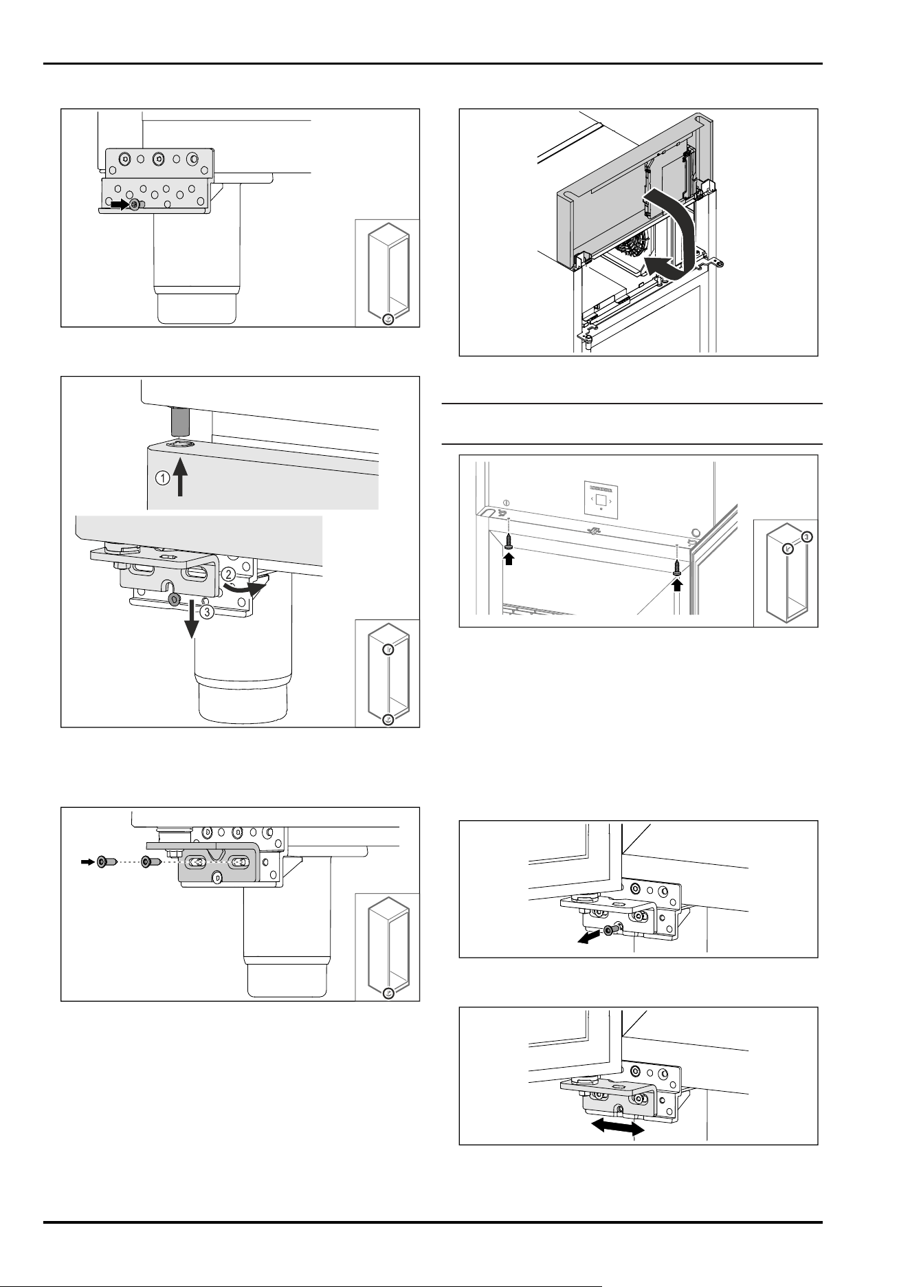
3.5.4 Removing the door (foamed door)*
Fig.17
► Remove the screws.
Fig. 18
► Loosen screw.
Setting up and connecting
* Depending on model and options 9
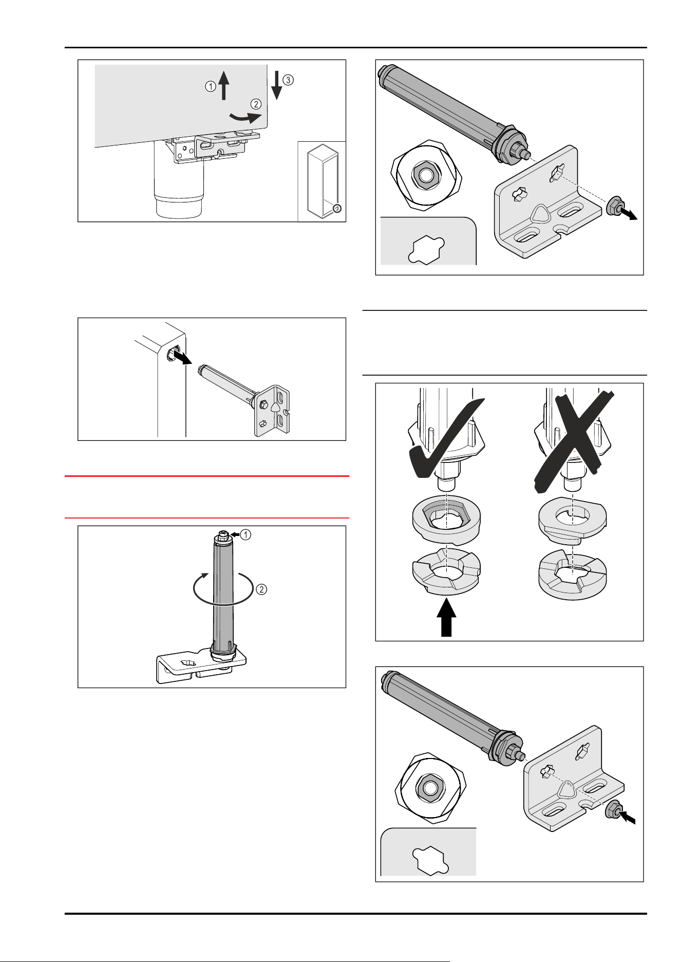
Fig. 19
► Lift the door slightly Fig. 19 (1), tilt it forwards at the
bottom Fig. 19(2) and lower it Fig. 19(3).
► Place the door on a soft surface.
▷ Foamed door is removed.
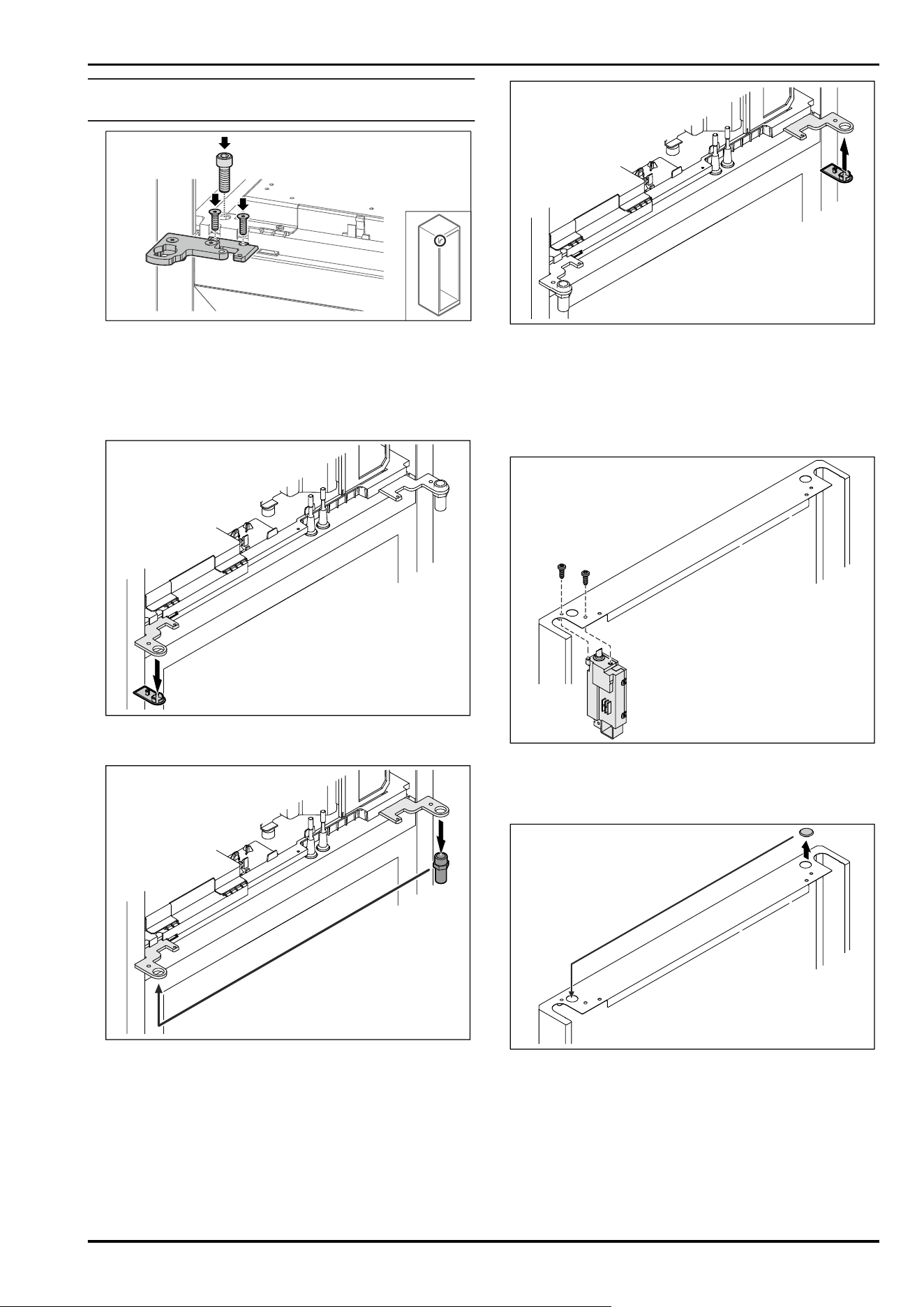
3.5.5 Converting the lower locking system
Fig.20
► Pull the lower hinge bracket out of the door.
NOTICE
Danger of injury due to tensioned spring!
► Do not disassemble the door locking system Fig.21(1).
Fig.21
► Turn the locking system Fig.21(2) until it clicks.
▷ Preload of the locking system is released.
Fig. 22 Right-hinged
► Loosen nut.
Note
Incorrect alignment of the height adjustment washers.
Nuts no longer have sufficient hold.
► The washer must lock into the underside of the closing
system.
Fig.23
Fig. 24 Left-hinged
Setting up and connecting
10 * Depending on model and options
► Change over the closing system and tighten; observe the
alignment of the closing system.
▷ Lower locking system has been converted.
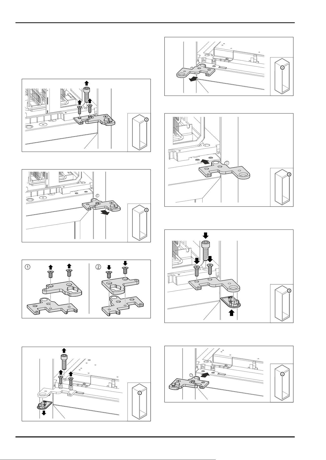
3.5.6 Converting the upper locking system
3.5.6 Converting the upper locking system
(glass door)*
Fig.25
► Remove the screws.
Fig. 26
► Remove the two-part hinge bracket.
Fig.27
► Disassemble the two-part hinge bracket. Fig.27(1)
► Reassemble the two-part hinge bracket rotated by 180°.
Fig.27(2)
Fig.28
►
Remove the screws and cover.
Fig.29
► Remove the hinge bracket.
Fig.30
► Re-locate the hinge angle by turning 180° to the opposite
side.
Fig.31
► Tighten the hinge bracket.
► Put on the cover.
Fig.32
► Re-locate the two-part hinge bracket to the opposite
side.
Setting up and connecting
* Depending on model and options 11
Note
Do not pinch the cable.
Fig.33
► Tighten the two-part hinge bracket.
▷ Upper locking system has been converted.
3.5.6 Converting the upper locking system
(foamed door)*
Fig.34
► Remove cover.
Fig.35
► Re-locate the bolt in the hinge bracket.
► Tighten the bolt to a torque of 12 Nm.
Fig.36
► Put on the cover.
▷ Upper locking system has been converted.
3.5.7 Changing over the lock
3.5.7 Re-locating the lock (electronic lock)
Fig.37
► Remove the screws and remove the lock.
► The connected cable remains in the lock. Loosen any
fasteners.
Fig.38
► Swap the cover to the opposite side.
Setting up and connecting
12 * Depending on model and options
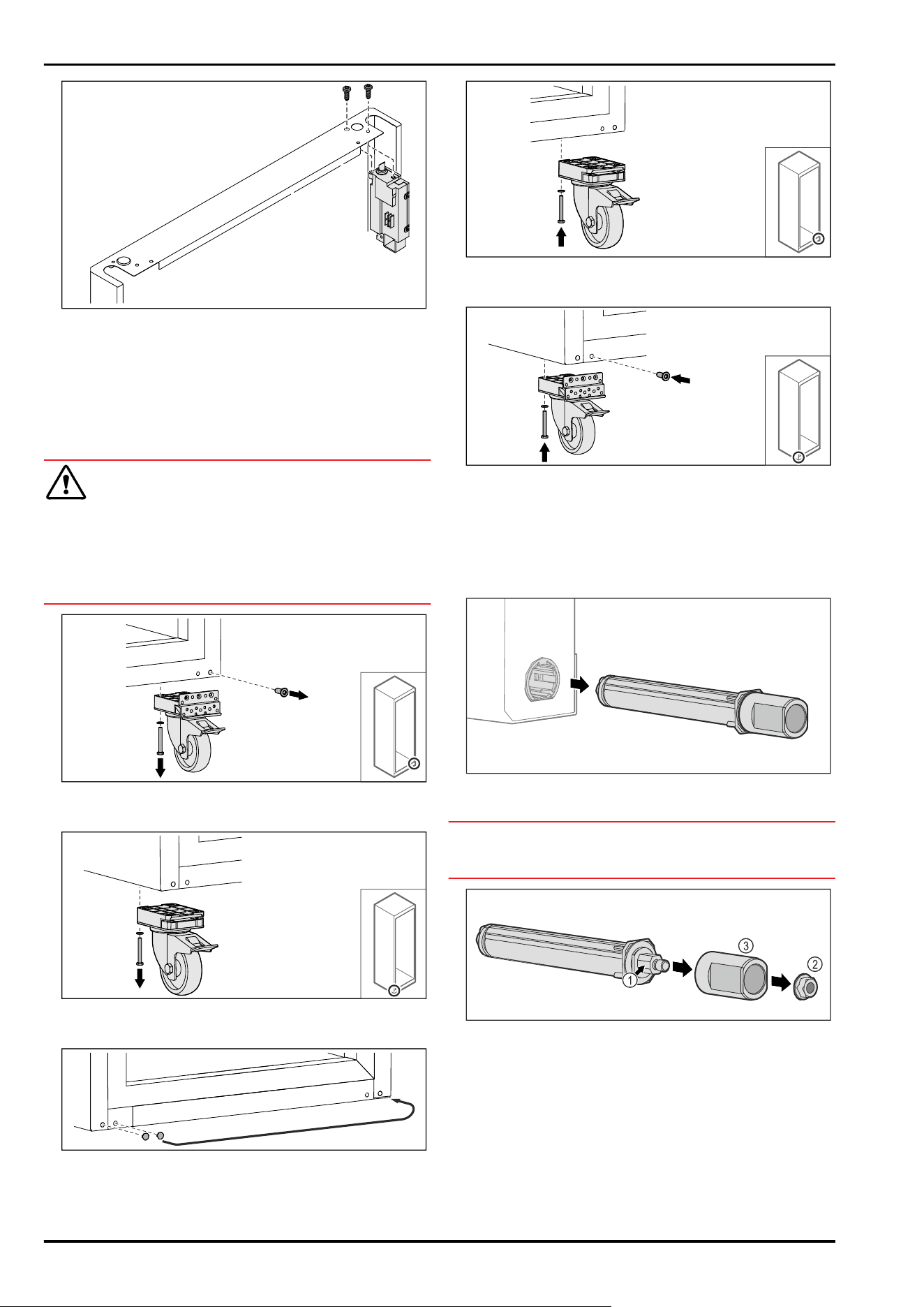
Fig. 39
► Insert the lock and screw in place.
▷ The electronic lock has been implemented.
3.5.8 Re-locating the swap bearing block
3.5.8 Re-locating the swap bearing block
(casters)
WARNING
Danger of injury and damage due to appliance tipping over!
Danger to life and material damage to appliance. If you
remove the casters from the appliance, the appliance can
tip over.
► Before performing a conversion on the appliance: Secure
appliance against tipping over.
Fig.40
► Unscrew and remove casters.
Fig. 41
► Unscrew and remove casters with bearing bracket.
Fig. 42
► Swap over covers.
Fig.43
► Screw on casters.
Fig.44
► Screw on casters with bearing bracket.
▷ Swap bearing block is relocated.
3.5.9 Converting the door
3.5.9 Converting the door (glass door)*
Fig.45
► Pull the upper locking system out of the door.
NOTICE
Danger of injury due to tensioned spring!
► Do not disassemble the door locking system Fig.46(1).
Fig.46
► Remove the Fig.46(2) nuts.
► Take off the Fig.46(3) sleeve.
Setting up and connecting
* Depending on model and options 13
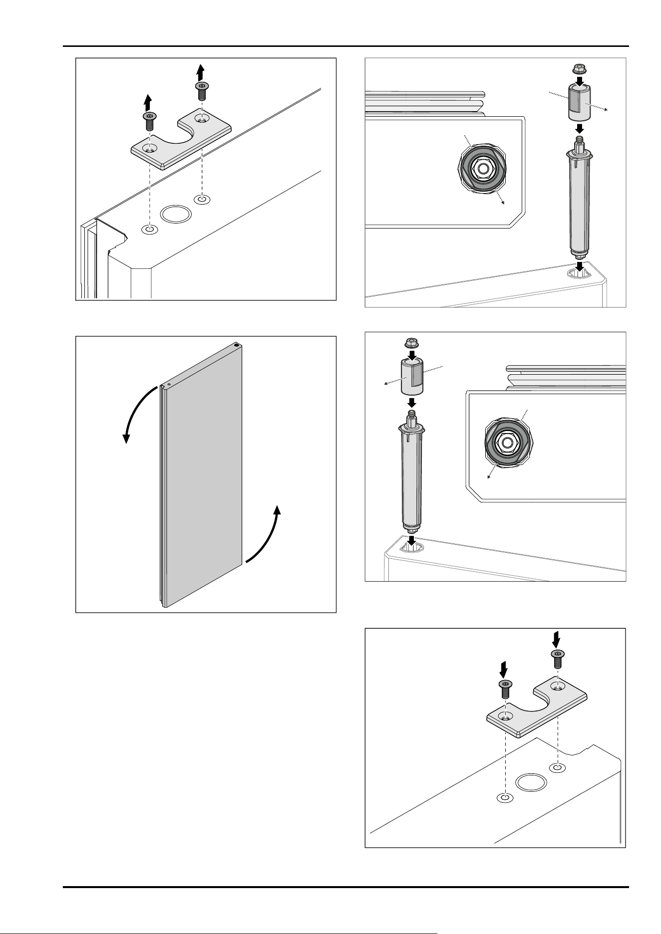
Fig. 47
► Unscrew the cover.
Fig. 48 Example illustration
► Turn the door 180°.
Fig. 49 Right stop
Fig. 50 Left stop
► Fit the upper locking system and insert on the hinge side,
paying attention to the alignment of the sleeve.
Fig.51
► Screw on the cover.
Setting up and connecting
14 * Depending on model and options
▷ Glass door is converted.
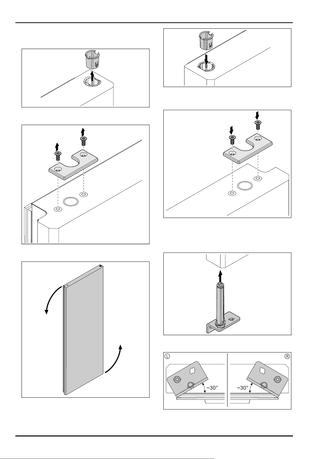
3.5.9 Converting the door (foamed door)*
Fig.52
► Pull out the hinge bushing on the opposite side.
Fig.53
► Unscrew the cover.
Fig.54
► Turn the door 180°.
Fig.55
► Insert the hinge bushing at the top of the hinge side (the
flattened side faces outwards).
Fig.56
► Screw on the cover.
▷ Foamed door is converted.
3.5.10 Fitting the lower locking system
Fig.57
► Slide the closing system into the door.
Fig. 58 Door from below
▷ Alignment of closing system installation for left-hinged
(L) or right- hinged (R).
Setting up and connecting
* Depending on model and options 15
3.5.11 Fitting the door
3.5.11 Fitting the door (glass door)*
Fig. 59
► Slightly tighten the screw.
Fig.60
► Insert the door slightly tilted at the top Fig. 60 (1), align
the door straight Fig. 60 (2) and place it on the bottom of
the swap bearing block screw Fig.60(3).
Fig.61
► Screw on the door.
Fig. 62
► Turn the swap bearing block lock slightly and Fig. 62 (1)
place it on the sleeve Fig. 62(2).
Fig.63
► Turn the swap bearing block lock back slightly Fig. 63 (1),
press it down Fig.63(2) and lock it at the hinge bracket.
Fig.64
► Open the door.
► Screw on the swap bearing block lock.
▷ Glass door is fitted.
Setting up and connecting
16 * Depending on model and options
3.5.11 Fitting the door (foamed door)*
Fig.65
► Slightly tighten the screw.
Fig.66
► Insert the door slightly tilted at the top Fig. 66 (1), align
the door straight Fig. 66 (2) and place it on the bottom of
the swap bearing block screw Fig.66(3).
Fig. 67
► Screw on the door.
▷ Foamed door is fitted.
3.5.12 Closing the aggregate cover
Fig.68
► Close the aggregate cover.
Note
Do not pinch the cable.
Fig. 69
► Screw on the aggregate cover.
► Close the door.
▷ The door hinge has been changed.
3.6 Aligning the door
3.6.1 Aligning the door horizontally
If the door is not straight, you can adjust it on the lower
hinge.
Fig.70
► Remove the middle screw on the lower hinge.
Fig.71
► Slightly undo both screws and move the door with the
hinge to the left or right.
Setting up and connecting
* Depending on model and options 17
► Fully tighten the screws (the middle screw is no longer
needed).
▷ The door is now straight.
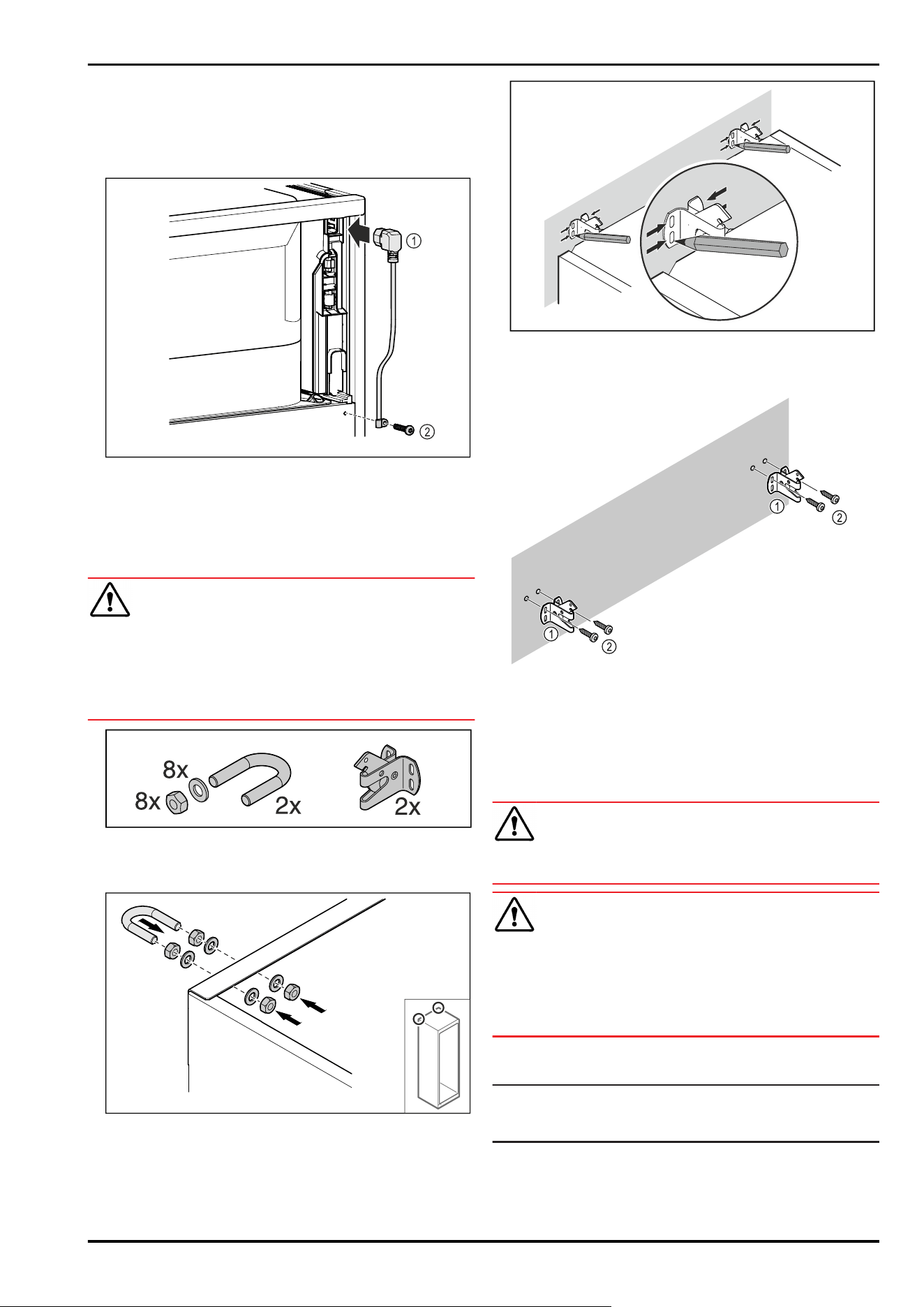
3.7 Connect power cable
Fig.72
► IEC socket of the power cable Fig. 72 (1) on the rear side
of the appliance.
► Install mains tension relief. Fig.72(2)
3.8 Mounting the anti-tipping device
WARNING
Danger of injury and damage due to appliance tipping over!
Danger to life and material damage to the appliance. An
appliance without an anti-tip device fitted can tip over if you
open the door or pull out shelves, for example.
► Before putting the appliance into operation: Always fit
the anti-tilt device according to the instructions.
Fig.73
The anti-tipping device is included with the appliance. It
consists of a retaining part, bracket, 8 washers and 8 nuts.
Fig. 74
► Mount the bracket with included washers and nuts on the
appliance.
► Push appliance with fitted retaining parts against the
wall.
► Level out the appliance.
Fig.75
► Make markings on the wall.
► Remove appliance.
Fig. 76
Use fixing material (e.g. wall anchors) which is appro‐
priate for the nature of the wall or floor (wood,
concrete) and sufficient attachment points.
► Attach retaining hooks.
3.9 Installing appliance
CAUTION
Risk of injury and damage.
► Use 2 people to install appliance.
CAUTION
Risk of injury and damage.
The door can knock against the wall and become damaged
as a result. In the case of glass doors, the damaged glass
can cause injuries.
► Protect the door from knocking against the wall. Attach
door stopper, e.g. felt stopper, to the wall.
► Connect all necessary components (e.g. mains cable) to
the back of the appliance and route to the side.
Note
Cables can be damaged.
► Do not jam the cable when pushing the appliance back.
► Slide appliance up against the wall so that the retaining
parts latch into the securing hooks.
▷ The appliance is now secured against tipping.
▷ It can be released by folding back the securing hooks.
Setting up and connecting
18 * Depending on model and options
► The spacing between the top edge of the device and the
room ceiling must be at least 300mm.
3.10 Installing multiple appliances
NOTICE
Risk of damage due to condensation between the side
walls.
► Do not install the appliance directly next to another
fridge.
► Install appliances with a space 3cm between appliances.
► Only install multiple appliances up to temperatures of
35°C and 65% humidity next to one another.
► At higher levels of humidity, increase space between
appliances.
Fig. 77 Side-by-side installation
Note
A side-by-side kit is available as an accessory via Liebherr
Customer Service. (see 10.3 Customer Service)
3.11 After installation
► Peel off the protective films. *
► Clean appliance. (see 9.3Cleaning the appliance)
► If necessary: Disinfect the appliance.
► Keep the invoice so you have the appliance and dealer
information available if needed.
3.12 Disposing of packaging
WARNING
Danger of suffocation due to packing material and plastic
film!
► Do not allow children to play with packing material.
The packaging is made of recyclable materials:
-
corrugated board/cardboard
-
expanded polystyrene parts
-
polythene bags and sheets
-
polypropylene straps
-
nailed wooden frame with polyethylene panel*
► Take the packaging material to an official collecting
point.
3.13 Connecting the appliance to the
power supply
WARNING
Danger of electric shock and injury due to damaged appli‐
ance or damaged mains cable!
Danger of cuts and fatal injuries. If the appliance or the
mains cable is damaged during transport, you may be elec‐
trocuted. You could also cut yourself on damaged parts of
the appliance housing.
► Check the appliance and the mains cable for damage
after transport.
► Never put the appliance into operation if the appliance or
the mains cable are damaged.
► Contact Customer Service.
You can connect your appliance to the mains using the
power cable supplied separately. The mains power cable
has an appliance coupler at one end and a mains plug at the
other end.
Make sure that the following requirements are fulfilled:
-
The appliance and power cable are undamaged.
-
The appliance is set up in accordance with the regula‐
tions. (see 3.7Connect power cable)
-
Requirements for the electrical connection are met.
(see 3.1 Installation requirements)
-
Dimensions for connection in accordance with regula‐
tions are known and observed.
-
Mains voltage and frequency correspond to the specifica‐
tions on the type plate.
-
The socket is earthed according to the regulations and
fused.
-
The fuse tripping current is between 10A and 16A.
-
The socket is easily accessible and is not behind the
appliance.
NOTICE
Danger of damage to incorrect operation!
Damage to the electrical components of the appliance.
► Only use the supplied mains cable.
WARNING
Danger of fire due to incorrect connection!
Burns.
Damage to the appliance.
► Do not use an extension cable.
► Do not use distributor blocks.
NOTICE
Danger of damage to incorrect connection!
Damage to the appliance.
► Do not connect the appliance to a stand-alone inverter,
e.g. solar power systems and petrol generators.
► Connect the mains cable plug to the power supply.
Ensure that the plug is tightly in the socket.
▷ The standby symbol appears in the display.
▷ If no action occurs within 60 seconds: The standby
symbol fades or disappears.
Setting up and connecting
* Depending on model and options 19
▷ The appliance is connected. For information regarding
first use, see the following section or the operating
instructions.
4 Functionality of the
Touch&Swipe display
You operate your appliance using the Touch & Swipe display.
You select appliance functions in the Touch & Swipe display
(hereafter referred to as display) by tapping them. If you
do not perform any action on the display for 10 seconds,
the display either jumps back to the higher-level menu or
directly to the status display.
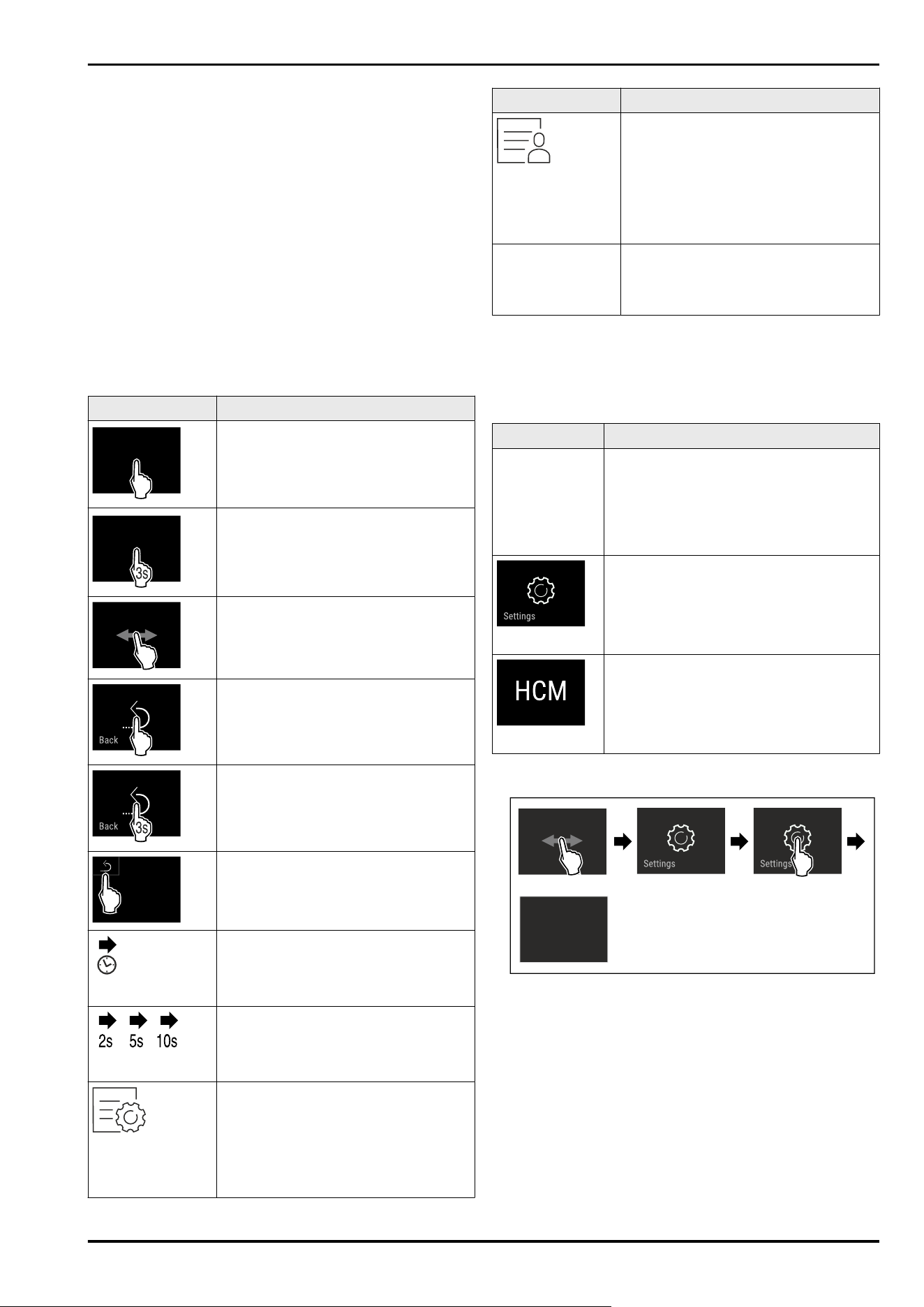
4.1 Navigation and symbol explanation
In the illustrations, different symbols are used to navigate
the display. The following table describes these symbols.
Symbol
Description
Briefly touch the display:
Activates/deactivates function.
Confirms selection.
Opens submenu.
Touch the display for a specified time
(e.g. 3seconds):
Activates/deactivates function or
value.
Swipe left or right:
Navigate in the menu.
Briefly touch the Back symbol:
Jumps back one menu level.
Press and hold the Back symbol for
3seconds:
Jumps back to the status display.
Briefly touch the Back symbol at the
top left:
Jumps back one menu level.
Arrow with clock:
It takes more than 10 seconds for the
following message to appear in the
display.
Arrow with a time indication:
It takes the specified amount of time
until the following message appears in
the display.
“Open Settings menu” symbol:
Navigates to the Settings menu and
opens the settings menu.
If necessary: Navigate to the desired
function in the Settings menu.
(see4.2.1 Opening the Settings menu)
Symbol Description
“Open Advanced menu” symbol:
Navigates to the Advanced menu and
opens the advanced menu.
If necessary: Navigate to the desired
function in the Advanced menu.
(see 4.2.2 Opening the expanded
menu)
No action for
10seconds
If you do not perform any action on
the display for 10 seconds, the display
either jumps back to the higher-level
menu or directly to the status display.
Note: Illustrations of the display are shown in the English
version.
4.2 Menus
The appliance functions are distributed over various menus:
Menu
Description
Main menu When you switch the appliance on, you
are automatically in the main menu.
From here you can navigate to the most
important appliance functions, to the
Settings menu and to the Advanced
menu.
Settings menu
The Settings menu contains additional
appliance functions for setting up your
appliance.
Advanced menu
The advanced menu contains special
appliance functions for setting up your
appliance. Access to the Advanced menu
is protected by the numerical code 151.
4.2.1 Opening the Settings menu
Fig. 78 Example illustration
► Carry out action steps according to the illustration.
▷ Settings menu is open.
► If necessary: Navigate to the desired function.
Functionality of the Touch&Swipe display
20 * Depending on model and options
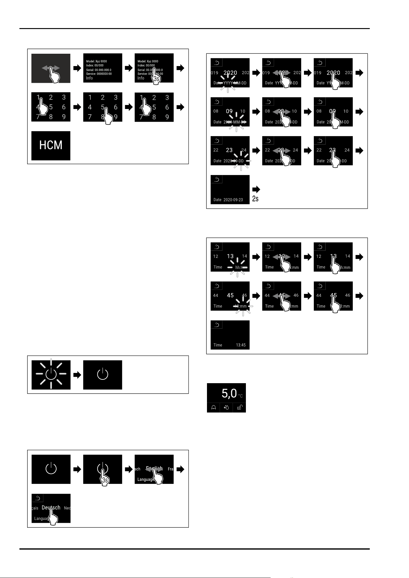
4.2.2 Opening the expanded menu
Fig.79Access with numerical code 151
► Carry out action steps according to the illustration.
▷ The expanded menu is open.
► If necessary: Navigate to the desired function.
4.3 Sleep mode
If you do not touch the display for 1 minute, the display
switches to sleep mode. In sleep mode, the display bright‐
ness is dimmed.
4.3.1 Ending sleep mode
► Touch the display briefly with your finger.
▷ Sleep mode is ended.
5 Putting into operation
5.1 Switching on appliance (first use)
Ensure that the following requirements are met:
- Appliance is installed and connected.
- All adhesive strips, adhesive and protective films and
transport locks are removed from inside and outside the
appliance.
Fig. 80 Example illustration
► The standby symbol is flashing: Wait until the start
process is complete.
▷ The display shows the standby symbol.
If the appliance has been supplied with factory settings,
the screen language and the date/time first need to be set
when using the appliance for the first time.
Fig.81
►
Carry out action steps according to the illustration.
▷ Language is set.
Fig.82
► Carry out action steps according to the illustration.
▷ Date is set.
Fig.83
► Carry out action steps according to the illustration.
▷ Time is set.
Fig. 84 Status display
▷ The appliance is ready for operation once the tempera‐
ture appears in the display.
▷ The temperature display flashes until the set tempera‐
ture is reached.
Putting into operation
* Depending on model and options 21
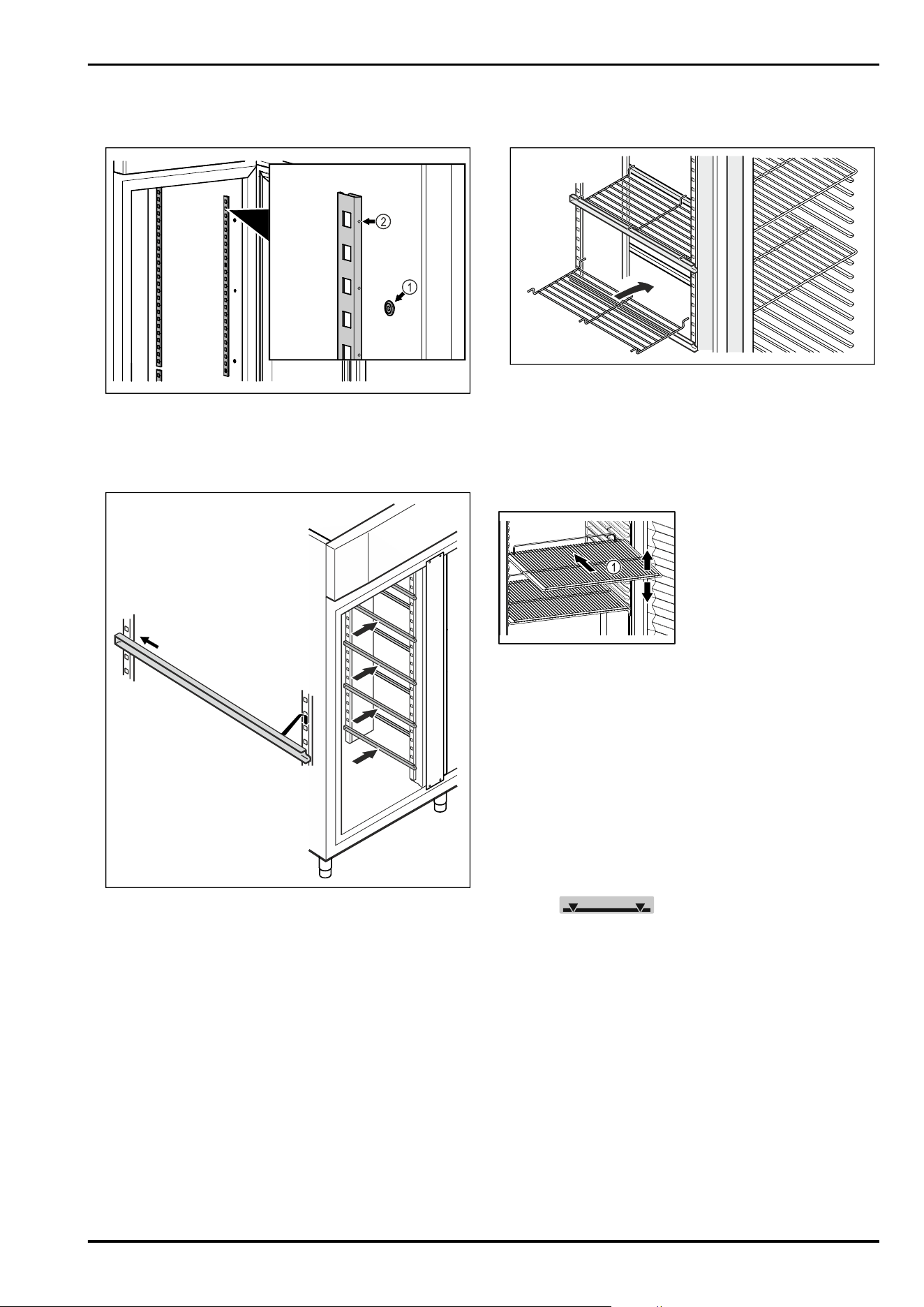
5.2 Using equipment
5.2.1 Inserting the snap strips
Fig. 85 Example illustration
► Hook the snap strips into the suspension Fig. 85 (1). Mark
Fig.85(2) must point forwards.
5.2.2 Inserting support rail
Fig. 86 Example illustration
► Insert support rail into rear snap-in bar and attach at
front.
5.3 Centre grid shelf
5.3.1 Inserting centre grid shelf
Fig. 87 Example illustration
► Place centre grid shelf on to support rails.
6 Storage
6.1 Information regarding storage
Fig. 88 Example illustration
When stocking observe the following:
❑
If storage surfaces Fig. 88 (1) are movable, adjust them
according to height.
❑
Observe maximum load weight. (see 10.1 Technical speci‐
fications)
❑
Do not load appliance until storage temperature has been
reached (maintain cold chain).
❑
Refrigerated goods must not touch the rear wall.
❑
Refrigerated items do not protrude beyond the shelves.
❑
Keep liquids in closed containers.
❑
Leave space when storing items for refrigeration to
ensure good air circulation.
❑
Do not stack refrigerated products above the indicated
height.
This is important for free air circulation and even temper‐
ature distribution in the interior.
7 Controls
7.1 Control and display elements
The display provides a quick overview of the current appli‐
ance status, the temperature setting, the status of func‐
tions and settings as well as alarm and error messages.
Operation takes place directly on the Touch & Swipe display
by swiping and touching.
Functions can be activated or deactivated and setting
values can be changed.
Storage
22 * Depending on model and options
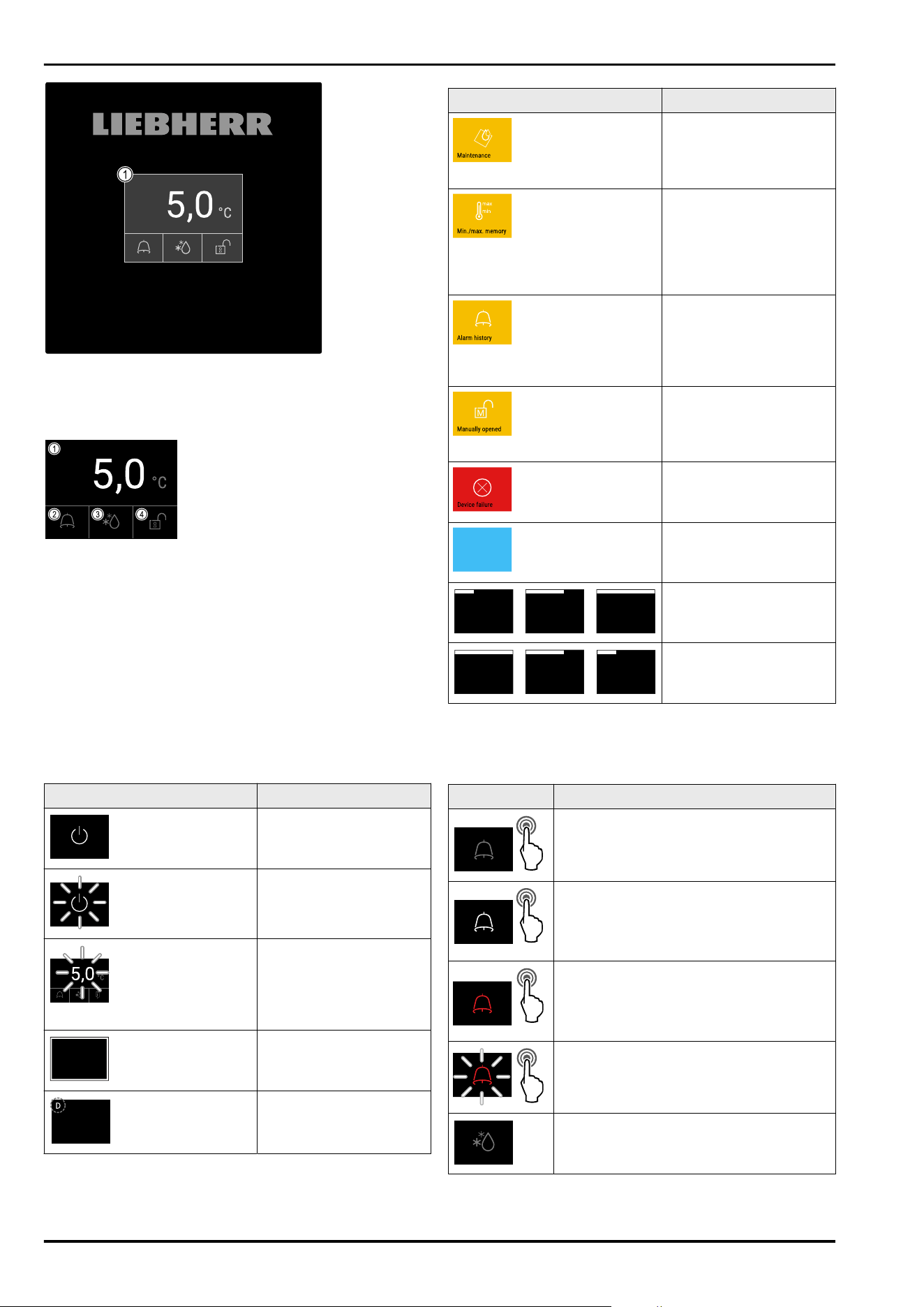
Fig. 89 Touch&Swipe display
(1)
Status display
7.1.1 Status display
Fig. 90 Status display
(1)
Actual temperature (3) Defrosting status
(2) Alarm status (4) Door locking status
The status display is the output display.
It displays the temperature in the middle and three symbols
in the lower area. The status display can show other display
symbols.
Navigation to the functions takes place from the status
display.
7.1.2 Display symbols
Display symbols provide information about the status of the
appliance.
Symbol
Appliance status
Standby symbol
Appliance is switched off.
Standby symbol
(flashing)
Appliance is starting up.
Temperature (flashing)
Target temperature not
yet reached. Appliance
cooling to temperature
set.
Status display (white
frame)
Appliance is locked.
D in the display
The appliance is in demo
mode.
Symbol Appliance status
Maintenance indicator
(yellow)
The set time interval has
expired.
Data memory full
(yellow)
The data memory
(999 hours) is full. The
oldest data will be over‐
written from now on.
Memory full alarm
(yellow)
The alarm memory is full.
Delete individual alarms
or the entire memory.
Manual door opening
(yellow)
The locked door was
opened manually.
Error symbol (red)
Appliance is in error
state.
Background (blue)
Active setting or active
function
Bar (increasing)
Press for 3 seconds to
activate the setting.
Bar (decreasing)
Press for 3 seconds to
deactivate the setting.
Symbols on the status display
The additional symbols on the bottom of the status
display enable fast access to alarm information and details
regarding the appliance status.
Symbol
Appliance status
Alarm symbol (grey)
Alarm archive is empty.
Pressing briefly opens the alarm archive.
Alarm symbol (white)
There are confirmed alarms in the alarm
archive.
Pressing briefly opens the alarm archive.
Alarm symbol (red)
There are still unconfirmed alarms in the
alarm archive.
Pressing briefly opens the alarm archive.
Alarm symbol (red, flashing)
There is an active alarm in the archive.
Pressing briefly opens the alarm archive.
Defrosting symbol (grey)
No active defrosting process.
Controls
* Depending on model and options 23
Symbol Appliance status
Defrosting symbol (white, flashing)
Defrosting is active.
Tapping briefly opens the
appliance defrosting function.
(see 7.2.23 Defrosting )
Defrosting symbol (white)
Automatic defrosting is active. The func‐
tion cannot be cancelled.
Door lock symbol (white, closed)
The door lock is active.
Pressing briefly opens the code entry for
opening the door. (see 7.2.6Door lock )
Door lock symbol (white, open)
The door lock is inactive.
Brief press opens the code entry for
locking the door. (see 7.2.6Door lock )
Additional symbols on the status display
7.1.3 Acoustic signals
A signal sounds in the following cases:
-
If a function or a value is confirmed.
-
If a function or a value can either not be activated or not
deactivated.
-
As soon as an error occurs.
-
If there is an alarm message.
The alarms can be switched on and off in the customer
menu.
7.2 Appliance functions
7.2.1 Notes on the appliance functions
The appliance functions are set at the factory so that your
appliance is fully functional.
Before you alter, activate or deactivate the device functions,
make sure that the following requirements are met:
❑
You have read and understood the descriptions of
how the display works. (see 4 Functionality of the
Touch&Swipe display)
❑
You have familiarised yourself with the operating and
display elements of your appliance. (see 7.1 Control and
display elements)
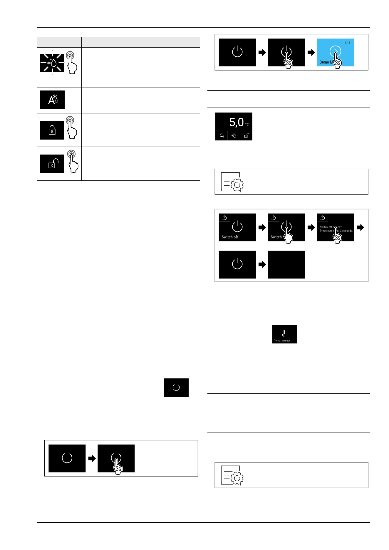
7.2.2 Switching appliance on and off
This function makes it possible to switch the entire appli‐
ance on and off.
Switching on appliance
If demo mode is not activated:
Fig. 91
► Carry out action steps according to the illustration.
If demo mode is activated:
Fig.92
► Carry out action steps according to the illustration.
Note
Deactivate demo mode before the countdown has finished.
Fig. 93 Status display
▷ The temperature appears in the display.
Switching off appliance
Fig. 94
Fig.95
► Carry out action steps according to the illustration.
▷ Standby symbol is shown in the display.
▷ The display switches off automatically after around
10 minutes.
7.2.3 Temperature
The temperature depends on the following factors:
-
How often the door is opened
-
How long the door is open for
-
The room temperature of the installation site
-
The type, temperature and amount of refrigerated food
Note
The temperature may differ from the temperature displayed
in some areas of the interior.
At the correct temperature, cooled produce will keep for
longer. This avoids disposing of food unnecessarily.
Setting temperature
The following steps describe how to increase the tempera‐
ture, e.g. from 12.1°C to 15.5°C.
Fig.96
Controls
24 * Depending on model and options
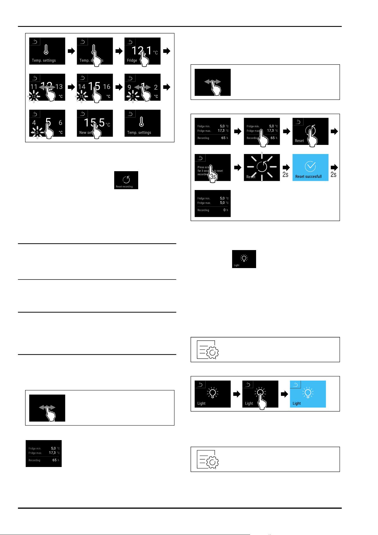
Fig.97
► Carry out action steps according to the illustration.
▷ Temperature is set.
7.2.4 Temperature recording
The appliance displays the minimum and maximum temper‐
atures of the interior via this function. The recording of
these temperatures starts automatically after the appliance
is switched on; they are recorded at one minute inter‐
vals. A note indicating that the data memory is full is
displayed after 999 hours (approx. 40 days). The tempera‐
ture recording should then be reset.
Note
The entire temperature history as well as alarm and service
messages are also recorded independently of this function.
This data can be exported and backed up on a USB storage
medium. (see 7.2.24Data download / Datalogging )
If there is an additional product sensor installed on the
appliance, there is the option of selecting this sensor
to display the minimum and maximum temperatures.
(see 7.2.25 Sensor calibration )
Note
The temperature recording should be reset once after
reaching the set temperature when the appliance is
commissioned. (see Resetting temperature recording) This
ensures that the value for the maximum temperature is a
meaningful value.
Displaying temperature recording
The temperature recording displays the length of the
recording and the minimum and maximum temperatures
measured during this period of time.
Fig.98
Fig.99
▷ Status screen with the temperature recordings is
displayed.
Resetting temperature recording
The displayed minimum and maximum temperatures can be
reset at any time. This deletes the displayed values and the
recording interval starts again.
Fig. 100
Fig. 101
► Carry out action steps according to the illustration.
▷ Temperature recording is reset.
7.2.5 Lighting
The appliance is fitted with interior lighting.
You can keep the interior lighting on continuously.
(see Switching on lighting*) *
When you open the appliance door, the interior lighting
switches on.
You can deactivate this function. (see Switching off the
lighting when opening the door*) *
Switching on lighting*
Fig. 102
Fig. 103
► Carry out action steps according to the illustration.
▷ Lighting is switched on.
Switching off lighting*
Fig. 104
Controls
* Depending on model and options 25
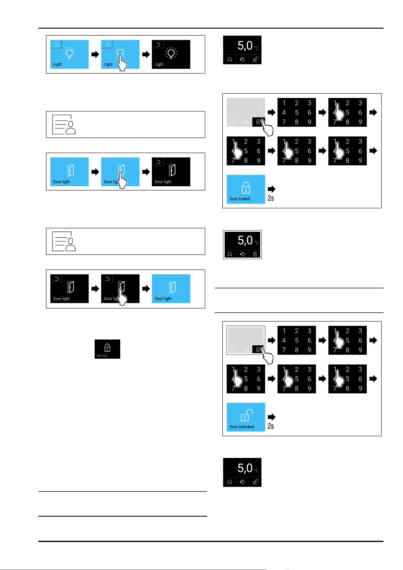
Fig. 105
► Carry out action steps according to the illustration.
▷ Lighting is switched off.
Switching off the lighting when opening the door*
Fig. 106
Fig. 107
► Carry out action steps according to the illustration.
▷ The lighting is switched off when the door is opened.
Switching on the lighting when opening the door*
Fig. 108
Fig. 109
► Carry out action steps according to the illustration.
▷ The lighting is switched on when the door is opened.
7.2.6 Door lock
The appliance is fitted with an electronic door lock. When
using the first time, the door is unlocked and you can open
it.
This function means the appliance can be secured against
the unwanted removal of items.
You have the following setting options for this:
-
Lock door using door code.
-
Unlock door using door code.
-
Activate automatic locking.
-
Deactivate automatic locking.
-
Set time delay for automatic locking.
-
Change the door code. (see 7.2.9Access codes)
-
Reset the door code. (see 7.2.9Access codes)
-
Pair remote control. (see 7.2.10 Remote control )
Locking door using door code
Note
► In the following example, the factory-set PIN
code:1111 is used.
Fig. 110 Status display
Starting from the status display, the door code entry begins
by pressing the open padlock symbol.
Fig. 111 Locking door using door code 1111.
► Carry out action steps according to the illustration.
Fig. 112 Status display with white border
▷ The door is locked.
Unlocking door using door code
Note
► In the following example, the factory-set PIN
code:1111 is used.
Fig. 114Unlock the door with door code 1111.
► Carry out action steps according to the illustration.
Fig. 115 Status display
▷ The status display with an open padlock symbol appears.
▷ The door is unlocked.
Controls
26 * Depending on model and options
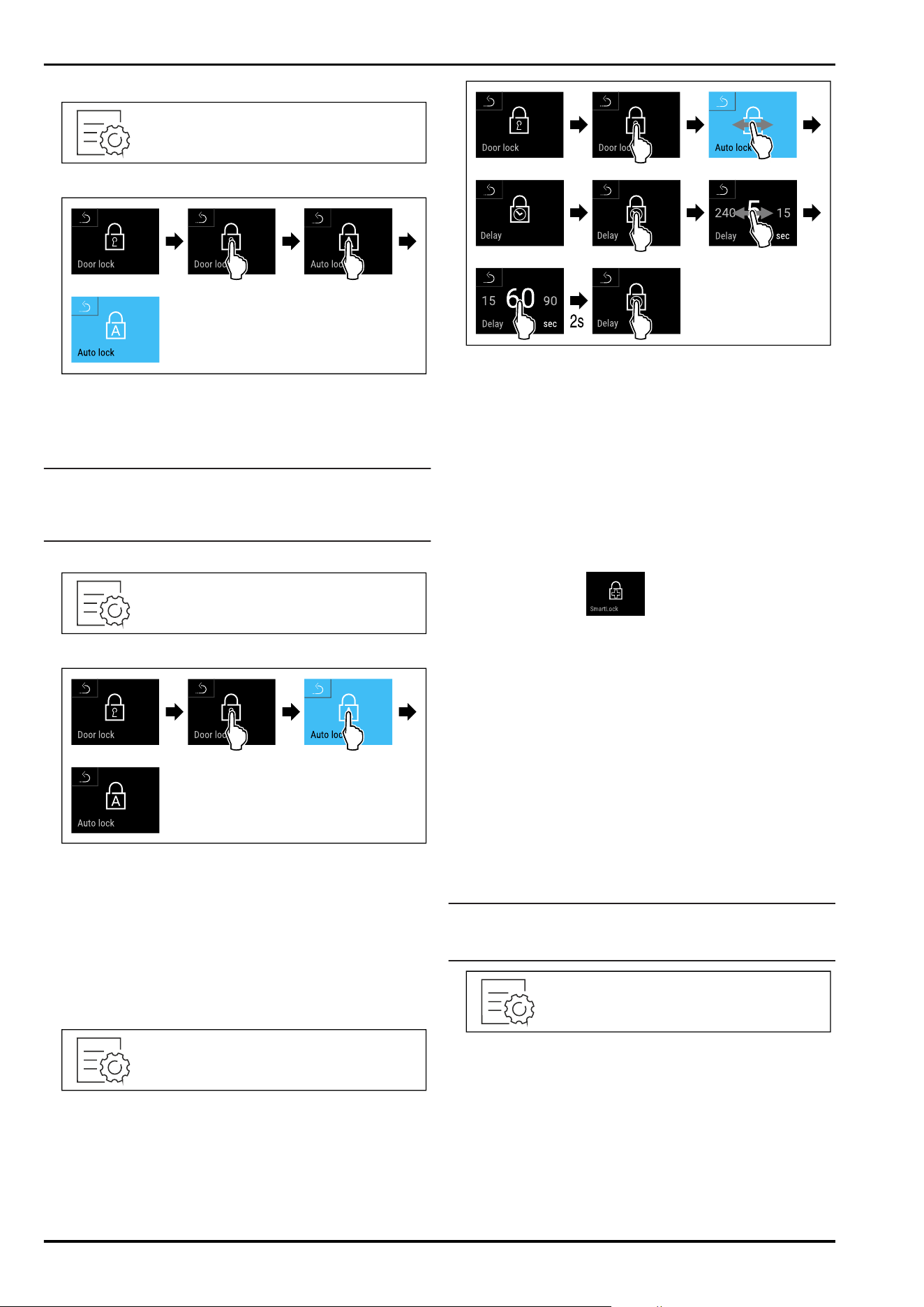
Activating automatic locking
Fig. 116
Fig.117
► Carry out action steps according to the illustration.
▷ Automatic locking is activated.
▷ The time delay (see Setting time delay for automatic
locking) can now be set.
Note
You can continue to lock and unlock the door using the
remote control (see 7.2.10 Remote control ) or by entering
the door code.
Deactivating automatic locking
Fig. 118
Fig. 119
► Carry out action steps according to the illustration.
▷ Automatic locking is deactivated.
Setting time delay for automatic locking
This function sets the time delay of the automatic door lock
after a door is opened.
Make sure that the following requirements are fulfilled:
❑
The automatic door locking (see Activating automatic
locking) is activated.
Fig.120
Fig. 121 The following values can be set: 5, 15, 60, 90, 120,
180 and 240 seconds
► Carry out action steps according to the illustration.
▷ Time delay is set.
Changing door code
(see 7.2.9Access codes)
Resetting door code
(see 7.2.9Access codes)
Pairing remote control
(see 7.2.10 Remote control )
7.2.7 SmartLock
To prevent the removal of the cooled produce, this func‐
tion enables automatic door locking after the temperature
alarm has been triggered. (see 7.2.26 Temperature alarm )
The locking delay time can be set. The door can then only be
opened with the SmartLock PIN code.
Application:
-
Activating the SmartLock.
-
Deactivating the SmartLock.
-
Setting the locking delay.
-
Unlocking the door lock with the SmartLock PIN code.
-
Changing the SmartLock PIN code. (see 7.2.9 Access
codes)
-
Resetting the SmartLock PIN code. (see 7.2.9 Access
codes)
Activating SmartLock
Note
► In the following example, the factory-set PIN
code:1111 is used.
Fig.122
Controls
* Depending on model and options 27
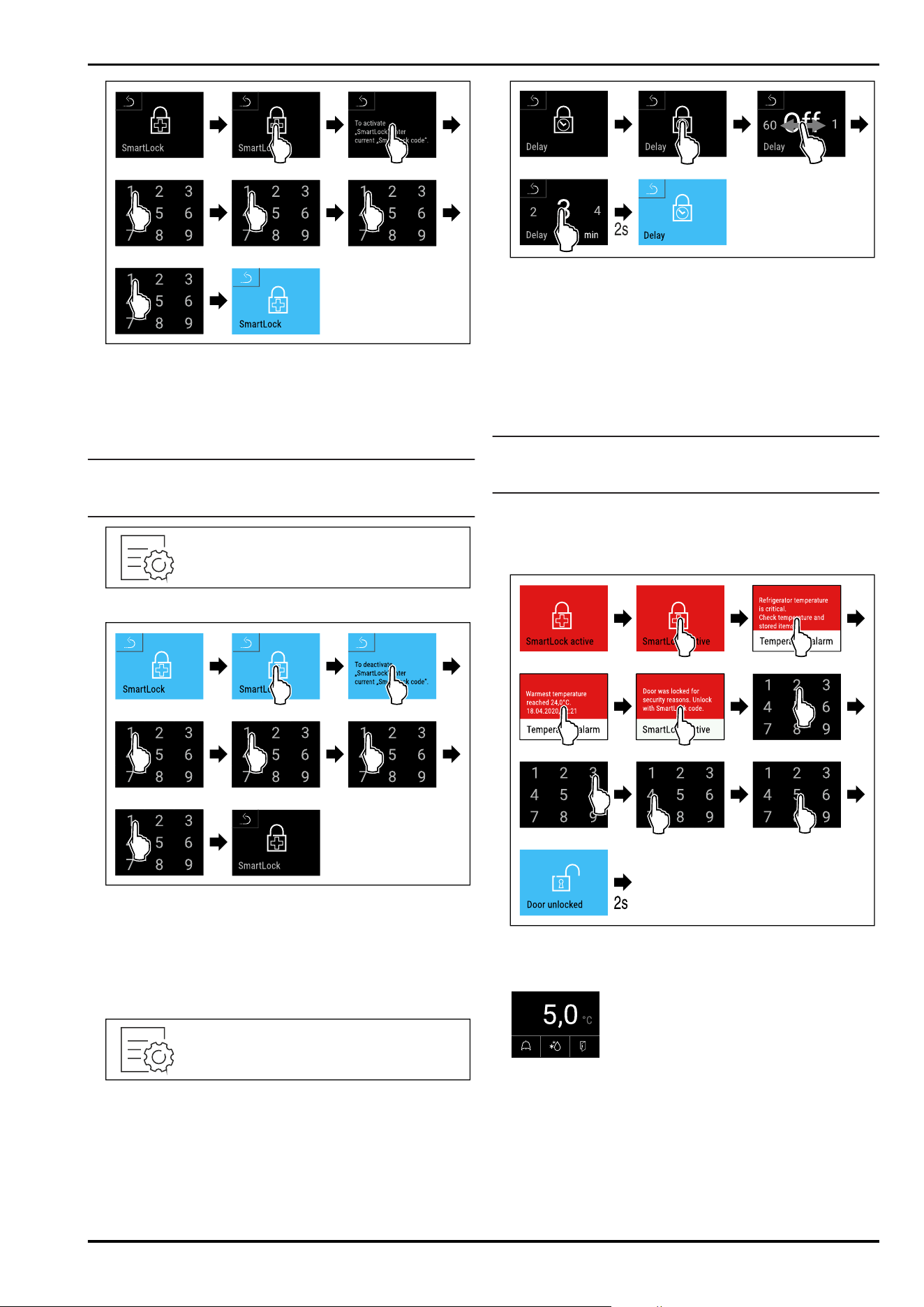
Fig.123
► Carry out action steps according to the illustration.
▷ SmartLock is activated.
▷ The locking delay interval can now be selected.
(see Setting locking delay)
Deactivating SmartLock
Note
► In the following example, the factory-set PIN
code:1111 is used.
Fig. 124
Fig.125
► Carry out action steps according to the illustration.
▷ SmartLock is deactivated.
Setting locking delay
Make sure that the following requirements are fulfilled:
❑
SmartLock must be activated. (see Activating SmartLock)
Fig. 126
Fig. 127 The following values can be set: Off (no waiting
time) up to 60 minutes; in 1-minute increments
► Carry out action steps according to the illustration.
▷ The time for the locking delay has been set.
Unlocking door lock with SmartLock PIN code
After the temperature alarm has been triggered
(see 7.2.26 Temperature alarm ) the door is locked automati‐
cally via the SmartLock function.
Opening is now only possible with the SmartLock PIN code.
Note
► In the following example, this SmartLock PIN code is
used:2345
Entry of the SmartLock PIN code starts from the status
display. Information about the SmartLock function and
the temperature recording for the temperature alarm are
displayed.
Fig.128
► Carry out action steps according to the illustration.
▷ The door is unlocked.
Fig. 129 Status display
▷ The temperature appears in the display.
Changing the SmartLock PIN code
(see 7.2.9Access codes)
Resetting the SmartLock PIN code
(see 7.2.9Access codes)
Controls
28 * Depending on model and options
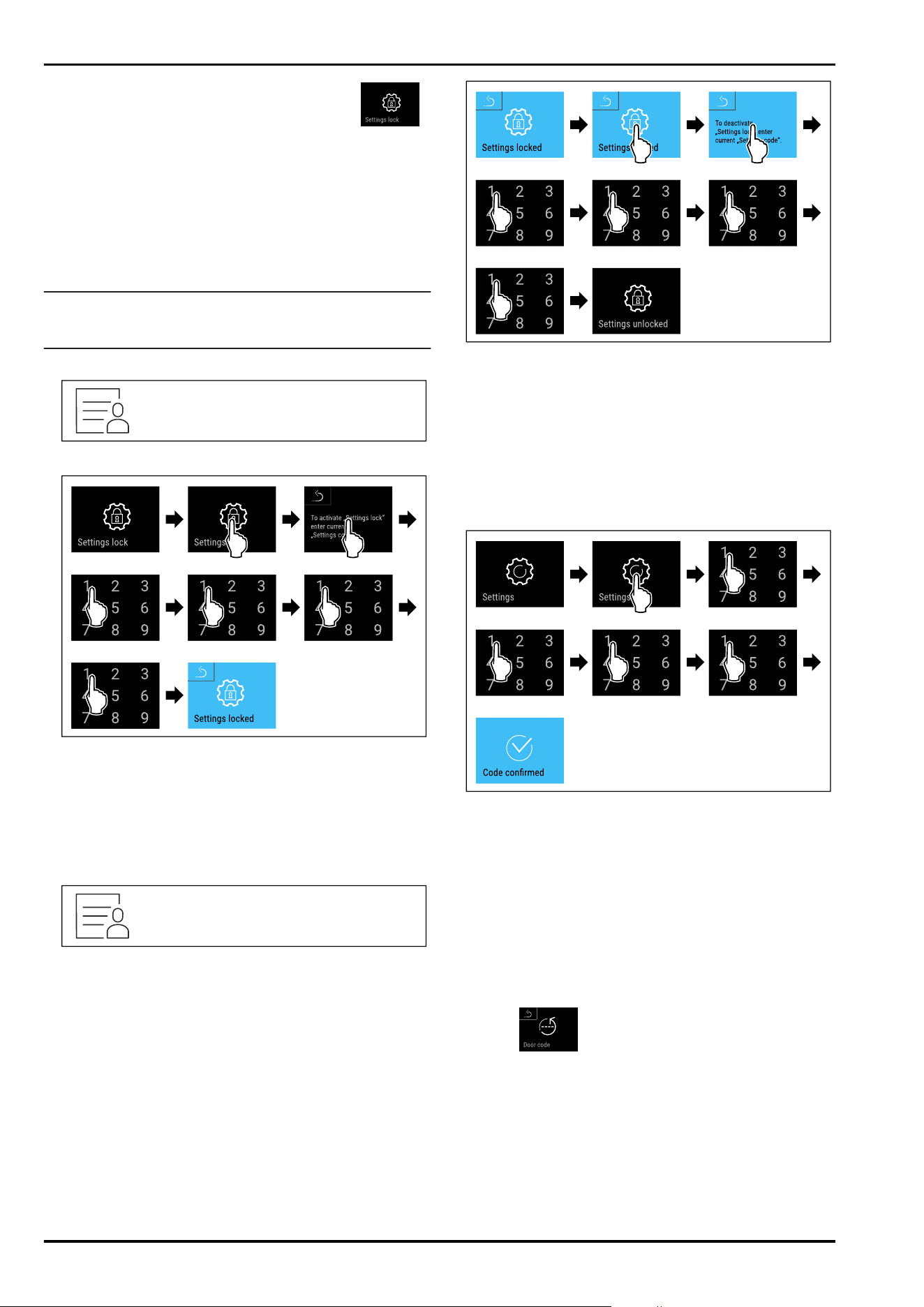
7.2.8 Settings menu access protection
This function enables the settings menu access protection
via a four-digit PIN code.
Application:
-
Prevent settings and functions being changed uninten‐
tionally.
-
Prevent appliance being switched off unintentionally.
-
Prevent temperature being set unintentionally.
Note
► In the following examples, the factory-set PIN
code:1111 is used.
Activating the settings menu access protection
Fig.130
Fig.131
► Carry out action steps according to the illustration.
▷ Settings menu access protection is activated.
Changing the access protection PIN code for the settings
menu
(see 7.2.9Access codes)
Deactivating the settings menu access protection
Fig.132
Fig.133
► Carry out action steps according to the illustration.
▷ Settings menu access protection is deactivated.
Opening protected settings menu
If the settings menu access protection is active, you must
enter the PIN code in order to be able to open the settings
menu. As soon as you exit the settings menu, the access
protection re-activates automatically.
► Swipe left or right until corresponding function is
displayed.
Fig.134
► Carry out action steps according to the illustration.
▷ PIN code is correct: settings menu opens.
7.2.9 Access codes
Access codes are required for some functions. You can only
use the following functions after entering the appropriate
access code:
-
Door lock
-
Settings menu
-
SmartLock
Door code
This function allows the door lock code to be changed or
reset.
Changing the door code
The door code can be changed in three steps:
- Enter old door code.
- Enter new door code.
- Confirm new door code.
Controls
* Depending on model and options 29

Note
In the following example, you change the factory-set door
code1111 to the new door code2345.
Fig.135
Fig.136
► Carry out action steps according to the illustration.
▷ Entering the old door code is successful.
Fig.137
► Carry out action steps according to the illustration.
▷ The new door code has been successfully entered.
Fig.138
► Carry out action steps according to the illustration.
▷ Confirmation of the new door code is successful.
▷ The door code has been changed.
► Re-pair the remote control. (see 7.2.10 Remote control )
Resetting the door code
If you no longer know the door code, you can reset it.
► Reset appliance to factoy settings. (see 7.2.33 Resetting
to factory settings )
▷ The appliance has been reset to its original settings.
▷ The factory-set door code is:1111
Access code for the settings menu
This function allows the access code for the settings menu
to be changed or reset.
Changing the access code for the settings menu
The access code can be changed in three steps:
- Enter old access code.
- Enter new access code.
- Confirm new access code.
Note
In the following example, you change the factory-set access
code1111 to the new access code2345.
Fig. 139
Access protection for the settings menu must be active.
(see 7.2.8 Settings menu access protection )
► Swipe left or right until corresponding function is
displayed.
Controls
30 * Depending on model and options
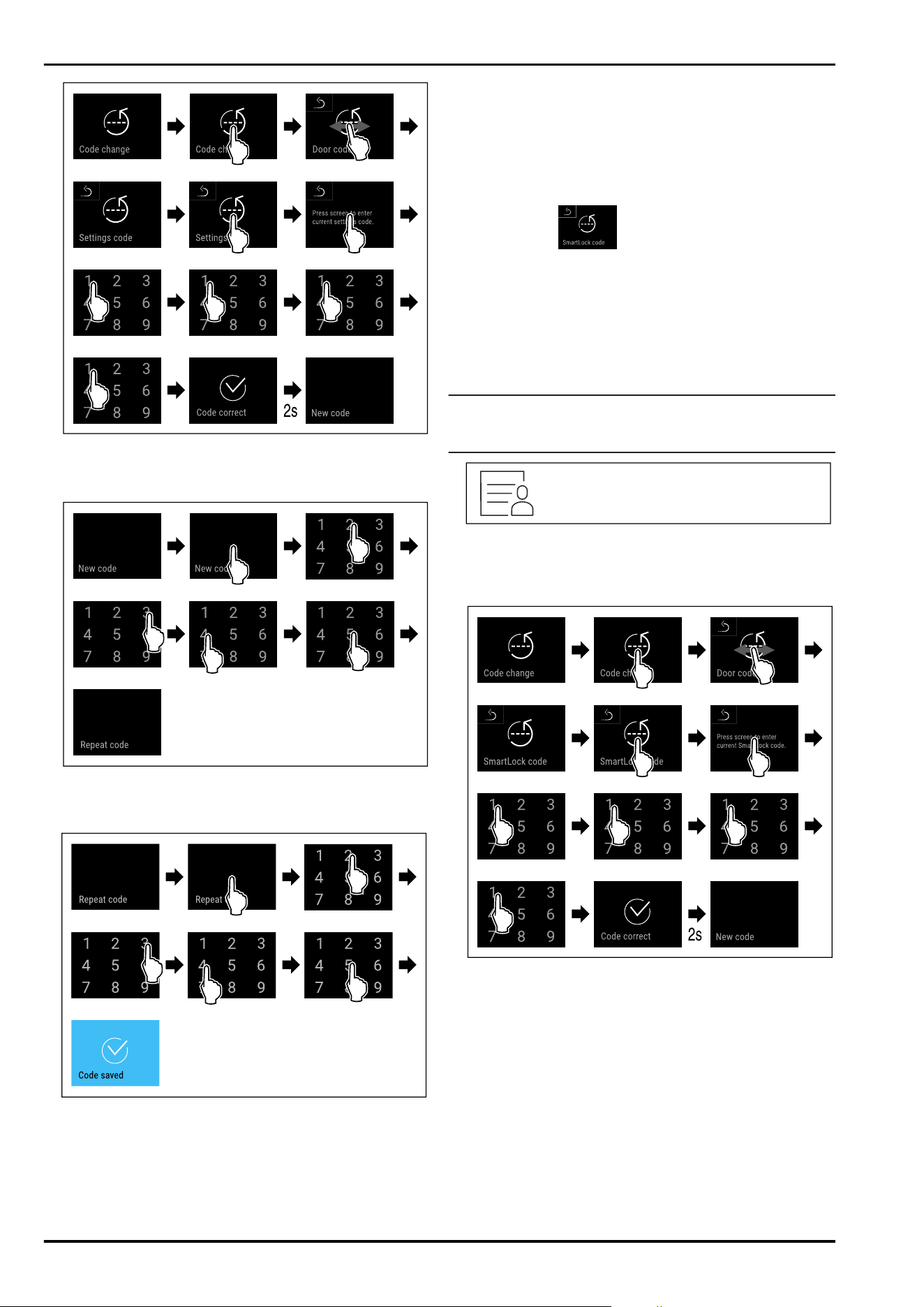
Fig. 140
► Carry out action steps according to the illustration.
▷ Entering the old access code is successful.
Fig. 141
► Carry out action steps according to the illustration.
▷ The new access code has been successfully entered.
Fig. 142
► Carry out action steps according to the illustration.
▷ Confirmation of the new access code is successful.
▷ The access code for the settings menu has been
changed.
Resetting the access code for the settings menu
If you no longer know the access code for the settings
menu, you can reset it.
► Reset appliance to factory settings (see 7.2.33 Resetting
to factory settings ) .
▷ The appliance has been reset to its original settings.
▷ The factory-set access code is:1111
SmartLock code
This function allows the SmartLock code to be changed or
reset.
Changing SmartLock code
The SmartLock-Code can be changed in three steps:
- Enter old SmartLock code.
- Enter new SmartLock code.
- Confirm new SmartLock code.
Note
In the following example, you change the factory-set Smart‐
Lock code1111 to the new SmartLock code2345.
Fig. 143
SmartLock must be active. (see 7.2.7 SmartLock )
► Swipe left or right until corresponding function is
displayed.
Fig. 144
► Carry out action steps according to the illustration.
▷ Entering the old SmartLock code is successful.
Controls
* Depending on model and options 31
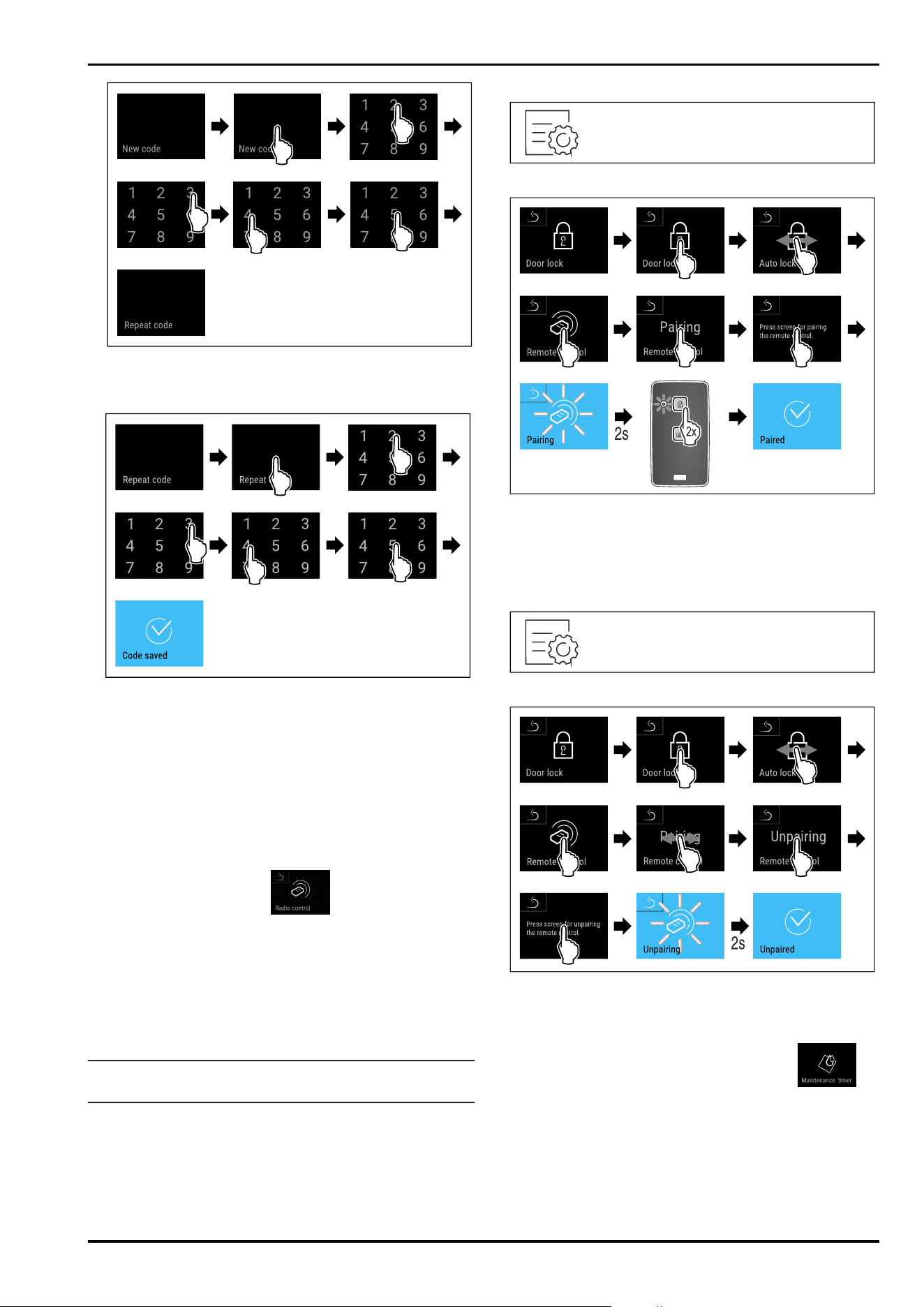
Fig. 145
► Carry out action steps according to the illustration.
▷ The new SmartLock code has been successfully entered.
Fig. 146
► Carry out action steps according to the illustration.
▷ Confirmation of the new SmartLock code is successful.
▷ The SmartLock code has been changed.
Resetting SmartLock code
If you no longer know the SmartLock code, you can reset it.
► Reset appliance to factory settings. (see 7.2.33 Resetting
to factory settings )
▷ The appliance has been reset to its original settings.
▷ The factory-set SmartLock code is:1111
7.2.10 Remote control
When supplied, a factory PIN code is stored on the remote
control. This opens every appliance with factory settings
unchanged (see 7.2.33 Resetting to factory settings ) . This
means multiple appliances can be opened and closed with
just one remote control. Pairing generates an appliance-
specific PIN code which can only open and close the appli‐
ance which is signed in. A factory reset restores the original
functionality.
Note
The range of the remote control is approximately 15m.
Application:
-
Pairing remote control.
-
Unpairing remote control.
Pairing remote control
Fig. 147
Fig. 148
► Carry out action steps according to the illustration.
► Press a button on the remote control twice.
▷ The status LED on the remote control flashes three times.
▷ The remote control is connected to the appliance.
Unpairing remote control
Fig. 149
Fig. 150
► Carry out action steps according to the illustration.
▷ The remote control is disconnected from the appliance.
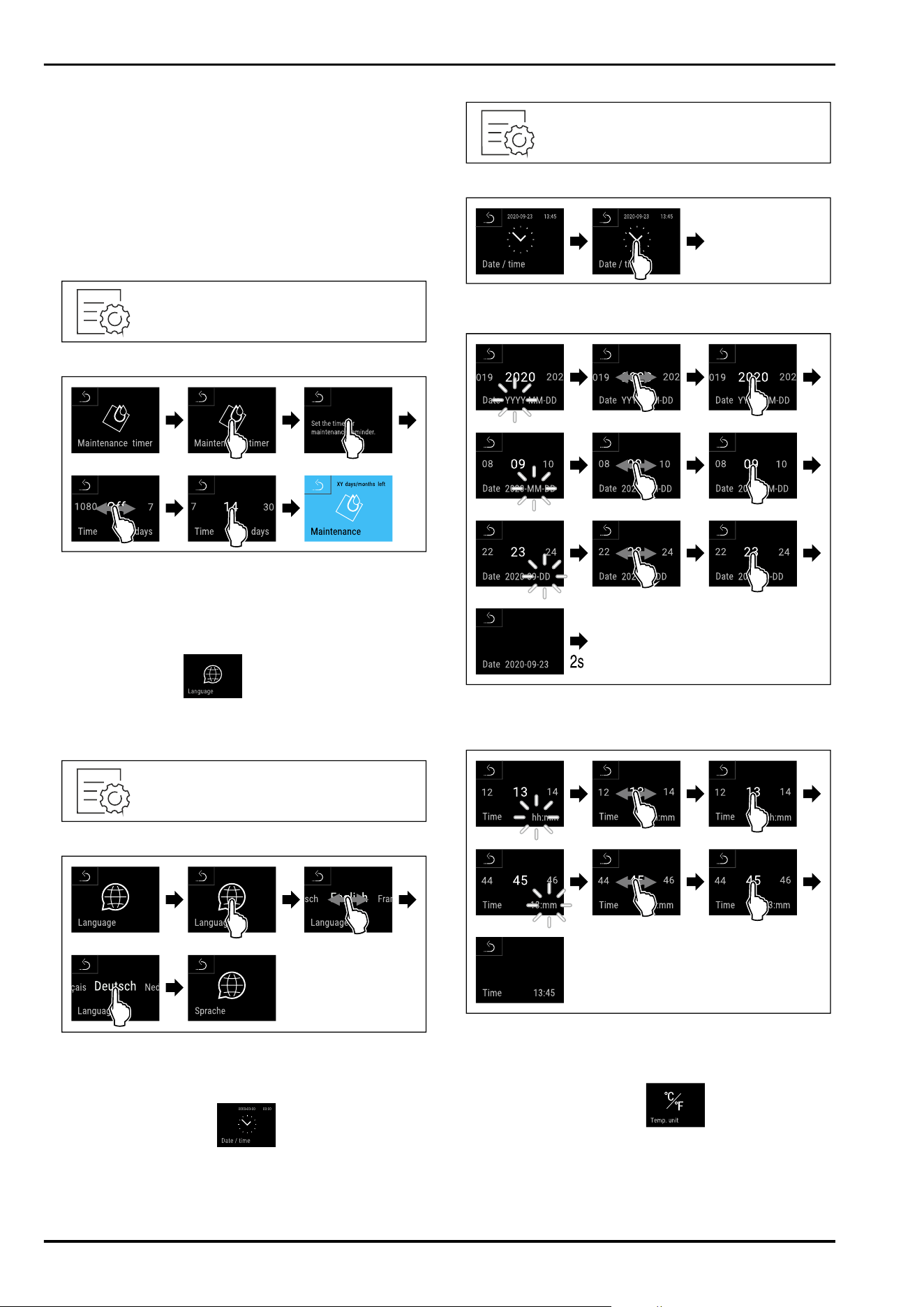
7.2.11 Maintenance interval reminder
Setting for the time interval after which a maintenance
reminder is issued.
The following values can be set:
-
7 days
-
14 days
-
30 days
Controls
32 * Depending on model and options
-
60 days
-
90 days
-
180 days
-
360 days
-
720 days
-
1080 days
-
Off
Setting maintenance interval reminder
The following steps describe how the maintenance interval
is set.
Fig. 151
Fig. 152
► Carry out action steps according to the illustration.
▷ The time interval, after which the maintenance reminder
is issued, is set.
▷ The remaining time is displayed.
7.2.12 Language
This setting allows the display language to be set.
Setting language
Fig. 153
Fig. 154
► Carry out action steps according to the illustration.
▷ The selected language is set.
7.2.13 Date and time
This setting makes it possible to set the date and time.
Setting date and time
Fig. 155
Fig. 156
► Carry out action steps according to the illustration.
Fig. 157
► Carry out action steps according to the illustration.
▷ Date has been set.
Fig. 158
► Carry out action steps according to the illustration.
▷ Time has been set.
7.2.14 Temperature unit
Use this function to set the temperature unit. You can set
degrees Celsius or degrees Fahrenheit as the temperature
unit.
Controls
* Depending on model and options 33
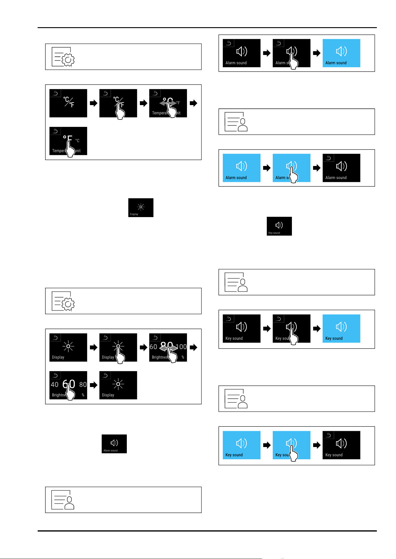
Setting the temperature unit
Fig. 159
Fig. 161 Example illustration: Switch from degreesCelsius
to degrees Fahrenheit.
► Carry out action steps according to the illustration.
▷ The temperature unit is set.
7.2.15 Display brightness
Use this function to set the display brightness in stages.
You can select the following brightness levels:
-
40%
-
60%
-
80%
-
100 % (pre-setting)
Setting the brightness
Fig. 162
Fig. 163 Example illustration: Switch from 80 % to 60%.
► Carry out action steps according to the illustration.
▷ The brightness is set.
7.2.16 Alarm tone
This function enables all alarm sounds, such as door
alarms, to be switched on and off.
Activating the alarm tone
Fig. 164
Fig. 165
► Carry out action steps according to the illustration.
▷ The alarm tone is activated.
Deactivating the alarm tone
Fig. 166
Fig. 167
► Carry out action steps according to the illustration.
▷ The alarm tone is deactivated.
7.2.17 Key tone
This function makes it possible to switch all button sounds,
confirmation sounds, and the startup sound on and off.
Activating the key tone
Fig. 168
Fig. 169
► Carry out action steps according to the illustration.
▷ The key tone is activated.
Deactivating the key tone
Fig.170
Fig.171
► Carry out action steps according to the illustration.
▷ The key tone is deactivated.
Controls
34 * Depending on model and options
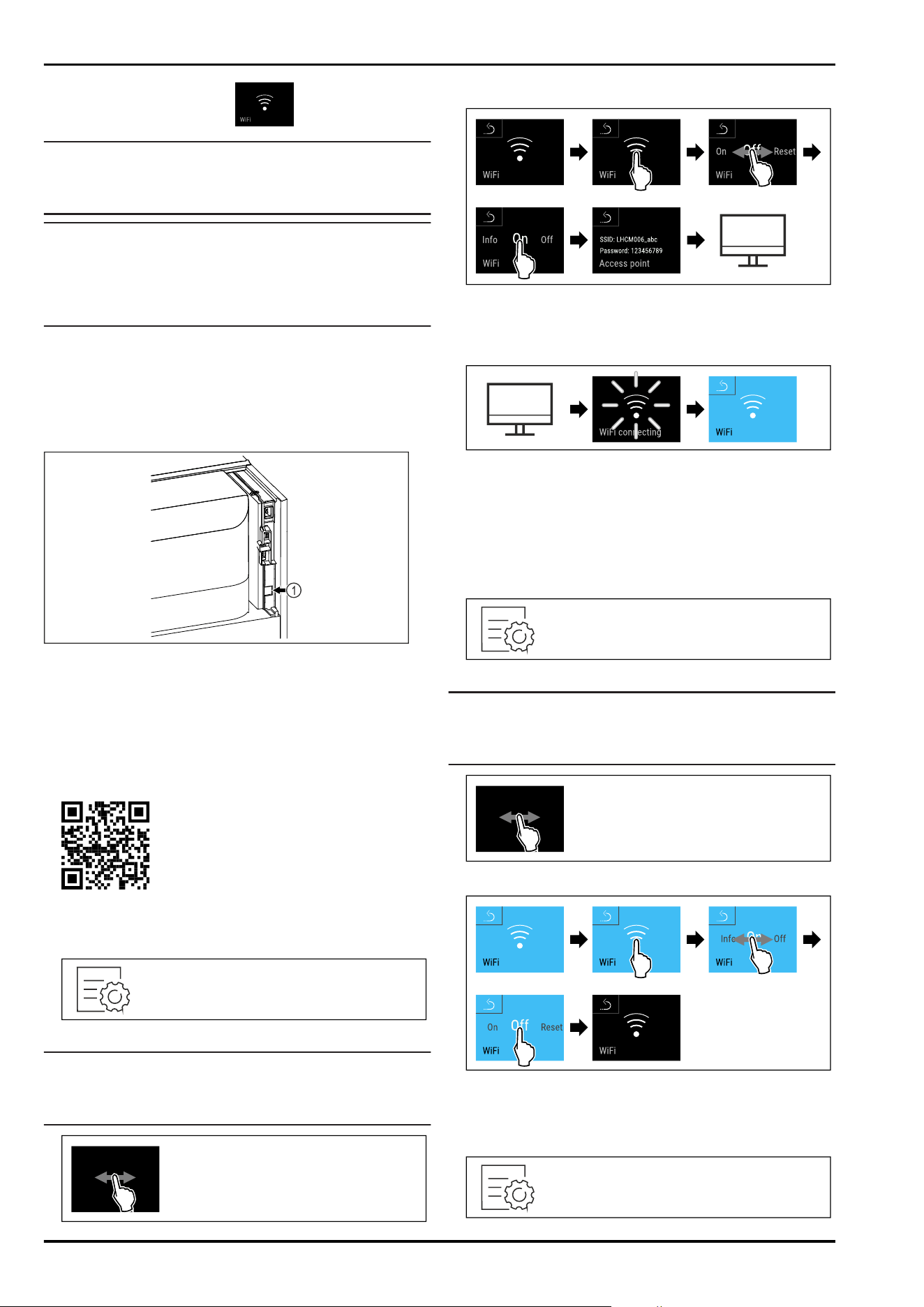
7.2.18 WiFi connection
Note
Liebherr SmartMonitoring Dashboard is not available in all
countries. Check availability via the QR code by entering
your model.
Note
Use of the Liebherr SmartMonitoring Dashboard at https://
smartmonitoring.liebherr.com requires installation of a
SmartModule and a commercial MyLiebherr account. When
commissioning online you can register using the login data
you have, or register again and create a company account.
This setting establishes a wireless connection between the
appliance and the internet. The connection is controlled via
the SmartModule. The appliance can be integrated via the
browser-based Liebherr SmartMonitoring Dashboard and
advanced options as well as customised methods relating
to control, administration and monitoring can be used.
Fig.172
Make sure that the following requirements are fulfilled:
❑
SmartModule Fig.172(1) is in use.
Establishing connection
You commission and set up your SmartModule online via the
Liebherr SmartMonitoring Dashboard on your web-enabled
device.
Fig.173
► Open Liebherr SmartMonitoring Dashboard. (see Fig. 173)
On the refrigerator or freezer:
Fig. 174
Note
The settings menu access protection is activated.
(see 7.2.8 Settings menu access protection )
► Enter the chosen PIN code. The settings menu opens.
Fig.175
Fig. 176
► Carry out action steps according to the illustration.
► Continue the set-up procedure on your web-enabled
device: Liebherr SmartMonitoring Dashboard
Fig.177
► Carry out action steps according to the illustration.
▷ Connection is established: WiFi connecting appears. The
symbol flashes.
► Follow the Liebherr SmartMonitoring Dashboard instruc‐
tions.
▷ Connection is established.
Disconnecting
Fig.178
Note
The settings menu access protection is activated.
(see 7.2.8 Settings menu access protection )
► Enter the chosen PIN code. The settings menu opens.
Fig.179
Fig. 180
► Carry out action steps according to the illustration.
▷ There is no connection.
Resetting connection
Controls
* Depending on model and options 35
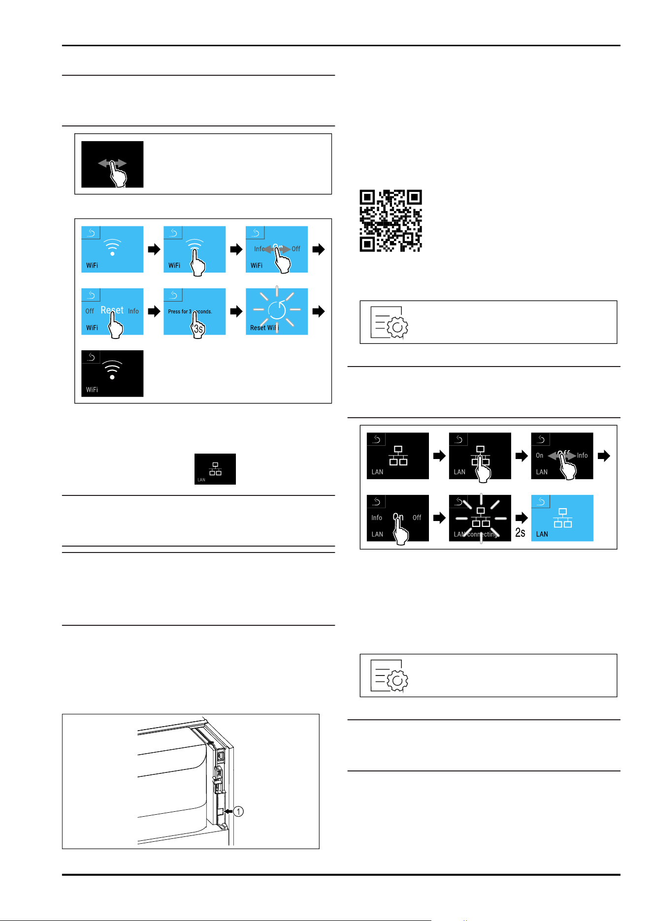
Fig. 181
Note
The settings menu access protection is activated.
(see 7.2.8 Settings menu access protection )
► Enter the chosen PIN code. The settings menu opens.
Fig. 182
Fig. 183
► Carry out action steps according to the illustration.
▷ The WiFi settings are restored to the factory settings.
7.2.19 LAN connection
Note
Liebherr SmartMonitoring Dashboard is not available in all
countries. Check availability via the QR code by entering
your model.
Note
Use of the Liebherr SmartMonitoring Dashboard at https://
smartmonitoring.liebherr.com requires installation of a
SmartModule and a commercial MyLiebherr account. When
commissioning online you can register using the login data
you have, or register again and create a company account.
This setting establishes a wired connection between the
appliance and the internet. The connection is controlled via
the SmartModule. The appliance can be integrated via the
browser-based Liebherr SmartMonitoring Dashboard and
advanced options as well as customised methods relating
to control, administration and monitoring can be used.
Fig. 184
Make sure that the following requirements are fulfilled:
❑
SmartModule Fig. 184(1) is in use.
❑
A network cable is connected.
❑
The network is connected to the internet.
Establishing connection
You commission and set up your SmartModule online via the
Liebherr SmartMonitoring Dashboard on your web-enabled
device.
Fig. 185
► Open Liebherr SmartMonitoring Dashboard. (see Fig. 185)
On the refrigerator or freezer:
Fig. 186
Note
The settings menu access protection is activated.
(see 7.2.8 Settings menu access protection )
► Enter the chosen PIN code. The settings menu opens.
Fig. 187
► Carry out action steps according to the illustration.
▷ Connection is established: LAN connecting appears. The
symbol flashes.
► Follow the Liebherr SmartMonitoring Dashboard instruc‐
tions.
▷ Connection is established.
Disconnecting
Fig. 188
Note
The settings menu access protection is activated.
(see 7.2.8 Settings menu access protection )
► Enter the chosen PIN code. The settings menu opens.
Controls
36 * Depending on model and options
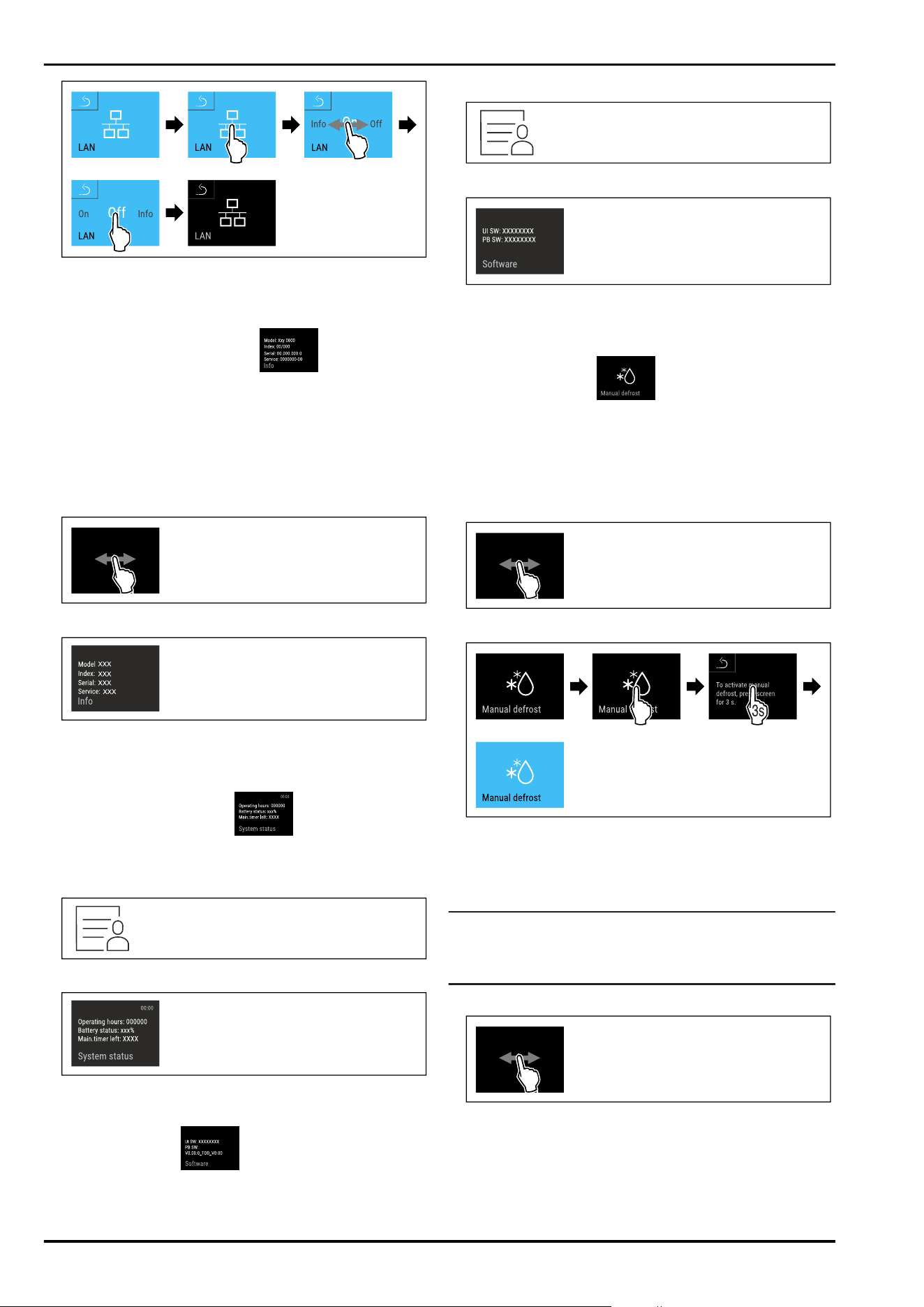
Fig. 189
► Carry out action steps according to the illustration.
▷ There is no connection.
7.2.20 Device information
Use this function to indicate the model name, index, serial
number and service number of your device. You will need
the device information when you contact customer service.
(see 10.3 Customer Service)
This function also opens the Advanced menu. (see 4 Func‐
tionality of the Touch&Swipe display)
Indicating the device information
Fig. 190
Fig. 191
► Carry out action steps according to the illustration.
▷ Display indicates device information.
7.2.21 Operating hours
The display shows the appliance operating hours.
Displaying operating hours
Fig. 192
Fig. 193
▷ The operating hours appear.
7.2.22 Software
Use this function to indicate the software version of your
device.
Indicating the software version
Fig. 194
Fig. 195
► Carry out action steps according to the illustration.
▷ Display indicates software version.
7.2.23 Defrosting
The appliance defrosts automatically in normal operation.
Application:
-
If there is heavy icing in the interior, the automatic
defrosting function can be started manually.
Starting automatic defrosting manually
Fig. 196
Fig. 197
► Carry out action steps according to the illustration.
▷ Automatic defrosting is started. When the defrosting
process is complete, the appliance automatically
switches back to normal operation.
Note
If there is still ice in the interior after the automatic
defrosting has been started several times, defrost the appli‐
ance manually. (see 9.2 Defrosting appliance)
Cancelling a manually started defrosting
Fig. 198
Controls
* Depending on model and options 37
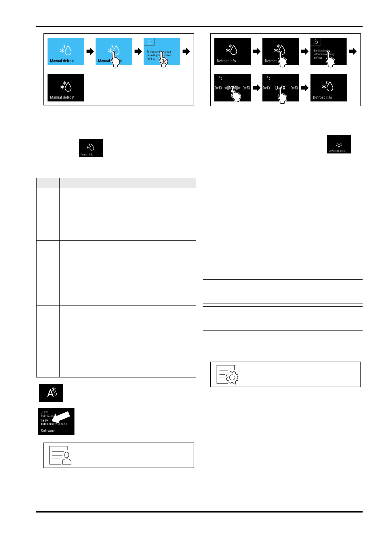
Fig. 199
► Carry out action steps according to the illustration.
▷ Manually started defrosting is cancelled. The appliance
automatically switches back to normal operation.
Defrosting info
This setting adjusts the display during an automatic
defrosting.
Display
Description
Def1 The temperature display is not being updated. It
shows the last temperature before the automatic
defrosting process started.
Def2 “Automatic defrosting” icon is indicated on the
status display. The temperature display is contin‐
uously updated and displays the actual tempera‐
ture.
Def3 With software
version PW SW
lower than
TOD8-800:
The temperature display is not
being updated. It shows the last
temperature before the auto‐
matic defrosting process started.
With software
version PW SW
equal to or
higher than
TOD8-800:
The temperature display is
continuously updated and
displays the actual temperature.
Def4 With software
version PW SW
lower than
TOD8-800:
The temperature display is not
being updated. It shows the last
temperature before the auto‐
matic defrosting process started.
With software
version PW SW
equal to or
higher than
TOD8-800:
“Automatic defrosting” notice is
indicated on the status display.
The temperature display is not
being updated. It shows the last
temperature before the auto‐
matic defrosting process started.
Display of the “automatic defrosting” in the
status display
Here you can see the software version
installed on your appliance PW SW:
(see 7.2.22 Software )
Fig.200
Fig.201
► Carry out action steps according to the illustration.
▷ The desired display variant is selected.
7.2.24 Data download / Datalogging
The appliance automatically records the entire temperature
history of various sensors as well as alarm and service
messages. The recording starts automatically after the
appliance is switched on and records at one minute inter‐
vals. The data for the past 5 years is stored and can be
downloaded onto a USB stick at any time.
The following data sets can be selected for download:
-
Temperatures
-
Alarms
-
Service messages
-
All
The selected data sets are stored in unencrypted format as
text files over the entire recording period; these files have
the extension „.log“.
Data download on USB stick
Note
Only USB memory sticks may be connected to the USB
interface. USB hard drives are not detected.
Note
Do not remove the USB storage stick during the download
procedure.
Make sure that the following requirements are fulfilled:
❑
USB 2.0 storage stick, FAT32 formatted.
❑
USB stick is connected.
Fig.202
Controls
38 * Depending on model and options
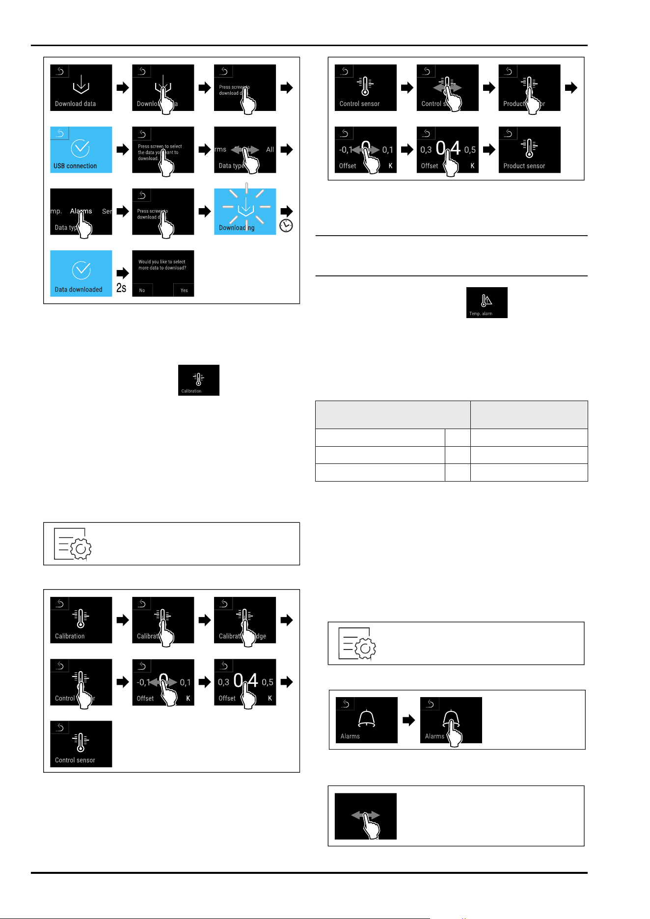
Fig.203
► Carry out action steps according to the illustration.
▷ Successful data download on USB stick.
▷ It is possible to select and download further data sets.
7.2.25 Sensor calibration
You can use sensor calibration to compensate for differ‐
ences between the set temperature and the actual existing
temperature. To do this, use calibrated measuring equip‐
ment to determine the actual existing temperature.
Setting range for C sensor (control sensor): +/- 3 Kelvin in
0.1 Kelvin increments.
Setting range for P sensor (product sensor): +/- 9.9 Kelvin in
0.1 Kelvin increments
Calibrating sensor
Fig.204
Fig.205
► Carry out action steps according to the illustration.
▷ C sensor has been calibrated.
Fig.206
► Carry out action steps according to the illustration.
▷ P sensor has been calibrated.
▷ Sensor calibration has been completed.
Note
The calibrated temperature is indicated on the display
within two hours.
7.2.26 Temperature alarm
Use this function to set the temperature alarm. You set
the upper and lower temperature limits with a differential
offset to the indoor temperature currently set. The tempera‐
ture alarm is triggered as soon as the indoor temperature
leaves the set temperature range and any set delay time
has elapsed.
Example
Differential value to be
set
Current indoor temperature 5°C
Lower temperature limit 2°C -3°C
Upper temperature limit 8°C +3°C
The following values can be set:
-
Differential value for lower temperature limit in 0.1 °C
steps
-
Differential value for upper temperature limit in 0.1 °C
steps
-
Alarm delay time from 0 to 60 minutes (setting “0” means
no temperature alarm delay.)
-
Alarm repetition frequency from 0 to 30 minutes (setting
“0” means no alarm repetition after confirming the
alarm.)
Setting temperature alarm
Fig.207
Fig.208
► Carry out action steps according to the illustration.
Controls
* Depending on model and options 39
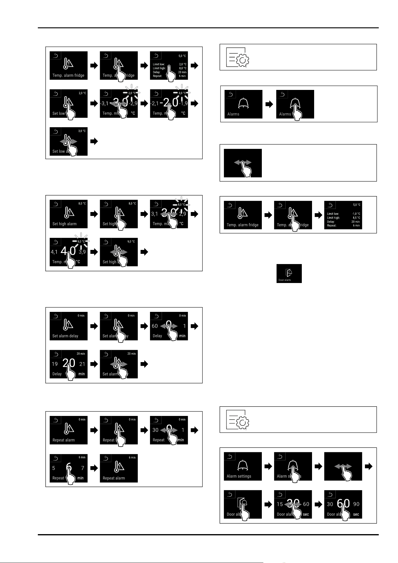
Fig.209
Fig. 210 Example of setting the lower temperature limit
based on a set appliance temperature of 5°C.
► Carry out action steps according to the illustration.
▷ Lower temperature limit has been set.
Fig. 211 Example of setting the lower temperature limit
based on a set appliance temperature of 5°C.
► Carry out action steps according to the illustration.
▷ Upper temperature limit has been set.
Fig.212
► Carry out action steps according to the illustration.
▷ Alarm delay time has been set.
Fig.213
► Carry out action steps according to the illustration.
▷ Alarm repetition interval has been set.
▷ Temperature alarm has been set.
Displaying set temperature alarm values
Fig. 214
Fig. 215
► Carry out action steps according to the illustration.
Fig. 216
Fig.217
► Carry out action steps according to the illustration.
▷ Set temperature alarm values are displayed.
7.2.27 Door alarm
Use this function to activate or deactivate the door alarm.
The door alarm sounds if the door is open for too long. The
door alarm is activated on delivery. You can set how long
the door may be open before the door alarm sounds.
The following values can be set:
-
15seconds
-
30seconds
-
60seconds
-
90seconds
-
120seconds
-
150seconds
-
180seconds
-
Off
Setting the door alarm
Fig. 218
Controls
40 * Depending on model and options
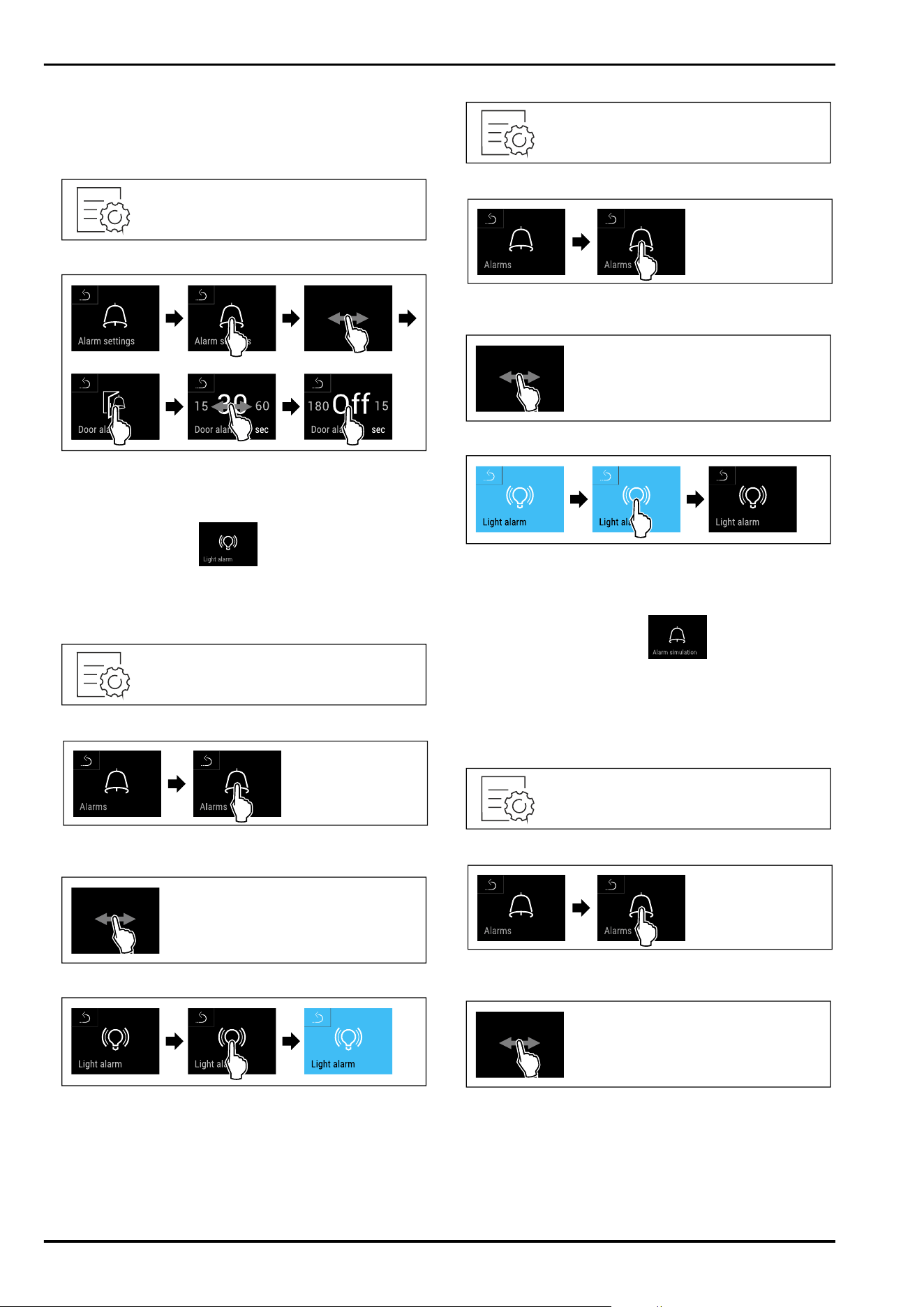
Fig. 220 Example illustration: Switch door alarm from
30 seconds to 60seconds.
► Carry out action steps according to the illustration.
▷ The door alarm is set.
Deactivating the door alarm
Fig.221
Fig.222
► Carry out action steps according to the illustration.
▷ The door alarm is deactivated.
7.2.28 Light alarm
This setting allows the visual alarm messages in the display
to also be emphasised by flashing appliance lighting.
Activating light alarm
Fig.223
Fig. 224
► Carry out action steps according to the illustration.
Fig.225
Fig. 226
► Carry out action steps according to the illustration.
▷ The light alarm is activated.
Deactivating light alarm
Fig.227
Fig.228
► Carry out action steps according to the illustration.
Fig.229
Fig.230
► Carry out action steps according to the illustration.
▷ The light alarm is activated.
7.2.29 Alarm simulation
You can use this function to simulate a temperature alarm in
the appliance, e.g. to check whether a safety device triggers
correctly. The safety device is connected to the potential-
free alarm output. (see 8.5 Interfaces)
Starting the alarm simulation
Fig.231
Fig.232
► Carry out action steps according to the illustration.
Fig.233
Controls
* Depending on model and options 41
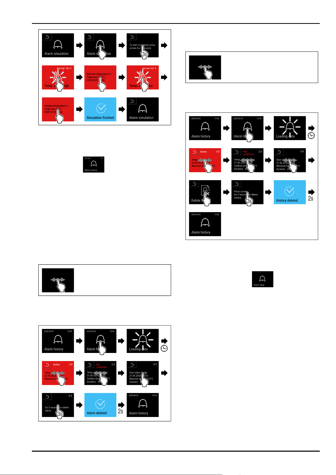
Fig.234
► Carry out action steps according to the illustration.
▷ The simulation has been performed.
▷ Connected safety devices should have triggered.
7.2.30 Alarm log
This setting makes it possible to query and delete the last
10 alarms that have occurred on the device.
The following is displayed:
-
Current date and time
-
Active alarms (red).
-
Past alarms, which have not yet been queried, are shown
as unconfirmed (red).
Confirmation is given by swiping to the next error.
-
Alarms, which have been queried, are shown as
confirmed.
-
Deletion of all alarms (including active and unconfirmed
alarms).
Displaying alarm log and deleting an alarm
Fig.235
-or-
► Via the display symbol at the bottom edge of the status
display.
Fig.236
► Carry out action steps according to the illustration.
▷
The querying and deletion of an alarm has been
performed.
Displaying alarm log and deleting all alarms
Fig.237
-or-
► Via the display symbol at the bottom edge of the status
display.
Fig.238
► Carry out action steps according to the illustration.
▷ The querying and deletion of all alarms has been
performed.
7.2.31 Alarm forwarding
You can use this function to forward one or several
alarms to an external alarm receiver. The alarm receiver is
connected to the potential-free alarm output on the appli‐
ance. (see 8.5 Interfaces)
You can select the following settings:
-
Alarm type:
•
Door alarm
•
Temperature alarm
•
Door alarm and temperature alarm
•
All
-
Confirm:
•
Yes: The alarm is confirmed on the appliance and the
external, connected receiver.
•
No: The alarm is confirmed on the appliance and
remains active on the receiver until the fault is recti‐
fied.
-
Refresh (only visible if you select “Yes” when confirming):
•
Yes: Alarm repeats.
Temperature alarm depending on the set time
(see 7.2.26 Temperature alarm )
Controls
42 * Depending on model and options
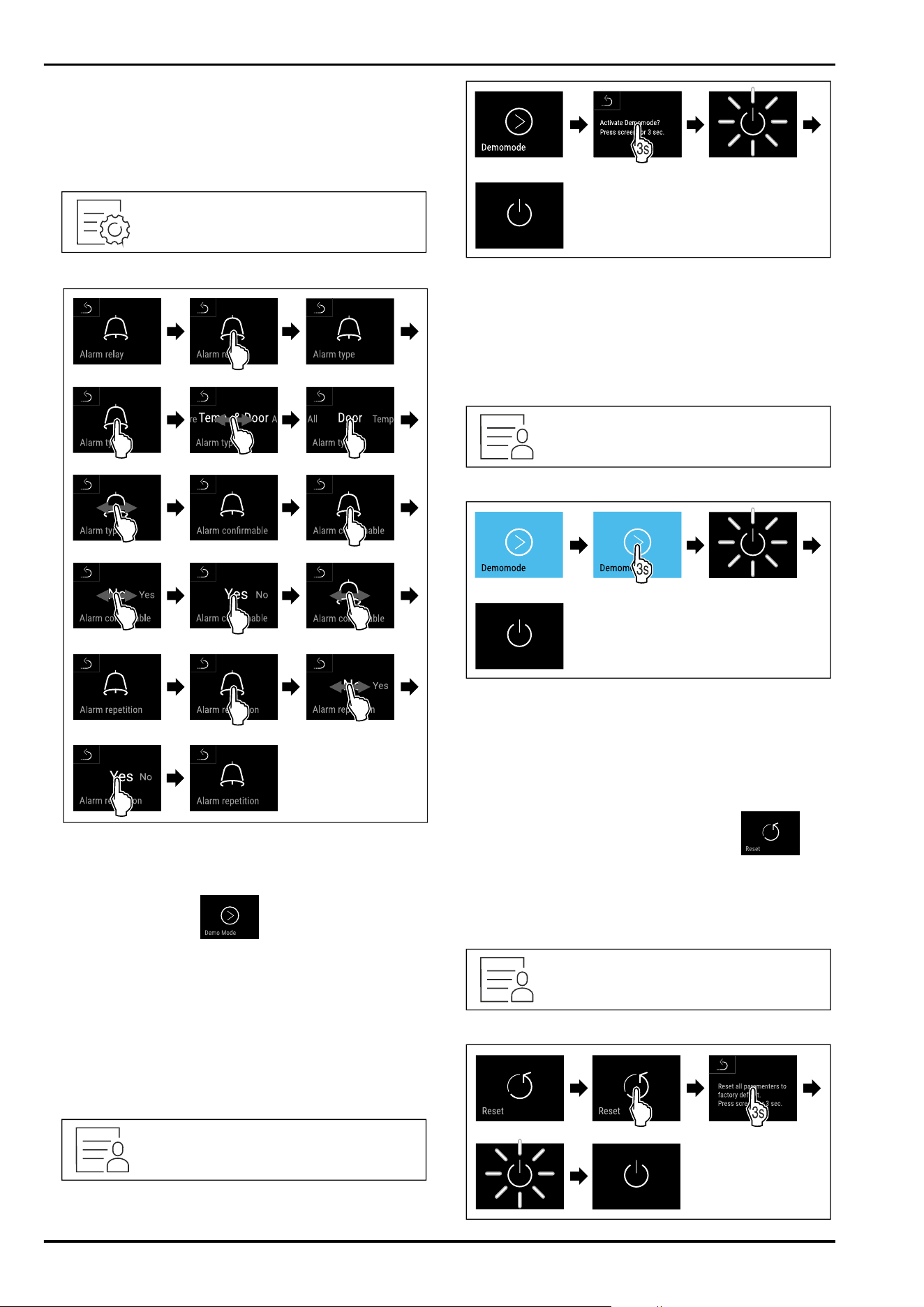
(If you set the alarm delay time to “0”, there is no
alarm repetition on the alarm relay.)
Door alarm after 1 or 4 minutes* (see 7.2.27 Door
alarm )
•
No: The alarm is confirmed permanently.
Activating alarm forwarding
Fig. 239
Fig. 240
► Carry out action steps according to the illustration.
▷ Alarm forwarding is set.
7.2.32 Demo mode
Demo mode is a special feature for dealers who want to
demonstrate appliance features. If you activate demo mode,
all refrigeration functions are deactivated.
If you switch on your appliance and a “D” appears on the
status display, demo mode is already activated.
If you activate and then deactivate demo mode, the appli‐
ance will be reset to factory defaults. (see 7.2.33 Resetting
to factory settings )
Activating demo mode
Fig. 241
Fig. 242
► Carry out action steps according to the illustration.
▷ Demo mode is activated.
▷ Appliance is switched off.
► Switch on the appliance. (see 5.1 Switching on appliance
(first use))
▷ “D” appears in the status display.
Deactivating demo mode
Fig. 243
Fig. 244
► Carry out action steps according to the illustration.
▷ Demo mode is deactivated.
▷ Appliance is switched off.
► Switch on the appliance. (see 5.1 Switching on appliance
(first use))
▷ Appliance is reset to factory settings.
7.2.33 Resetting to factory settings
Use this function to reset all settings to factory defaults.
All settings you have made so far are reset to their original
settings.
Performing a reset
Fig. 245
Controls
* Depending on model and options 43
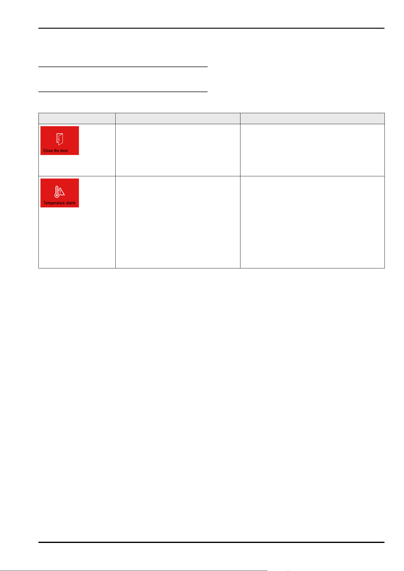
Fig. 246
► Carry out action steps according to the illustration.
▷ Device is reset.
▷ Device is switched off.
Note
To reset to factory settings in battery mode: Restart is only
possible with mains voltage.
► Restart the device. (see 5.1 Switching on appliance (first
use))
7.3 Message
7.3.1 Warnings
Warnings are issued by means of an acoustic signal and
visually via a symbol on the display. The signal gets louder
until the warning is acknowledged.
Message (red) Cause Remedy
Door open
This message appears if the door is open
for too long.
Close the door.
Tap briefly.
Alarm is stopped.
Note
The time until the message appears can be set.
(see 7.2.27Door alarm )
Temperature alarm
This message appears if the temperature
does not match the set temperature.
Reasons for differences in temperature
can be:
Warm produce for cooling has been placed
inside.
Too much warm air has got in while you
were sorting out the freezer or removing
items.
The power was cut off for a prolonged
period.
Tap briefly.
Information about errors and appliance status are
displayed.
Tap briefly.
Warmest/coldest temperature, date and time are
displayed.
Tap briefly.
The status screen is displayed.
The current temperature and the alarm symbol
flash red until the set temperature is reached.
Check the quality of the refrigerated goods.
Controls
44 * Depending on model and options
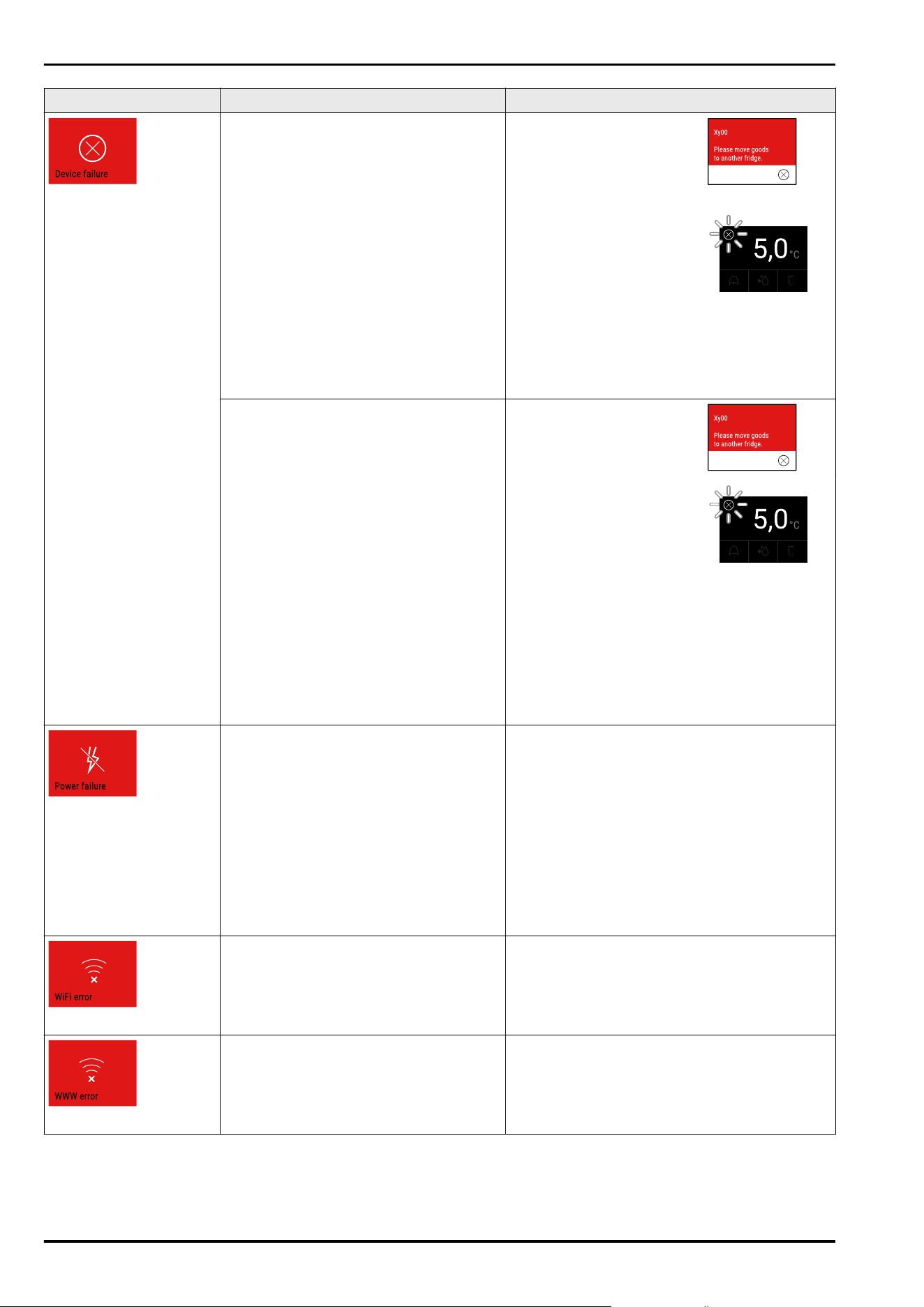
Message (red) Cause Remedy
Error
The appliance is faulty, there is an appli‐
ance error or a component of the appliance
has a fault.
Store the cooled produce
elsewhere.
Tap briefly.
The error code (e.g. BT021) is
displayed.
Tap briefly.
A further error code is
displayed if there is one
or
Status screen is displayed
with flashing error symbol.
Swiping or tapping the display will show the error
code(s) again.
Make a note of error code(s) and contact
Customer Service. (see 10.3 Customer Service)
The message indicates that freeze protec‐
tion mode is active (e.g. due to frequent
door openings or loading with goods).
Tap briefly.
FRZ.PROT is displayed.
Tap briefly.
Status screen is displayed
with flashing error symbol.
Swiping or tapping the display will show the
message again.
The appliance automatically switches to normal
operating mode after a few hours and the
message disappears. Alternatively, the mode and
message can be cancelled with a long tap. If the
message is displayed repeatedly and the causes
listed do not apply, contact customer service.
(see 10.3 Customer Service)
Power cut
The message appears following an inter‐
ruption to the electricity supply.
The operating panel continues running in
battery mode. All functions remain active
except for refrigeration and lighting.
Tap briefly.
Battery’s state of charge, information about
errors and appliance status are displayed
Tap briefly.
The warmest temperature and the period of
power interruptions are displayed.
Tap briefly.
The status screen is displayed.
The current temperature and the alarm symbol
flash red until the set temperature is reached.
Check the quality of the refrigerated goods.
WiFi error
Wi-Fi connection is interrupted. Check connection.
Press briefly.
Alarm is stopped.
WWW error, WiFi
This message appears if there is no
internet connection via WiFi.
Check connection.
Press briefly.
Alarm is stopped.
Controls
* Depending on model and options 45
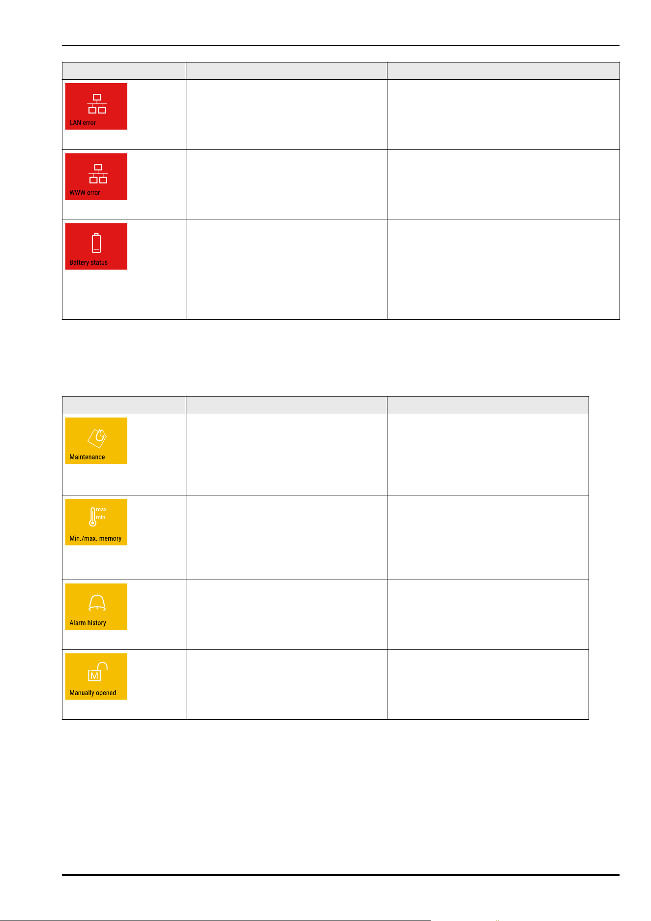
Message (red) Cause Remedy
LAN error
LAN connection is interrupted. Check connection and network cable.
Press briefly.
Alarm is stopped.
WWW error, LAN
This message appears if there is no
internet connection via LAN.
Check connection.
Press briefly.
Alarm is stopped.
Battery error
Low appliance battery level (max. 20%
remaining).
Reconnect the appliance to a power supply
and check whether the battery charge level
has increased after 12 hours. Otherwise contact
Customer Service (see 10.3 Customer Service) or
replace the battery. (see 9.4 Replacing appliance
battery)
Press briefly.
Alarm is stopped.
7.3.2 Reminders
Reminders appear when you are being asked to do some‐
thing. The are issued by means of an acoustic signal and
visually via a symbol on the display. Acknowledge the
message by pressing the confirmation button.
Message (yellow) Cause Remedy
Maintenance reminder
The message appears when the timer for
the set maintenance interval has expired.
Press briefly.
Reminder is closed.
Note
The maintenance interval can be
set (see 7.2.11 Maintenance interval
reminder ) .
Recording reminder
The message appears when the tempera‐
ture recording memory (999 hours) is full.
Press briefly.
Reminder is closed.
The oldest data is overwritten.
Note
The temperature recording can be reset.
(see 7.2.4 Temperature recording )
Alarm log
The message appears if there are more
than 10 unconfirmed alarm messages.
Press briefly.
Check messages.
Reminder is closed.
Manually opened
This message appears if a door which
has been locked electronically is manually
opened.
Close the door.
Press briefly.
Reminder is closed.
8 Features
8.1 Safety lock
The appliance door is fitted with an electronic lock.
Application:
-
Lock and unlock with door code. (see 7.2.6Door lock )
-
Activate and deactivate automatic locking. (see 7.2.6Door
lock )
-
Lock and unlock door with remote control.
(see 7.2.10 Remote control )
-
Door locks automatically after a power failure (cannot be
deactivated).
8.1.1 Emergency unlocking
If there is a power failure, the door can be opened with the
emergency release key.
Features
46 * Depending on model and options
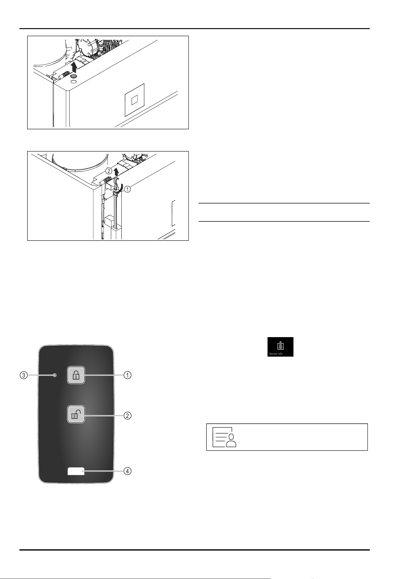
Fig. 247
► Remove cover.
Fig. 248
► Insert the emergency release key Fig. 248 (1) from above,
hook it onto the lock and pull it upwards Fig. 248(2).
▷ The lock is unlocked. You can open the door.
8.2 Remote control
The remote control allows the door lock to be engaged and
unlocked remotely.
It must be linked to the appliance before use.
(see 7.2.10 Remote control )
The battery can be replaced. (see 9.4 Replacing appliance
battery)
Fig. 249
(1)
Engage lock (3) Status LED
(2) Unlock lock (4) Fastening eyelet
8.2.1 Using remote control
► Press button Fig. 249(1) on the remote control.
▷ The lock is engaged. The door cannot be opened.
►
Press button Fig. 249(2) on the remote control.
▷ The lock is unlocked. The door can be opened.
► Status LED Fig. 249 (3) provides a visual acknowledge‐
ment when you press the button.
► Eyelet Fig. 249 (4) for attaching remote control, for
example, to a key ring.
8.3 Sensors
The appliance can be equipped with the following sensors
for temperature monitoring:
-
Safety thermostat sensor
-
C sensor
-
P sensor
8.3.1 Safety thermostat sensor
The safety thermostat sensor monitors the temperature
drop and thus protects against excessively low tempera‐
tures (Freeze Protect). If the temperature drops below the
threshold value, the appliance regulates the temperature
automatically. The error message FRZ. PROT (Freeze Protect)
(see 7.3Message) appears.
Note
Do not cover the safety thermostat sensor.
8.3.2 C sensor (control sensor)
The C sensor is permanently installed and regulates the
interior temperature of the appliance. You can calibrate the
C sensor if necessary. (see 7.2.25 Sensor calibration )
8.3.3 P sensor (reference sensor)
The P sensor is installed securely in the interior and indi‐
cates the product temperature that simulates the temper‐
ature of the refrigerated items. The P sensor temperature
is shown on the status display as the actual tempera‐
ture and the set alarm temperature limit values relate to
this. The P sensor display can be calibrated if required.
(see 7.2.25 Sensor calibration )
8.4 Sensor info
This function makes it possible to choose between C sensor
or P sensor.
Make sure that the following requirement is met:
❑
P sensor is connected to the appliance. (see 8.5 Inter‐
faces)
8.4.1 Selecting C sensor
Fig.250
► Swipe left or right until corresponding function is
displayed.
Features
* Depending on model and options 47
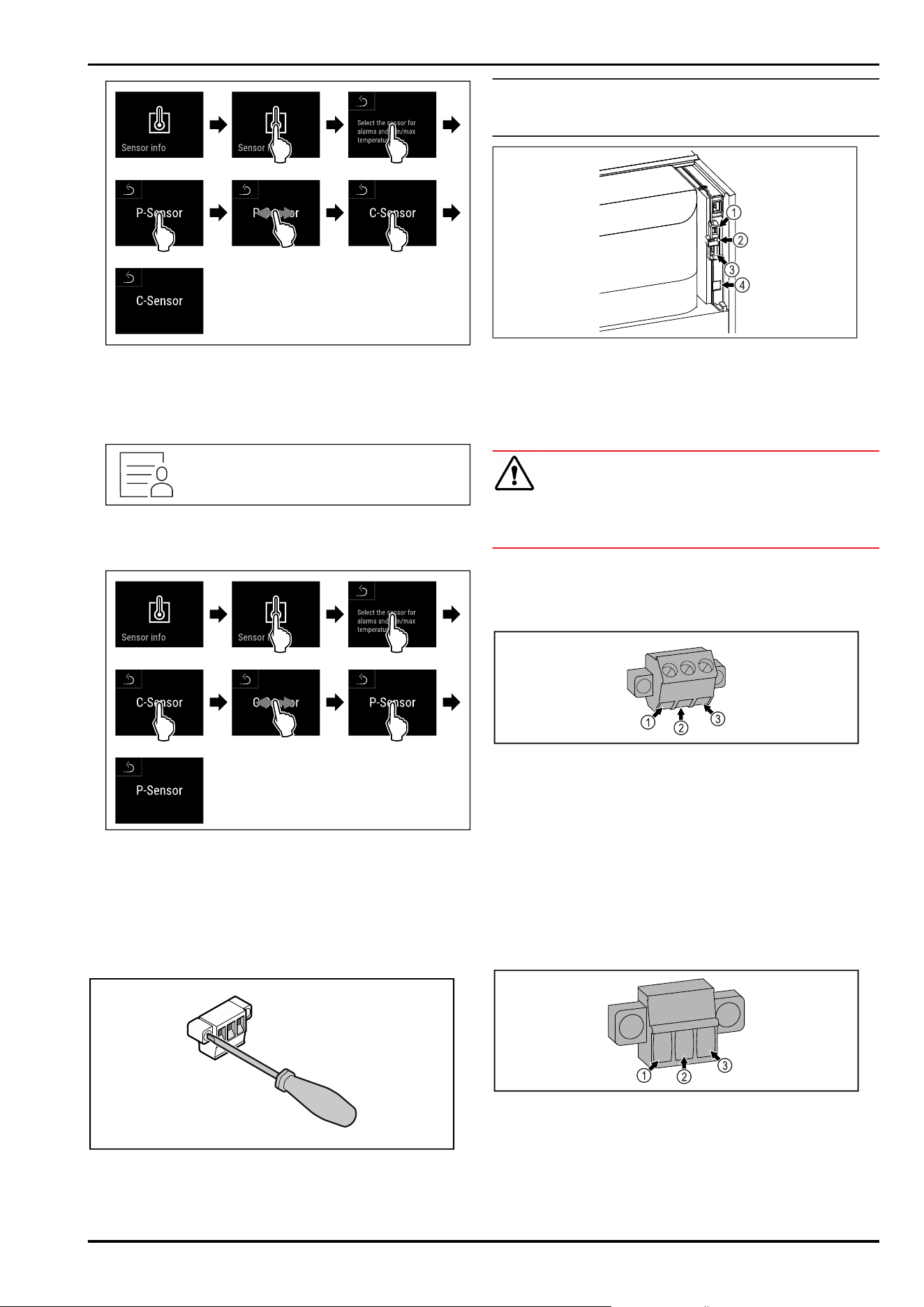
Fig.251
► Carry out action steps according to the illustration.
▷ C sensor has been selected.
8.4.2 Selecting P sensor
Fig.252
► Swipe left or right until corresponding function is
displayed.
Fig.253
► Carry out action steps according to the illustration.
▷ P sensor has been selected.
8.5 Interfaces
There are various connection options on the back of the
appliance.
Fig.254
Note
Screws secure the plugs. To enable disconnection of the
plugs, loosen the screws on the left and right.
Fig.255
(4)
Connection for P
sensor
(3) Potential-free alarm
output
(2) USB interface (4) LAN interface
8.5.1 Potential-free alarm output
WARNING
Risk of injury due to electric shock!
► The appliance may only be connected to an external
alarm device by trained specialist personnel.
These three contacts can be used to connect a visual or
an acoustic alarm device. The connection is designed for
a maximum of 30 V (DC) - 8 A from a safety low voltage
source SELV (minimum current 150mA).
Fig.256
(1)
NO (normally open)
Connection for indi‐
cator lamp, which is
active in normal opera‐
tion or when the appli‐
ance is switched off.
(3) NC (normally closed)
Connection for alarm
lamp or audible alarms,
which is active when
an alarm is triggered or
there is a lack of power
supply.
(2) COM (common)
External voltage
source
8.5.2 Connection for P sensor
Fig.257
(1)
IN+ (measuring line +) (3) FORCE (supply +)
(2) IN- (common return
line -)
Features
48 * Depending on model and options
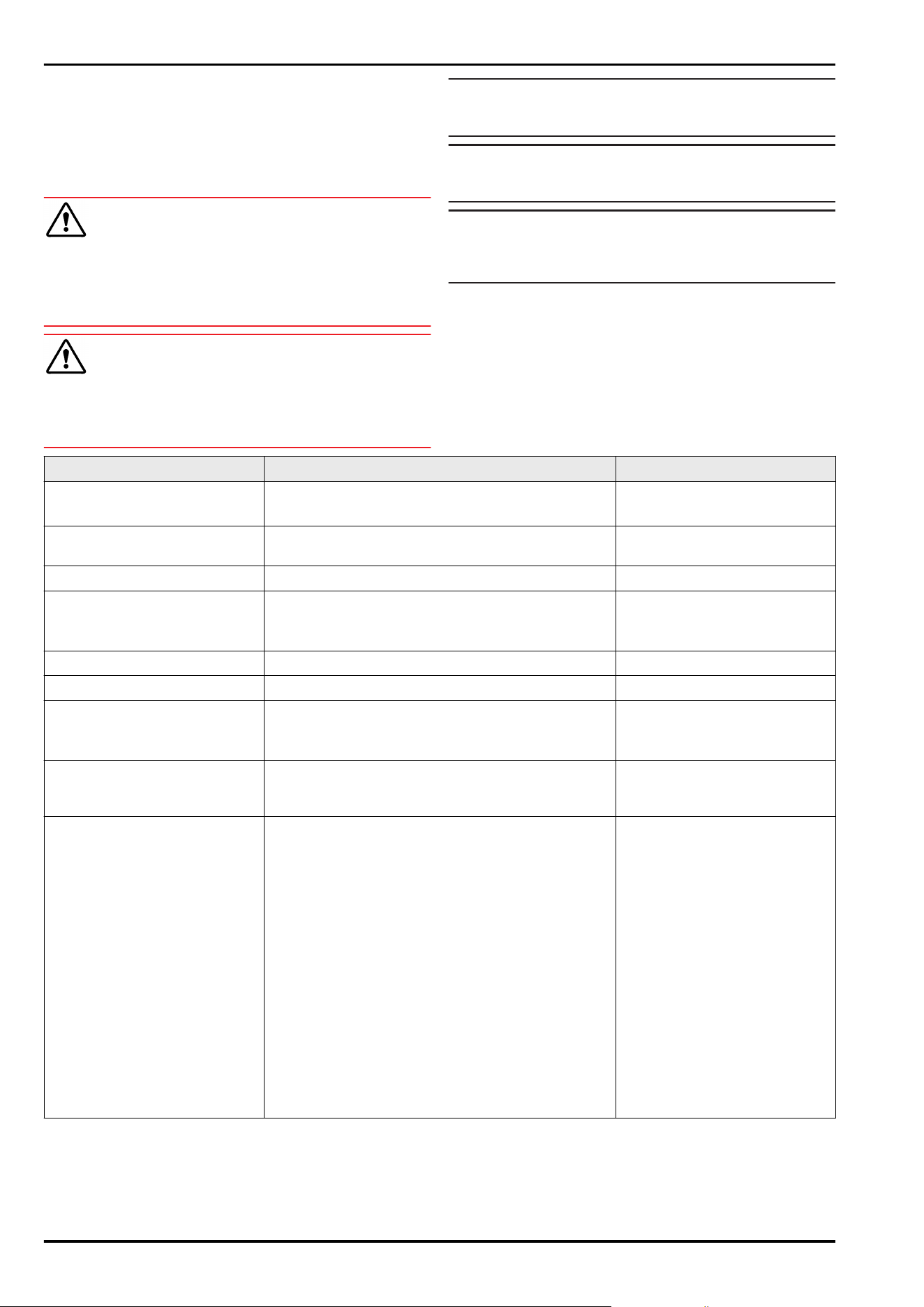
9 Maintenance
9.1 Maintenance schedule
Maintenance work is to be performed at regular intervals to
ensure proper appliance function.
CAUTION
Danger of injury and damage due to unprofessional mainte‐
nance work!
Personal injury and material damage.
► Maintenance work may only be performed by trained
specialist personnel.
WARNING
Short-circuit hazard due to live parts!
Electric shock or damage to the electronics.
► Switch off the appliance.
► Pull out mains plug or switch off fuse.
Note
A maintenance reminder function can be activated.
(see 7.2.11 Maintenance interval reminder )
Note
We recommend creating a maintenance log in which all
work (repairs, checks) performed is documented.
Note
Liebherr recommends yearly maintenance. For an individual
offer, please contact Customer Service (see 10.3 Customer
Service) .
Component Activity Maintenance interval
Sheet metal parts Check for damage and corrosion.
Replace damaged parts: (see 10.3 Customer Service)
Yearly
Door, hinges Check alignment (see 3.6 Aligning the door) , ease of
movement, and tight fit.
Yearly
Lock, door handle * Check for ease of movement and tight fit. Yearly
Door seal Check for damage, wear, and tight fit.
A replacement door seal is available via Customer
Service (see 10.3 Customer Service) .
Yearly
Sensor Calibrate sensor. (see 7.2.25 Sensor calibration ) Yearly
Sensor feedthrough Check that the sealing compound is intact. Yearly
Battery Replace appliance battery.
A replacement battery is available from customer
service. (see 9.4 Replacing appliance battery)
5 to 10 years
Surfaces Cleaning (see 9.3Cleaning the appliance) Recommendation: monthly or
as required/specified at instal‐
lation location
Surfaces Disinfection
Liebherr has tested the following disinfectants:
Dismozon pur 1 % Lösung (Bode Chemie), Suma
Quicksan (Diversey), Incidin Extra N (Ecolab Health‐
care), Acrylan (Antiseptica chem.-pharm. Produkte),
Buraton 10 F (Schülke und Mayr), Frankocid N
(Franken Chemie), Apesin DSR 50 (Tana), Nüscosept
Spray (Dr. Nüsken), Melsept SF (B. Braun Melsungen),
Kohrsolin (Bode Chemie), Neoquat S (Dr. Weigert),
Indicin Rapid (Ecolab Healthcare), Bacillocid Spezial
(Bode Chemie), Neoform K Spray (Dr. Weigert), Apesin
Desinf. Spray (Tana), Nüscosept 100 (Dr. Nüsken),
Antisept T (Fink Tec), Apesin AP 100 0,50% Lösung
(Tana), Perform Pulver 2% Lösung (Schülke und Mayr)
Observe the operating instructions of the respec‐
tive manufacturer. If disinfectants other than those
stated are used, test them on a less exposed area
first.
Recommendation: monthly or
as required/specified at instal‐
lation location
Maintenance
* Depending on model and options 49
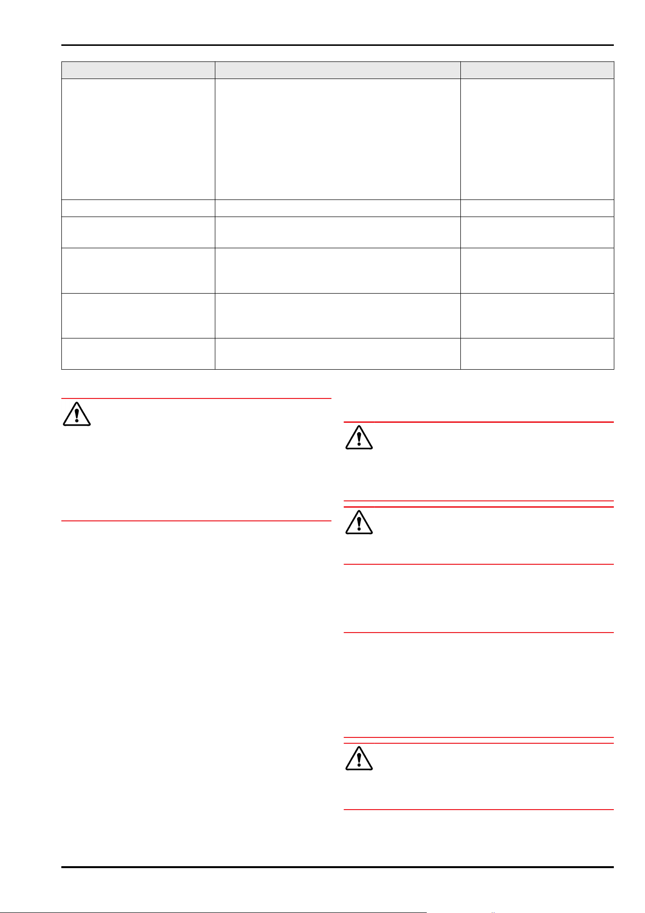
Component Activity Maintenance interval
Installation location, appliance Decontamination
The appliance is suitable for room decontamination
with hydrogen peroxide H
2
O
2
.
In this context, the values of the following applica‐
tion specifications must not be exceeded:
Concentration: maximum 250 ppm.
Humidity: maximum 85%.
Maximum permissible room temperature as per
climate class. (see2.4 Range of use of appliance)
Recommendation: as required/
specified at installation location,
maximum 2x per year
Fan air slots Cleaning Yearly
Alarm relay
Sensor
Check plug connections for tight fit. Yearly
Mains cable Check for damage. Yearly
or
if there is a change of location
Tilt angle Check for proper function and tight fit. Yearly
or
if there is a change of location
Adjusting feet/castors Check for proper function, damage, and tight fit.
Replace damaged parts. (see 10.3 Customer Service)
Yearly
9.2 Defrosting appliance
WARNING
Improper defrosting of the appliance!
Injuries and damage.
► Do not use mechanical equipment or other methods to
speed up the defrosting process other than those recom‐
mended by the manufacturer.
► Do not use electrical heating or steam-cleaning appli‐
ances, naked flames or defroster sprays to defrost.
► Do not use sharp objects to remove ice.
Defrosting is performed automatically. The defrost water
drains through the opening and evaporates.
To maintain the functionality of the appliance, we recom‐
mend defrosting it when there is a high buildup of ice.
Icing in the interior is determined by the location (e.g.
high humidity), settings on the appliance and incorrect user
behaviour.
If the automatic defrosting cycle is insufficient:
► Start automatic defrosting manually.
(see 7.2.23 Defrosting )
If the problem persists, defrost the appliance manually:
► Switch off appliance. (see 7.2.2 Switching appliance on
and off )
► Pull out mains plug.
► Store refrigerated items elsewhere.
► Leave appliance door open during defrosting process.
► Soak up remaining defrost water with a cloth, clean drain
opening and the appliance.
9.3 Cleaning the appliance
9.3.1 Preparing
WARNING
Short-circuit hazard due to live parts!
Electric shock or damage to the electronics.
► Switch off the appliance.
► Pull out mains plug or switch off fuse.
WARNING
Risk of fire
► Do not damage the refrigeration circuit.
►
Empty the appliance.
► Pull out the mains plug.
► Observe the notes on transporting the appliance.
9.3.2 Cleaning housing
NOTICE
Improper cleaning!
Damage to the appliance.
► Only use soft cleaning cloths and ph-neutral all-purpose
cleaners.
► Do not uses abrasive sponges or steel wool which may
cause scratches.
► Do not use any sharp or abrasive cleaning agents, nor
any that contain sand, chloride or acid.
WARNING
Risk of injury and damage as a result of hot steam!
Hot steam can lead to burns and can damage the surfaces.
► Do not use any steam cleaners!
Maintenance
50 * Depending on model and options
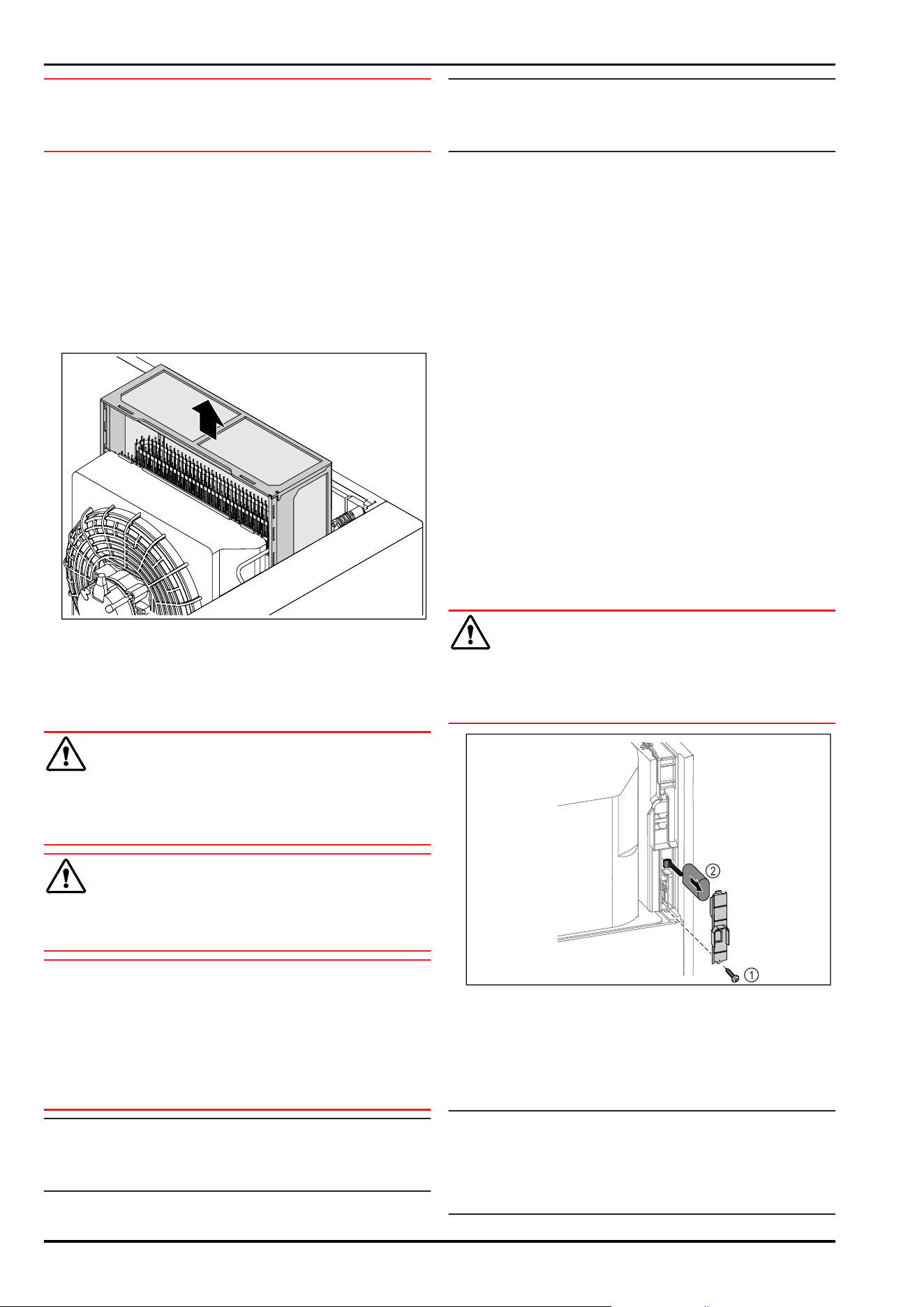
NOTICE
Risk of damage due to short circuit.
► When cleaning the appliance, make sure no water gets
into the electrical components.
► Wipe the housing down with soft, clean cloth. If very
dirty, use lukewarm water with a neutral cleaner. Glass
surfaces can also be cleaned with glass cleaner.
► Clean condenser coil each year. If the condenser coil is
not cleaned, this significantly reduces the efficiency of
the appliance.
9.3.3 Cleaning the dust filter
The dust filter is located on the top of the appliance. Clean
the dust filter at least twice a year.
► Remove mains plug.
Fig.258
► Pull the dust filter out upwards.
► Clean the dust filter with water and rinsing liquid.
► Insert the dust filter.
9.3.4 Cleaning interior
WARNING
Short-circuit hazard due to live parts!
Electric shock or damage to the electronics.
► Switch off the appliance.
► Pull out mains plug or switch off fuse.
WARNING
Risk of injury and damage as a result of hot steam!
Hot steam can lead to burns and can damage the surfaces.
► Do not use any steam cleaners!
NOTICE
Improper cleaning!
Damage to the appliance.
► Only use soft cleaning cloths and ph-neutral all-purpose
cleaners.
► Do not uses abrasive sponges or steel wool which may
cause scratches.
► Do not use any sharp or abrasive cleaning agents, nor
any that contain sand, chloride or acid.
Note
► Defrost water drain (see 2.2 Overview of appliances and
equipment) : Remove deposits using a thin material (for
example a cotton bud).
Note
Do not damage or remove the type plate on the inside of the
appliance. The type plate is important for Customer Service.
(see 10.3 Customer Service)
► Open the door.
► Empty the appliance.
► Clean interior and equipment parts with lukewarm water
and a little detergent. Do not use any gritty or acidic
cleaning agent or any chemical solvent.
9.3.5 After cleaning
► Wipe appliance and equipment parts dry.
► Connect and switch on appliance.
Once the temperature is sufficiently cold:
► put in items for refrigeration goods.
► Repeat cleaning regularly.
► Clean and remove dust from the refrigeration unit with
heat exchanger once a year.
9.4 Replacing appliance battery
In the event of a power failure, the appliance battery is used
to record temperature history, alarm and service messages
and to show the alarm messages on the display for approx‐
imately 12 hours. During initial commissioning, the battery
may take up to 24 hours to charge and be in proper working
order.
A replacement battery is available from customer service
(see 10.3 Customer Service) .
9.4.1 Replacing battery
WARNING
Short-circuit hazard due to live parts!
Electric shock or damage to the electronics.
► Switch off the appliance.
► Pull out mains plug or switch off fuse.
Fig. 259
► Unscrew screw and remove cover from the back of the
appliance Fig. 259(1).
► Disconnect and remove battery Fig. 259(2).
► Install replacement battery.
► Close the cover and screw in the screw.
► Reconnect mains power cable.
Note
► The battery must be sent for separate waste treatment
for batteries and must be disposed of in an expert and
proper manner in accordance with the regulations and
laws which apply locally. Do not damage or short circuit
the battery!
Maintenance
* Depending on model and options 51
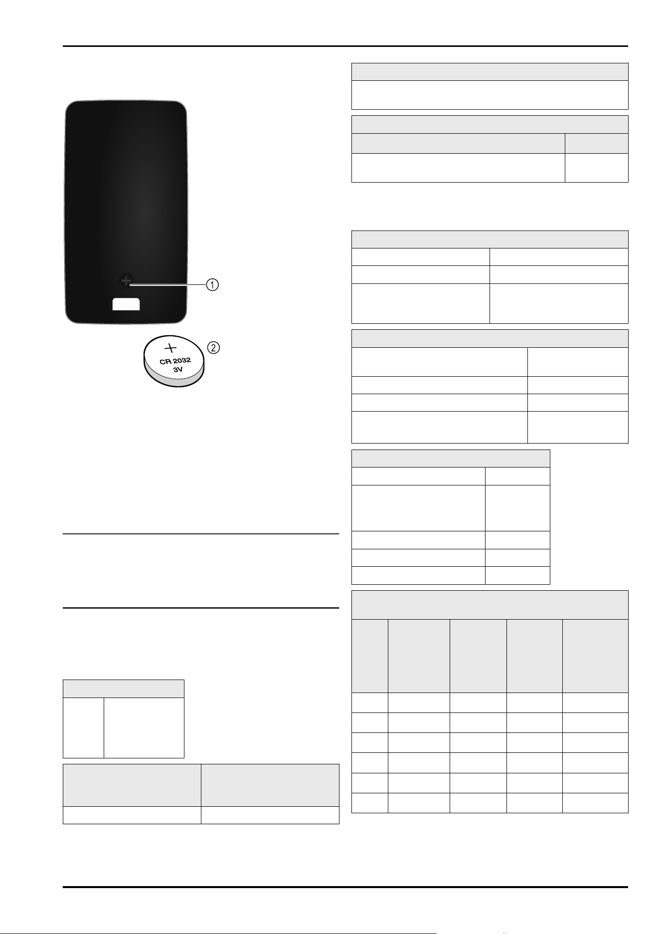
9.5 Replacing the remote control
batteries
Fig. 260
The remote control is powered by a 3V CR 2032 battery
Fig. 260(2)available from specialist retailers.
9.5.1 Replacing battery
► Undo screw Fig. 260(1) on the back of the remote control.
► Remove rear.
▷ Battery compartment is open.
► Replace battery.
► Close battery compartment.
► Screw back together.
Note
► The battery must be sent for separate waste treatment
for batteries and must be disposed of in an expert and
proper manner in accordance with the regulations and
laws which apply locally. Do not damage or short circuit
the battery!
10 Customer help
10.1 Technical specifications
Temperature range
Cooling Foamed door:*
-2°C to +16°C*
Glass door:*
0°C to +16°C*
Maximum load of grid
shelves
A)
Maximum load of centre
grid shelf
A)
(see 5.2 Using
equipment)
60 kg 10 kg
A)
Heavier loads may result in a slight bending of the
shelves.
Net capacity
See net capacity on the type plate. (see 2.2 Overview of
appliances and equipment)
Lighting
Energy efficiency class
A)
Light source
This product contains one or more energy
efficiency class G light sources
LED
A)
The appliance may contain light sources with different
energy efficiency classes. The lowest energy efficiency
class is indicated.
WLAN frequency specification
Frequency band 2.4GHz
Maximum radiated power <100 mW
Purpose of the wireless
equipment
Integration in the local WiFi
network for data communi‐
cation
Set-up conditions
Degrees of pollution (surrounding
the appliance)
PD2
Ambient temperature +10°C to +35°C
Maximum relative ambient moisture 75%, not condensing
Maximum operating elevation
(metres above sea level)
2000m
1500m(glass door)
Electrical values
Nominal voltage 220-240 V~
Frequency 50Hz*
(SRPvh 1412)
50/60Hz*
Connected load 4,0A
Maximum mains fluctuation +/-10%
Overvoltage categories II
Data as per DIN 13277 measured at a reference ambient
temperature of +25°C
Model
SRPvh
Energy
consump‐
tion (kWh/
24h)
Tempera‐
ture rise
during
mains
failure
(min)
Tempera‐
ture
homoge‐
neity (°K)
Temperature
constancy
(°K)
1402 1.227
126
A)
0.7
B)
1.1
B)
1412 1.944
90
A)
1.0
B)
1.0
B)
6501 0.487
101
A)
1.0
B)
1.7
B)
6511 0.850
89
A)
1.2
B)
2.1
B)
8401 0.596
125
A)
0.7
B)
1.4
B)
8411 1.006
96
A)
1.0
B)
1.5
B)
A)
Heating reference body: from +5 °C to +10 °C / reference
body: 50 ml glass container filled with 25 ml isopropanol
and 25ml water
B)
Measured at reference setpoint temperature of +5°C
Customer help
52 * Depending on model and options
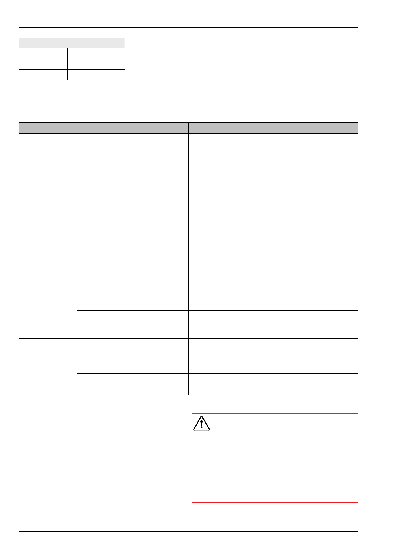
Appliance battery
Type 1S2P/NCR 18650BF
Nominal voltage 3.6 VDC
Capacity 6.7Ah
10.2 Technical fault
Your appliance is designed and built to ensure it works reli‐
ably and has a long service life. In the unlikely event that
a fault occurs during operation, please check whether the
fault is due to an operating error. If this is the case, you will
be charged for the cost incurred even if this falls within the
warranty period.
You can fix the following faults yourself.
10.2.1 Appliance function
Defect Cause Remedy
The appliance is
not working.
→ The appliance is not switched on. ► Switch on the appliance.
→ The mains plug is not properly
plugged into the socket.
► Check the mains plug.
→ There is something wrong with the
fuse in the socket.
► Check fuse.
→ Power cut ► Keep the appliance closed.
► The door can be opened using the emergency release
key. (see8.1 Safety lock)
► If necessary move the refrigerated/frozen items to
another fridge or freezer if the power is off for a
prolonged period.
→ The IEC socket is not plugged into
the appliance correctly.
► Check the IEC socket.
Temperature is not
cold enough.
→ The appliance door is not closed
properly.
► Close appliance door.
→ Ventilation is not sufficient. ► Clear ventilation grille and clean it.
→ The ambient temperature is too
high.
► Ensure the correct ambient conditions: (see2.4 Range of
use of appliance)
→ The appliance was opened too
many times or for too long.
► Wait to see if the appliance goes back to the required
temperature by itself. If not, contact Customer Service.
(see 10.3 Customer Service)
→ The temperature is set incorrectly. ► Set a colder temperature and check after 24 hours.
→ The appliance is too close to a heat
source (oven, radiator, etc).
► Change where the appliance or the heat source are
located.
Remote control is
not working.
→ The remote control battery is
empty.
► Replace battery.
→ The radio connection with the
appliance is too weak.
► Reduce the distance to the appliance.
→ Remote control not paired. ► Pair remote control again: (see 7.2.10 Remote control )
→ Remote control is faulty. ► Contact Customer Service. (see 10.3 Customer Service)
10.3 Customer Service
First check whether you can remedy the fault yourself . If
this is not the case, please contact Customer Service.
You can find the address in the enclosed brochure “Liebherr-
Service” or at home.liebherr.com/service.
WARNING
Unprofessional repair!
Injuries.
► Have any repairs and action - not expressly specified -
on the appliance and mains cable carried out by service
personnel only. (see9 Maintenance)
► A damaged mains cable may only be replaced by the
manufacturer, the manufacturer’s Customer Service or a
similarly qualified person.
► In the case of appliances with an IEC connector, the
change may be made by the customer.
Customer help
* Depending on model and options 53
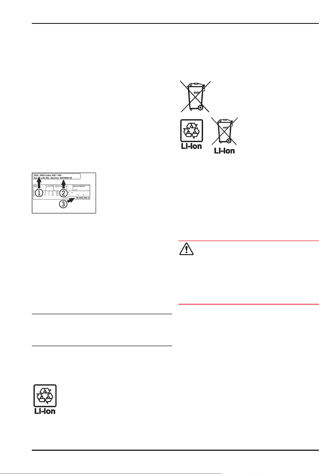
10.3.1 Contacting Customer Service
Make sure you have the following appliance data at the
ready:
❑
Appliance name (model and index)
❑
Service no. (Service)
❑
Serial no. (S no.)
► Access the appliance information via the display
(see 7.2.20 Device information ) .
-or-
► Refer to the type plate for appliance information.
(see 10.4 Type plate)
► Note down appliance information.
► Inform Customer Service: Report faults and the appliance
information.
▷ This will help us to provide a fast and focussed service.
► Follow any further instructions provided by Customer
Service.
10.4 Type plate
The type plate is inside the appliance. See appliance over‐
view.
Fig. 261
(1)
Appliance designation (3) Serial No.
(2) Service No.
11 Shutting down
► Empty the appliance.
► Switch off the appliance.
► Pull the mains plug out of the socket.
► Remove the IEC socket if required: Pull the IEC socket out
of the appliance plug and move it to the left and right at
the same time.
► Clean appliance (see 9.3Cleaning the appliance) .
► If present: Remove the covers and insulation from the
sensor feed-through to prevent mould forming.
► Leave the door open so that no bad odours form.
Note
Damage to the appliance and malfunctions!
► After shutting down, only store the appliance at the
permitted room temperature of between -10 °C and
+50°C.
12 Disposal
12.1 Preparing appliance for disposal
Liebherr uses batteries in some of its appli‐
ances. In the EU, for environmental reasons,
legislation obliges the end user to remove
these batteries before disposing of old appli‐
ances. If your appliance contains batteries, a
corresponding notice is attached.
Lamps If you can remove the lamps yourself without
destroying them, also remove these before
disposal.
► Take the appliance out of operation.
► Appliances with batteries: remove the batteries. For
description, see Maintenance chapter.
► If possible: remove lamps without destroying them.
12.2 Disposing of the appliance in an
environmentally friendly manner
The appliance still contains
valuable materials and must
be disposed of separately from
unsorted municipal waste.
Dispose of batteries separately
from the old appliance. To do
this, you can return the batteries
free of charge to retailers as
well as recycling centres and
collection centres for recyclable
materials.
Lamps Dispose of removed lamps
via the respective collection
systems.
For Germany: You can dispose of the appli‐
ance free of charge via the
class 1 collection containers
at the local recycling and
recyclable material collection
centres. When purchasing a new
fridge/freezer, if the sales area
> 400 m
2
, retailers will also take
back the old appliance free of
charge.
WARNING
Leaking coolant and oil!
Fire. The coolant contained in the appliance is eco-friendly,
but also flammable. The oil contained in the appliance
is flammable. Escaping coolant and oil can ignite if the
concentration is high enough and in contact with an
external heat source.
► Do not damage the pipelines of the coolant circuit and
the compressor.
► Observe the notes on transporting the appliance.
► Transport the appliance without damaging it.
► Dispose of batteries, lamps and the appliance according
to the above specifications.
13 Additional information
Further information on warranty conditions can be found in
the enclosed service brochure or on the Internet at https://
home.liebherr.com.
Shutting down
54 * Depending on model and options
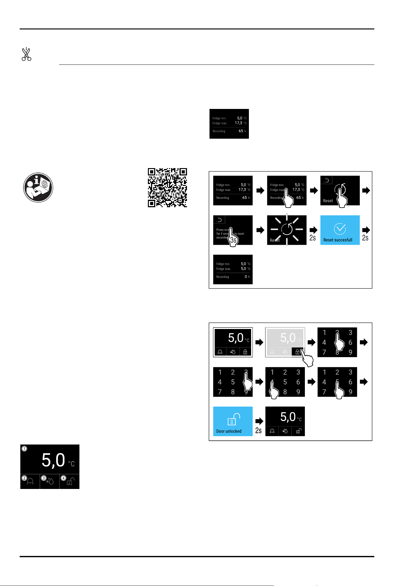
Pass on this info in
the event of a device
fault:
Model identifier /
Inventory number:
Quick Start Guide for everyday use
Information about using this Quick Start Guide:
-
This Quick Start Guide is not a substitute for the full
operating instructions nor is it a substitute for appliance
training.
-
This Quick Start Guide provides support for everyday use
and handling the appliance.
-
Read the full operating instructions and the safety notes
contained therein.
This quick start guide is for: SRPvh 14../65../84..
Scanning the QR code will
open the full operating
instructions:
Intended use
This laboratory refrigerator is suitable for the professional
storage of products at temperatures between:
-
Foamed door: -2°C and 16°C.*
-
Glass door: 0°C and 16°C.*
Foreseeable incorrect use
Do not use the appliance for the following applications:
-
Storage and refrigeration of:
•
Chemically unstable, flammable or corrosive
substances
•
Blood, plasma or other body fluids for the purpose of
infusion, application or introduction in the human body
-
Use in potentially explosive atmospheres
-
Use outdoors or in areas exposed to dampness and
splashing water
When stocking, observe the following points:
❑
Position grid shelves according to the height required.
❑
Observe maximum load.
❑
When the storage temperature has been reached, load
the appliance (compliance with cold chain).
❑
Produce for cooling must not come into contact with the
evaporator on the rear wall.
❑
Keep liquids in closed containers.
❑
Leave space when storing refrigerated goods to ensure
good air circulation.
Status display
Fig. 262
(1)
Actual temperature (3) Defrosting status
(2) Alarm status (4) Door lock status
Displaying temperature recording
The temperature recording displays the length of the
recording and the minimum and maximum temperatures
measured during this period of time.
Fig. 263
Resetting temperature recording
Fig. 264
Unlocking door lock with door PIN
Fig. 265 Example shows PIN 2345
Quick Start Guide for everyday use
* Depending on model and options 55
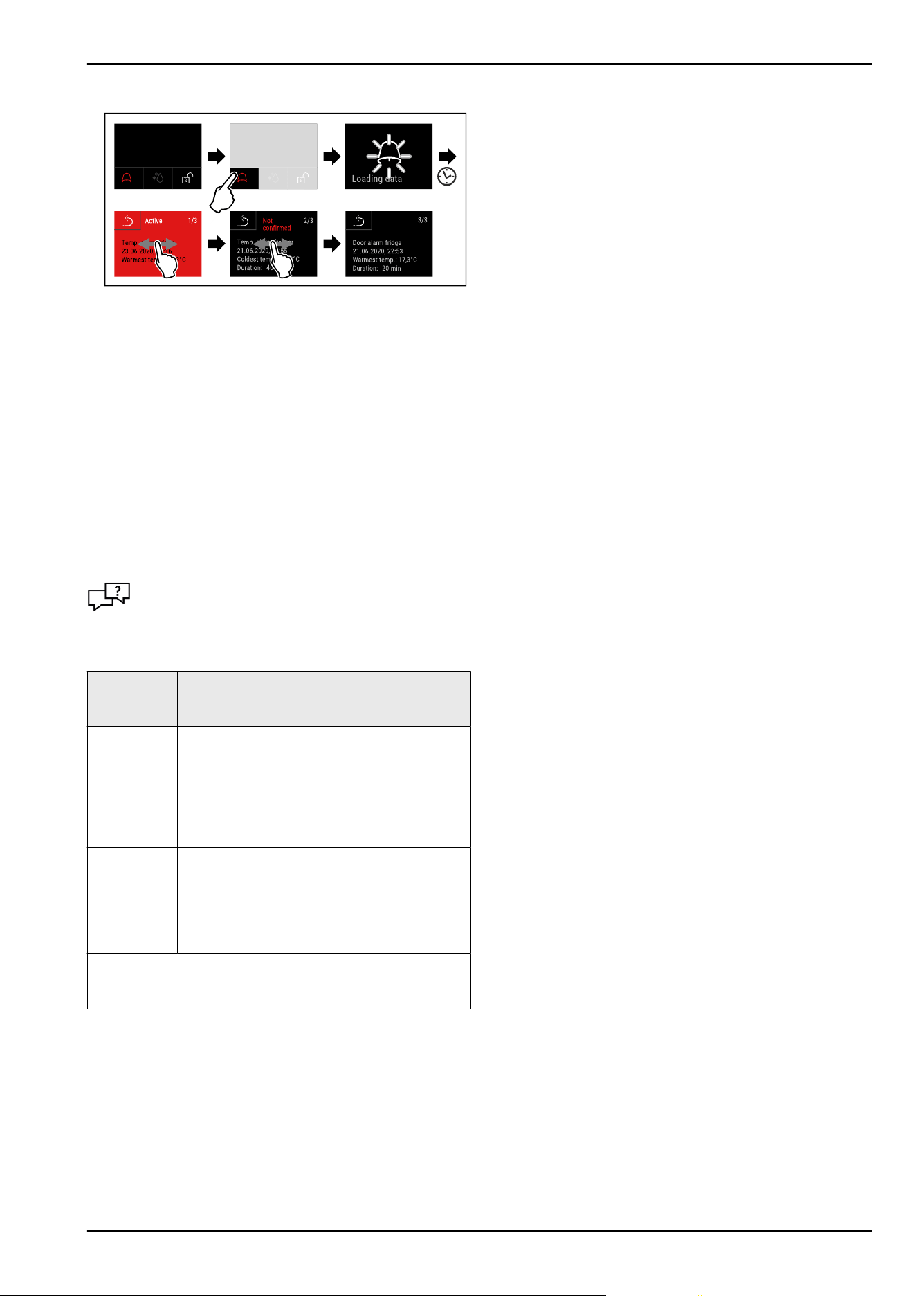
Displaying alarm log
Fig. 268 Example shows an active alarm, an unconfirmed
alarm, and a confirmed alarm.
▷ Alarm log shows active, confirmed or unconfirmed alarms
(maximum 10 alarms).
▷ To delete the alarm log: See operating instructions.
Cleaning appliance
► Empty the appliance.
► Pull out the mains plug.
► Observe the information in the operating instructions.
► Dry the appliance and equipment thoroughly after
cleaning.
► Connect the appliance.
► Switch on the appliance.
► Load the appliance once the storage temperature is
reached.
What should I do if there is a fault?
A message appears in the display if there is a fault.
Messages have different meanings:
Symbol
colour in the
display
Meaning Remedy
YELLOW
Reminder
Reminder of general
procedures. You can
carry out these
procedures to
eliminate the
message.
Consult the operating
instructions and
perform the
troubleshooting
steps.
RED
Warning
Appears when there
are malfunctions.
You can eliminate
simple malfunctions
yourself.
Consult the operating
instructions and
perform the
troubleshooting
steps.
If you cannot remedy the fault yourself, contact a
competent member of staff or your nearest customer
service outlet.
Quick Start Guide for everyday use
56 * Depending on model and options
home.liebherr.com/fridge-manuals
Refrigerator
ORIGINAL OPERATOR'S MANUAL
Issue date:20251205
Part number index:7083324-00
Liebherr Hausgeräte Lienz GmbH
Dr.-Hans-Liebherr-Strasse 1
A-9900Lienz
Österreich