User Guide
Quality, Design and Innovation
home.liebherr.com/fridge-manuals

Contents
1 The appliance at a glance............................. 3
1.1 Included in delivery............................................. 3
1.2 Overview of appliance and equipment............ 3
1.3 Special features.................................................. 4
1.4 Range of appliance use...................................... 4
1.5 Sound emission of the appliance..................... 5
1.6 Conformity............................................................ 5
2 General safety instructions.......................... 5
3 Functionality of the Touch display............... 7
3.1 Navigation and symbol explanation................ 7
3.2 Menus.................................................................... 8
3.3 Sleep mode.......................................................... 8
4 Start-up......................................................... 8
4.1 Setup conditions................................................. 8
4.2 Appliance dimensions........................................ 9
4.3 Transporting the appliance............................... 9
4.4 Unpacking the appliance................................... 10
4.5 Removing the transport lock............................. 10
4.6 Installing the door handle................................. 10
4.7 Mounting the anti-tipping device..................... 10
4.8 Setting up the appliance................................... 11
4.9 Leveling out the appliance................................ 11
4.10 Setting up multiple appliances......................... 12
4.11 After setup........................................................... 12
4.12 Disposal of packaging........................................ 12
4.13 Reversing the door opening direction............. 12
4.14 Aligning the door................................................. 20
4.15 Connecting the appliance to the power
supply.................................................................... 21
4.16 Switching on the appliance (first use)............ 22
5 Storage.......................................................... 22
5.1 Information regarding storing items................ 22
6 Use................................................................. 22
6.1 Control and display elements........................... 22
6.1.1 Status display.................................................. 23
6.1.2 Display symbols...............................................23
6.1.3 Acoustic signals...............................................23
6.2 Appliance functions............................................ 24
6.2.1 Notes on the appliance functions................ 24
6.2.2 Switching appliance on and off ................... 24
6.2.3 Temperature .................................................... 24
6.2.4 Temperature recording .................................. 25
6.2.5 Settings menu access protection ................25
6.2.6 Access codes....................................................26
6.2.7 Maintenance interval reminder .....................27
6.2.8 Language ......................................................... 28
6.2.9 Temperature unit............................................ 28
6.2.10 Display Brightness ........................................ 28
6.2.11 Alarm Sound..................................................... 28
6.2.12 Key Sound......................................................... 29
6.2.13 WiFi connection .............................................. 29
6.2.14 LAN connection ...............................................30
6.2.15 Appliance information ...................................31
6.2.16 Operating hours .............................................. 32
6.2.17 Software ..........................................................32
6.2.18 Defrosting ........................................................ 32
6.2.19 Sensor calibration .......................................... 33
6.2.20 Temperature alarm ......................................... 33
6.2.21 Door alarm ...................................................... 35
6.2.22 Alarm simulation .............................................36
6.2.23 Alarm forwarding ............................................36
6.2.24 Demo mode...................................................... 37
6.2.25 Resetting to factory settings ...................... 38
6.3 Messages.............................................................. 38
6.3.1 Warnings...........................................................38
6.3.2 Reminders.........................................................40
7 Equipment...................................................... 40
7.1 Safety lock........................................................... 40
7.2 Sensors................................................................. 41
7.3 Interfaces............................................................. 41
8 Maintenance.................................................. 42
8.1 Maintenance schedule....................................... 42
8.2 Defrosting the appliance................................... 44
8.3 Cleaning the appliance...................................... 44
9 Customer support......................................... 45
9.1 Technical data..................................................... 45
9.2 Technical malfunction........................................ 46
9.3 Customer Service................................................ 46
9.4 Type plate............................................................. 47
10 Shutting down............................................... 47
11 Disposal......................................................... 47
11.1 Preparing the appliance for disposal............... 47
11.2 Disposing of the appliance in an
environmentally friendly manner..................... 47
12 Additional information.................................. 48
13 Quick Start Guide for everyday use.............. 49
Congratulations on the purchase of your new appli‐
ance. With this purchase, you have chosen all the
advantages of the latest refrigeration technology, guar‐
anteeing you a high-quality appliance with a long life
span and high operating safety.
The equipment of your appliance gives you the highest
level of day-to-day ease of operation.
Together we are making an active contribution to the
conservation of our environment by purchasing this
appliance which is manufactured in an environmentally
friendly process with the use of recyclable materials.
We hope you enjoy your new appliance.
The manufacturer is constantly working to improve all
types and models. Therefore, please be aware that we
reserve the right to make changes to the shape, equip‐
ment and technology.
Symbol
Explanation
Read instructions
Please read the information in these
instructions carefully to understand all of
the benefits of your new appliance.
2 * Depending on model and options
Symbol Explanation
Additional information online
The digital manual with supplemental
information can be found online by scan‐
ning the QR code on the front page of this
manual or by entering the service number
at home.liebherr.com/fridge-manuals.
Check appliance
Check all parts for transport damage. If you
have any complaints, please contact your
agent or customer service.
Differences
These instructions apply to a range of
models, so there may be differences.
Sections that apply to certain models only
are indicated by an asterisk (*).
Instructions and results
Instructions are marked with a
.
Results are marked with a
.
Videos
Videos about the appliances are available
on the YouTube channel of Liebherr-Hausg‐
eräte.
Open-source licenses:
The appliance includes software components that
make use of open-source licenses. You can find
information on the open-source licenses to be used
here: home.liebherr.com/open-source-licenses
These operating instructions apply to:
-
SRFfg 3501
-
SRFfg 5501
1 The appliance at a glance
1.1 Included in delivery
Check all parts for transport damage. If you have any
issues, please contact your dealer or Customer Service.
(see 9.3 Customer Service)
The delivery contains the following parts:
-
Freestanding appliance
-
Equipment *
-
Installation materials *
-
Operating instructions
-
Warranty documents
-
Quality certificate *
-
Power cable
-
Wall fastening kit
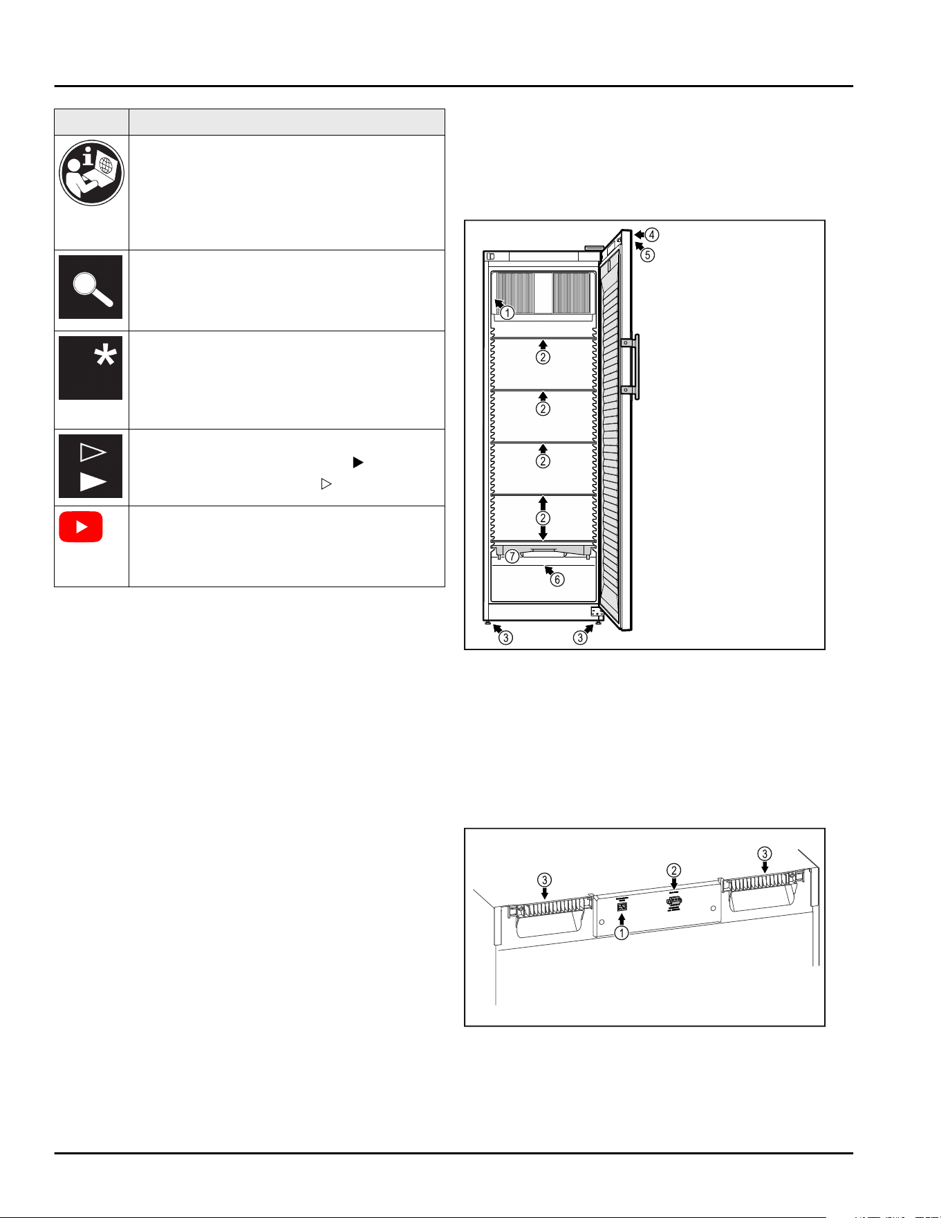
1.2 Overview of appliance and equip‐
ment
SRFfg 3501
SRFfg 5501
Fig. 1 Example illustration
Equipment
(1)
Type plate (5) Control elements and
temperature display
(2) Glass shelf (6) Safety thermostat
sensor
(3) Adjustable feet (7) Defrost water collec‐
tion tray
(4) Lock
Fig. 2 Example illustration of the rear
Equipment
(1)
LAN/WiFi interface * (3) Carrying aid
(2) Potential-free alarm
output
The appliance at a glance
* Depending on model and options 3
1.3 Special features
Note
Accessories are available from the Liebherr Service
Center. The address for your respective country can be
found on the back of the instructions.
SmartModule
The appliance can be equipped with a SmartModule.
This is a WiFi and LAN interface for the connection
between the appliance and an external documenta‐
tion and alarm system such as Liebherr SmartMoni‐
toring.
Liebherr SmartMonitoring Dashboard is not available
in all countries. Check for availability via the QR code
(see6.2.13WiFi connection ) and entering your model.
Retrofitting drawers
Temperature qualification is required when retrofit‐
ting drawer systems in Liebherr refrigerators/freezers
where these are used for temperature-sensitive mate‐
rials such as chilled drugs and refrigerated products
which are subject to specific standards requirements.
Retrofitting drawers in Liebherr refrigerators/freezers
can result in the goods stored becoming spoiled or
damaged. The retrofitting must therefore be
completed exclusively by authorized service providers
from the manufacturer of the refrigerator/freezer.
1.4 Range of appliance use
Intended use
This laboratory refrigerator, with an interior
free of ignition sources, is suitable for profes‐
sional storage of highly flammable products in
closed containers, at temperatures between
3°C(38°F) and 16°C(60°F).
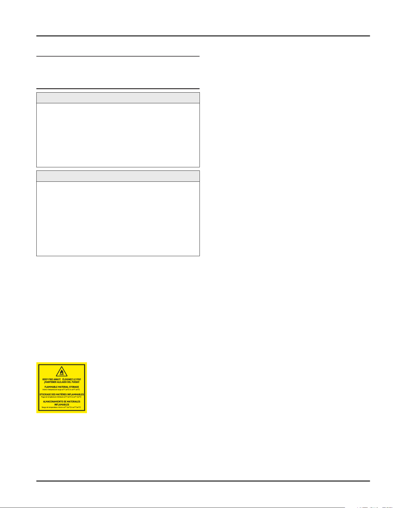
Explosion-proof interior
The values relating to your appliance are
printed on the sticker on the appliance door.
Fig.3
The interior, which is free from sources of igni‐
tion, is used for storing flammable substances
in closed containers and meets the require‐
ments for Class I, Division 2 for storage of
flammable materials equivalent of Gas Group
B. Complies with the applicable requirements
of NFPA 45 and NFPA 99. This is not an explo‐
sionproof refrigerator.
Observe the following specifications for
storage:
-
Pay attention to the corresponding zones,
explosion groups and temperature classes
for the substances to be stored.
-
Observe the spontaneous combustion
temperature. The spontaneous combustion
temperature of the substances to be stored
must be higher than temperature class T6 (>
85°C(185°F)).
-
Refer to the corresponding safety data
sheet for the storage conditions of the prod‐
ucts to be stored.
-
Observe the maximum storage quantities.
-
Observe the applicable directives if you
want to store different substances together.
-
If unsure, contact a safety expert or the
supplier if the relative material is suitable
for storage.
-
Observe local and specific directives and
requirements to ensure the safety of
personnel and the facility.
Storage of temperature-sensitive substances
requires the use of an independent, perma‐
nently monitored alarm system. This alarm
system must be designed such that a respon‐
sible person can record every alarm condition
to be able to take suitable measures.
Foreseeable incorrect use
Do not use the appliance for the following
applications:
-
Storage and cooling of:
•
Chemically unstable substances
•
Blood, plasma or other body fluids for the
purpose of infusion, application or intro‐
duction in the human body.
-
Use in potentially explosive atmospheres.
-
Use outdoors or in areas exposed to damp‐
ness and splashing water.
Any misuse of the appliance may result in
damage to or spoilage of stored goods.
Climate classes
The climate class for your appliance is printed
on the identification plate.
The appliance at a glance
4 * Depending on model and options
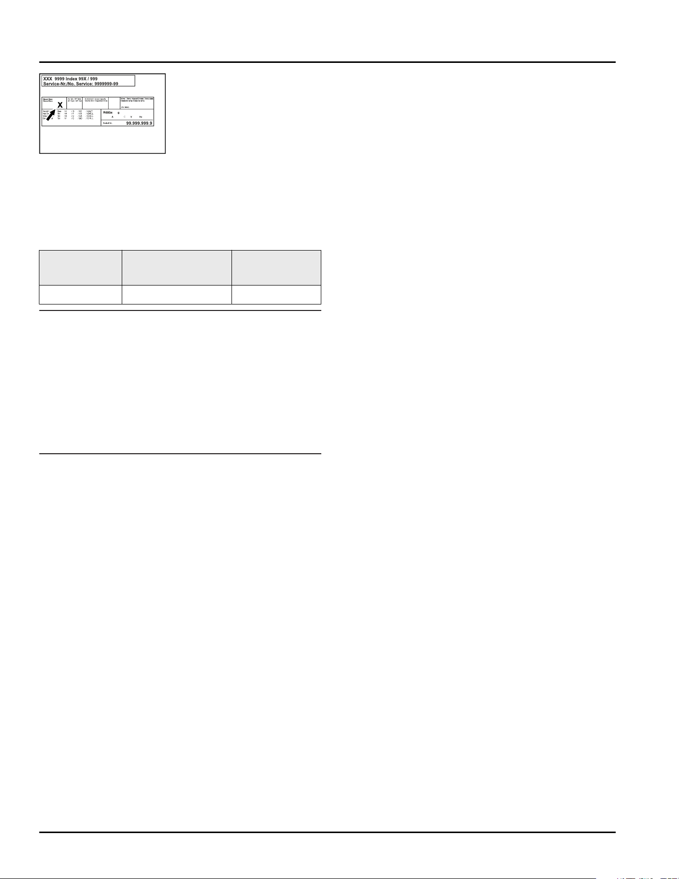
Fig. 4 Type plate
(X) This climate class
indicates the envi‐
ronmental condi‐
tions in which the
appliance can be
operated safely.
Climate
class (X)
max. room
temperature
max. rel.
humidity
7 35°C(95°F) 75%
Note
The minimum permitted room temperature at
the setup location is 10°C(50°F).
The interior temperature of the appliance
never exceeds the ambient temperature at the
setup location.
Slight condensation may form on the glass
door on the side walls if the boundary condi‐
tions are exceeded.
1.5 Sound emission of the appliance
The A-weighted emission sound pressure level during
operation of the appliance is below 70 dB(A) (sound
power rel.1 pW).
1.6 Conformity
The refrigerant circuit has been tested for leaks. The
appliance complies with the relevant safety regula‐
tions as well as the corresponding directives.
2 General safety instructions
Please keep these operating instructions in a
safe place so you can refer back to them at
any time.
If you pass the appliance on, please hand
these operating instructions to the new owner.
Read and follow these instructions. They
contain safety information which is important
for safe and problem-free installation and
operation. Always read and follow the safety
information.
Dangers for the user:
-
This appliance may only be used by
specialist and laboratory personnel who
have been trained for this purpose and are
familiar with all the safety measures for
work in a laboratory. Children and persons
with impaired physical, sensory or mental
abilities or with a lack of experience and
knowledge may not commission or operate
this appliance.
-
IMPORTANT: The power plug must be easily
accessible so that the appliance can be
disconnected from the mains quickly in an
emergency. It must not be behind the back
of the appliance.
-
Always hold the plug of the cable when
disconnecting the appliance from the power
supply. Do not pull on the cable.
-
Remove the plug or disconnect via the fuse
if there is a malfunction.
-
WARNING: Do not damage the power cable.
Do not operate the appliance with a faulty
power cable.
If the supply cord is damaged, it must be
replaced by the manufacturer, its service
agent or similarly qualified persons in order
to avoid a hazard. For Plug and Play connec‐
tion cables, the exchange may be carried
out by the customer.
-
WARNING: Multi-sockets/power distributors
and other electronic appliances (such as
halogen transformers) may not be placed
and operated behind appliances.
-
WARNING: Do not block the ventilation
openings in the appliance housing or in the
installation housing.
-
WARNING: Dust deposits on fan blades! Risk
of sparks due to friction!
Do not store dusty objects in the appliance.
The ventilation slots of the recirculation fan
must be cleaned each month using a
vacuum cleaner.
-
Repairs and work on the appliance may only
be carried out by Customer Service or other
specifically trained qualified personnel.
-
Always follow the instructions when assem‐
bling, connecting and disposing of the appli‐
ance.
Risk of fire:
-
The refrigerant contained within the appli‐
ance (specifications on the type plate) is
General safety instructions
* Depending on model and options 5
environmentally friendly, but flammable.
Leaking refrigerant can ignite.
•
WARNING: Do not damage the refrigerant
circuit.
•
Do not handle ignition sources inside the
appliance.
•
WARNING: Do not use electrical appli‐
ances inside the food storage compart‐
ments of the appliance, unless they are of
the type recommended by the manufac‐
turer.
•
If refrigerant leaks: Remove naked flames
or ignition sources located near the area
of the leak. Ventilate the room well.
Contact Customer Service.
-
Do not operate the appliance near explosive
gases.
-
Do not store or use gasoline or other flam‐
mable gases and liquids near the appliance.
-
Keep lit candles, lamps and other objects
with naked flames away from the appliance
so they do not cause a fire.
Risk of falling or toppling over:
-
WARNING: To avoid a hazard due to insta‐
bility of the appliance, it must be fixed in
accordance with the instructions.
-
Do not stand on the base, drawers, doors
etc. or use them as improper supports.
Danger of frostbite, feeling of numbness and
pain:
-
Avoid prolonged skin contact with cold
surfaces or chilled/frozen food or take
protective measures, e.g. wear gloves.
Risk of injury and damage:
-
WARNING: Do not use mechanical devices
or other means to accelerate the defrosting
process, other than those recommended by
the manufacturer.
-
WARNING: Risk of injury due to electric
shock! There are live electrical parts under
the cover.
-
NOTICE: The appliance must only be oper‐
ated using original manufacturer accesso‐
ries or accessories from other providers
approved by the manufacturer. The user
bears the risk of using accessories which
are not approved.
Risk of crushing:
-
Do not reach into the hinge when opening
and closing the door. Fingers may get
trapped.
California Proposition 65:
-
WARNING: This product can expose you to
chemicals including Diisononyl Phthalate
(DINP), which is known to the State of Cali‐
fornia to cause cancer, and Di-isodecyl
Phthalate (DIDP), which is known to the
State of California to cause birth defects or
other reproductive harm. For more informa‐
tion, go to www.P65Warnings.ca.gov
Specialist personnel qualifications:
The appliance may only be installed, tested,
maintained, and commissioned by specialist
personnel who are familiar with the installa‐
tion, commissioning, and operation of the
appliance.
Specialist personnel are persons who, on
account of their specialist training, knowl‐
edge and experience as well as their knowl‐
edge of the relevant standards, are able to
assess and perform the work assigned to
them and identify potential hazards. They
must have training, instruction, and authori‐
zation to work on the appliance.
Symbols on the device:
The symbol may be located on the
compressor. It refers to the oil in the
compressor and refers to the following
danger: Can be fatal if swallowed
or inhaled. This notice only applies for
recycling. There is no danger during
normal operation.
WARNING: Risk of fire / flammable
materials. The symbol is located on the
compressor and indicates the danger
from flammable materials. Do not
remove the label.
The symbol is located on the back of the
appliance near the alarm relay and indi‐
cates the following danger: Electric
shock! Even if an appliance is discon‐
nected from the mains there may still be
extraneous voltage. Do not remove the
label.
General safety instructions
6 * Depending on model and options
This label or a similar one may be
located on the rear of the appliance.
This label indicates that there are
vacuum insulation panels (VIP) or perlite
panels in the door and/or housing. This
notice only applies for recycling. Do not
remove the label.
Observe the warning messages and other
detailed information in the other sections:
DANGER
Indicates an immediately
hazardous situation, which if not
avoided, will result in death or
serious injury.
WARNING
Indicates a hazardous situation,
which if not avoided, could
result in death or serious injury.
CAUTION
Indicates a hazardous situation,
which if not avoided, could
result in minor or moderate
injury.
NOTICE
Indicates a hazardous situation,
which if not avoided, could
result in damage to property.
Note
Indicates useful advice and tips.
3 Functionality of the Touch
display
You operate your appliance using the Touch display.
You select appliance functions in the Touch display
(hereafter referred to as display) by tapping them. If
you do not perform any action on the display for
10 seconds, the display either jumps back to the
higher-level menu or directly to the status display.
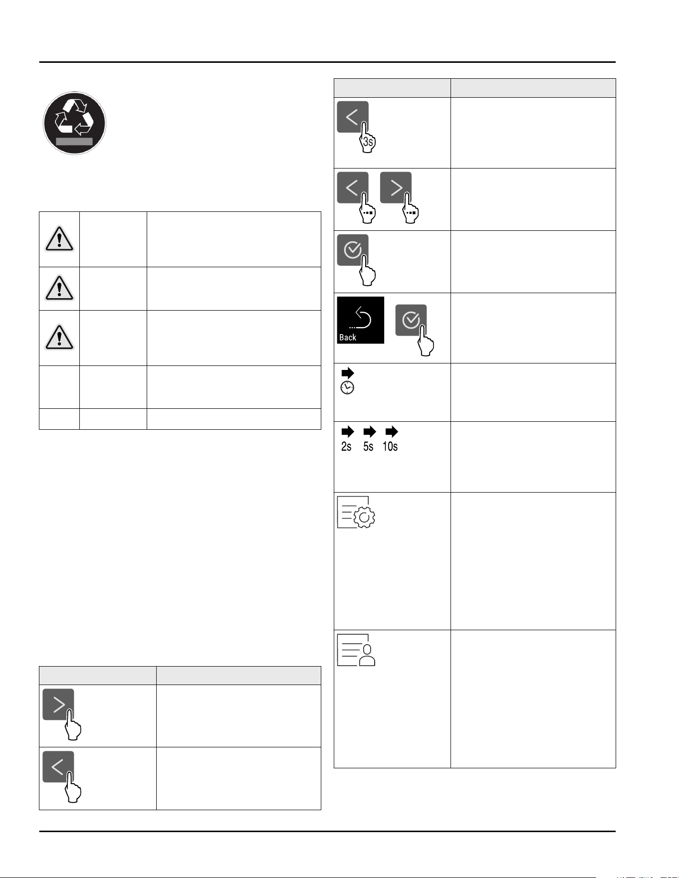
3.1 Navigation and symbol explana‐
tion
In the illustrations, different symbols are used to navi‐
gate the display. The following table describes these
symbols.
Symbol
Description
Press the Next navigation
arrow:
Navigates to the next option in
the menu.
Press the Back navigation
arrow:
Jumps back one option in the
menu.
Symbol Description
Press and hold the Back navi‐
gation arrow for 3seconds:
Jumps back to the status
display in the main menu or
from the Settings menu.
Press the navigation arrow
several times in succession:
Navigates in the menu to the
desired function.
Press the Confirm symbol:
Activates/deactivates func‐
tion.
Opens submenu.
Press the Confirm symbol
together with the back icon:
Jumps back one menu level.
Arrow with clock:
It takes more than 10 seconds
for the following message to
appear in the display.
Arrow with a time indication:
It takes the specified amount
of time until the following
message appears in the
display.
“Open Settings menu”
symbol:
Navigates to the Settings
menu and opens the settings
menu.
If necessary: Navigate to the
desired function in the
Settings menu.
(see 3.2.1 Opening the Settings
menu)
“Open Advanced menu”
symbol:
Navigates to the Advanced
menu and opens the advanced
menu.
If necessary: Navigate to the
desired function in the
Advanced menu.
(see 3.2.2 Opening the
Advanced menu)
Functionality of the Touch display
* Depending on model and options 7
Symbol Description
No action for
10seconds
If you do not perform any
action on the display for
10 seconds, the display either
jumps back to the higher-level
menu or directly to the status
display.
Opening door and
closing it again
If you open the door and
immediately close it again, the
display jumps directly back to
the status display.
Note: Illustrations of the display are shown in the English
version.
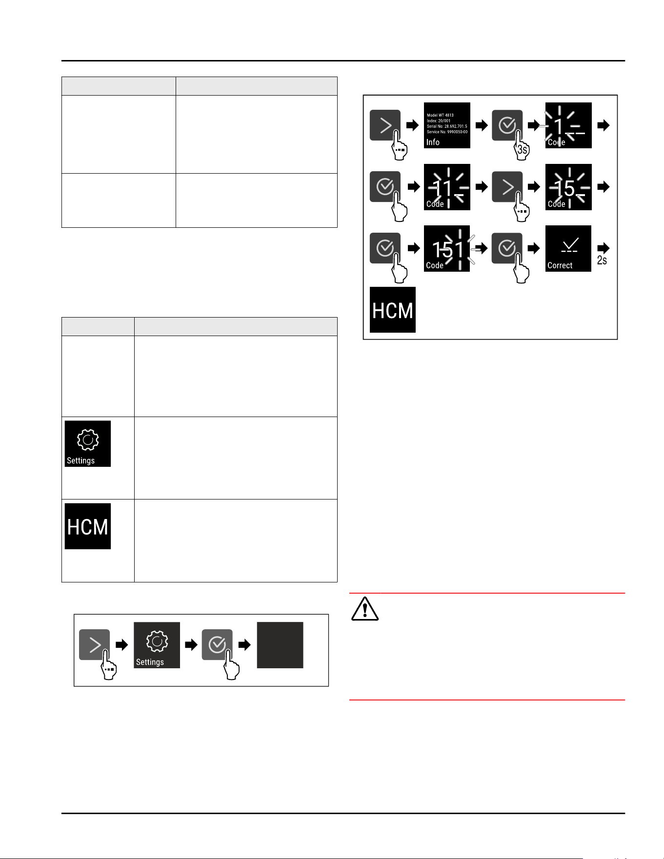
3.2 Menus
The appliance functions can be found in various
menus.
Menu
Description
Main menu When you switch the appliance on, you
are automatically in the main menu.
From here you can navigate to the
most important appliance functions, to
the Settings menu and to the
Advanced menu.
Settings
menu
The Settings menu contains additional
appliance functions for setting up your
appliance.
(see 3.2.1 Opening the Settings menu)
Advanced
menu
The advanced menu contains special
appliance functions for setting up your
appliance. Access to the Advanced
menu is protected by the numerical
code 151.
(see 3.2.2 Opening the Advanced menu)
3.2.1 Opening the Settings menu
Fig. 5 Example illustration
► Carry out action steps according to the illustration.
▷ Settings menu is open.
► If necessary: Navigate to the desired function.
3.2.2 Opening the Advanced menu
Fig.6Access with numerical code 151
► Carry out action steps according to the illustration.
▷ Expanded menu is open.
► If necessary: Navigate to the desired function.
3.3 Sleep mode
If you do not touch the display for 1 minute, the display
switches to sleep mode. In sleep mode, the display
brightness is dimmed.
3.3.1 Ending sleep mode
► Press any navigation key.
▷ Sleep mode is ended.
4 Start-up
4.1 Setup conditions
WARNING
Risk of fire due to moisture!
If live parts or the power cord get wet, this can cause a
short circuit.
► The appliance is designed for use in enclosed
spaces. Do not operate the appliance in open space
or in damp areas or where there is spray.
Start-up
8 * Depending on model and options
4.1.1 Setup location
WARNING
Leaking refrigerant and oil!
Fire. The refrigerant contained within the appliance is
environmentally friendly, but flammable. The oil
contained within the appliance is flammable. Escaping
refrigerant and oil can ignite if they are of high enough
concentration and are exposed to an external heat
source.
► Do not damage the pipelines of the coolant circuit
and the compressor.
-
Do not setup the appliance in direct sunlight, next to
an oven, radiator or similar.
-
The best place to set up the appliance is a dry and
well ventilated room.
-
If the appliance is set up in a very humid environ‐
ment, condensation can form on the outside of the
appliance.
Always ensure sufficient airflow and ventilation in
the setup location.
-
The more refrigerant there is in the appliance, the
larger the space it is installed in must be. If the
space is too small, any leak may create a flammable
mixture of gas and air. For every 8 g (0.28 oz) of
refrigerant, the installation space must be at least
1m
3
(35.5ft
3
). Specifications on the refrigerant in the
appliance can be found on the serial tag plate inside
the appliance.
-
The floor of the setup location must be horizontal
and even.
-
The setup location must be able to withstand the
weight of the appliance plus the weight when
stocked to maximum capacity. (see 9.1 Technical
data)
-
Use in hazardous areas is not permitted.
4.1.2 Electrical connection
WARNING
Danger of fire due to incorrect positioning!
If the power supply cable or plug touches the back of
the appliance, the vibration can damage the power
supply cable or the plug resulting in a short circuit.
► Make sure the power supply cable is not trapped
under the appliance when you position the appli‐
ance.
► Install the appliance so that it does not touch any
plugs or power cables.
► Do not connect any appliances to sockets in the area
of the back of the appliance.
► Do not place and operate power strips/power
distributors and other electronic devices (such as
halogen transformers) at the back of the appliances.
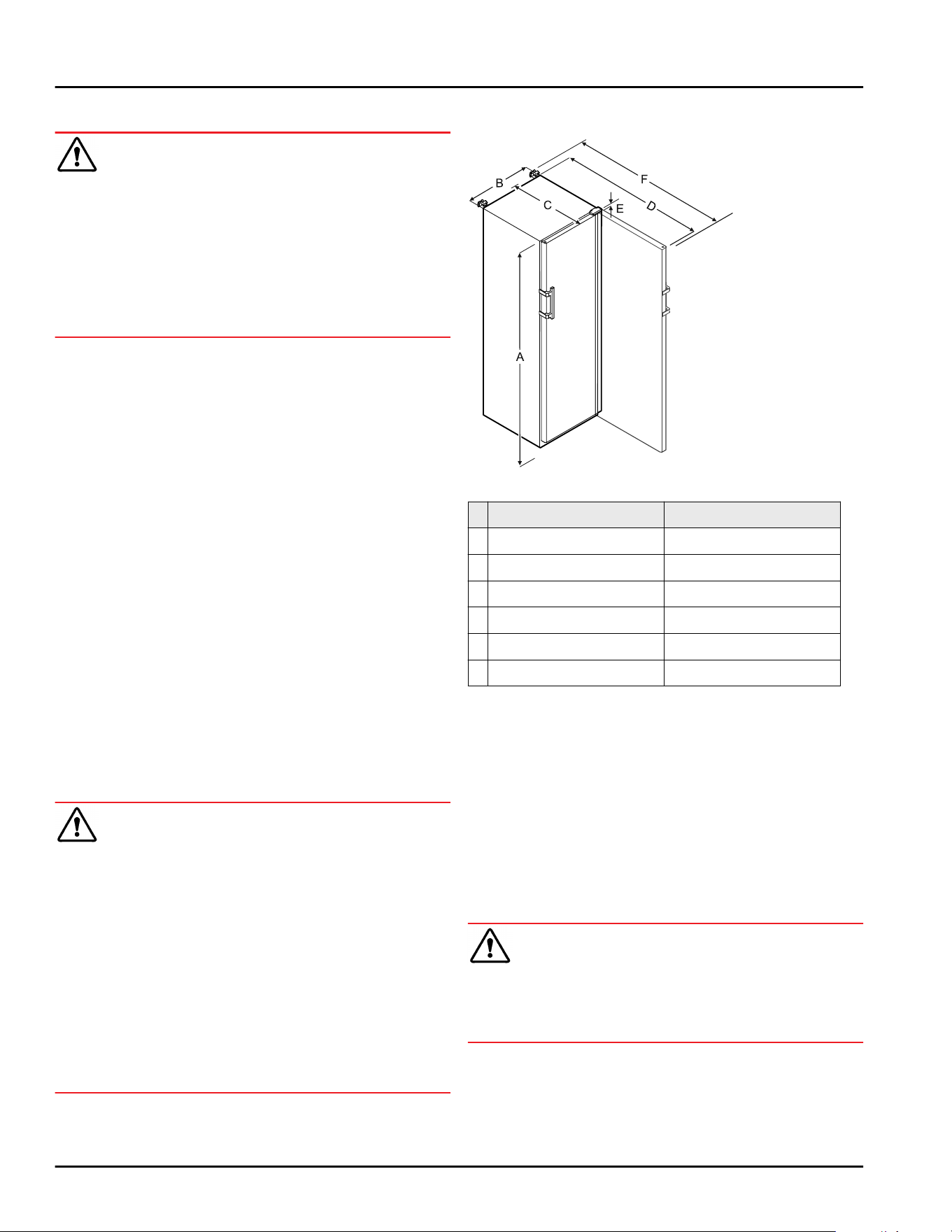
4.2 Appliance dimensions
Fig.7
SRFfg 3501
SRFfg 5501
A 1684mm(66 5/16in) 1684mm(66 5/16in)
B 597mm(23 1/2in) 747mm(29 7/16in)
C 664mm(26 1/8in) 779mm(30 11/16in)
D 1203mm(47 3/8in) 1468mm(57 13/16in)
E 23mm(7/8in) 23mm(7/8in)
F 1241mm(48 7/8in) 1506mm(59 5/16in)
A = appliance height including feet/castors
B = appliance width without handle [handle depth =
45mm(1 6/8in)]
C = appliance depth without handle [handle depth =
45mm(1 6/8in)]
D = appliance depth with door open
E = hinge height
F = appliance depth with protruding handle and anti-
tipping device
4.3 Transporting the appliance
WARNING
Danger of injury and damage due the equipment falling
over!
► Pay attention to the evenness of the ground and
ramps when transporting the equipment.
Observe the following when transporting the appli‐
ance:
► Transport the appliance upright.
► Use two people when transporting the appliance.
During the first use:
Start-up
* Depending on model and options 9
► Transport the appliance packaged.
During appliance transport or at first use (e.g. when
moving or cleaning):
► Empty the appliance.
► Secure the door against undesired opening.
4.4 Unpacking the appliance
► Check the appliance and the packaging for transport
damage. Contact the supplier immediately if you
suspect any damage. Do not connect the appliance
to the power supply.
► Remove all packaging materials from the rear or the
side walls of the fridge that may prevent proper
installation or prevent air flow and ventilation.
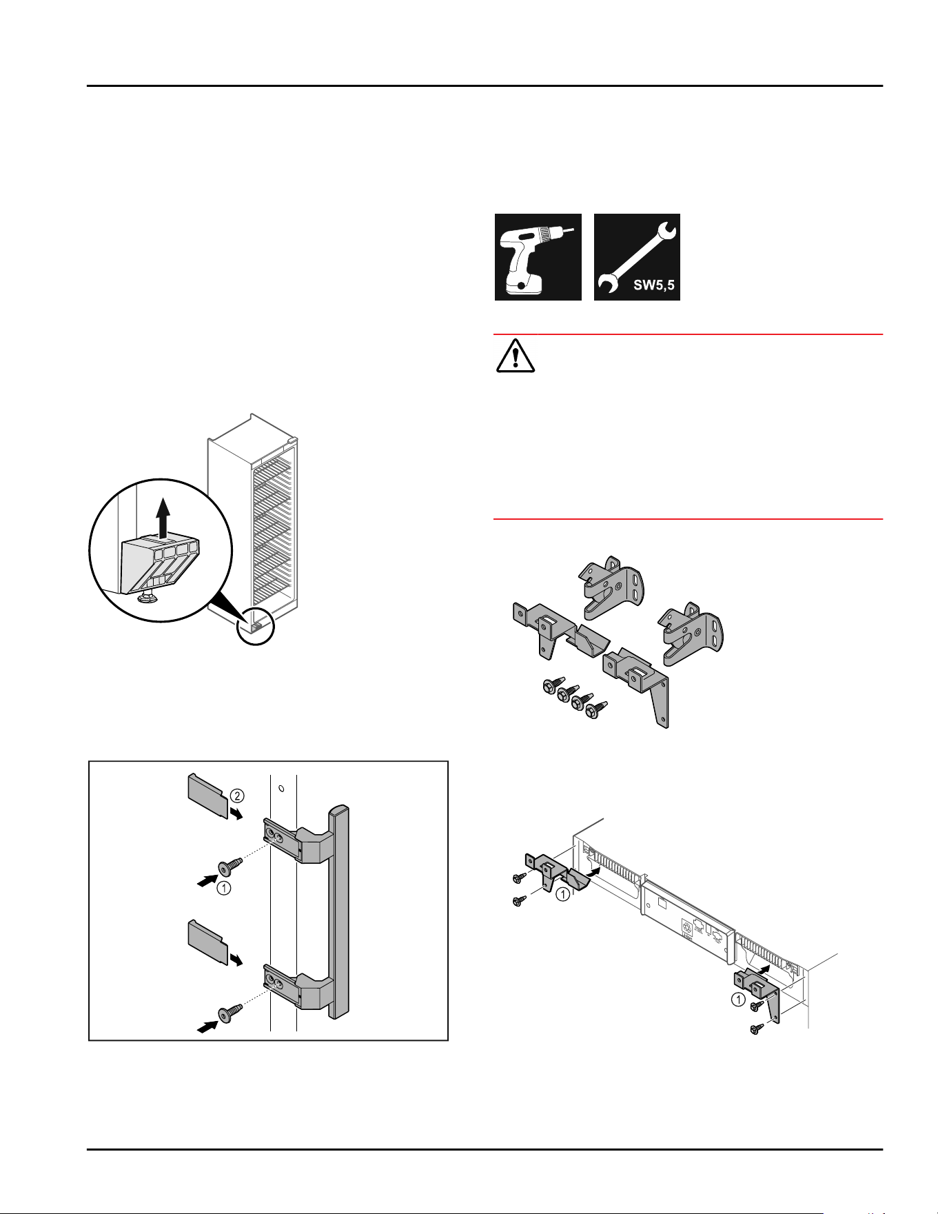
4.5 Removing the transport lock
Fig.8
► Remove transport lock in upwards direction.
▷ Base holder remains on the appliance.
4.6 Installing the door handle
Fig.9
► Attach handle from accessory kit to the door using
supplied screws Fig.9(1).
► Put on cover Fig.9(2).
►
Insert the plug from the enclosed package on the
other side. *
4.7 Mounting the anti-tipping device
Tools
Fig. 10
WARNING
Danger of injury and damage due to appliance tipping
over!
Risk of death and damage to the appliance. An appli‐
ance without a mounted anti-tip bracket may tip over
while e. g. opening the door or pulling out the shelves.
► Before putting the appliance in operation: Always
install the anti-tip bracket as described in the
instructions.
Prevent appliance from tipping over.
Fig.11
The tilt protection is enclosed with the appliance. It is
comprised of two retaining parts, two securing hooks
and four self-tapping screws (4 x 14).
Fig.12
► Assemble the retaining parts Fig. 12 (1) with the self-
tapping screws on the appliance.
► Push appliance with retaining parts mounted against
the wall.
Start-up
10 * Depending on model and options
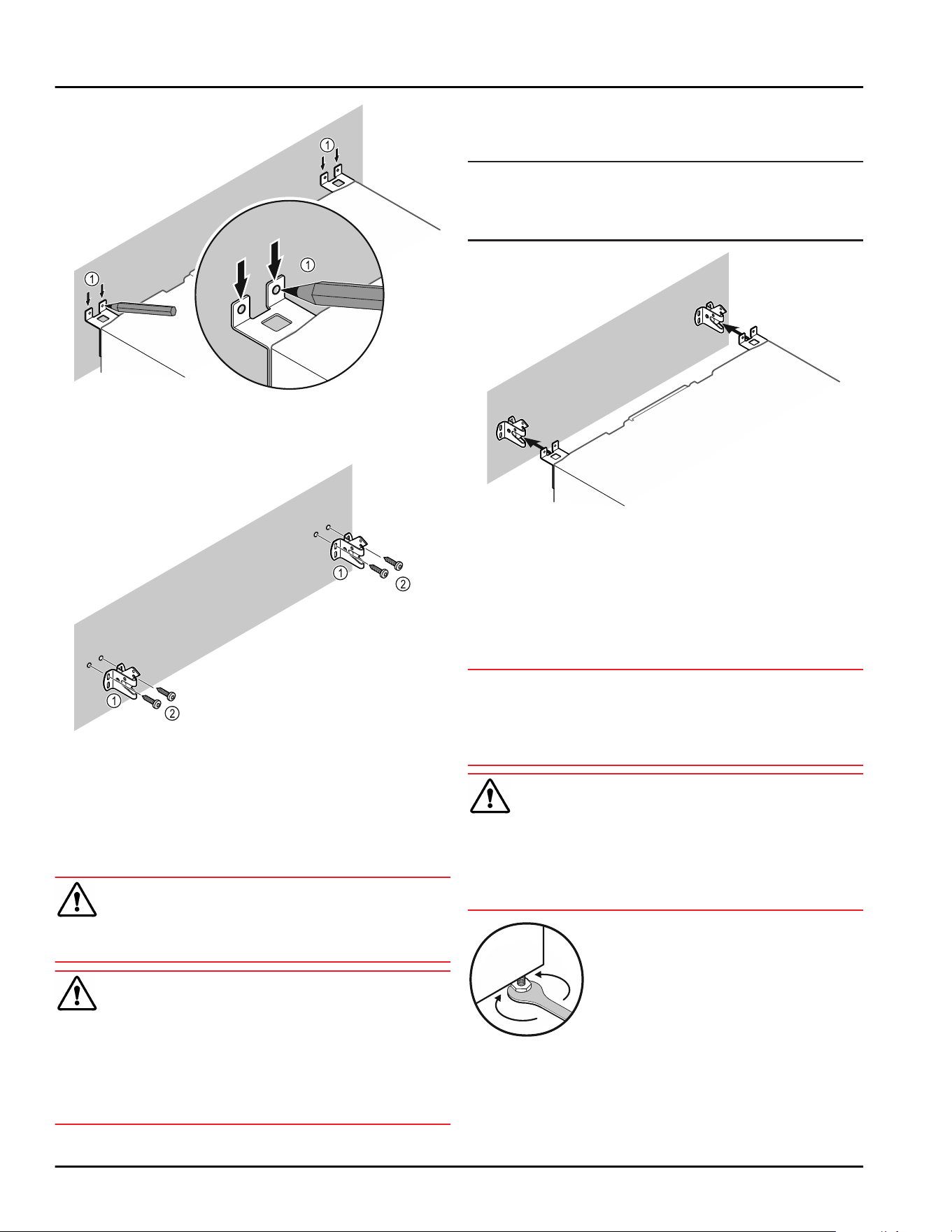
Fig.13
► Make markings on the wall Fig.13(1).
► Remove appliance.
Fig. 14
Use fixing material (e.g. wall anchors) which is
appropriate for the nature of the wall (wood,
concrete) and sufficient attachment points .
► Attach retaining hooks.
4.8 Setting up the appliance
CAUTION
Risk of injury and damage.
► Use 2 people to set up the appliance.
CAUTION
Risk of injury and damage.
The door can strike against the wall and become
damaged as a result. In the case of glass doors, the
damaged glass can cause injuries.
► Protect the door from striking against the wall.
Attach a door stopper, e.g. felt stopper, to the wall.
► Connect all necessary components (e.g. power
cable) to the back of the appliance and route to the
side.
Note
Cables can be damaged.
► Do not crush the cable when pushing the appliance
back.
Fig. 15
► Slide the appliance up against the wall so that the
retaining parts latch into the retaining hooks.
▷ The appliance is now secured against tipping.
▷ It can be released by folding back the retaining
hooks.
4.9 Leveling out the appliance
NOTICE
Appliance body can become deformed and door will not
close.
► Align appliance horizontally and vertically.
► Compensate for uneven floors using adjustable feet.
WARNING
Incorrect height adjustment of the adjustable foot!
Severe or fatal injuries. Incorrect height adjustment
can cause the bottom part of the adjustable foot to
come loose and the appliance to tip over.
► Do not unscrew the adjustable foot too far.
Fig. 16
Raising appliance:
► Turn adjustable foot clockwise.
Lowering appliance:
► Turn adjustable foot counterclockwise.
Start-up
* Depending on model and options 11
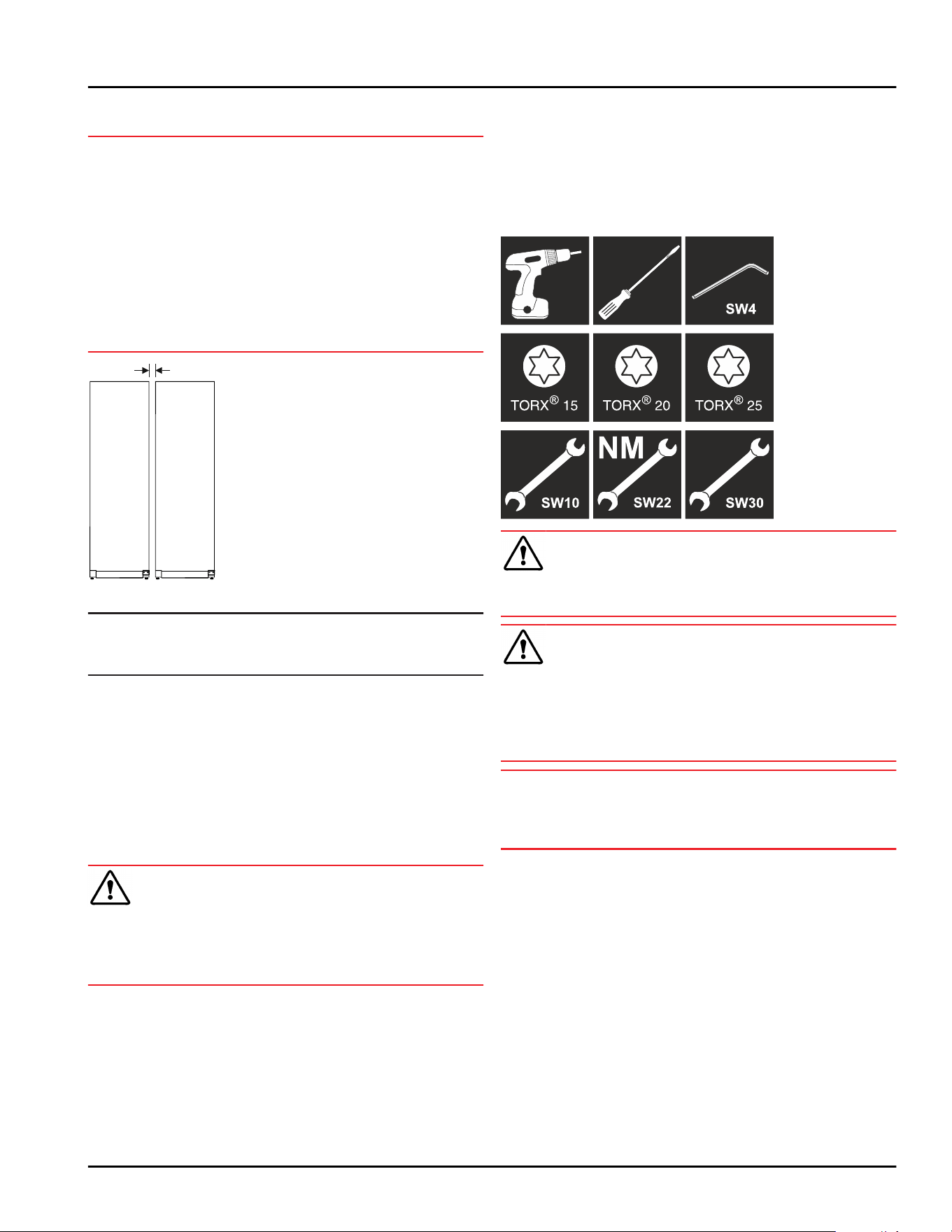
4.10 Setting up multiple appliances
NOTICE
Risk of damage due to condensation between the side
walls.
► Do not set up the appliance directly next to another
refrigeration appliance.
► Set up appliances with a space of 3 cm (1.18 in)
between appliances.
► Only set up multiple appliances up to temperatures
of 35 °C (95 °F) and 65 % humidity next to one
another.
► At higher levels of humidity, increase the space
between appliances.
Fig. 17 Side-by-side set up
Note
A side-by-side kit is available as an accessory via
Liebherr Customer Service. (see 9.3 Customer Service)
4.11 After setup
► Peel off the protective films. *
► Clean the appliance. (see 8.3Cleaning the appliance)
► If necessary: Disinfect the appliance.
► Keep the invoice so you have the appliance and
dealer information available if needed.
4.12 Disposal of packaging
WARNING
Danger of suffocation from packaging materials and
films!
► Do not allow children to play with packaging mate‐
rials.
The packaging is made from recyclable materials:
-
Corrugated card/cardboard
-
Parts made of foamed polystyrene
-
Films and bags from polyethylene
-
Packing bands from polypropylene
-
Wood frame nailed together with a polyethylene
window*
►
Take the packaging material to an official collection
point.
4.13 Reversing the door opening
direction
Tools
WARNING
Risk of injury if the door is not reversed correctly!
► Have a specialist change the door hinge.
WARNING
Risk of injury and material damage due to heavy door!
► Only perform the conversion if you can carry a
weight of 25 kg(55.11lb).
► Always have someone help you carry out the conver‐
sion.
NOTICE
Live parts!
Damage to electrical components.
► Pull the power plug before changing the door hinges.
► Open the door.
Start-up
12 * Depending on model and options
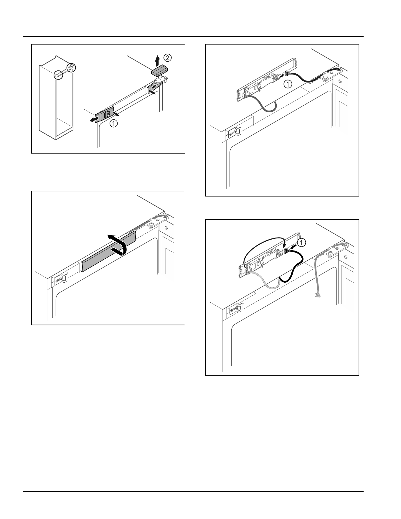
Fig. 18
► Unlatch the front covers Fig. 18 (1) on the inside and
remove them sideways.
► Lift off the upper cover Fig. 18(2).
Fig. 19
► Unlatch the middle cover and remove it.
Fig.20
► Disconnect the plug Fig.20(1) from the circuit board.
Fig.21
► Connect the plug Fig.21(1) to the circuit board.
Start-up
* Depending on model and options 13
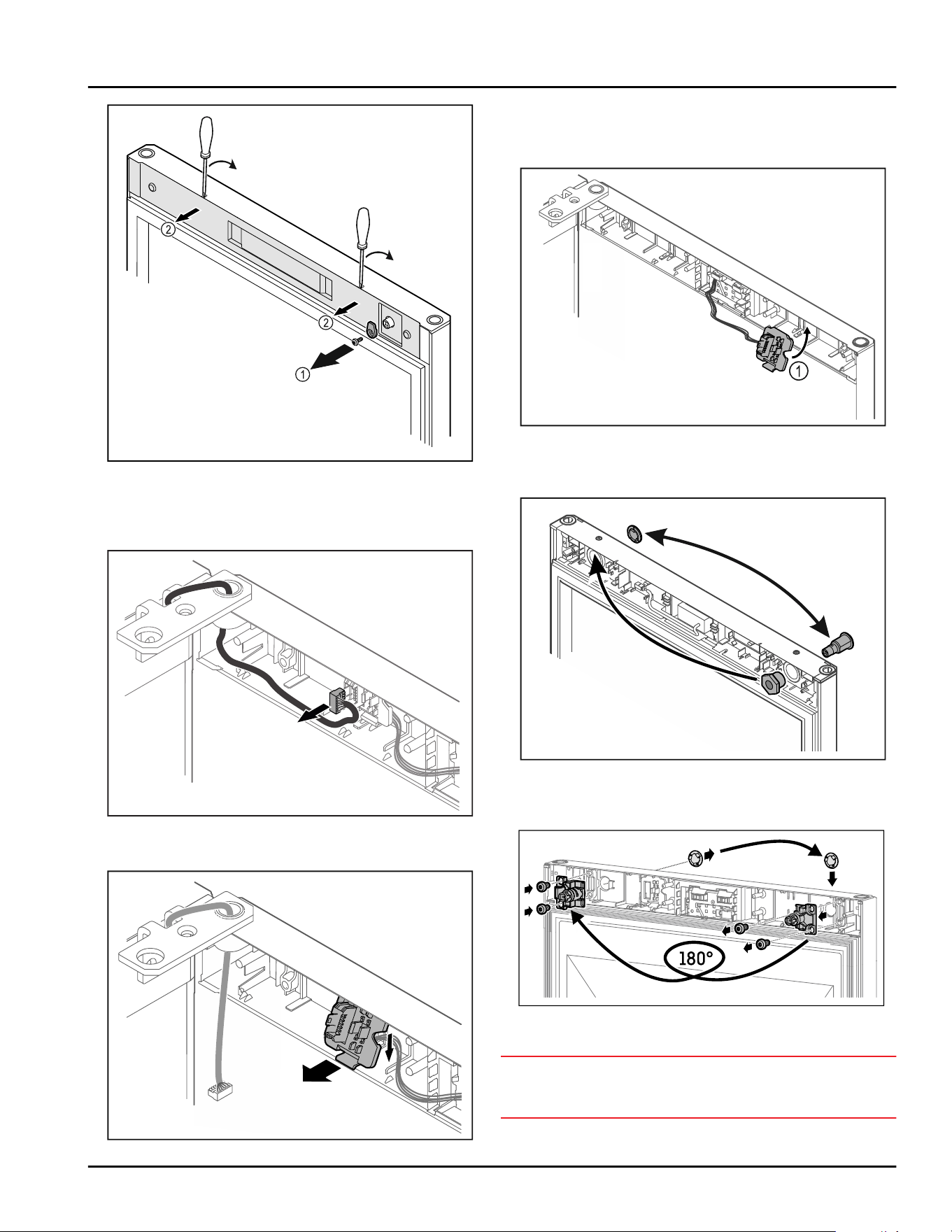
Fig.22
► Unscrew the door latch Fig.22(1).
► Unlatch the cover Fig. 22 (2) with a small screwdriver
and remove it.
Fig.23
► Remove the plug from the plug holder.
Fig. 24 The installation position of the plug holder can be
rotated by 180°.
► Disengage the plug holder.
Fig.25
► Snap in the plug holder Fig. 25 (1) on the opposite
side.
Fig. 26
► Put the lock and cover on the opposite side.
-or-
Fig.27
► Put the lock and cover on the opposite side.
NOTICE
Risk of injury if the door tips out!
► Hold the door.
Start-up
14 * Depending on model and options
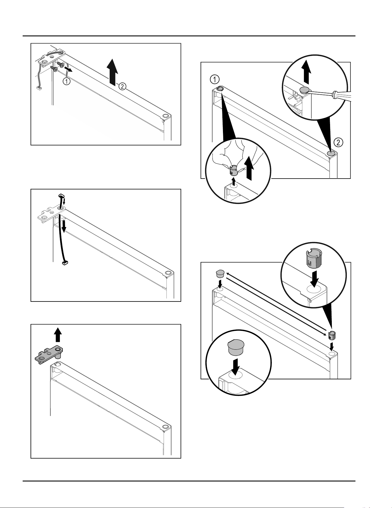
Fig.28
► Unscrew the hinge Fig.28(1).
► Lift the door with the hinge straight up by Fig. 28 (2)
roughly 200mm(7.87in) and take it off.
► Carefully place the door on a soft surface.
Fig.29
► Carefully pull out the cable.
Fig.30
►
Pull out the hinge.
Fig.31
► Pull out the hinge bushing Fig.31(1) with your fingers.
► Carefully lift the cover plug Fig. 31 (2) with a slotted
screwdriver and pull it out.
Fig.32
► Insert hinge bushing and cover plug on the opposite
side (the flattened sides face outwards).
Start-up
* Depending on model and options 15
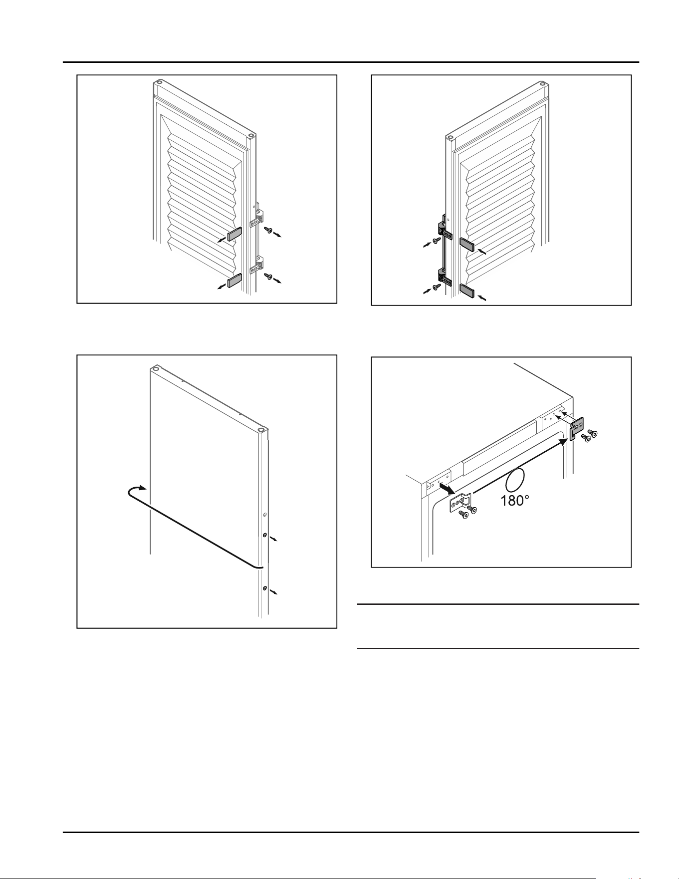
Fig. 33 Insulated door
► Remove the panels.
► Unscrew the handle.
Fig.34
► Put the stopper on the opposite side.
Fig. 35 Insulated door
► Screw the handle onto the opposite side.
► Attach the panels.
Fig.36
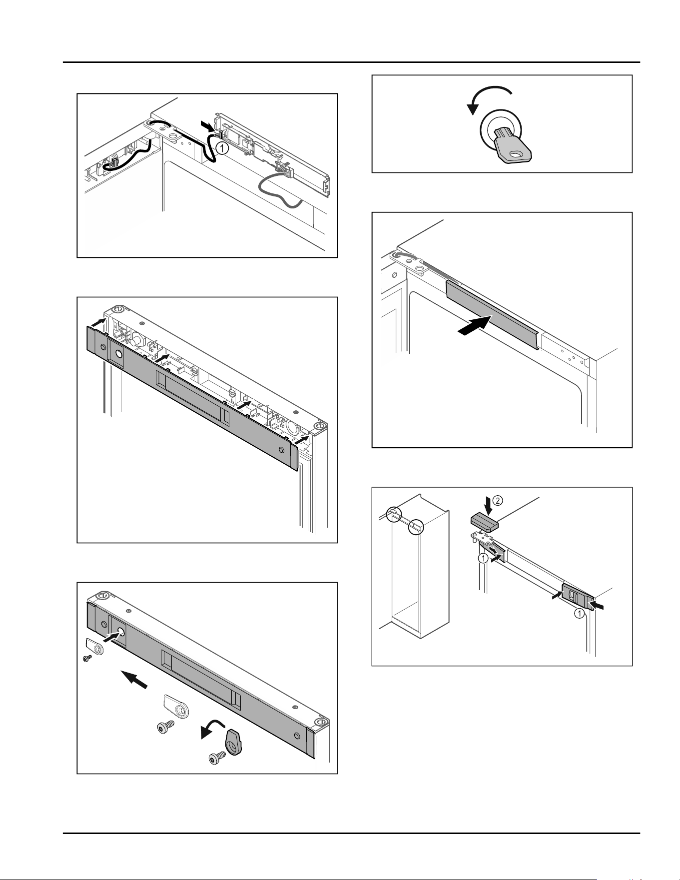
► Put the closing bracket on the opposite side.
Note
The holes are pre-marked and must be pierced with the
self-tapping screws.
Start-up
16 * Depending on model and options
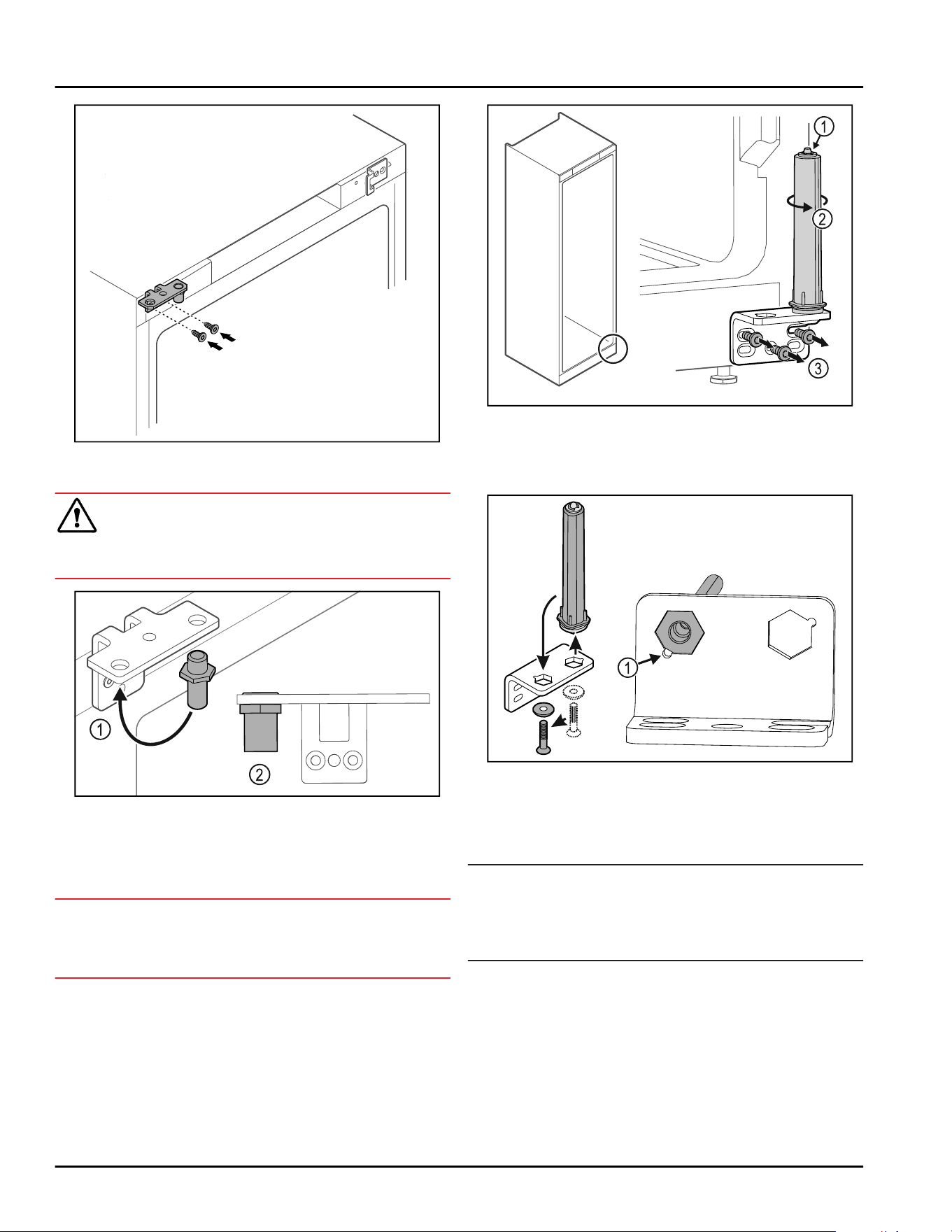
Fig.37
► Move the hinge to the opposite side.
WARNING
Risk of injury and material damage if the door tips out!
► Tighten the bearing pins to the specified torque.
Fig.38
► Put the pin back into the hinge Fig.38(1).
► Tighten the pin Fig. 38 (2) to a torque of
12 Nm(9 ft-lb).
► Unscrew the hinge again.
NOTICE
Risk of injury due to tensioned spring!
► Do not disassemble the door closing system
Fig. 39(1).
Fig. 39
► Turn the closing system Fig. 39(2) until it clicks.
▷ The tension of the closing system is released.
► Unscrew the hinge Fig. 39(3).
Fig.40
► Put the door closing system in the hinge.
► Make sure the pin chamfer Fig. 40 (1) faces the round
hole when you put it in.
-or-
Note
Incorrect alignment of the height adjustment washers.
Nuts no longer have sufficient hold.
► The washer must luck into the underside of the
closing system.
Start-up
* Depending on model and options 17
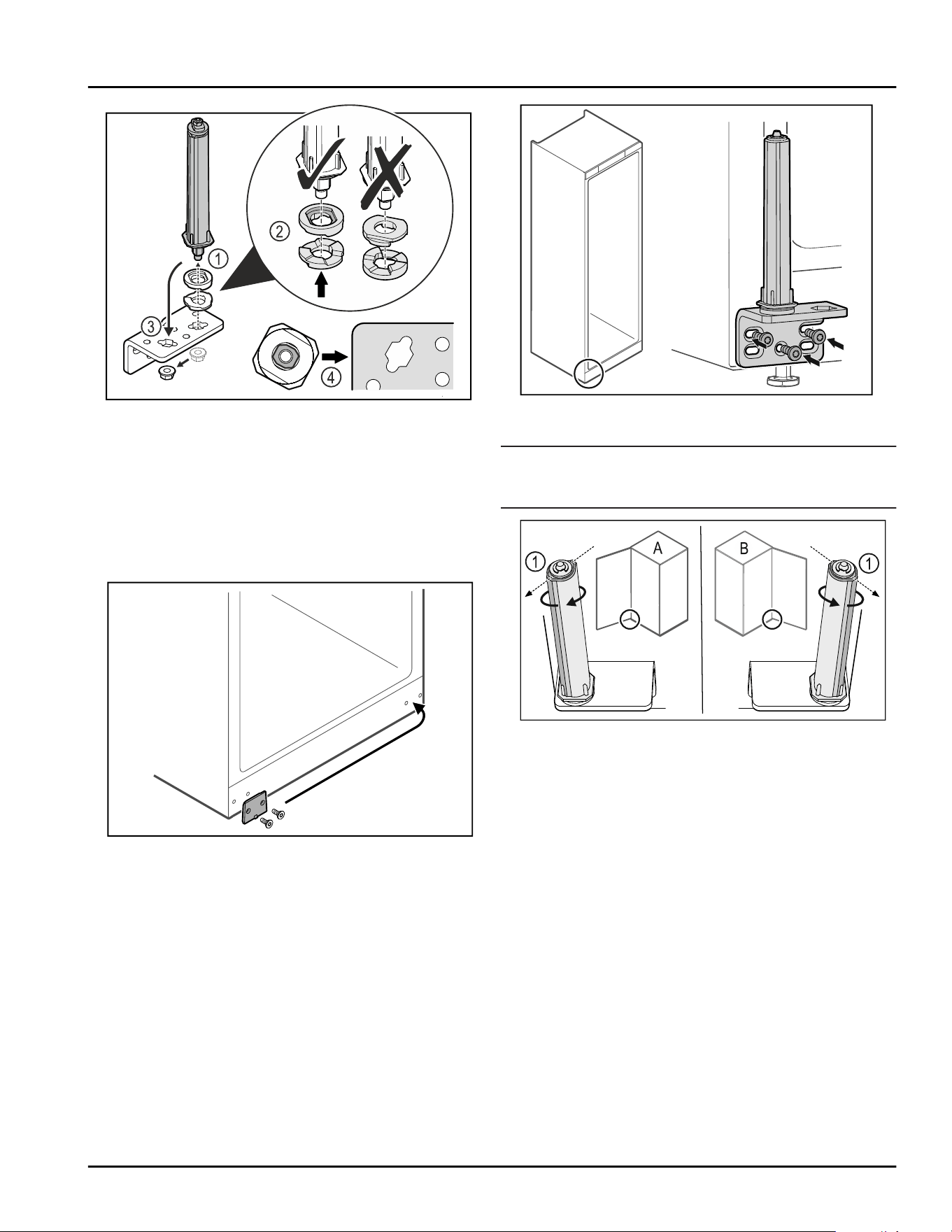
Fig. 41
► Loosen the nut and remove the door closing system
Fig. 41(1).
► Observe the correct alignment of the height adjust‐
ment washers Fig. 41(2).
► Put the door closing system in the hinge fix in place
with the nut Fig. 41(3).
► Observe the correct alignment of the door closing
system when doing so Fig. 41(4).
Fig. 42
► Put the cover plate on the opposite side.
Fig.43
► Screw the hinge onto the opposite side.
Note
Correct alignment and tension are important for the
closing system to work properly.
Fig. 44 Left-hinged (A) / Right-hinged (B)
► Turn the closing system against the resistance until
the bar of the closing system Fig. 44 (1) points
outwards.
▷ The closing system automatically stays in this posi‐
tion.
▷ The closing system is now aligned and pretensioned.
Start-up
18 * Depending on model and options
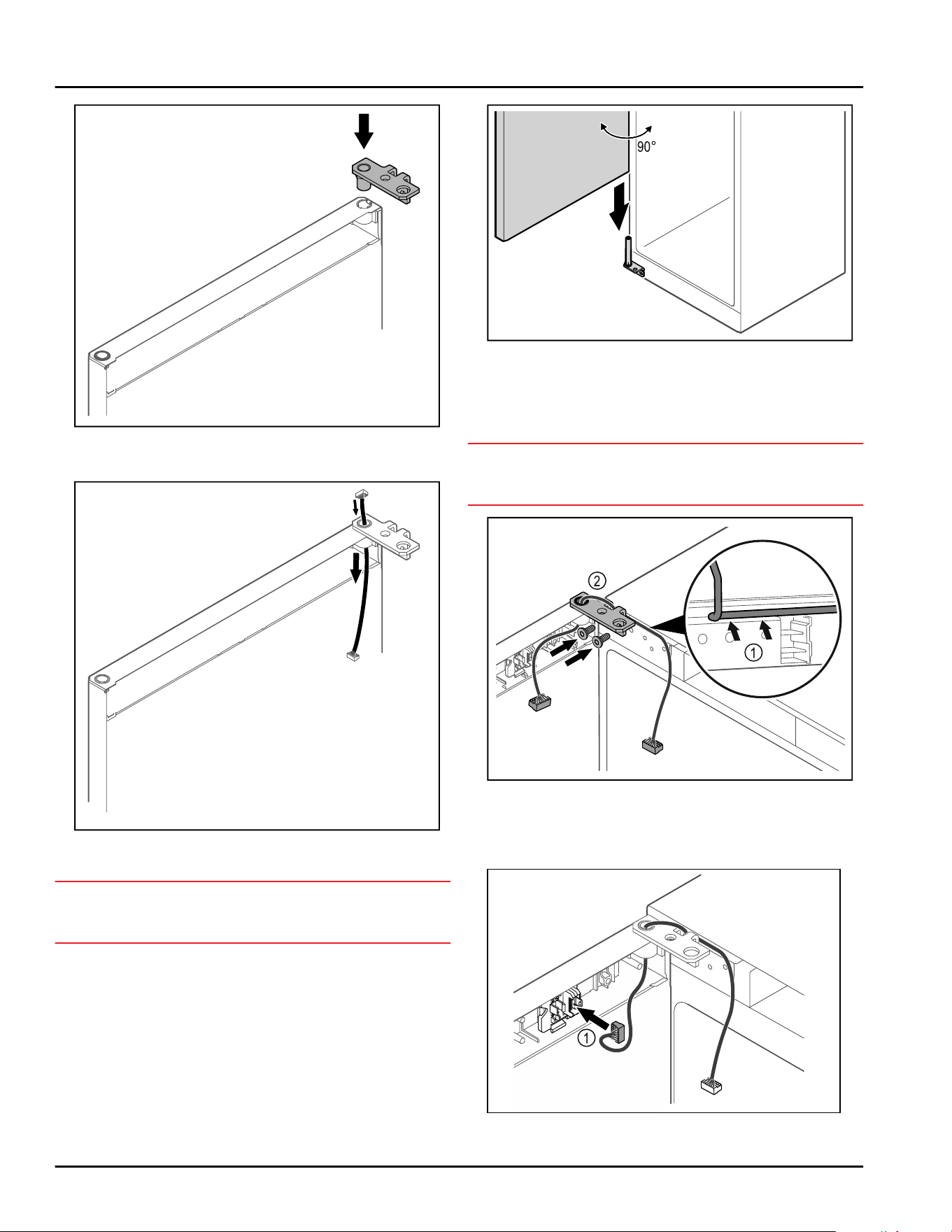
Fig.45
► Put the hinge into the door.
Fig.46
► Carefully push the cable through.
NOTICE
Risk of injury if the door tips out!
► Hold the door.
Fig. 47
► Together with a second person, lift the door from the
ground.
► Carefully put the door on the closing system with
the door opened at a 90° angle.
NOTICE
Material damage due to incorrect mounting!
► Do not pinch the cable when mounting the hinge.
Fig.48
► Feed the cable through the recess in the hinge and
lay it carefully Fig.48(1).
► Screw on the hinge Fig.48(2).
Fig. 49
Start-up
* Depending on model and options 19
► Put the plug Fig. 49(1) in the plug holder.
Fig.50
► Connect the plug Fig.50(1) to the circuit board.
Fig.51
► Set the cover back in place.
Fig.52
► Screw on the door latch.
Fig.53
► Open the door.
Fig.54
► Snap in the middle cover.
Fig.55
► Hook in the front covers Fig. 55 (1) on the side and
snap them into place on the inside.
► Snap on the top cover Fig.55(2) from above.
► Close the door.
▷ The door has now been reversed.
4.14 Aligning the door
If the door is not straight, you can adjust it on the
lower hinge.
Start-up
20 * Depending on model and options
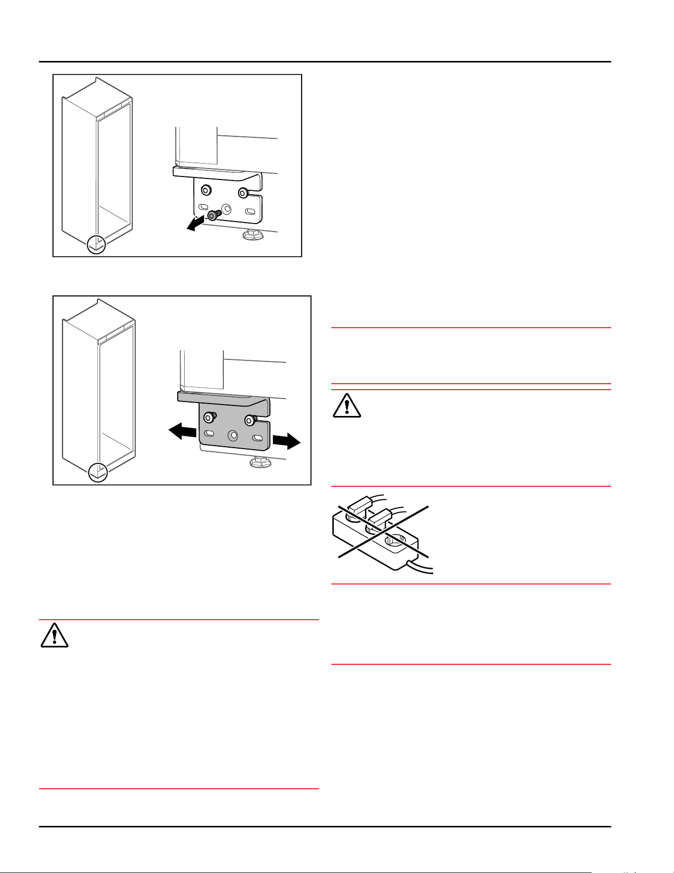
Fig.56
► Remove the middle screw on the lower hinge.
Fig.57
► Slightly undo both screws and move the door with
the hinge to the left or right.
► Fully tighten the screws (the middle screw is no
longer needed).
▷ The door is now straight.
4.15 Connecting the appliance to the
power supply
WARNING
Danger of electric shock and injury due to damaged
appliance or damaged mains cable!
Cuts and fatal injury. If the appliance or the mains
cable is damaged during transport, you may be electro‐
cuted. You could also cut yourself on damaged parts of
the appliance housing.
► Check the appliance and the mains cable for
damage after transport.
► Never put the appliance into operation if the appli‐
ance or the mains cable are damaged.
► Contact Customer Service.
You can connect your appliance to the mains using the
power cable supplied separately. The mains power
cable has an appliance coupler at one end and a mains
plug at the other end.
Make sure that the following requirements are fulfilled:
-
The appliance and power cable are undamaged.
-
The appliance is set up in accordance with the regu‐
lations. (see 4.5 Removing the transport lock)
-
Requirements for the electrical connection are met.
(see4.1 Setup conditions)
-
Dimensions for connection in accordance with regu‐
lations are known and observed.
-
Mains voltage and frequency correspond to the
specifications on the type plate.
-
The socket is grounded and fused in accordance
with regulations.
-
The tripping current for the fuse is between 10 A and
16A.
-
Outlet is easily accessible and is not behind the
appliance.
NOTICE
Danger of damage to incorrect operation!
Damage to the electrical components of the appliance.
► Only use the supplied power cable.
WARNING
Danger of fire due to incorrect connection!
Burns.
Damage to the appliance.
► Do not use an extension cord.
► Do not use a multipoint connector strip.
NOTICE
Danger of damage to incorrect connection!
Damage to the appliance.
► Do not connect the appliance to a stand-alone
inverter, e.g. solar power systems and petrol genera‐
tors.
► Connect the mains plug of the power cord to the
power supply. Ensure the main plug is firmly plugged
into the outlet.
▷ The standby symbol appears in the display.
▷ If no action is taken within 60 seconds: Standby
symbol fades or disappears.
▷ Appliance is connected. For initial commissioning,
see the next chapter or the operating instructions.
Start-up
* Depending on model and options 21
4.16 Switching on the appliance (first
use)
Make sure that the following requirements are fulfilled:
- Appliance is set up and connected.
- All adhesive strips, adhesive and protective films
and transport locks are removed from inside and
outside the appliance.
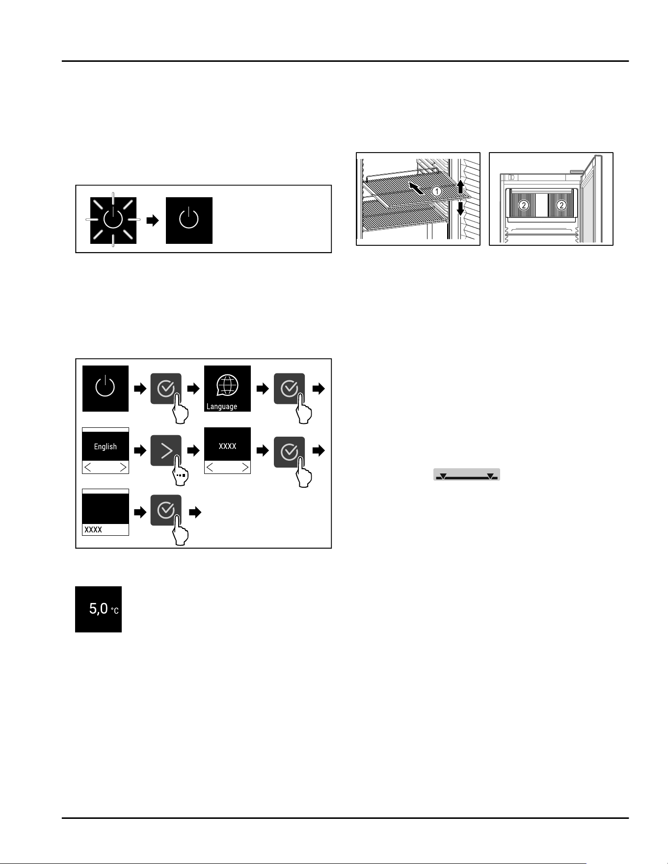
Fig. 58 Example illustration
The standby symbol flashes until the startup process is
complete.
The standby symbol is shown in the display.
If the appliance has been supplied with factory
settings, the screen language first needs to be
selected when using for the first time.
3s
Fig. 59
► Carry out action steps according to the illustration.
Fig.60
▷ The appliance is switched on once the temperature
appears on the display.
▷ The temperature display flashes until the set
temperature is reached.
5 Storage
5.1 Information regarding storing
items
Fig. 61 Example illustration Fig. 62
When stocking items, observe the following:
❑
If there are adjustable shelves Fig. 61 (1), position
them as required.
❑
Observe maximum load weight. (see 9.1 Technical
data)
❑
Do not stock appliance until the storage temperature
has been reached (maintain cold chain).
❑
Ventilation slots Fig. 62 (2) for recirculation fan in the
interior must be kept clear.
❑
Refrigerated goods must not touch the rear wall.
❑
Refrigerated goods do not stick out beyond the
shelves.
❑
Keep liquids in closed containers.
❑
Leave space when storing items for refrigeration to
ensure adequate air circulation.
❑
Do not stack refrigerated products above the indi‐
cated height.
This is important for free air circulation and even
temperature distribution in the interior.
❑
Do not store refrigerated goods under the defrost
water bowl.
6 Use
6.1 Control and display elements
The display provides a quick overview of the current
appliance status, the temperature setting, the status
of functions and settings as well as alarm and error
messages.
It is operated using the navigation arrows and confir‐
mation symbol.
Functions can be activated or deactivated and settings
values can be changed.
Storage
22 * Depending on model and options
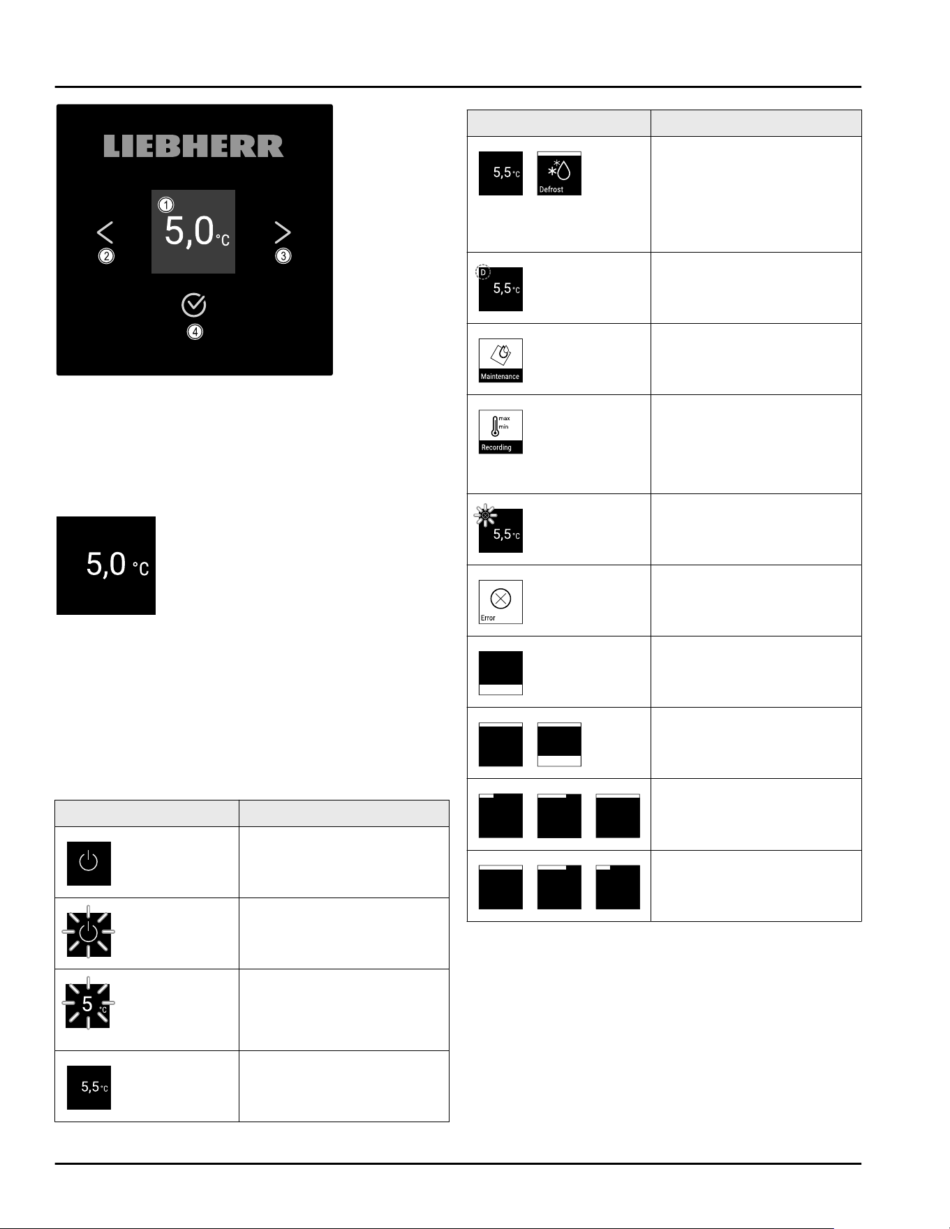
Fig.63Display
(1)
Status display (3) Forward navigation
arrow
(2) Backward navigation
arrow
(4) Confirm
6.1.1 Status display
Fig. 64 Status display with actual temperature
The status display shows the actual temperature and
is the home display. You navigate from here to the
other functions and settings. The status display may
show a range of display symbols.
6.1.2 Display symbols
The display symbols provide information about the
current status of the appliance.
Symbol
Appliance status
Standby
Appliance is switched off.
Flashing standby symbol
Appliance is starting up.
Flashing temperature
Target temperature not yet
reached. Appliance cooling
to set temperature.
Temperature display
Displays the current interior
temperature.
Symbol Appliance status
Display alternating
between temperature/
defrost symbol with white
bar
Appliance is in manual
defrosting mode.
D in the display
Appliance is in DemoMode.
Maintenance reminder
The time set interval has
expired.
Data memory full
The data memory (999
hours) is full. From now, the
oldest data will be over‐
written.
Flashing symbol
A fault is still present.
Error symbol
Appliance is still malfunc‐
tioning.
White bar at the bottom
Submenu
White bar at the top
Default, active setting or
active value.
Increasing bar
Press button for 3 seconds
to activate setting.
Decreasing bar
Press button for 3 seconds
to deactivate setting.
Status display symbols
6.1.3 Acoustic signals
A signal sounds in the following cases:
-
If a function or a value is confirmed.
-
If a function or a value can neither be activated nor
deactivated.
-
As soon as a fault occurs.
-
If there is an alarm message.
The alarms can be switched on and off in the customer
menu.
Use
* Depending on model and options 23
6.2 Appliance functions
6.2.1 Notes on the appliance functions
The appliance functions are set at the factory so that
your appliance is fully functional.
Before you alter, activate or deactivate the appliance
functions, make sure that the following requirements
are met:
❑
You have read and understood the descriptions of
how the display works. (see 3 Functionality of the
Touch display)
❑
You have familiarized yourself with the operating
and display elements of your appliance.
(see6.1 Control and display elements)
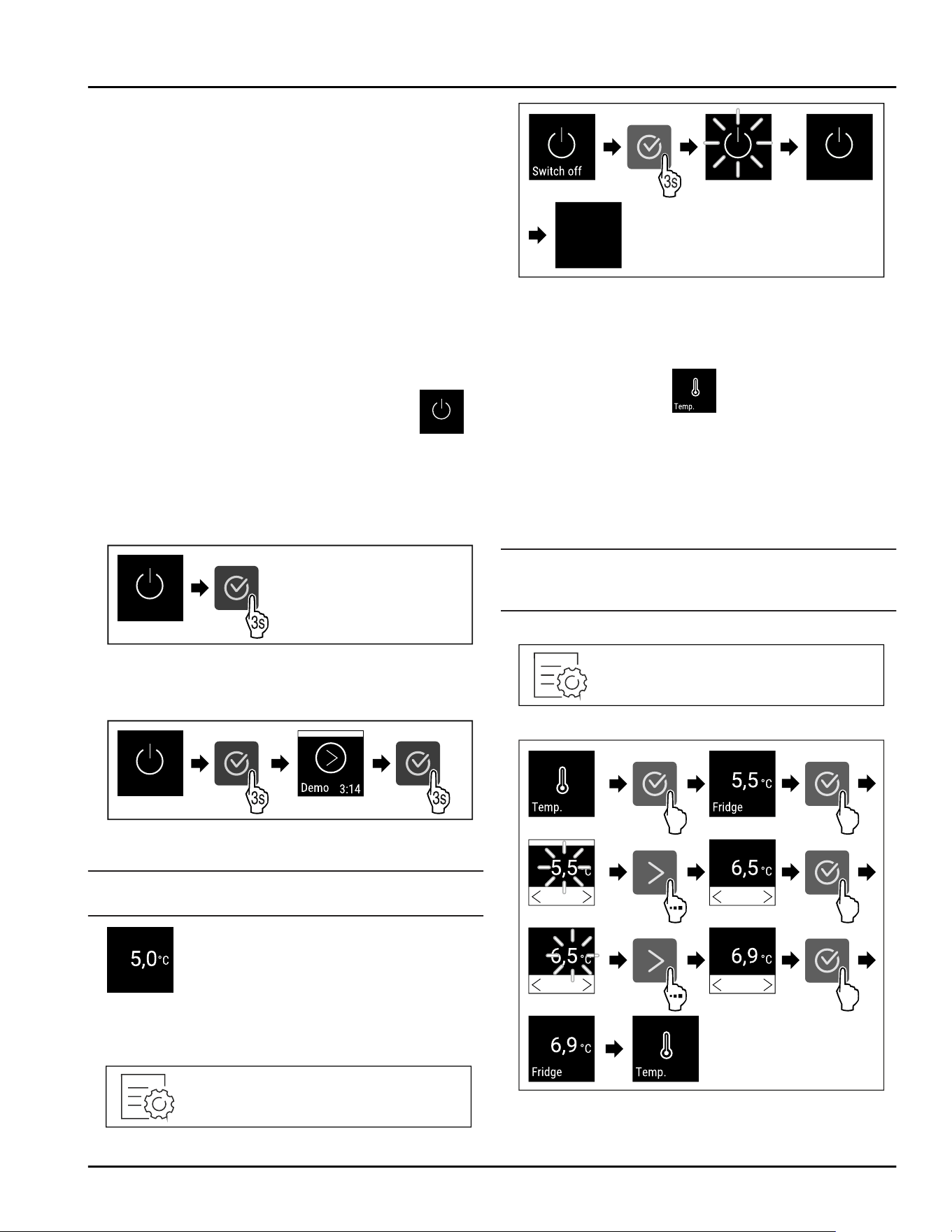
6.2.2 Switching appliance on and off
Using this setting the entire appliance can be switched
on and off.
Switching on the appliance
Without activated DemoMode:
Fig.65
► Carry out action steps according to the illustration.
With activated DemoMode:
Fig.66
► Carry out action steps according to the illustration.
Note
Deactivate DemoMode before the countdown finishes.
Fig. 67
▷ The temperature appears on the display.
Switching off the appliance
Fig.68
Fig. 69
► Carry out action steps according to the illustration.
▷ Standby symbol is shown in the display.
▷ Display switches off after approximately 10 minutes.
6.2.3 Temperature
The temperature depends on the following factors:
-
How often the door is opened
-
How long the door is open for
-
The room temperature of the installation site
-
The type, temperature and amount of refrigerated
items
Note
The temperature may differ from the temperature
displayed in some areas of the interior.
Setting the temperature
Fig.70
Fig. 71 Changing temperature from 5.5°C(42°F) to
6.9°C(44°F)
► Carry out action steps according to the illustration.
Use
24 * Depending on model and options
▷ Temperature is set.
6.2.4 Temperature recording
The appliance displays the minimum and maximum
temperatures of the interior. The recording of these
temperatures starts automatically after the appliance
is switched on; they are recorded at one minute inter‐
vals. A note indicating that the data memory is full is
displayed after 999 hours (approx. 40 days). The
temperature recording should then be reset.
Note
We recommend resetting the temperature recording
once after reaching the set temperature when the
appliance is commissioned. This ensures that the value
displayed for the maximum temperature is a mean‐
ingful value.
Displaying temperature recording
The temperature recording displays the length of the
recording and the minimum and maximum tempera‐
tures measured during this period of time.
Fig.72
Fig.73
▷ Status screen with the temperature recordings is
displayed.
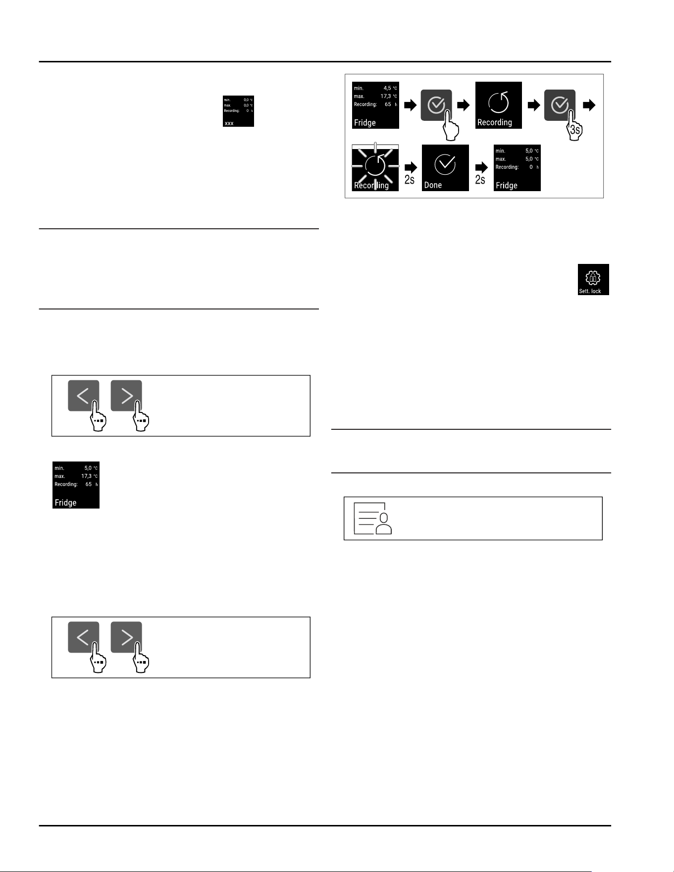
Resetting temperature recording
The displayed minimum and maximum temperatures
can be reset at any time. This deletes the displayed
values and the recording interval starts again.
Fig. 74
Fig.75
► Carry out steps according to the illustration.
▷ Temperature recording is reset.
▷ Reminder interval is reset.
6.2.5 Settings menu access protection
This setting enables the settings menu access protec‐
tion via a three-digit PIN code.
Application:
-
Prevent settings and functions being changed unin‐
tentionally.
-
Prevent the appliance from being switched off unin‐
tentionally.
-
Avoid unintentional temperature adjustment.
Note
► In the following examples, the PIN code set at the
factory:111 is used.
Activating the settings menu access protection
Fig. 76
Use
* Depending on model and options 25
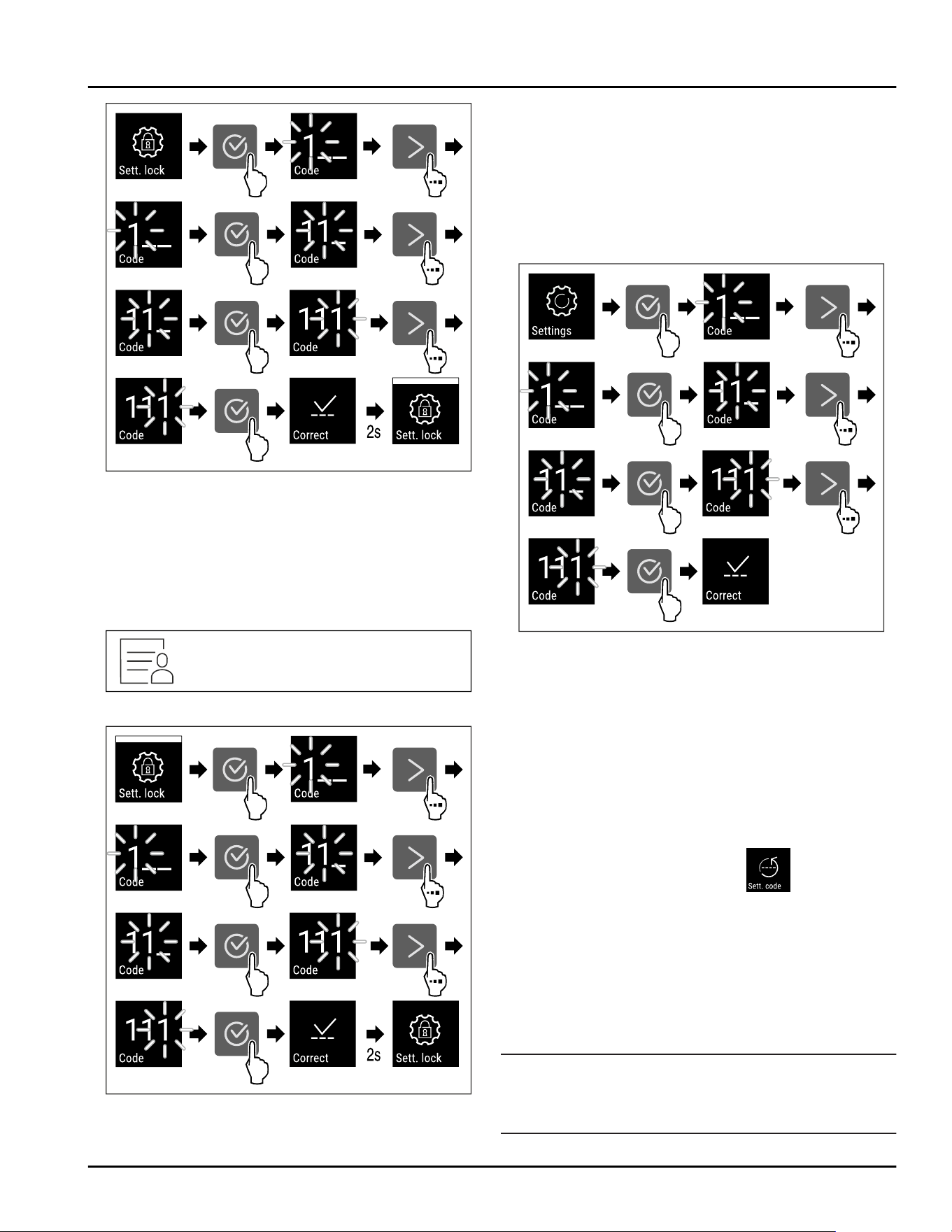
Fig.77
► Carry out action steps according to the illustration.
▷ Settings menu access protection is activated.
Changing the access protection PIN code for the
settings menu
See: (see6.2.6Access codes)
Deactivating the settings menu access protection
Fig.78
Fig.79
► Carry out action steps according to the illustration.
▷
Settings menu access protection is deactivated.
Opening protected settings menu
A PIN code must be entered to open the settings menu
if the access security is enabled. Access security is
enabled automatically as soon as you exit the settings
menu.
► Tap navigation arrow repeatedly until corresponding
function is displayed.
Fig.80
► Carry out action steps according to the illustration.
▷ The PIN code is correct.
▷ The settings menu opens.
6.2.6 Access codes
Various settings are possible.
Application:
-
Changing the settings code.
-
Resetting the settings code.
Settings menu access protection
Changing the settings code
This setting allows the settings code for settings menu
access protection to be changed.
The setting is made in 3 stages:
- Entering the old settings code
- Entering the new settings code
- Confirming the new settings code
Note
► In the following example, the default factory-set
settings code111 is changed.
► The new settings code is:234
Use
26 * Depending on model and options
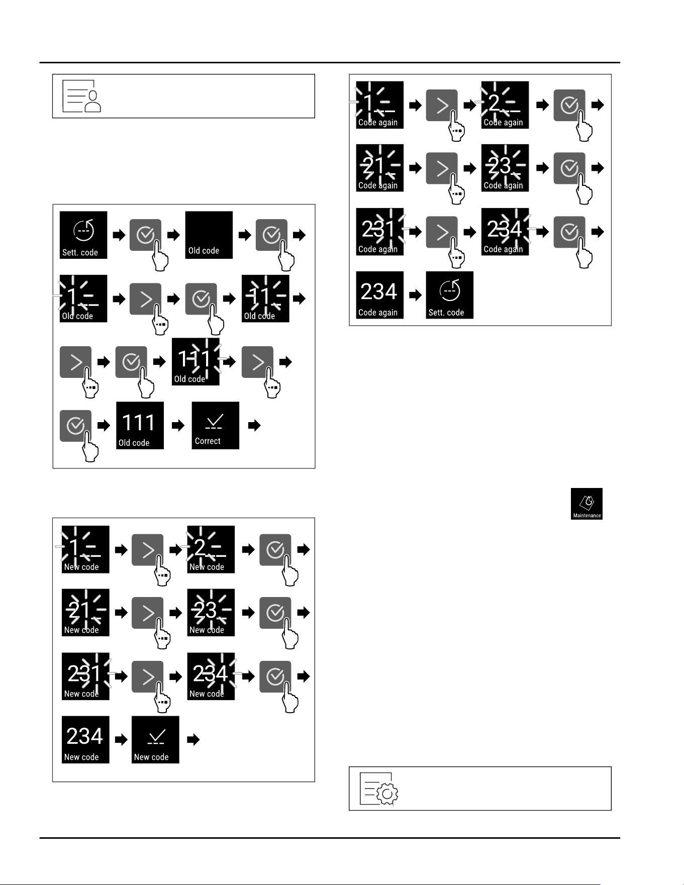
Fig.81
The access protection for the settings menu must
be active. (see 6.2.5 Settings menu access protec‐
tion )
► Press the navigation arrow repeatedly until the
corresponding function is displayed.
Fig.82
► Carry out action steps according to the illustration.
▷ Entry of the old settings code successful.
Fig.83
► Carry out action steps according to the illustration.
▷ Entry of the new settings code successful.
Fig.84
► Carry out action steps according to the illustration.
▷ Confirmation of the new settings code.
▷ The settings code has been changed.
Resetting the settings code
The settings code for the settings menu access protec‐
tion has been forgotten or is not known.
► Reset the appliance to factory settings
(see6.2.25 Resetting to factory settings ) .
▷ The appliance is reset to the original settings.
▷ The factory-set settings code is:111
6.2.7 Maintenance interval reminder
Setting for the time interval after which a maintenance
reminder is issued.
The following values can be set:
-
7 days
-
14 days
-
30 days
-
60 days
-
90 days
-
180 days
-
360 days
-
720 days
-
1080 days
-
Off
Setting maintenance interval reminder
The following steps describe how the maintenance
interval is set.
Use
* Depending on model and options 27
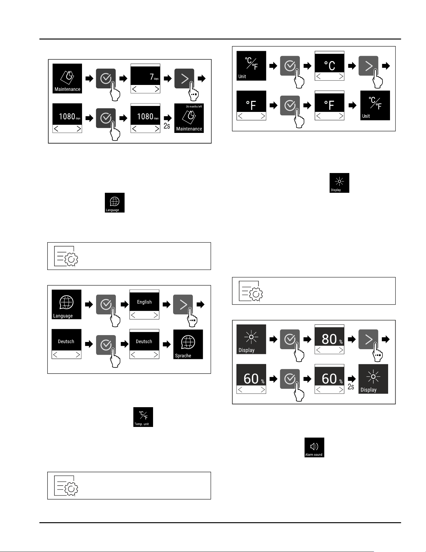
Fig.85
Fig.86
► Carry out action steps according to the illustration.
▷ The time interval, after which the maintenance
reminder is issued, is set.
▷ The remaining time is displayed.
6.2.8 Language
This setting allows the display language to be set.
Setting the language
Fig. 87
Fig.88
► Carry out action steps according to the illustration.
▷ The selected language is set.
6.2.9 Temperature unit
Use this function to set the temperature unit. You can
set the temperature unit in either degrees Celsius or
degrees Fahrenheit.
Setting the temperature unit
Fig.89
Fig. 90 Example illustration: Switching between
degrees Celsius or degrees Fahrenheit.
► Carry out action steps according to the illustration.
▷ Temperature unit is set.
6.2.10 Display Brightness
Use this function to set the brightness of the display
gradually.
You can set the following brightness levels:
-
40%
-
60%
-
80%
-
100% (default setting)
Setting the brightness
Fig. 91
Fig. 92 Example illustration: Switching from 80% to 60%.
► Carry out action steps according to the illustration.
▷ Brightness is set.
6.2.11 Alarm Sound
This function enables all alarm sounds, such as the
door alarm, to be switched on and off.
Use
28 * Depending on model and options
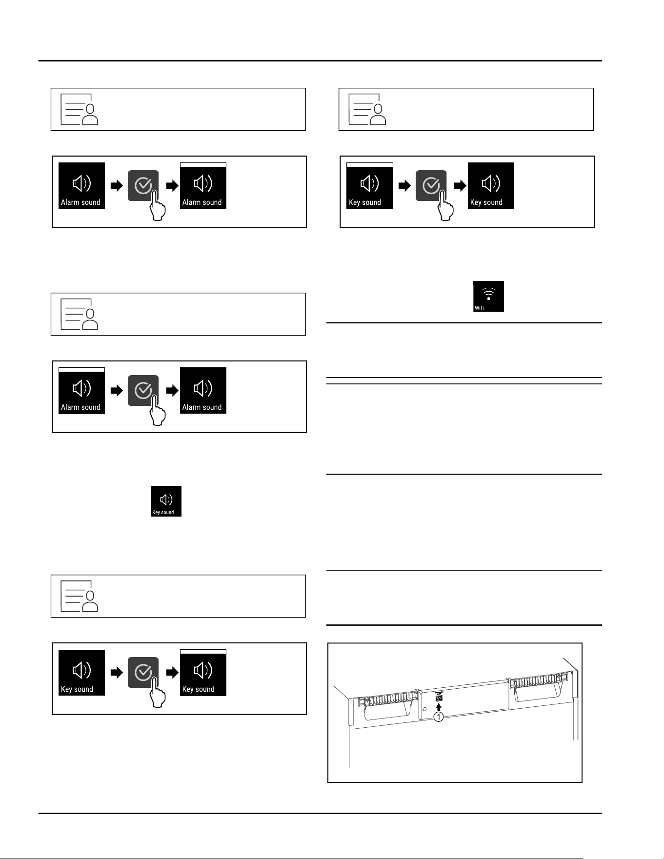
Activating Alarm Sound
Fig. 93
Fig. 94
► Carry out action steps according to the illustration.
▷ Alarm Sound is activated.
Deactivating Alarm Sound
Fig.95
Fig.96
► Carry out action steps according to the illustration.
▷ Alarm Sound is deactivated.
6.2.12 Key Sound
This function makes it possible to switch all confirma‐
tion sounds and the Startsound on and off.
Activating Key Sound
Fig.97
Fig.98
► Carry out action steps according to the illustration.
▷ Key Sound is activated.
Deactivating Key Sound
Fig.99
Fig. 100
► Carry out action steps according to the illustration.
▷ Key Sound is deactivated.
6.2.13 WiFi connection
Note
Liebherr SmartMonitoring Dashboard is not available in
all countries. Check availability via the QR code by
entering your model.
Note
Use of the Liebherr SmartMonitoring Dashboard at
https://smartmonitoring.liebherr.com requires instal‐
lation of a SmartModule and a commercial MyLiebherr
account. When commissioning online you can register
using your login data, or register again and create a
company account.
This setting establishes a wireless connection between
the appliance and the internet. The connection is
controlled via the SmartModule. The appliance can be
integrated via the browser-based Liebherr SmartMoni‐
toring Dashboard and advanced options and custom‐
ized methods relating to control, administration and
monitoring can be used.
Note
Accessories are available from the Liebherr Service
Center. The address for your respective country can be
found on the back of the instructions.
Fig. 101
Use
* Depending on model and options 29
Make sure that the following requirements are fulfilled:
❑
SmartModule Fig. 101(1) is in use.
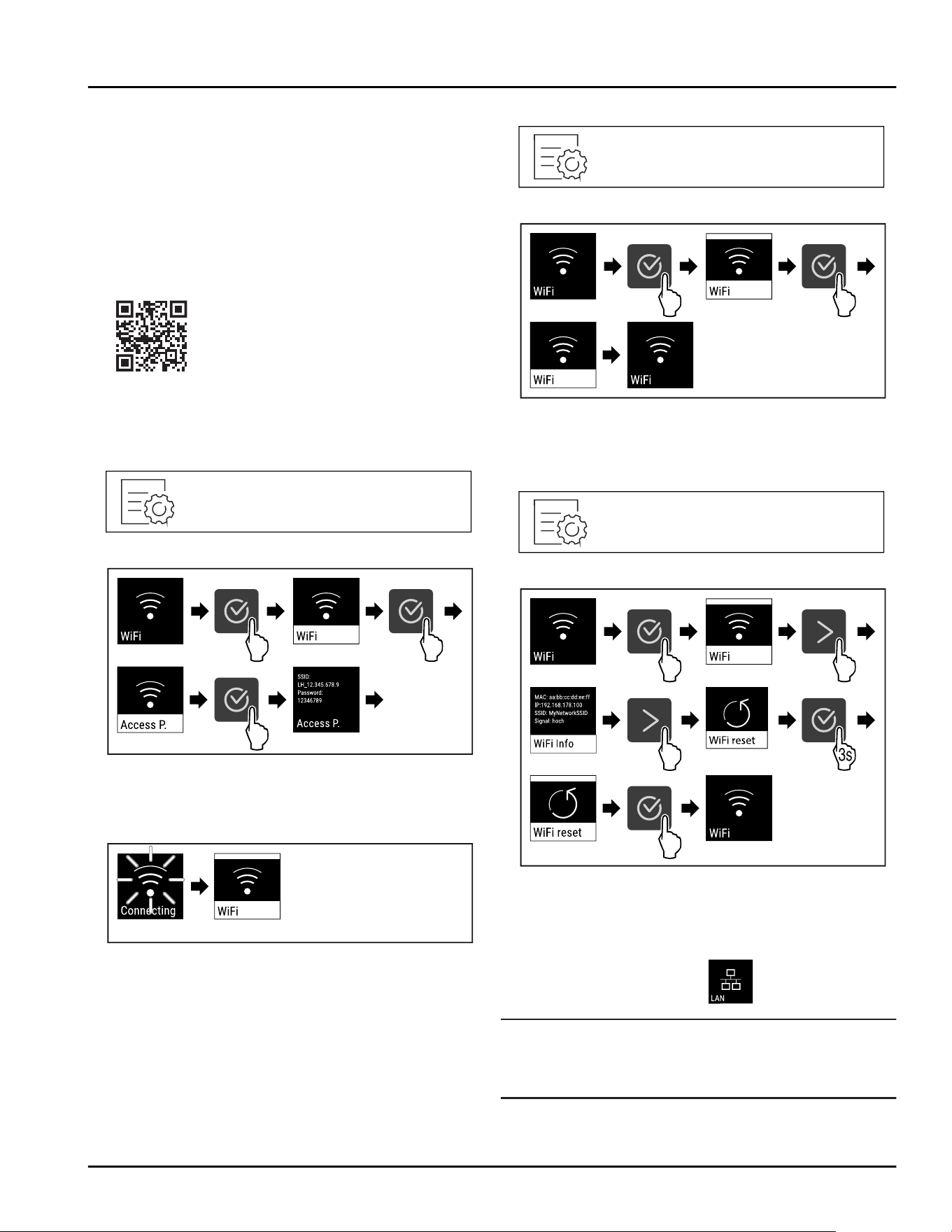
Establishing a connection
You commission and set up your SmartModule online
via the Liebherr SmartMonitoring Dashboard on your
web-enabled device.
On the Liebherr SmartMonitoring Dashboard informa‐
tion is also available about retrofitting the Smart‐
Module.
Fig. 102
► Open the Liebherr SmartMonitoring Dashboard (see
Fig. 102) .
On the fridge or freezer:
Fig. 103
Fig. 104
► Carry out action steps according to the illustration.
► Continue the set-up procedure on your web-enabled
device: Liebherr SmartMonitoring Dashboard
Fig. 105
► Connection is established.
▷ WiFi connecting appears. The symbol flashes.
► Follow the Liebherr SmartMonitoring Dashboard
instructions.
▷ Connection is established.
Disconnecting
Fig. 106
Fig. 107
► Carry out action steps according to the illustration.
▷ There is no connection.
Resetting connection
Fig. 108
Fig. 109
► Carry out action steps according to the illustration.
▷ The WiFi settings are restored to the factory
settings.
6.2.14 LAN connection
Note
Liebherr SmartMonitoring Dashboard is not available in
all countries. Check availability via the QR code by
entering your model.
Use
30 * Depending on model and options
Note
Use of the Liebherr SmartMonitoring Dashboard at
https://smartmonitoring.liebherr.com requires instal‐
lation of a SmartModule and a commercial MyLiebherr
account. When commissioning online you can register
using your login data, or register again and create a
company account.
This setting establishes a wired connection between
the appliance and the internet. The connection is
controlled via the SmartModule. The appliance can be
integrated via the browser-based Liebherr SmartMoni‐
toring Dashboard and advanced options and custom‐
ized methods relating to control, administration and
monitoring can be used.
Note
Accessories are available from the Liebherr Service
Center. The address for your respective country can be
found on the back of the instructions.
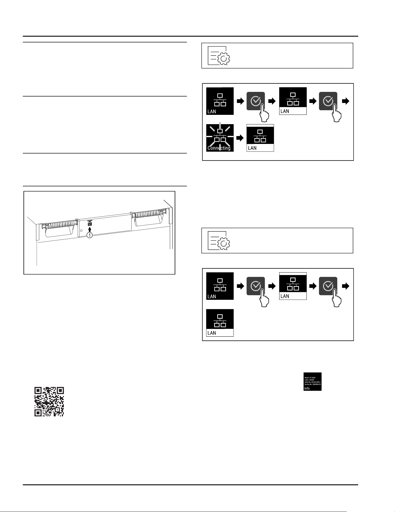
Fig. 110
Make sure that the following requirements are fulfilled:
❑
SmartModule Fig. 110(1) is in use.
❑
A network cable is connected.
❑
The network is connected to the Internet.
Establishing a connection
You commission and set up your SmartModule online
via the Liebherr SmartMonitoring Dashboard on your
web-enabled device.
On the Liebherr SmartMonitoring Dashboard informa‐
tion is also available about retrofitting the Smart‐
Module.
Fig.111
► Open the Liebherr SmartMonitoring Dashboard (see
Fig.111) .
On the fridge or freezer:
Fig.112
Fig.113
► Carry out action steps according to the illustration.
▷ Connection is established: LAN connecting appears.
The symbol flashes.
► Follow the Liebherr SmartMonitoring Dashboard
instructions.
▷ Connection is established.
Disconnecting
Fig. 114
Fig. 115
► Carry out action steps according to the illustration.
▷ There is no connection.
6.2.15 Appliance information
Use this function to display the model name, index,
serial number and service number of your appliance.
You will need the appliance information when you
contact customer service. (see 9.3 Customer Service)
You also use this function to open the expanded menu.
(see3 Functionality of the Touch display)
Use
* Depending on model and options 31
Display appliance information
Fig. 116
Fig.117
► Carry out action steps according to the illustration.
▷ Display shows the appliance information.
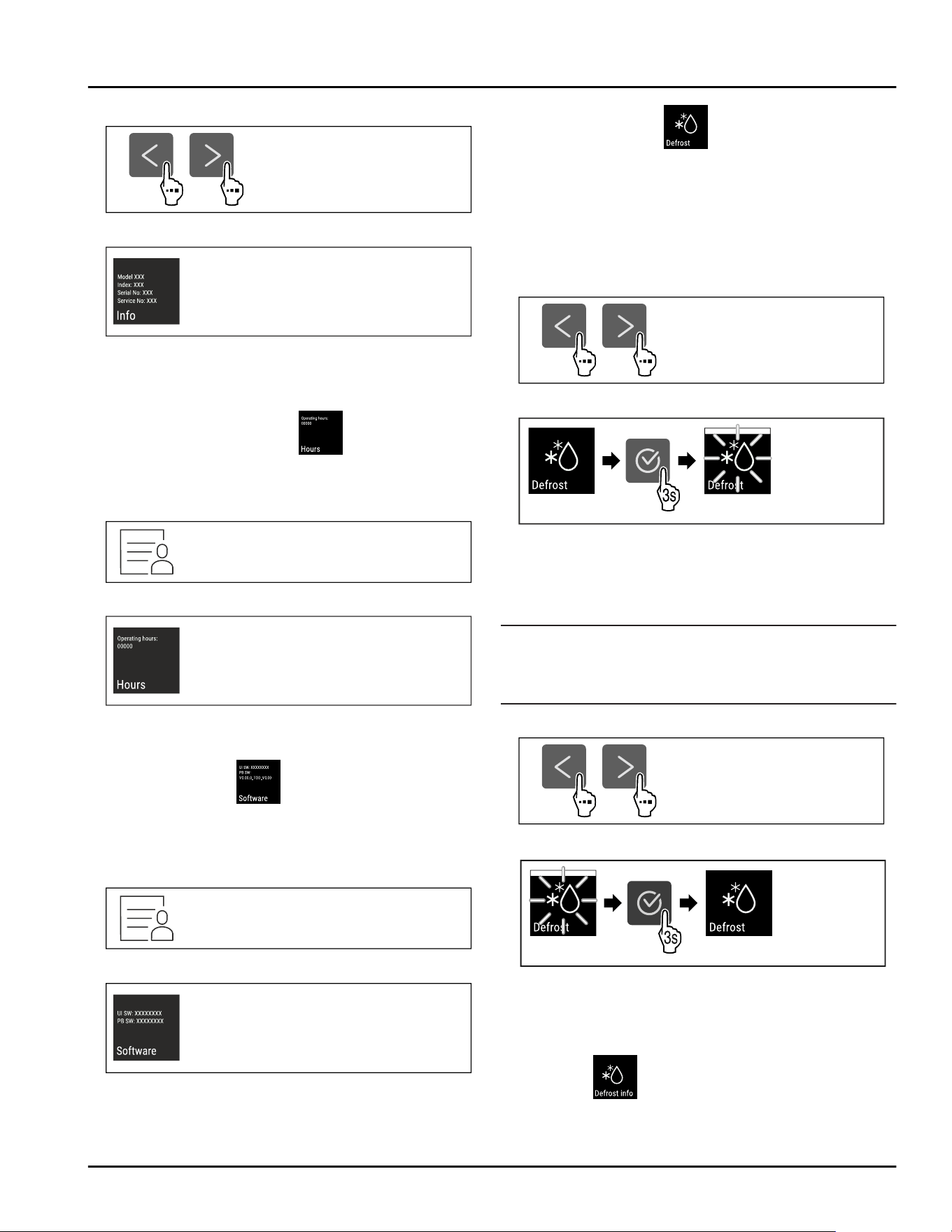
6.2.16 Operating hours
The display shows the appliance operating hours.
Displaying operating hours
Fig. 118
Fig. 119
▷ The operating hours appear.
6.2.17 Software
Use this function to display the software version of
your appliance.
Display software version
Fig.120
Fig.121
► Carry out action steps according to the illustration.
▷ Display indicates the software version.
6.2.18 Defrosting
The appliance defrosts automatically in normal opera‐
tion.
Application:
-
If heavier icing occurs inside the appliance, you can
start the automatic defrosting function manually.
Starting automatic defrost manually
Fig.122
Fig.123
► Carry out action steps according to the illustration.
▷ Automatic defrost has started. After defrost is
complete, the appliance switches back to normal
operation again.
Note
If there is still ice in the interior after several automatic
defrost starts, defrost the appliance manually.
(see8.2 Defrosting the appliance)
Canceling manually started defrost
Fig. 124
Fig.125
► Carry out action steps according to the illustration.
▷ Manually started defrost is canceled. The appliance
switches back to normal operation again.
Defrost info
The display during the automatic defrosting is adjusted
with this setting.
Use
32 * Depending on model and options
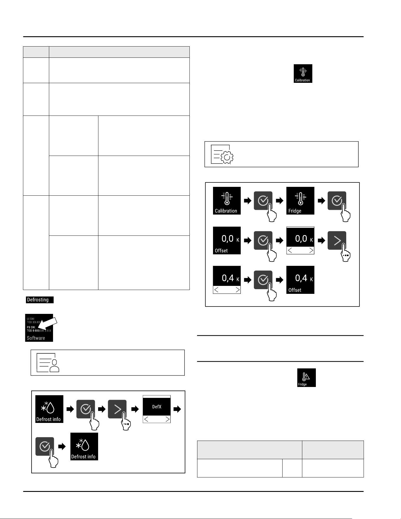
Display Description
Def1 The temperature display is not updated. It
shows the last temperature before automatic
defrost was started.
Def2 The “automatic defrosting” symbol is
displayed on the status display. The temper‐
ature display is continuously updated and
shows the actual temperature.
Def3 As of software
version
PW SW less
than
TOD8-800:
The temperature display is
not updated. It shows the
last temperature before
automatic defrost was
started.
As of software
version
PW SW equal
or more than
TOD8-800:
The temperature display is
continuously updated and
shows the actual tempera‐
ture.
Def4 As of software
version
PW SW less
than
TOD8-800:
The temperature display is
not updated. It shows the
last temperature before
automatic defrost was
started.
As of software
version
PW SW equal
or more than
TOD8-800:
The “automatic defrosting”
note is displayed on the
status display. The tempera‐
ture display is not updated.
It shows the last tempera‐
ture before automatic
defrost was started.
Note for “automatic defrosting” is shown
in the status display
Here, you see the software version
installed on your appliance PW SW:
(see 6.2.17 Software )
Fig. 126
Fig.127
►
Carry out action steps according to the illustration.
▷ The display variant you want is selected.
6.2.19 Sensor calibration
The sensor calibration allows you to offset differences
between the set and the actual temperature. To do so,
determine the actual temperature using a calibrated
measuring gauge.
Setting range: +/- 3 Kelvin in 0.1 Kelvin increments.
Calibrating the sensor
Fig.128
Fig.129
► Carry out action steps according to the illustration.
▷ The sensor is calibrated.
Note
The calibrated temperature is shown on the display
within two hours.
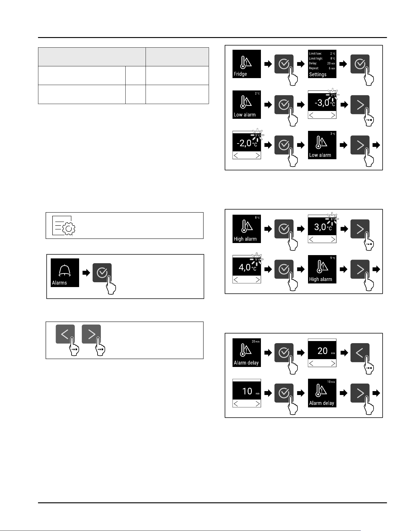
6.2.20 Temperature alarm
Set the temperature alarm with this function. In the
process, define the upper and lower temperature limit
with a differential value to the currently set interior
temperature. The temperature alarm is triggered once
the interior temperature leaves the set temperature
range and any set delay time has expired.
For example
Differential value
to be set
Current interior tempera‐
ture
5°C
41°F
Use
* Depending on model and options 33
For example Differential value
to be set
Lower temperature limit 2°C
36°F
-3°C
27°F
Upper temperature limit 8°C
46°F
+3°C
37°F
You can set the following values:
-
Differential value for lower temperature limit in 0.1
°C( °F) intervals
-
Differential value for upper temperature limit in 0.1
°C( °F) intervals
-
Alarm delay time from 0 to 60 minutes (a setting of
“0” does not mean there is a delay in the tempera‐
ture alarm.)
-
Repetition frequency of the alarm from 0 to 30
minutes after confirming the alarm (setting of “0”
means no repeated alarm after confirming the alarm
relay.)
Setting temperature alarm
Fig.130
Fig.131
► Carry out action steps according to the illustration.
Fig.132
Fig. 133 Example for setting the lower temperature limit
based on a set appliance temperature of 5°C.
► Carry out action steps according to the illustration.
▷ Lower temperature limit has been set.
Fig. 134 Example for setting the lower temperature limit
based on a set appliance temperature of 5°C.
► Carry out action steps according to the illustration.
▷ Upper temperature limit has been set.
Fig.135
► Carry out action steps according to the illustration.
▷ Alarm delay time has been set.
Use
34 * Depending on model and options
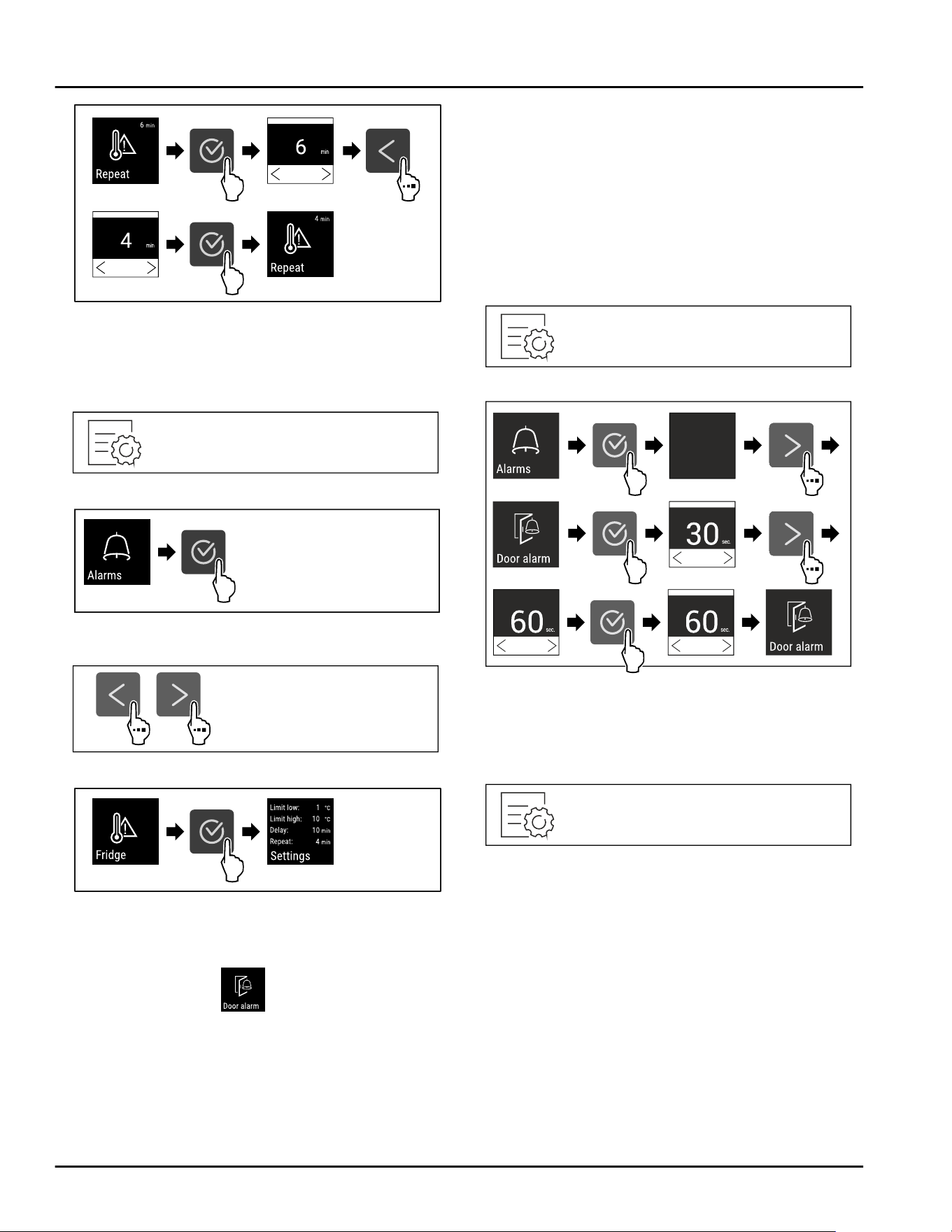
Fig.136
► Carry out action steps according to the illustration.
▷ Alarm repetition interval has been set.
▷ Temperature alarm has been set.
Displaying set temperature alarm values
Fig.137
Fig.138
► Carry out action steps according to the illustration.
Fig. 139
Fig. 140
► Carry out action steps according to the illustration.
▷ Set temperature alarm values are displayed.
6.2.21 Door alarm
Use this function to activate or deactivate the door
alarm. The door alarm sounds if the door is open for
too long. The door alarm is activated upon delivery. You
can set how long to door can remain open until the
door alarm sounds.
You can set the following values:
-
15seconds
-
30seconds
-
60seconds
-
90seconds
-
120seconds
-
150seconds
-
180seconds
-
Off
Setting the door alarm
Fig. 141
Fig. 143 Example illustration: Changing the door alarm from
30 seconds to 60seconds.
► Carry out action steps according to the illustration.
▷ Door alarm is set.
Deactivating door alarm
Fig. 144
Use
* Depending on model and options 35
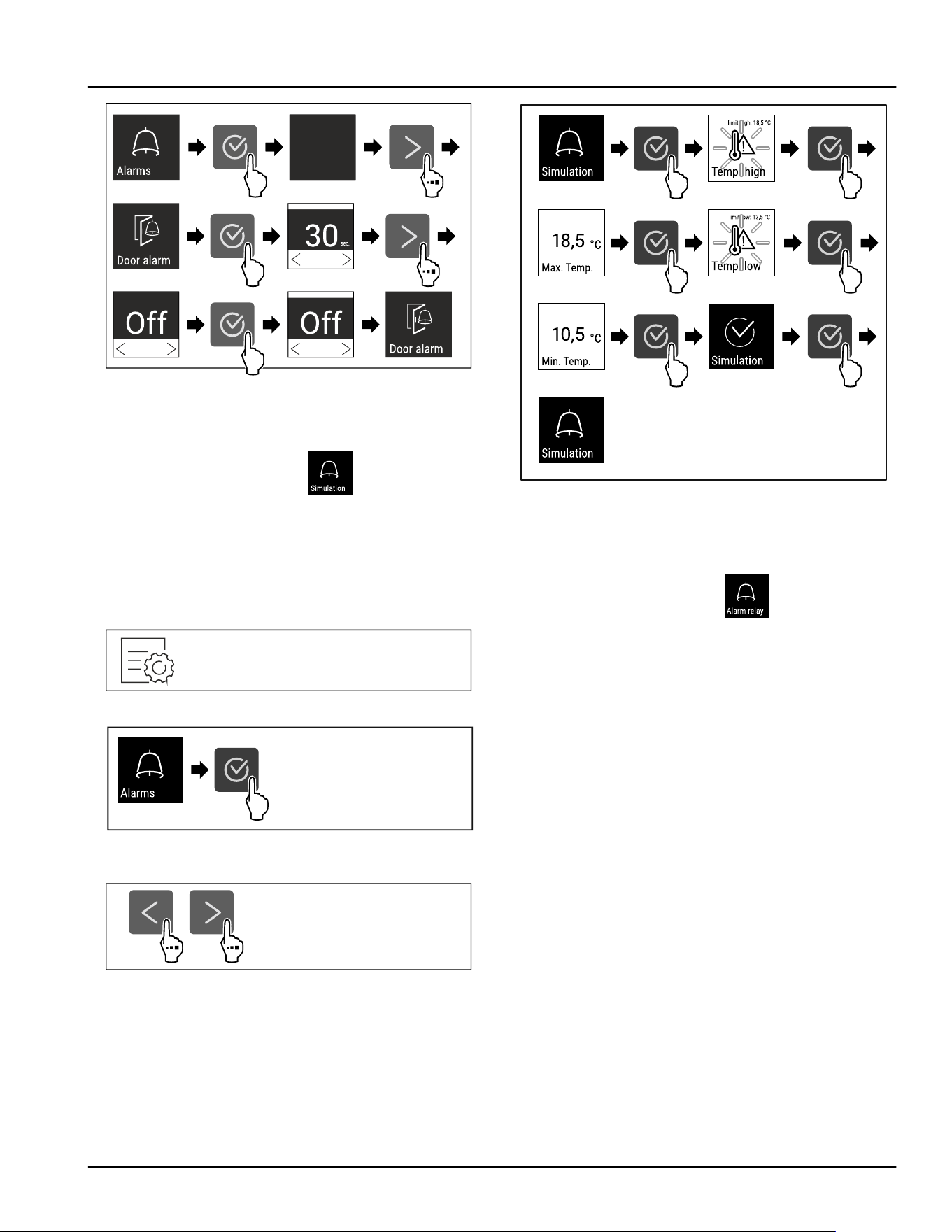
Fig. 145
► Carry out action steps according to the illustration.
▷ Door alarm is deactivated.
6.2.22 Alarm simulation
This function enables you to simulate a temperature
alarm in the appliance, e.g. to check whether one of
the safety devices triggers correctly. The safety device
is connected to the potential-free alarm output.
(see 7.3 Interfaces)
Starting the alarm simulation
Fig. 146
Fig. 147
► Carry out action steps according to the illustration.
Fig. 148
Fig. 149
► Carry out action steps according to the illustration.
▷ The simulation has been performed.
▷ Connected safety devices should have triggered.
6.2.23 Alarm forwarding
This function enables you to set to have one or several
alarms to be forwarded to an external alarm receiver.
Here, the alarm receiver is connected to the applian‐
ce’s potential-free alarm output. (see 7.3 Interfaces)
You can select from the following settings:
-
Alarm type:
•
Door alarm
•
Temperature alarm
•
Door alarm and temperature alarm
•
All
-
Confirm:
•
Yes: The alarm is confirmed on the appliance and
the externally connected receiver.
•
No: The alarm is confirmed on the appliance and
remains active on the receiver until the error is
remedied.
-
Update (only visible if you have selected “Yes” when
you confirmed):
•
Yes: Alarm repeats.
Temperature alarm depending on the set time
(see6.2.20 Temperature alarm )
(If you set the delay time of the alarm to “0”,
there will be no alarm repetition at the alarm
relay either.)
Door alarm after 1 or 4 minutes*
(see6.2.21Door alarm )
•
No: Alarm permanently confirmed.
Use
36 * Depending on model and options
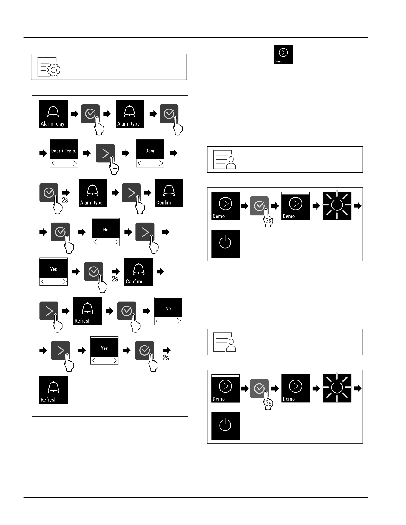
Activating alarm forwarding
Fig. 150
Fig. 151
► Carry out action steps according to the illustration.
▷ Alarm forwarding is set.
6.2.24 Demo mode
Demo mode is a special feature for dealers who want
to demonstrate appliance features. If you activate
demo mode, all refrigeration functions are deactivated.
If you switch on your appliance and a “D” appears on
the status display, demo mode is already activated.
If you activate and then deactivate demo mode, the
appliance will be reset to factory defaults.
(see6.2.25 Resetting to factory settings )
Activating demo mode
Fig. 152
Fig. 153
► Carry out action steps according to the illustration.
▷ Demo mode is activated.
▷ Appliance is switched off.
► Switch on the appliance. (see 4.16 Switching on the
appliance (first use))
▷ “D” appears in the status display.
Deactivating demo mode
Fig. 154
Fig. 155
► Carry out action steps according to the illustration.
▷ Demo mode is deactivated.
▷ Appliance is switched off.
► Switch on the appliance. (see 4.16 Switching on the
appliance (first use))
Use
* Depending on model and options 37
▷ Appliance is reset to factory settings.
6.2.25 Resetting to factory settings
Use this function to reset all settings to factory
settings. All settings you have made so far are reset to
their original settings.
Performing a reset
Fig. 156
Fig. 157
► Carry out action steps according to the illustration.
▷ Appliance is reset.
▷ Appliance is switched off.
► Restart the appliance. (see 4.16 Switching on the
appliance (first use))
6.3 Messages
6.3.1 Warnings
Warnings are issued by means of an audio signal and
visually via a symbol on the display. The signal gets
louder until the warning is acknowledged.
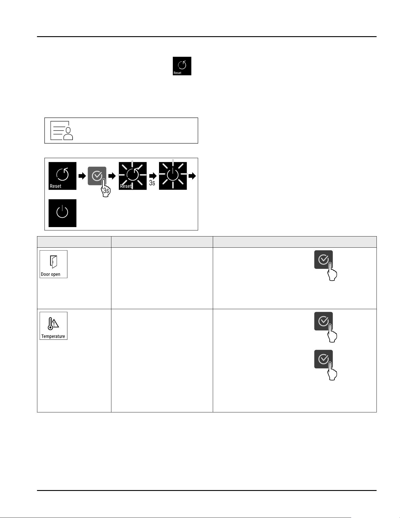
Message
Cause Remedy
Door open
The message appears if the
door is open for too long.
Close the door.
Press the confirmation button.
Alarm is ended.
Note
You can set how long it takes
for this message to appear
(see6.2.21Door alarm ) .
Temperature alarm
This message appears if the
temperature does not match the
set temperature. Reasons for
the differences in temperature
can be:
⁃ Warm items for refrigeration
have been placed inside.
⁃ Too much warm room air
flowed in when rearranging and
removing refrigerated products.
⁃ The power was cut off for a
prolonged period.
Press the confirmation button.
The warmest temperature is
displayed.
Press the confirmation button.
The current temperature
flashes and the display alter‐
nates with the temperature
alarm symbol until the set
temperature is reached.
Check the quality of the chilled
goods.
Use
38 * Depending on model and options
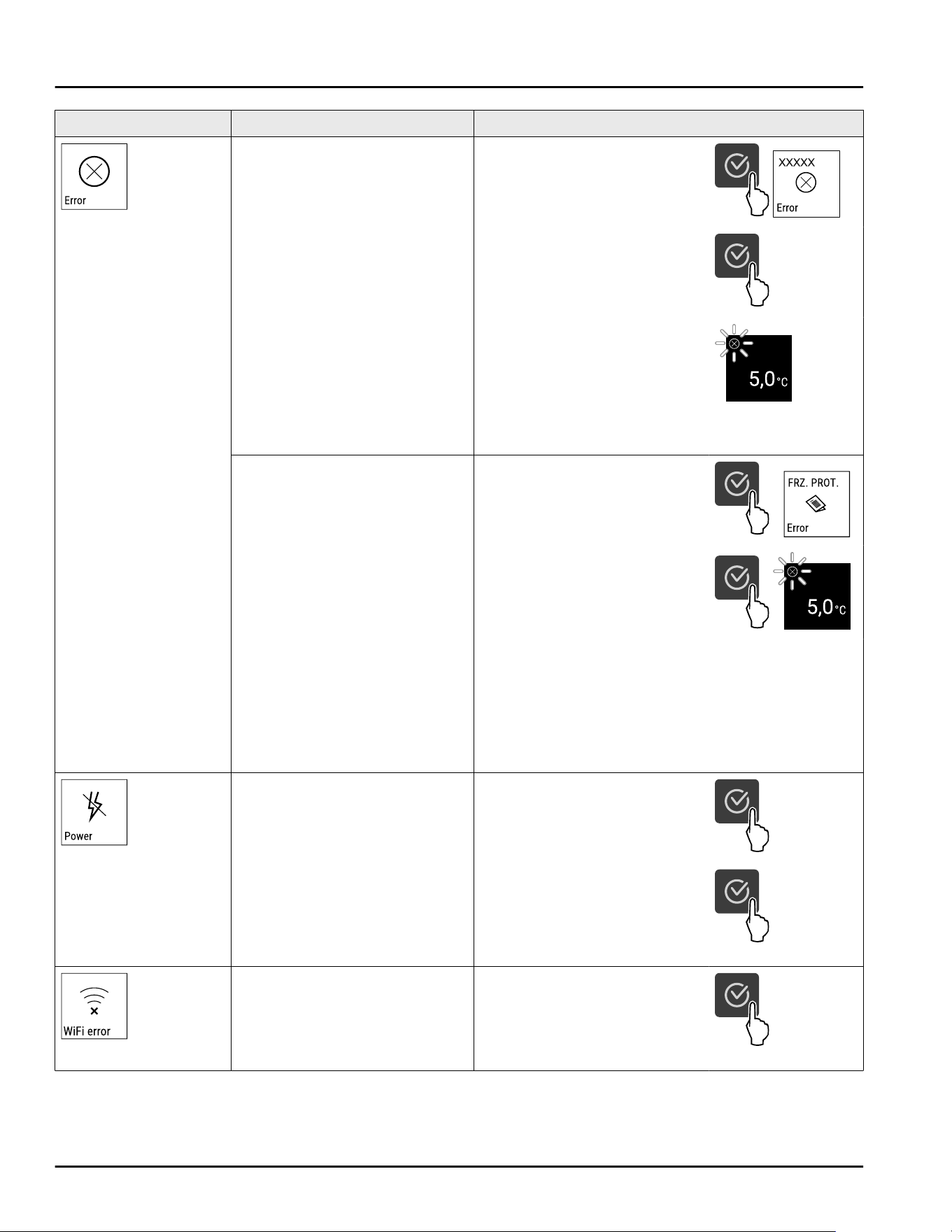
Message Cause Remedy
Error
The appliance is defective, there
is an appliance error or an appli‐
ance module indicates an error.
Relocate the chilled goods.
Press the confirmation button.
Error code is displayed.
Press the confirmation button.
If present, another error code is
displayed.
or
Status screen with flashing
error symbol is displayed.
Pressing the navigation
buttons displays error code(s)
again.
Note error code(s) and contact
customer service.
Message indicates that the
freezer protection mode is
active (e.g. due to frequent door
openings or loading with goods).
Press the confirmation button.
FRZ.PROT is displayed.
Press the confirmation button.
Status screen with flashing
error symbol is displayed
Pressing the navigation buttons displays error code
again.
The appliance automatically switches to normal
operating mode after a few hours and the message
disappears. If the message is displayed repeatedly
and the causes listed do not apply, contact customer
service. (see 9.3 Customer Service)
Power failure
The message appears after an
interruption in the power supply
if the temperature is above the
alarm limit when the power
returns.
Press the confirmation button.
The warmest temperature is
displayed.
Press the confirmation button.
Alarm is ended and the current
temperature is displayed.
Check the quality of the chilled
goods.
WLAN error
WLAN connection is interrupted. Check the connection.
Press the confirmation button.
Alarm is ended.
Use
* Depending on model and options 39
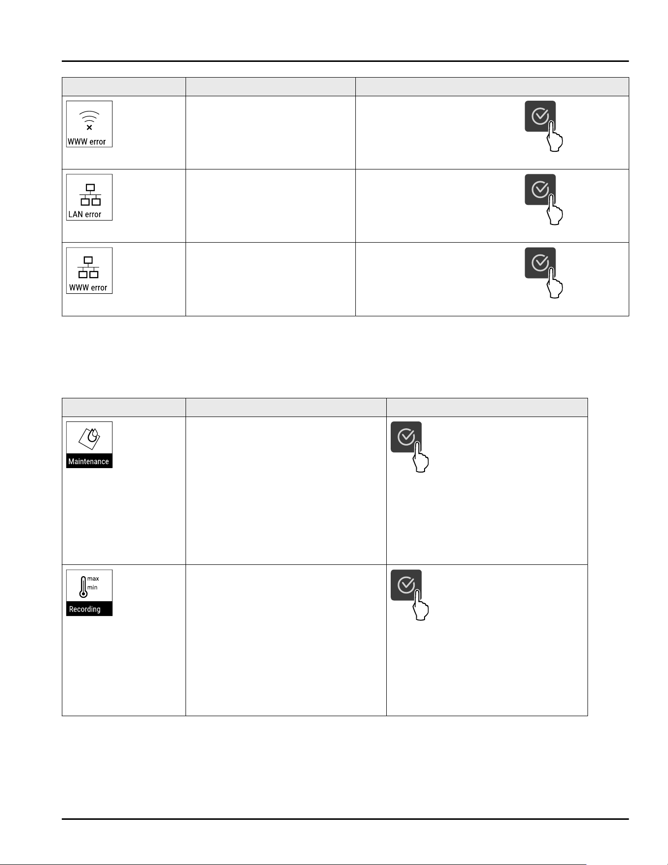
Message Cause Remedy
WLAN WWW error
The message appears if there is
no Internet connection via
WLAN.
Check the connection.
Press the confirmation button.
Alarm is ended.
LAN error
LAN connection is interrupted. Check the connection and
network cable.
Press the confirmation button.
Alarm is ended.
LAN WWW error
The message appears if there is
no Internet connection via LAN.
Check the connection.
Press the confirmation button.
Alarm is ended.
6.3.2 Reminders
Reminders appear when you are prompted to take
action. They are issued by means of an audio signal
and visually via a symbol on the display. Acknowledge
the message by pressing the confirmation button.
Message Cause Remedy
Maintenance reminder
The message appears when the timer
for the set maintenance interval has
expired.
Press the confirmation button.
Alarm is ended.
Note
The maintenance interval can be set
(see 6.2.7 Maintenance interval
reminder ) .
Logging reminder
This message appears when the
temperature logging memory (999
hours) is full.
Press the confirmation button.
Alarm is ended.
The oldest data is overwritten.
Note
The temperature logging can be reset
(see6.2.4 Temperature recording ) .
7 Equipment
7.1 Safety lock
The lock in the appliance door is equipped with a
safety mechanism.
Equipment
40 * Depending on model and options
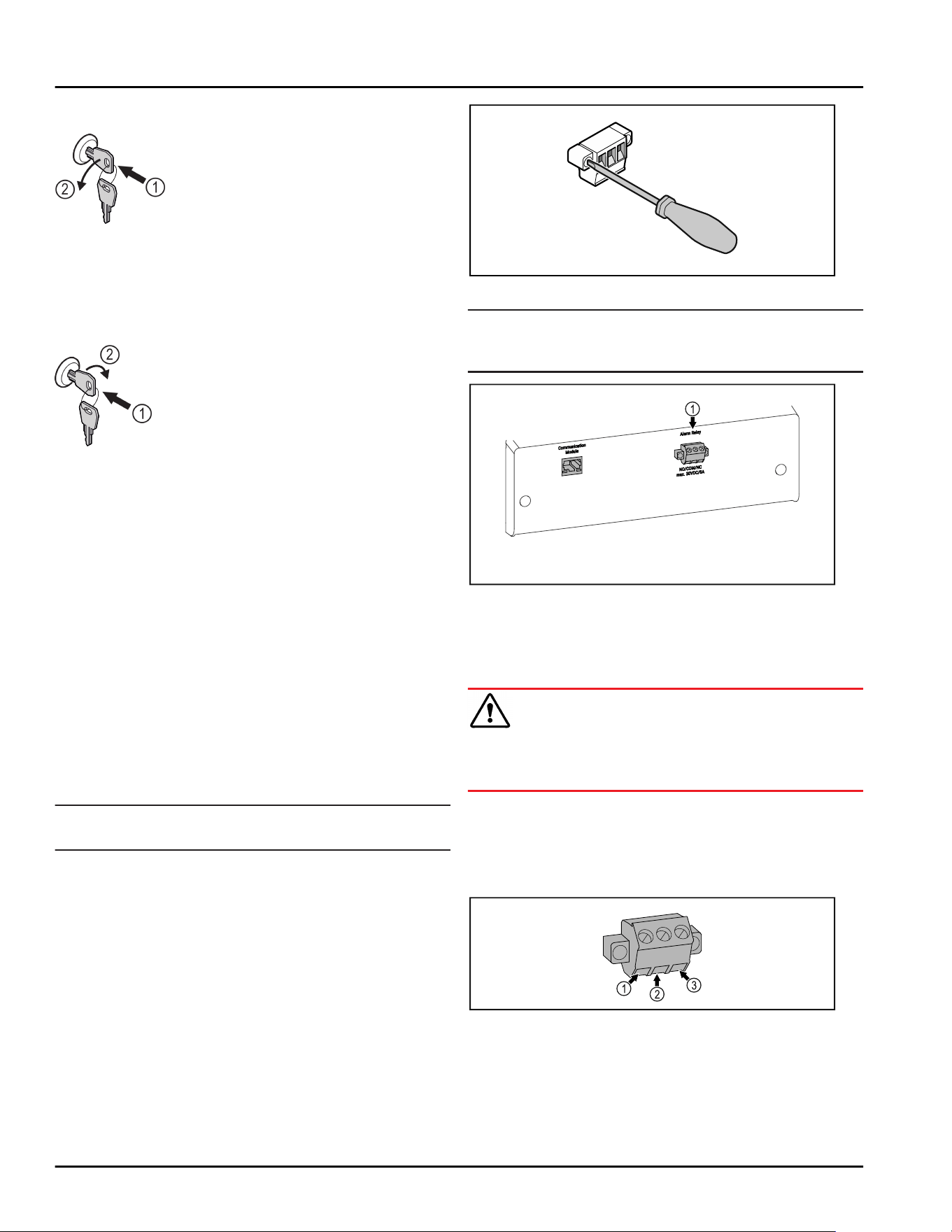
7.1.1 Locking appliance
Fig. 158 Example illustration
► Insert key.
► Turn key anticlockwise by 90°.
▷ The appliance is locked.
7.1.2 Unlocking appliance
Fig. 159 Example illustration
► Insert key Fig. 159(1).
► Turn key clockwise by 90° Fig. 159(2).
▷ The appliance is unlocked.
7.2 Sensors
The appliance can be equipped with the following
sensors for temperature monitoring:
-
Safety thermostat sensor
-
C sensor
7.2.1 Safety thermostat sensor
The safety thermostat sensor monitors the tempera‐
ture drop and thus protects against excessively low
temperatures (Freeze Protect). If the temperature drops
below the threshold value, the appliance regulates the
temperature automatically. The error message FRZ.
PROT (Freeze Protect) (see 6.3Messages) appears.
Note
Do not cover the safety thermostat sensor.
7.2.2 C sensor (control sensor)
The C sensor is permanently installed and regulates
the interior temperature of the appliance. You can cali‐
brate the C sensor if necessary. (see 6.2.19 Sensor cali‐
bration )
7.3 Interfaces
There are various connection options on the back of
the appliance.
Fig. 160
Note
Screws secure the plugs. To enable disconnection of
the plugs, loosen the screws on the left and right.
Fig. 161
(1)
Potential-free alarm
output
7.3.1 Potential-free alarm output
WARNING
Risk of injury due to electric shock!
► The appliance may only be connected to an external
alarm device by trained specialist personnel.
These three contacts can be used to connect a visual
or an acoustic alarm device. The connection is
designed for a maximum of 30 V (DC) - 8 A from a
safety low voltage source SELV (minimum current
150mA).
Equipment
* Depending on model and options 41
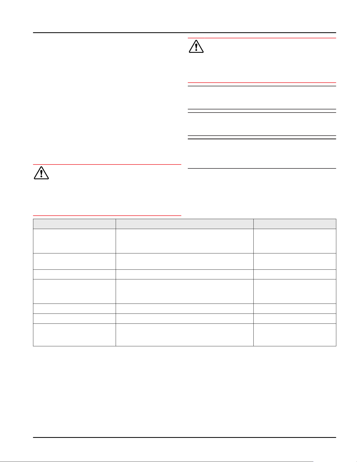
Fig. 162
(1) NO (normally open)
Connection for indi‐
cator lamp, which is
active in normal
operation or when
the appliance is
switched off.
(3) NC (normally closed)
Connection for alarm
lamp or audible
alarms, which is active
when an alarm is trig‐
gered or lack of power
supply.
(2) COM (common)
External voltage
source
8 Maintenance
8.1 Maintenance schedule
Maintenance work is to be performed at regular inter‐
vals to ensure proper appliance function.
CAUTION
Danger of injury and damage due to unprofessional
maintenance work!
Personal injury and material damage.
► Maintenance work may only be performed by trained
specialist personnel.
WARNING
Short-circuit hazard due to live parts!
Electric shock or damage to the electronics.
► Switch off the appliance.
► Pull out mains plug or switch off fuse.
Note
A maintenance reminder function can be activated.
(see 6.2.7 Maintenance interval reminder )
Note
We recommend creating a maintenance log in which all
work (repairs, checks) performed is documented.
Note
Liebherr recommends yearly maintenance. For an indi‐
vidual offer, please contact Customer Service
(see 9.3 Customer Service) .
Component Activity Maintenance interval
Sheet metal parts Check for damage and corrosion.
Replace damaged parts: (see 9.3 Customer
Service)
Yearly
Door, hinges Check alignment (see 4.14 Aligning the door) ,
ease of movement, and tight fit.
Yearly
Lock, door handle * Check for ease of movement and tight fit. Yearly
Door seal Check for damage, wear, and tight fit.
A replacement door gasket is available via
Customer Service (see 9.3 Customer Service) .
Yearly
Sensor Calibrate sensor. (see 6.2.19 Sensor calibration ) Yearly
Sensor feedthrough Check that the sealing compound is intact. Yearly
Surfaces Cleaning (see 8.3Cleaning the appliance) Recommendation: monthly or
as required/specified at
installation location
Maintenance
42 * Depending on model and options

Component Activity Maintenance interval
Surfaces Disinfection
Liebherr has tested the following disinfectants:
Dismozon pur 1 % Lösung (Bode Chemie), Suma
Quicksan (Diversey), Incidin Extra N (Ecolab
Healthcare), Acrylan (Antiseptica chem.-pharm.
Produkte), Buraton 10 F (Schülke und Mayr),
Frankocid N (Franken Chemie), Apesin DSR 50
(Tana), Nüscosept Spray (Dr. Nüsken), Melsept SF
(B. Braun Melsungen), Kohrsolin (Bode Chemie),
Neoquat S (Dr. Weigert), Indicin Rapid (Ecolab
Healthcare), Bacillocid Spezial (Bode Chemie),
Neoform K Spray (Dr. Weigert), Apesin Desinf.
Spray (Tana), Nüscosept 100 (Dr. Nüsken), Anti‐
sept T (Fink Tec), Apesin AP 100 0,50% Lösung
(Tana), Perform Pulver 2% Lösung (Schülke und
Mayr)
Observe the operating instructions of the respec‐
tive manufacturer. If disinfectants other than
those stated are used, test them on a less
exposed area first.
Recommendation: monthly or
as required/specified at
installation location
Installation location, appli‐
ance
Decontamination
The appliance is suitable for room decontamina‐
tion with hydrogen peroxide H
2
O
2
.
In this context, the values of the following appli‐
cation specifications must not be exceeded:
Concentration: maximum 250 ppm.
Humidity: maximum 85%.
Maximum permissible room temperature as per
climate class. (see1.4 Range of appliance use)
Recommendation: as
required/specified at instal‐
lation location, maximum 2x
per year
Fan air slots Cleaning (see 8.3.3 Cleaning fan cover) Yearly
Alarm relay
Power cable Check for damage. Yearly
or
if there is a change of loca‐
tion
Tilt angle Check for proper function and tight fit. Yearly
or
if there is a change of loca‐
tion
Adjusting feet/castors Check for proper function, damage, and tight fit.
Replace damaged parts. (see 9.3 Customer
Service)
Yearly
Defrost water collection tray Check the fill level of the defrost water collection
tray and empty if necessary.
Regular visual inspection
Maintenance
* Depending on model and options 43
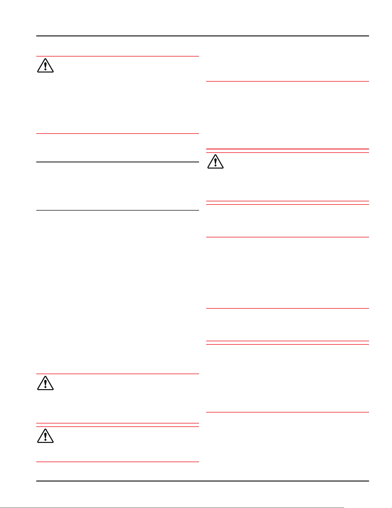
8.2 Defrosting the appliance
WARNING
Appliance incorrectly defrosted!
Injuries and damage.
► Do not use mechanical devices or other means to
accelerate the defrosting process, other than those
recommended by the manufacturer.
► Do not use any electrical heating or steam cleaning
equipment, naked flames or defrosting sprays.
► Do not remove ice with sharp objects.
Defrosting is performed automatically. Defrost water
drips into the defrost water collection tray and must be
emptied at regular intervals.
Note
To avoid having to empty the defrost water collection
tray frequently, you can place a container under the
drain opening in the tray.
The defrost water collection tray may only be inserted
on the lowest support rib.
To maintain the functionality of the appliance, we
recommend defrosting it when there is a high buildup
of ice. Icing in the interior is determined by the location
(e.g. high humidity), settings on the appliance and
incorrect user behavior.
If the automatic defrost cycle is not sufficient:
► Start the automatic defrost manually.
(see 6.2.18 Defrosting )
If the problem persists, defrost the appliance manually:
► Switch off appliance. (see 6.2.2 Switching appliance
on and off )
► Disconnect power plug.
► Store refrigerated items elsewhere.
► Leave the appliance door open during defrosting
process.
► Pull out the defrost water collection tray at the front,
empty it and clean the appliance.
8.3 Cleaning the appliance
8.3.1 Preparing
WARNING
Short-circuit hazard due to live parts!
Electric shock or damage to the electronics.
► Switch off the appliance.
► Pull out mains plug or switch off fuse.
WARNING
Danger of fire
► Do not damage the refrigerant circuit.
► Empty the appliance.
►
Pull out the power plug.
► Observe the notes on appliance transport.
(see 4.3 Transporting the appliance)
8.3.2 Cleaning the housing
NOTICE
Improper cleaning!
Damage to the appliance.
► Only use soft cleaning cloths and ph-neutral all-
purpose cleaners.
► Do not use steel wool or sponges that scour or
scratch.
► Do not use caustic or abrasive cleaning materials or
those containing sand, chloride, or acids.
WARNING
Risk of injury or damage due to hot steam.
Hot steam can cause scalding/burns and damage to
surfaces.
► Do not use steam cleaners.
NOTICE
Risk of damage due to short circuit.
► When cleaning the appliance, make sure no water
gets into the electrical components.
► Wipe the housing down with soft, clean cloth. If very
dirty, use lukewarm water with a neutral cleaner.
Glass surfaces can also be cleaned with glass
cleaner.
► Clean the condenser coil every year. If the condenser
coil is not cleaned, this significantly reduces the
efficiency of the appliance.
8.3.3 Cleaning fan cover
NOTICE
Risk of damage due to short circuit.
► When cleaning the appliance, make sure no water
gets into the electrical components.
NOTICE
Improper cleaning!
Damage to the appliance.
► Only use soft cleaning cloths and ph-neutral all-
purpose cleaners.
► Do not use steel wool or sponges that scour or
scratch.
► Do not use caustic or abrasive cleaning materials or
those containing sand, chloride, or acids.
Maintenance
44 * Depending on model and options
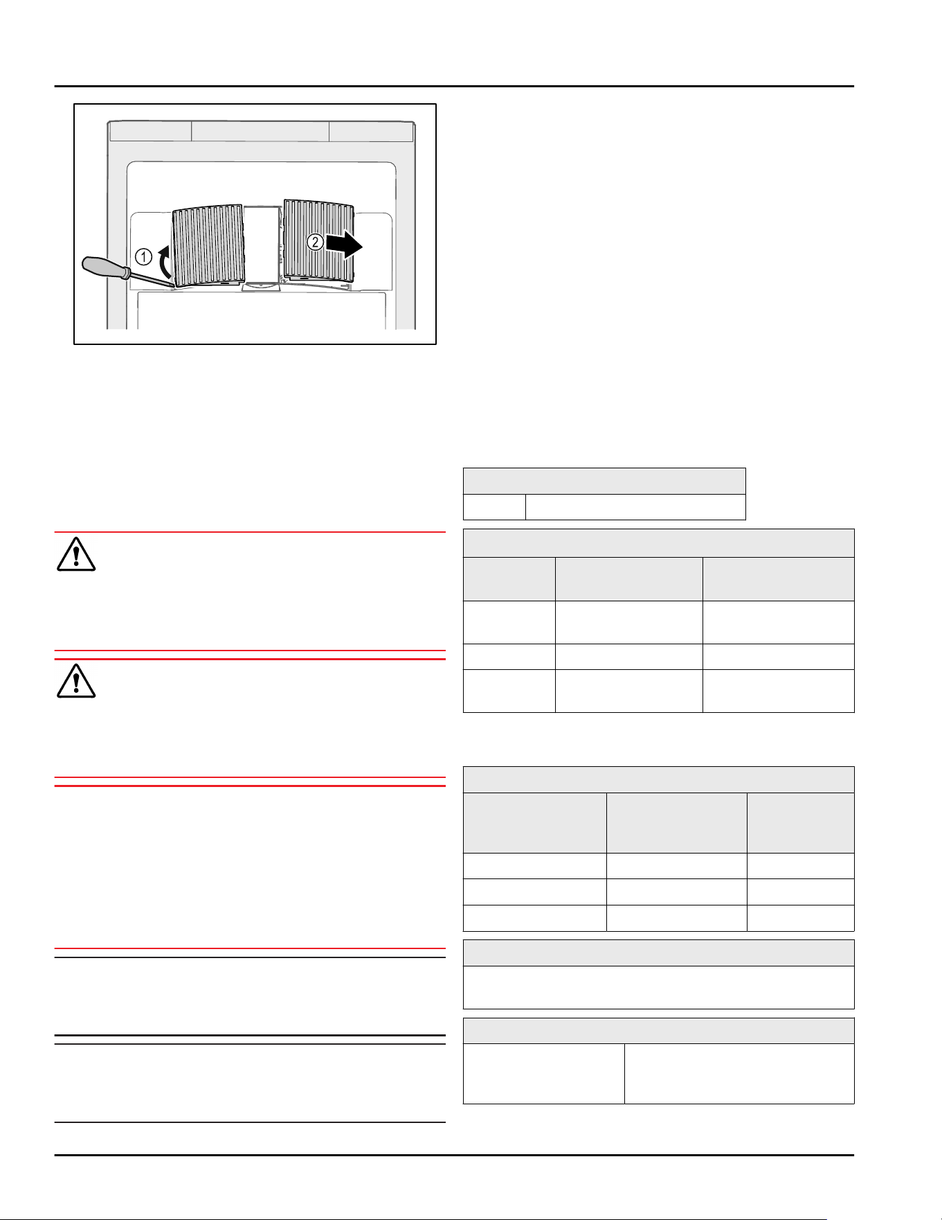
Fig. 163
► Carefully lever out fan covers from the side Fig. 163(1)
and remove towards the front Fig. 163(2).
► Rinse the air slots of the fan covers under running
water. If very dirty, use lukewarm water with a
neutral cleaner.
► Leave fan covers to air-dry completely.
► Reattach fan covers to the appliance.
8.3.4 Cleaning the interior
WARNING
Short-circuit hazard due to live parts!
Electric shock or damage to the electronics.
► Switch off the appliance.
► Pull out mains plug or switch off fuse.
WARNING
Risk of injury or damage due to hot steam.
Hot steam can cause scalding/burns and damage to
surfaces.
► Do not use steam cleaners.
NOTICE
Improper cleaning!
Damage to the appliance.
► Only use soft cleaning cloths and ph-neutral all-
purpose cleaners.
► Do not use steel wool or sponges that scour or
scratch.
► Do not use caustic or abrasive cleaning materials or
those containing sand, chloride, or acids.
Note
► Defrost water drain (see 1.2 Overview of appliance
and equipment) : Remove deposits using a thin
object (e.g. a cotton bud).
Note
Do not damage or remove the type plate on the inside
of the appliance. The type plate is important for
Customer Service. (see 9.3 Customer Service)
► Open the door.
► Empty the appliance.
► Clean the interior and equipment parts with luke‐
warm water and a little dish detergent. Do not use
any gritty or acidic cleaning agent or any chemical
solvent.
8.3.5 After cleaning
► Wipe the appliance and equipment parts dry.
► Connect and switch on appliance.
When the temperature is sufficiently cold:
► Place in items for refrigeration.
► Clean regularly.
► Clean the refrigeration machine with heat exchanger
and remove dust from it once a year.
9 Customer support
9.1 Technical data
Temperature range
Cooling +3°C(38°F) to +16°C(60°F)
Maximum load per shelf
A)
Appliance
width
600mm(23 1/2in) 750mm(29 7/16in)
Grid
shelves
45 kg(99.21lb) 60 kg(132lb)
Glass shelf 40 kg(88.18lb) 40 kg(88.18lb)
Drawer
(freezers)
15 kg(33.07lb) 15 kg(33.07lb)
A)
Heavier loads may result in a slight bending of the
shelves.
Maximum total load and net weight
Model
(see 4.2 Appliance
dimensions)
Maximum total
load
Net weight
SRF.. 3501 180 kg(397lb) 60 kg(132lb)
SRFfg 4001 225 kg(496lb) 70 kg(154lb)
SRF.. 5501 300 kg(661lb) 80 kg(176lb)
Net capacity
See net capacity on the type plate. (see 1.2 Overview
of appliance and equipment)
Setup conditions
Degrees of pollution
(surrounding the
appliance)
PD2
Customer support
* Depending on model and options 45
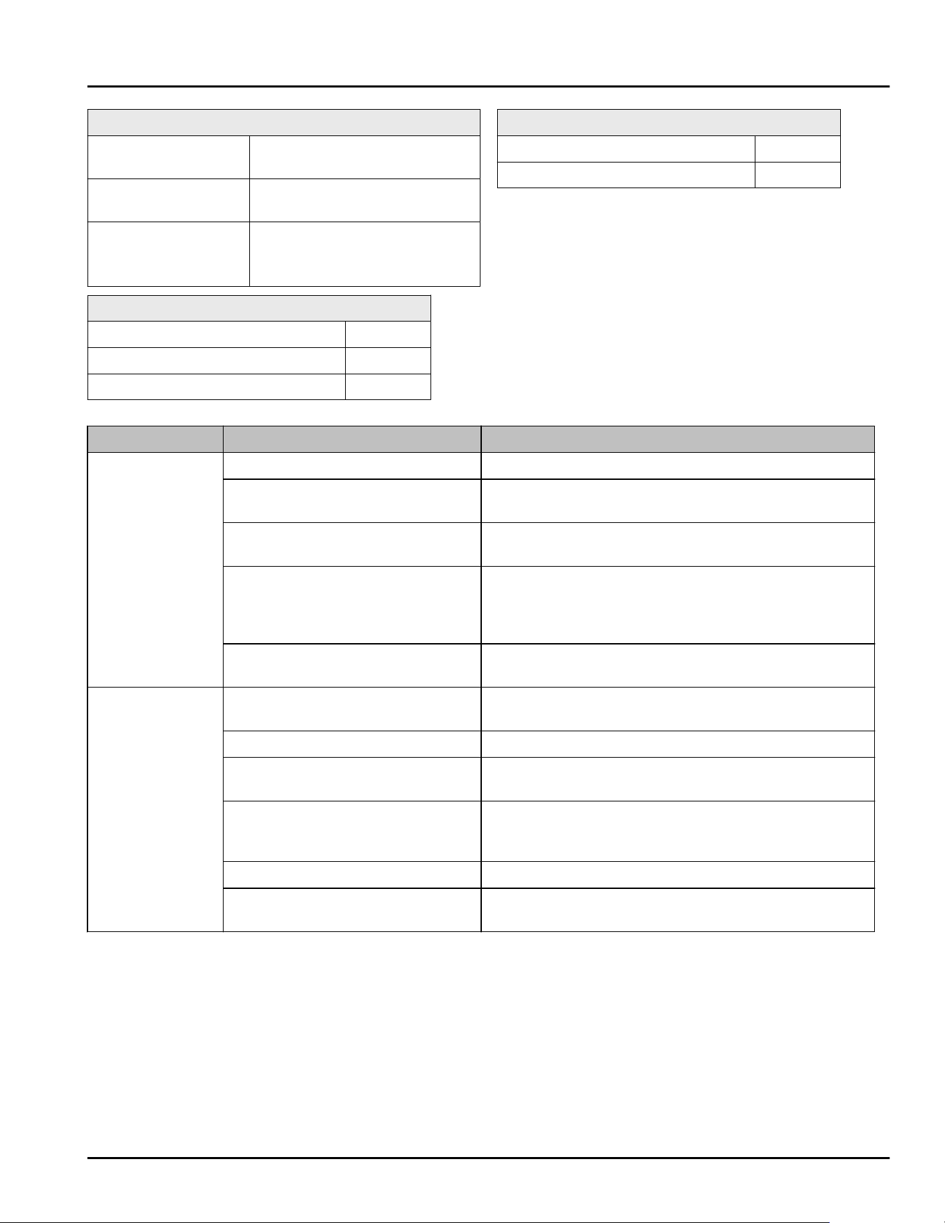
Setup conditions
Ambient temperature +10 °C (50 °F) to
+35°C(95°F)
Maximum relative
ambient moisture
75%, not condensing
Maximum operating
elevation (meters
above sea level)
2000m(6,561.68ft)
1500 m (4,921.26 ft) (glass
door)
Electrical values
Nominal voltage 115-127 V~
Frequency 60Hz
Connected load 2,0A
Electrical values
Maximum power supply fluctuation +/-10%
Overvoltage categories II
9.2 Technical malfunction
Your appliance is designed and built to ensure it works
reliably and has a long service life. If a malfunction
nonetheless occurs during operation, please check
whether the malfunction is due to an operating error. If
this is the case, you will be charged for the cost
incurred even if this falls within the warranty period.
You can rectify the following malfunctions yourself.
9.2.1 Appliance function
Defect
Cause Remedy
The appliance is
not working.
The appliance is not switched on. ► Switch on the appliance.
The power plug is not properly
inserted in the socket.
► Check the power plug.
There is a problem with the wall
socket breaker.
► Check the breaker.
Power failure ► Keep the appliance closed.
► If necessary move the refrigerated/frozen items to
another fridge or freezer if the power is off for a
prolonged period.
The IEC socket is not correctly
plugged into the appliance.
► Check the IEC socket.
The temperature
is not cold
enough.
The appliance door is not closed
properly.
► Close the appliance door.
Ventilation is not sufficient. ► Unclog the ventilation grill and clean it.
The ambient temperature is too
high.
► Observe the suitable ambient conditions:
(see1.4 Range of appliance use)
The appliance was opened too
many times or for too long.
► Wait to see if the required temperature corrects
itself. If not, contact Customer Service.
(see 9.3 Customer Service)
The temperature is set incorrectly. ► Set a colder temperature and check after 24 hours.
The appliance is too close to a
heat source (stove, heater etc).
► Move either the appliance or the heat source.
9.3 Customer Service
First check whether you can remedy the fault yourself .
If this is not the case, please contact Customer
Service.
You can find the address in the enclosed brochure
“Liebherr-Service” or at home.liebherr.com/service.
Customer support
46 * Depending on model and options
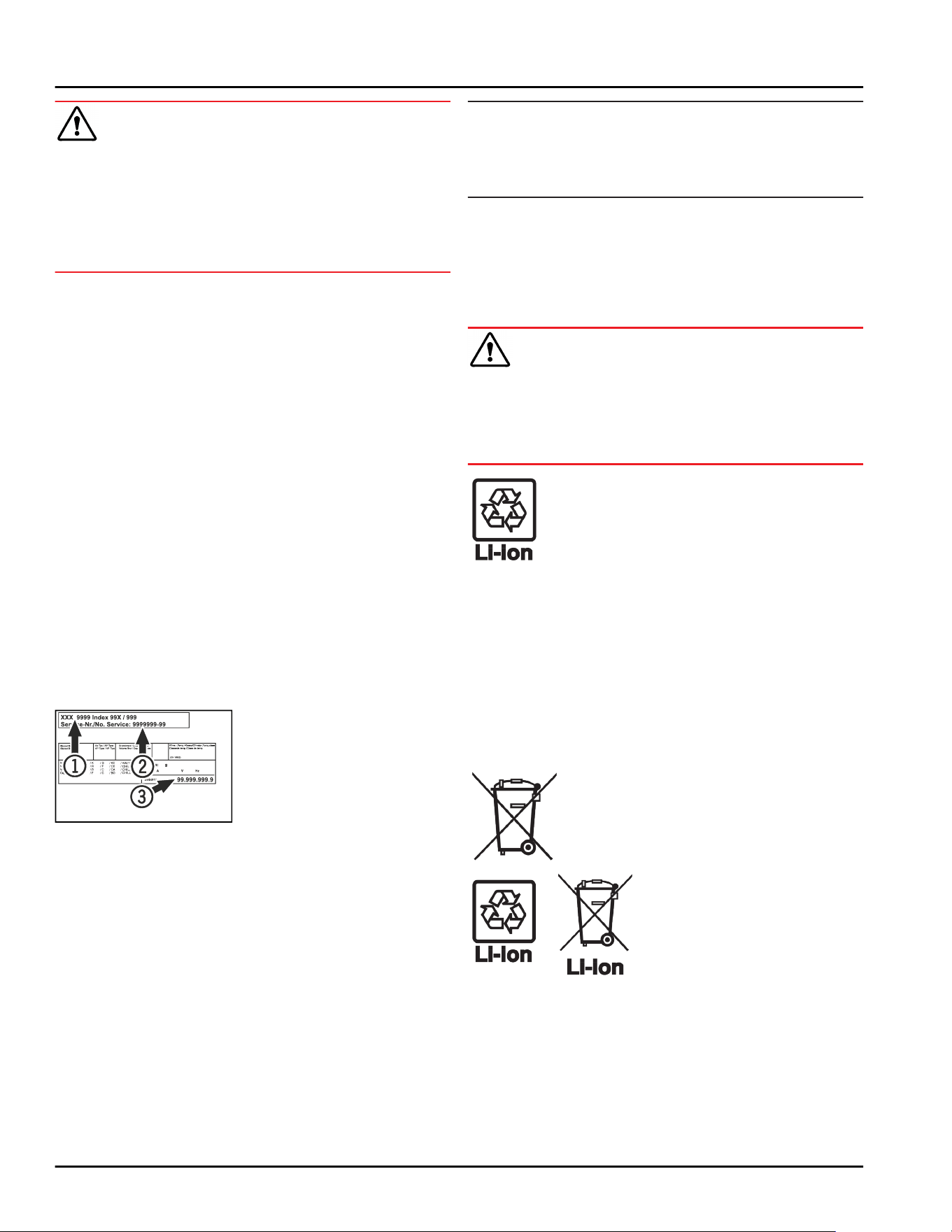
WARNING
Unprofessional repair!
Injuries.
► A damaged power cable may only be replaced by the
manufacturer, the manufacturer’s Customer Service
or a similarly qualified person.
► For appliances with plug and play connection cables,
the change can be made by the customer.
9.3.1 Contacting Customer Service
Make sure you have the following appliance informa‐
tion ready:
❑
Appliance name (model and index)
❑
Service no. (service)
❑
Serial no. (S no.)
► Access the appliance information via the display
(see 6.2.15 Appliance information ) .
-or-
► Refer to the type plate for appliance information.
(see 9.4 Type plate)
► Note appliance information.
► Inform Customer Service: Report faults and the
appliance information.
▷ This will help us to provide fast and focused service.
► Follow any further instructions provided by
Customer Service.
9.4 Type plate
The type plate is inside the appliance. See appliance
overview.
Fig. 164
(1)
Appliance designa‐
tion
(3) Serial No.
(2) Service No.
10 Shutting down
► Empty the appliance.
► Switch off appliance.
► Pull the power plug from the outlet.
► If necessary, remove the IEC socket: Pull the IEC
socket out of the appliance plug while turning it to
the left and right at the same time.
► Clean the appliance. (see 8.3Cleaning the appliance)
► If available: Remove the covers and insulation of the
sensor feed-through to prevent mold from forming.
► Leave the door open so that no bad odors form.
Note
Damage to the appliance and malfunctions!
► After shutting down, only store the appliance at the
permitted room temperature of between
-10°C(14°F) and +50°C(122°F).
11 Disposal
11.1 Preparing the appliance for
disposal
WARNING
Risk of child entrapment!
Before you throw away your old refrigerator or freezer:
► Take off the doors.
► Leave the shelves in place so that children may not
easily climb inside.
Liebherr uses batteries in some of its appli‐
ances. You should remove these before
disposal of the old appliance for environ‐
mental reasons. If your appliance contains
batteries, a corresponding notice is
attached to the appliance.
Lamps If you can remove the lamps yourself
without destroying them, also remove these
before disposal.
► Take the appliance out of operation.
► If possible: Remove lamps without destroying them.
11.2 Disposing of the appliance in an
environmentally friendly manner
The appliance still contains
valuable materials and must
be collected separately from
unsorted municipal waste so
it can be recycled.
Dispose of batteries sepa‐
rately from the old appliance.
Certain batteries should NOT
go in household garbage or
recycling bins. Waste
batteries can always be recy‐
cled or taken to household
hazardous waste collection
points. To prevent fires from
lithium-ion batteries, tape
battery terminals and/or
place batteries in separate
plastic bags and never put
these batteries in household
garbage or recycling bins.
Shutting down
* Depending on model and options 47
Lamps Dispose of removed lamps via
the respective collection
systems.
For USA: Check the Responsible Appli‐
ance Disposal (RAD) program
to find a RAD partner near
you.
For Canada: Follow your local guidance
about recycling and disposal
capabilities near you.
WARNING
Leaking refrigerant and oil!
Fire. The refrigerant contained within the appliance is
environmentally friendly, but flammable. The oil
contained within the appliance is flammable. Escaping
refrigerant and oil can ignite if they are of high enough
concentration and are exposed to an external heat
source.
► Do not damage the pipelines of the coolant circuit
and the compressor.
► Observe the notes on appliance transport.
(see 4.3 Transporting the appliance)
► Transport the appliance away without damaging it.
► Dispose of batteries, lamps, and the appliance
according to the above specifications.
12 Additional information
Further information on warranty conditions can be
found in the enclosed service brochure or on the
Internet at https://home.liebherr.com.
Additional information
48 * Depending on model and options
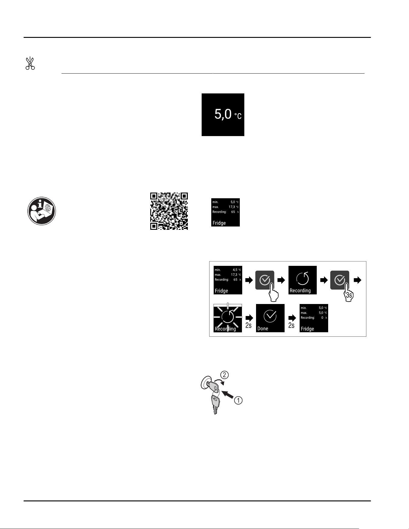
Reference in the
event of an
appliance fault:
Model ID /
Inventory number:
Quick Start Guide for everyday
use
Information about using this Quick Start Guide:
-
This Quick Start Guide is not a substitute for the full
operating instructions nor is it a substitute for
appliance training.
-
This Quick Start Guide provides support for everyday
use and handling the appliance.
-
Read the full operating instructions and the safety
instructions contained therein.
This quick start guide is for: SRFfg 35../55..
Using the QR code, you
can read the full
operating instructions.
Intended use
This laboratory refrigerator, with an interior free of
ignition sources, is suitable for professional storage of
highly flammable products in closed containers, at
temperatures between 3°C(38°F) and 16°C(60°F).
Foreseeable incorrect use
Do not use the appliance for the following applications:
-
Storage and cooling of:
•
Chemically unstable substances
•
Blood, plasma or other body fluids for the purpose
of infusion, application or introduction in the
human body
-
Use in areas with risk of explosion
-
Outdoor use or in areas where it is exposed to splash
water or damp conditions
When stocking, observe the following points:
❑
Position grid shelves according to the height
required.
❑
Observe maximum load.
❑
When the storage temperature has been reached,
load the appliance (compliance with cold chain).
❑
Keep the ventilation slots of the recirculation fan
free in the interior.
❑
Items for refrigeration must not come into contact
with the evaporator on the rear wall.
❑
Keep liquids in closed containers.
❑
Leave space when storing items for refrigeration to
ensure adequate air circulation.
Status display
Fig. 165 Status display with actual temperature
Displaying temperature recording
The temperature recording displays the length of the
recording and the minimum and maximum
temperatures measured during this period of time.
Fig. 166
Resetting temperature recording
Fig. 167
Unlocking appliance
Fig. 168
► Insert the key. Fig. 168(1)
► Turn the key clockwise by 90°. Fig. 168(2)
▷ The appliance is unlocked.
Quick Start Guide for everyday use
* Depending on model and options 49
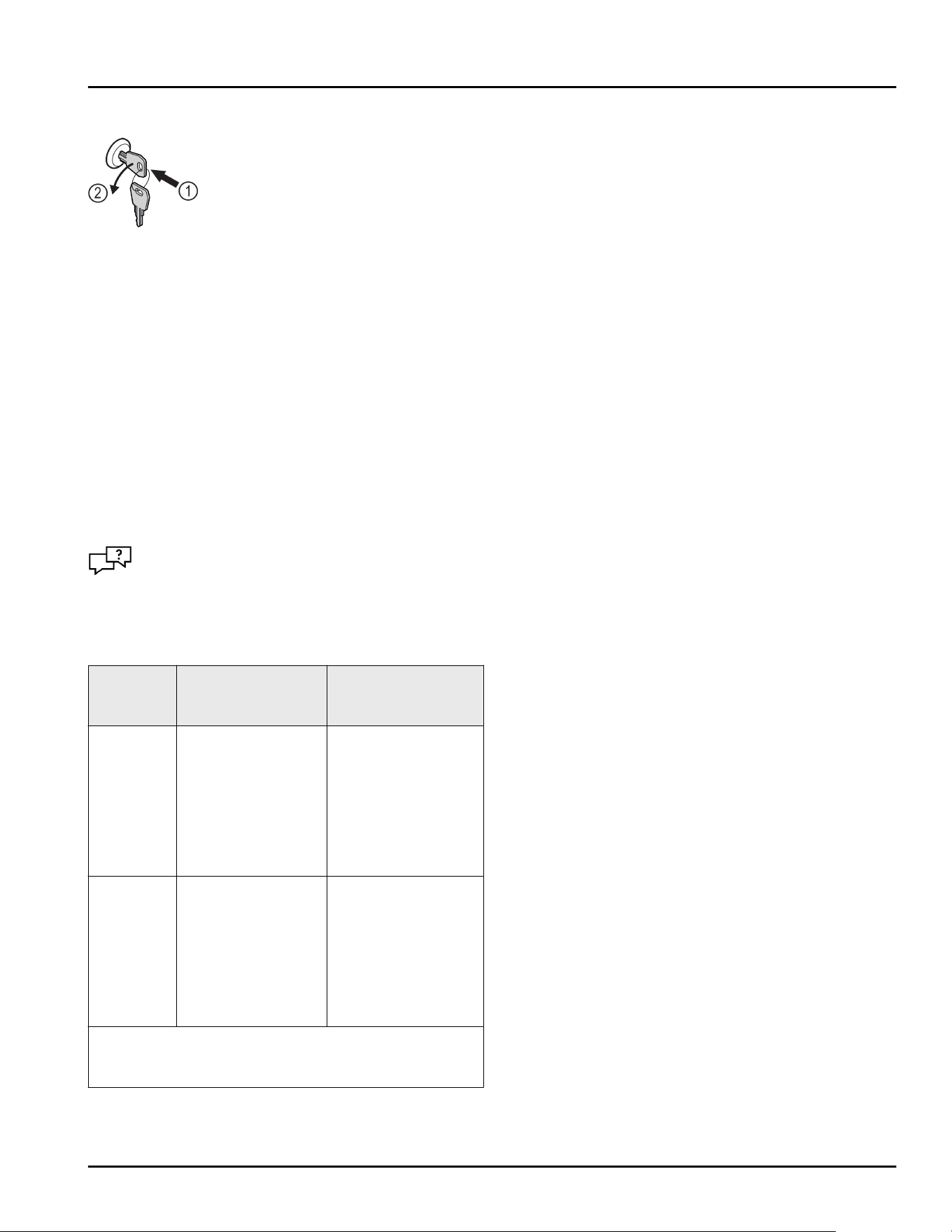
Locking appliance
Fig. 169
► Insert the key. Fig. 169(1)
► Turn the key anticlockwise by 90°. Fig. 169(2)
▷ The appliance is locked.
Cleaning appliance
► Empty the appliance.
► Pull out the power plug.
► Observe the information in the operating
instructions.
► Dry the appliance and equipment thoroughly after
cleaning.
► Connect the appliance.
► Switch on the appliance.
► Load the appliance once the storage temperature is
reached.
What should I do if there is a
fault?
A message appears in the display if there is a fault.
Messages have different meanings:
Symbol
color in
the display
Meaning Remedy
WHITE
with black
bar
Reminder
Reminder of
general
procedures. You
can carry out these
procedures to
eliminate the
message.
Consult the
operating
instructions and
perform the
troubleshooting
steps.
WHITE
Warning
Appears when
there are
malfunctions. You
can eliminate
simple
malfunctions
yourself.
Consult the
operating
instructions and
perform the
troubleshooting
steps.
If you cannot remedy the fault yourself, contact a
competent member of staff or your nearest customer
service outlet.
Quick Start Guide for everyday use
50 * Depending on model and options

home.liebherr.com/fridge-manuals
ORIGINAL OPERATOR'S MANUAL
Issue date:20250603
Part number index:7082908-00
For service in the United States and Canada: Liebherr Service Center
Toll Free: 1-844-542-6782
Email: service-commercial.us@liebherr.com
PlusOne Solutions, Inc.
3501 Quadrangle Blvd, Suite 120
Orlando, FL 32817