
User Guide
Tapo Solar Panel
©2024 TP-Link 1910013683 REV1.0.0

Contents
About This Guide ···········································································1
Introduction ······················································································ 2
Mounting Tips ··················································································3
Sce 1. Mount Solar Panel Only ···············································4
Sce 2. Mount Solar Panel & Extra Camera ·······················6
Sce 3. Mount Solar Panel and Camera KIT ······················8
Connect Solar Panel to Camera ·········································10
Authentication ··············································································12
1
About This Guide
This guide provides a brief introduction to the Tapo Solar Panel as well as regulatory information.
Please note that features available in Tapo may vary by model and software version. Tapo availability may also vary by region. All images, steps, and
descriptions in this guide are only examples and may not reect your actual Tapo experience.
Conventions
In this guide, the following convention is used:
Convention Description
Blue
Key information appears in blue, including management page text such as menus, items, buttons and so on.
Underline
Hyperlinks are in blue and underlined. You can click to redirect to a website.
Note:
Ignoring this type of note might result in a malfunction or damage to the device.
More Info
• Specications can be found on the product page at https://www.tapo.com.
• Our Technical Support and troubleshooting information can be found at https://www.tapo.com/support/.
• Mounting and connection videos can be found at https://www.tp-link.com/support/setup-video/#cloud-cameras.

2
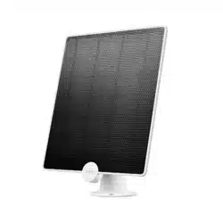
Introduction
Tapo A201 seamlessly pairs with all Tapo Battery Cameras
§
, oering a sleek, unied look and exible positioning with a 4m charging cable for
maximum sunlight exposure. Enjoy green, endless power.
Flexible Angle Adjustment
Mount your solar panel on the wall
or roof and adjust its angle exibly
to capture enough sunlight with an
angle-adjustable bracket.
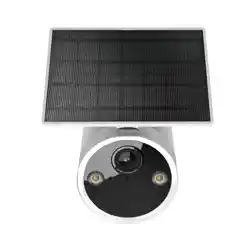
High-Eciency Solar Charging
Daily 45 minutes
△
of direct sunlight
charges any Tapo Battery Camera
for all-day use, thanks to its 2.5W
†
maximum charging power.
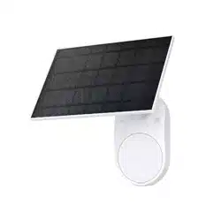
IP65 Weatherproof
Oers reliable performance and keeps
your battery camera charged even
in harsh environments with rain and
dust.
§
A solar panel can only connect to one camera at a time. The Tapo Solar Panel is compatible with all Tapo Battery Security Cameras. Due to Tapo C425's unique magnetic base, it exclusively supports detached installation. Visit the Tapo website for all
supported products.
†
Actual charging power may vary based on installation location, weather conditions, temperature, and other environmental factors.
△
45 min of sunlight time is based on standard environmental conditions (1000W/m2, 25°C, AM1.5) and specied working scenes (100 events triggered per day). Actual required time of sunlight may vary.
3
Mounting Tips
Read mounting tips before you mount the solar panel.
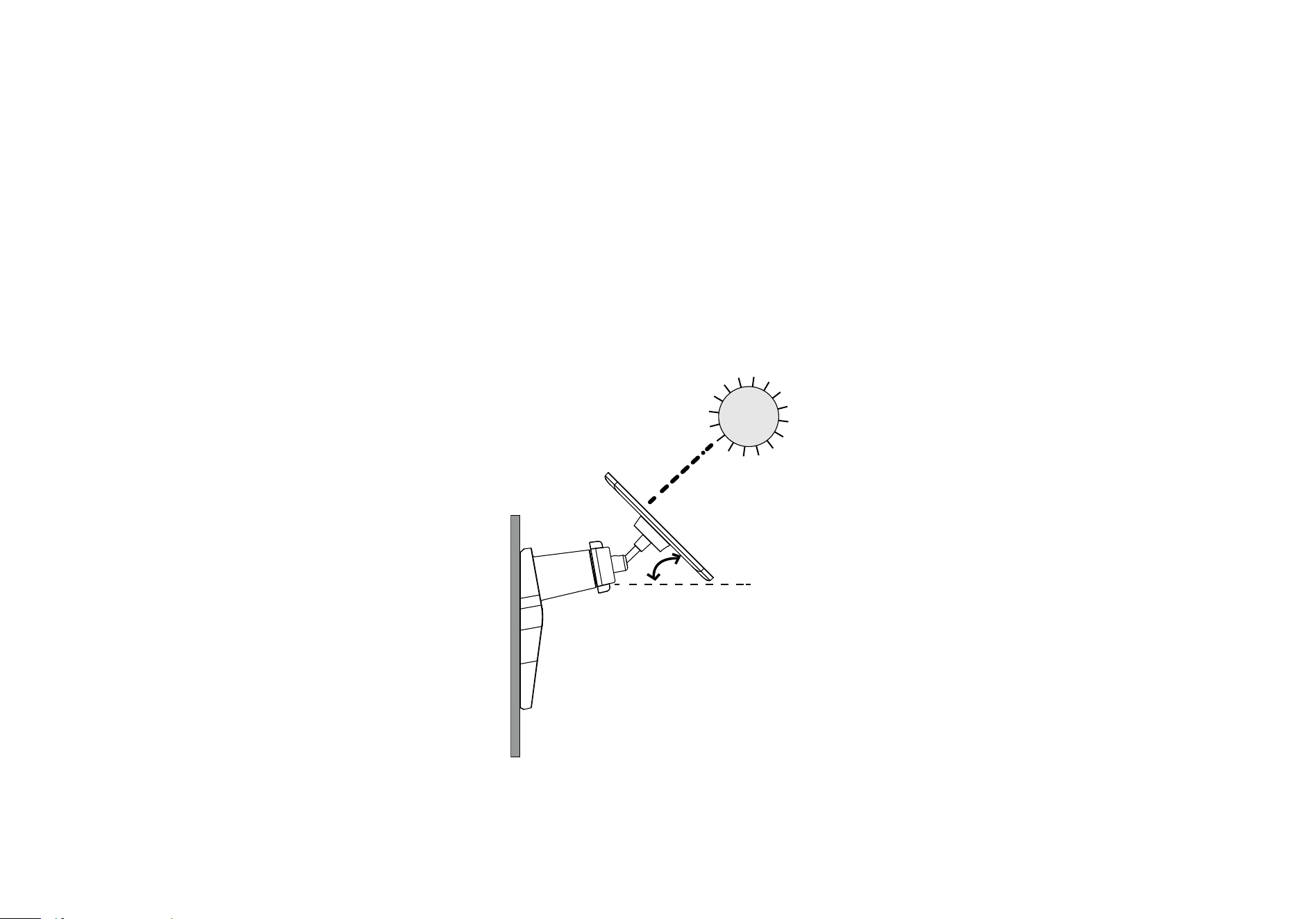
The solar panel captures free, clean solar energy and provides non-stop power supply for your Tapo cameras. The position and tilt angle of the solar
panel greatly aects the solar eciency.
1. Choose a location where the solar panel gets the most sunlight throughout the year.
2. Position the panel south-facing in the Northern Hemisphere or north-facing in the Southern Hemisphere. The recommended tilt angle between the
panel and the horizontal ground is 35° ~ 45°.
3. Regularly wipe the panel to remove dust and debris.
35°-45°
4
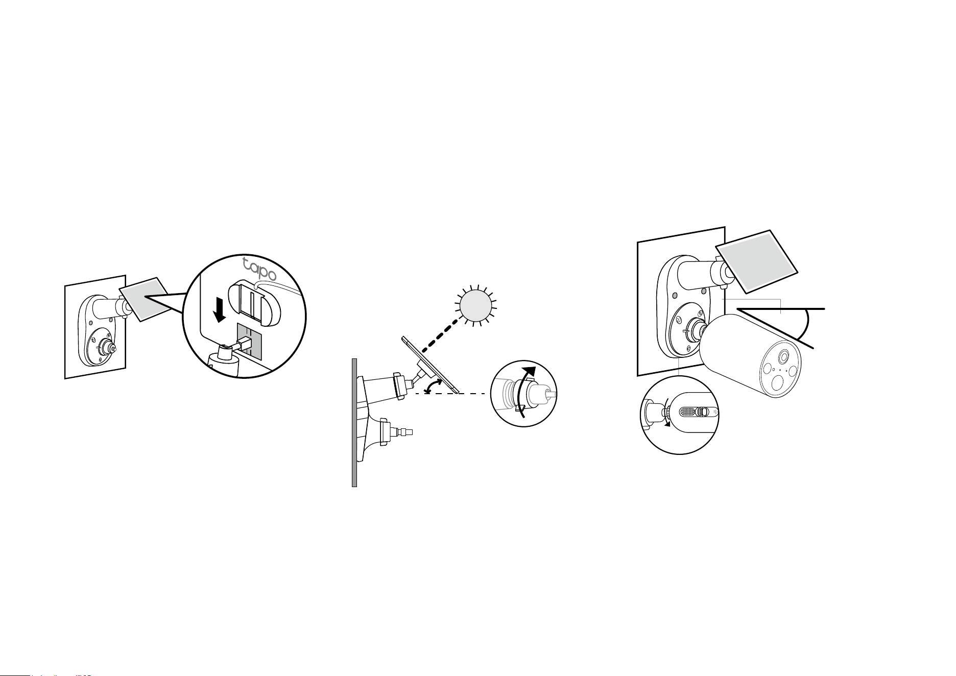
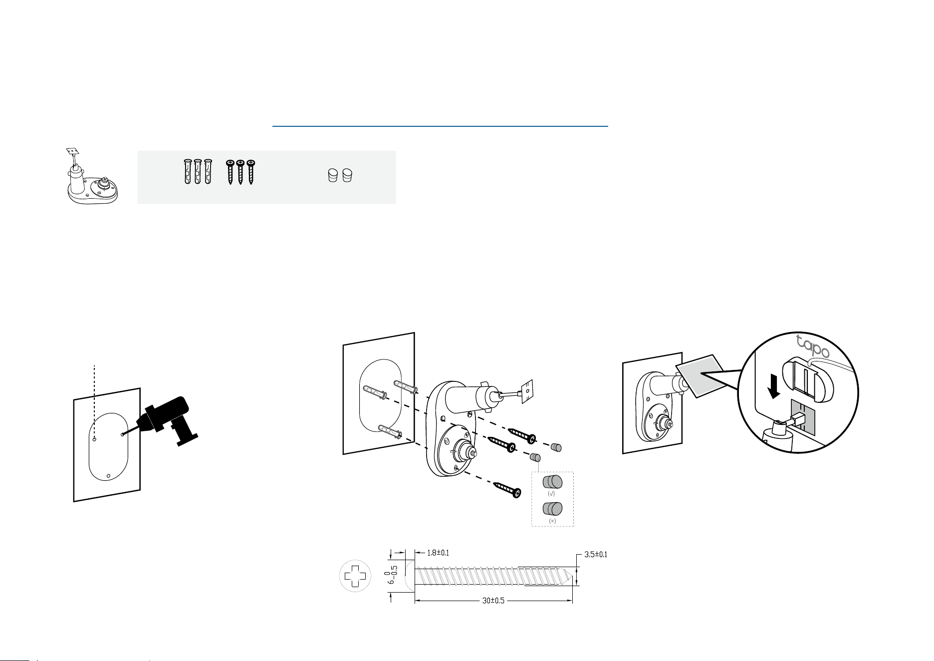
3. Install the Solar Panel
Slide the solar panel onto the mounting
bracket until it clicks into place.
Back Side
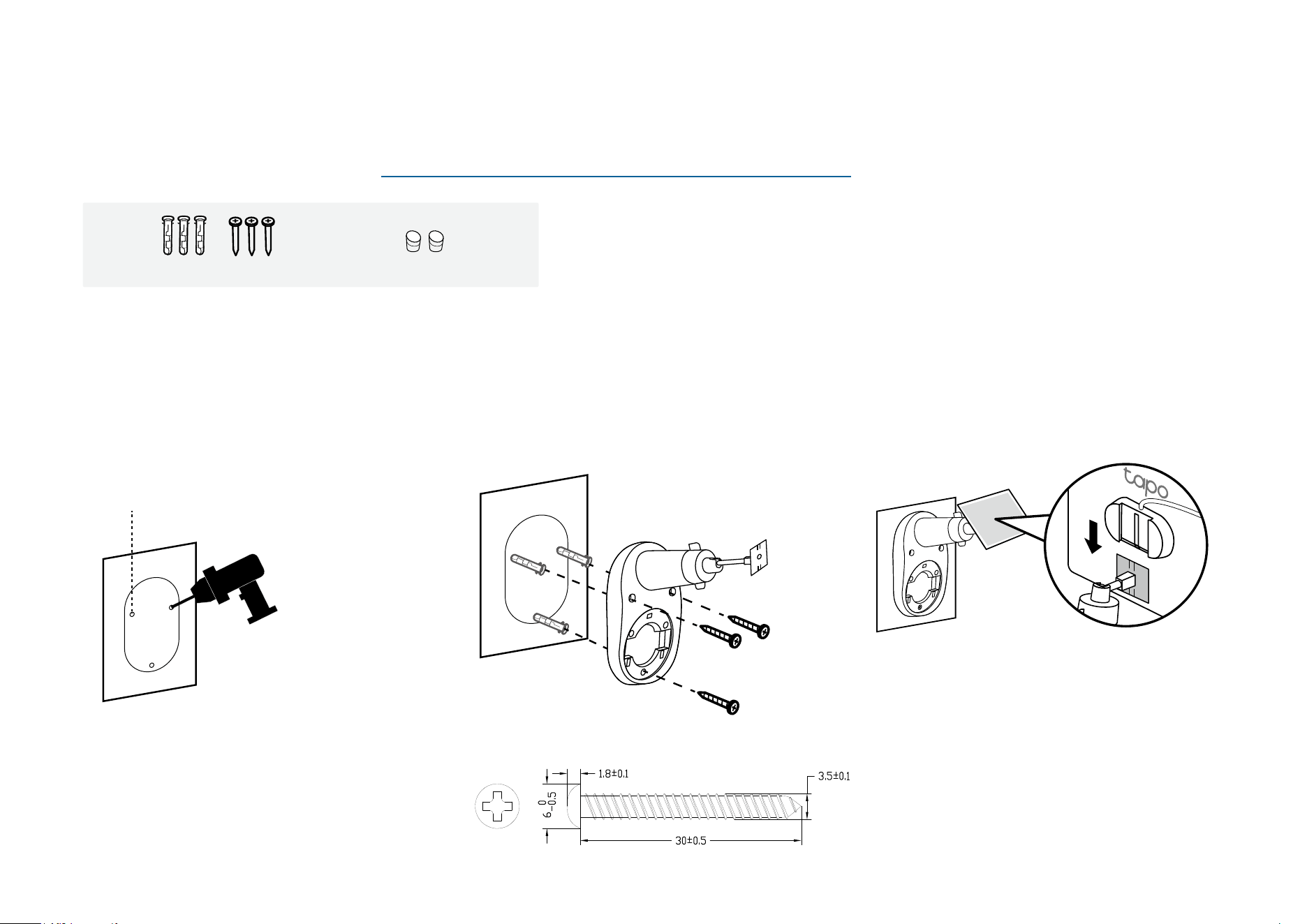
2. Mount Bracket
Insert three wall anchors into the holes and
use the mounting screws to ax the solar
panel bracket over the anchors.
Sce 1. Mount Solar Panel Only
For the mounting video, please refer to https://www.tp-link.com/support/setup-video/#cloud-cameras
1. Drill Holes
Stick the mounting template to a solid and
level wall surface. Drill three screw holes
according to the template.
Φ=6 mm (15/64 in.)
Wall Anchors ×3 + Self-tapping Screws ×3 Screw Caps ×2
5
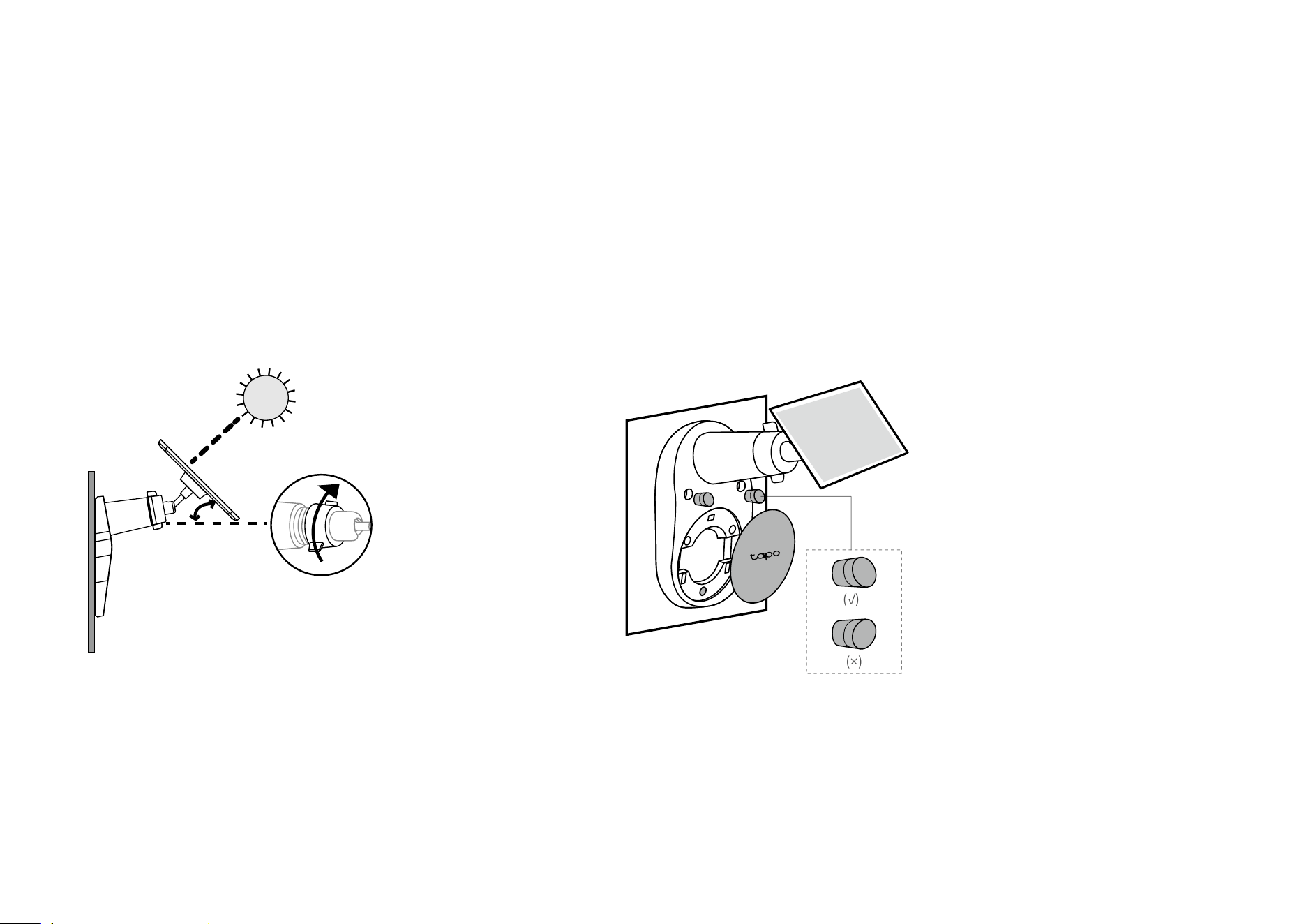
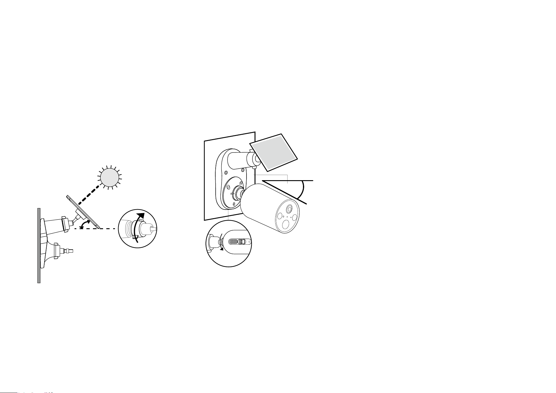
4. Adjust Solar Panel Angle
Loosen the adjustable screw, tilt the solar panel to
adjust the angle, and then tighten the adjustable screw.
The recommended tilt angle between the panel and the
horizontal ground is 35° ~ 45°.
35°-45°
5. Install Screw Caps & Base Cover
Insert two screw caps into the screw holes until ush,
then install the base cover.
(√)
(×)
6
3. Mount Bracket
Insert three wall anchors into the holes and
use the mounting screws to ax the solar
panel bracket over the anchors. Then, insert
two screw caps into the upper screw holes.
(√)
(×)
Sce 2. Mount Solar Panel & Extra Camera
For the mounting video, please refer to https://www.tp-link.com/support/setup-video/#cloud-cameras
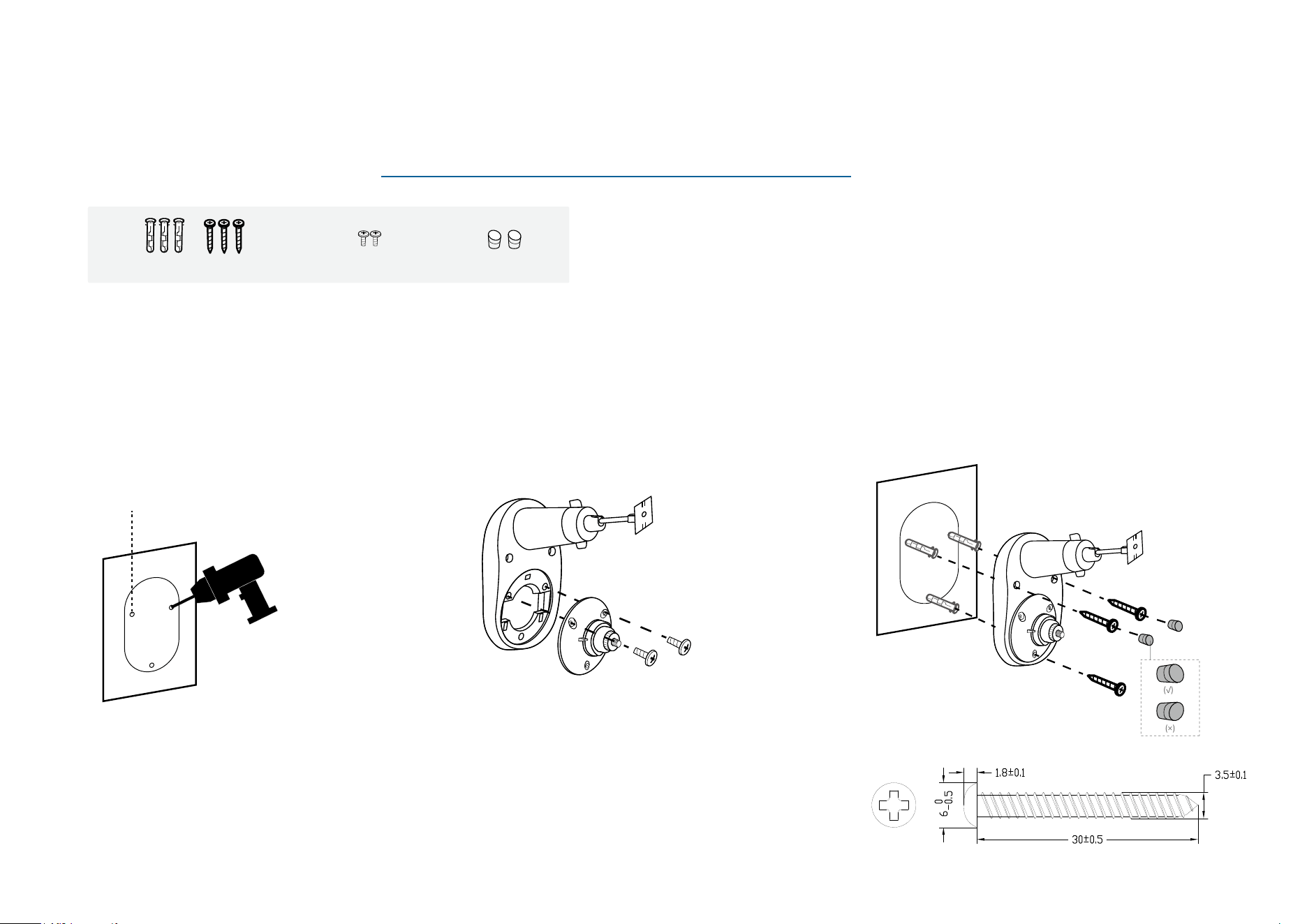
1. Drill Holes
Stick the mounting template to a solid and
level wall surface. Drill three screw holes
according to the template.
Φ=6 mm (15/64 in.)
2. Install Camera Bracket
Secure the camera bracket to the solar panel
bracket using two screws.
The third hole below is for securing the solar
panel bracket.
Camera Bracket Screws ×2
Wall Anchors ×3 + Self-tapping Screws ×3
Screw Caps ×2
7
4. Install the Solar Panel
Slide the solar panel onto the mounting
bracket until it clicks into place.
5. Adjust Solar Panel Angle
Loosen the adjustable screw, tilt the solar
panel to adjust the angle, and then tighten the
adjustable screw.
The recommended tilt angle between the
panel and the horizontal ground is 35° ~ 45°.
35°-45°
6. Install Camera & Adjust Angle
Install the camera onto the bracket and adjust
the camera angle as per the camera's guide.
Camera-suggested
Angle
Ensure the camera is securely attached to
the camera bracket by tightening the bottom
screw.
*Here we take the Tapo Camera C410 as an example.
8
Sce 3. Mount Solar Panel and Camera KIT
For the mounting video, please refer to https://www.tp-link.com/support/setup-video/#cloud-cameras
1. Drill Holes
Stick the mounting template to a solid and
level wall surface. Drill three screw holes
according to the template.
Φ=6 mm (15/64 in.)
2. Mount Bracket
Insert three wall anchors into the holes and
use the mounting screws to ax the solar
panel bracket over the anchors. Then, insert
two screw caps into the upper screw holes.
(√)
(×)
3. Install the Solar Panel
Slide the solar panel onto the mounting
bracket until it clicks into place.
Wall Anchors ×3 + Self-tapping Screws ×3 Screw Caps ×2
9
4. Adjust Solar Panel Angle
Loosen the adjustable screw, tilt the solar
panel to adjust the angle, and then tighten the
adjustable screw.
The recommended tilt angle between the
panel and the horizontal ground is 35° ~ 45°.
35°-45°
5. Install Camera & Adjust Angle
Install the camera onto the bracket and adjust
the camera angle as per the camera's guide.
Camera-suggested
Angle
Ensure the camera is securely attached to
the camera bracket by tightening the bottom
screw.
*Here we take the Tapo Camera C410 as an example.
10
Connect Solar Panel to Camera
Use the appropriate waterproof gasket when connecting the solar panel to your camera. The gasket protects your camera from exposed moisture and
dust that may damage the camera.
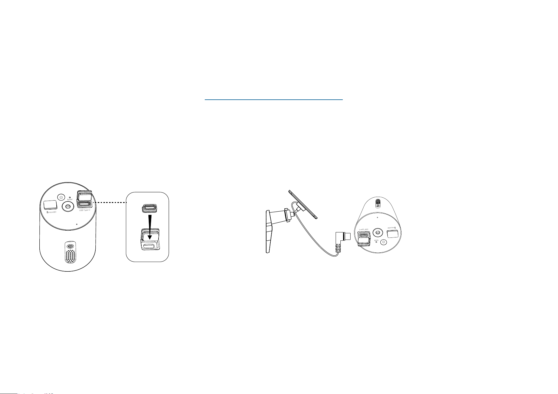
1. Install Waterproof Gasket
Insert the waterproof gasket into the camera’s charging
port. Ensure that the gasket is tightly sealed.
2. Power On Camera
Connect the solar panel by inserting the connector with the
black ring into the charging port until snug.
*Here we take the Tapo Camera C410 as an example.
For detailed connection instructions, please refer to https://www.tp-link.com/support/faq/3800/
11
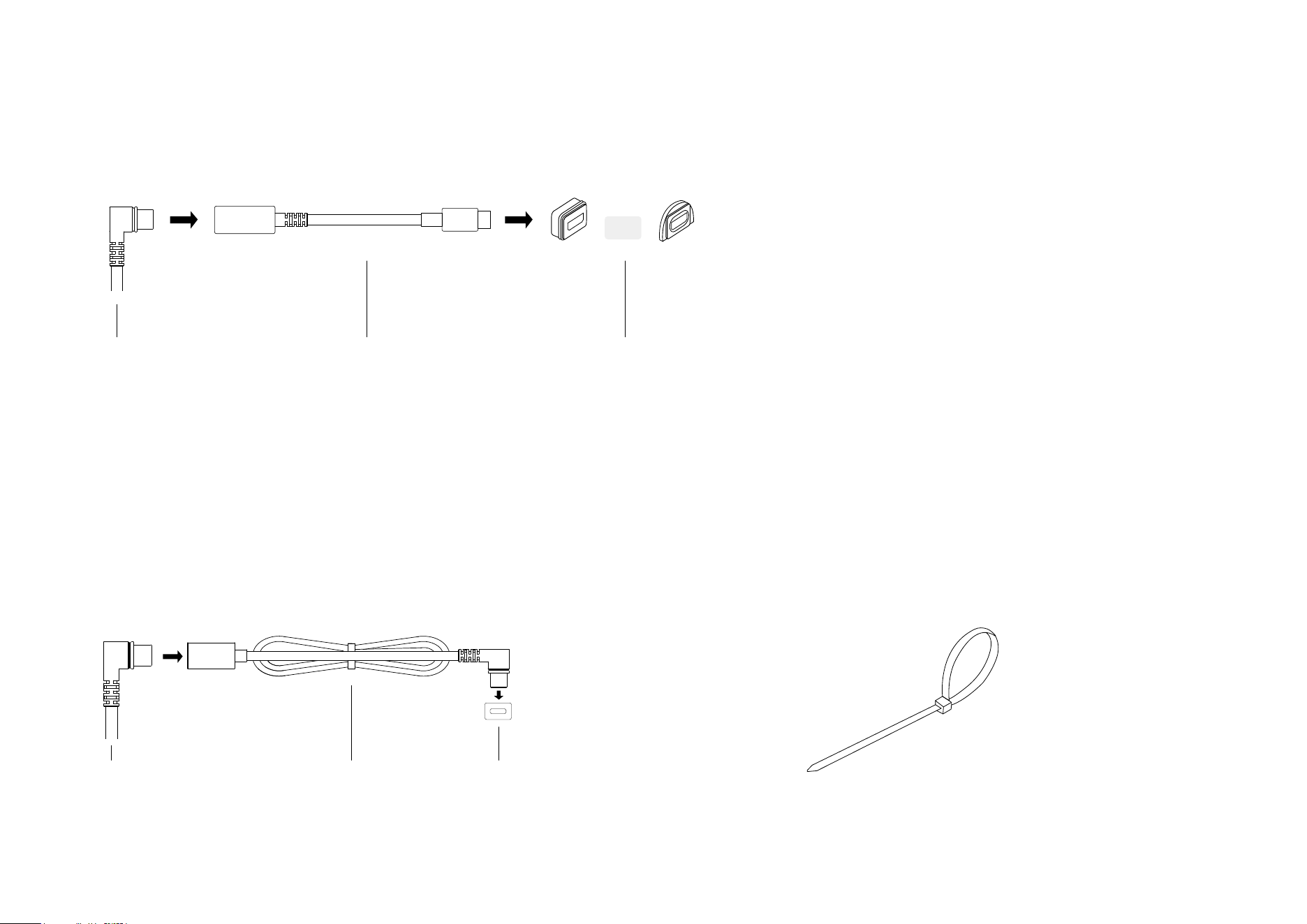
USB Adapter for Micro USB charging port
A USB adapter is required for a camera with a Micro USB charging port. Choose the
appropriate Micro USB waterproof gasket for connection.
Solar Panel Connector
OR
Micro USB GasketUSB Adapter
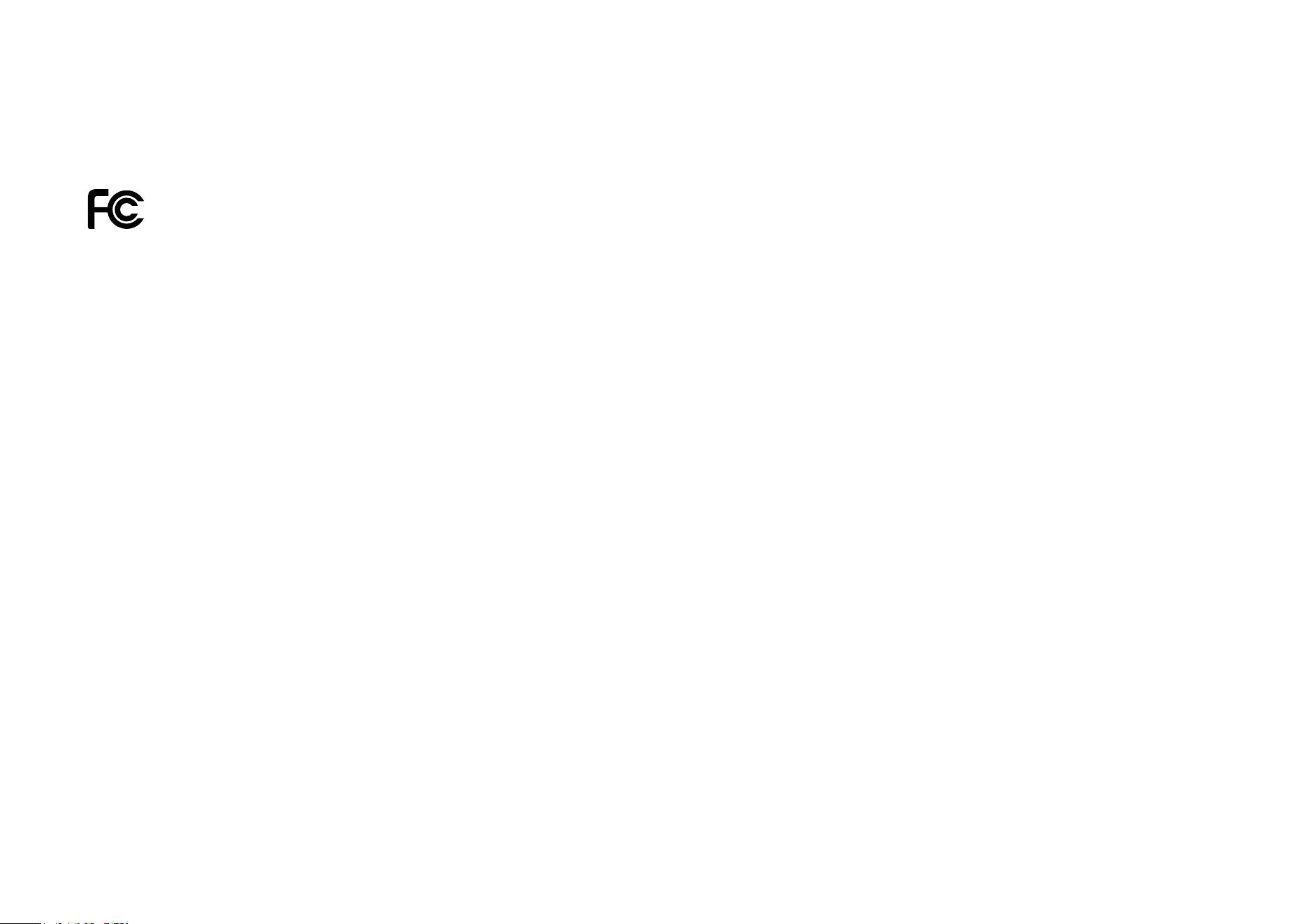
If the power cable is too short...
Extend the power cable using the provided extension cable.
Insert the connector with the black ring into the extension
until snug and use the appropriate gasket when connecting
the solar panel to your camera.
Extension CableSolar Panel Connector Waterproof Gasket
If the power cable is too long...
Use the cable zip tie provided to bundle up the excess
cable. Once tightened, the zip tie cannot be easily
adjusted. To release the tie, you will need to cut the zip tie.
Authentication
FCC compliance information statement
Product Name: Tapo Solar Panel
Model Number: Tapo A201
Responsible Party:
TP-Link USA Corporation
Address: 10 Mauchly, Irvine, CA 92618
Website: http://www.tp-link.com/us/
Tel: +1 626 333 0234
Fax: +1 909 527 6804
E-mail: [email protected]om
This equipment has been tested and found to comply with the limits for a Class B digital device, pursuant to part 15 of the FCC Rules. These limits are
designed to provide reasonable protection against harmful interference in a residential installation. This equipment generates, uses and can radiate
radio frequency energy and, if not installed and used in accordance with the instructions, may cause harmful interference to radio communications.
However, there is no guarantee that interference will not occur in a particular installation. If this equipment does cause harmful interference to radio
or television reception, which can be determined by turning the equipment off and on, the user is encouraged to try to correct the interference by
one or more of the following measures:
• Reorient or relocate the receiving antenna.
• Increase the separation between the equipment and receiver.
• Connect the equipment into an outlet on a circuit different from that to which the receiver is connected.
• Consult the dealer or an experienced radio/ TV technician for help.
This device complies with part 15 of the FCC Rules. Operation is subject to the following two conditions:
1. This device may not cause harmful interference.
2. This device must accept any interference received, including interference that may cause undesired operation.

Any changes or modifications not expressly approved by the party responsible for compliance could void the user’s authority to operate the
equipment.
We, TP-Link USA Corporation, has determined that the equipment shown as above has been shown to comply with the applicable technical standards,
FCC part 15. There is no unauthorized change is made in the equipment and the equipment is properly maintained and operated.
Issue Date: 2024-05-10
CE Mark Warning
This is a class B product. In a domestic environment, this product may cause radio interference, in which case the user may be required to take
adequate measures.
EU Declaration of Conformity
TP-Link hereby declares that the device is in compliance with the essential requirements and other relevant provisions of directives 2014/30/EU,
2014/35/EU, 2011/65/EU and (EU)2015/863.
The original EU declaration of conformity may be found at https://www.tapo.com/support/ce/
UKCA Mark
UK Declaration of Conformity
TP-Link hereby declares that the device is in compliance with the essential requirements and other relevant provisions of the Electromagnetic
Compatibility Regulations 2016 and Electrical Equipment (Safety) Regulations 2016.
The original UK declaration of conformity may be found at https://www.tapo.com/support/ukca/
Canadian Compliance Statement
This device contains licence-exempt transmitter(s)/receiver(s) that comply with Innovation, Science and Economic Development Canada’s licence-
exempt RSS(s). Operation is subject to the following two conditions:
1. This device may not cause interference.
2. This device must accept any interference, including interference that may cause undesired operation of the device.
L’émetteur/récepteur exempt de licence contenu dans le présent appareil est conforme aux CNR d’Innovation, Sciences et Développement
économique Canada applicables aux appareils radio exempts de licence. L’exploitation est autorisée aux deux conditions suivantes :
1. l’appareil ne doit pas produire de brouillage;
2. l’utilisateur de l’appareil doit accepter tout brouillage radioélectrique subi, meme si le brouillage est susceptible d’en compromettre le fonctionnement
Industry Canada Statement
CAN ICES-3 (B)/NMB-3(B)
Korea Warning Statements:
당해 무선설비는 운용중 전파혼신 가능성이 있음.
Продукт сертифіковано згідно с правилами системи УкрСЕПРО на відповідність вимогам нормативних документів та вимогам,
що передбачені чинними законодавчими актами України.
Safety Information
• Keep the device away from fire or hot environments. DO NOT immerse in water or any other liquid.
• Do not attempt to disassemble, repair, or modify the device. If you need service, please contact us.
• Avoid scratching and hitting the surface of the solar panel during use.
• Avoid contact with highly corrosive substances during use.
• The suitable temperature for Tapo A201 and accessories is -20°C~45°C. The working temperature range for battery charging should be maintained
at 0°C~45°C.
• Make sure the USB connector is fully plugged into your Tapo device.
• Make sure you follow the user manual to install the solar panel correctly.
• Make sure the waterproof gasket and other accessories can protect the connectors on your Tapo device.
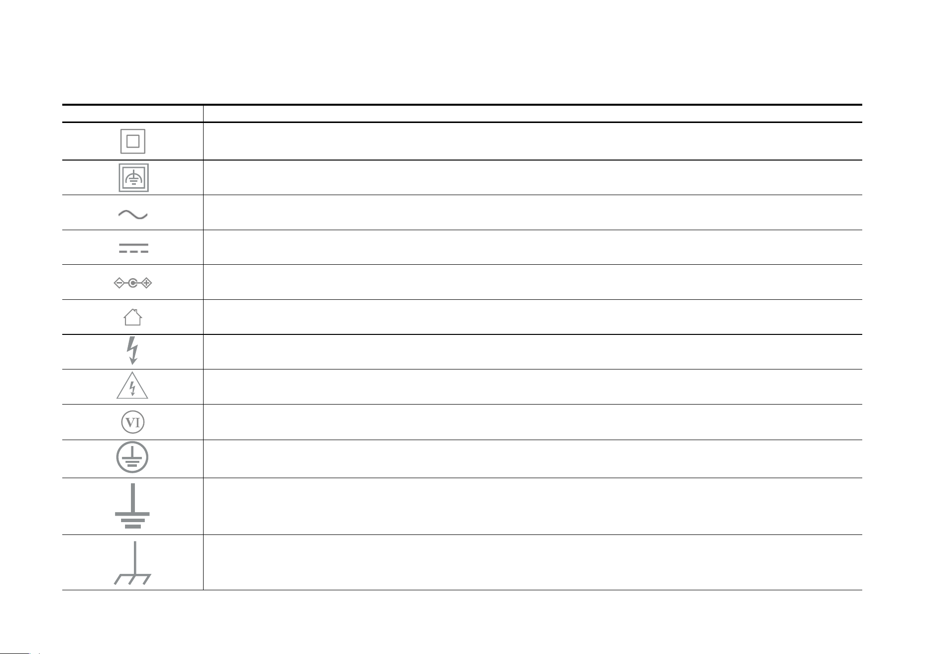
Explanation of the symbols on the product label
Note: Symbols may vary from products.
Symbol Explanation
Class II equipment
Class II equipment with functional earthing
Alternating current
DC voltage
Polarity of output terminals
Indoor use only
Dangerous voltage
Caution, risk of electric shock
Energy efficiency Marking
Protective earth
Earth
Frame or chassis
• Please read and follow the above safety information when operating the device. We cannot guarantee that no accidents or damage will occur due
to improper use of the device. Please use this product with care and operate at your own risk.
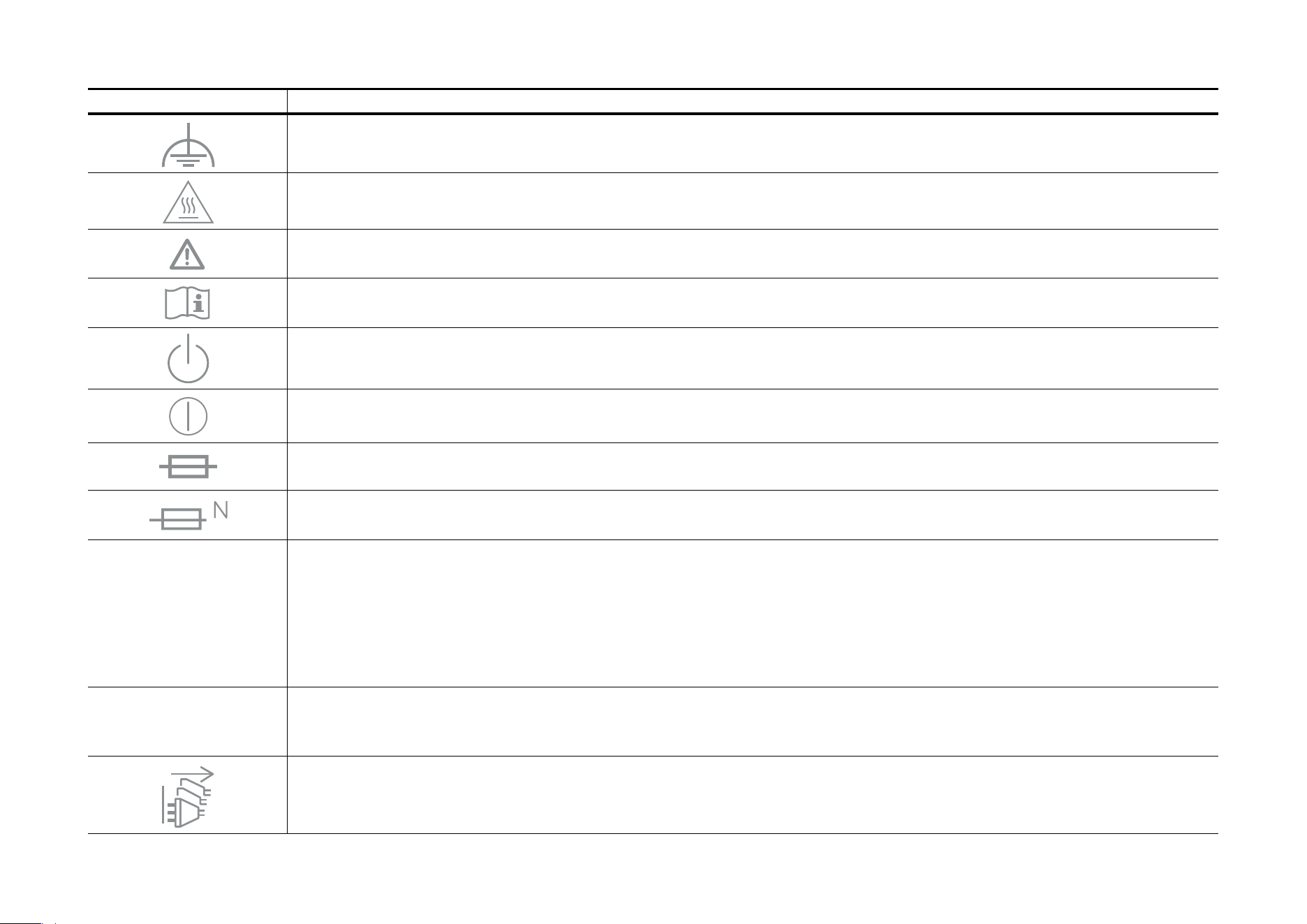
Symbol Explanation
Functional earthing
Caution, hot surface
Caution
Operator’s manual
Stand-by
“ON”/”OFF” (push-push)
Fuse
Fuse is used in neutral N
RECYCLING
This product bears the selective sorting symbol for Waste electrical and electronic equipment (WEEE). This means
that this product must be handled pursuant to European directive 2012/19/EU in order to be recycled or dismantled to
minimize its impact on the environment.
User has the choice to give his product to a competent recycling organization or to the retailer when he buys a new
electrical or electronic equipment.
Caution, avoid listening at high volume levels for long periods
Disconnection, all power plugs
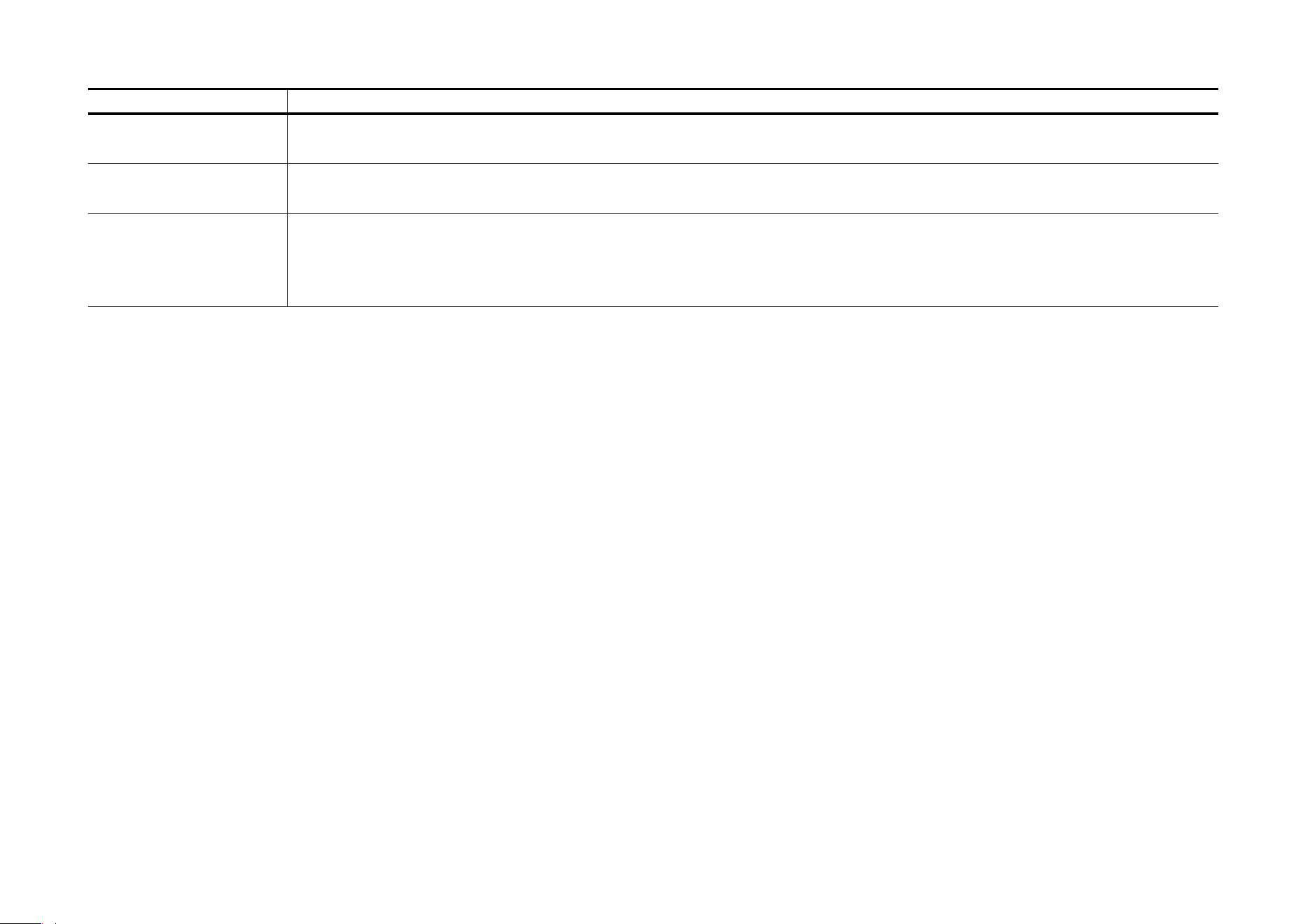
Symbol Explanation
m Switch of mini-gap construction
µ
Switch of micro-gap construction (for US version)
Switch of micro-gap / micro-disconnection construction (for other versions except US)
ε Switch without contact gap (Semiconductor switching device)