
2

3
CONTENTS
TECHNICAL DATA .................................................................................................................................3
INTRODUCTION ..................................................................................................................................... 4
SAFETY INFORMATION ....................................................................................................................... 4
GENERAL SAFETY RULES ................................................................................................................... 5
SPECIFIC SAFETY RULES FOR LOG SPLITTER ............................................................................... 9
SYMBOLS ...............................................................................................................................................10
KNOWING YOUR LOG SPLITTER ..................................................................................................... 11
MAINTENANCE .................................................................................................................................... 15
EXPLODED VIEW & PARTS LIST ...................................................................................................... 17
WARRANTY .......................................................................................................................................... 19
TECHNICAL DATA
Electric Log Splitter 701000184
Motor: 120V, 60 Hz, 15A, IP54
Splitting force: 7 Tons
Cycle time: 24 Seconds
Motor speed: 3450 RPM
Log capacity: 10 inch Diameter
20 inch Length
Hydraulic pressure: 3200 PSI
Hydraulic fluid: AW32 hydraulic fluid for operation over 40°F
or automatic transmission fluid for operation below 40°F
Hydraulic tank capacity: 3.2Quarts
Cylinder stroke: 16.5 inch
Package Dimensions (LxWxH): 38.8 x 12.8 x 20 inch
Gross Weight: 112 lbs

4
INTRODUCTION
Thank You for Purchasing a PowerSmart
®
Product. This manual provides information regarding the safe
operation and maintenance of this product. Every effort has been made to ensure the accuracy of the
information in this manual. PowerSmart
®
reserves the right to change this product and specifications at
any time without prior notice.
Please keep this manual available to all users during the entire life of the log splitter.
This manual contains special messages to bring attention to potential safety concerns, log
splitter damage as well as helpful operating and servicing information. Please read all the
information carefully to avoid injury and machine damage.
QUESTIONS? PROBLEMS?
Please contact our Customer Service Dept. with any questions and/or comments, either by Email:
available Mon-Fri 9am-5pm EST to help solve any issues that you might encounter.
SAFETY INFORMATION
Before operating this log splitter, read and observe all warnings, cautions, and instructions on the log
splitter and in this Owner’s Manual.
NOTE: The following safety information is not meant to cover all possible conditions and situations that
may occur. Read the entire Owner’s Manual for safety and operating instructions. Failure to follow
instructions and safety information could result in serious injury or death.
This safety alert symbol is used to identify safety information about hazards that can result in personal
injury.
A signal word (DANGER, WARNING, or CAUTION) is used with the alert symbol to indicate
the likelihood and the potential severity of injury. In addition, a hazard symbol may be used to
represent the type of hazard.
DANGER Indicates a hazard, which, if not avoided, will result in death or serious injury.
WARNING Indicates a hazard, which, if not avoided, could result in death or serious injury.
CAUTION Indicates a hazard, which, if not avoided, might result in minor or moderate injury.
CAUTION Without the alert symbol, indicates a situation that could result in damage.

5
GENERAL SAFETY RULES
Safety is a combination of common sense, staying alert, and knowing how your log splitter works.
SAVE THESE SAFETY INSTRUCTIONS.
Work Area Safety
Keep work area clean and well lit. Cluttered or dark areas invite accidents.
Do not operate power tools in explosive atmospheres, such as in the presence of flammable liquids,
gases or dust. Power tools create sparks which may ignite the dust or fumes.
Keep children and bystanders away while operating a power tool. Distractions can cause you to lose
control.
Personal safety
Stay alert, watch what you are doing and use common sense when operating a power tool. Do not use
a power tool while you are tired or under the influence of drugs, alcohol or medication. A moment of
attention while operating power tools may result in serious personal injury
Use personal protective equipment. Always wear eye protection. Protective equipment such as a dust
mask, non-skid safety shoes, hardhat or hearing protection used for appropriate conditions will
reduce personal injuries.
Prevent unintentional starting . Ensure the switch is in the off-position before connecting to power
source and/or battery pack, picking up or carrying the tool. Carrying power tools with your finger on
the switch or energizing power tools that have the switch on invites accidents.
Remove any adjusting key or wrench before turning the power tool on. A wrench or a key left
attached to a rotating part of the power tool may result in personal injury.
Do not overreach. Keep proper footing and balance at all times. This enables better control of the
power tool in unexpected situations.
Dress properly. Do not wear loose clothing or jewellery. Keep your hair, clothing and gloves away
from moving parts. Loose clothes, jewellery or long hair can be caught in moving parts
If devices are provided for the connection of dust extraction and collection facilities, ensure these are
connected and properly used. Use of dust collection can reduce dust-related hazards.
Do not let familiarity gained from frequent use of tools allow you to become complacent and ignore
tool safety principles. A careless act,on can cause severe m1ury within a fraction of a second.
Electrical Safety
Grounding instructions
IN THE EVENT OF A MALFUNCTION OR BREAKDOWN, grounding provides the path of least
resistance for electric current and reduces the risk of electric shock. This tool is equipped with an electric
cord that has an equipment grounding conductor and a grounding plug. The plug MUST be plugged into
a matching outlet that is properly installed and grounded in accordance with ALL local codes and
ordinances.
DO NOT MODIFY THE PLUG PROVIDED. If it will not fit the outlet, have the proper outlet installed
by a licensed electrician.
IMPROPER CONNECTION of the equipment grounding conductor can result in electric shock. The
conductor with the green insulation (with or without yellow stripes) is the equipment grounding
6
conductor. If repair or replacement of the electric cord or plug is necessary, DO NOT connect the
equipment grounding conductor to a live terminal.
CHECK with a licensed electrician or service personnel if you do not completely understand the
grounding instructions, or if you are not sure if the tool is properly grounded.
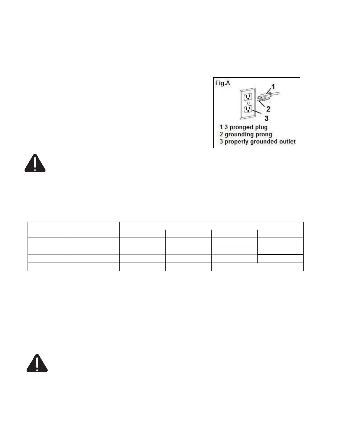
USE ONLY THREE-WIRE EXTENSION CORDS that have 3-pronged plugs and outlets that accept the
tool's plug as shown in Fig. A. Repair or replace a damaged or worn
cord immediately.
CAUTION: In all cases, make certain the outlet in question is
properly grounded. If you are not sure if it is, have a licensed
electrician check the outlet.
Guidelines for using extension cords
Make sure your extension cord is in good condition. When using an
extension cord, be sure to use one heavy enough to carry the current your product will draw. An
undersized cord will cause a drop in line voltage resulting in loss of power and overheating.
The table below shows the correct size to be used according to cord length and nameplate
ampere rating. If in doubt, use the next heavier gauge. The smaller the gauge number, the heavier the
cord.
Minimum Gauge for Extension Cords (AWG)
(When using 120 V only)
Ampere Rating
Total Length of Cord in feet
More Than
Not More Than
25
50
100
150
0
6
18
16
16
14
6
10
18
16
14
12
10
12
16
16
14
12
12
16
14
12
Not Recommended
Make sure your extension cord is properly wired and in good condition. Always replace a damaged
extension cord or have it repaired by a qualified person before using it.
Protect your extension cords from sharp objects, excessive heat and damp or wet areas.
Use a separate electrical circuit for your tools. This circuit must not be less than a #12 wire and should be
protected with a 15 A time-delayed fuse. Before connecting the motor to the power line, make sure the
switch is in the OFF position and the electric current is rated the same as the current stamped on the motor
nameplate. Running at a lower voltage will damage the motor.
WARNING: This tool must be grounded while in use to protect the operator from electric
shock.
For All Appliances
Do not use appliances in damp or wet locations as this can be dangerous.
Do not use in the rain.
Keep children away. All visitors should be kept at a safe distance from the work area.
7
Dress properly. Do not wear loose clothing or jewellery, which can get caught in moving parts. Use of
rubber gloves and heavy footwear is recommended when working outdoors. Wear protective hair
covering to contain long hair.
Use safety glasses. Always use face or dust mask if operation is dusty.
Use the right appliance. Do not use appliance for any job except that for which it is intended.
Ground Fault Circuit Interrupter (GFCI) protection should be provided on the circuit(s) or outlet(s) to
be used for the gardening appliance. Receptacles with built-in GFCI protection may be used for this
measure of safety.
Warning—to reduce the risk of electric shock, use only with an extension cord intended for outdoor
use, such as an extension cord of cord type SW-A, SOW-A, STW-A, STOW-A, SJW-A, SJOW-A,
SJTW-A or SJTOW-A.
Extension Cord
Make sure your extension cord is in good condition and is heavy enough to carry the current your product
will draw. An undersized extension cord will cause a drop in line voltage resulting in loss of power and
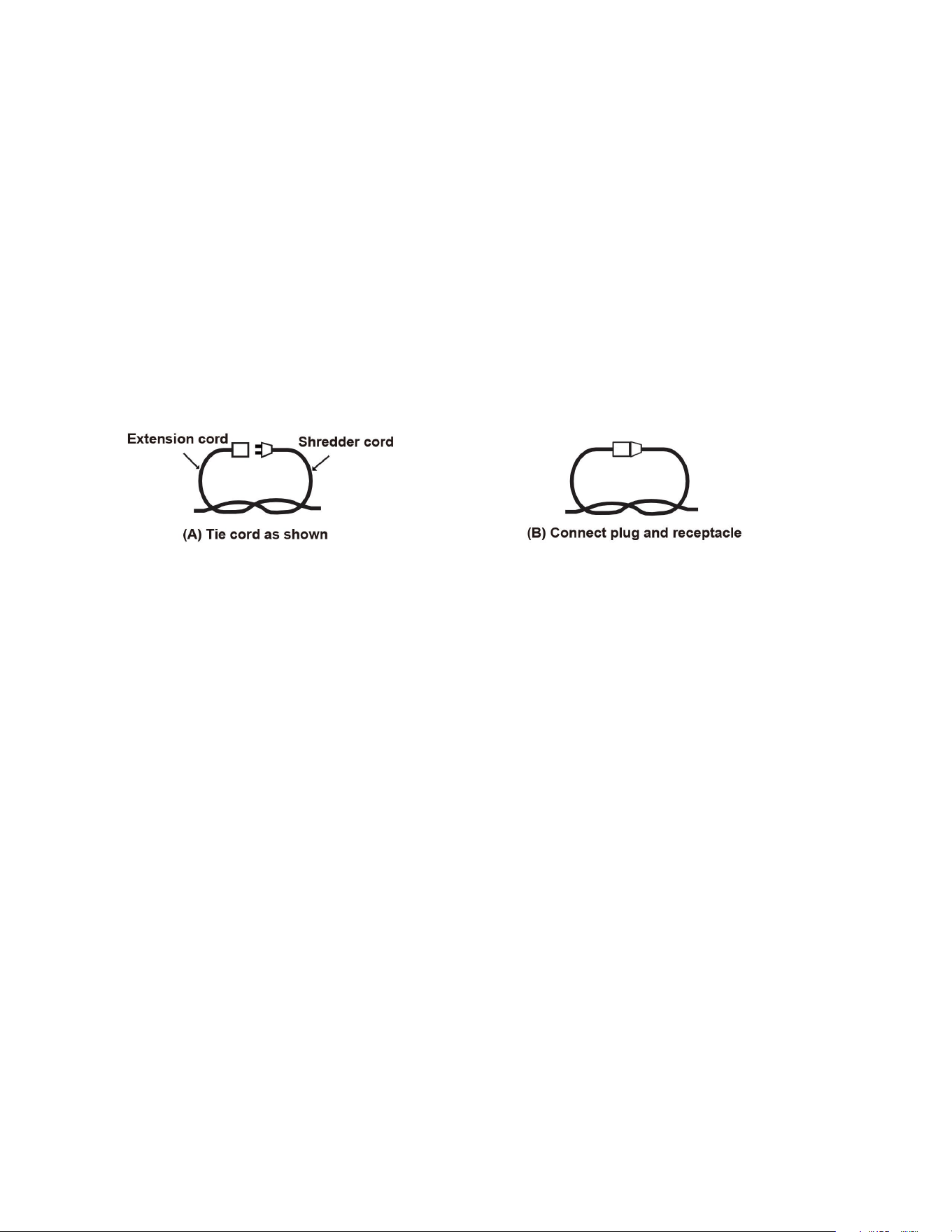
overheating. To reduce the risk of disconnection of appliance cord from the extension cord during use:
i) make a knot as shown in below.
ii) Use one of the plug-receptacle retaining straps or connectors described in this manual.
Avoid unintentional starting. Do not carry plugged-in appliance with finger on switch. Be sure switch
is off when plugging in.
Do not abuse cord. Never carry appliance by cord or yank it to disconnect from receptacle. Keep cord
away from heat, oil, and sharp edges.
Do not force appliance. It will do the job better and with less likelihood of a risk of injury at the rate
for which it was designed.
Do not overreach. Keep proper footing and balance at all times.
Stay alert. Watch what you are doing. Use common sense. Do not operate appliance when you are
tired.
Disconnect the appliance from the power supply when not in use or before servicing.
Keep guards in place and in working order.
Keep blades sharp.
Keep hands and feet away from cutting area.
Power Tool Use And Care
Do not force the power tool. Use the correct power tool for your application. The correct power tool
will do the job better and safer at the rate for which it was designed
Do not use the power tool if the switch does not turn it on and off. Any power tool that cannot be
controlled with the switch is dangerous and must be repaired.
Disconnect the plug from the power source and/or remove the battery pack, if detachable, from the
power tool before making any adjustments, changing accessories, or storing power tools. Such
preventive safety measures reduce the risk of starting the power tool accidentally.
Store idle power tools out of the reach of children and do not allow persons unfamiliar with the power
tool or these instructions to operate the power tool. Power tools are dangerous in the hands of
untrained users.

8
Maintain power tools and accessories with care. Check for misalignment or binding of moving parts,
breakage of parts and any other condition that may affect the power tool's operation. If damaged, have
the power tool repaired before use. Many accidents are caused by poorly maintained power tools.
Keep cutting tools sharp and clean. Properly maintained cutting tools with sharp cutting edges are
less likely to bind and are easier to control.
Use the power tool, accessories and tool bits etc. in accordance with these instructions, taking into
account the working conditions and the work to be performed. Use of the power tool for operations
different from those intended could result in a hazardous situation.
Keep handles and grasping surfaces dry, clean and free from oil and grease. Slippery handles and
grasping surfaces do not allow safe handling and control of the tool in unexpected situations.
Service
Have your power tool serviced by a qualified repair person using only identical replacement parts. This
will ensure that the safety of the power tools maintained.

9
SPECIFIC SAFETY RULES FOR LOG SPLITTER
WARNING: Do not operate your log splitter until it is completely assembled and installed
according to the instructions.
IF YOU ARE NOT thoroughly familiar with the operation of the log splitter, obtain instruction from
a qualified person.
MAKE SURE wiring codes and recommended electrical connections are followed. When servicing,
use only identical replacement parts. Disconnect log splitter from the power source before making
adjustments or repairs.
Place the log splitter on a stable, flat, and level work surface where there is plenty of room for
handling logs.
INSPECT THE LOG SPLITTER before each use. Keep guards in place and in working order. Re
place damaged, missing, or failed parts before using.
Do not alter the log splitter. Altering the tool or exceeding its design capabilities and capacities could
result in serious injury or fatality and will void the warranty.
MAKE SURE THE EXTENSION CORD is no longer than 25 ft.,14 gauge. Ensure the power cord is
rated for outdoor use. Ground the log splitter and avoid contact with grounded surfaces during
operation. See “Electrical Information” for further details.
MAKE all adjustments with the switch in the OFF position and the log splitter disconnected from the
power source.
Never use the log splitter for any other purpose than splitting wood. Any other use can result in injury.
Use extreme caution at all times.
PREPARE LOGS FOR SPLITTING. Make sure the ends of the logs are cut square. Cut off any
branches flush with the trunk.
INSPECT EACH LOG before splitting. Make sure there are no nails or foreign objects in the log.
Only a single operator should load and operate the log splitter. Keep all others, including children and
pets, a minimum of 20 in. (6.1 m) away from the work area.
NEVER TRY TO SPLIT LOGS larger than the rated capacity of the tool. Attempting to do so could
result in personal injury and damage to the tool.
Split only one log at a time. Do not attempt to split two logs on top of each other.
DO NOT put your hands or feet between the log and the splitting wedge or between the log and the
push rod while the tool is in operation.
WARNING: KEEP HANDS AWAY FROM SPLITS AND CRACKS WHICH OPEN IN
THE LOG. THEY MAY CLOSE SUDDENLY AND CRUSH OR AMPUTATE YOUR
HANDS.
Do not attempt to load a log while the push rod is in motion. When loading, place your hands on the
sides of the log, not on the ends.
WAIT FOR THE PUSH ROD TO STOP MOVING before loading another log onto the log splitter.
Do not try to remove a split log until the entire splitting cycle is completed.
Use only your hands to operate the control lever. Never use your foot, knee, rope, or extension device.
Never use your hands to remove a jammed log. If a jam should occur, release the ON/OFF push
button. Follow the instructions in this manual for removing a jammed log.
Stack logs as you work. This will provide a safer, less cluttered work area.
10
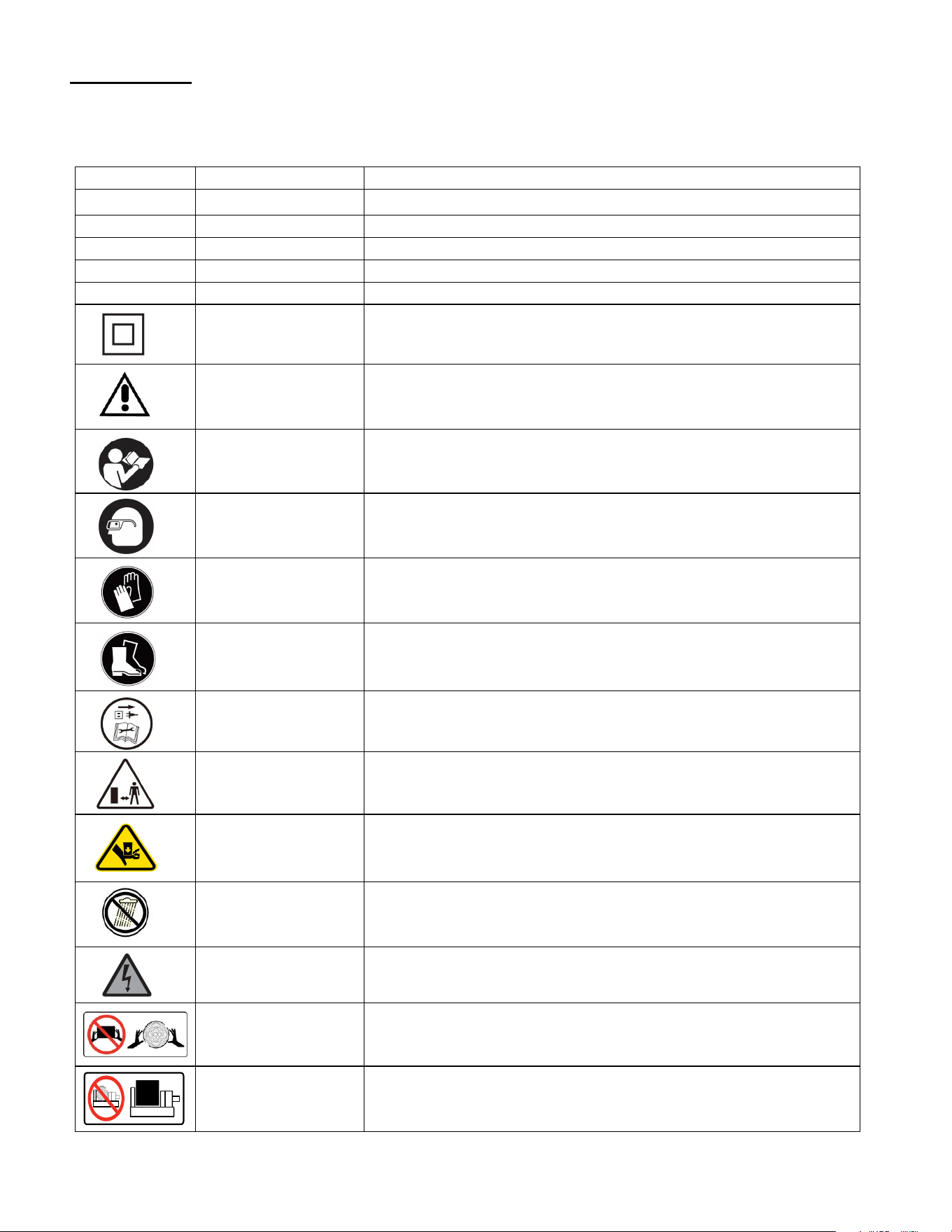
SYMBOLS
Some of the following symbols may be used on this product. Please study them and learn their meaning.
Proper interpretation of these symbols will allow you to operate the product better and safer.
SYMBOL
NAME
DESIGNATION/EXPLANATION
V
Volts
Voltage
A
Amperes
Current
Hz
Hertz
Frequency (cycles per second)
W
Watts
Power
MIN
Minutes
Time
Double Insulation
Class II construction Double Insulated construction.
Safety Alert
Precautions that involve your safety.
Read the user’s
manual
To reduce the risk of injury, user must read and understand
user’s manual before using this product.
Eye and hearing
protection
For protection against injury, wear ear defenders and safety
goggles.
Wear protective
gloves
Wear protective gloves when using the machine and handling
debris.
Protective
,
slip-resistant
footwear
Wear protective,slip-resistant footwear when operating this
equipment.
SWITCH OFF!
Remove plug from outlet before cleaning or conducting
maintenance checks.
Keep bystanders
away
Keep bystanders a safe distance away from the work area.
Keep hands away
Always keep hands away from the wedge and the ram. Moving
parts can crush or cut.
Wet conditions alert
Do not expose to rain or use in damp locations.
Electric shock alert
Beware of electric shock hazard.
Hold logs direction
Hold logs on sides when loading. Keep hands and feet away
from cylinder, wedge, and partially split logs.
Do not split logs
against the grain
Never place hands or any part of the body between a log and any
part of the log splitter. Do not split logs against the grain. Split
logs end to end in the direction of the grain only.
11
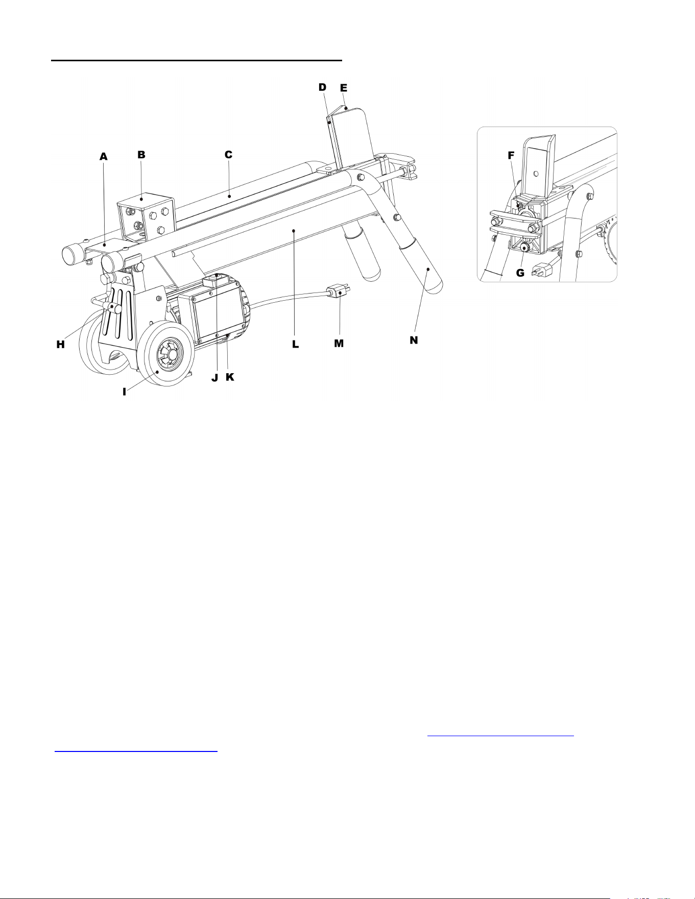
KNOWING YOUR LOG SPLITTER
Unpacking
Unpack the power tool and all its parts, and compare against the list below. Do not discard the carton or
Including
Log Splitter / User Manual
A
Safety guard for 2-hand operating hydraulic control lever
B
Log pusher
C
Log cradle
D
Splitting wedge
E
Rear of wedge
F
Bleeding screw
G
Fluid fill & drain location with dipstick
H
Hydraulic control lever
I
Wheel
J
ON/OFF push switch
K
Circuit breaker
L
Oil tank
M
Plug
N
Carrying handle
12
OPERATING INSTRUCTION
WARNING: Read and thoroughly understand all instructions and safety information before
operating this log splitter. Failure to do so may cause serious injury or death. Do not allow
anyone to operate this log splitter who has not read this manual.
WARNING:
Always wear safety glasses, safety gloves, safety shoes and suitable work clothing when operating
this log splitter. Do not wear jewelry, neckties or other loose clothing which could get caught in
moving parts.
Keep hands and feet clear of the ram and wedge at all times.
Do not start or operate this machine in the presence of flammable liquids or gases.
Before Operating
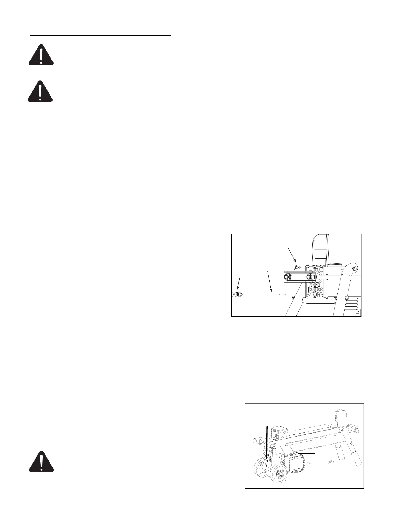
Check the hydraulic fluid level
Before operating, select a suitable work area and check the level of hydraulic fluid. A safe work area will
contain a flat surface on which to place the log splitter, as well as ample room to stack both split and
unsplit logs. Make sure there is a safe electrical connection no more than 25 feet from the workspace.
1. Make sure the bleed screw is closed.
2. Lift up on the handle of the log splitter. Make sure the
splitter is resting securely and will not fall.
3. Unscrew the fluid drain bolt with hex wrench and pull out
the dipstick.
4. Wipe the fluid off the dipstick.
5. Put the dipstick back in the fluid tank and then pull it out
again to check the fluid level. It should be between the two
notches near the end of the dipstick.
6. Add fluid if needed.
7. Screw the fluid drain bolt back tightly.
NOTE: Remember to use AW32 fluid for operation at temperatures above 40 degrees Farenheit, and
automatic transmission fluid for operation below 40 degrees Farenheit. The Log Splitter is pre-loaded
with AW32 fluid during the manufacturing process.
Operating
The Log Splitter requires the use of both hands to operate. The
user’s left hand controls the hydraulic control lever, while the right
hand controls the push button switch. The log splitter will freeze
upon absence of either hand. The log pusher will return back to the
starting position only after both hands release the controls.
WARNING: Split the log in the direction of its grain.
Placing logs across the log splitter for splitting is
dangerous and may seriously damage the machine. Do not attempt
ON/OFF
Push switch
hydraulic control
lever
Fluid
drain
bolt
Dipstick
Bleed screw
13
to split two logs at the same time.
1. Place the log splitter on a flat, stable surface. Make sure there is sufficient room for the unsplit logs and
for the stacks of split logs. Make sure there is a safe electrical connection no more than 25 ft. from the
work area.
2. Loosen the bleed screw counter-clockwise 3~4 turns to allow air to be released from the hydraul
system.
NOTE: Always loosen the bleed screw prior to operation. This will remove any air trapped in the
hydraulic system. Failure to release air from the hydraulic system may damage the seals and
permanently damage the log splitter.
3. Place a properly prepared log firmly on the worktable between the two worktable guards. The log
should fit between the push rod and the splitting wedge.
NOTE: Make sure there are no nails or foreign objects in the log; The end of each log to be split is
square; Remove any branches by cutting them flush with the trunk; Make sure each log is no longer
than 20inch and the diameter is 10inch or less.
4. Depress and hold the ON/OFF push button with your right hand and allow the motor to cycle up to
speed.
5. Push down on the hydraulic lever.
6. Release the ON/OFF push button and the lever when the log is split. The push rod will retract.
WARNING: If the log does not begin to split after 5seconds of operation, release both controls.
The motor or hydraulic fluid may overheat and damage the machine.
Remove a Jammed Log
1. Release the ON/OFF push button and the hydraulic lever to turn off the power and retract the push
rod.
2. Insert a wooden wedge under the jammed log.
3. Activate the push button and the hydraulic lever to start the log splitter and push the wedge under the
log.
4. Release both controls when the log is freed, or when the log is at the height of the wooden wedge.
5. Repeat steps 3 through 4 until the log is freed.
WARNING:
Do not attempt to remove a jammed log with your hand or try to knock it off the worktable. Doing so
may cause injury and may also damage the splitting wedge.
Never try to split logs larger than the rated capacity of the log splitter. Attempting to do so could
result in personal injury and damage to the log splitter.
Never force pressure on the log splitter for more than 5 seconds in order to split excessively hard
wood.
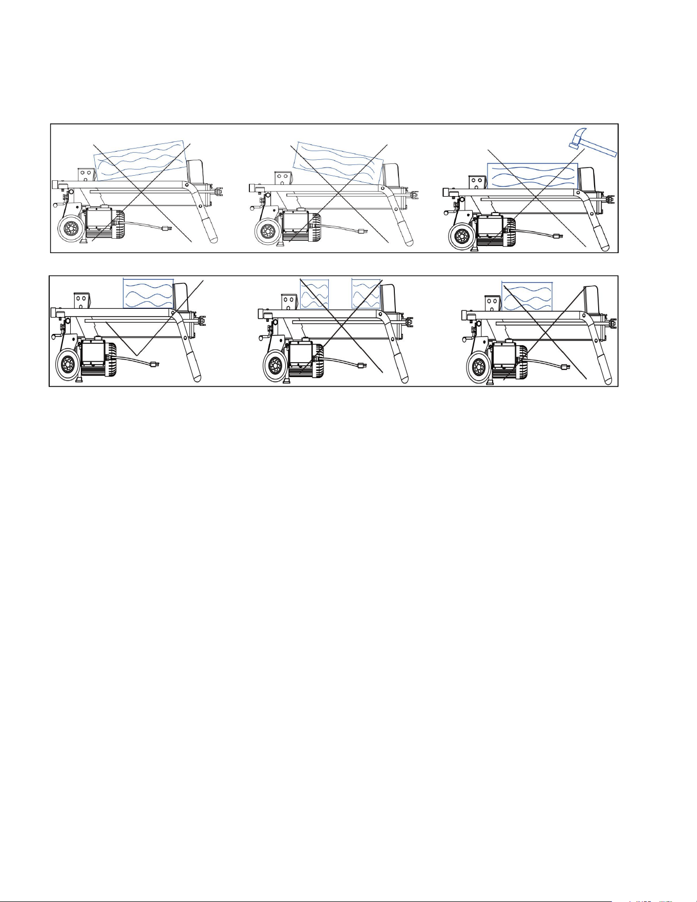
14
Never place hands or feet between log and splitting wedge or between log and ram during forward or
reverse stroke.
Keep clear of moving parts.
Do not attempt to split more than one log at one time!
15
MAINTENANCE
WARNING: Lifting the log splitter is a two person operation. Once raised, make sure the log
splitter is stable before performing any maintenance.
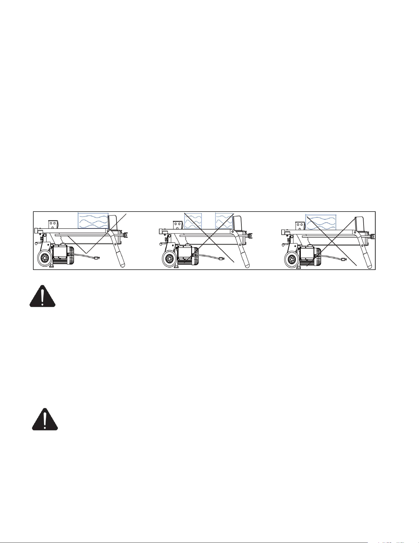
Replace Hydraulic Fluid
WARNING: Replace the hydraulic fluid in the log splitter after every 150 hours of use. Take
the following steps to replace the oil.
1. Make sure all moving parts are stopped and the log splitter is unplugged.
2. Make sure the bleed screw is closed tightly.
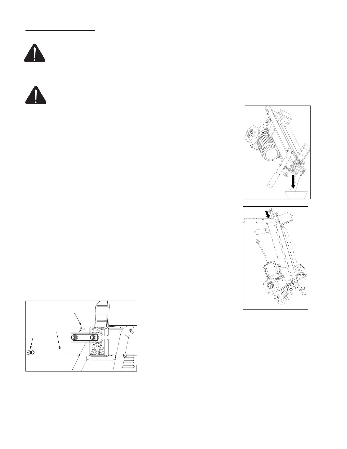
3. Lift up on the handle of the log splitter. Make sure the splitter is resting
securely and will not fall.
4. Use the hex wrench to loosen the fluid drain bolt. Pull out the bolt with
attached dipstick.
5. Turn the log splitter on the support leg side over using a one gallon or larger
capacity container to drain the hydraulic oil as shown in figure 1.
6. Turn the log splitter on the motor side, refill with 3.2 quarts of fresh
hydraulic oil as shown in figure 2.
7. While keeping the log splitter vertical, clean the surface of dipstick on
the fluid drain bolt and put it back into the oil tank. Make sure the level
of the refilled oil is between the two grooves around the dipstick as shown
in figure 3.
8. Clean the oil drain bolt before re-threading it back in. Make sure the bolt is
tightened to avoid leakage before placing the log splitter horizontally.
Sharpening Wedge
When the log splitter wedge becomes dull and/or worn, sharpen the wedge using a fine-toothed file and
smooth any burrs or crushed areas along the cutting edge.
Figure 1
Fluid
drain
bolt
Dipstick
Bleed screw
Figure 2
Figure 3

16
TROUBLESHOOTING
Problem
Cause
Action
Logs will not split
Extension cord is too long or
gauge is too low.
Check extension cord to ensure the
gauge of the cord is 10 or 12 AWG
and that the cord length does not
exceed 25 ft.
Incorrect positioning of the log.
Make sure the log is properly
positioned on the worktable.
The size or hardness or density
of the log may exceed the
capacity of the log splitter.
Reduce the log size before placing it
on the log splitter.
Splitting wedge cutting edge is
blunt or dull.
Sharpen the wedge.
The bleed screw was not
loosened and air is trapped in
the hydraulic tank.
Loosen the bleed screw three or four
turns.
The hydraulic fluid is low and
may need to be replenished.
Check the hydraulic fluid level.
The maximum pressure
limiting adjustment setting has
changed.
Contact customer service
(872)314-0005.
Hydraulic fluid leaks
The bleed screw may not have
been tightened before
transporting the splitter.
Tighten the bleed screw.
The bleed screw may not have
been loosened before operation
and air is trapped in the
hydraulic system.
Loosen the bleed screw three to four
turns.
The fluid drain bolt may be
loose.
Use the hex wrench to tighten the bolt.
The hydraulic control valve
assembly and/or seals may be
worn.
Contact customer service
(872)314-0005.
Push rod movement is
jerky, makes
unfamiliar noise or
vibration.
The hydraulic fluid level may
be low.
Check the fluid level and refill if
needed.
There may be air in the
hydraulic system.
Loosen the bleed screw one or two
rotations.
17
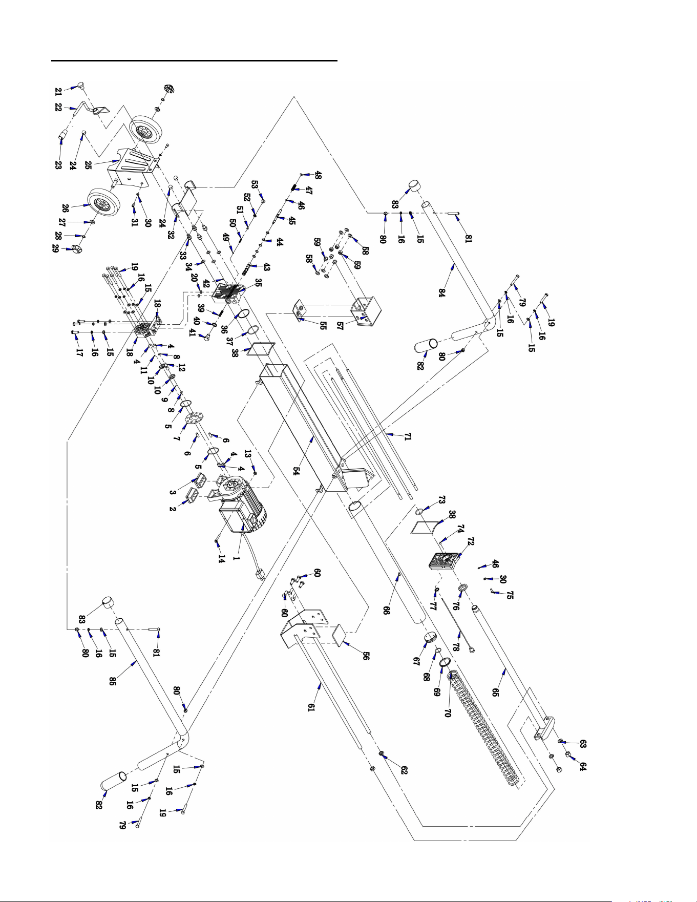
EXPLODED VIEW & PARTS LIST

18
Item
Stock #
Description
Qty
Item
Stock #
Description
Qty
1
BF06-02002
Motor
1
44
GB 3452.1-92
Oil seal 10.6x1.8
5
2
BF06-02009
motor foot cover R
1
45
BF06-01300-REV1
Journey valve
1
3
BF06-02008
motor foot cover L
1
46
GB 3452.1-92
Oil seal 5.6x1.8
2
4
GB12613-90
bearing bush
4
47
BF06-01007
Spring
1
5
GB/T3452.1
Oil seal 46x2.4
2
48
GB/T 896-86
E-ring
1
6
BF06-02001
locating pin
2
49
BG308-2002
steel ball
1
7
BF06-02004
Clapboard
1
50
BF06-01011REV1
Adjustment spring
1
8
GB/T895.2
Steel ring 11
2
51
GB/T 77-2000
Bolt M8×6
1
9
GB308-2000
Steel ball 2.5
1
52
JB982-77
washer 8
1
10
BF06-02006
Gear 5.3
2
53
GB 2672-86
Bolt M8×10
1
11
GB/T119-2000
cylinder pin
1
54
BF07B-01000
Cylinder body
1
12
BF06-02005
Gear shaft
1
55
BF06-01020
Upper pad
1
13
GB/T 6183.1-2000
Locked nut M6
1
56
BF06-01019
Down pad
1
14
GB/T5789-86
Bolt M6x40
1
57
BF06-01600-REV2
stop head
1
15
GB/T 95-2002
Flat washer 8
15
58
GB/T 95-2002
Flat washer 10
6
16
GB/T 93-1987
Spring washer 8
15
59
GB/T 889.1-2000
Nut M10
6
17
GB/T 5783-2000
Bolt M8×30
3
60
GB/T 5781-2000
Bolt M10×25
6
18
BF06-02007
Pump cover
connection seat
1
61
BF06-01200-REV1
Worktable guard
1
19
GB/T 5780-2000
Bolt M8×50
8
62
GB/T 6172.1-2000
thin Nut M14
2
20
GB/T3452.1
Oil seal 10x2.4
2
63
GB/T 93-1987
Spring washer 14
2
21
BF06-01010-REV1
Bolt
1
64
GB/T55-2000
thick Nut M14
2
22
BF06B-02009
Hydraulic control
lever
1
65
BF07-01400-REV1
Push rod
1
23
BF06-01012
plastic handle
1
66
BF07-01014
Cylinder
1
24
GB 923-88
Nut M10
3
67
ELS106H-01004
Piston
1
25
ELS106D-01200
Rear support
1
68
GB3452.1-2005
Oil seal 23.6x2.65
1
26
BF06-00003
6" wheel
2
69
GB/T15242.1
Oil seal TF05500
1
27
GB/T 95-2002
Flat washer 12
2
70
BF07-01016
reset Spring
1
28
GB 894.1-86
Spring washer 12
2
71
BF06B-00006
Stud 06B
4
29
BF06-0003.1
wheel cover
2
72
BF07-01017-REV2
Front cover
1
30
GB/T 95-2002
Flat washer 6
3
73
GB 3452.1-92
Oil seal 30X3.55
1
31
GB/T 70.1-2000
nut M6X12
2
74
BF06-01009
felt
1
32
BF06B-02004
Connect plate
1
75
BF06-01018
Bolt M6x16
1
33
ELS106H-01001
double-headed
Stud
4
76
DH30-38
J ring 30X42X5/10
1
34
ELS106H-01002
copper washer 10
4
77
JB982-77
washer 14
1
35
BF07A-01005-RE
V1
manifold block
1
78
BF06-01500
Dipstick
1
36
ELS106H-01006
retainer ring
1
79
GB/T 5780-2000
Bolt M8×55
2
37
GB3452.1-2002
Oil seal 49.4X3.1
1
80
GB/T889.1-2000
Nut M8
4
38
BF06-01002
rubber washer
2
81
GB/T 70.2-2000
round head Bolt
M8×55
2
39
BF06-01004
spring
1
82
BF06B-00010
Rubber foot
2
40
JB982-77
washer 16
1
83
BF06B-00003
Rear support cover
2
41
BF06-01003
valve bolt
1
84
BF06B-02002
Rear support L
1
42
GB/T78-2000
Bolt M4x6
1
85
BF06B-02003
Rear support R
1
43
BF06-01008REV1
Control valve
1

19
TWO (2) YEARS LIMITED WARRANTY
PowerSmart
®
is committed to building tools that are dependable for years. Our warranties are consistent with our
commitment and dedication to quality.
TWO (2) YEARS LIMITED WARRANTY OF POWER SMART PRODUCTS FOR HOME USE.
PowerSmart (“Seller") warrants to the original purchaser only, that all PowerSmart consumer power tools will be
free from defects in material or workmanship for a period of two (2) years from date of purchase. Ninety (90) days
for all Power Smart Products, if the tool is used for professional or commercial use.
SELLER’S SOLE OBLIGATION AND YOUR EXCLUSIVE REMEDY under this Two (2) Years Limited
Warranty and, to the extent permitted by law, any warranty or condition implied by law, shall be the repair or
replacement of parts, without charge, which are defective in material or workmanship and which have not been
misused, carelessly handled, or misrepaired by persons other than Seller or Authorized Service Center. To make a
claim under this Limited Warranty, you must return the entire power tool product; transportation prepaid, to Power
Smart Include a legible copy of the original receipt, which lists the date of purchase (month and year) and the name
of the company purchased from.
THIS LIMITED WARRANTY DOES NOT APPLY TO ANY ACCESSORY ITEMS INCLUDED WITH THE
TOOL SUCH AS CIRCULAR SAW BLADES OTHER RELATED ITEMS OR TO ANY REPLACEMENT
PARTS LISTED UNDER MAINTENANCE.
ANY IMPLIED WARRANTIES SHALL BE LIMITED IN DURATION TO TWO (2) YEARS FROM DATE OF
PURCHASE. SOME STATES IN THE U.S. AND SOME CANADIAN PROVINCES DO NOT ALLOW
LIMITATIONS ON HOW LONG AN IMPLIED WARRANTY LASTS, SO THE ABOVE LIMITATION MAY
NOT APPLY TO YOU.
IN NO EVENT SHALL SELLER BE LIABLE FOR ANY INCIDENTAL OR CONSEQUENTIAL DAMAGES
(INCLUDING BUT NOT LIMITED TO LIABILITY FOR LOSS OF PROFITS) ARISING FROM THE SALE
OR USE OF THIS PRODUCT. SOME STATES IN THE U.S. AND SOME CANADIAN PROVINCES DO NOT
ALLOW THE EXCLUSION OR LIMITATION OF INCIDENTAL OR CONSEQUENTIAL DAMAGES, SO
THE ABOVE LIMITATION OR EXCLUSION MAY NOT APPLY TO YOU.
THIS LIMITED WARRANTY GIVES YOU SPECIFIC LEGAL RIGHTS, AND YOU MAY ALSO HAVE
OTHER RIGHTS WHICH VARY FROM STATE TO STATE IN THE U.S., PROVINCE TO PROVINCE IN
CANADA AND FROM COUNTRY TO COUNTRY.
For questions / comments, technical assistance or repair parts –
Please call toll free at: 1-872-314-0005 (M-F 9am – 5pm EST)
SAVE YOUR RECEIPTS. THIS WARRANTY IS VOID WITHOUT THEM.

20

21

22