

PREFACE
Thank you very much for choosing our Multi-Band Amateur Radio in favor of our products.
This Amateur radios utilizes the latest advanced technology to provide reliable communications in today's demanding communications
environments. It is extremely stable and reliable for long distance communication with a sleek and compact design. It features emergency
alarm, personnel death alarm, work alone, GPS, APRS position reporting, analog DTMF, 2TONE, 5TONE, CTCSS/DCS encode/decode.
Whether you are a professional who needs to keep in touch with your active team (such as ranching, farming, driving, hunting, forest
protection, tactical training) or a recreational user who just wants to keep in touch with friends and family, this product will surely bring you
all kinds of convenience in your work, life and leisure.
To avoid personal injury or property damage caused by improper operation, please read all information carefully before using our products.
To ensure that you maximize the convenience of this product, please read this manual and the Safety Information Manual before use.
WARNING: MODIFICATION OF THIS DEVICE TO RECEIVE CELLULAR RADIOTELEPHONE
SERVICE SIGNALS IS PROHIBIITED UNDER FCC RULES AND FEDERRAL LAW.
ATTENTION!
When programming the radio, start by reading the factory software data, and then rewrite this data with your
frequency etc., to a new saved code plug, otherwise errors may occur. You can use the programming cable with a PC to program
the authorized frequency, bandwidth, power, etc. your programming must comply with your FCC (or EU other country) license
certification.
ATTENTION!
Before using this product, read the RF Energy Exposure and Product Safety Guide that ship with the radio which
contains instructions for safe usage and RF energy awareness and control for compliance with applicable standards and
regulation.
FRS, GMRS, MURS, PMR446
You may be tempted to use FRS, GMRS, MURS (in the USA) or PMR446 (in Europe) frequencies. Do note however that there are
restrictions on these bands that make this transceiver illegal for use.

Chapter 1. Getting Started
1.1 Regulations and Safety Warnings
FCC Regulatory Conformance
This equipment has been tested and found to comply with the limits for a Class B digital device, pursuant to Part 15 of FCC Rules. These limits
are designed to provide reasonable protection against harmful interference in a residential installation. This equipment generates and can
radiate radio frequency energy. If not installed and used in accordance with the instructions, it may cause harmful interference to radio
communications. However, there is no guarantee that interference will not occur in a particular installation. Verification of harmful interference
by this equipment to radio or television reception can be determined by turning it off and then on. The user is encouraged to try to correct the
interference by one or more of the following measures:
- Reorient or relocate the receiving antenna.
- Increase the separation between the equipment and receiver.
- Connect the equipment into an outlet on a circuit different from that to which the receiver is connected.
- Consult the dealer or an experienced radio/TV technician for help.
Changes or modifications not expressly approved by the party responsible for compliance could void the user's authority to operate the
equipment.
This device complies with Part 15 of the FCC Rules. Operation is subject to the condition that this device does not cause harmful interference.
WARNING
!
MODIFICATION OF THIS DEVICE TO RECEIVE CELLULAR RADIOTELEPHONE SERVICE SIGNALS IS PROHIBIITED
UNDER FCC RULES AND FEDERRAL LAW.
Compliance with RF Exposure Standards
The radio complies with the following RF energy exposure standards and guidelines:
• United States Federal Communications Commission, Code of Federal Regulations; 47 CFR § 1.1307, 1.1310 and 2.1093
• American National Standards Institute (ANSI) / Institute of Electrical and Electronic Engineers (IEEE) C95.1:2005; Canada RSS102 Issue 5 March
2015
• Institute of Electrical and Electronic Engineers (IEEE) C95.1:2005 Edition

RF Exposure Compliance and Control
Guidelines and Operating Instructions
To control your exposure and ensure compliance with the occupational/ controlled environmental exposure limits, always adhere to the
following procedures.
Guidelines:
• Do not remove the RF Exposure Label from the device.
• User awareness instructions should accompany device when transferred to other users.
• Do not use this device if the operational requirements described herein are not met.
Operating Instructions:
• Transmit no more than the rated duty factor of 50% of the time. To transmit (talk), press the Push-to-Talk (PTT) key. To receive calls, release
the [PTT] key. Transmitting 50% of the time, or less, is important because the radio generates measurable RF energy only when transmitting
(in terms of measuring for standards compliance).
• Keep the radio unit at least 2.5cm away from the face. Keeping the radio at the proper distance is important as RF exposure decreases with
distance from the antenna. The antenna should be kept away from the face and eyes.
• When worn on the body, always place the radio in an approved holder, holster, case, or body harness or by use of the correct clip for this
product. Use of non-approved accessories may result in exposure levels which exceed the FCC's occupational/ controlled environmental RF
exposure limits.
• Use of non-approved antennas, batteries, and accessories causes the radio to exceed the FCC RF exposure guidelines.
• Contact your local dealer for the product's optional accessories.
■Precautions for Portable Terminals
Operating Prohibitions
To protect you against any property loss, bodily injury or even death, be sure to observe the following safety instructions:
1. Do not operate the product in a location containing fuels, chemicals, explosive atmospheres and other flammable or explosive materials. In
such location, only an approved Ex-protection model is allowed for use, but any attempt to assemble or disassemble it is strictly prohibited.
2. Do not operate the product near or in any blasting area.

3. Do not operate the product near any medical or electronic equipment that is vulnerable to RF signals.
4. Do not hold the product while driving.
5. Do not operate the product in any area where use of wireless communication equipment is completely prohibited.
Important Tips
To help you make better use of the product, be sure to observe the following instructions:
1. Do not use any unauthorized or damaged accessory.
2. Keep the product at least 2.5 centimeters away from your body during transmission.
3. Do not keep the product receiving at high volume for a long time.
4. For vehicles with an air bag, do not place the product in the area over the air bag or in the air bag deployment area.
5. Keep the product and its accessories out of reach of children and pets.
6. Please operate the product within the specified temperature range.
7. Continuous transmission for a long time may lead to heat accumulation within the product. In this case, please keep it at a proper location
for cooling.
8. Handle the product with care.
9. Do not disassemble, modify or repair the product and its accessories without authorization.
■
Precautions for Batteries
Charging Prohibitions
To protect you against any property loss, bodily injury or even death, be sure to observe the following safety instructions:
1. Do not charge or replace your battery in a location containing fuels, chemicals, explosive atmospheres and other flammable or explosive
materials.
2. Do not charge your battery that is wet. Please dry it with a soft and clean cloth prior to charge.
3. Do not charge your battery suffering deformation, leakage and overheat.
4. Do not charge your battery with an unauthorized charger.
5. Do not charge your battery in a location where strong radiation is present.

6. Overcharge shall always be prohibited for it may shorten the life of your battery.
Maintenance Instructions
To help your battery work normally or prolong its life, be sure to observe the following instructions:
1. Accumulated dust on charging connector may affect normal charging. Please use a clean and dry cloth to wipe it on a regular basis.
2. It is recommended to charge the battery under 5℃~40℃. Violation of the said limit may cause battery life reduction or even battery
leakage.
3. To charge a battery attached to the product, turn it off to ensure a full charge.
4. Do not remove the battery or unplug the power cord during charging to ensure a smooth charging process.
5. Do not dispose of the battery in fire.
6. Do not expose the battery to direct sunlight for a long time nor place it close to other heating sources.
7. Do not squeeze and penetrate the battery, nor remove its housing.
Transportation Instructions
1. Damaged batteries must not be transported.
2. To avoid short circuit, separate the battery from metal pars or from each other if two or more batteries are transported in one packaging.
3. The radio must be switched off and secured against switch-on, if the battery is attached.
The content of the shipment must be declared in the shipping documents and by a Battery Shipping Label on the packaging. Contact your hauler
for the local regulations and further information.
1.2 Content of the packaging
This transceiver comes shipped with the following items in the box:
• 1 Radio body • 1 Belt Clip • 1 Antenna
• 1 Lithium-Ion battery pack • 1 Desk charger (With wall-wart) • 1 Wrist Belt
• Instruction Manual
*If any item is missing, please notify your Baofeng / Pofung dealer.

1.3 Features and Functions
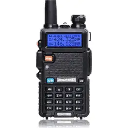
• 1.77" TFT large screen, full keyboard, fully open menu operation
• Scanner function: VFO scan range setting, three scan recovery methods, channel scan, CTC/DCS scan, scan channel
addition and removal
• 108-136,136-174,220-260,350-390,400-520MHz Multiband scanning receiver (*Suitable for North American users)
*144-146MHz, 430-440MHz (Applicable to users in EU countries and regions)
• Built-in input method, allows this device to edit channel name
• NOAA Weather Radio Channel Reception in the United States and Canada
• Frequency step, selectable between 2.5K | 5.0K | 6.25K | 10.0K | 12.5K | 20.0K | 25.0K | 50.0K
• Type-C direct charging and charging stand, more convenient battery life
• Dual-band handheld transceiver. • DTMF encoder and DTMF manual dial
• High Capacity Lithium-Ion battery. • Broadcast FM radio receiver 87.5-108 MHz
• 50 CTCSS tones and 105 DCS codes. • VOX (voice activated transmit).
• 10 zones storage, Up to 640 named memory channels. • Alarm function.
• High or low power selectable. • Display illumination programmable via keypad.
• Function beep on the keyboard. • Dual watch / Dual reception.
• Programmable repeater offset. • Battery saving function.
• Transmission time-out timer. • Scan mode.
• Busy channel lock out. • Built in CTCSS/DCS tones.
• Ten (10) levels of Squelch adjustment. • Cross band reception.
• End of transmission tone, aka “Roger Beep”. • One touch search frequency
• Two (2) pins for Kenwood accessory port • Analog signaling DTMF, 2TONE, 5TONE, BDC1200 codecs
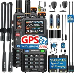
• GPS positioning function, location sharing and requesting location information from others

Chapter 2. Battery Information
2.1 Charging the Battery Pack
The Li-ion battery pack is not charged at the factory; please charge it before use. Charging the battery pack for the first time
after purchase or extended storage (more than 2 months) may not bring the battery pack to its normal maximum operating
capacity. Best operation will require fully charging/ discharging the battery two or three times before the operating capacity
will reach its best performance. The battery pack life may be depleted when it’s operating time decreases even though it has
been fully and correctly charged. If this is the case, replace the battery pack.
2.2 Charger Supplied
Please use the specified charger provided by our company. Other models may cause explosion and personal injury. After
installing the battery pack, and if the radio displays low battery with a voice prompt, please charge the battery.
2.3 Use Caution with the Li-ion Battery
a. Do not short the battery terminals or throw the battery into a fire. Never attempt to remove the casing from the battery
pack, as our company cannot be held responsible for any accident caused by modifying the battery.
b. The ambient temperature should be between 5ȭ-40ȭ (40˚F - 105˚F) while charging the battery. Charging outside this
range may not fully charge the battery.
c. Please turn off the radio before inserting it into the charger. It may otherwise interfere with correct charging.
d. To avoid interfering with the charging cycle, please do not cut off the power or remove the battery during charging until
the green light is on.
e. Do not recharge the battery pack if it is fully charged. This may shorten the life of the battery pack or damage the battery
pack.
f. Do not charge the battery or the radio if it is damp. Dry it before charging to avoid damage.
WARNING
!
When keys, ornamental chain or other electric metals contact the battery terminal, the battery may become damage or

injure a human. If the battery terminals are short circuited it will generate a lot of heat. Take care when carrying and
using the battery. Remember to put the battery or radio into an insulated container. Do not put it into a metal container.
2.3 How to Charge
a. Plug the AC adaptor into the AC outlet, and then plug the cable of the AC adaptor into the DC jack located on the back of
the charger. The indicator light blinks orange and is then ready to charge a battery.
b. Plug the battery or the radio into the charger. Make sure the battery terminals are good in contact with charging terminals.
The indicator light turns to red--- charging begins.
c. It takes approximately 2-5 hours to fully charge the battery. When the lamp lights green, the charging is completed.
Remove the battery or the radio unit with its battery from socket.
When charging a radio (with battery) the indicating lamp will not turn into green to show the fully charged status if the
radio is powered on. Only when the radio is switched off will the lamp indicate normal operation. The radio consumes
energy when it is power-on, and the charger cannot detect the correct battery voltage when the battery has been fully
charged. So the charger will charge the battery in constant voltage mode and fail to indicate correctly when the battery
has been fully charged.
2.4 How to Store the Battery
a. If the battery needs to be stored, keep it in status of 80% discharged.
b. It should be kept in low temperature and dry environment.
c. Keep it away from hot places and direct sunlight.
» Do not short circuit the battery terminals.
» Never attempt to remove the casing from the battery pack.
» Never store the battery in unsafe surroundings, as a short may cause an explosion.
» Do not put the battery in a hot environment or throw it into a fire, as it may cause an explosion.
2.5 Using the Type-C USB Charger
The Type-C USB charger is a handy port that allows you to conveniently charge your Li-ion battery pack.
1. Make sure your radio is turned OFF.
2. Plug the Type-C USB cable into the Type-C USB charging port on your battery. Connect the other end of the micro-USB
charger to wall power outlet.
3. An empty battery will be fully charged in 4 hours.

4. The battery meter on LCD will move to indicate the battery is charging.
Note:
• It is recommended to power OFF your radio while charging. However, if power is turned on while charging, you may not
be able to transmit a message if the battery is completely empty. Allow time for the battery to charge to 1 bar before
attempting to transmit a message.
• For optimal battery life, remove the radio from the charger within 6 hours. Do not store the radio while connected to the
charger.
Chapter 3. Installation of Accessories
Before the radio is ready for use we need to attach the battery pack, as well as charge the battery.
3.1 Installing/ Removing the Antenna
1). Installing the Antenna: Screw the antenna into the connector on the top of the transceiver by holding the antenna at its
base and turning it clockwise until secure.
2). Removing the Antenna: Turn the antenna counter-clockwise to remove it.
3.2 Installing the belt clip
1). At the back of the radio there are two parallel screws mounted above the battery, remove these and thread them
through the holes on the belt clip as you screw them back into the radio body.
2). Removing the Belt Clip: Unscrew counter-clockwise to remove the belt clip.
3.3 Installing the battery pack
Before attaching or removing the battery make sure your radio is turned off by turning the power/volume knob all the way
counter-clockwise.
1). Make sure the battery is aligned in parallel with the radio body with the lower edge of the battery about 1-2cm below the
edge of the radio.
2). Once aligned with the guide-rails, slide the battery upward until you hear a click as the battery locks in place.
Remove the battery pack
To remove the battery, press the battery release above the battery pack, as you slide the battery downward.
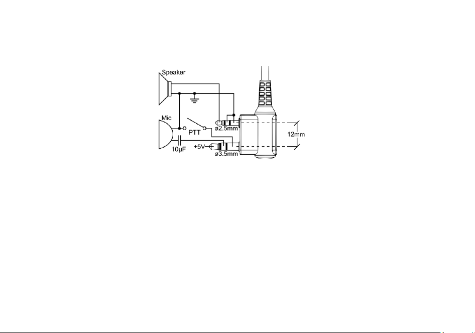
3.4 Installing the Additional Speaker/Microphone (Optional)
Pry open the rubber MIC-Headset jack cover and then insert the Speaker / Microphone plug into the double jack.
Chapter4. Radio Overview
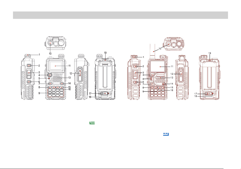
4.1 Bu�ons and controls of the radio
1. Power/Volume knob 2.SK1- Broadcast FM and Alarm key 3. PTT key
4. VFO/MR mode key 5. Status LED 6. SK2-Flashlight and Monitor key
7. A / B select key 8.
Key (MENU) 9. Numeric keypad
10. Antenna jack. 11. Color LCD 12. Accessory jack
13. Speaker and microphone 14. One-Touch search key 15.
Key (EXIT)
16. or naviga�on keys 17. Type-C charging port 18. Type-C charging indicator
19. Ba�ery release latch

4.2 Main keypad controls
ᶈ VFO/MR: Short press to switch VFO/MR mode. Press and hold to switches channel display mode: Channel CH, Frequency (display small
channel number), Name (channel alias).
ᶈ A/B: Short press to switches between A (upper) and B (lower) displays. Press and hold to switch Double Wait /
Signal Wait / Off dual watch
mode.
ᶈ
Sweep: Short press to enter one key sweep.
ᶈ
: Short press to return to the menu or return to the previous menu. Press and hold to quickly enter GPS mode (My Location, valid when
GPS function is turned on)
ᶈ
: Press and hold to lock or unlock the keyboard. In transit mode, short press the key in inverted frequency (display R)\offline (display T)
ᶈ
: Short press to enter DTMF dial. Press and hold to scan on and off.
ᶈ 0[space] : Press and hold to enter weather switch to select weather channel.
4.3 Programmed Key (SK1/SK2)
It is possible to set different functions for [SK1], [SK2] keys.
Method 1: In radio Menu -Radio Setting –Press and Longpress SK1, SK2.
Method 2: In PC software –Buttons.
Option
Functionality
None
No function is assigned to this button.
Scan
To enable or disable the Scan feature.
Monitor
To enable or disable the Monitor feature.
Tou c h
To enable or disable the Tou ch feature.
FM Radio
To enable or disable the FM Radio feature.
SOS
To enable or disable the emergency alarm feature.
GNSS system
To enable or disable the GNSS system feature.
One Touch Search
To enable or disable the One Touch Search feature.
1750Hz
Transmits 1750Hz Tone Burst

BT
To enable or disable the BT feature. The BT earpiece can work properly only after the BT
feature is enabled.
Man Down
To enable or disable the Man Down feature.
One Touch Call
To make a call or send a message to the preset contact or implement an auxiliary feature.
Zone
To Switch between the two zone.
Voltage
Check the current battery capacity voltage
TX Power
Switch the power between super high, high, middle and low power.
VOX
To enable or disable the VOX feature.
Work Alone
Turn on/off the work alone function.
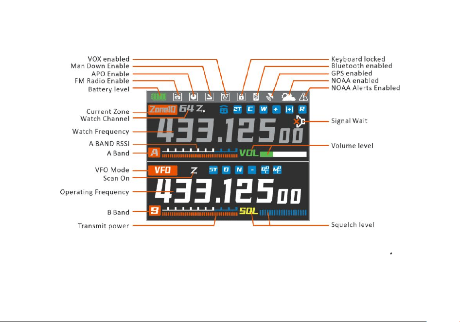
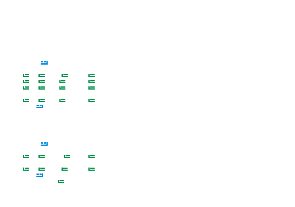
4.5 LCD icon summary
*The highlighted band is the main channel (i.e., the working band) and the grayed-out band is the sub band (the watch band)
。
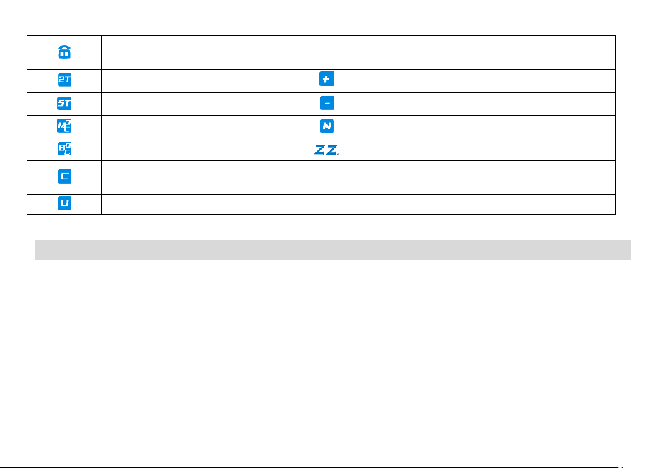
Make sure you can hear the DTMF side
tone from the radio speaker, set to DT-S T,
ANI-ST, DT+ANI.
R
Reverse function enabled
2TONE signaling enabled for current
channel/frequency
Enables access of repeaters in VFO/Frequency Mode. TX
will be shifted higher in frequency than RX。
5TONE signaling enabled for current
channel/frequency
Enables access of repeaters in VFO/Frequency Mode. TX
will be shifted lower in frequency than RX
MDC1200 signaling enabled for current
channel/frequency
Narrowband enabled
BDC1200 signaling enabled for current
channel/frequency
Scan enabled
CTCSS enabled
T
Talkaround has been activated, off grid at the central
turntable. The transmission frequency is equal to the
receive frequency
DCS enabled
Chapter 5. Basic Operations
5.1 Power on the radio
• Turning the unit on
To turn the unit on, simply rotate the Volume/Power knob clockwise until you hear a "click". If your radio powers on correctly there should be
an audible double beep after about one second and the display will show a message or flash the LCD depending on settings for about one
second. Then it will display a frequency or channel. If the Voice prompt is enabled, the voice will announce "frequency mode" or "channel
mode".
• Turning the unit off
Turn the Volume/Power knob counter-clock wise all the way until you hear a "click". The unit is now off.
5.2 Adjusting the volume
To turn up the volume, turn the volume/power knob clock-wise. To turn the volume down, turn the Volume/Power knob counter-clock-wise. Be

careful not to turn it too far, as you may inadvertently turn your radio off.
5.3 Main Band/Sub Band Switch
Press the [A/B] key switches between A (upper) and B (lower) displays. The frequency or channel on the selected display becomes the active
listening and transmit frequency or channel.
NOTE: The highlighted band is the main band and the grey band is the sub band.
5.4 VFO/Channel Switch
Pressing [VFO/MR] key switches between Frequency (VFO) Mode and Memory (MR) mode. Memory mode is sometimes also referred to as
Channel mode.
For everyday use, Channel (MR) mode is going to be a whole lot more practical than Frequency (VFO) mode. However, Frequency (VFO) mode is
very handy for experimentation out in the field. Ultimately which mode you end up using will depend entirely on your use case.
5.5 Frequency (VFO) mode
In Frequency (VFO) mode you can navigate up and down the band by using the or keys. Each press will increment or decrement your
frequency according to the frequency step you've set your transceiver to.
You can also input frequencies directly on your numeric keypad with kilohertz accuracy.
The following example assumes the use of a 12.5 kHz frequency step.
Example. Entering the frequency 436.61250 MHz on display A
(1) In standby mode, press and hold the
key to switch to the frequency (VFO) mode.
(2) Enter [4][3][6][6][1][2][5] [0] on the numeric keypad.
WARNING!
Just because you can program in a channel does not mean you're automatically authorized to use that frequency. Transmitting on
frequencies you're not authorized to operate on is illegal, and in most jurisdictions a serious offence. However, it is legal in most jurisdictions
to listen. Contact your local regulatory body for further information on what laws, rules and regulations apply to your area.
5.6 Channel (MR) mode and Channel selection
Pressing [VFO/MR] key switches between Frequency (VFO) Mode and Memory (MR) mode. select Channel mode.
• Operation 1: Press the or navigation key to select the channel.
• Operation 2: Input the channel numbers by the keyboard. For example, if you want switch to channel 12, input [1][2] a total of 2 digits, and it

will switch to channel 12.
When the voice prompt function is enabled, the corresponding channel will be broadcast by voice.
5.7 Select a Zone
A zone is a group of channels with the same property. The radio supports up to 10 zones, with a maximum of 64 channels per zone. To select a
zone, do one of the following:
Press
key go to Menu > Zone, press or navigation key to select a zone, and then press key to switch to the selected zone.
The corresponding regional alias will be displayed at the bottom of the screen.
5.8 Making a call
NOTE: Press the key to switch the main channel to the other channel if there are 2 channels shown on the display. In standby mode,
press and hold the
key to switch between frequency (VFO) mode and channel (MR) mode.
• Channel mode call: After selecting a channel, hold down the [PTT] key to initiate a call to the current channel. Speak into the microphone with
normal tone. Making a call, the red LED is on.
• Frequency mode call: Press and hold the
key to switch to the frequency mode, input the working frequency within the allowable
frequency range, and press and hold the [PTT] key to transmit on the current frequency. Speak into the microphone with normal tone. Making
a call, the red LED is on.
• Receive a call: When you release the [PTT] key, you can answer it without any action.
When receiving a call, the green LED is on.
NOTE: To ensure the best reception volume, keep the distance between the microphone and the mouth at the time of transmission from 2.5
cm to 5 cm.
5.9 Emergency Alert
The Emergency Alert feature can be used to signal members in your group for help.
To activate the emergency alert function, Press the pre-programmed [Emergency Alarm] key.
Press the pre-programmed [Emergency Alarm] to exit the emergency alert function.
WARNING: The Emergency Alert feature should only be used in the even of an actual emergency.
5.10 FM Radio (FM)

Method 1: Press key go to the main Menu -> Radio Settings -> Press/ Longpress of "SK1/SK2" as [FM Radio], and turn on or off the radio by
pressing the preset [FM Radio] key.
Method 2: Press
key go to the main Menu -> Radio Settings ->Radio On/Off, turn the radio on or off.
After turning on the radio function, the station search method is as follows:
-Press
key to enter radio search mode, the screen displays 'Seeking...', the radio will automatically save the searched radio frequency as a
radio channel (memory mode).
-Press or to select the radio channel.
-Directly input familiar radio frequency by numeric keys (frequency mode, e.g. 96.9MHz, input 969)
-Short press the preset [FM Radio] key or
key to exit the radio mode.
The frequency ranges to listen to the radio is 65-108MHz. When listening to broadcast FM, press
key switches between 65-75 MHz and
76-108 MHz band.
5.11 Radio Interrupt
On: When FM radio is used, you can still receive or transmit on the channel.
Off: When FM radio is used, the radio will not permit a transmission or reception.
5.12 Monitor
In standby, Press the pre-programmed [Monitor] key to enter Monitor. When receiving matched carrier but the signaling or the signal is too
weak, this function allows monitor the weak signal.
Press the pre-programmed [Monitor] key again to turn off the speaker and exit the Monitor mode.
5.13 Keypad lock
The radio features a keypad lock that locks out all keys except for the three side keys.
To enable or disable the keypad lock, press and hold
the key for about two seconds.
You can also enable so that the radio automatically locks the keypad after ten seconds from the menu.
5.14 Frequency reversal
A short momentary press of the key enables the reverse function
If you for some reason want to listen to the repeater's input frequency instead, press
key momentarily and you'll reverse your transmit and
receive frequencies.

5.15 TX Repeaters tone
Ton e -burst 1750Hz, but also 1000Hz, 1450Hz, 2100Hz, these tone-bursts are mainly used for repeater activation and are more common in
Europe.
Before using the Tone-burst function, the SK1/SK2 programmable key must be defined as the “1750Hz” function.
Press the pre-programmed [1750Hz] key to send 1750Hz tone-bursts. This function is useful for communications through repeaters.
5.16 NOAA Weather/ Weather Alert
Your radio has a NOAA Weather Radio function, to enable the user to receive weather reports from designated NOAA stations. Your radio also
has a NOAA Weather Scan function, to enable the user to scan all 10 channels of the NOAA Weather Radio.
Press
key >> NOAA weather >> Weather On/Off. Options:
-Off: NOAA weather forecast function is not enabled.
-WX1 162.550 MHz -WX2 162.400 MHz
-WX3 162.475 MHz -WX4 162.425 MHz
-WX5 162.450 MHz -WX6 162.500 MHz
-WX7 162.525 MHz -WX8 161.650 MHz
-WX9 161.775 MHz -WX10 163.275 MHz
Press or to select a NOAA channel. Enable this channel and display the
icon on the first line
Note: Channels WX 1 through WX10 receive only NOAA and Canadian Weather Radio channels. You cannot transmit on these channels.
Weather Alert
Press the key >>NOAA Weather >> Weather Alert. Options:
-Off: Disables the Weather Alert function. The weather alert
icon is not displayed .
-On: Enables the weather alert function. The weather alert
icon is displayed .
With the Weather Alert feature enabled, the radio returns to standby and is allowed to receive calls. The radio guards the radio channel and
weather channel and automatically cycles through the work channel and weather alert channel.
Activate the Weather Alert feature and receive a 1050 HZ alert signal, you will hear a loud beep and the radio will automatically switch to
weather broadcast mode.
NOAA Weather Shortcuts
In standby mode, press and hold [0] key to quickly enter the NOAA weather menu, press or key to select a weather channel or turn off
NOAA weather.
Press the
key to Weather Alert, press or to select ON or OFF.
Press the
key to return to the radio mode, the screen displays the icon .
5.17 One touch frequency Search
Method 1: Press [MENU] key go to the main Menu -> Radio Settings -> Press/ Longpress of "SK1/SK2" as [OneTouch Search], and enter the
frequency search mode by pressing the preset [OneTouch Search] ke y.
Method 2: Press the
key (green key, OneTouch Search) to enter the frequency search mode.
When using the OneTouch Search function, this unit will act as a receiver.
Press the preset [OneTouch Search] key, the screen will display “Seeking” and the indicator light will be yellow.
Successful seeking will display the search frequency and CTCSS/DCS, and turn on the speaker.
-You can press the
key to save the search frequency and CTCSS/DCS to the channel.
-Press and hold the [PTT] key to make a callback.
Chapter 6. Advanced Features
6.1 Scanner
The radios features a built in scanner for the VHF and UHF bands. When in Frequency (VFO) mode it will scan in steps according to your set
frequency step. In Channel (MR) mode it will scan your channels.
To enable the scanner, press and hold the
key for about two seconds. You can change the scanning direction with the or keys. Press
and hold the
key to exit scanning mode.
6.1.1 Frequency Ranger

In frequency mode, the frequency sweep range can be precisely set. Input the start value and end value of the sweep frequency through the
keyboard.
EX: Enter 144146, in frequency mode, scan in the range of 144.000-146.000MHZ. Enter 430440, in frequency mode, scan in the range of
430.000-440.000MHZ.
Note: for VFO frequency Ranger, see Menu>SCAN>Freq Ranger.
6.1.2 Channel Scan Range
In channel mode, the scan range is allowed to be all channels in the current zone, channels that have been added to the current zone.
-All: All channels stored in the current zone.
-Memory Scan: Scanned channels that are added to the current zone.
6.1.3 Scan modes
The scanner is configurable to one of three ways of operation: Time, carrier or search, each of which is explained in further details in their
respective section below.
Time operation
In Time Operation (TO) mode, the scanner stops when it detects a signal, and after a factory preset time out, it resumes scanning.
Carrier operation
In Carrier Operation (CO) mode, the scanner stops when it detects a signal, and after a factory preset time with no signal it resumes
scanning.
Search operation
In Search Operation (SE) mode, the scanner stops when it detects a signal.
To resume scanning you must press and hold the
key again.
Note: for Scan mode, see Menu>SCAN>Scan Mode.
6.1.4 Scan Sub-Code
To search for a CTCSS code, do the following:
(1) In VFO mode, enter a known frequency, such as 144.525.
(2) Press
key to enter menu>>Scan>>Scan Sub-Code.

(3) Press or to select CTCSS;
(4) Press the
key to enter the CTCSS code, and scan the CTCSS code in sequence. When a valid CTCSS code is scanned, it stays on the CTCSS
code and the speaker is turned on.
(5) Press the
key to store the scanned CTCSS code and exit the scan to return to the previous menu. In standby mode, the icon will be
displayed on the top line of the screen. Press and hold the PTT key to make a callback.
To search for a DCS code, do the following:
(1) In VFO mode, enter a known frequency, such as 144.525.
(1) Press
key to enter menu>>Scan>>Scan Sub-Code.
(2) Press or to select DCS;
(3) Press the
key to enter the DCS code scanning, and scan the DCS code in turn. When a valid DCS code is scanned, it stays on the DCS
code and the speaker is turned on.
(4) Press the
key to store the scanned DCS code and exit the scan to return to the previous menu. In standby mode, the icon will be
displayed on the top line of the screen. Press and hold the PTT key to make a callback.
6.1.5 Sub-Code scan memory
In MR mode or VFO mode, the scanned CTCSS/DCS code can be stored as only TX CTCSS/DCS code, RX CTCSS/DCS code only, TX and RX
CTCSS/DCS code to replace the CTCSS/DCS code setting of the current channel or frequency mode of the radio.
To save the settings of CTCSS/DCS code scan, the operation is as follows:
(1) Press
key to enter menu >> Scan >> Scan Memory.
(2) Press the
key to enter the Scan Memory setting, and press the or key to select:
• ENCODER: The scanned CTCSS/DCS code will be stored as the transmitted CTCSS/DCS code of the current channel or frequency mode
(only replace its transmitted TX CTC/DCS).
• DECODER: The scanned CTCSS/DCS code will be stored as the receiver CTCSS/DCS code of the current channel or frequency mode (only
replace its receiver RX CTC/DCS).
• ALL: The scanned CTCSS/DCS code will be stored as the received and transmitted CTCSS/DCS code of the current channel or frequency
mode (at the same time as the received and transmitted Sub-Code).
(3) Press the
key to save the settings and return to the previous menu;
Note: Only when a valid CTCSS/DCS code is scanned and stopped, press the
key to store the CTCSS/DCS code and replace the
corresponding CTCSS/DCS code of the current channel or frequency.
6.2 DTMF
DTMF is an in-band signaling method using dual sinusoidal signals for any given code. Originally developed for telephony systems, it has proved
a very versatile tool in many other areas.
In two-way radio systems, DTMF is most commonly used for automation systems and remote control. A common example would be in amateur
radio repeaters where some repeaters are activated by sending out a DTMF sequence (usually a simple single-digit sequence).
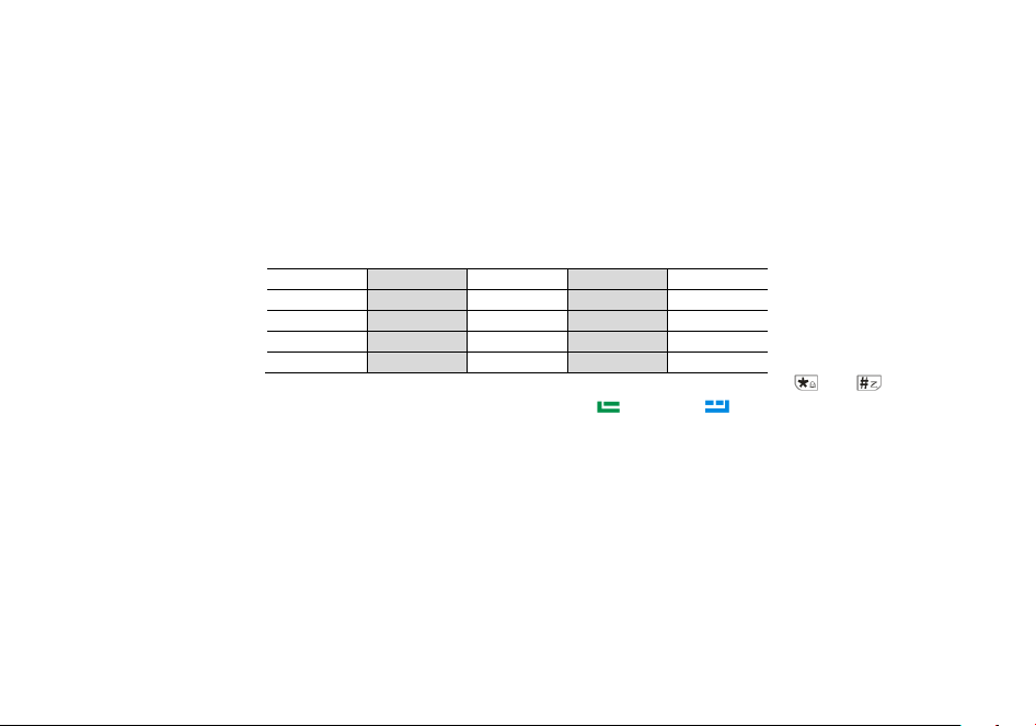
DTMF frequencies and corresponding codes
1209Hz
1336Hz
1477Hz
1633Hz
697Hz
1
2
3
A
770Hz
4
5
6
B
852Hz
7
8
9
C
941Hz
*
0
#
D
The radios has a full implementation of DTMF, including the A, B, C and D codes. The numerical keys, as well as the and keys
correspond to the matching DTMF codes. The A, B, C and D codes are located in the
, , and keys respectively.
To send DTMF codes, press the key(s) corresponding to the message you want to send while holding down the PTT key.
DTMF Enc
Set a DTMF ID as the default call ID for the current channel. Press the PTT key to transmit the selected DTMF ID.
Edit the DTMF ID in Menu or with the PC programing software.
6.3 2Tone Enc
Set a 2Tone as the default call ID for the current channel. Press the PTT key to transmit the selected 2Tone.
Edit the 2Tone in the PC programing software before it can be selected.
6.4 5Tone Enc
Set a 5Tone as the default call ID for the current channel. Press the [PTT] key to transmit the selected 5Tone.
Edit the 5Tone in the PC programing software before it can be selected.

6.5 Dual Watch
In certain situations, the ability to monitor two channels at once can be a valuable asset. This can be achieved in one of two ways. You can
either have one receiver in your radio and flip-flop between two frequencies at a fixed interval (known as Dual Watch), or you can equip a radio
with two receivers (known as Dual Receive or Dual VFO). The former method is cheaper to implement and far more common than the latter.
The radio features Dual Watch functionality (single receiver) with the ability to lock the transmit frequency to one of the two channels it
monitors.
Enabling or disabling Dual Watch mode
(1) Press the
key to enter the main menu.
(2) Enter 2 on the numeric keypad to get to Radio Settings.
(3) Press the
key to confirm, enter 18 on the numeric keypad to get to Dual Watch.
(4) Press the
key to select.
• OFF:
Disable the dual-watch function. Turns off the sub channel, and the radio will display the main channel only. The radio will display the
channel name, frequency and channel sequence on the same screen.
• Double Wait:
Enable the dual-watch function. The radio will display and monitor both channel.
• Signal Wait:
Enable the single-watch function. The radio will display both channel. Transmit and receive on the main channel only, sub
Channel disables reception. Sub channel will Display
icon.
(6) Press the
key to confirm.
(7) Press
to return to the previous menu.
Press and hold to switch Double Wait /
Signal Wait / Off dual watch mode.
6.6 Manual Programming (Channels Memory)
Memory channels are an easy way to store commonly used frequencies so that they can easily be retrieved at a later date.
The radios features 999 memory channels that each can hold: Receive and transmit frequencies, transmit power, group signaling information,
bandwidth, ANI/ PTT-ID settings and a six character alphanumeric identifier or channel name
1
.
Frequency Mode vs. Channel Mode
In standby mode, press [VFO/MR] key to switch between frequency (VFO) mode and channel (MR) mode.
These two modes have different functions and are often confused.
Frequency Mode (VFO): Used for a temporary frequency assignment, such as a test frequency or quick field programming if permitted.
Channel Mode (MR): Used for selecting preprogrammed channels.
Ex 1. Programming a Channel Repeater Offset with CTCSS Tone
EXAMPLE New memory in Channel 28:
RX = 432.55000 MHz
TX = 437.55000 MHz (This is a (+ 5) Offset)
TX CTCSS tone 123.0
(1) Press the
key to switch between menus.
(2) Press [VFO/MR] key to set the radio to VFO mode, and the VFO icon is displayed on the lift.
(3)
[3] [7] 123.0 Selects desired TX encode tone (Ex 123 CTCSS)
(4)
[3] [1][3] [0][5] Enter the OFFSET frequency (Ex. 5.00MHz)
(5)
[3] [1][4] [2] Select the offset direction (Ex. positive offset
)
(6) Enter RX frequency (Ex. 43255000) Enter RX frequency (Ex. 43255000)
(7)
[3] [1][7] [2][8] Enter the same channel (Ex 10)
-->>
channel has been added
(8) Press [VFO/MR] key to return to the MR mode and the channel number will reappear.
Ex 2. Programming a Simplex Channel with CTCSS tone
EXAMPLE New memory in Channel 28:
RX = 432.6500 MHz
TX CTCSS tone 123.0
(1) Press the
key to switch between menus.
(2) Press [VFO/MR] key to set the radio to VFO mode, and the VFO icon is displayed on the lift.
(3)
[3] [7] 123.0 Selects desired TX encode tone (Ex 123 CTCSS)
(4) Enter RX frequency (Ex. 43265000) Enter RX frequency (Ex. 43265000)
(5)
[3] [1][7] [2][8] Enter the same channel (Ex 10)
-->>
channel has been added
(6) Press and hold the
key to return to the MR mode and the channel number will reappear.

6.11 Repeaters Programming
The following instructions assume that you know what transmit and receive frequencies your repeater employs, and that you're authorized to
use it.
(1) Press [VFO/MR] key, the transceiver is set to VFO mode, and the VFO icon will be displayed on the lift.
(2) Use the numeric keypad to enter the repeater's output (your receive) frequency.
(3) Press
[3] [1][3] to get the offset frequency.
(4) Use the numeric keypad to enter the specified frequency offset.
(5) Press
to confirm and save.
(6) Press
[3] [1][4] to get the offset direction.
(7) Use the or keys to select plus (positive) or minus (negative) offset.
(8) Press
to confirm and save.
(9) Optional:
a) Save to memory, see the section called “Manual programming” for details.
b) Set up CTCSS; see the section called “CTCSS” for details.
(10) Press
to exit the menu. If everything went well, you should be able to make a test call through the repeater.
NOTE:
If you're experiencing problems making a connection to the repeater, check your settings and/or go through the procedure again.
Certain Amateur Radio repeaters (especially in Europe) use a 1750Hz tone burst to open up the repeater. To see how this is done with the radios,
see the section called “1750Hz Tone-burst ”.
If you're still unable to make a connection, contact the person in charge of the radio system with your employer or your local amateur radio club,
as the case may be.
6.7 Amateur Radio Setup
In contrast with Commercial radio operators, who often need very specific requirements to be compatible with a very specific radio
implementation, Amateur radio operators tend to need the broadest possible settings in order to be compatible with as many systems as
possible. This basically implies turning all the fancy features that you typically might need for a commercial setup off.
In a typical Amateur radio setup the following settings would be recommended:
Radio setting

• Turn ANI, DTMFST, PTT-ID off and PTT-LT to 0ms (menu items 22 through 24).
• Turn off Squelch Tail Elimination (Tail) features (menu items 26).
• Turn roger beep (ROGER) off (menu item 10).
Program channel
• Set bandwidth to Wide (menu item 4).
• Turn DCS and CTCSS off (menu items 5 through 8).
• Turn Signaling code off and SPK-Mute(menu items 9 and 10).
Chapter 7. Main Menu Functions
The menu function allows you to perform operations such as selecting zones, Setting SCAN, Radio Settings, Program Channels, and viewing
Radio Information.
7.1 Basic use
Use menus with arrow keys
(1) Press the
key to enter the main menu.
(2) Use the or keys to navigate between menu items.
(3) After finding the desired next menu item, press the
key again to select the menu item.
(4) Use the or keys to navigate between the next menu items.
(5) After finding the desired next menu item, press the
key again to select the menu item.
(6) Use the or keys to select the desired parameter.
(7) When you have selected the parameter to be set for a given menu item;
(8) To confirm your selection, press
and it will save your setting and bring you back to the main menu.
(9) To cancel your changes, press
and it will reset that menu item and bring you out of the menu entirely.
(10) To exit out of the menu at any time, press the PTT key.
7.2 Using short-cuts
As you may have noticed if you looked at Appendix C, Menu definitions, every menu item has a numerical value associated with it. These
numbers can be used for direct access of any given menu item.

Using the menu with short-cuts
(1) Press the
key to enter the menu.
(2) Use the numerical keypad to enter the number of the menu item.
(3) To enter the menu item, press
the key.
(4) For entering the desired parameter you have two options:
a) Use the arrow keys as we did in the previous section; or
b) Use the numerical keypad to enter the numerical short-cut code.
(5) And just as in the previous section;
a) To confirm your selection, press and it will save your setting and bring you back to the main menu.
b) To cancel your changes, press and it will reset that menu item and bring you out of the menu entirely.
(6) To exit out of the menu at any time, press the key.
(7) All further examples and procedures in this manual will use the numerical menu short-cuts.
+ 1: Quick access to Zones selection, up to 10 Zones are stored, each zone stores 64 channels;
+ 2: Quickly enter the Scan Settings. You will be able to set the VFO frequency range, Scan mode, Scan Sub-Code, Scan Memory;
+ 3: Quickly enter the Radio settings (general settings of the radio);
+ 4: Quick access to Program Channel (Alias, TX and RX Frequency, TX Power, Bandwidth, Display mode, Channel Memory and Channel
delete);
+ 5: Quickly query the radio information (ANI ID, Firmware version, Hardware version);
+ 6:Quickly enter GNSS position system settings (GNSS switch, time zone setting, position mode setting)
The menu parameters also have a number associated with them, see Appendix B, Menu definitions for details.
7.3 Radio General Settings
7.3.1 Add Zone
Press the [VFO/MR] key to Channel Mode, press the key >> Zone >> Add Zone, name the newly added zone and save it.
The newly added zone will be automatically configured with a channel, allowing parameters such as Channel Name, Receive Freque ncy,
Transmit Frequency, Receive and Transmit CTCSS/DCS to be reset via the Channel Configuration menu.

Add up to 10 zones, add a full 10 zone will automatically hide the “Add Zone” option.
7.3.2 Power On Displya Setting
• Picture: The radio will display a preset picture when powered on. Picture requires .bmp format, size size 160*128 pixels
• Message: Through CPS programming software, General Setup>>General Setup>>Power On Character.
Or through self-station setup, press the
key >> Radio Setting >> Power On Message.
• Voltage:The power voltage is momentarily displayed.
7.3.3 Display Reversal
For ease of use in different work scenarios, the radio's display interface can be oriented STAN and FAIL model.
Press
key >> Radio Settings >> DIR
-STAN: Normal display mode, suitable for desk or handheld scenarios.
-FAIL: the display interface is reversed, applicable to shoulder or waist-mounted scenarios.
7.3.4 MDF-A/ MDF-B Channel Mode A Display
[A][B] MR/Channel Mode Display Format.
Freq: Displays programmed Frequency
Name: Displays the channel name.
CH: Displays the channel number.
7.3.6 Alarm Model
You can select the type of indication when an alarm is activated from the following options.
Press the key >> Intercom Settings >> Alarm Type.
-On Site: the alarm tone is given locally and the control center and group members will not receive the alarm signal.
-Code+Sound: After sending an alarm code to the control center and group members, it will automatically activate the hot microphone and
send a background tone. The receiver will hear the background sound of the alarm. There are no other audible or visual indications.

-Code+Sound(No): After sending an alarm code to the Control Center and group members, no alarm tone will be sent locally. In the alarm state,
there is no sound or visual indication.
-Code+Tone: After sending an alarm code to the control center and group members, a local alarm tone will be emitted. In alarm state, there are
audible and visual indications.
7.3.6 Auto Power Off
Allow to set automatic power off when not used for a period of 30 minutes, 60 minutes, 120 minutes, 240 minutes and 480 minutes of
operation.
Off: Turn off the function.
7.3.7 Power-on Password
Allows the radio to set a power-on password to protect device security and settings.
Press >> Radio Settings >> Password.
Prompts “Input password”.
Enter 1-8 digits (0-9), ******** will be displayed. Press the # key to display your entry.
Press the
key to save and return to the previous menu.
To cancel the power-on password
Press the
key >> Radio Settings >> Password.
Prompts “Input password ********”.
Press the
key to delete until all are deleted.
Press
to save and return to the previous menu.
When the power-on password feature is enabled, the radio will prompt “Input Password” when turning on the radio, and only after entering the
correct password will the radio turn on properly.
The power-on password can be read and modified by CPS software.
7.3.8 Channel Alias

Allows you to view or reset the current channel alias as follows:
1. Press
+[4] to enter Program Channel.
2. Press
to select “CHL NAME”;
3. Press
to enter the channel alias editing interface, and you can perform the following operations:
-Press # key to switch input method, switch between numeric, alphabetic and pinyin input method.
-Press 1 to input symbols such as punctuation or brackets;
-Press 2-9 to insert letters or numbers.
-Press 0 to insert a space.
4. Press
to save the settings and return to the previous menu.
7.4 GPS function
Optional features that require hardware support.
The position system is a typical DTMF calling application. For the method of setting call codes, call names, and local IDs, please refer to
"Signaling Calls".
It is necessary to ensure that the radios that receive and send GPS location information operate on the same frequency or channel, and are set
to the main frequency band.
In GPS mode, you can only view location information and cannot make normal calls. Voice intercom must exit GPS mode in order to proceed.
You can set the system time, GPS on/off, time zone, and GPS mode through the position system menu. Press and hold
key to view, share,
and request location information.
7.4.1 Position On/Off
In standby mode, press key to enter the main menu >> GNSS >> GNSS On/Off.
·Off: Disables the position system.
·On: Activates the position system and the screen displays the icon.
7.4.2 GPS Information

In standby, press key to enter the main menu >> GNSS >> GPS Information.
- My Position
Enter “My Position”, it will display the Longitude (E), Latitude (S),Speed, Altitude, number of Satellites, Date and Time.
Position...: My Position indicator is blinking.
Position successful: My Position indicator is Stable, showing Longitude, Latitude, Speed, Altitude, number of Satellites, Date and Time.
Press the
key to confirm, and press or to cycle through the information of Longitude, Latitude, Altitude, Speed, satellite status, Time
and Date of my position.
Press the
key to return to the previous menu.
- Share Position
Press the key to enter “Share Position”. Options:
·Off: Disable share Position to others.
·On: Enables the function of share Position and allows you to share the position of the camera to others.
- Request Position
Press the key to enter “Request Position”. Options:
-Off: Disable requesting position from others.
-On: Enable the function of requesting position and allow to get the position of others.
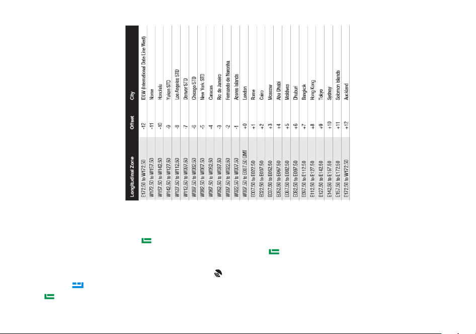
7.4.3 UTC Time Zone
In standby mode, press key to enter main menu >> GNSS >> Time Zone >> Select plus or minus time.
7.4.5 Position system use
Before using the position system, you must turn on the position on/off. To open the position system path:
Method 1: In standby mode, press the
key to enter the main menu >> GNSS >> GPS On/Off.
Method 2: Define the side key function as “GNSS System”. In standby mode, press
key to enter Main Menu >> Radio Settings >> 27-30
Press/LongPress SK1/SK2 >> GNSS System
When the position system is turned on, the screen displays the
icon.
Press and hold
key to enter the GPS member list and automatically jump to the position information from the member (Host).
Press
key to confirm, press or key to cycle through the Longitude, Latitude, Altitude, Speed, satellite status, Time, Date and other

information of the member's local machine.
Note: The member (Host) does not display the position direction pointer.
Press
key to return to the member list.
-Share position (Send position)
In the member (local) display screen, press and hold the PTT key, the transmitter indicator will briefly light up red to share the local position
information to other members.
The receiver receives the shared position and will display the transmitter's member sequence and position information.
-Request a position (Get a position)
Press the key to return to the member list. Press the or key to select a member (but not the Host) in the GPS member list.
Press and hold the PTT key and the transmit indicator briefly lights up red, i.e., a position request is made to that member to obtain the
member's position.
The acquisition of the position is successful and the display is automatically updated with the member's position.
Press the
key to confirm, and press or to cycle through the member's longitude, Latitude, Altitude, Speed, satellite status, Time, Date
and other information and pointers.
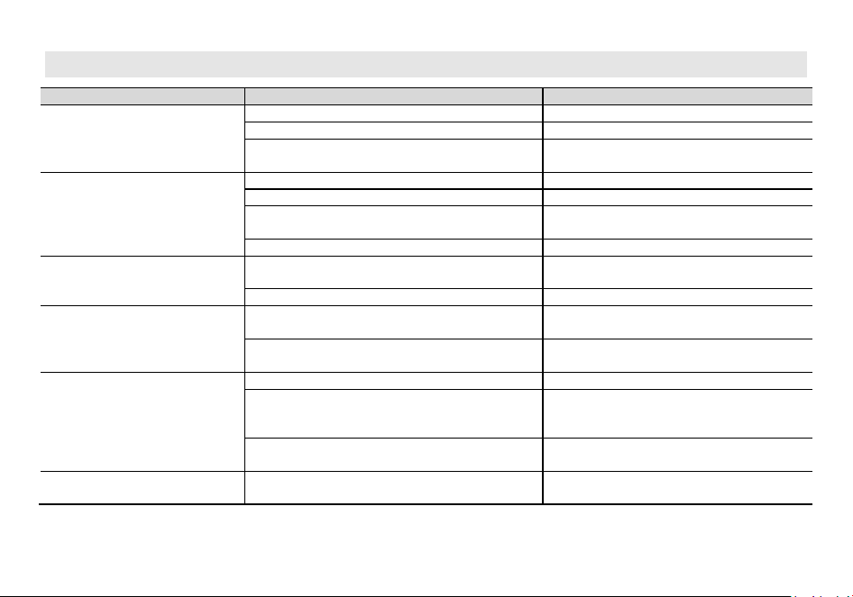
Appendix A. – Trouble shooting guide
Phenomena
Analysis
Solution
You cannot turn on the radio.
The battery may be installed improperly.
Remove and reattach the battery.
The battery power may run out.
Recharge or replace the battery.
The battery may suffer from poor contact caused by dirty
or damaged battery contacts.
Clean the battery contacts or replace the battery.
During receiving, the voice is weak or
intermittent.
The battery voltage maybe low.
Recharge or replace the battery.
The volume level may be low.
Increase the volume.
The antenna maybe loose or maybe installed incorrectly.
Turnoff the radio, and then remove and reattach
the antenna.
The speaker maybe blocked.
Clean the surface of the speaker.
You cannot communicate with other
group members.
The frequency or signaling type maybe inconsistent with
that of other members.
Verify that your TX/RX frequency and signaling type
are correct.
You may be too far away from other members.
Move towards other members.
You hear unknown voices or noise.
You may be interrupted by radios using the same
frequency.
Change the frequency, or adjust the squelch level.
The radio in analog mode maybe set with no signaling.
Request your dealer to set signaling for the current
channel to avoid interference
You are unable to hear anyone
because of too much noise and hiss.
You may be too far away from other members.
Move towards other members.
You may be in an unfavorable position. For example, your
communication may be blocked by high buildings or
blocked in an underground area.
Move to an open and flat area, restart the radio,
and try again.
It may be the result of external disturbance (such as
electromagnetic interference).
Stay away from equipment that may cause
interference.
The radio keeps transmitting.
VOX may be turned on or the headset is not installed in
place
Turn off the VOX function. Check that the
headphones are in place.
NOTE: If the above solutions cannot fix your problems, or you may have some other queries, please contact your dealer
for more technical support.

Appendix B. - Technical Specifications
GENERAL
Channel Capacity
640
Channel Spacing
25.0 KHz/12.5 KHz
Input Voltage
7.4 VDC
Battery Life: 5% TX, 5% RX, 90% Standby
Li-on: 15 hours @ 5 watts
Operating temperature
-10˚C to 60˚C
Antenna Impedance
50Ω
Radio Dimensions
135mm X 63mm X 39mm (not including antenna)
Radio Weight
290 g (with Li-ON battery)
TRANSMITTER
Frequency Range (TX)
144 to 148 MHz, 420 to 450 MHz(America version)
144 to 148 MHz, 430 to 450 MHz(Canadian version)
*144 to 146 MHz, 430 to 440 MHz(EU CE version)
RF Output Power
7 Watts Max
Modulation
16K0F3E/11K0F3E
Spurious Emission
-16 dBm<1GHz, -16 dBm>1GHz
Frequency Stability
±2.5 ppm
Audio Distortion
≤5%
FM Hum & Noise
40 dB
RECEIVER
Frequency Range
108-136, 136-174, 220-260, 350-390, 400 to 520 MHz (Scan Receiver)
*144 to 146 MHz, 430 to 440 MHz(EU CE version)
Sensitivity: 12 dB SINAD
-120 dBm
Adjacent Channel Selectivity
-60 dBm
Intermodulation and Rejection
-70 dBm
Rated Audio Power Output
0.75 Watts @ 16 Ω
Rated Audio Distortion
≤5%
NOTE: All specifications may be modified without prior notice or liability. Thank you.

Appendix C. - Shortcut Menu operations
Main
Menu
Sub Menu
Sequence
Sub Menu Name Settings Description
Zone 1 Zone 1
•Channel 1-Channel 64
•+Add Zone: Add a zone and name the zone. The
newly added zone will default to one channel
430.12500 MHz
Stored zone, at least one zone saved.
Set up to 10 zones and store up to 64 channels
per zone.
No ADD ZONE option when store up to 10 zones.
Scan
1 Freq Ranger
Up Limit-Down Limit
Setting the upper and lower limit values of the
frequency scan range
2 Chan Ranger
•
ALL: Scans all channels in the current zone.
•MEMORY SCAN: Scans for channels that have been
added to the current zone
In channel mode, the channel scan range is
selected. All channels in the current area or
added channels when allowed
3 Scan Mode
•
TO : Time Operation – scanning will resume after a
fixed time has passed
•CO : Carrier Operation - scanning will resume after
the signal disappears
•
SE : Search Operation - scanning will not resume
Scanning Resume Method
4 Scan SubCode
•CTCSS: scan CTCSS (Scanning range 67-254.1)
•DCS: scan DCS ((Scanning range 023N-754I)
Scanning for CTCSS/DCS of known frequencies
5 Scan Memory
•ENCODER: Saved in TX CTCSS/DCS only.
•DECODER: Save only in RX CTCSS/DCS.
•ALL: RX_TX are saved (default is all, i.e., encoding
and decoding are the same)
This function is helpful to decode a CTCSS/DCS
tone if you don’t know the exact code.
Radio
Setting
1 Squelch
•OFF
•Level 1-Level 9
Squelch silences the receiver when there is no
signal.Setting the squelch to 0 will open up the
squelch entirely.
2 Power Save
•OFF
•1:1|1:2|1:4
Selects the ratio of sleep cycles to awake cycles
(1:1, 1:2, 1:4). The higher the number the longer
the battery lasts. The higher number increases
the RX sleep cycle, but you may miss the first few
syllables before the RX opens.

3 VOX Level
•OFF
•Level 1-Level 9
When enabled it is not necessary to push the
[PTT] button on the transceiver. Adjust the gain
level to an appropriate sensitivity to allow
smooth transmission.
4 VOX Delay
1.0……5.0s
When the VOX is enabled, set up the VOX delay to
help to extend the transmission time to avoid
stopping a transmission too early.
5 TOT
•OFF: Transmission is not time-limited, allowing
continuous transmission.
•15;30;45…210
This feature provides a safety switch that limits
transmission time to a programmed value. This
will promote battery conservation by not allowing
you to make excessively long transmissions, and
in the event of a stuck PTT switch it can prevent
interference to other users as well as battery
depletion.
6 TOA
•
OFF: Disable the TOA feature.
•1……10: You can set from 1 to 10 TOA levels. Level 1
means that the transceiver warns you 1 second
before the transmission reaches the TOT; level 2
warns you 2 seconds before the TOT and so on.
With the TOA function enabled, if the TOT
function (Time Out Timer) has been turned on
and your transmission reaches the pre-set
end-transmission time, the transceiver will warn
you and the TX red indicator starts blinking.
7 Voice
•OFF| •Chinese| •English Allows audible voice confirmation of a key press
8 Language
•English| •Chinese
Setting the language type of function menus and
display screens
9 Beep
•OFF: Disable the Beep feature.
•ON: Enable Beep function, every time a button is
pressed, you will hear a Beep tone.
Allows audible confirmation of a key press
10 ROGER
•OFF|•ROGER 1|•ROGER 2|•ROGER 3
Sends an end-of-transmission tone to indicate to
other stations that the transmission has ended.
11 BackLight
•Always On: The backlight is always on.
•5……30
Time-out for the LCD backlight. (seconds)
Note: This function is valid when turn off the
power save.
12 Brightness
1|2|3|4|5
Adjust the brightness of the LCD screen backlight,
1-5 levels of adjustable brightness. 1 level of the
darkest, 5 levels of the brightest
13 Power on Display
•PICTURE: The radio will display an Baofeng picture
when powered on.
Controls the behavior of the display when the
transceiver is turned on.

•MESSAGE: The radio will display the characters set
up in PC software when powered on.
•VOLTAGE: The power voltage is momentarily
displayed.
14 Power on MSG
WELCOME
Allows editing of power-up messages on this unit.
Press MENU to enter message editing, press EXIT
to go forward to delete, and enter text or letters
via the keypad.
15 LCD DIR
•STAN: normal display
•FAIL: Revers display
STAN: normal display . FAIL: Revers display
16 MDF-A
•CH: Displays the channel number
•NAME: Displays the channel name.
•FREQ: Displays programmed Frequency
[A] MR/Channel Mode Display Format.
17 MDF-B
•
CH: Displays the channel number
•NAME: Displays the channel name.
•FREQ: Displays programmed Frequency
[B] MR/Channel Mode Display Format.
18 Dual Watch
•OFF:Disable the dual-watch function.
•Double Wait:Enable the dual-watch function.
•Signal Wait:Enable the single-watch function.
Monitor [A] and [B] at the same time. The display
with the most recent activity ([A] or [B]) becomes
the selected display.
19 AutoLock
•OFF:Manual Lock. Long press the * key to lock the
keypad.
•ON:Auto Lock. Radio will auto lock the keypad when
standby for a while.
Press MENU key, then press the * key to unlock
the keypad.
20 Alarm Mode
•On Site:The radio will emit siren locally, but will not
transmit any emergency signal to the control center.
•Code+Sound:The radio gives visible and audible
indications during emergency state.
•Code+Sound(No):The radio gives no indication
during emergency state, but will unmute its speaker
once it receives a call.
•Code+Tone:The radio transmits the emergency
signals to the control center first, and then gives siren
locally with visible indication.
This option allows you to choose the type of
emergency. The option specifies the type of alert
for the radio during emergency.
21 ID Verification
Contact 1
Contact 80
22 SideTone
•DTMF: DTMF enabled/ disabled.
•2 Tone: 2Tone enabled/ disabled.
•5 Tone: 5Tone enabled/ disabled.
•BDC1200: BDC1200 enabled/ disabled.
OFF: DTMF/2Tone/5Tone/BDC1200 disabled.
ON: DTMF/2Tone/5Tone/BDC1200 enabled.

23 PTT-ID
•OFF: No ID is sent.
•BOT: The selected S-CODE is sent at the beginning.
•EOT: The selected S-CODE is sent at the ending
•BOTH: The selected S-CODE is sent at the beginning
and ending.
When to Send PTT-ID Codes are sent during
either the beginning or ending of a transmission.
24 PTT-DLY 100-3000ms
This function allows you to set the delay in
sending the ANI code once the PTT is pressed
(ANI delay).
You can set it between 100 and 3000ms.
25 ALERT
•1000Hz •1450Hz
•1750Hz •2100Hz
Alert frequency is used to activate some dormant
repeaters, 1000Hz, 1450Hz, 1750Hz, 2100Hz a
total of 4 options are offered.
26 TAIL
•OFF •55Hz:
•120 •180
•240°
This function is used eliminate squelch tail noise
between BaoFeng handhelds that are
communicating directly (no repeater).
Reception of a 55 Hz or 134.4 Hz tone burst
mutes the audio long enough to prevent hearing
any squelch tail noise
27-30
Press/LongPress
SK1
•None:No Function
•SCAN:Scan on/off
•Monitor:Monitor the weak signal.
•Flashlight: Flashlight on/off.
•FM Radio: FM Radio on/off
•SOS: Long press the key to start alarm, short press
again to exit the alarm.
•GNSS System: GPS on/off
•One Touch Search: One Touch Search on/off.
•BT On/Off
•1750Hz:
•Falling Alarm:
•One Touch Call
•Zone:In standby, press the programmed "Zone
Select" key, it will allow you input the zone number
and then press confirm key will switch to the zone.
•Battery Display:Check the current battery capacity
voltage
•Power:Switch the power between super high, high,
middle and low power.
•VOX:Set up the VOX level
This part allows users to assign your desired
features as shortcut to some keys of the radio.
The programmable buttons vary with different
radios. Every key corresponds to two kinds of
operations: long press or short press. They can be
associated to different features or the same
feature.

31 FM Radio
Radio On/Off Turn on or off the FM radio.
Radio Interrupt
On: When FM radio is used, you can still receive
or transmit on the channel.
Off: When FM radio is used, the radio will not
permit a transmission or reception.
32 APO
•OFF: Turn off the function.
•30Min/60Min/120Min/240Min/480Min
Allow to set automatic power off when not used
for a period of 30Min/60Min/120Min/240Min
480Min of operation. Off: Turn off the function.
33 Password Input Password
This option allows users to create a password
required for powering up a radio. Range 0 –
99999999
34 Reset
•VFO: Reset VFO only
•ALL: Reset menu functions and VFO
Resets the radio to factory defaults, with some
exceptions.
Program
Channel
1 CH.NAME Displays the channel name of the current channel
Allow reset the channel name, this function is
only valid in channel mode.
2 RX Frequency Displays the RX frequency of the current channel
Input the RX frequency by keypad, click the Menu
key to save. Press the EXIT key to move forward
and delete bits one by one.
3 TX Frequency Displays the TX frequency of the current channel
Input the TX frequency by keypad, click the Menu
key to save. Press the EXIT key to move forward
and delete bits one by one.
4 Trans Power
•Low: At LOW power transmission
•Meddle:At MID power transmission
•High:At HIGH power transmission
Set up the TX power for current channel.
Selects between HIGH, MID, and LOW transmitter
power when in VFO/Frequency mode. Use the
minimum transmitter power necessary to carry
out the desired communications.
5 Bandwidth
•Narrow: 12.5 kHz bandwidth
•Wide: 25 kHz bandwidth
Choose wide band or narrow band for the analog
channel.
6 RX CTCSS
•OFF
•67-254.1
Mutes the speaker of the transceiver invthe
absence of a specific and continuous sub-audible
signal. If the station you are listening to does not
transmit this specific and continuous signal, you
will not hear anything.

7 RX DCS
•OFF
•023N-754I
Mutes the speaker of the transceiver in the
absence of a specific low-level digital signal. If the
station you are listening to does not transmit this
specific signal, you will not hear anything.
8 TX CTCSS
•OFF
•67-254
Transmits a specific and continuous subaudible
signal to unlock the squelch of a distant receiver
(usually a repeater).
9 TX DCS
•OFF
•023N-754I
Transmits a specific low-level digital signal to
unlock the squelch of a distant receiver (usually a
repeater).
10 Signaling
•DTMF: Set a DTMF ID as the default call ID for the
current channel.
•2Tone: Set a 2Tone as the default call ID for the
current channel.
•5Tone: Set a 5Tone as the default call ID for the
current channel.
•MDC: Set a MDC as the default call ID for the current
channel
Edit the DTMF/ 2Tone/ 5Tone/ BDC1200 in the
PC programing software before it can be selected.
Press the PTT key to transmit the selected DTMF
ID/2Tone/ 5Tone/ BDC1200.
11 SP-Mute
•OFF: You can hear the call once the channel receive
matched carrier.
•QT: You can hear the call when receive matched
CTCSS/DCS signal.
•Optional Signal: You can hear the call when receives
a matched signaling.
•QT+DTMF: You can hear the call when receives a
matched CTCSS/DCS and matched signaling.
When the channel is set up for both CTCSS/DCS
decoding and optional signaling, you can set up
the RX condition in this menu.
12 Scan Add
•
OFF: Disable scanning of the current channel
•ON: Add current channel to scan group
Add the current channel to allow it to be scanned
13 Scan Priority
•OFF: No channel is set as Priority Channel .
•ON: Sets the current channel as the scanning priority
channel.
This option allows users to select a channel in the
scan list as Priority Channel. If only Priority
Channel is set, 50% of a radio's scans are on
Priority Channel during scanning.
14 TX Admit
•Always: The user can transmit all the time.
•Channel Free: The radio allows transmission only
when the current channel is free.
•CTDS Correct: The radio can transmit when the
current channel is free or CTCSS/CDCSS is matched.
This option defines the response from the
transmitter upon PTT press on the current
channel, in order to prevent the user transmitting
on channels that are already in use.

15 Skip Frequency
•OFF: Disable the Skip Frequency feature
•ON: Enable Skip Frequency function
16 Scramber
•OFF: Disable the Scramber feature
•ON: Enable Scramber function
This option allows you to decide whether to
enable the Scrambler feature. This technology
can invert the frequency spectrum at the
transmitting party to make the signal
unintelligible to unwanted at a receiving party, so
as to achieve communication privacy not
equipped with an appropriately set descrambling
device.
17 CH_Memory
CH01-CH64
This menu is used to either create new or modify
existing channels, so that they can be accessed
from MR/Channel Mode.
18 CH_Delete
CH01-CH64
This menu is used to delete the programmed
information from the specified channel. so that it
can either be programmed again or be left empty.
Radio Info
1 Versions
•
Firmware Versions
•Hardware Versions
Show the Radio ID, Radio name, serial number,
model name, frequency range, firmware version,
radio data version, latest program date, picture
version, language version etc.
2 My Radio
•Radio ID: View radio ID and allow reset of DTMF ID,
5Tone ID
•Radio Name: View radio aliases and allow resetting
of aliases
GNSS
1 GNSS On/Off
•OFF: Disable the GNSS feature
•ON: Enable GHSS function
Turn on GPS
2 GPS Info
•My Position: View My Position.
•Share Position: Share Position switch to confirm that
sharing position is allowed.
•Request Position: Request position switch to check
whether it is allowed to accept a request for locate
from another person.
3 Time Zones UTC-12:00 - UTC+13:00
Users can select a desired time zone from the
drop-down list. The radio adjusts its time
according to the selected time zone.
NOAA
Weather
1 Weather On/Off
OFF: Disable the NOAA weather feature.
•WX 1 162.55000 •WX 2 162.55000
•WX 3 162.55000 •WX 4 162.55000
•WX 5 162.55000 •WX 6 162.55000
•WX 7 162.55000 •WX 8 162.55000
•WX 9 162.55000 •WX10 162.55000
Enter NOAA weather. Press and hold the 0 key for
quick access to the NOAA Weather feature
2 Weather Alert
•OFF: Disable the weather alert feature.
•ON: Enable the Weather Alert feature on the current
NOAA Weather Channel.
The weather alert feature is available in North
America only. Consult your local radio authority
for specific frequencies
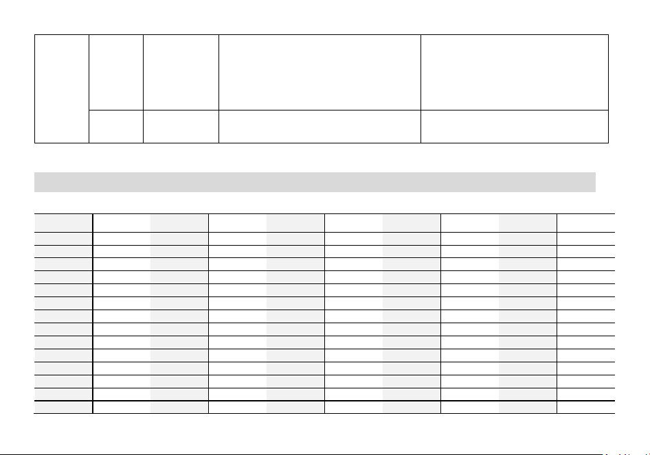
Appendix D. - DCS Table
DCS CODE LIST
Number
Code
Number
Code
Number
Code
Number
Code
Number
Code
1
D023N
2
D025N
3
D026N
4
D031N
5
D032N
6
D036N
7
D043N
8
D047N
9
D051N
10
D053N
11
D054N
12
D065N
13
D071N
14
D072N
15
D073N
16
D074N
17
D114N
18
D115N
19
D116N
20
D122N
21
D125N
22
D131N
23
D132N
24
D134N
25
D143N
26
D145N
27
D152N
28
D155N
29
D156N
30
D162N
31
D165N
32
D172N
33
D174N
34
D205N
35
D212N
36
D223N
37
D225N
38
D226N
39
D243N
40
D244N
41
D245N
42
D246N
43
D251N
44
D252N
45
D255N
46
D261N
47
D263N
48
D265N
49
D266N
50
D271N
51
D274N
52
D306N
53
D311N
54
D315N
55
D325N
56
D331N
57
D332N
58
D343N
59
D346N
60
D351N
61
D356N
62
D364N
63
D365N
64
D371N
65
D411N
66
D412N
67
D413N
68
D423N
69
D431N
70
D432N

71
D445N
72
D446N
73
D452N
74
D454N
75
D455N
76
D462N
77
D464N
78
D465N
79
D466N
80
D503N
81
D506N
82
D516N
83
D523N
84
D526N
85
D532N
86
D546N
87
D565N
88
D606N
89
D612N
90
D624N
91
D627N
92
D631N
93
D632N
94
D645N
95
D654N
96
D662N
97
D664N
98
D703N
99
D712N
100
D723N
101
D731N
102
D732N
103
D734N
104
D743N
105
D754N
106
D023I
107
D025I
108
D026I
109
D031I
110
D032I
111
D036I
112
D043I
113
D047I
114
D051I
115
D053I
116
D054I
117
D065I
118
D071I
119
D072I
120
D073I
121
D074I
122
D114I
123
D115I
124
D116I
125
D122I
126
D125I
127
D131I
128
D132I
129
D134I
130
D143I
131
D145I
132
D152I
133
D155I
134
D156I
135
D162I
136
D165I
137
D172I
138
D174I
139
D205I
140
D212I
141
D223I
142
D225I
143
D226I
144
D243I
145
D244I
146
D245I
147
D246I
148
D251I
149
D252I
150
D255I
151
D261I
152
D263I
153
D265I
154
D266I
155
D271I
156
D274I
157
D306I
158
D311I
159
D315I
160
D325I
161
D331I
162
D332I
163
D343I
164
D346I
165
D351I
166
D356I
167
D364I
168
D365I
169
D371I
170
D411I
171
D412I
172
D413I
173
D423I
174
D431I
175
D432I
176
D445I
177
D446I
178
D452I
179
D454I
180
D455I
181
D462I
182
D464I
183
D465I
184
D466I
185
D503I
186
D506I
187
D516I
188
D523I
189
D526I
190
D532I
191
D546I
192
D565I
193
D606I
194
D612I
195
D624I
196
D627I
197
D631I
198
D632I
199
D645I
200
D654I
201
D662I
202
D664I
203
D703I
204
D712I
205
D723I
206
D731I
207
D732I
208
D734I
209
D743I
210
D754I
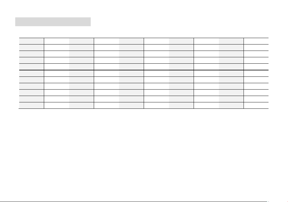
Appendix E. - CTCSS Table
CTCSS CHART (Hz)
Number
Frequency
Number
Frequency
Number
Frequency
Number
Frequency
Number
Frequency
1
67.0
2
69.3
3
71.9
4
74.4
5
77.0
6
79.7
7
82.5
8
85.4
9
88.5
10
91.5
11
94.8
12
97.4
13
100
14
103.5
15
107.2
16
110.9
17
114.8
18
118.8
19
123.0
20
127.3
21
131.8
22
136.5
23
141.3
24
146.2
25
151.4
26
156.7
27
159.8
28
162.2
29
165.5
30
167.9
31
171.3
32
173.8
33
177.3
34
179.9
35
183.5
36
186.2
37
189.9
38
192.8
39
196.6
40
199.5
41
203.5
42
206.5
43
210.7
44
218.1
45
225.7
46
229.1
47
233.6
48
241.8
49
250.3
50
254.1

Disclaimer
The accuracy and completeness of the contents are sought in the process of compilation, but we do not bear any
responsibility for the possible errors or omissions. With the continuous development of technology, we reserve the right to
change the design and specification of the product without notice. No copy, modification, translation and dissemination of
this handbook may be made in any form without the prior written authorization of our department.
PO FUNG ELECTRONIC (HK) INTERNATONAL GROUP COMPANY LIMITED
ADD: Room 1508, 15/F, Office Tower II, Grand Plaza, 625 Nathan Road, Kowloon, Hong Kong
Http://www.baofengradio.com www.pofungshop.com
Print version: 5RH PRO(501) V1.0