1
Majestic • TRILLIANT25IN/IL, TRILLIANT30IN/IL, TRILLIANT35IN/IL Installation Manual • 2571-980 Rev. G • 6/24
Installation Manual
Installation and Appliance Setup
NOTICE: DO NOT discard this manual!
This appliance may be installed as an OEM
installation in manufactured home (USA
only) or mobile home and must be installed
in accordance with the manufacturer’s
instructions and the Manufactured Home
Construction and Safety Standard, Title 24
CFR, Part 3280 in the United States, or the
Standard for Installation in Mobile Homes,
CAN/CSA Z240 MH Series, in Canada.
This appliance is only for use with the type(s)
of gas indicated on the rating plate. This
appliance is not convertible for use with other
gases, unless a certied kit is used.
• DO NOT store or use gasoline or other am-
mable vapors and liquids in the vicinity of this
or any other appliance.
• What to do if you smell gas
- DO NOT try to light any appliance.
- DO NOT touch any electrical switch. DO
NOT use any phone in your building.
- Leave the building immediately.
- Immediately call your gas supplier from
a neighbor’s phone. Follow the gas sup-
plier’s instructions.
- If you cannot reach your gas supplier, call
the re department.
• Installation and service must be performed
by a qualied installer, service agency, or the
gas supplier.
WARNING:
FIRE OR EXPLOSION HAZARD
Failure to follow safety warnings exactly
could result in serious injury, death, or
property damage.
DANGER
HOT GLASS WILL
CAUSE BURNS.
DO NOT TOUCH GLASS
UNTIL COOLED.
NEVER ALLOW CHILDREN
TO TOUCH GLASS.
A barrier designed to reduce the risk of
burns from the hot viewing glass is provided
with this appliance and must be installed for
the protection of children and other at-risk
individuals.
CAUTION! Risk of Fire! DO NOT store instruction manuals inside replace cavity. High temperatures
could cause a re.
INSTALLER: Leave this manual with the appliance, not inside the appliance.
CONSUMER: Retain this manual for future reference. Do not store inside the appliance
Pour demander un exemplaire en français de ce manuel
d’installation, visitez www.majesticproducts.com.
Models:
TRILLIANT25IN
TRILLIANT30IN
TRILLIANT35IN
TRILLIANT25IL
TRILLIANT30IL
TRILLIANT35IL

2
Majestic • TRILLIANT25IN/IL, TRILLIANT30IN/IL, TRILLIANT35IN/IL Installation Manual • 2571-980 Rev. G • 6/24
Table of Contents
Installation Standard Work Checklist .................... 3
1 Product Specic and Important Safety Information
A. Appliance Certication ............................4
B. Glass Specications .............................. 4
C. BTU Specications ............................... 4
D. High Altitude Installations .......................... 4
E. Non-Combustible Materials Specication. . . . . . . . . . . . . . 4
F. Combustible Materials Specication .................4
G. Electrical Codes .................................4
H. California ......................................4
2 Getting Started
A. Design and Installation Considerations ...............5
B. Good Faith Wall Surface .......................... 7
C. Tools and Supplies Needed ........................7
D. Inspect Appliance and Components ..................7
3 Appliance / Fireplace Requirements and
Clearances
A. Appliance/Decorative Barrier Front Dimension Diagrams . 8
B. Minimum Fireplace Opening ......................14
C. Zero Clearance Wall Extension ....................16
D. Mantel, Wall Projections, & Hearth Extensions ........ 18
E. Hearth Extension / Vinyl Flooring ................... 19
4 Installation Preparation
A. Cleaning ......................................21
B. Flue Damper. . . . . . . . . . . . . . . . . . . . . . . . . . . . . . . . . . . 21
C. Gas Line ...................................... 21
D. Fireplace Conversion Notice ......................21
E. Electrical Outlet Box ............................. 21
5 Installing Vent Pipe and Appliance
A. Vent Limits ....................................22
B. Using Vertical Restrictor .......................... 23
C. Venting Components ............................24
D. Connecting to SLP ..............................25
E. Connecting Vent Pipe ............................26
F. Placing, Securing and Leveling the Appliance .........27
G. Installing Termination Cap ........................28
6 Electrical Information
A. General Information .............................29
B. Wiring Requirements ............................30
C. Installation / Service for Fan ...................... 31
D. Installation / Service for Halogens ..................32
7 Gas Information
A. Fuel Conversion ................................33
B. Gas Pressure ..................................34
C. Gas Connection ................................34
D. High Altitude Installations ......................... 35
E. Air Shutter Setting ..............................35
F. Service / Replace Appliance Gas Valve ..............35
8 Finishing
A. Mantel, Wall Projections & Hearth Extensions .........36
B. Hearth Extension ...............................37
9 Appliance Setup
A. Fixed Glass Assembly ...........................39
B. Remove the Shipping Materials .................... 40
C. Clean the Appliance ............................. 40
D. Accessories ...................................40
E. Refractory ....................................41
F. Ember Rocks Placement ......................... 43
G. Mystic Embers Placement ........................43
H. Ember Placement ...............................43
I. Install the Log Assembly. . . . . . . . . . . . . . . . . . . . . . . . . . 44
J. Install Decorative Barrier Front and Surround ......... 52
K. Appliance Break-In .............................. 53
L. Heat Management .............................. 53
10 Reference Materials
A. Vent Components ...............................54
B. Accessories ...................................55
= Contains updated information.
Safety Alert Key:
• DANGER! Indicates a hazardous situation which, if not avoided will result in death or serious injury.
• WARNING! Indicates a hazardous situation which, if not avoided could result in death or serious injury.
• CAUTION! Indicates a hazardous situation which, if not avoided, could result in minor or moderate injury.
• NOTICE: Used to address practices not related to personal injury.
Note: The term “recommend” or “recommended” does not indicate a requirement. It is a best practice suggested by Hearth
& Home Technologies
®
.
3
Majestic • TRILLIANT25IN/IL, TRILLIANT30IN/IL, TRILLIANT35IN/IL Installation Manual • 2571-980 Rev. G • 6/24
Installation Standard Work Checklist
Customer:
Lot/Address:
Model (circle one): TRILLIANT25IN, TRILLIANT25IL
TRILLIANT30IN, TRILLIANT30IL, TRILLIANT35IN, TRILLIANT35IL
Date Installed:
Location of Fireplace:
Installer:
Dealer/Distributor Phone #
Serial #:
Comments: Further description of the issues, who is responsible (Installer/ Builder/ Other Trades, etc) and corrective
action needed _____________________________________________________________________________________
_________________________________________________________________________________________________
_________________________________________________________________________________________________
Comments Communicated to party responsible ____________________ by ______________________on ___________
(Builder / Gen. Contractor/) (Installer) (Date)
Appliance Install YES IF NO, WHY?
Veried replace is clean and remove/block open damper/modify
damper for vent pipe clearance (Section 4). ___________________________
Veried clearances to combustibles (Sections 3, 5, 8). ___________________________
Locate multi-purpose tool (Section 2). ___________________________
Appliance is leveled and secured (Section 5.F). ___________________________
Venting/Chimney Section 5
Exhaust and inlet ex vent pipe are properly formed and routed through
existing replace damper. ___________________________
Exhaust and inlet ex vent pipe are properly installed to the correct collars,
sealed and secured to top slide plate and to the termination cap. ___________________________
Vertical restrictors are properly set (if applicable). ___________________________
Exterior roof ashing installed and sealed. ___________________________
Termination cap installed, secured and sealed to top slide plate. ___________________________
Electrical Section 6
Unswitched power (110-120 VAC) provided to the appliance. ___________________________
Switch wires properly installed. ___________________________
Gas Section 7
Proper appliance for fuel type. ___________________________
Was a conversion performed? ___________________________
Leak check performed and inlet pressure veried. ___________________________
Veried proper air shutter setting for installation type. ___________________________
Finishing Section 8
Combustible materials not installed in non-combustible areas. ___________________________
Veried all clearances meet installation manual requirements. ___________________________
Mantels and wall projections comply with installation manual requirements. ___________________________
Appliance Setup Section 9
All packaging and protective materials removed (inside & outside of appliance). ___________________________
Refractories, logs, media and embers installed correctly. ___________________________
Glass assembly and glass seal plate installed and secured. ___________________________
Accessories installed properly. ___________________________
Surround and decorative front properly installed. See instructions shipped
with appliance front. ___________________________
Manual bag and all of its contents are removed from inside/under
the appliance and given to party responsible for use and operation. ___________________________
Fireplace warning plate is attached to the existing woodburning replace. ___________________________
Remote control is programmed, functions veried using remote control ___________________________
instructions.
Started appliance and veried no gas leaks exist. ___________________________
2571-982C 6/24
= Contains updated information.
Hearth & Home Technologies recommends the following:
• Photographing the installation and copying this checklist for your le.
• That this checklist remain visible at all times on the appliance until the installation is complete.
This standard work checklist is to be used by the installer in conjunction with, not instead of, the instructions contained in this
installation manual.
WARNING! Risk of Fire or Explosion! Failure to install appliance according to these instructions could
lead to a re or explosion.
ATTENTION INSTALLER:
Follow this Standard Work Checklist

4
Majestic • TRILLIANT25IN/IL, TRILLIANT30IN/IL, TRILLIANT35IN/IL Installation Manual • 2571-980 Rev. G • 6/24
A. Appliance Certication
E. Non-Combustible Materials Specication
Material which will not ignite and burn. Such materials are
those consisting entirely of steel, iron, brick, tile, concrete,
slate, glass or plasters, or any combination thereof.
Materials that are reported as passing ASTM E 136,
Standard Test Method for Behavior of Materials in
a Vertical Tube Furnace at 750 ºC shall be considered
non-combustible materials.
F. Combustible Materials Specication
Materials made of or surfaced with wood, compressed pa-
per, plant bers, plastics, or other material that can ignite
and burn, whether ame proofed or not, or plastered or
unplastered shall be considered combustible materials.
G. Electrical Codes
NOTICE: This appliance must be electrically wired
and grounded in accordance with local codes or, in the
absence of local codes, with National Electric Code
ANSI/NFPA 70-latest edition or the Canadian Electric
Code CSA C22.1.
• A 110-120 VAC circuit for this product must be pro-
tected with ground-fault circuit-interrupter protection,
in compliance with the applicable electrical codes,
when it is installed in locations such as in bathrooms
or near sinks.
1 1
Product Specic and Important Safety Information
This product is listed to ANSI standards for “Vented Gas
Fireplace Heaters” and applicable sections of “Gas Burn-
ing Heating Appliances for Manufactured Homes and
Recreational Vehicles”, and “Gas Fired Appliances for
Use at High Altitudes”.
NOT INTENDED FOR USE AS A PRIMARY HEAT SOURCE.
This appliance is tested and approved as either supplemen-
tal room heat or as a decorative appliance. It should not be
factored as primary heat in residential heating calculations.
NOTICE: This installation must conform with local codes.
In the absence of local codes you must comply with the
National Fuel Gas Code, ANSI Z223.1-latest edition in
the U.S.A. and the CAN/CGA B149 Installation Codes in
Canada.
B. Glass Specications
This appliance is equipped with ceramic glass. Replace
glass only with ceramic glass. Please contact your dealer
for replacement glass.
C. BTU Specications
D. High Altitude Installations
NOTICE: If the heating value of the gas has been reduced,
these rules do not apply. Check with your local gas utility
or authorities having jurisdiction.
When installing above 2000 feet elevation:
• In the USA: Reduce input rate 4% for each 1000 feet
above 2000 feet.
• In CANADA: Input ratings are certied without a eduction
of input rate for elevations up to 4500 feet (1370 m)
above sea level. Please consult provincial and/or
local authorities having jurisdiction for installations at
elevations above 4500 feet (1370 m).
Check with your local gas utility to determine proper
orice size.
H. California
WARNING: This product and the fuels used to
operate this product (liquid propane or natural
gas), and the products of combustion of such fuels, can
expose you to chemicals including benzene, which is
known to the State of California to cause cancer and
reproductive harm. For more information go to: www.
P65Warnings.ca.gov.
MODELS: TRILLIANT25IN, TRILLIANT25IL
TRILLIANT30IN, TRILLIANT30IL
TRILLIANT35IN, TRILLIANT35IL
LABORATORY: Underwriters Laboratories, Inc. (UL)
TYPE: Direct Vent Heater
STANDARD: ANSI Z21.88-2019 CSA 2.33-2019
Models
(U.S. or Canada)
Maximum
Input
BTU/h
Minimum
Input
BTU/h
Orice
Size
(DMS)
TRILLIANT25IN
(NG)
(0-2000 FT) 27,000 18,900 40
TRILLIANT25IL
(Propane)
(0-2000 FT) 25,000 17,500 53
TRILLIANT30IN
(NG)
(0-2000 FT) 32,700 22,890 35
TRILLIANT30IL
(Propane)
(0-2000 FT) 32,000 22,400 51
TRILLIANT35IN
(NG)
(0-2000 FT) 35,000 24,500 33
TRILLIANT35IL
(Propane)
(0-2000 FT) 35,000 24,500 50
5
Majestic • TRILLIANT25IN/IL, TRILLIANT30IN/IL, TRILLIANT35IN/IL Installation Manual • 2571-980 Rev. G • 6/24
2 2
Getting Started
Improper installation, adjustment, alteration, service or
maintenance can cause injury or property damage. For
assistance or additional information, consult a qualied
service technician, service agency or your dealer.
A. Design and Installation Considerations
WARNING! Risk of Fire or Explosion! Read all instruc-
tions before starting the installation
Gas inserts are designed for installations into solid fuel
masonry or UL127 listed factory built replaces. No ad-
ditional outside air source is required.
Installation MUST comply with local, regional, state and na-
tional codes and regulations. Consult insurance carrier, local
building inspector, re ofcials or authorities having jurisdic-
tion over restrictions, installation inspection and permits.
Prior to installing the gas insert:
• Ensure chimney is constructed of non-combustible
materials.
• Ensure chimney is clean and in good working order.
• Ensure that all chimney cleanouts t properly to prevent
air leakage into chimney.
• Ensure combustible mantel and surround clearances
comply with insert requirements.
• Ensure all joints are properly engaged and the chimney
is properly secured.
• Determine minimum replace size. See Section 3.A and
3.B.
• Determine gas supply piping requirements.
• Determine electrical wiring requirements.
• Determine nishing details.
• Determine whether optional accessories—devices such
as a wall switch or remote control—are desired.
Installation and service of this appliance should be performed by
qualied personnel. Hearth & Home Technologies recommends
HHT Factory Trained or NFI certied professionals.
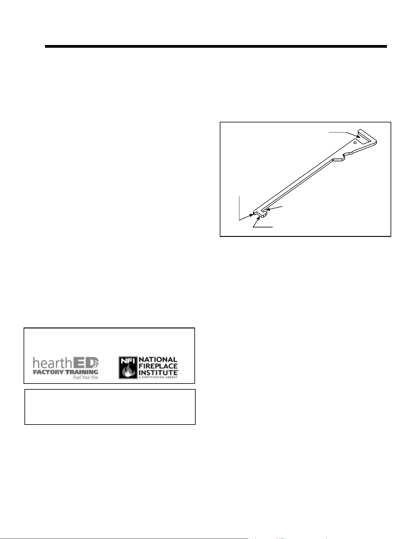
Figure 2.1 Multi-Purpose Tool
GAS SHUT-OFF
DISENGAGE
SLIDE PLATE
ENGAGE
SLIDE PLATE
GLASS CLIPS
Multi-Purpose Tool
• See Figure 2.1 for multi-purpose tool functions and
features.
• See Figure 2.2 for multi-purpose tool shipping location.
• See Figure 2.3 for multi-purpose tool storage location
options.
6
Majestic • TRILLIANT25IN/IL, TRILLIANT30IN/IL, TRILLIANT35IN/IL Installation Manual • 2571-980 Rev. G • 6/24
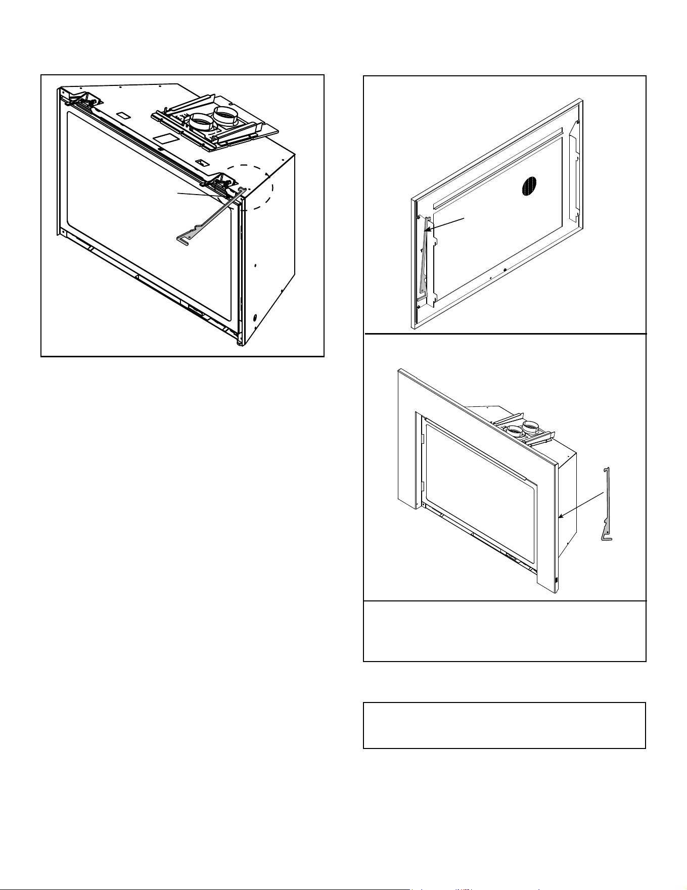
Figure 2.3 Multi-Purpose Tool Storage Options
OPTION B
OPTION A
MULTI-PURPOSE TOOL
MULTI-PURPOSE
TOOL SHIPPED ZIP-
TIED IN THIS AREA OF
THE APPLIANCE
Figure 2.2 Multi-Purpose Tool shipping Location
OPTION C
Multi-purpose tool can be stored in appliance manual
bag.
Multi-purpose tool can be
stored behind the surround.
Multi-purpose tool can be
stored behind the appliance
front.
Multi-Purpose Tool - Shipping Location
Multi-Purpose Tool - Storage Options
NOTE: This is not an option for
all Inside Fit (INFIT) fronts.
• Remove multi-purpose tool by cutting and discarding
zip-tie.
• See Figure 2.3 for multi-purpose tool storage.
• See Figure 2.1 for multi-purpose tool features / functions.
DO NOT store appliance manual bag in or around
the appliance.
7
Majestic • TRILLIANT25IN/IL, TRILLIANT30IN/IL, TRILLIANT35IN/IL Installation Manual • 2571-980 Rev. G • 6/24
D. Inspect Appliance and Components
• Carefully remove the appliance and components from
the packaging.
• The vent system components, decorative barrier fronts
and surrounds are shipped in separate packages.
• If packaged separately, the log set and appliance grate
must be installed.
• Report to your dealer any parts damaged in shipment,
particularly the condition of the glass.
• Read all of the instructions before starting the instal-
lation. Follow these instructions carefully during the
installation to ensure maximum safety and benet.
WARNING! Risk of Fire or Explosion! Damaged parts
could impair safe operation. DO NOT install damaged, in-
complete or substitute components. Keep appliance dry.
Hearth & Home Technologies disclaims any responsibility for,
and the warranty will be voided by, the following actions:
• Installation and use of any damaged appliance or vent
system component.
• Modication of the appliance or vent system.
• Installation other than as instructed by Hearth & Home
Technologies.
• Improper positioning of the gas logs or the glass door.
• Installation and/or use of any component part not approved
by Hearth & Home Technologies.
Any such action may cause a re hazard.
WARNING! Risk of Fire, Explosion or Electric Shock!
DO NOT use this appliance if any part has been under
water. Call a qualied service technician to inspect the
appliance and to replace any part of the control system
and/or gas control which has been under water.
C. Tools and Supplies Needed
Before beginning the installation be sure that the following
tools and building supplies are available.
Tape measure Pliers
Hammer Phillips screwdriver
Voltmeter Electric drill and bits (1/4 in.)
Gloves Safety glasses
Level Reciprocating saw
Manometer Flat blade screwdriver
Stove cement / Aluminum foil tape
3/16 in. Allen wrench (Rear Leveling Legs)
Elongated pressure taps (Recommended)
Noncorrosive leak check solution
Caulking material (300 ºF minimum continuous exposure
rating)
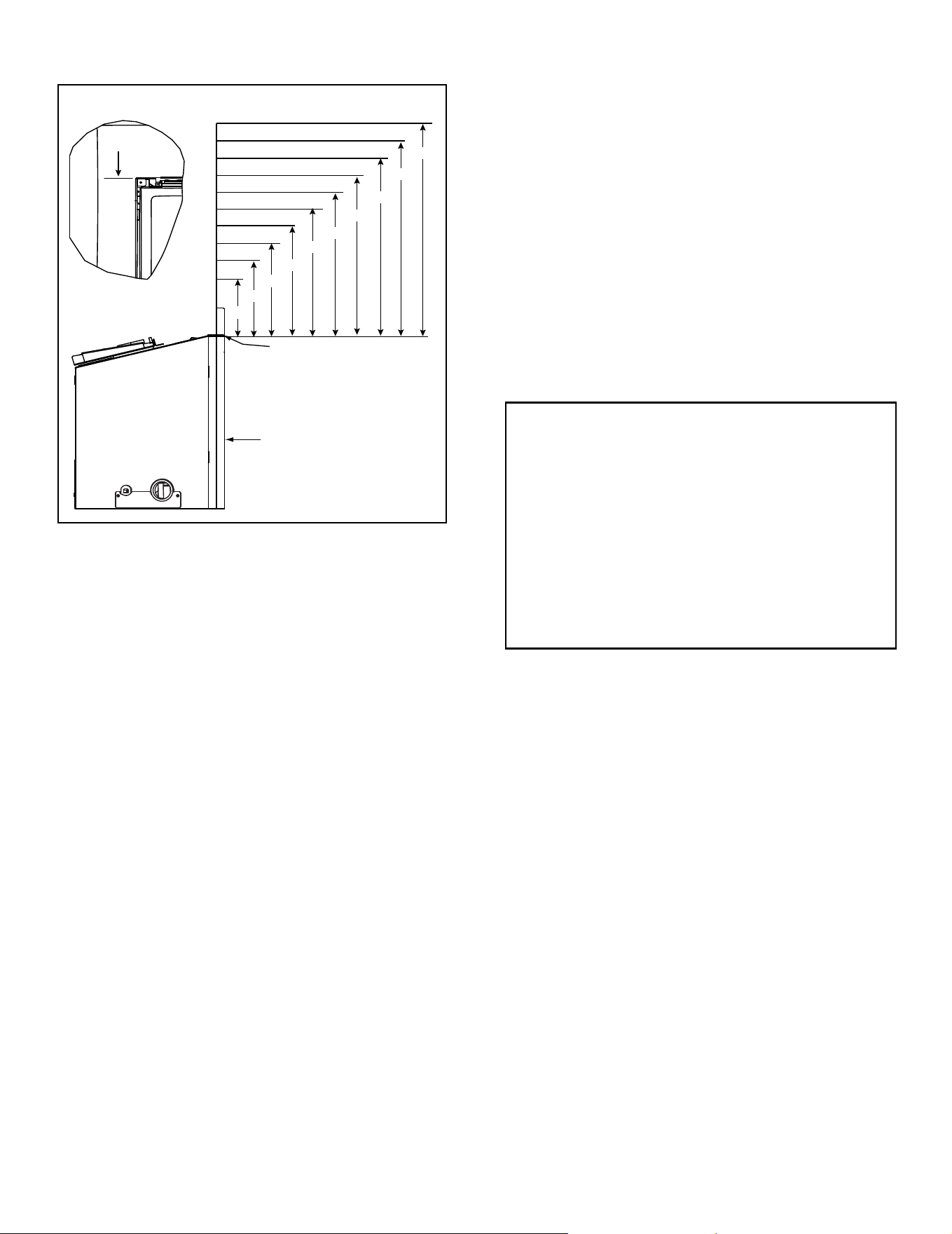
Figure 2.4 Good Faith Wall Surface Temperatures Above Appliance
B. Good Faith Wall Surface
NOTICE: Temperatures listed above are taken with a
temperature measuring probe as prescribed by the test
standard used for appliance certication. Temperatures
on walls or mantels taken with an infrared thermometer
may yield increased temperatures of up to 30 ºF or more
depending on the thermometer settings and material
characteristics being measured. Use appropriate nishing
materials that are able to withstand these conditions. For
additional nishing guidelines, see Section 8.
MEASUREMENTS FROM TOP
OF THE SURROUND OPENING
CEILING
APPLIANCE SURROUND
SURROUND
OPENING
18 IN.
22 IN.
16 IN.
12 IN.
24 IN.
28 IN.
34 IN.
40 IN.
46 IN.
52 IN.
151 ºF
138 ºF
135 ºF
127 º F
125 º F
120 ºF
115 ºF
110 ºF
108 º F
106 º F
If installing a television (TV) above the appliance, see
Section 3 of the appliance Owner’s Manual.
8
Majestic • TRILLIANT25IN/IL, TRILLIANT30IN/IL, TRILLIANT35IN/IL Installation Manual • 2571-980 Rev. G • 6/24
3 3
Appliance / Fireplace Requirements and Clearances
A. Appliance/Decorative Barrier Front Dimension Diagrams
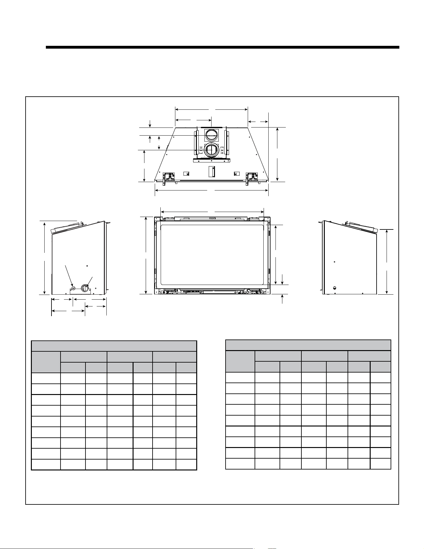
Dimensions are actual appliance dimensions. Use for reference only. For addditional clearances refer to Sections 3.D and 3.E.
Figure 3.1 Appliance Dimensions
*Note: Location G is the appliance depth measurement, for installation depth reference Location E on
Figure 3.9.
MODEL DIMENSIONS
Location
25 in. 30 in. 35 in.
IN MM IN MM IN MM
A 14-5/8 372 19-5/8 499 24-5/8 626
B 26-1/8 664 31-1/8 791 36-1/8 918
C 22-1/2 572 27-1/2 699 32-1/2 826
D 12-7/16 316 15-15/16 405 19-3/8 492
E 17-1/16 433 20-3/4 527 24 610
F 16-5/8 422 20-1/8 511 23-5/8 600
G* 14-1/2 368 14-1/2 369 14-1/2 368
H 7-5/16 186 9-13/16 249 12-5/16 313
I 15 381 18-15/16 481 21-7/16 545
F
K
J
GAS LINE
ACCESS
C
D
E
R
I
A
H
B
G
O
N
P
Q
ELECTRICAL
ACCESS
L
M
MODEL DIMENSIONS
Location
25 in. 30 in. 35 in.
IN MM IN MM IN MM
J 5-11/16 144 5-11/16 144 5-11/16 144
K 5-7/8 149 5-7/8 149 5-7/8 149
L 9 229 9 229 9 229
M 8-3/4 222 8-3/4 222 8-3/4 222
N 2-1/8 54 2-1/8 54 2-1/8 54
O 4-1/16 103 4-1/16 103 4-1/16 103
P 5-3/4 146 5-3/4 146 5-3/4 146
Q 8-3/4 222 8-3/4 222 8-3/4 222
R 2-7/16 62 2-7/16 62 2-7/16 62
TOP VIEW
LEFT SIDE
RIGHT SIDE
FRONT VIEW
9
Majestic • TRILLIANT25IN/IL, TRILLIANT30IN/IL, TRILLIANT35IN/IL Installation Manual • 2571-980 Rev. G • 6/24
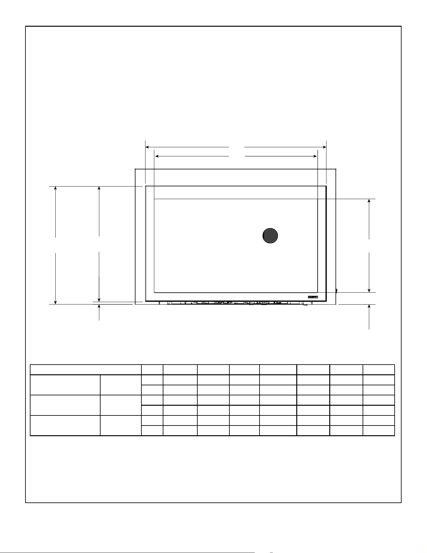
Figure 3.2 Decorative Barrier Front Dimensions - Clean Screen
F
D
A
B
C
G
E
*
DECORATIVE BARRIER FRONTS - CLEAN SCREEN
A B C D E F G
TRILLIANT25I CSFI25
in. 27-3/8 15-1/8 3-1/2 31 20 19-1/2 1/2
mm 695 384 89 787 508 495 13
TRILLIANT30I CSFI30
in. 32-3/8 18-5/8 3-1/8 36 23-1/2 23 1/2
mm 822 473 79 914 597 584 13
TRILLIANT35I CSFI35
in. 37-3/8 22-1/8 3-1/8 41 27 26-1/2 1/2
mm 949 562 79 1041 686 673 13
* NOTICE: 1/2 inch gap must be maintained
or components will overheat.
10
Majestic • TRILLIANT25IN/IL, TRILLIANT30IN/IL, TRILLIANT35IN/IL Installation Manual • 2571-980 Rev. G • 6/24
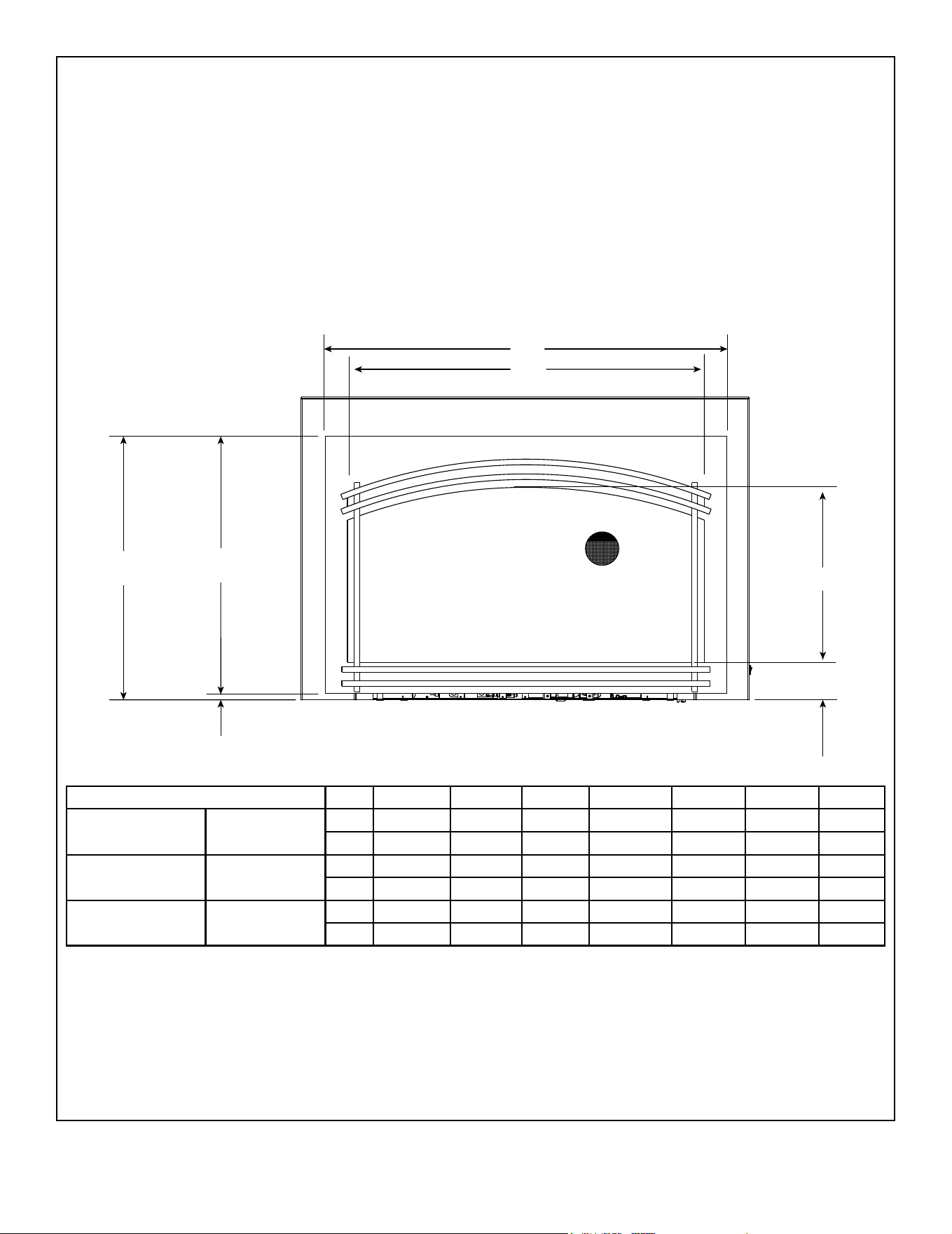
Figure 3.3 Decorative Barrier Front Dimensions - Forge Arch
DECORATIVE BARRIER FRONT - FORGE ARCH
A B C D E F G
TRILLIANT25I FA-TRI25
in. 27 14-3/4 3-1/4 31 20 19-1/2 1/2
mm 686 375 83 787 508 495 13
TRILLIANT30I FA-TRI30
in. 32 15-3/16 3-1/4 36 23-1/2 23 1/2
mm 813 386 83 914 597 584 13
TRILLIANT35I FA-TRI35
in. 37 19-3/16 3-1/4 41 27 26-1/2 1/2
mm 940 487 83 1041 686 673 13
F
D
A
B
C
G
E
*
*
NOTICE: 1/2 inch gap must be maintained
or components will overheat.
IMPORTANT! This replace requires an installed decorative barrier front to prevent direct contact with the hot
viewing glass. DO NOT operate the replace with the barrier removed.
Decorative barrier front must be ordered at time of replace purchase. If decorative barrier front is not present,
contact dealer.
11
Majestic • TRILLIANT25IN/IL, TRILLIANT30IN/IL, TRILLIANT35IN/IL Installation Manual • 2571-980 Rev. G • 6/24
Figure 3.4 Decorative Barrier Front Dimensions - Tuscan Arch
DECORATIVE BARRIER FRONT - TUSCAN ARCH
A B C D E F G
TRILLIANT25I TA-TRI25
in. 27-5/16 12-1/16 3-1/4 31 20 19-1/2 1/2
mm 694 306 83 787 508 495 13
TRILLIANT30I TA-TRI30
in. 32-5/16 15-9/16 3-1/4 36 23-1/2 23 1/2
mm 821 395 83 914 597 584 13
TRILLIANT35I TA-TRI35
in. 33-9/16 18-13/16 3-1/4 41 27 26-1/2 1/2
mm 852 478 83 1041 686 673 13
F
D
A
B
C
G
E
*
*
NOTICE: 1/2 inch gap must be maintained
or components will overheat.
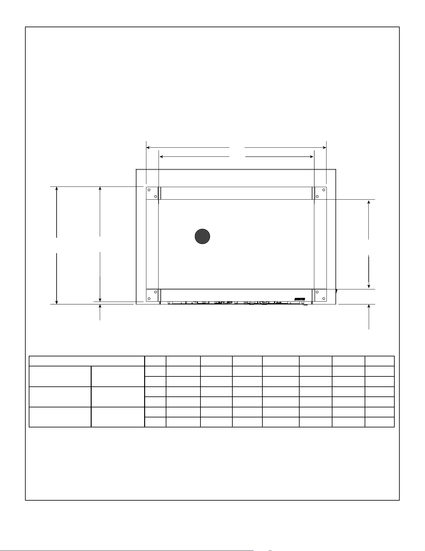
12
Majestic • TRILLIANT25IN/IL, TRILLIANT30IN/IL, TRILLIANT35IN/IL Installation Manual • 2571-980 Rev. G • 6/24
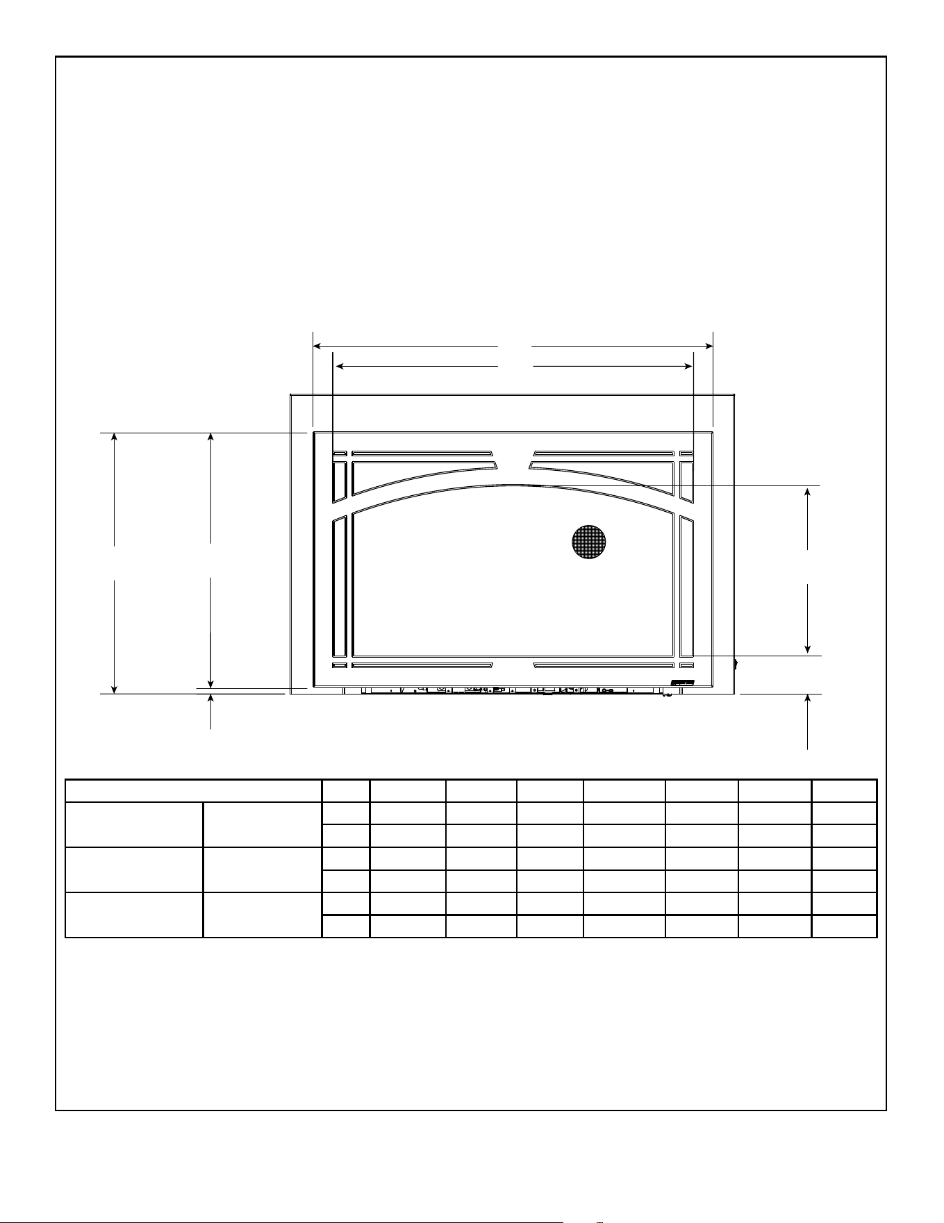
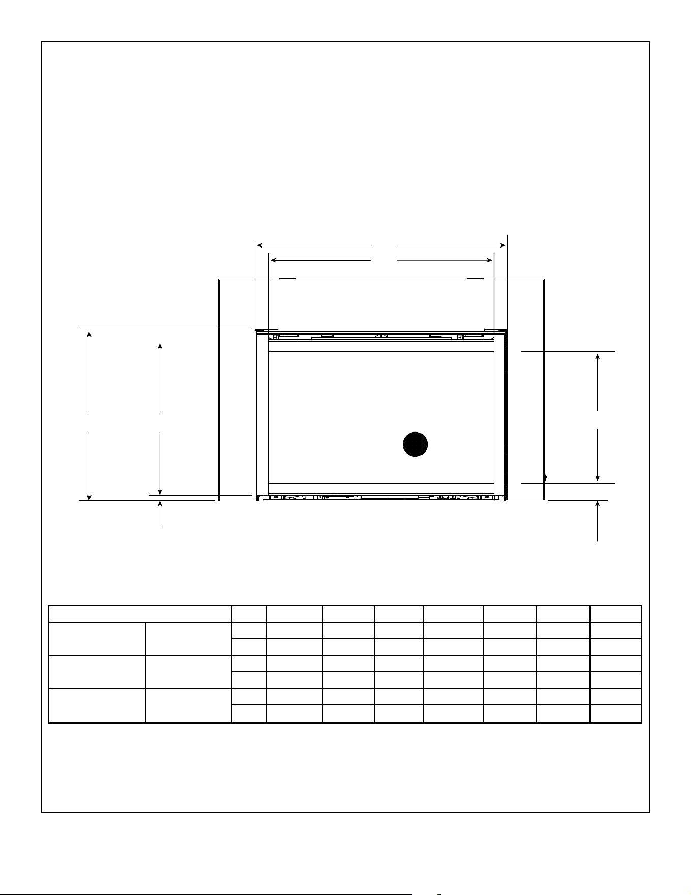
Figure 3.5 Decorative Barrier Front Dimensions - Mission Full View
DECORATIVE BARRIER FRONT - MISSION FULL VIEW
A B C D E F G
TRILLIANT25I MFV-TRI25
in. 26-1/4 14-1/2 3 31-1/4 20 19-1/2 1/2
mm 667 368 76 794 508 495 13
TRILLIANT30I MFV-TRI30
in. 31-1/4 18 3 36-1/4 23-1/2 23 1/2
mm 794 457 76 921 597 584 13
TRILLIANT35I MFV-TRI35
in. 36-1/4 21-1/2 3 41-1/4 27 26-1/2 1/2
mm 921 546 76 1048 686 673 13
F
D
A
B
C
G
E
*
*
NOTICE: 1/2 inch gap must be maintained
or components will overheat.
13
Majestic • TRILLIANT25IN/IL, TRILLIANT30IN/IL, TRILLIANT35IN/IL Installation Manual • 2571-980 Rev. G • 6/24
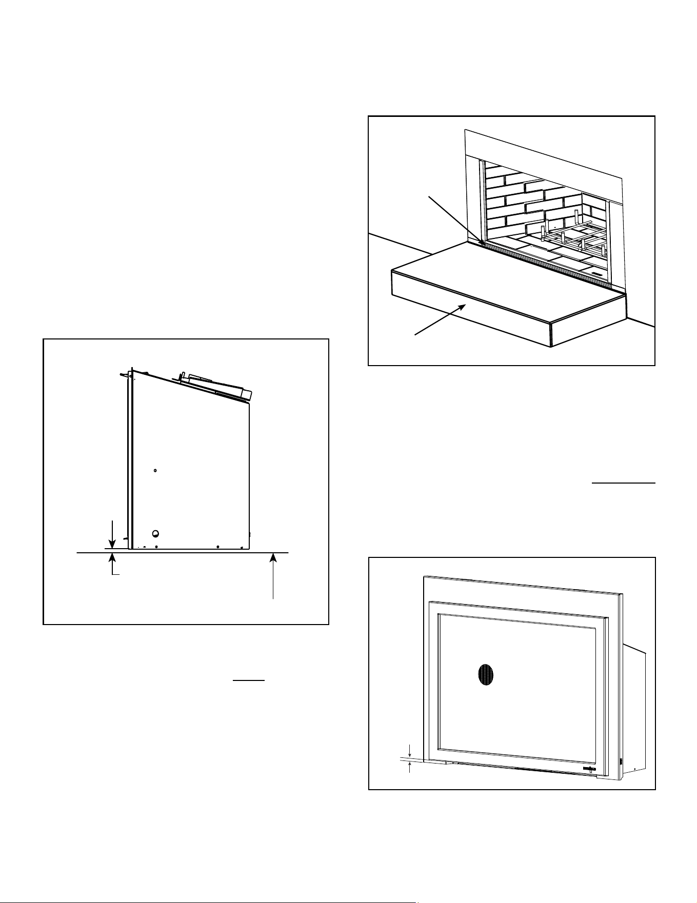
Figure 3.6 Decorative Barrier Front Dimensions - Inside Fit
DECORATIVE BARRIER FRONTS - INSIDE FIT
A B C D E F G
TRILLIANT25I INFIT-25
in. 22-5/8 12-9/16 1-7/8 25-5/8 17 16-1/2 1/2
mm 575 319 48 651 432 420 13
TRILLIANT30I INFIT-30
in. 27-5/8 16-1/16 1-7/8 30-5/8 20-1/2 20 1/2
mm 702 408 48 778 521 508 13
TRILLIANT35I INFIT-35
in. 32-5/8 19-9/16 1-7/8 35-5/8 24 23-1/2 1/2
mm 829 497 48 905 610 597 13
F
D
A
B
C
G
E
*
*
NOTICE: 1/2 inch gap must be maintained
or components will overheat.
14
Majestic • TRILLIANT25IN/IL, TRILLIANT30IN/IL, TRILLIANT35IN/IL Installation Manual • 2571-980 Rev. G • 6/24
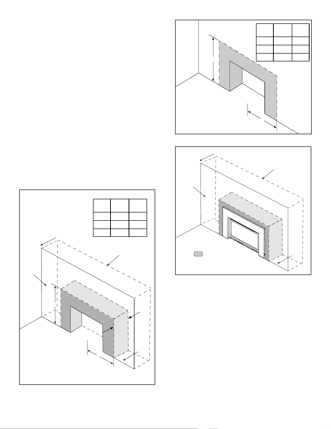
B. Minimum Fireplace Opening
Minimum replace opening requirements for a standard 3/4
inch deep surround are shown in Figure 3.9. For smaller
openings, a custom surround is available.
WARNING! Risk of Fire or Burns! Provide adequate
clearance around air openings and for service access.
Due to high temperatures, the appliance should be locat-
ed out of trafc and away from furniture and draperies.
For Installation into a Zero Clearance Wood burning re-
place:
• The brick (refractory), glass doors, screen rails, screen
mesh and log grates can be removed from a factory
built rebox in order to gain minimum gas insert opening
requirements.
• Any smoke shelves, shields and bafes may be removed
from the factory built rebox if attached with mechanical
fasteners.
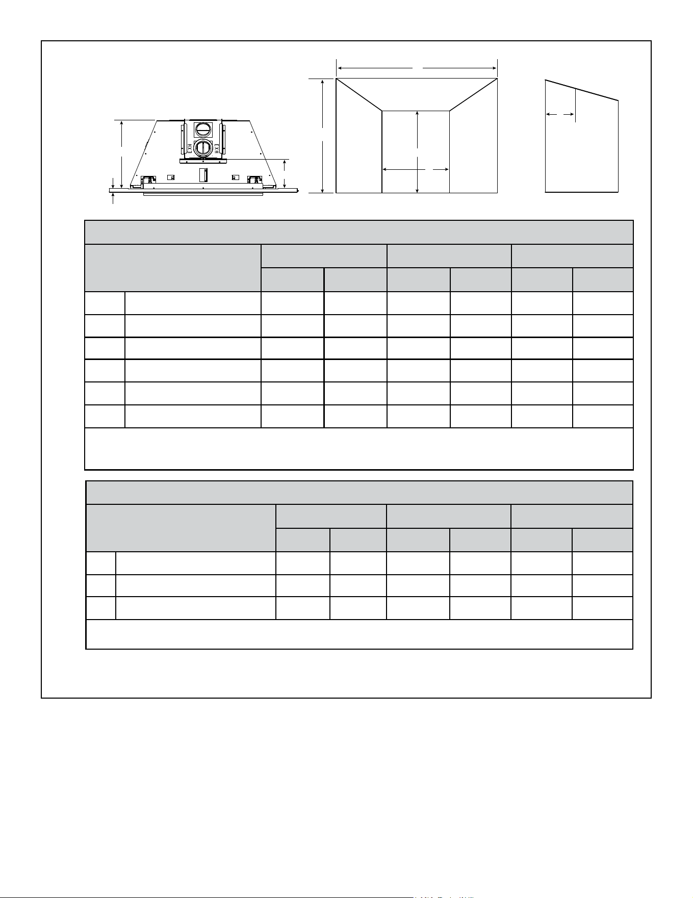
Figure 3.7 Solid Fuel Floor Clearance
SIDE VIEW
MINIMUM 1/4 IN. REQUIRED
COMBUSTIBLE FLOOR UNDERNEATH APPLIANCE
• The appliance may not be placed directly on the base of
the outer wrap, a 1/4 inch airspace MUST be provided
between the insert and the oor of the outer wrap. Use
the leveling legs to raise the insert a minimum of 1/4 inch.
The original replace may never be returned to solid
fuel in this condition. The sidewalls and top structure
of the rebox may not be altered with the exception of
removable bafes and dampers.
1/2 in.
NOTICE: 1/2 inch gap must be maintained or components
will overheat.
Figure 3.9 Minimum Required 1/2 in. Gap
• Cutting of any sheet metal parts of the replace in which
the gas replace insert is to be installed is prohibited,
except the oor and front lip as tested for and as noted
above. See Section 4.C for gas line exception.
• A minimum 1/4 inch gap from the bottom of the appliance
to the metal oor of the solid fuel rebox is REQUIRED.
See side view in Figure 3.7.
• Manufactured gas inserts can be installed as a zero
clearance wall extension appliance. See Section 3.C
for clearance detail.
• The metal oor of the solid fuel rebox may be removed
to facilitate the installation of the insert.
• A metal lip protuding above the hearth pad of the solid
fuel rebox may be removed. See Figure 3.8.
Figure 3.8 Solid Fuel Firebox
HEARTH PAD
ACCEPTABLE
TO REMOVE
15
Majestic • TRILLIANT25IN/IL, TRILLIANT30IN/IL, TRILLIANT35IN/IL Installation Manual • 2571-980 Rev. G • 6/24
Figure 3.10 Firebox Opening - Standard Surround - 3/4 in.
In addition to these dimensions, also reference Section 3.D and 3.E.
TOP VIEW
FRONT VIEW SIDE VIEW
*Unit depth is measured to the back of the surround to give the depth needed for installation.
F
D
C
A
B
F
E
7/8 in.
(Standard)
2 in.
(Deep)
MINIMUM FIREBOX OPENING
Location
25 inch 30 inch 35 inch
Inches Millimeters Inches Millimeters Inches Millimeters
A Opening Width - Rear 15-1/8 384 20-1/8 511 25-1/8 638
B Opening Width - Front 26-5/8 676 31-5/8 803 36-5/8 930
C Opening Height - Front 17-5/16 439 21 533 24-1/4 616
D Opening Height - Rear 15-1/4 387 19-3/16 487 21-11/16 551
E* Unit Opening Depth 15 381 15 381 15 381
F Venting Depth - Front 7-5/8 194 7-5/8 194 7-5/8 194
Note: Dimensions assume 1/4 inch clearance on all sides.
Note: If exhaust collar on insert and replace damper do not line up, add 4 inches (102 mm) to minimum replace
height for bends in vent pipe.
Custom Surrounds
Custom surrounds are available. See your dealer for information. Standard surrounds are 3/4 inches deep. Custom
surrounds are available up to 3 inches deep. A 3 inch deep surround would reduce the unit opening depth (E*) by 2-1/4
inches (3 in. - 3/4 in. = 2-1/4 in).
On Site Custom Surrounds
On site custom surrounds are available. See your dealer for information. On site custom surrounds are ush and have
no depth. A ush surround would increase the unit opening depth (E*) by 3/4 inch.
2 INCH DEEP SURROUND MINIMUM FIREBOX OPENING
Location
25 inch 30 inch 35 inch
Inches Millimeters Inches Millimeters Inches Millimeters
B Alternate Opening Width - Front 26 660 31 787 36 914
C Alternate Opening Height - Front 17-5/16 440 21 533 24-1/4 616
E Alternate Unit Opening Depth 14 356 14 356 14 356
Note: 2 inch deep surrounds, in medium size black nish have been created as standard accessory.
Sku Names: MI30-4230D-BK, MI35-4432D-BK
16
Majestic • TRILLIANT25IN/IL, TRILLIANT30IN/IL, TRILLIANT35IN/IL Installation Manual • 2571-980 Rev. G • 6/24
FLOOR
x
Y
NON-COMBUSTIBLE ZONE
C
L
EXISTING MASONRY WALL
NEW WALL
FACE
WALL EXTENSION
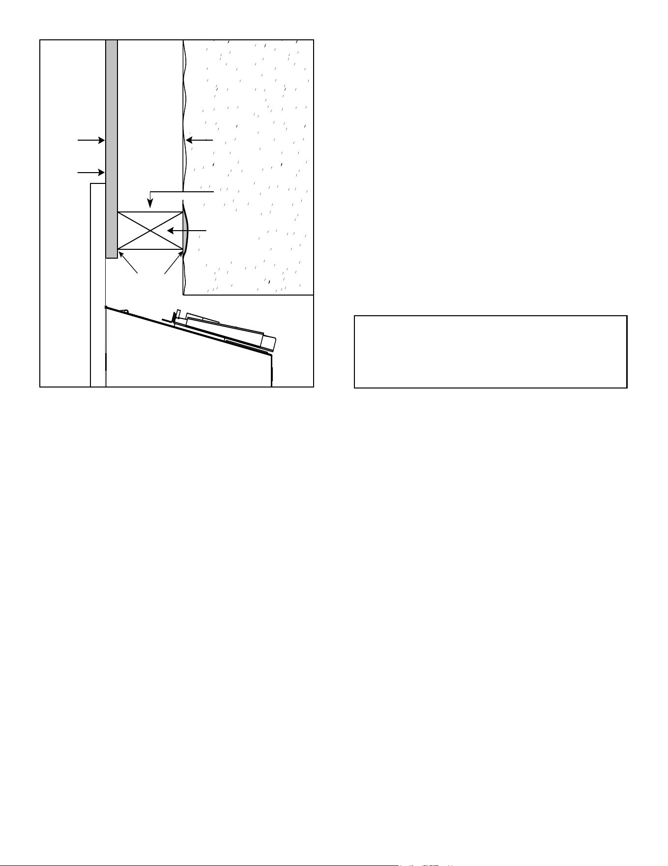
C. Zero Clearance Wall Extension
Figure 3.12 Non-Combustible Facing Requirement
Figure 3.13 Non-Combustible Framing / Facing Requirement
WARNING! Risk of Fire! Comply with all minimum clear-
ances to combustibles as specied. Framing or nishing
material closer than the minimums listed must be construct-
ed entirely of noncombustible materials (i.e., steel studs,
concrete board, etc).
Combustible facings must not extend behind the insert
surround. See Section 1.E and 1.F.
Non-Combustible Materials Specication
Material which will not ignite and burn. Such materials are
those consisting entirely of steel, iron, brick, tile, concrete,
slate, glass or plasters, or any combination thereof.
Materials that are reported as passing ASTM E 136,
Standard Test Method for Behavior of Materials in a
Vertical Tube Furnace at 750 ºC.
• Facing and/or nishing materials must not interfere with
air ow through decorative barrier fronts.
• Facing and/or nishing materials must never overhang
into the glass opening.
• Observe all clearances when applying combustible
materials.
• Maximum depth of wall extension is 12 inches. This
may be limited by the ex pipe’s ability to connect to the
starting collar.
• Covering combustible materials with non-combustible
materials does not qualify material as non-combustible.
WARNING! Risk of Fire! DO NOT apply combustible
materials beyond the minimum clearances. Comply with
all minimum clearances to combustibles as specied in
this manual. Overlapping materials could ignite and will
interfere with proper operation of decorative barrier fronts.
FLOOR
x
Y
NON-COMBUSTIBLE ZONE
C
L
UNIT
X
(min)
Y
(min)
25 in. 31 52
30 in. 33-1/2 56
35 in. 36 60
UNIT
X
(min)
Y
(min)
25 in. 31 52
30 in. 33-1/2 56
35 in. 36 60
A non-combustible wall extension can be used to cover
an existing masonry surface. Wall extensions are typically
used to improve cosmetics.
Surrounds MUST overlap wall extension.
FLOOR
EXISTING MASONRY WALL
NEW WALL
FACE
WALL EXTENSION
NON-COMBUSTIBLE ZONE
Figure 3.11 Non-Combustible Framing Requirement
12 in. max.
DEPTH
X - Minimum - measure from
center of rebox opening.
Y - Minimum - measure from
the bottom of the appliance.
X - Minimum - measure from
center of rebox opening.
Y - Minimum - measure from
the bottom of the appliance.
17
Majestic • TRILLIANT25IN/IL, TRILLIANT30IN/IL, TRILLIANT35IN/IL Installation Manual • 2571-980 Rev. G • 6/24
FACING
STEEL STUD
END VIEW
MASONRY
WALL
STEEL STUD
SIDE VIEW
SEAL
TRANSITION
12 in.
MAXIMUM
APPLIANCE
SEAL STEEL
STUDS
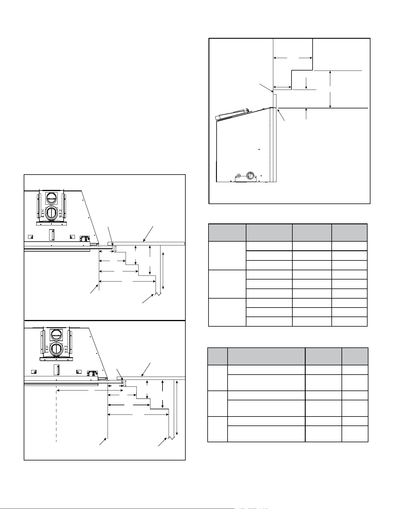
Figure 3.14 Transition Sealing Detail for Wall Extensions (Side View)
Painting
If desired nishing includes a painted wall, a high-quality
100% acrylic latex paint with a high-quality latex primer
base coat are recommended around the appliance to limit
discoloration. Oil-based or standard acrylic paints may
be more prone to discoloration due to heat exposure.
Drywall Joint-Crack Prevention and Repair
Drywall joints around the replace will be affected by ex-
posure to elevated temperatures, along with other envi-
ronmental, structural factors due to new construction, and
methods used to install and nish the drywall. If a crack
does emerge adjacent to the replace, it can be perma-
nently repaired by lling it with a paintable latex caulk,
followed by repainting.
Some movement of the screws used to secure the non-
combustible board to the appliance/surround framing is
expected. If a blemish begins to show over a screw head,
sand the surface to remove the blemish and repaint.
Wall Extension
Wall extension must be sealed to existing masonry
wall. See Figure 3.14. Framing studs may not sit ush
against existing masonry wall. In order to keep heat
from escaping behind the wall this transition must be
sealed. Also, slots in steel studs must be sealed.
• Seal with a high temperature silicone 300 °F.
and / or
• Packing insulation into voids between the masonry wall
and steel studs is acceptable.
Note: Combustible materials may be used to seal wall
extension to existing masonry wall as long as it is out-
side the non-combustible zone.
NOTE: Concealed sections of 3 in. ex pipe must
be contained inside existing masonry replace
ue vent or installed into an existing wood burn-
ing vent system.
18
Majestic • TRILLIANT25IN/IL, TRILLIANT30IN/IL, TRILLIANT35IN/IL Installation Manual • 2571-980 Rev. G • 6/24
D. Mantel, Wall Projections, & Hearth
Extensions
WARNING! Risk of Fire! Comply with all minimum clear-
ances to combustibles as specied. Framing or nishing
material closer than the minimums listed must be construct-
ed entirely of noncombustible materials (i.e., steel studs,
concrete board, etc).
Clearance to combustible material under the insert is 1/4
inch (6 mm).
• Use leveling legs to raise insert minimum 1/4 inch (6
mm) above combustible material or outer wrap of factory
built rebox.
Combustible facings must not extend behind the insert
surround. For non-combustible material specications
refer to Section 1.E and 1.F.
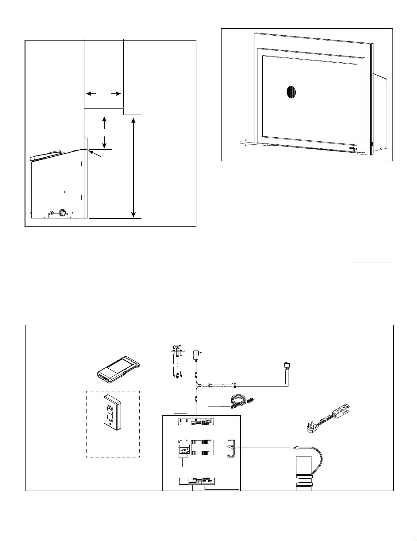
Mantel Legs or Wall Projections
INTERIOR WALL
TOP VIEW
MANTEL LEG OR WALL PROJECTIONS
SURROUND OPENING
∞
18 in.
12 in.
12 in.
1/4 in. GAP
6 in.
6 in.
4 in.
2 in.
Figure 3.15 Clearances to Mantel Legs or Wall Projections
(Acceptable on both sides of surround opening)
Non-Combustible
Combustible
INTERIOR WALL
TOP VIEW
MANTEL LEG OR
WALL PROJECTIONS
SURROUND OPENING
1/4 in. Gap
A
*
C
L
*SEE TABLE
1 or 2
∞
18 in.
12 in.
12 in.
6 in.
6 in.
4 in.
2 in.
Figure 3.16 Minimum Vertical and Maximum Horizontal
Dimensions- Non-Combustible
Mantels or Wall Projections - Non-Combustible
1/4 in. gap
SURROUND
OPENING
6 in.
12 in.
12 in.
*B
*SEE TABLE
1 or 2
Note: Measurement is taken from top of the surround
opening.
Unit Size
Surround
Model
A B
25 in.
MI25-3523 17-15/16 in. 6-1/16 in.
MI25-3726 18-15/16 in. 9-1/16 in.
MI25-3928 19-15/16 in. 11-1/16 in.
30 in.
MI30-4027 20-7/16 in. 6-9/16 in.
MI30-4230 21-7/16 in. 9-9/16 in.
MI30-4432 22-7/16 in. 11-9/16 in.
35 in.
MI35-4229 21-7/16 in. 5-1/16 in.
MI35-4432 22-7/16 in. 8-1/16 in.
MI35-4832 24-7/16 in. 8-1/16 in.
Table 1 Mantel Leg or Wall Projection Minimum Dimension
needed when Installing a Standard Surround
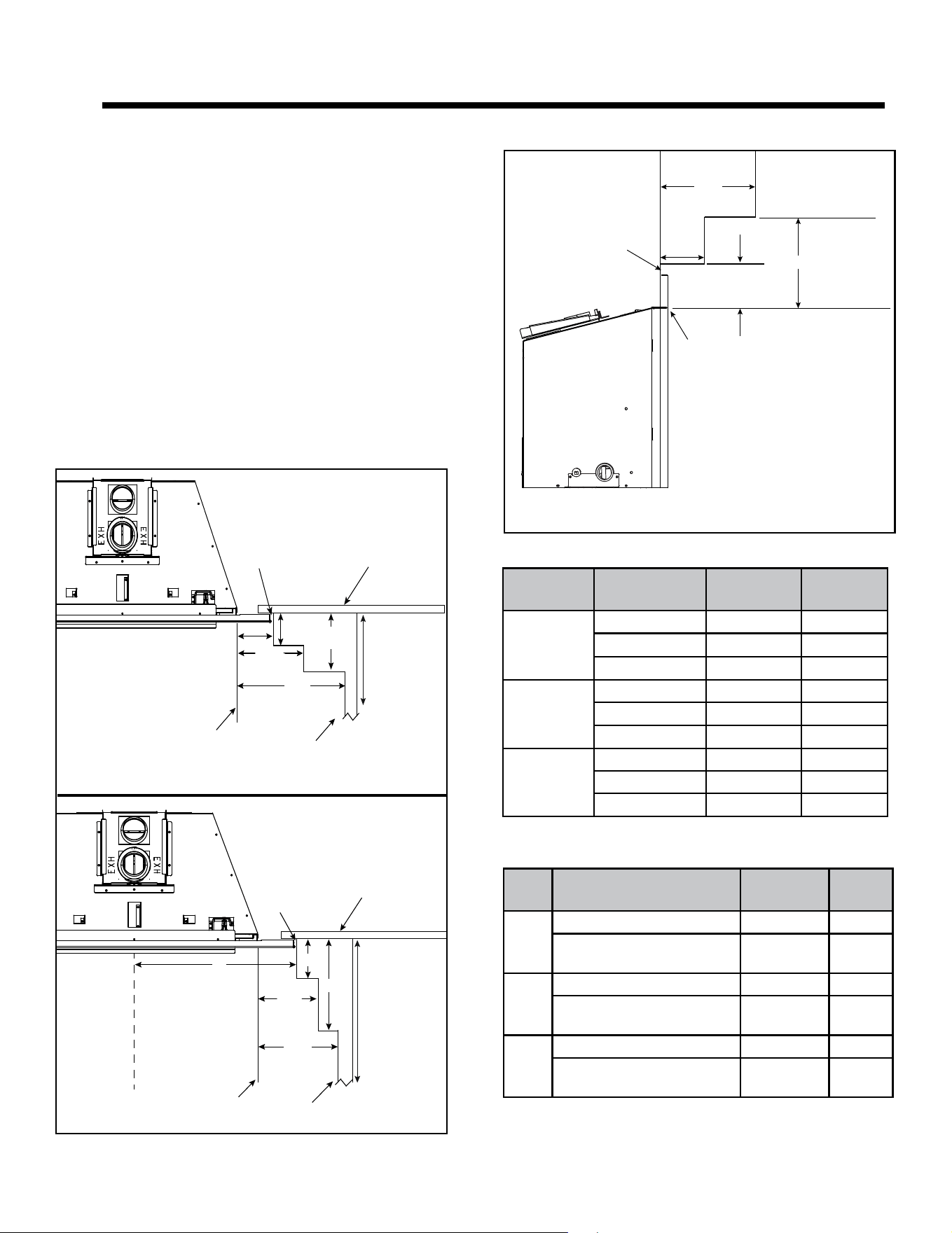
Note: All numbers in Tables 1 and 2 include the 1/4 in. gap on
surround edge.
Unit
Size
Front Model A B
25 in.
INFIT 14-5/8 in. 1-1/4 in.
FA-TRI, TA-TRI,
MFV-TRI, CSFI25
16-1/16 in. 2-1/2 in
30 in.
INFIT 17-1/8 in. 1-1/4 in.
FA-TRI, TA-TRI,
MFV-TRI, CSFI30
18-9/16 in. 2-1/2 in
35 in.
INFIT 19-3/4 in. 1-1/4 in.
FA-TRI, TA-TRI,
MFV-TRI, CSFI35
21-1/16 in. 2-1/2 in
Table 2 Mantel Leg or Wall Projection Minimum Dimension
needed when Installing a Custom Surround. Front Model
Determines the Minimum Size of the Custom Surround
19
Majestic • TRILLIANT25IN/IL, TRILLIANT30IN/IL, TRILLIANT35IN/IL Installation Manual • 2571-980 Rev. G • 6/24
E. Hearth Extension / Vinyl Flooring
1/2 in.
Figure 3.18 Minimum Required 1/2 in. Gap to Bottom of Front
Mantels - Combustible
Figure 3.17 Minimum Vertical and Maximum Horizontal
Dimensions - Combustible
Measurement to bottom
of appliance:
= 29-1/4 in. (25")
= 32-3/4 IN. (30")
= 36-1/4 IN. (35")
Measurement
from surround
opening.
12 in.
12 in.
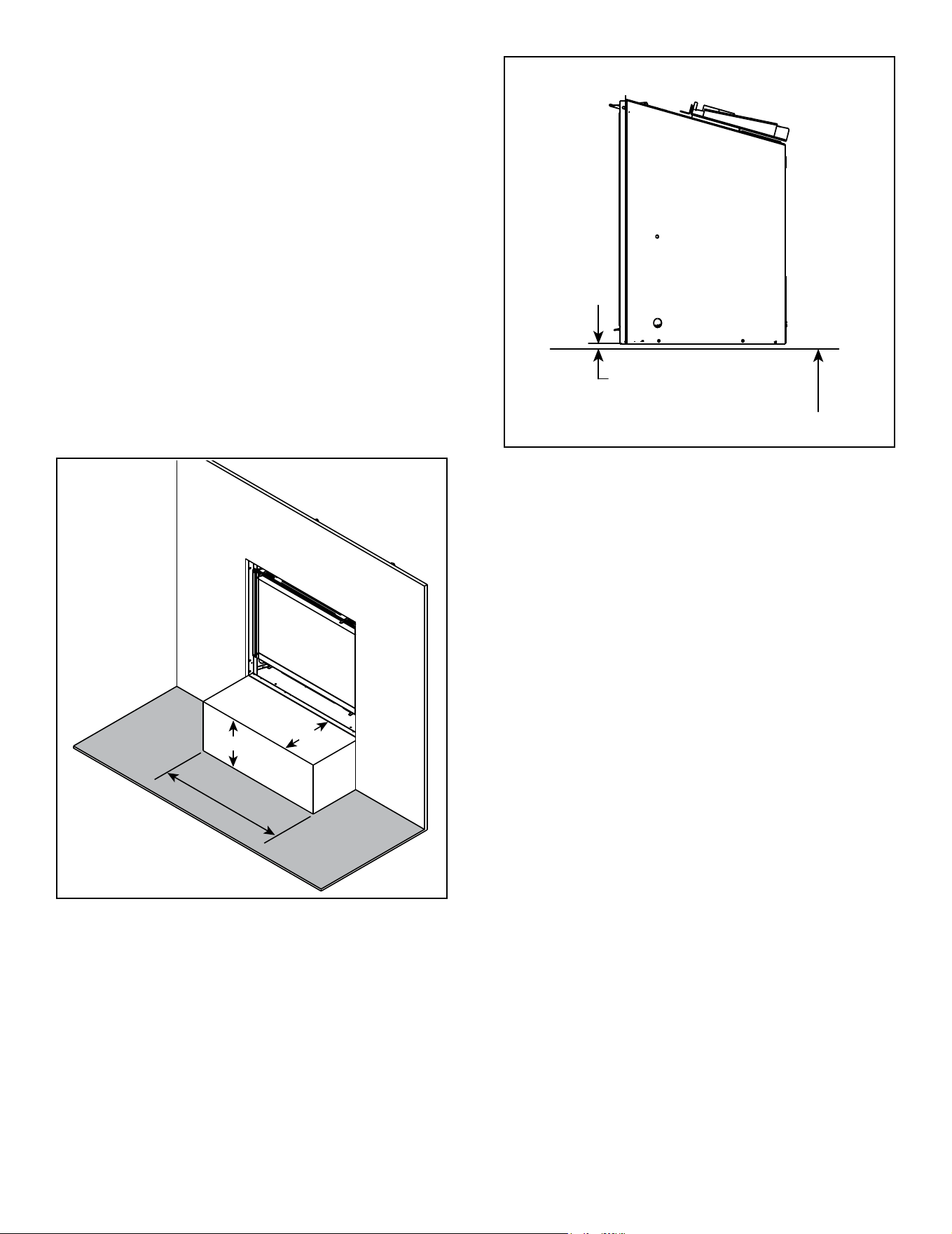
• All ooring and hearth material must remain below the
bottom of the surround. See Figure 3.19.
• Combustible ooring may be located in front of
the appliance. See Figure 3.20 for vinyl ooring
recommendations.
• 1/2 inch gap under the bottom of the front must be
maintained. See Figure 3.18.
• A minimum 1/4 inch gap from the bottom of the appliance
to the metal oor of the solid fuel rebox is REQUIRED.
See side view in Figure 3.21.
• Combustible flooring underneath the appliance is
acceptable with a 1/4 inch gap. See Figure 3.21.
FLAME
SENSE
IGNITER
TO POWER
CORD
110-120 VAC
FAN 110-120 VAC
RF MODULE
6V TRANSFORMER
PLUG
I
S
6 PIN
BRN
ORANGE
(PILOT)
GREEN
(MAIN)
IFT-RC400
REMOTE
CONTROL
IFT-RC150
WIRELESS
WALL SWITCH
(OPTIONAL)
APPLIANCE
ON/OFF
CONTROL
BRN
BLK
WIRE ASSEMBLY
BLK
RED
BLK
(OPTIONAL)
TO POWER CORD 110-120 VAC
(OPTIONAL)
ORANGE
WHITE
BACK VIEW
TOP VIEW
FRONT VIEW
SIDE
VIEW
POWER CORD
2550-013 (NG)
2550-014 (LP)
2326-131
2326-152
2326-130
2326-150
2179-300
2326-120
2166-302 (NG)
2166-303 (LP)
2326-132
GFK-160A
WSK-21-W
2159-310
2201-024
LIGHT WIRE
ASSEMBLY
2532-017
2201-150
HALOGEN BULBS (X 2)
NOT AN OPTION WITH 25 in. MODELS
2206-299
* MODULE RESET SWITCH
(LOCATED ON SURROUND)
* Reset switch must be installed
and in the “ON” position for
appliance to operate.
2187-198
BATTERY
PACK
2326-142
2532-301
Figure 3.19 Flooring & Hearth Material
20
Majestic • TRILLIANT25IN/IL, TRILLIANT30IN/IL, TRILLIANT35IN/IL Installation Manual • 2571-980 Rev. G • 6/24
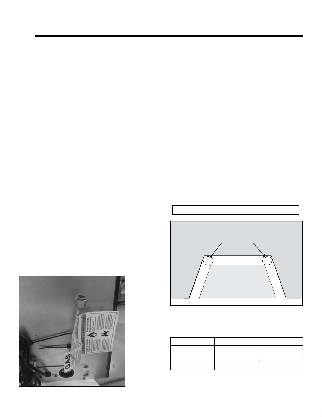
Figure 3.21 Solid Fuel Floor Clearance
SIDE VIEW
MINIMUM 1/4 IN. REQUIRED
COMBUSTIBLE FLOOR UNDERNEATH APPLIANCE
12 IN. MIN.
APPLIANCE WIDTH MIN.
12 IN. MIN.
VINYL
Figure 3.20 Vinyl Flooring Recommendations
Vinyl Flooring
Vinyl ooring is sensitive to heat. To avoid damage to
the vinyl ooring, a 12 inch minimum x 12 inch mini-
mum hearth is recommended when using vinyl ooring
up to the wall. See Figure 3.20. If no hearth is used,
it is recommended to provide a minimum of 24 inches
of clearance in front of the appliance to the vinyl oor-
ing OR the bottom of the appliance should be raised a
minimum of 24 inches off of the oor to allow the vinyl
ooring to be installed up to the wall.
NOTICE: Clearances that do not meet the minimum
guidelines could result in damage or buckling to the vinyl
ooring and is done at the installer’s risk.
Hearth and Home Technologies does not recommend
adhesive based vinyl ooring products due to thermal ex-
pansion during operation. Floating style ooring can be
used, but it will reach temperatures up to 110 °F (based
on ambient temperature of 70 °F). Consult the manufac-
turer’s ooring specications to ensure compatibility.
21
Majestic • TRILLIANT25IN/IL, TRILLIANT30IN/IL, TRILLIANT35IN/IL Installation Manual • 2571-980 Rev. G • 6/24
4 4
Installation Preparation
Prepare the existing solid fuel masonry or factory built
non-combustible rebox for installation.
A. Cleaning
Prior to installing the gas insert:
• Ensure that the woodburning replace cavity is clean
and free of ash, soot, and other debris.
B. Flue Damper
Fully lock the solid fuel replace’s ue damper in the open
position, OR completely remove it.
C. Gas Line
Note: If the factory-built replace has no gas access hole
provided, an access hole of 1 inch (25 mm) diameter or
less may be drilled through the lower sides or bottom of the
rebox in a proper workmanship - like manner. This access
hole must be plugged with non-combustible insulation after
the gas supply line has been installed.
• If the gas access hole of the factory-built replace is not
accessible or prohibits the installation due to its location,
an access hole may be drilled through the lower side,
back or bottom of rebox.
• The lower sides, back, or bottom is considered the lower
half of the factory-built rebox.
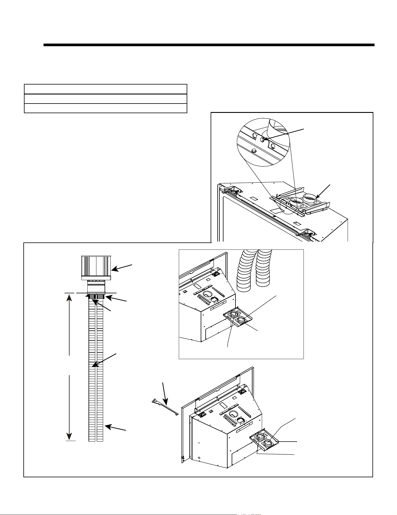
• Install gas line to the factory provided ex line. See
Figure 4.1.
• Check local codes and gas line sizing requirements
following NFPA54. See Section 7.
• It is recommended that extra length of gas line be
installed within the existing wood burner or masonry
replace to allow removal of the insert for future servicing
needs.
D. Fireplace Conversion Notice
The replace conversion notice is included in the appliance
manual bag. Permanently attach the label with the follow-
ing warning to the inside lower back of the replace rebox
into which the insert is being installed. Silicone or mechani-
cal fasteners may be required to properly secure the label.
WARNING! Risk of Fire! This replace has been con-
verted for use with a gas replace insert only and cannot
be used for burning wood or solid fuels unless all original
parts have been replaced, and the replace re-approved
by the authority having jurisdiction.
E. Electrical Outlet Box
An outlet box may be installed in a bottom back corner of
the existing solid fuel masonry or factory-built replace
to power the appliance. Each unit ships standard with a
cord assembly to permit blowers or other optional acces-
sories to be used. The accessories plug into the new out-
let box or may be routed out onto the hearth to a nearby
outlet.
ELECTRICAL OUTLET LOCATIONS
MASONRY
MASONRY
APPLIANCE
RECOMMENDED
NOTICE: DO NOT wire 110-120 VAC to wall switch.
Figure 4.2 Electrical Outlet Detail
Figure 4.1
Appliance Size Left Side Right Side
25 in. 10 ft. 6 in. 8 ft.
30 in. 10 ft. 3 in. 7 ft. 6 in.
35 in. 10 ft. 7 ft.
Appliance Cord Length (approximate)
22
Majestic • TRILLIANT25IN/IL, TRILLIANT30IN/IL, TRILLIANT35IN/IL Installation Manual • 2571-980 Rev. G • 6/24
WARNING! Risk of Fire/Explosion/Asphyxiation! Do
NOT connect this gas appliance to a chimney ue serving
a separate solid fuel or gas burning appliance.
• Could impair safe operation of this appliance or other
appliances connected to the ue.
• Vent this appliance directly outside.
• Use separate vent system for this appliance.
A. Vent Limits
The abbreviations listed in this vent table key are used in
the vent diagrams.
Description
Minimum Vertical Run Length 10 ft.
Maximum Vertical Run Length 50 ft.
CAUTION! ALL vent specications MUST be followed.
This product is tested and listed to these specications.
Appliance performance will suffer if specications are not
followed.
5 5
Installing Vent Pipe and Appliance
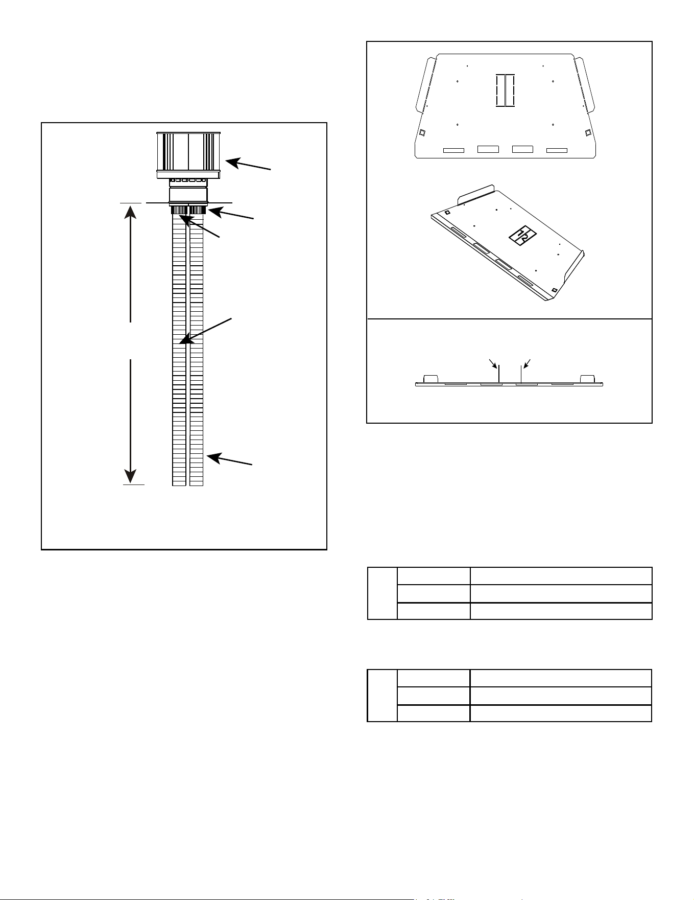
EXHAUST
AIR
VENT PIPE
EXHAUST STARTING COLLAR
COLLAR SLIDE PLATE ASSEMBLY
EXHAUST STARTING COLLAR
INLET AIR STARTING COLLAR
COLLAR SLIDE PLATE ASSEMBLY
INLET AIR STARTING COLLAR
INLET AIR
VENT PIPE
V = 10 FT. MINIMUM
50 FT. MAXIMUM
NOTE: TO ACHIEVE OPTIMUM PERFOR-
MANCE OF INSERT, MINIMIZE OR AVOID
BENDS IN EXHAUST VENT PIPE.
EXHAUST
COLLAR
INLET
COLLAR
MULTI-PURPOSE TOOL
TERMINATION
CAP
(SEE FIGURE 2.1)
Figure 5.1
BE SURE SLIDE
PLATE SCREW IS
FULLY TIGHTENED.
COLLAR SLIDE
PLATE ASSEMBLY
INSTALLED.
23
Majestic • TRILLIANT25IN/IL, TRILLIANT30IN/IL, TRILLIANT35IN/IL Installation Manual • 2571-980 Rev. G • 6/24
B. Using Vertical Restrictor
EXHAUST
AIR
VENT PIPE
TERMINATION
CAP
INLET AIR
VENT PIPE
V = 10 FT. MINIMUM
50 FT. MAXIMUM
NOTE: TO ACHIEVE OPTIMUM PERFOR-
MANCE OF INSERT, MINIMIZE OR AVOID
BENDS IN EXHAUST VENT PIPE.
EXHAUST
COLLAR
INLET
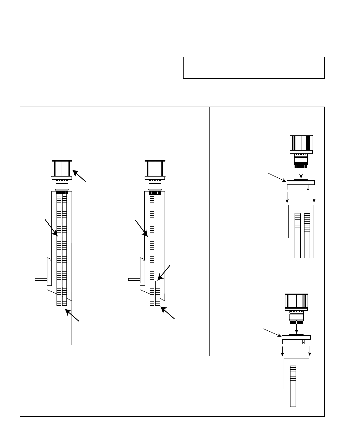
COLLAR
V=
10 ft. - 25 ft. No adjustment needs to be done.
26 ft. - 35 ft. Open 1 restrictor opening.
36 ft. - 50 ft. Open both restrictor openings.
1 2
FRONT VIEW SHOWS RESTRICTORS IN THE OPEN POSITION AND BENT AT 90º
RESTRICTOR DOORS
Figure 5.3 Firebox Bafe
To open restrictors, push the restrictor doors upward.
The restrictor doors should be bent at a 90°. See Figure
5.3.
Figure 5.2 Min. / Max. Venting Requirement
When 20-25+ feet of vertical venting is used, vertical
restrictors will need to be adjusted. See Figure 5.2 and
5.3.
Opening restrictors will help reduce cold start or sooting
issues (cycling).
Appliance - 25 in. & 30 in.
V=
10 ft. - 20 ft. No adjustment needs to be done.
21 ft. - 35 ft. Open 1 restrictor opening.
36 ft. - 50 ft. Open both restrictor openings.
Appliance - 35 in.
24
Majestic • TRILLIANT25IN/IL, TRILLIANT30IN/IL, TRILLIANT35IN/IL Installation Manual • 2571-980 Rev. G • 6/24
Note: The LINK-DV4-30B and LINKSQ-DV4-30 systems
REQUIRE this insulation.
To prevent odors and cold air drafts, it may be necessary to
place non-combustible insulation or eld fabricated metal
plates around the vent pipe ues as they go through the
damper.
Figure 5.4
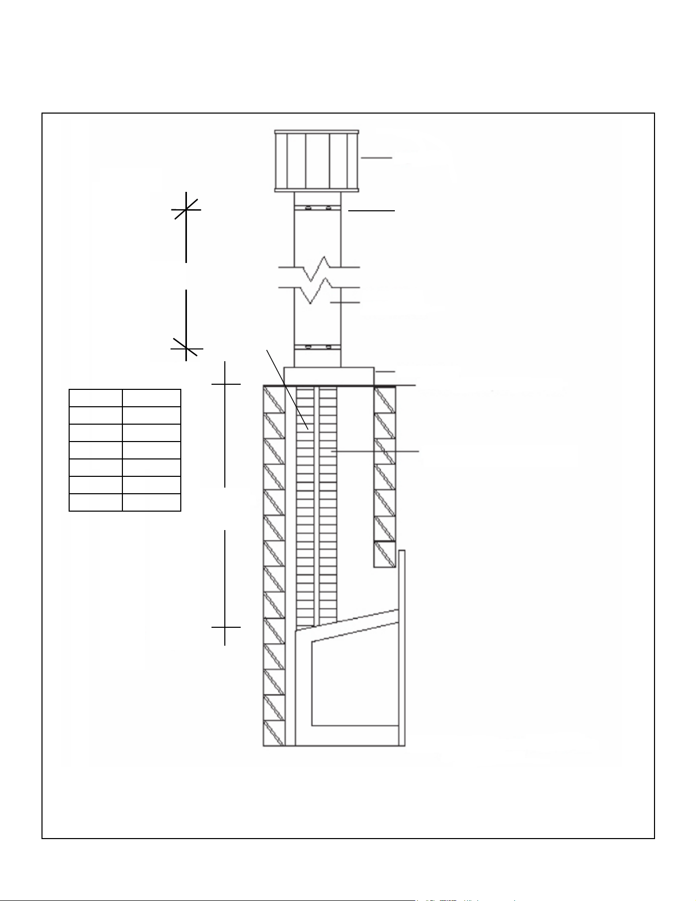
C. Venting Components
CAUTION! Risk of Cuts/Abrasions/Flying Debris.
Wear protective gloves and safety glasses during instal-
lation. Sheet metal edges are sharp.
The vertical vent termination system installed on this model
includes:
• One length of 3-inch exible vent pipe for exhaust air
(included with vent kit).
• One length of 3-inch exible vent pipe for combustion
air (included with vent kit).
• One vertical termination cap (included with vent kit).
EXHAUST
AIR
VENT PIPE
TERMINATION
CAP
LINK-DV30B
LINKSQ-DV30
Installation*
LINK-DV4-30B
LINKSQ-DV4-30
Installation**
INLET AIR
VENT PIPE
WARNING:
DO NOT BLOCK
THIS PIPE END!
INLET AIR
VENT PIPE
EXHAUST
AIR
VENT PIPE
OPTIONAL LINK-ZC-ADPB
FOR USE WITH CLASS A
WOODBURNING PIPE
LINK-DV4-30B
LINKSQ-DV4-30
Installation**
Masonry
Factory Built
Wood Burning
Remove 18 inch x 18 inch
ashing on cap by removing
3 screws. Connect both the
LINK-ZC-ADPB to Class A
Pipe and the termination cap
to the LINK-ZC-ADPB with
self tapping screws.
OPTIONAL LINK-ZC-ADPB
FOR USE WITH CLASS A
WOODBURNING PIPE
LINK-DV30B
LINKSQ-DV30
Installation*
Note: Untwist the
pipe while extend-
ing it, to achieve
full 30’ length.
OR
*LINK-DV30B/LINKSQ-DV30: This installation may perform better and allow less cold air inltration in
negative pressure settings.
**LINK-DV430B/LINKSQ-DV4-30:
• This installation may be more susceptible to cold air inltration and the effects of negative pressure
on the appliance’s performance.
• Depending on the chimney cleanliness, consider using the full length intake so as to lessen
the possibility of sense rod contamination and ame rectication issues.
Note: Untwist the
pipe while extend-
ing it, to achieve
full 30’ length.
OR
25
Majestic • TRILLIANT25IN/IL, TRILLIANT30IN/IL, TRILLIANT35IN/IL Installation Manual • 2571-980 Rev. G • 6/24
Figure 5.5 Optional SLP Venting Conguration - Vertical Termination
SLP-TVHW
SLP 6-5/8 Ø
COLINEAR TO COAXIAL
ADAPTER DV-46DVA-GK
FLEXIBLE FLUE
SLP
3 in
Flex
Must adhere to pipe clearances.
NOTE: 3 in. sections
of flex pipe must be
enclosed to existing
masonry replace ue
vent or installed into an
existing wood burning
vent system.
Four 45 degree elbows can be used in the vertical section of SLP venting to avoid structural members such as
oor joist or trusses. Maximum total vent run is 50 ft. 90 degree elbows may NOT be used.
D. Connecting to SLP
Terminating horizontally is not allowed.
Vertical terminations are measured to top of chimney.
This appliance is listed for use with LINK-DV systems
and components only. It is permissible to extend venting
above existing chimney (within specied maximum ver-
tical limits) using SLP series 6-5/8 inch gas direct-vent
pipe. Connection is made using DV-46DVA-GK.
LINK-DV30B/LINKSQ-DV30: This installation
may perform better and allow less cold air in-
ltration in negative pressure settings.
LINK-DV430B/LINKSQ-DV4-30:
• This installation may be more susceptible to
cold air inltration and the effects of negative
pressure on the appliance’s performance.
• Depending on the chimney cleanliness,
consider using the full length intake so
as to lessen the possibility of sense rod
contamination and ame rectication
issues.
Flex Min SLP
5 ft. 8 ft.
6 ft. 7 ft.
7 ft. 6 ft.
8 ft. 5 ft.
9 ft. 4 ft.
10 ft. N/A
Up to four 45 degree elbows may be used as long as the minimum venting requirements are met per the above
chart.
INLET AIR
VENT PIPE
EXHAUST AIR VENT PIPE
26
Majestic • TRILLIANT25IN/IL, TRILLIANT30IN/IL, TRILLIANT35IN/IL Installation Manual • 2571-980 Rev. G • 6/24
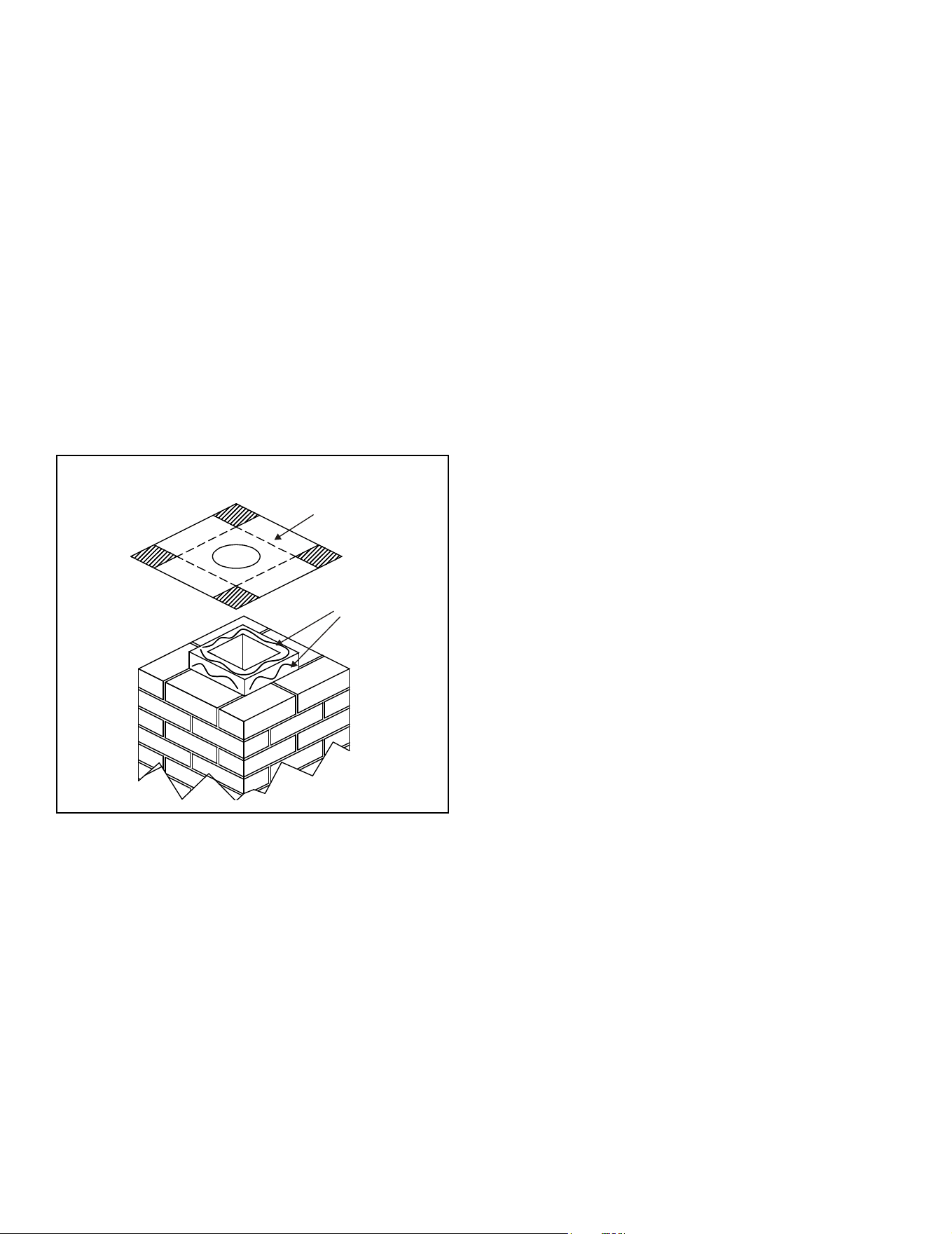
Figure 5.6
CUT AND BEND
FLASHING AS NEEDED
TO FIT CHIMNEY
SEALANT
ADHESIVE
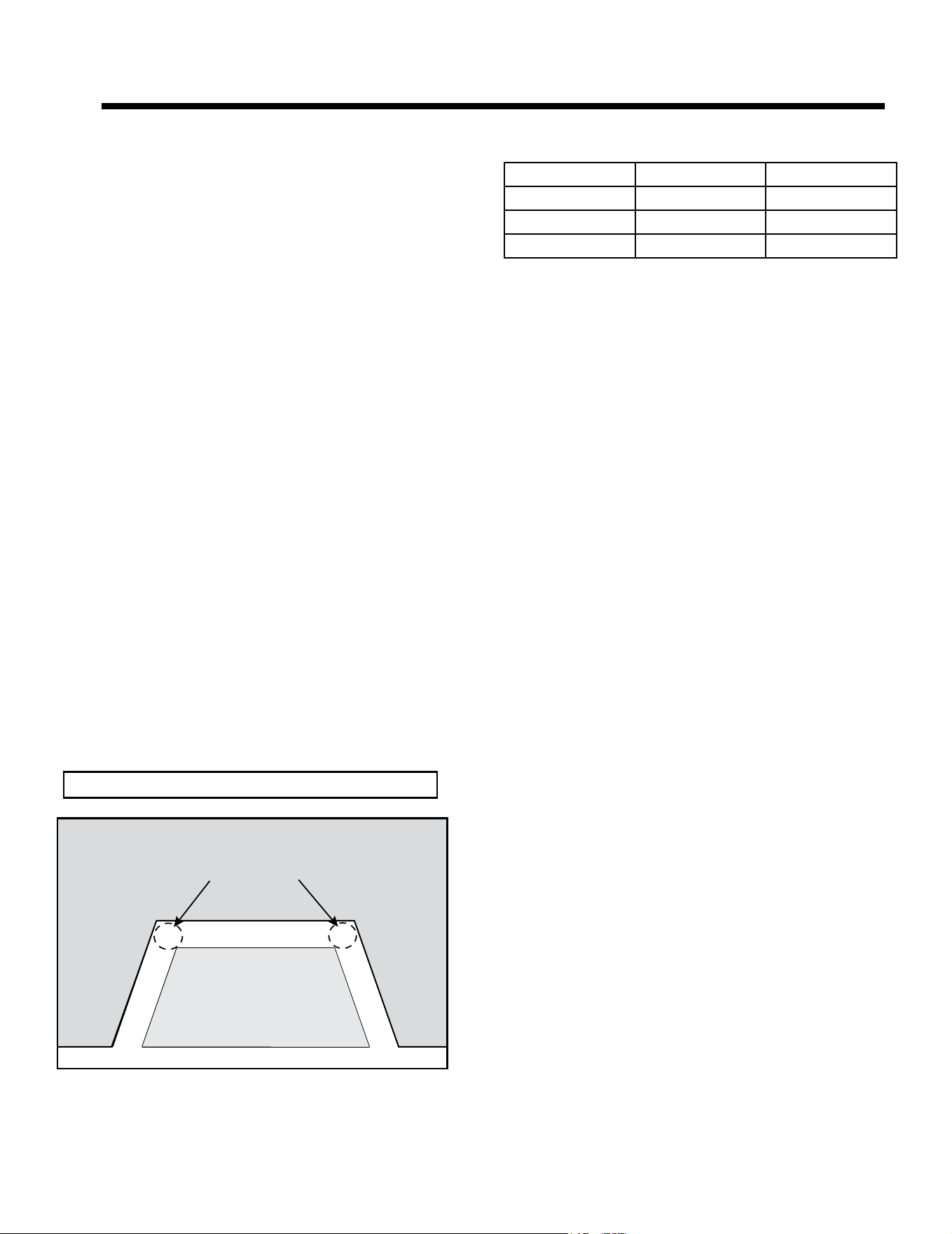
• Trim chimney top plate to minimize excess overhang or
bend over ue tile. See Figure 5.6.
• Place 3/8 inch bead of 300 ºF minimum continuous
exposure rating silicone on ue tile top.
E. Connecting Vent Pipe
Reference instructions in the termination kit.
• Install the 3 in. exible vent pipe(s) down through the
chimney.
• Secure the exhaust exible vent pipe to the exhaust
starting collar on top of the appliance with three screws.
See Figure 5.1.
For best results in cold climate be sure 3 in. ex is ush
and tight to the collar slide plate assembly. Seal with
stove cement or aluminum foil tape. Do not use silicone.
• Use 3 screws to attach the section of inlet air vent to the
inlet air starting collar on the collar slide plate assembly.
See Figure 5.1. NOTE: The collar slide plate assembly
may be removed from appliance to aid installation and
service.
For best results in cold climate be sure 3 in. ex is ush
and tight to the collar slide plate assemby. Seal with
stove cement or aluminum foil tape. Do not use silicone.
27
Majestic • TRILLIANT25IN/IL, TRILLIANT30IN/IL, TRILLIANT35IN/IL Installation Manual • 2571-980 Rev. G • 6/24
WARNING! Risk of Fire! Only an approved Hearth &
Home Technologies surround may be used to cover inte-
gral grills on solid fuel burning replaces. No other com-
ponents such as shrouds, sheetmetal plates, etc., may be
used to seal off vents.
WARNING! Risk of Explosion! Failure to position the
parts in accordance with these diagrams or failure to use
only parts specically approved with this appliance may
result in property damage or personal injury.
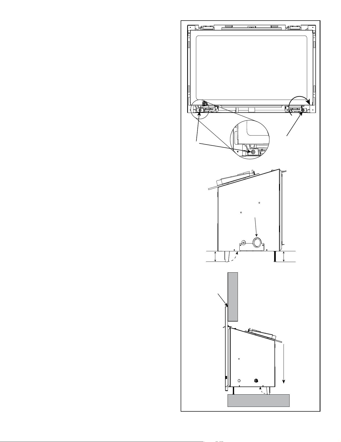
Figure 5.7 Leveling Leg Detail
F. Placing, Securing and Leveling the
Appliance
WARNING! Risk of Explosion/Combustion Fumes!
Connect vent sections per installation instructions.
• Connect exhaust vent pipe ONLY to exhaust starting
collar and termination cap center collar.
• Connect inlet air vent ONLY to inlet air collar on
appliance and either the termination cap inlet air collar
OR terminate within chimney.
• DO NOT allow vent to sag below connection point to
appliance.
• Install insert (without surround attached) into existing
replace while pulling collar slide plate assemby forward.
• Install gas line into hole provided on side. See Figure
5.7.
• Secure collar slide plate assemby to appliance by
securing with #8 screw. See Figure 5.1.
• Level the appliance from side to side and front to back.
Adjust leveling legs to desired vertical position so
appliance is level. Use the leveling bolts included with
the manual bag.
• Position any excess exible vent pipe back up into
chimney without sagging. Twist and push flex vent
together to shorten.
• Attach surround. Follow instructions for surround
installation included with the front.
• Push insert into the opening so that it tightly overlaps
the replace opening.
3/16 in.
ALLEN BOLT
3/16 in.
ALLEN BOLT
RAISE
2 in.
2 in.
GAS LINE
ACCESS
W
A
L
L
FLOOR
REDUCE GAP
ABOVE SURROUND
LOWER REAR
LEVEL LEGS
TO REDUCE
GAP ABOVE
SURROUND
NOTE: Use Allen bolts to
adjust rear level legs.
28
Majestic • TRILLIANT25IN/IL, TRILLIANT30IN/IL, TRILLIANT35IN/IL Installation Manual • 2571-980 Rev. G • 6/24
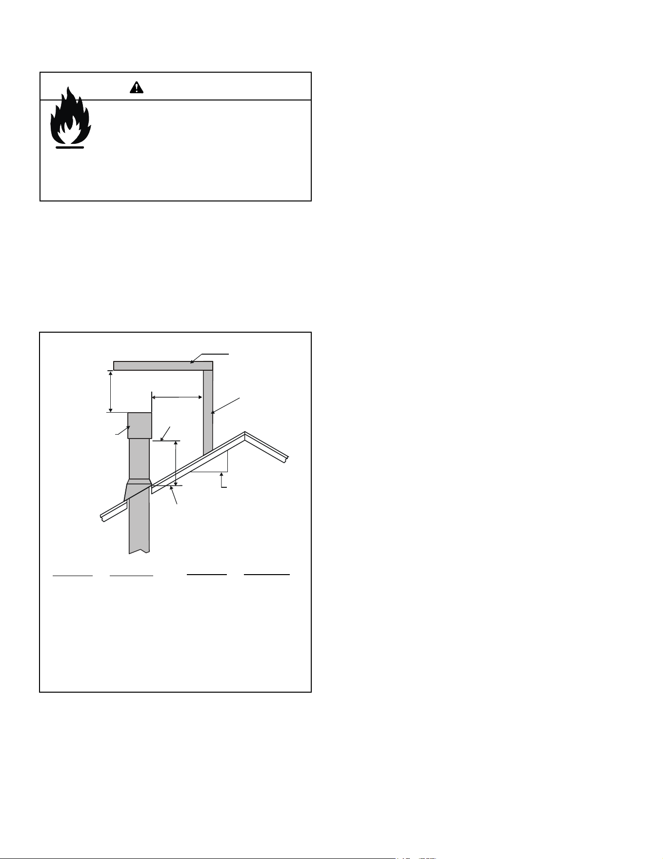
G. Installing Termination Cap
Roof Pitch H (Min.) Ft.
Flat to 6/12....................1.0*
Over 6/12 to 7/12 ........ 1.25*
Over 7/12 to 8/12 .......... 1.5*
Over 8/12 to 9/12 .......... 2.0*
Over 9/12 to 10/12 ........ 2.5*
Over 10/12 to 11/12 ..... 3.25
Figure 5.8 Minimum Height from Roof to Lowest Discharge
Opening
Roof Pitch H (Min.) Ft.
Over 11/12 to 12/12 ....... 4.0
Over 12/12 to 14/12 ....... 5.0
Over 14/12 to 16/12 ....... 6.0
Over 16/12 to 18/12 ....... 7.0
Over 18/12 to 20/12 ....... 7.5
Over 20/12 to 21/12 ....... 8.0
HORIZONTAL
OVERHANG
VERTICAL
WALL
GAS DIRECT VENT
TERMINATION CAP
12
X
ROOF PITCH
IS X/ 12
LOWEST
DISCHARGE
OPENING
2 FT.
MIN.
20 INCHES MIN.
H (MIN.) - MINIMUM HEIGHT FROM ROOF
TO LOWEST DISCHARGE OPENING
* H minimum may vary depending on regional snowfall.
Refer to local codes.
CAUTION! Risk of Cuts/Abrasions/Flying Debris.
Wear protective gloves and safety glasses during instal-
lation. Sheet metal edges are sharp.
For installation of termination cap see minimum vent
heights for various pitched roofs. See Figure 5.8.
Fire Risk.
Maintain vent clearance to combustibles as
specied.
• DO NOT pack air space with insulation or other
materials.
Failure to keep insulation or other materials away
from vent pipe may cause overheating and re.
WARNING
29
Majestic • TRILLIANT25IN/IL, TRILLIANT30IN/IL, TRILLIANT35IN/IL Installation Manual • 2571-980 Rev. G • 6/24
A. General Information
WARNING! Risk of Shock or Explosion! DO NOT wire
110-120 VAC to the valve or to the appliance wall switch.
Incorrect wiring will damage controls.
NOTICE: This appliance must be electrically wired
and grounded in accordance with local codes or, in the
absence of local codes, with National Electric Code
ANSI/NFPA 70-latest edition or the Canadian Electric
Code CSA C22.1.
• This appliance comes with a 110-120 VAC cord
assembly. This is required for proper operation of the
appliance (IntelliFire Touch
®
Ignition). An outlet box may
be installed in a bottom back corner of the existing solid
fuel masonry or factory built replace to plug in the cord
assembly, or the supplied power cord may be routed out
onto the hearth to a nearby outlet.
• A 110-120 VAC circuit for this product must be protected
with ground-fault circuit-interrupter protection, in
compliance with the applicable electrical codes, when
it is installed in locations such as in bathrooms or near
sinks.
• Low voltage and 110-120 VAC voltage cannot be shared
within the same wall box.
• In some instances, the spark ignition of the replace may
cause intermittent, non-damaging, interference during
the lighting sequence with a TV plugged into the same
circuit. It is recommended that the replace and TV use
different circuits to mitigate the interference potential.
If interference is occurring on the same circuit, the use
of surge protectors may help alleviate the interference.
6 6
Electrical Information
Electrical Service and Repair
WARNING! Risk of Shock! Label all wires prior to dis-
connection when servicing controls. Wiring errors can
cause improper and dangerous operation. Verify proper
operation after servicing.
WARNING! Risk of Shock! Replace damaged wire with
type 105 ºC rated wire. Wire must have high temperature
insulation.
• Refer to Service Parts section of appliance Owner’s
Manual for replacement part information.
NOTICE: DO NOT wire 110-120 VAC to wall switch.
Figure 6.1 Electrical Outlet Detail
ELECTRICAL OUTLET LOCATIONS
MASONRY
MASONRY
APPLIANCE
RECOMMENDED
Reset Switch
• A reset switch and USB-C battery plug are included
with the appliance surround and should be attached to
the side of the surround. See Installation instructions
shipped with the appliance front.
• Reset switch must be installed and in the “ON” position
for appliance to operate.
Appliance Size Left Side Right Side
25 in. 10 ft. 6 in. 8 ft.
30 in. 10 ft. 3 in. 7 ft. 6 in.
35 in. 10 ft. 7 ft.
Appliance Cord Length (approximate)
30
Majestic • TRILLIANT25IN/IL, TRILLIANT30IN/IL, TRILLIANT35IN/IL Installation Manual • 2571-980 Rev. G • 6/24
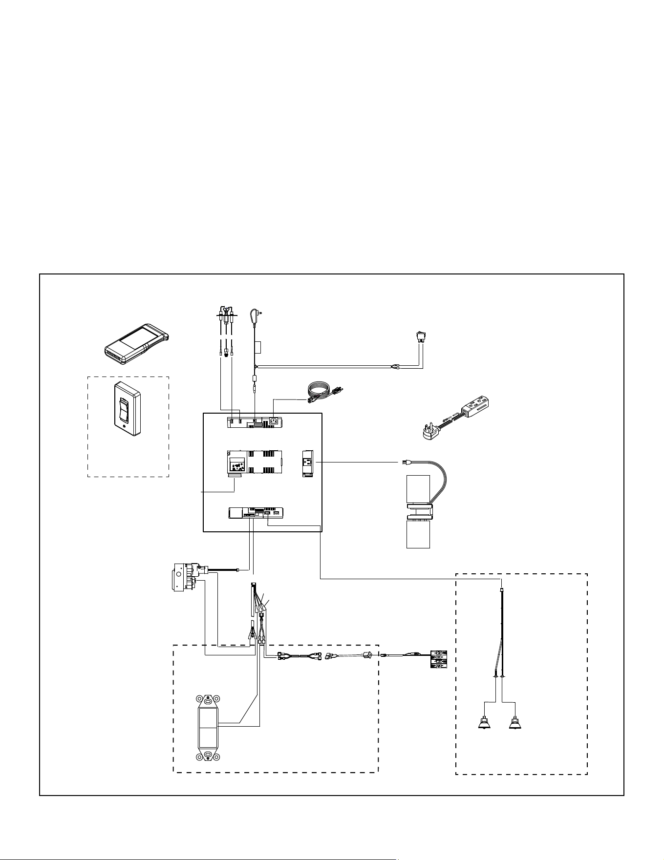
Figure 6.2 IntelliFire Touch Wiring Diagram
FLAME
SENSE
IGNITER
TO POWER
CORD
110-120 VAC
FAN 110-120 VAC
RF MODULE
I
S
6 PIN
BATTERY PACK
BRN
ORANGE
(PILOT)
GREEN
(MAIN)
IFT-RC400
REMOTE
CONTROL
IFT-RC150
WIRELESS
WALL SWITCH
(OPTIONAL)
APPLIANCE
ON/OFF
CONTROL
BRN
BLK
BLK
RED
BLK
(OPTIONAL)
(OPTIONAL)
ORANGE
WHITE
BACK VIEW
TOP VIEW
FRONT VIEW
SIDE
VIEW
POWER CORD
* JUMPER WIRE AVAILABLE FROM YOUR LOCAL DEALER
2550-013 (NG)
2550-014 (LP)
2326-152
2326-130
2326-150
2326-120
2166-302 (NG)
2166-303 (LP)
GFK-160A
2326-142
SRV2326-222
WSK-21-W
2201-024
SRV2531-140
LIGHT WIRE
ASSEMBLY
2532-017
2201-150
HALOGEN BULBS (X 2)
NOT AN OPTION WITH 25 in. MODELS
* MODULE RESET SWITCH
(LOCATED ON SURROUND)
* Reset switch must be installed
and in the “ON” position for
appliance to operate.
TO POWER CORD 110-120 VAC
2206-299
2326-191
RED
JUMPER WIRE *
SRV2187-198
40 IN. WIRE HARNESS
B. Wiring Requirements
IntelliFire Touch
®
Ignition System Wiring
WARNING! Risk of Shock or Explosion! DO NOT wire
IPI controlled appliance power cord to a switched circuit.
Incorrect wiring will override IPI safety lockout.
• Refer to Figure 6.2, IntelliFire Touch (IPI) Wiring Diagram.
• This appliance is equipped with an IntelliFire control valve
which operates on a 6 volt system.
• Ensure the 6 volt transformer is plugged into the supplied
cord assembly to supply power to the unit OR install 4 AA
cell batteries (not included) into the battery pack before
use.
• Reset switch must be installed and in the “ON” position
for appliance to operate.
31
Majestic • TRILLIANT25IN/IL, TRILLIANT30IN/IL, TRILLIANT35IN/IL Installation Manual • 2571-980 Rev. G • 6/24
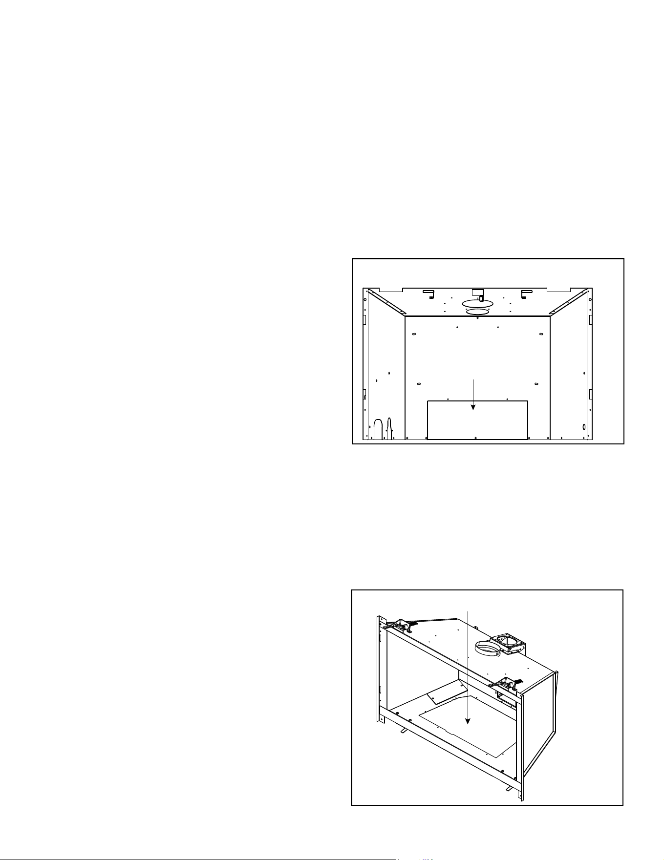
On units already installed, removal of decorative barrier
front and gas insert may be required.
Option 1:
• Detach exible liner from top of unit if insert is installed by
removing the collar slide plate screw. See Figure 5.1.
• Remove the ve screws on the rear cover plate. See
Figure 6.3.
• Service / replace fan. Figure 6.2 shows a wiring dia-
gram.
• Reinstall the rear cover plate back on the unit.
• Reattach exible liner and replace collar slide plate
screw. See Figure 5.1.
Figure 6.3 Cover Plate Removed (Option 1)
INSTALL FAN
OPTION 1
OPTION 2
Figure 6.4 Through Valve Plate Opening (Option 2)
INSTALL FAN
Option 2:
• Remove appliance front, glass, logs, base pan assem-
bly, burner assembly and valve plate assembly. See
Figure 6.4.
• Service / install fan. Figure 6.2 shows a wiring diagram.
• Reinstall valve plate assembly, burner assembly, base
pan assembly, logs and appliance glass and front.
C. Installation / Service for Fan
REAR COVER PLATE
NOTICE: Batteries should only be used as a power source
in the event of an emergency power outage. Batteries
should not be used as a primary long-term power source.
Battery polarity must be correct when installing batteries.
DO not store batteries in the battery pack when the
appliance is powered by the 6 volt transformer connected
to permanent electrical service. Store battery pack in
apppliance manual bag when not in use.
Battery Pack
Battery pack is not factory installed in appliances. See
appliance manual bag for battery pack. Battery pack
may be installed without batteries during normal opera-
tion.
When operating appliance under battery power, battery
pack MUST be moved outside of the appliance.
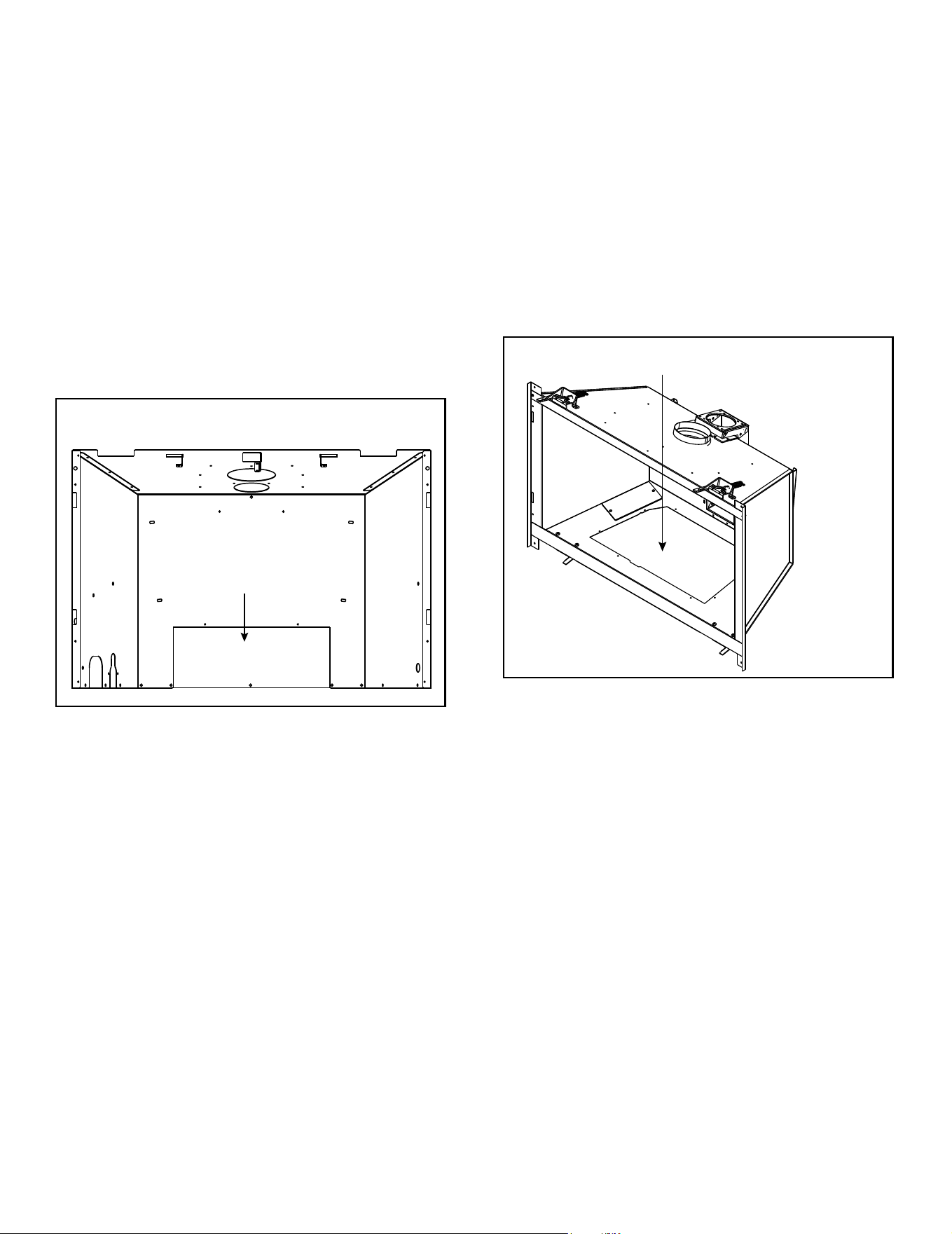
32
Majestic • TRILLIANT25IN/IL, TRILLIANT30IN/IL, TRILLIANT35IN/IL Installation Manual • 2571-980 Rev. G • 6/24
Option 2:
• Remove appliance front, glass, logs, base pan assem-
bly, burner assembly and valve plate assembly. See
Figure 6.6.
• Service / replace halogens. Figure 6.2 shows a wiring
diagram.
• Reinstall valve plate assembly, burner assembly, base
pan assembly, logs and appliance glass and front.
Figure 6.5 Cover Plate Removal (Option 1)
INSTALL HALOGENS
OPTION 1
OPTION 2
Figure 6.6 Through Valve Plate Opening (Option 2)
INSTALL HALOGENS
D. Installation / Service for Halogens
On units already installed, removal of decorative barrier
front and gas insert may be required.
Option 1:
• Detach exible liner from top of unit if insert is installed by
removing the collar slide plate screw. See Figure 5.1.
• Remove the ve screws on the rear cover plate. See
Figure 6.5.
• Service / replace halogens. Figure 6.2 shows a wiring
diagram.
• Reinstall the rear cover plate back on the unit.
• Reattach exible liner and replace collar slide plate
screw. See Figure 5.1.
REAR COVER PLATE
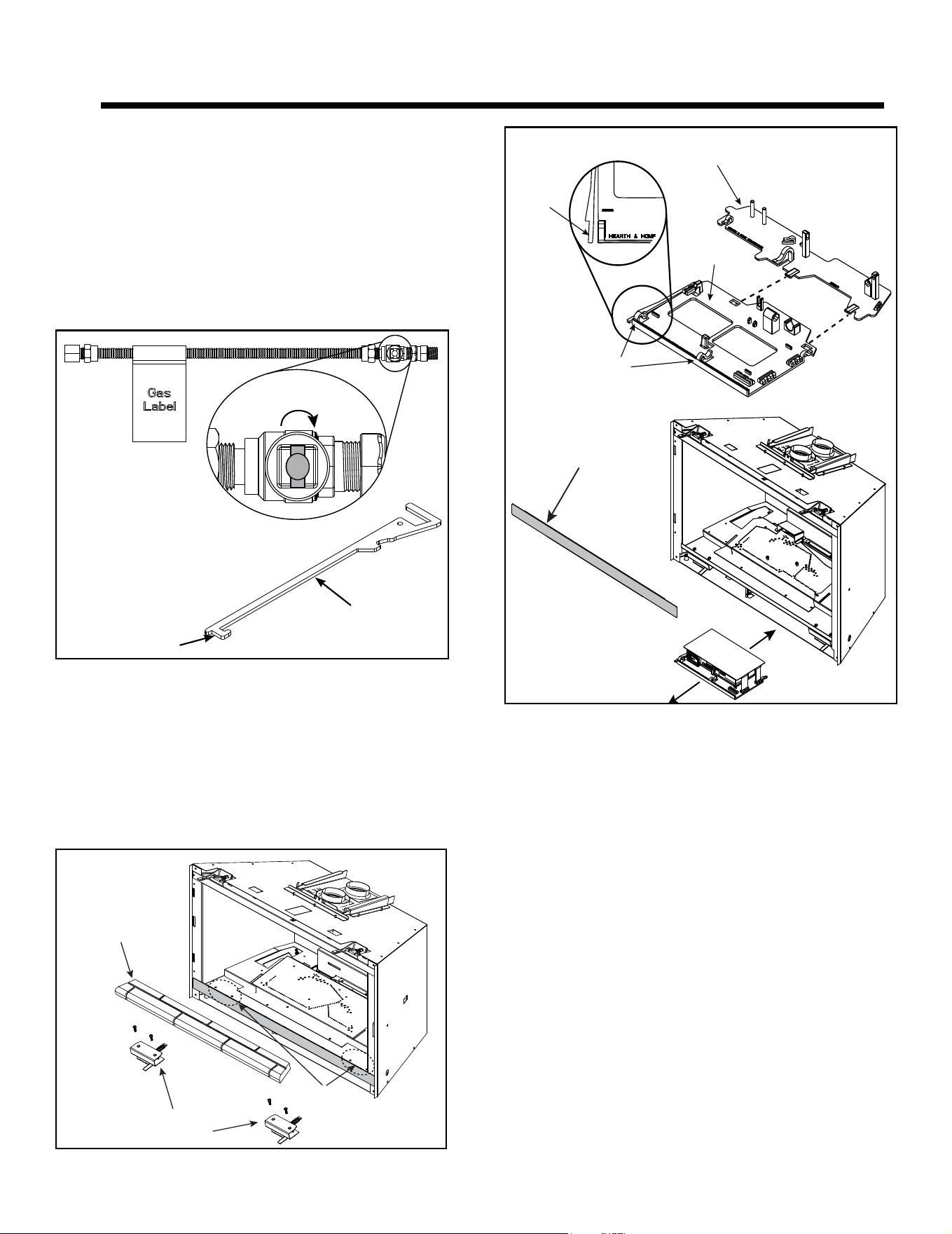
33
Majestic • TRILLIANT25IN/IL, TRILLIANT30IN/IL, TRILLIANT35IN/IL Installation Manual • 2571-980 Rev. G • 6/24
A. Fuel Conversion
• Make sure the appliance is compatible with available gas
types.
• Conversions must be made by a qualified service
technician using Hearth & Home Technologies specied
and approved parts.
• Reference the following diagrams for gas shut off detail
and component access.
• Reference Section 9.A to remove xed glass assembly.
7 7
Gas Information
Figure 7.2 Glass Clip Assembly Removal
BASE REFRACTORY
GLASS CLIP
ASSEMBLIES
GLASS
CLIP ASSEMBY
SCREW ACCESS
Figure 7.1 Gas Shut-off
Figure 7.3 Component Tray
• Glass clip assemblies can be removed for additional
component accessibility.
• Use multi-purpose tool to assist with gas shutoff. See
Figure 7.1. The gas ball valve is in the “OFF” position
from manufacturer.
WARNING! Glass seal plate must be properly installed.
Risk of elevated component temps and carbon monoxide
exposure.
NOTE: Bottom right glass clip on 25 inch models must
be removed to gain access to controls.
OFF POSITION
(TURN KNOB CLOCKWISE)
NOTE: Use the Multi-Purpose
Tool to assist with gas shut-off.
MULTI-PURPOSE TOOL
GAS SHUT OFF
GLASS SEAL PLATE
PRESS
TAB TO
RELEASE
UNCLIP
WIRES
COMPONENT
TRAY
COMPONENT
TRAY RECEIVER
NOTE: The gas ball
valve is in the “OFF
position from
manufacturer.
CAUTION: Be sure to reinstall the component heat shield
before ring the appliance. Components will overheat
without heat shield.
CAUTION: Any wires removed from the wire clips during
appliance installation or service must be re-installed in the
wire clips.
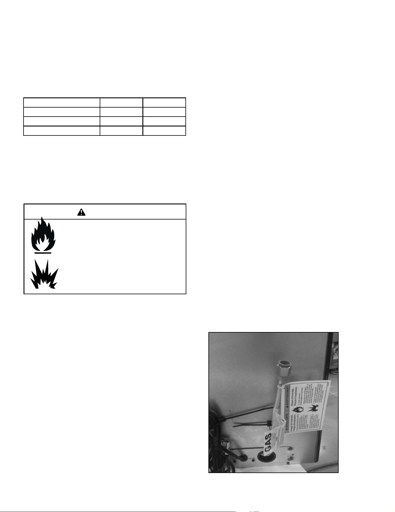
34
Majestic • TRILLIANT25IN/IL, TRILLIANT30IN/IL, TRILLIANT35IN/IL Installation Manual • 2571-980 Rev. G • 6/24
WARNING! Risk of Fire or Explosion! High pressure
will damage valve. Low pressure may cause explosion.
• Verify inlet pressures. Verify minimum pressures when
other household gas appliances are operating.
• Install regulator upstream of valve if line pressure is
greater than 1/2 psig.
Gas Pressure Natural Gas Propane
Minimum inlet pressure 5.0 in. w.c. 11.0 in. w.c.
Maximum inlet pressure 10.0 in. w.c. 13.0 in. w.c.
Manifold pressure 3.5 in. w.c. 10.0 in. w.c.
Note: Have the gas supply line installed in accordance with
local codes, if any. If not, follow ANSI Z223.1. Installation
should be done by a qualied installer approved and/or
licensed as required by the locality. (In the Commonwealth
of Massachusetts installation must be performed by a
licensed plumber or gas tter).
Note: A listed (and Commonwealth of Massachusetts ap-
proved) 1/2 in. (13 mm) T-handle manual shut-off valve
and exible gas connector are connected to the 1/2 in. (13
mm) control valve inlet.
• If substituting for these components, please consult
local codes for compliance.
Fire Risk.
Explosion Hazard.
High pressure will damage valve.
• Disconnect gas supply piping BEFORE
pressure testing gas line at test pressures
above 1/2 psig.
• Close the manual shutoff valve BEFORE
pressure testing gas line at test pressures
equal to or less than 1/2 psig.
WARNING
B. Gas Pressure
• Optimum appliance performance requires proper input
pressures.
• Gas line sizing requirements will be determined in ANSI
Z223.1 National Fuel Gas Code in the USA and CAN/
CGA B149 in Canada.
• Pressure requirements are:
C. Gas Connection
• Refer to Reference Section 3 for location of gas line
access in appliance.
• The gap between supply piping and gas access hole
may be caulked with caulk with a minimum of 300
ºF continuous exposure rating or stuffed with non-
combustible, unfaced insulation to prevent cold air
inltration.
• Ensure that gas line does not come in contact with outer
wrap of the appliance. Follow local codes.
• Pipe incoming gas line to the factory supplied ex line.
See Figure 7.4.
• Connect incoming gas line to the 1/2 in. (13 mm)
connection on manual shutoff valve.
WARNING! Risk of Fire or Explosion! Support control
when attaching pipe to prevent bending gas line.
• A small amount of air will be in the gas supply lines.
WARNING! Risk of Fire or Explosion! Gas build-up dur-
ing line purge could ignite.
• Purge should be performed by qualified service
technician.
• Ensure adequate ventilation.
• Ensure there are no ignition sources such as sparks
or open ames.
Light the appliance. It will take a short time for air to purge
from lines. When purging is complete the appliance will
light and operate normally.
WARNING! Risk of Fire, Explosion or Asphyxiation!
Check all ttings and connections with a non-corrosive
commercially available leak-check solution. DO NOT use
open ame. Fittings and connections could have loos-
ened during shipping and handling.
WARNING! Risk of Fire! DO NOT change valve settings.
This valve has been preset at the factory.
Figure 7.4
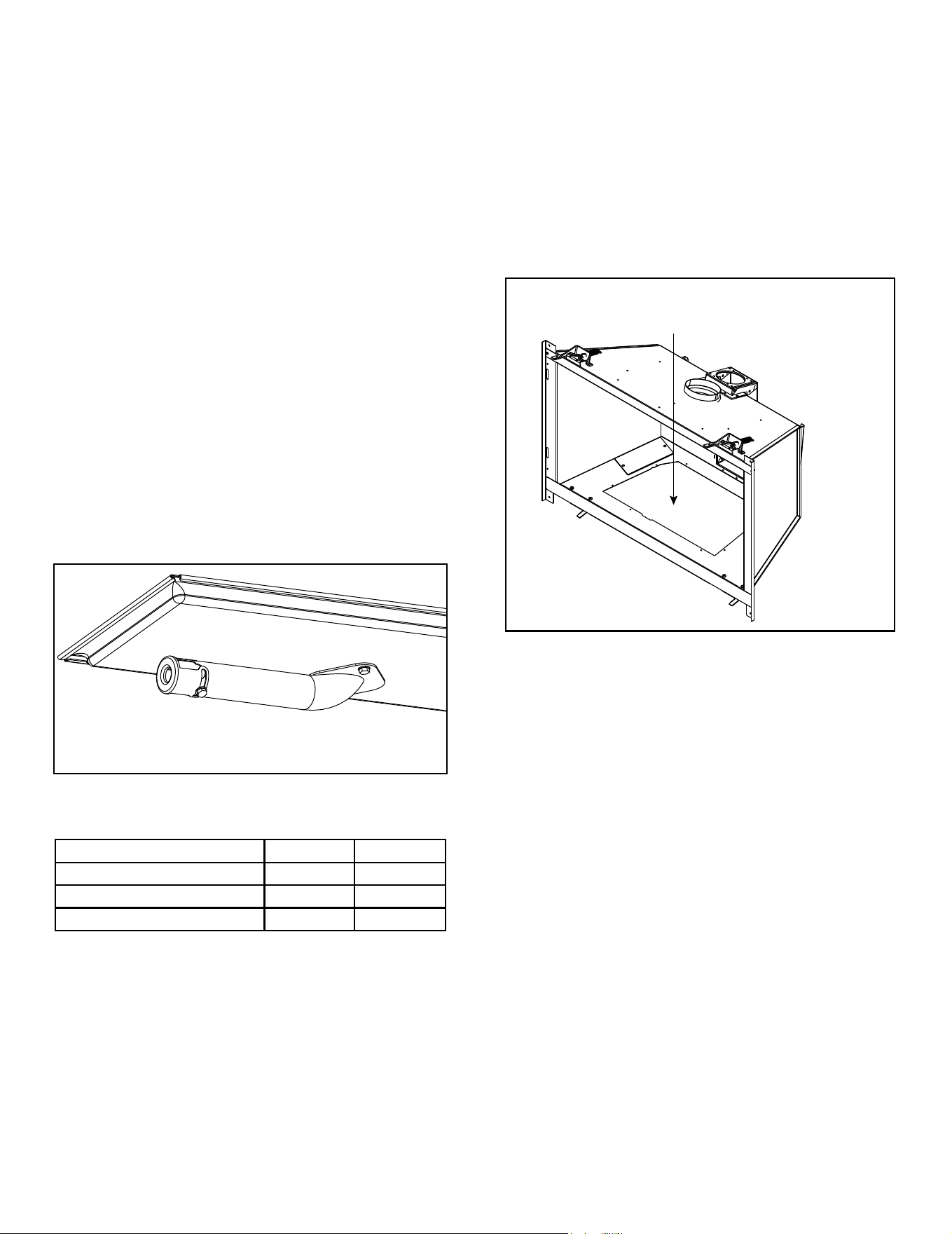
35
Majestic • TRILLIANT25IN/IL, TRILLIANT30IN/IL, TRILLIANT35IN/IL Installation Manual • 2571-980 Rev. G • 6/24
D. High Altitude Installations
NOTICE: If the heating value of the gas has been reduced,
these rules do not apply. Check with your local gas utility
or authorities having jurisdiction.
When installing above 2000 feet elevation:
• In the USA: Reduce input rate 4% for each 1000 feet
above 2000 feet.
• In CANADA: Input ratings are certied without a reduction
of input rate for elevations up to 4500 feet (1370 m)
above sea level. Please consult provincial and/or
local authorities having jurisdiction for installations at
elevations above 4500 feet (1370 m)
Check with your local gas utility to determine proper
orice size.
E. Air Shutter Setting
Air shutter settings should be adjusted by a qualied ser-
vice technician at the time of installation. The air shutter
is set at the factory for minimum vertical vent run. Adjust-
ing air shutter may be desired for longer vent runs. See
Figure 7.5.
NOTICE: If sooting occurs, provide more air by opening
the air shutter.
Figure 7.5 Air Shutter
Air Shutter Settings
NG Propane
TRILLIANT25I 3/16 in. 3/8 in.
TRILLIANT30I 3/8 in. Full Open
TRILLIANT35I 3/8 in. 1/2 in.
F. Service / Replace Appliance Gas Valve
• See Figure 7.6.
• Remove appliance front, glass, logs, base pan assem-
bly, burner assembly and valve plate assembly. See
Figure 7.6.
• Service/Replace gas valve.
• Reinstall valve plate assembly, burner assembly, base
pan assembly, logs and appliance glass and front.
Figure 7.6 Gas Valve Detail
SERVICE / REPLACE
APPLIANCE GAS VALVE
36
Majestic • TRILLIANT25IN/IL, TRILLIANT30IN/IL, TRILLIANT35IN/IL Installation Manual • 2571-980 Rev. G • 6/24
8 8
Finishing
A. Mantel, Wall Projections & Hearth
Extensions
WARNING! Risk of Fire! Comply with all minimum clear-
ances to combustibles as specied. Framing or nishing
material closer than the minimums listed must be construct-
ed entirely of noncombustible materials (i.e., steel studs,
concrete board, etc).
Clearance to combustible material under the insert is 1/4
inch (6 mm).
• Use leveling legs to raise insert minimum 1/4 inch (6
mm) above combustible material or outer wrap of factory
built rebox.
Combustible facings must not extend behind the insert
surround. For non-combustible material specications
refer to Section 1.E and 1.F.
Mantels or Wall Projections - Non-Combustible
Mantel Legs or Wall Projections
Figure 8.1 Clearances to Mantel Legs or Wall Projections
(Acceptable on both sides of surround opening)
INTERIOR WALL
TOP VIEW
MANTEL LEG OR WALL PROJECTIONS
SURROUND OPENING
∞
18 in.
12 in.
12 in.
1/4 in. GAP
6 in.
6 in.
Non-Combustible
Combustible
INTERIOR WALL
TOP VIEW
MANTEL LEG OR
WALL PROJECTIONS
SURROUND OPENING
∞
18 in.
1/4 in. Gap
12 in.
A
6 in.
12 in.
*
C
L
*SEE TABLE
1 or 2
Figure 8.2 Minimum Vertical and Maximum Horizontal
Dimensions- Non-Combustible
1/4 in. gap
SURROUND
OPENING
6 in.
12 in.
12 in.
*B
*SEE TABLE
1 or 2
Note: Measurement is taken from top of the surround
opening.
Unit Size
Surround
Model
A B
25 in.
MI25-3523 17-15/16 in. 6-1/16 in.
MI25-3726 18-15/16 in. 9-1/16 in.
MI25-3928 19-15/16 in. 11-1/16 in.
30 in.
MI30-4027 20-7/16 in. 6-9/16 in.
MI30-4230 21-7/16 in. 9-9/16 in.
MI30-4432 22-7/16 in. 11-9/16 in.
35 in.
MI35-4229 21-7/16 in. 5-1/16 in.
MI35-4432 22-7/16 in. 8-1/16 in.
MI35-4832 24-7/16 in. 8-1/16 in.
Table 1 Mantel Leg or Wall Projection Minimum Dimension
needed when Installing a Standard Surround
Note: All numbers in Tables 1 and 2 include the 1/4 in. gap on
surround edge.
Table 2 Mantel Leg or Wall Projection Minimum Dimension
needed when Installing a Custom Surround. Front Model
Determines the Minimum Size of the Custom Surround
Unit
Size
Front Model A B
25 in.
INFIT 14-5/8 in. 1-1/4 in.
FA-TRI, TA-TRI,
MFV-TRI, CSFI25
16-1/16 in. 2-1/2 in
30 in.
INFIT 17-1/8 in. 1-1/4 in.
FA-TRI, TA-TRI,
MFV-TRI, CSFI30
18-9/16 in. 2-1/2 in
35 in.
INFIT 19-3/4 in. 1-1/4 in.
FA-TRI, TA-TRI,
MFV-TRI, CSFI35
21-1/16 in. 2-1/2 in
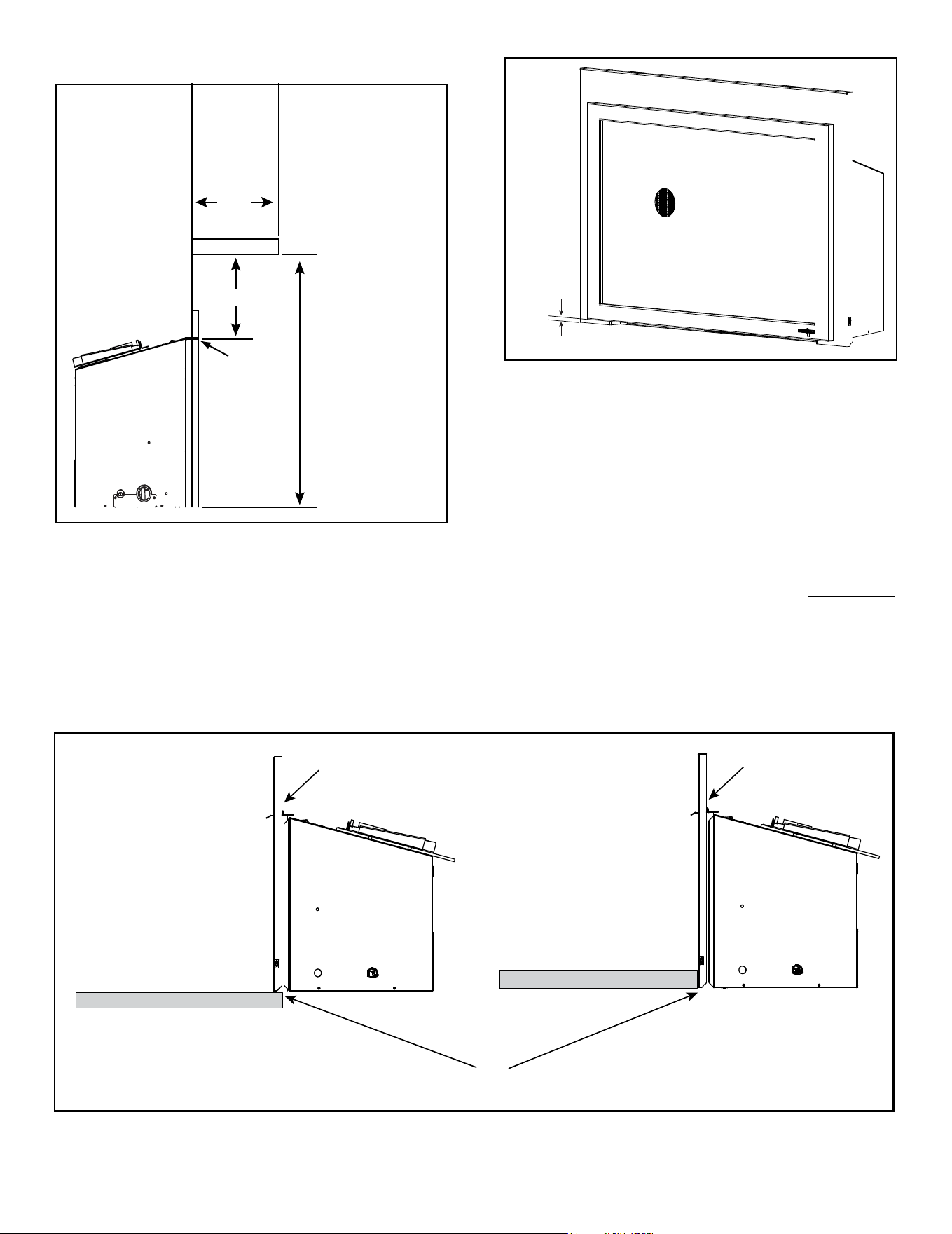
37
Majestic • TRILLIANT25IN/IL, TRILLIANT30IN/IL, TRILLIANT35IN/IL Installation Manual • 2571-980 Rev. G • 6/24
B. Hearth Extension
1/2 in.
Figure 8.4 Minimum Required 1/2 in. Gap
Mantels - Combustible
Figure 8.3 Minimum Vertical and Maximum Horizontal
Dimensions - Combustible
Measurement to bottom
of appliance:
= 29-1/4 in. (25")
= 32-3/4 IN. (30")
= 36-1/4 IN. (35")
Measurement
from surround
opening.
12 in.
12 in.
SURROUND
Flooring & Hearth Material
SURROUND
YES
NO
Flooring & Hearth Material
Flooring & hearth material must remain below the bottom of surround
Figure 8.5 Flooring & Hearth Material
• All ooring and hearth material must remain below the
bottom of the surround. See Figure 8.5.
• Combustible ooring may be located in front of the
appliance. Exception - no vinyl / adhesive ooring. See
Figure 8.6.
• 1/2 inch gap under the bottom of the front must be
maintained. See Figure 8.4.
• A minimum 1/4 inch gap from the bottom of the appliance
to the metal oor of the solid fuel rebox is REQUIRED.
See side view in Figure 8.7.
• Combustible flooring underneath the appliance is
acceptable with a 1/4 inch gap. See Figure 8.7.
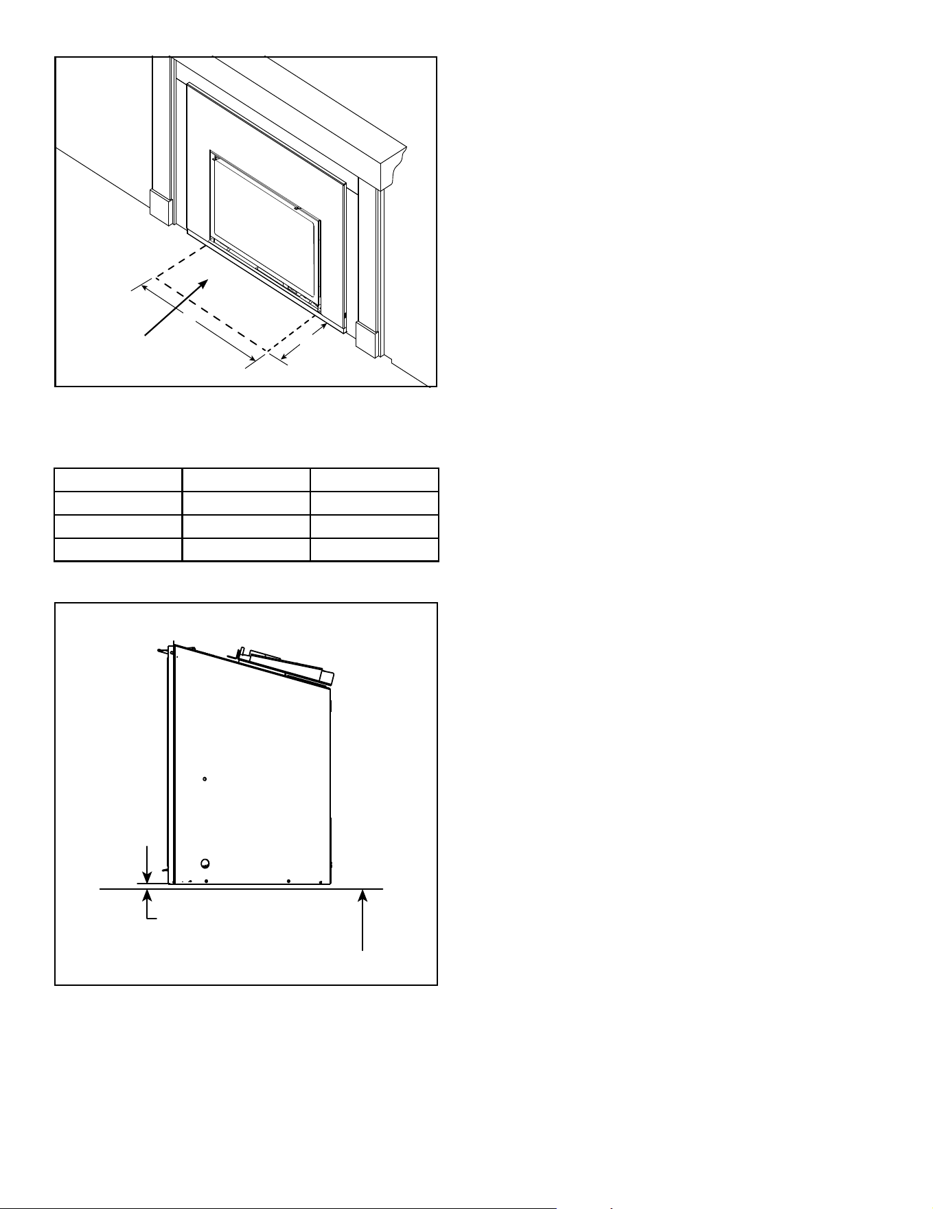
38
Majestic • TRILLIANT25IN/IL, TRILLIANT30IN/IL, TRILLIANT35IN/IL Installation Manual • 2571-980 Rev. G • 6/24
Y
X
Figure 8.6 Hearth - Combustible Material Exception
NO VINYL /
ADHESIVE FLOORING
Figure 8.7 Solid Fuel Floor Clearance
SIDE VIEW
MINIMUM 1/4 IN. REQUIRED
COMBUSTIBLE FLOOR UNDERNEATH APPLIANCE
Appliance Size Depth (X) Width (Y)
25 in. 16 in 25-3/4 in.
30 in. 16 in 30-3/4 in.
35 in. 16 in 35-3/4 in.
Vinyl / Adhesive Flooring - Minimums
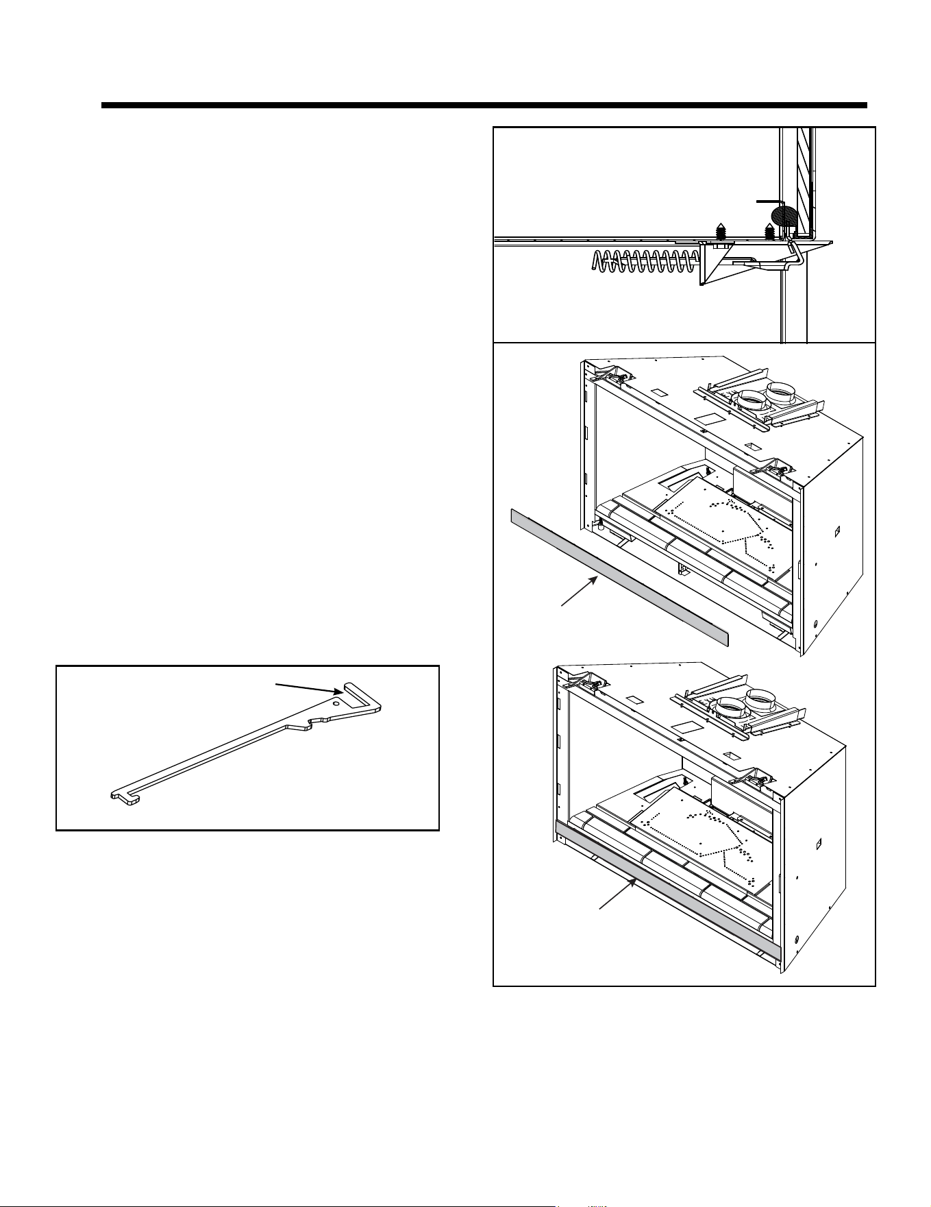
39
Majestic • TRILLIANT25IN/IL, TRILLIANT30IN/IL, TRILLIANT35IN/IL Installation Manual • 2571-980 Rev. G • 6/24
9 9
Appliance Setup
A. Fixed Glass Assembly
WARNING! Risk of Asphyxiation! Handle xed glass
assembly with care. Inspect the gasket to ensure it is
undamaged and inspect the glass for cracks, chips or
scratches.
• DO NOT strike, slam or scratch glass.
• DO NOT operate replace with glass removed, cracked,
broken or scratched.
• Replace as a complete assembly.
Removing Fixed Glass Assembly
CAUTION! Handle xed glass assembly with care.
Glass is breakable.
• Avoid striking, scratching or slamming glass
• Avoid abrasive cleaners
• DO NOT clean glass while it is hot
• The glass assembly fastens to the replace in four
places. Four of the fastening mechanisms are spring-
loaded glass latches. An example of the glass latch is
shown in Figure 9.2.
• To release glass assembly, use the supplied multi-
purpose tool (Figure 9.1) to pull the two bottom spring-
loaded latches forward and allow them to retract away
from the glass assembly. Tilt the bottom of the glass
assembly outward until the top latches disengage.
Replacing Fixed Glass Assembly
• Tilt the top of the glass assembly toward replace and
slide glass assembly upward to engage
top latches. Verify top latches are fully engaged and
then fasten the two bottom latches using the supplied
multi-purpose tool.
• Reinstall door or decorative barrier front.
Figure 9.2 Glass Seal Plate
GLASS SEAL PLATE
GLASS SEAL
PLATE INSTALLED
Figure 9.1 Multi-PurposeTool
GLASS CLIPS
WARNING! Glass seal plate must be properly installed.
Risk of elevated component temps and carbon monoxide
exposure.
Note: Appliance is shipped with glass seal plate in the
installed position.
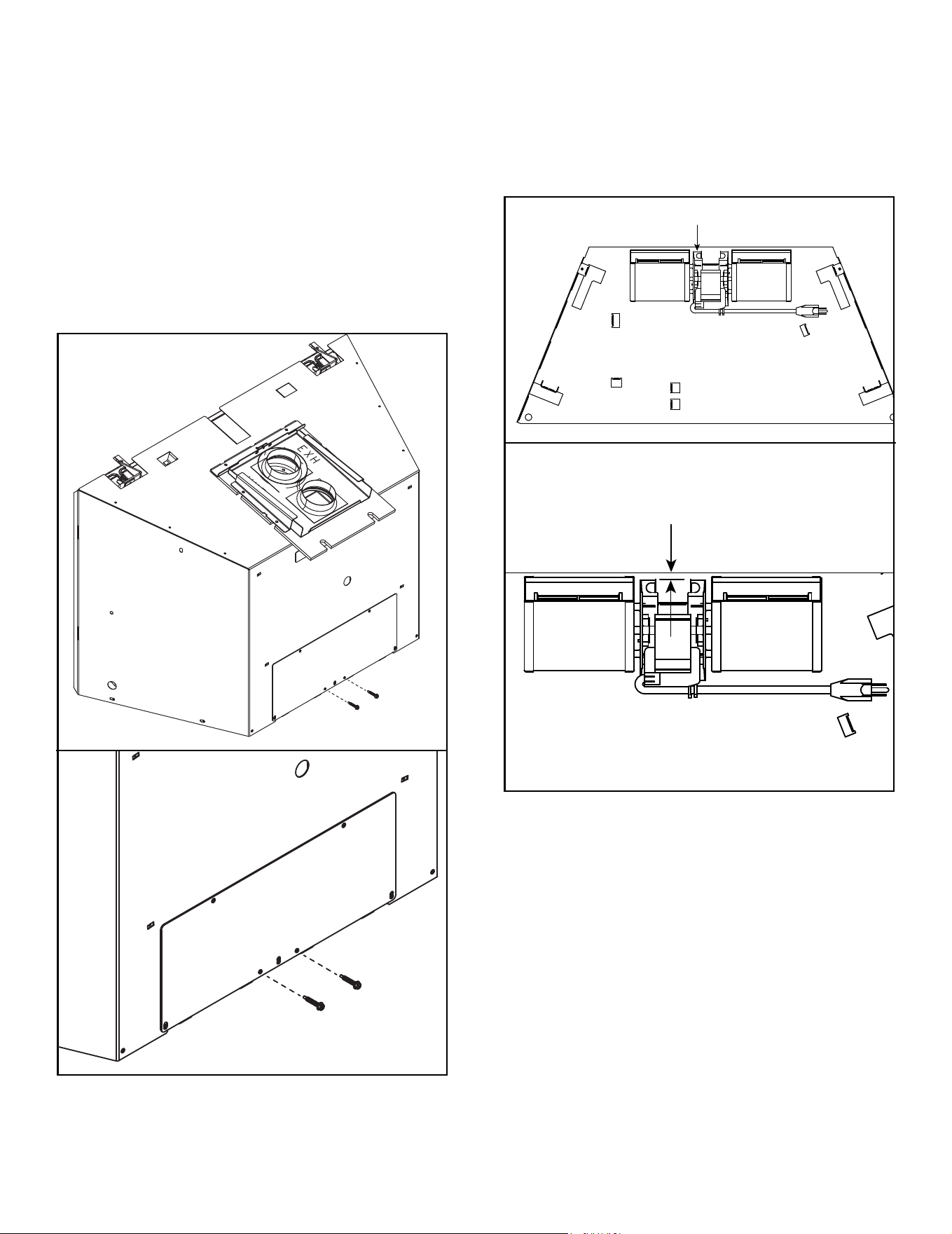
40
Majestic • TRILLIANT25IN/IL, TRILLIANT30IN/IL, TRILLIANT35IN/IL Installation Manual • 2571-980 Rev. G • 6/24
B. Remove the Shipping Materials
Remove shipping materials from inside or underneath
the rebox.
Note: Remove the zip ties from the appliance that hold
the electrical cord, gas exline and multi-purpose tool in
place for shipping.
C. Clean the Appliance
Clean/vacuum any sawdust that may have accumulated
inside the rebox or underneath in the control cavity.
D. Accessories
Install approved accessories per instructions included
with accessories. Contact your dealer for a list of ap-
proved accessories.
WARNING! Risk of Fire and Electric Shock! Use ONLY
Hearth & Home Technologies-approved optional acces-
sories with this appliance. Using non-listed accessories
could result in a safety hazard and will void the warranty.
Figure 9.4 Fan Location
Figure 9.3 Remove Shipping Screws
FAN
BACK COVER PLATE
Remove Shipping Screws
NOTICE: Remove shipping screws to reduce the noise
created from fan vibration.
1. Remove the two shipping screws from the back cover
plate as illustrated in Figure 9.3, Detail A.
2. When servicing or replacing a fan, note the location
of the fan and fan dampener as shown in Figure 9.4.
The fan dampener will be located under the fan. The
gap between the back of the outer wrap and the fan
should be between 1/16 inch and 1/8 inch as shown
in Figure 9.4, Detail B. Additionally, the fan should not
touch the rebox.
BACK COVER PLATE
GAP = 1/16 IN. TO 1/8 IN.
DETAIL B
DETAIL A
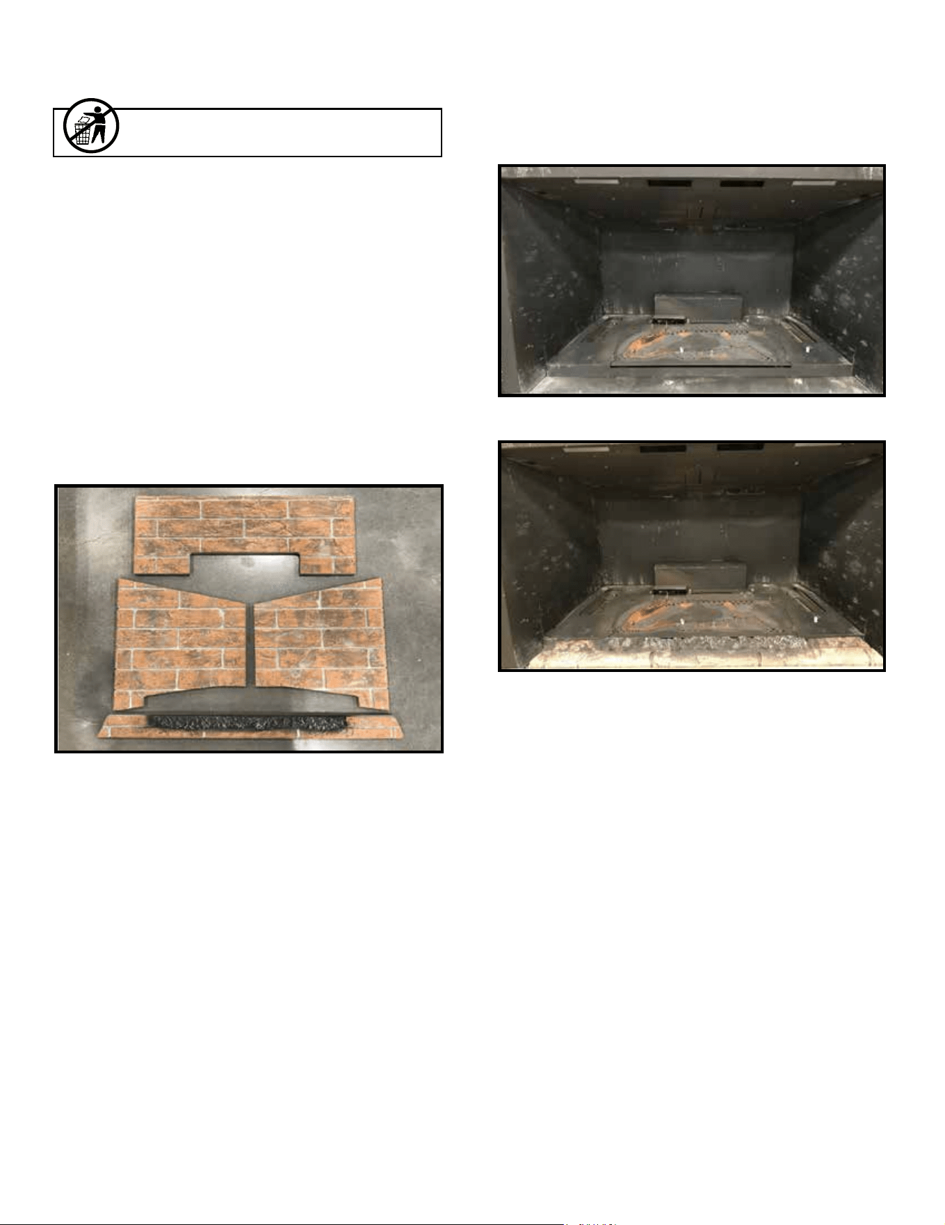
41
Majestic • TRILLIANT25IN/IL, TRILLIANT30IN/IL, TRILLIANT35IN/IL Installation Manual • 2571-980 Rev. G • 6/24
E. Refractory
CAUTION! Risk of Cuts or Abrasions. Wear protective
gloves and safety glasses during installation.
NOTICE: Handle refractory panels with care. Refractory
may chip or crack if dropped or impacted.
KIT COMPONENTS (Refractory shown in Figure 1)
(1) Left Refractory
(1) Right Refractory
(1) Back Refractory
(1) Base Refractory
Leave this manual with party responsible for use
and operation.
Figure 2 Empty Firebox
Figure 1 Refractory Kit Components
INSTALLATION
1. Install base refractory. See Figure 3.
Figure 3 Base Refractory Installed
Service Parts:
If replacement panels are needed, the entire kit must be
ordered.
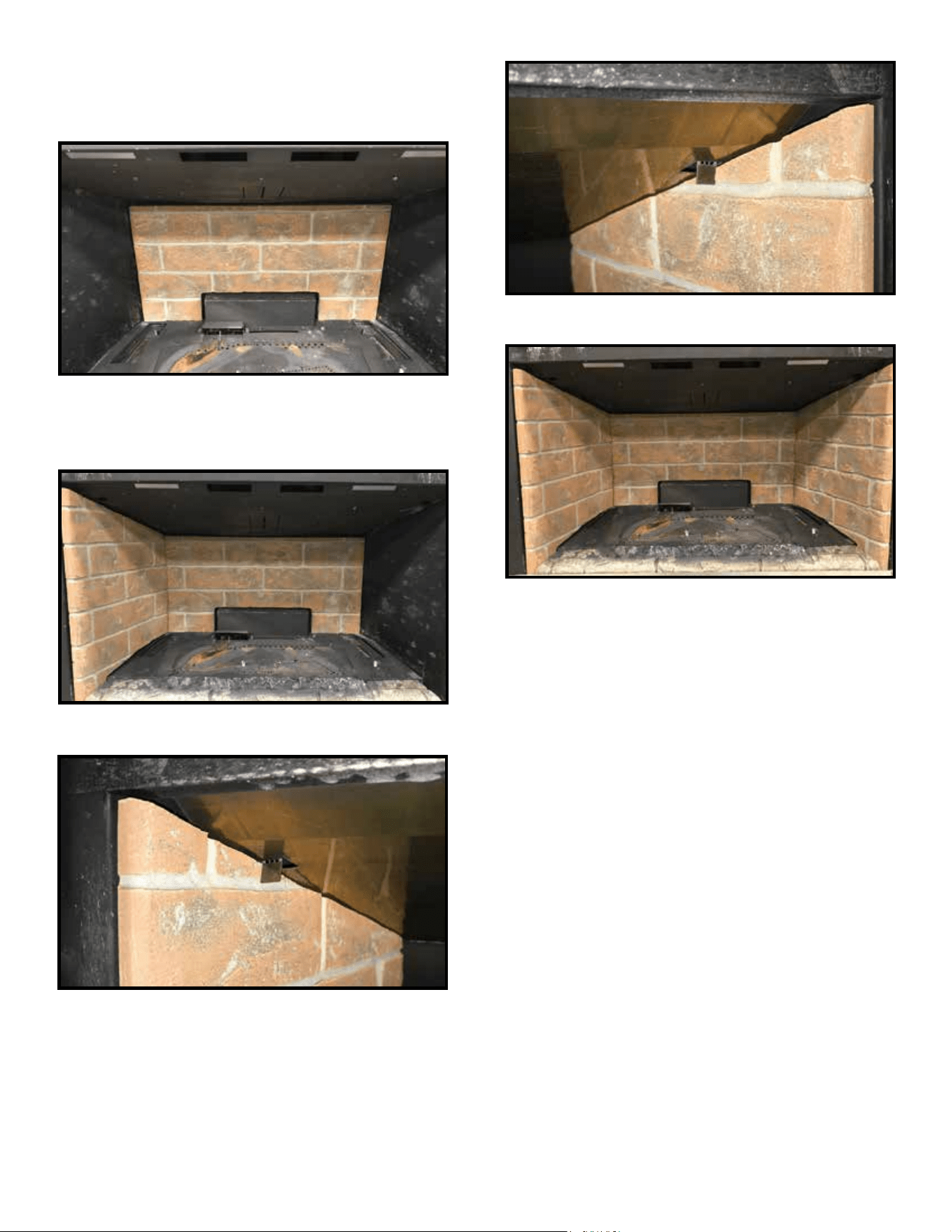
42
Majestic • TRILLIANT25IN/IL, TRILLIANT30IN/IL, TRILLIANT35IN/IL Installation Manual • 2571-980 Rev. G • 6/24
Figure 4 Back Refractory Installed
Figure 5 Left Refractory Installed
Figure 6 Left Refractory Handbend Tab
Figure 7 Right Refractory Handbend Tab
Figure 8 Refractory Kit Installed
3. Install left and right refractory, bend down tabs to hold
in place. See Figures 5, 6 & 7.
2. Install back refractory. See Figure 4.
Be sure to hold back refractory in upright position until
side panels get installed.
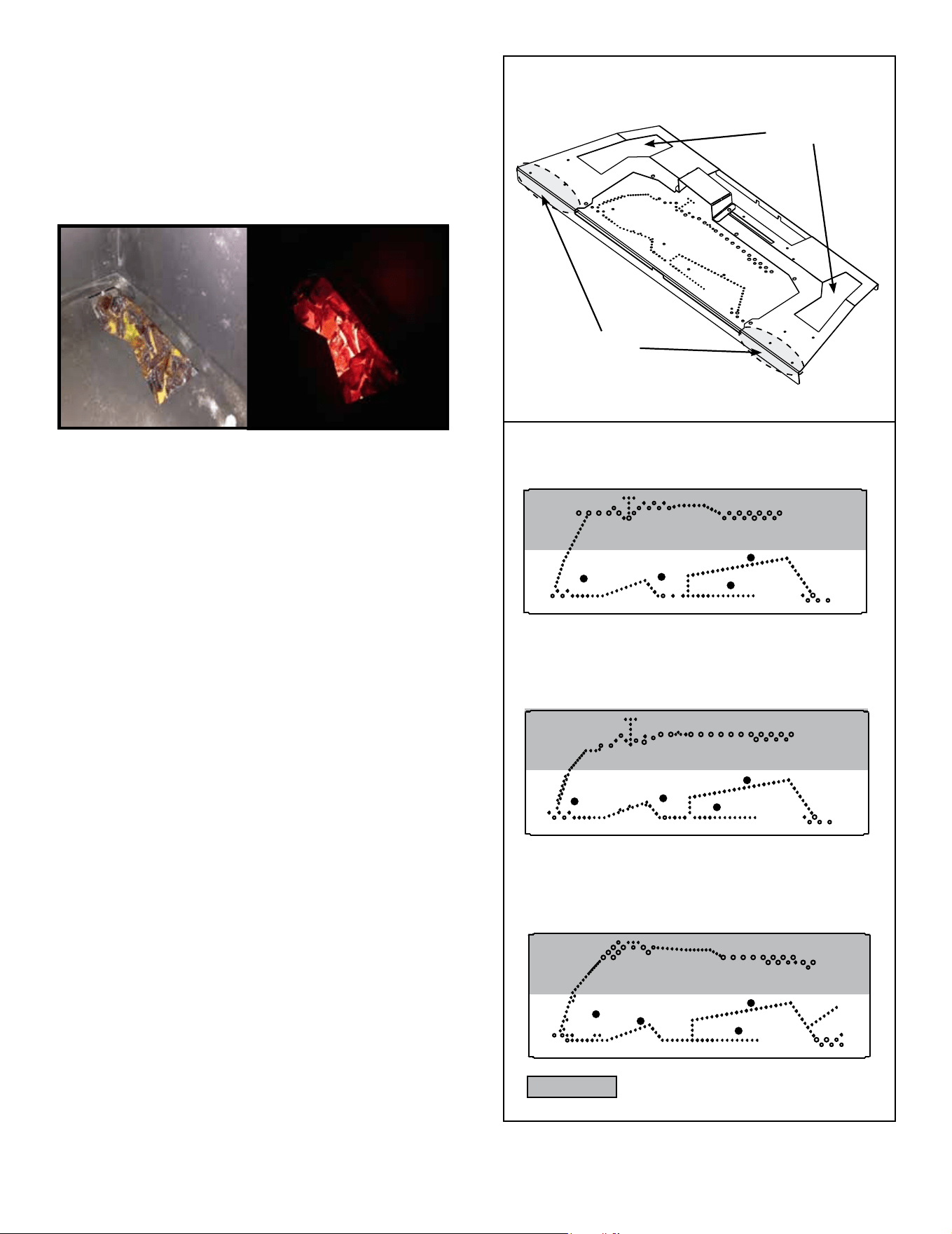
43
Majestic • TRILLIANT25IN/IL, TRILLIANT30IN/IL, TRILLIANT35IN/IL Installation Manual • 2571-980 Rev. G • 6/24
H. Ember Placement
WARNING! Risk of Explosion! Follow ember placement
instructions in manual. Replace ember material annually.
Improperly placed embers interfere with proper burner op-
eration.
Ember material is shipped with this gas appliance. To place
the ember material:
• Embers CANNOT be placed directly over burner ports
that are indicated in Figure 9.4 or in pilot area as indicated
in Figure 9.4.
• Embers may be placed on the ports in areas indicated in
Figure 9.4. These embers must be placed loosely over
the port holes, not pressed down on or into the holes.
Create a single layer, no more than 1/4 inch thick.
• Failure to follow this procedure will likely cause lighting
and sooting problems.
• Save the remaining ember materials for use during
appliance servicing. The embers provided should be
enough for 3 to 5 applications.
Figure 9.4 Placement of Embers
F. Ember Rocks Placement
• Ember rocks shipped in the appliance manual bag.
• If desired, ember rocks can be used to reduce the
intensity of the accent lighting.
• The heavier the ember rocks is applied the more the
intensity of the accent lighting is reduced.
Figure 9.3 Accent Light with Ember Rocks
G. Mystic Embers Placement
WARNING! Risk of Explosion! Follow mystic ember
placement instructions. DO NOT place mystic embers on
burner. Improperly placed mystic embers interferes with
proper burner operation.
Mystic embers is shipped with this gas appliance. To place
the embers:
• Embers CANNOT be placed on the burner.
• Place embers in front of and to the sides of the burner.
• Use mystic embers to mask transition between base
refractory and base pan. See Figure 9.4.
NO EMBERS
TRILLIANT25I
TRILLIANT30I
TRILLIANT35I
MYSTIC
EMBERS
EMBER
ROCKS
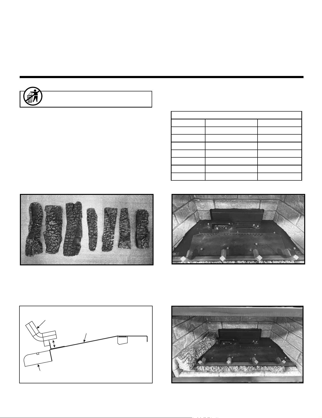
44
Majestic • TRILLIANT25IN/IL, TRILLIANT30IN/IL, TRILLIANT35IN/IL Installation Manual • 2571-980 Rev. G • 6/24
I. Install the Log Assembly
LOG PLACEMENT INSTRUCTIONS
Figure 1. Log Identication - EXCURSION-I, TRILLIANT25I
Figure 4. Log #1 Installed
CAUTION: Logs are fragile, handle with care.
NOTICE: To simplify the installation process, use
Figure 1 to positively identify each individual log
before beginning installation.
Figure 2. Empty Firebox with Front Hearth Installed
LOG #1: Set log #1 against left refractory and slide back until the burnout end touches the back refractory. Rotate log so
the burnout end touches pin A and bark end touches left refractory. See Figure 4.
LOGS-2537, LOGS-2538, LOGS-2539
MODELS: EXCURSION-I, EXCURSION-II, EXCURSION-III,
TRILLIANT25I, TRILLIANT30I, TRILLIANT35I
Installation Instructions
CAUTION! Risk of Cuts or Abrasions. Wear protective
gloves and safety glasses during installation.
Leave this manual with party responsible for use
and operation.
MODEL: EXCURSION-I, TRILLIANT25I
11
AA
BB
11
22
33 44 55
66
CC
DD
EE
FF
GG
AA
77
EXCURSION-I SRV LOGS
LOG ID SRV PART # MOLDED LOG #
1 SRV2537-711 37-1
2 SRV2537-712 37-2
3 SRV2537-713 37-3
4 SRV2538-714 37-4
5 SRV2537-715 37-5
6 SRV2537-716 37-6
7 SRV2537-717 37-7
HH
GRATE
7/8 in.
BASE REFRACTORY
BASEPAN
Figure 3. Side Prole Grate Location Reference

45
Majestic • TRILLIANT25IN/IL, TRILLIANT30IN/IL, TRILLIANT35IN/IL Installation Manual • 2571-980 Rev. G • 6/24
LOG #3: Place lower right side of Log #3 against pin F and burnout end of log #3 on at spot of Log #2. Slide the burnout
end of log back until it contacts refractory. The right end of the log will also contact the right side refractory. See Figure 6.
Figure 8. #5 Installed
Figure 6. Log #3 Installed
LOG #7: Locate the bark to burnout transition on Log #7. Place transition over grate tine and burnout end of log in notch
of Log #4. See Figure 10.
Figure 9. Log #6 Installed
Figure 10. Log #7 Installed
Figure 7. Log #4 Installed
22
LOG #4: Place the left tip of Log #4 against pin B and lay at on the burner. Rotate the log forward until it contacts both
pin C and pin E. Log will contact all 3 pins. See Figure 7.
66
33
FF
44
44
CC
BB
EE
33
DD
LOG #5: Notch on burnout end of Log #5 rests on grate tine, bark end rests on notch of Log #1. Slide burnout end of log
back until it touches Log #4. See Figure 8.
Figure 5. Log #2 Installed
11
22
GG
HH
LOG #2: Place the bottom right end of log #2 against pins G & H and the left end of the log on the at spot of log #1. Back
side of log will be pushed up against the air scoop. See Figure 5.
LOG #6: Place the burnout tip of Log #6 against pin D and the end of grate tine. Place the bark end on the at spot of Log
#3. See Figure 9.
11
55
44
77
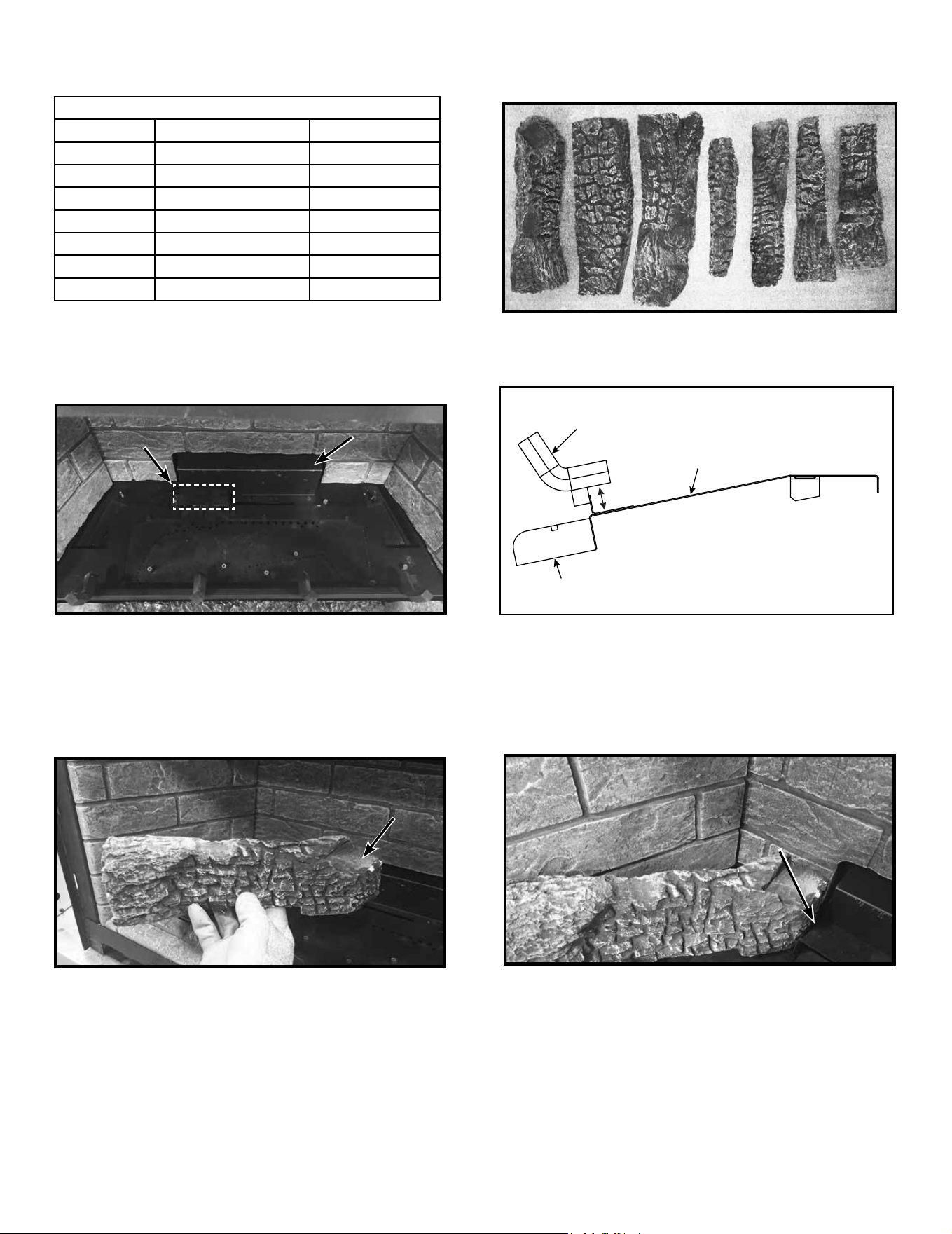
46
Majestic • TRILLIANT25IN/IL, TRILLIANT30IN/IL, TRILLIANT35IN/IL Installation Manual • 2571-980 Rev. G • 6/24
Figure 12. Empty Firebox with Front Hearth Installed
Figure 14. Log #1 Cutout Figure 15. Log #1 Against Pilot Hood
MODELS: EXCURSION-II, TRILLIANT30I
LOG #1: Place cutout area of log #1 against the left side of the pilot hood. Lower the bark end of the log down until it rests
on the horizontal beam of the log grate. It will sit between tine #1 and the refractory. The transition from bark to burnout
will line up with the grate bar. Ensure that the cutout section of the log is pushed up against the side of the pilot hood. See
Figures 14, 15 and 16.
CUTOUTCUTOUT
AA
BB
Figure 11. Log Identication - EXCURSION-II, TRILLIANT30I
11
22
33
44
55
NOTICE: To simplify the installation process, use
Figure 11 to positively identify each individual log
before beginning installation.
66
77
C C
DD
EE
FF
PILOT HOODPILOT HOOD
PILOT HOODPILOT HOOD
11
11
AIR SCOOPAIR SCOOP
EXCURSION-II SRV LOGS
LOG ID SRV PART # MOLDED LOG #
1 SRV2538-711 38-1
2 SRV2538-712 38-2
3 SRV2538-713 38-3
4 SRV2538-714 38-4
5 SRV2538-715 38-5
6 SRV2538-716 38-6
7 SRV2538-717 38-7
GRATE
7/8 in.
BASE REFRACTORY
BASEPAN
Figure 13. Side Prole Grate Location Reference
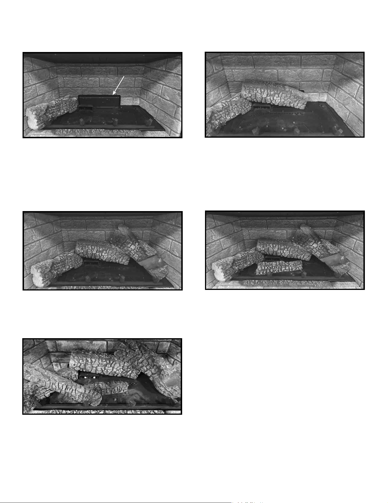
47
Majestic • TRILLIANT25IN/IL, TRILLIANT30IN/IL, TRILLIANT35IN/IL Installation Manual • 2571-980 Rev. G • 6/24
Figure 19. Log #4 Installed
LOG #4: Place the left tip of Log #4 against pin A and lay at on the burner. Rotate the log forward until it contacts both pin
B and pin D. Log will contact all 3 pins. See Figure 19.
Figure 18. Log #3 Installed
22
44
33
LOG #3: Place lower right side of Log #3 against pin F and burnout end of Log #3 on at spot of Log #2. Slide the burnout
end of log back until it contacts the back refractory. The back of right side of log will contact the right side refractory. See
Figure 18.
Figure 20. Log #5 Installed
55
FF
AA
BB
DD
LOG #5: Notch on burnout end of Log #5 rests on grate tine, bark end rests on notch of Log #1. Slide burnout end of log
back until it touches Log #4. See Figue 20.
11
Figure 16. Log #1 Installed
Figure 17. Log #2 Installed
LOG #2: Place the bottom right end of Log #2 against pin E and the left end of the log on the at spot of Log #1. Back side
of log will be pushed up against the air scoop. See Figure 17.
AIR SCOOPAIR SCOOP
11
11
22
EE
44
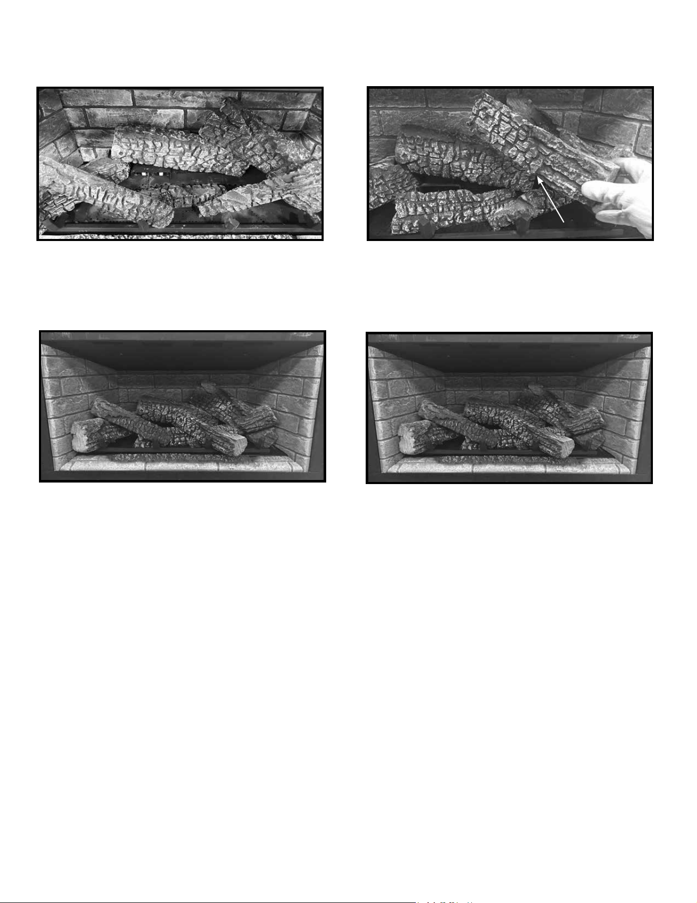
48
Majestic • TRILLIANT25IN/IL, TRILLIANT30IN/IL, TRILLIANT35IN/IL Installation Manual • 2571-980 Rev. G • 6/24
Figure 21. Log #6 Installed
Figure 22. Log #7
66
33
77
Figure 23. Log #7 Installed
77
44
Figure 24. Complete Log Set
LOG #6: Place the burnout tip of Log #6 against pin C and position between two rows of burner parts. Place the bark end
on the at spot of Log #3. See Figure 21.
C C
LOG #7: Locate the notch on Log #7. See Figure 22. Place notch over grate tine and burnout end of log on notch of Log
#4. See Figure 23.
NOTCHNOTCH
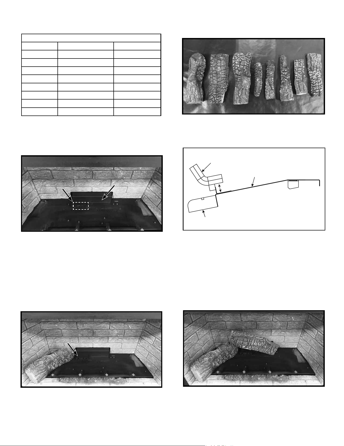
49
Majestic • TRILLIANT25IN/IL, TRILLIANT30IN/IL, TRILLIANT35IN/IL Installation Manual • 2571-980 Rev. G • 6/24
Figure 26. Empty Firebox with Front Hearth Installed
Figure 28. Log #1 Installed Figure 29. Log #2 Installed
LOG #1: Place burnout end of log #1 against the left side of pin B and the bark end between the grate and refractory. Slide
the log back until it contacts the back of the rebox. Rotate the log (bark end) clockwise unit it contacts the side refractory.
The log will be in contact with the rebox back, pin B and the side refractory. See Figure 28.
AA
BB
Figure 25. Log Identication - EXCURSION-III, TRILLIANT35I
11
22 33
44
55
NOTICE: To simplify the installation process, use
Figure 25 to positively identify each individual log
before beginning installation.
66
77
C C
DD
FF
GG
PILOT HOODPILOT HOOD
11
11
AIR SCOOPAIR SCOOP
88
EE
PILOT HOODPILOT HOOD
22
FF
LOG #2: Place the bottom right end of log #2 against pin F and the left end of the log on the at spot of log #1. Push the
log back so that it contacts the air scoop. See Figure 29.
MODELS: EXCURSION-III, TRILLIANT35I
EXCURSION-III SRV LOGS
LOG ID SRV PART # MOLDED LOG #
1 SRV2539-711 39-1
2 SRV2539-712 39-2
3 SRV2539-713 39-3
4 SRV2539-714 39-4
5 SRV2538-715 39-5
6 SRV2539-716 39-6
7 SRV2538-717 39-7
8 SRV2539-718 39-8
HH
BB
GRATE
7/8 in.
BASE REFRACTORY
BASEPAN
Figure 27. Side Prole Grate Location Reference
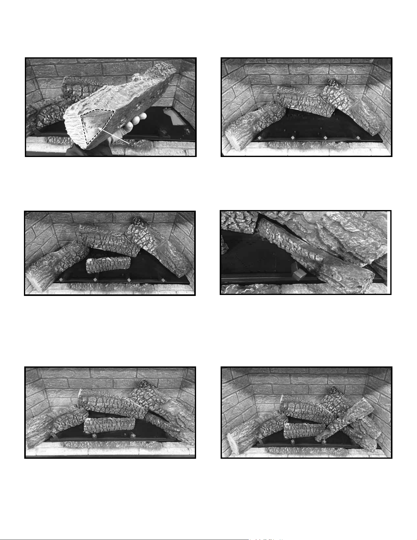
50
Majestic • TRILLIANT25IN/IL, TRILLIANT30IN/IL, TRILLIANT35IN/IL Installation Manual • 2571-980 Rev. G • 6/24
Figure 30. Log #3
Figure 31. Log #3 Installed
LOG #3: Place lower right side of log #3 against pin H and burnout end of log #3 on at spot of log #2. Rotate the log so
the at spot on the back side is ush against the right side refractory. Slide the burnout end of log #3 back until it contacts
the back refractory. See Figure 30 & 31.
33
22
HH
33
FLAT SPOTFLAT SPOT
Figure 33. Log #5 Installed
Figure 34. Log #5 Installed Figure 35. Log #6 Installed
55
33
66
Figure 32. Log #4 Installed
44
55
33
LOG #4: Place the left tip of log #4 against pin A and lay at on the burner. Rotate the log forward until it contacts both pin
C and pin E. Log will contact all 3 pins. See Figure 32.
CC
LOG #5: The tip of the burnout end of log #5 will contact pin G and the bark end will rest on the grate between tine #4 and
log #3. See Figures 33 and 34.
G G
EE
AA
44
44
G G
LOG #6: Place the burnout tip of log #6 against pin D and the end of tine #3. Place the bark end in the notch on log #3.
See Figure 35.
D D
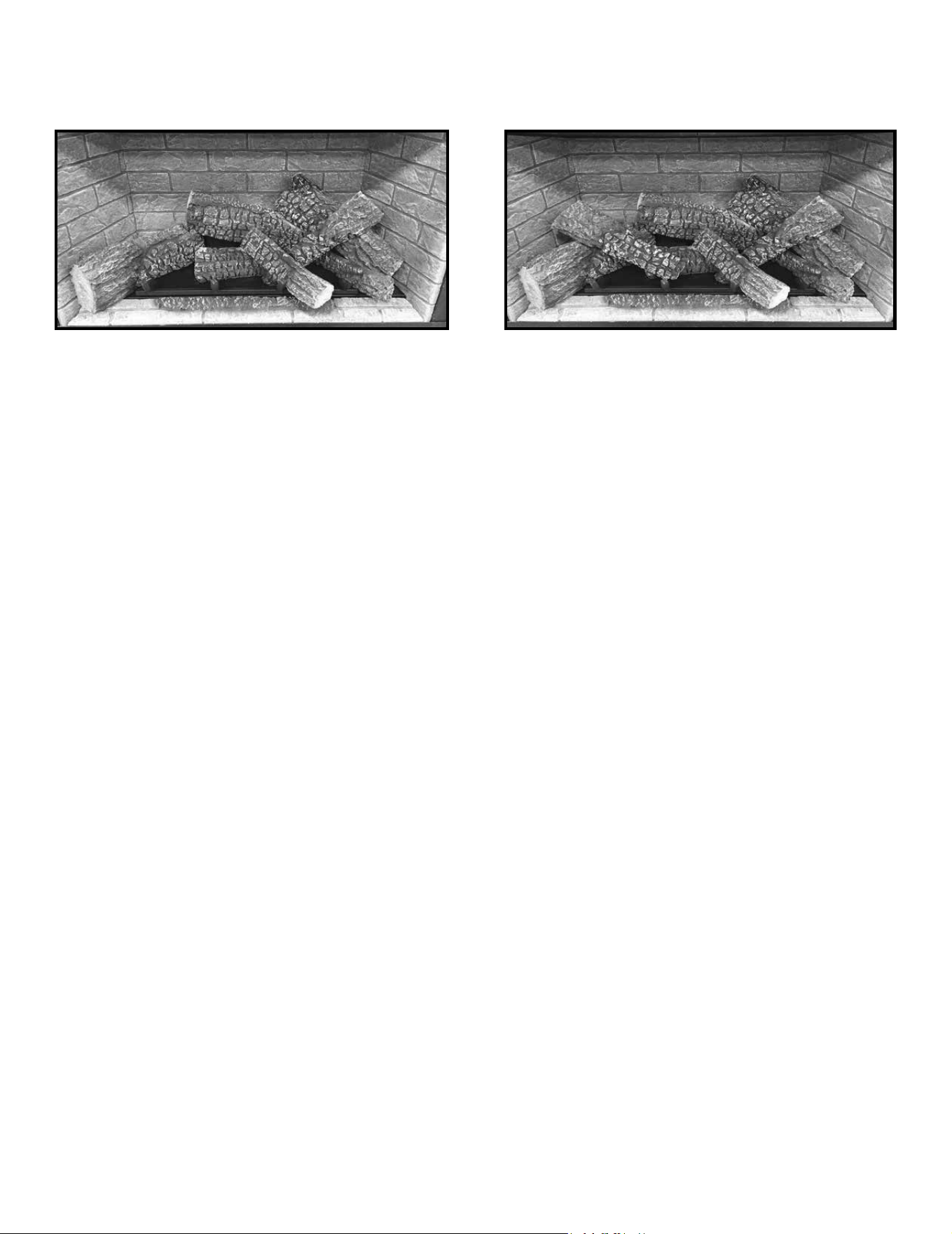
51
Majestic • TRILLIANT25IN/IL, TRILLIANT30IN/IL, TRILLIANT35IN/IL Installation Manual • 2571-980 Rev. G • 6/24
2538-935G
Figure 37. Log #8 Installed.
44
Figure 36. Log #7 Installed
7744
11
LOG #7: Locate the notch on log #7. Place notch over grate tine and burnout end of log in notch of log #4. See Figure 36.
88
LOG #8: Notch on burnout end of log #8 rests on grate tine, bark end rests on notch of log #1. See Figure 37.
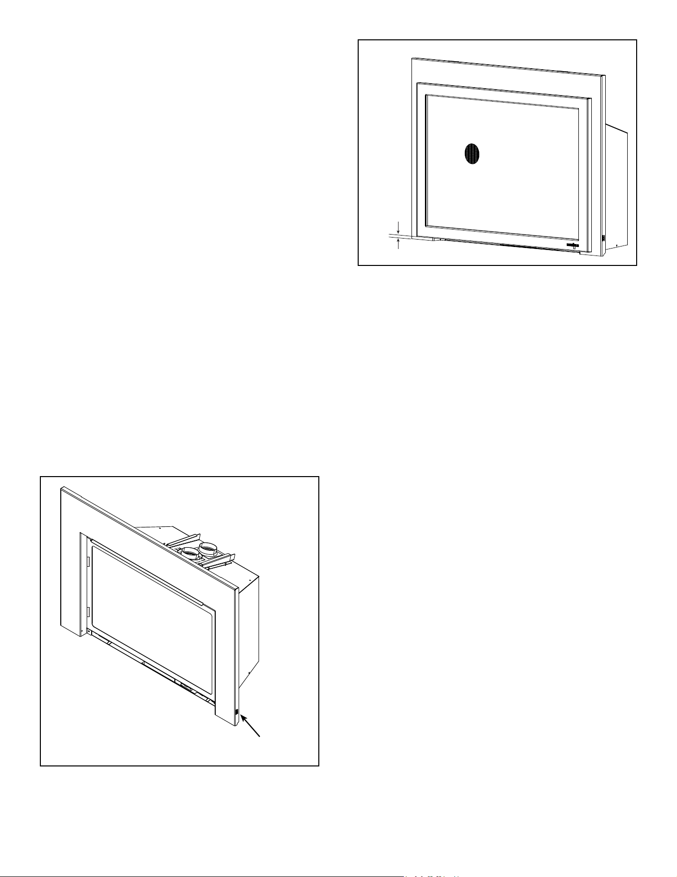
52
Majestic • TRILLIANT25IN/IL, TRILLIANT30IN/IL, TRILLIANT35IN/IL Installation Manual • 2571-980 Rev. G • 6/24
J. Install Decorative Barrier Front and
Surround
A decorative barrier front and surround is required to
complete this installation. Installation instructions are
included with the decorative barrier front and surround.
Consult your dealer for a list of decorative barrier front
and surround options.
WARNING! Risk of Fire! Install ONLY doors or fronts
approved by Hearth & Home Technologies. Unapproved
doors or fronts may cause replace to overheat.
This fireplace has been supplied with an integral
barrier to prevent direct contact with the xed glass
panel. DO NOT operate the replace with the barrier
removed.
Contact your dealer or Hearth & Home Technologies if
the barrier is not present or help is needed to properly
install one.
For more information refer to the instructions supplied with
your decorative barrier front.
See Figure 9.5 for Reset Switch Detail. The Reset Switch
included with the surround needs to be wired to the
appliance. Reference front/surround instructions (included
with the decorative barrier front) and wiring diagram in
Figure 6.2.
• Reset switch must be installed and in the “ON” position
for appliance to operate.
Figure 9.5 Surround Reset Switch
NOTICE: 1/2 inch gap must be maintained or components
will overheat.
RESET SWITCH
1/2 in.
Figure 9.6 Required 1/2 in. Gap
NOTE: For on site custom surround details, see instruc-
tions included with the surround.

53
Majestic • TRILLIANT25IN/IL, TRILLIANT30IN/IL, TRILLIANT35IN/IL Installation Manual • 2571-980 Rev. G • 6/24
K. Appliance Break-In
Follow the initial break-in procedure below to cure the
materials used to manufacture the replace and the
nishing materials around it.
• The fireplace should be run three to four hours
continuously on high ame.
• Turn the replace off and allow it to cool completely.
• Remove xed glass assembly. See Section 9.A.
• Clean xed glass assembly.
• Replace the xed glass assembly and run continuously
on high an additional 12 hours.
Note: The IntelliFire Touch system has a safety feature
that automatically shuts down the replace after 9 hours
of continuous operation without receiving a command from
the remote control. If this occurs, restart the appliance.
NOTICE! Open windows for air circulation during re-
place break-in.
• Some people may be sensitive to smoke and odors.
• Smoke detectors may activate.
L. Heat Management
Heat Output
Heat Output is managed through the RC400 remote con-
trol that comes standard with the replace.
• Turn the appliance on and off.
• Adjust the height of the ame by varying the input using
the remote control.
• Adjust the fan speed.
For more information, see the instructions that accompany
the remote control.
NOTICE! Set the fan speed to high on the RC400 remote
control during the rst three to four hours of break-in
operation. This break-in will ensure optimum speed control
of the fans during subsequent use.
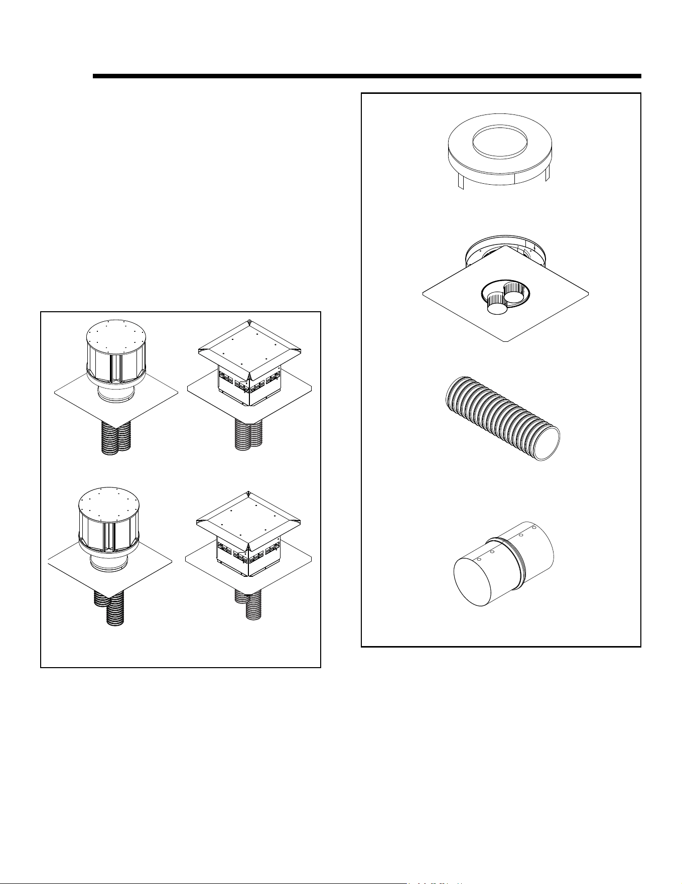
54
Majestic • TRILLIANT25IN/IL, TRILLIANT30IN/IL, TRILLIANT35IN/IL Installation Manual • 2571-980 Rev. G • 6/24
10 10
Reference Materials
A. Vent Components
Direct Vent Flex Liner Kits (see Figure 10.1)
LINK-DV30B: Masonry 3 inch ex liner kit. Expands to 30
feet. Includes: two liners, termination cap and ashing.
LINK-DV4-30B: Masonry 3 inch ex liner kit. Expands to 30
feet and 4 feet respectively. Includes: two liners, termination
cap and ashing.
LINKSQC-DV30, LINKSQB-DV30: Masonry 3 inch ex liner
kit. Expands to 30 feet. Includes: two liners, termination
cap and ashing.
LINKSQC-DV4-30, LINKSQB-DV4-30: Masonry 3 inch
ex liner kit. Expands to 30 feet and 4 feet respectively.
Includes: two liners, termination cap and ashing.
Figure 10.1 Direct Vent Flex Liner Kits
Figure 10.2 Direct Vent Flex Liner Accessory Kits
Direct Vent Flex Liner Accessory Kits. See Figure 10.2.
LINK-ZC-ADPB: Zero clearance chimney adapter
DV-46DVA-GK: Adapter kit - It is permissible to use DV-
46DVA-GK to connect colinear ex vent to SLP vent pipe
to extend the run.
FLEX3-30: One 3 inch exible liner expands to 30 feet.
FLEX-CNCT: Connector kit - 3 inch liner to 3 inch liner,
one connector per kit.
FLEX3-30
LINK-DV30B
LINK-ZC-ADPB
DV-46DVA-GK
FLEX-CNCT
LINK-DV4-30B
LINKSQC-DV30 (COPPER)
LINKSQB-DV30 (BLACK)
LINKSQC-DV4-30 (COPPER)
LINKSQB-DV4-30 (BLACK)
Reference price book for SLP
components.
Note: No Horizontal Termi-
nation allowed.
95070310 (FLEX LINER 3X10)
95070325 (FLEX LINER 3X25)

55
Majestic • TRILLIANT25IN/IL, TRILLIANT30IN/IL, TRILLIANT35IN/IL Installation Manual • 2571-980 Rev. G • 6/24
Printed in U.S.A. - Copyright 2024
Majestic, a brand of Hearth & Home Technologies
7571 215
th
Street West, Lakeville, MN 55044
www.majesticproducts.com
Please contact your Majestic dealer with any questions or concerns.
For the location of your nearest Majestic dealer,
please visit www.majesticproducts.com.
Remote Controls, Wall Controls and Wall
Switches
Follow the instructions supplied with the control installed
to operate your replace:
For safety:
• Install a switch lock or a wall/remote control with child
protection lockout feature.
• Keep remote controls out of reach of children.
See your dealer if you have questions.
B. Accessories
Install approved accessories per instructions included
with accessories. Contact your dealer for a list of ap-
proved accessories.
WARNING! Risk of Fire and Electric Shock! Use ONLY
Hearth & Home Technologies-approved optional acces-
sories with this appliance. Using non-listed accessories
could result in a safety hazard and will void the warranty.
Halogen Lights
Halogen Lights are factory installed. No additional set up
is required.
Note: Not offered with 25 in. model.
Fan
Fan is factory installed. No additional set up is required.
Refractory
Refractory is factory installed. No additional set up is
required.