INSTALLATION AND OPERATING INSTRUCTIONS
for all
HS, and HIS Warming Cabinets
809-195A Rev D. 02/05/2026
3779 CHAMPION BLVD, WINSTON-SALEM, NC 27105
Phone: (888) 845-9800 | Fax: (800) 253-5168 | Web: victoryrefrigeration.com
SEE BACK COVER FOR
WARRANTY REGISTRATION

User Manual for HS and HIS Warming Cabinets Victory
Rev. 02/26Victory2
WELCOME
Contents
Safety .. .. .. .. .. .. .. .. .. .. .. .. .. .. .. .. .. .. .. .. .. .. .. .. .. .. .. ..3
Important Information .. .. .. .. .. .. .. .. .. .. .. .. .. .. .. .. .. ..5
Product Information . .. .. .. .. .. .. .. .. .. .. .. .. .. .. .. .. .. .. ..6
Clearance and Placement.. .. .. .. .. .. .. .. .. .. .. .. .. .. .. .. ..7
Unpacking and Set Up . .. .. .. .. .. .. .. .. .. .. .. .. .. .. .. .. .. ..8
Set Up for Units Without Legs/Casters . .. .. .. .. .. .. .. ..9
Shelf Installation.. .. .. .. .. .. .. .. .. .. .. .. .. .. .. .. .. .. .. .. .. ..10
Electrical . .. .. .. .. .. .. .. .. .. .. .. .. .. .. .. .. .. .. .. .. .. .. .. .. .. ..11
Preheating & Food Storage.. .. .. .. .. .. .. .. .. .. .. .. .. .. .. ..12
Recommended Food Storage Periods . .. .. .. .. .. .. .. .. ..13
Using the Unit . .. .. .. .. .. .. .. .. .. .. .. .. .. .. .. .. .. .. .. .. .. .. .. 14
Carel Applica App .. .. .. .. .. .. .. .. .. .. .. .. .. .. .. .. .. ..15
Sequence of Operations .. .. .. .. .. .. .. .. .. .. .. .. .. ..17
Electronic Controller Display . .. .. .. .. .. .. .. .. .. .. ..18
Changing the Operating Set Point . .. .. .. .. .. .. .. ..21
Alarm Codes . .. .. .. .. .. .. .. .. .. .. .. .. .. .. .. .. .. .. .. .. ..23
Cleaning and Maintenance . .. .. .. .. .. .. .. .. .. .. .. .. .. .. ..27
Methods For Cleaning Stainless Steel .. .. .. .. .. .. .. .. ..28
Help . .. .. .. .. .. .. .. .. .. .. .. .. .. .. .. .. .. .. .. .. .. .. .. .. .. .. .. .. ..29
Help Continued.. .. .. .. .. .. .. .. .. .. .. .. .. .. .. .. .. .. .. .. .. .. ..30
For The Service Tech - Wiring Diagram . .. .. .. .. .. .. .. ..31
Limited Warranty .. .. .. .. .. .. .. .. .. .. .. .. .. .. .. .. .. .. .. .. ..32
Limited Warranty (continued).. .. .. .. .. .. .. .. .. .. .. .. .. ..33
Important Information
• PLEASE READ THESE INSTRUCTIONS CAREFULLY
BEFORE INSTALLING OR USING, IF RECOMMENDED
PROCEDURES ARE NOT FOLLOWED, WARRANTY
CLAIMS MAY BE DENIED.
• Your warranty registration information is located with
this manual. Please complete the card and submit
it to Victory within TEN days of installation. Failure
to properly register equipment may limit or void the
warranty.
• Victory reserves the right to change specications
and product design without notice. Such revisions
do not entitle the buyer to corresponding changes,
improvements, additions, or replacements for
previously purchased equipment.
Congratulations on your purchase of Victory food service
equipment. Every employee welcomes you to the family
of satised Victory customers.
From the earliest stages of production design, to focused
steps in fabrication and assembly, rigid standards of
quality are maintained by our sta of skilled employees.
Victory strives to supply superior products through strict
quality control guidelines exceeding industry standards,
this means that each unit, given the proper maintenance
will provide years of trouble free experience to its owner.
Additionally, Victory food service equipment has one
of the best warranties in the food service industry, and
backed by a professional sta of service technicians
across the country.
We thank you for your choice and condence in Victory
Equipment.
User Manual for HS and HIS Warming Cabinets Victory
Rev. 02/26 Victory 3
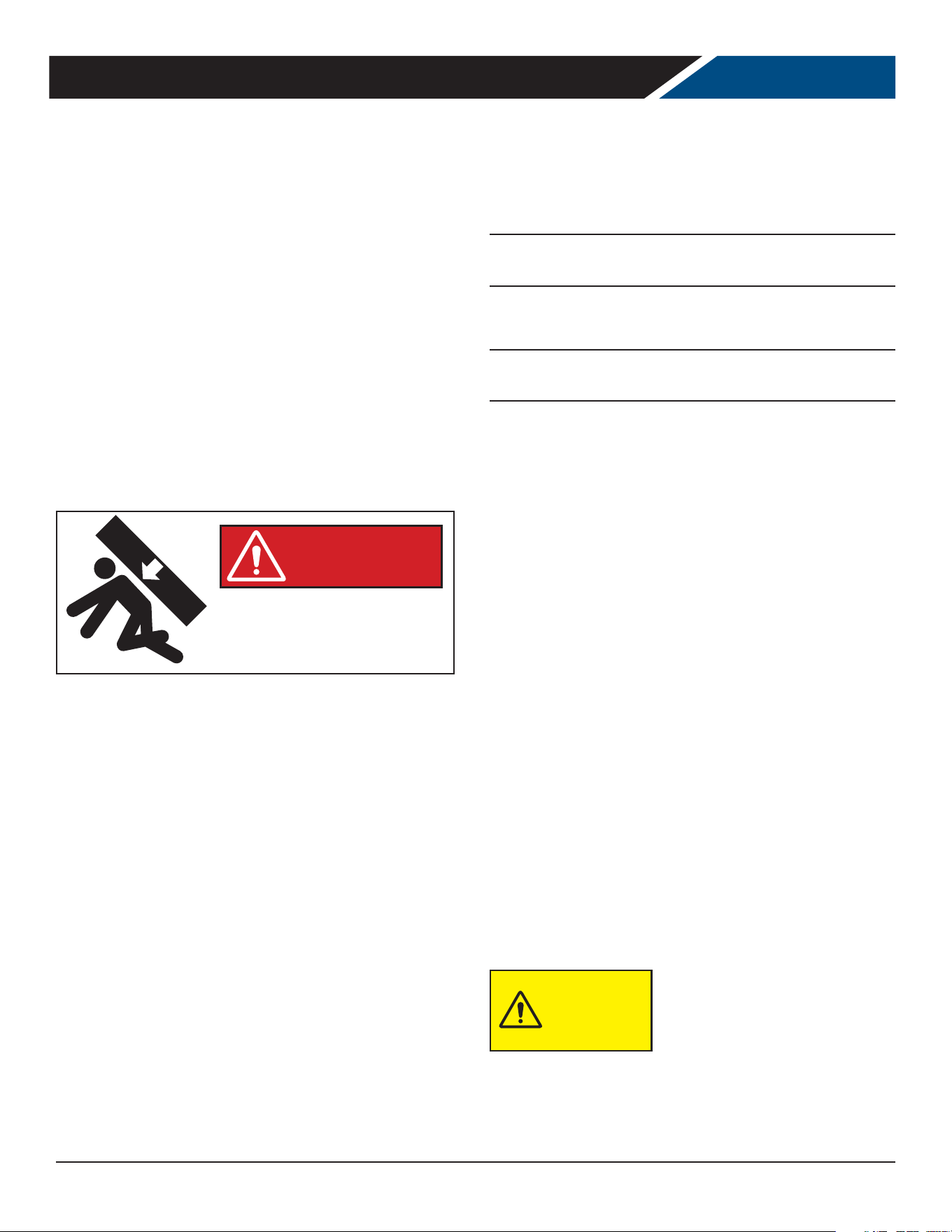
SAFETY
Observe the Caution and Warning notices. They are indicators of
important safety information. Keep this manual for future reference.
Important Information to Add
Record the model number, serial number and the date of installation here for future reference. The model and serial
numbers are on the unit's serial number dataplate, which is located on the left inside wall.
Model Number
Serial Number
Date of Installation
Purchased From
CAUTION
WARNING
CAUTION
CAUTION
This appliance has been designed with your safety in mind. It has many features to keep you from being harmed. However,
safe operation and maintenance are your responsibilities. This appliance is not intended for use by persons (including
children) with reduced physical, sensory or mental capabilities, or lack of experience and knowledge, unless they have
been given supervision or instruction concerning use of the appliance by a person responsible for their safety.
Children should be supervised to ensure that they do not play with the appliance.
Use: When using this unit, please:
• Move it carefully. If on casters be sure the casters
do NOT run over the power cord.
• Lock the casters when in use.
• Seek help. This machine is heavy! Be sure to move
with enough help to avoid tipping or dropping the
cabinet.
• Prevent children from playing in or on the cabinet.
Persons unable to use this product must be
prevented access.
• Follow all instructions. There are many safety
labels and directions on the unit. Heed them.
• Watch your ngers. There may be pinch points near
the door hinges.
User Manual for HS and HIS Warming Cabinets Victory
Rev. 02/26Victory4
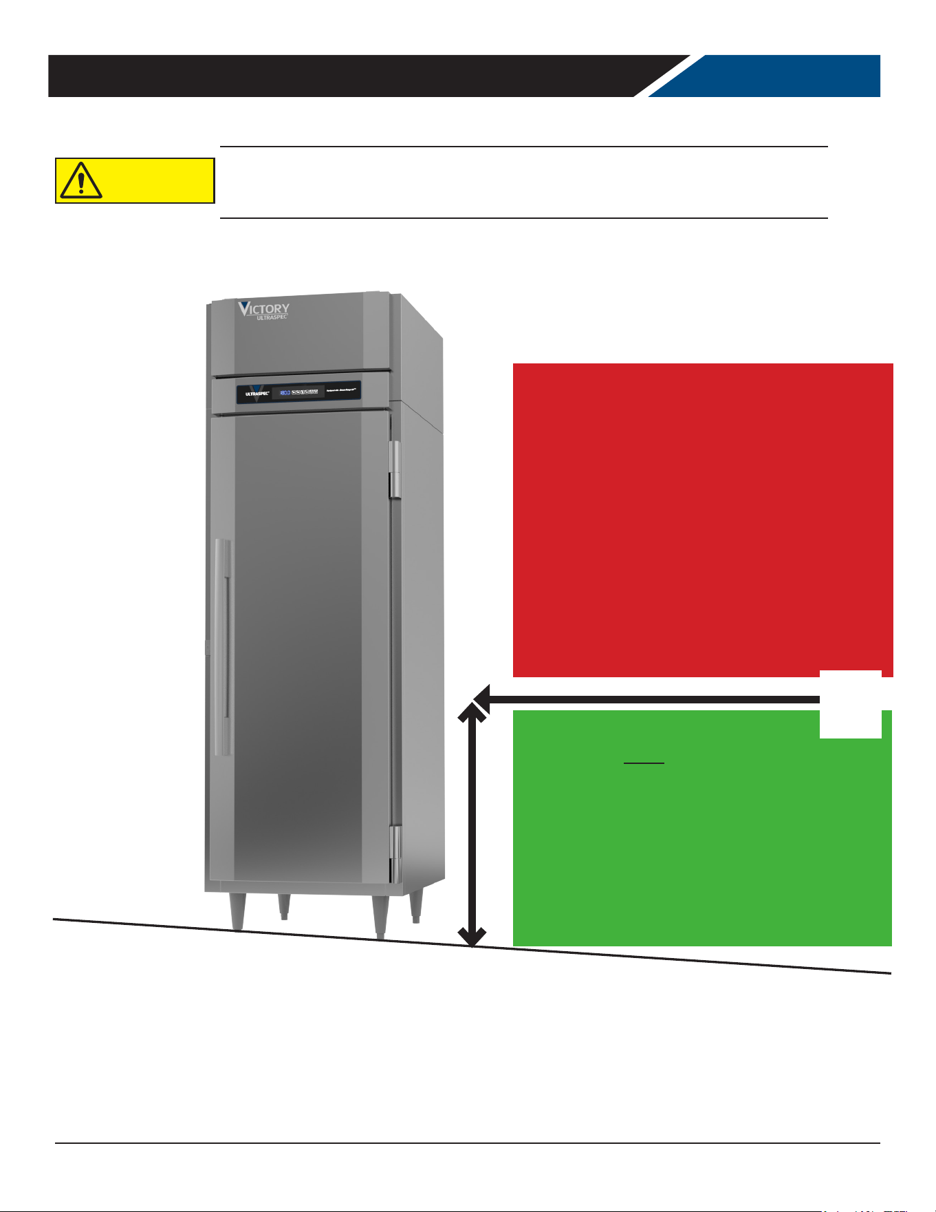
CAUTION: If it is necessary to move the Cabinet after removal from the skid, remove all
doors and carefully push the unit at a point of no more than 36” from the bottom to avoid
damage.
CAUTION
SAFETY
Push ONLY below the 36 inch / .91 meter height
Height
will vary
by model
Do NOT push in this area.
User Manual for HS and HIS Warming Cabinets Victory
Rev. 02/26 Victory 5
IMPORTANT INFORMATION
This unit is intended to be used in a commercial
application. That includes bars and restaurants.
If installed in a residence some commercial service
companies may not be able to service it on site.
The manufacturer has designed and produced this
machine with the nest in materials. The manufacturer
assumes no liability for units that have been altered in
any way. Alterations or part substitutions will void the
warranty.
Limitations
The machine is designed for use indoors in a controlled
environment. It must be kept dry, not overheated or
subjected to excessive cold. May only be connected to
a dedicated electrical circuit. Extension cords are not
permitted.
Minimum Maximum
Voltage 208 240
Room Air Temp 60º F 100º F
Agency Approvals
These marks appear on the dataplate or serial tag, located
in the inside of the left wall. The dataplate also contains
the model and serial numbers as well as electrical
requirements.
User Manual for HS and HIS Warming Cabinets Victory
Rev. 02/26Victory6
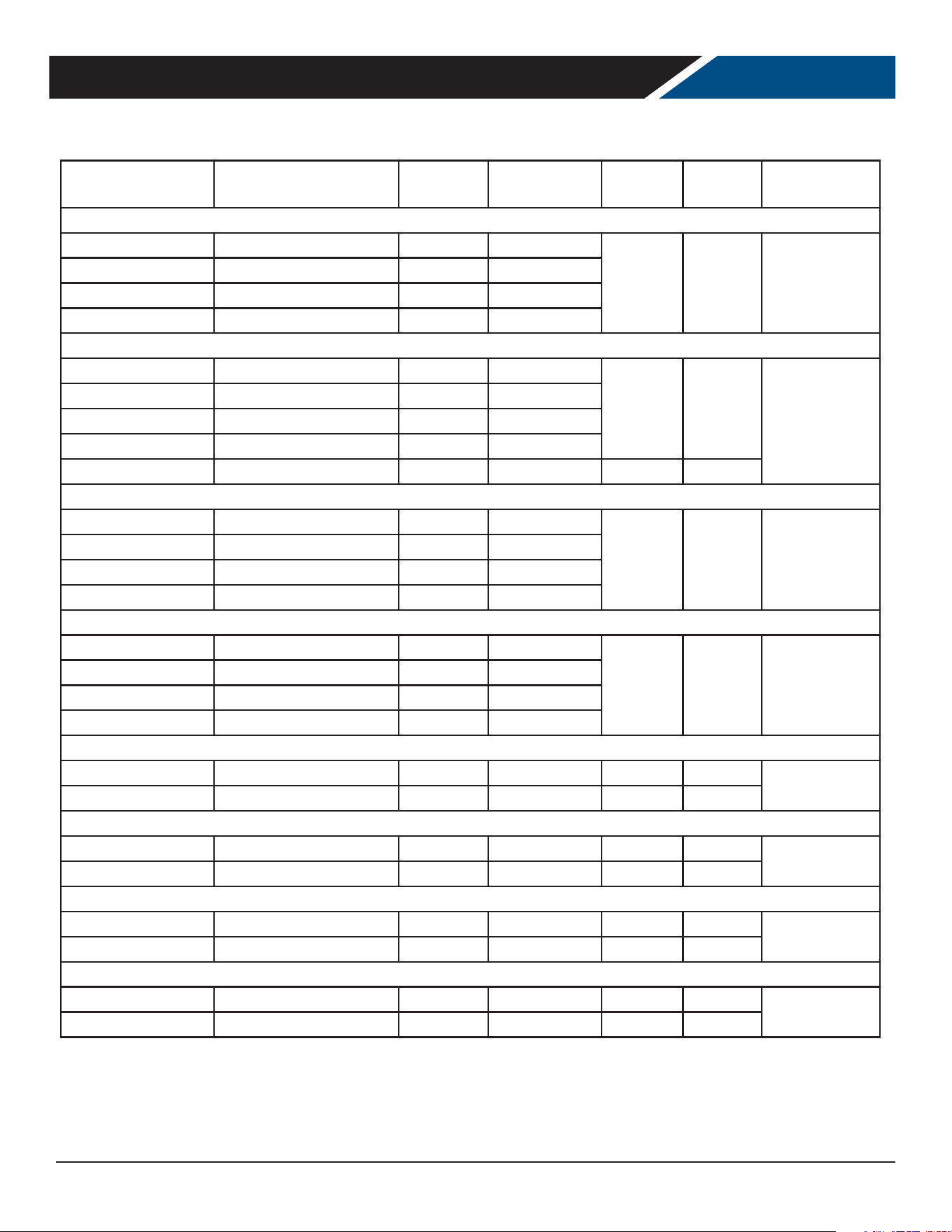
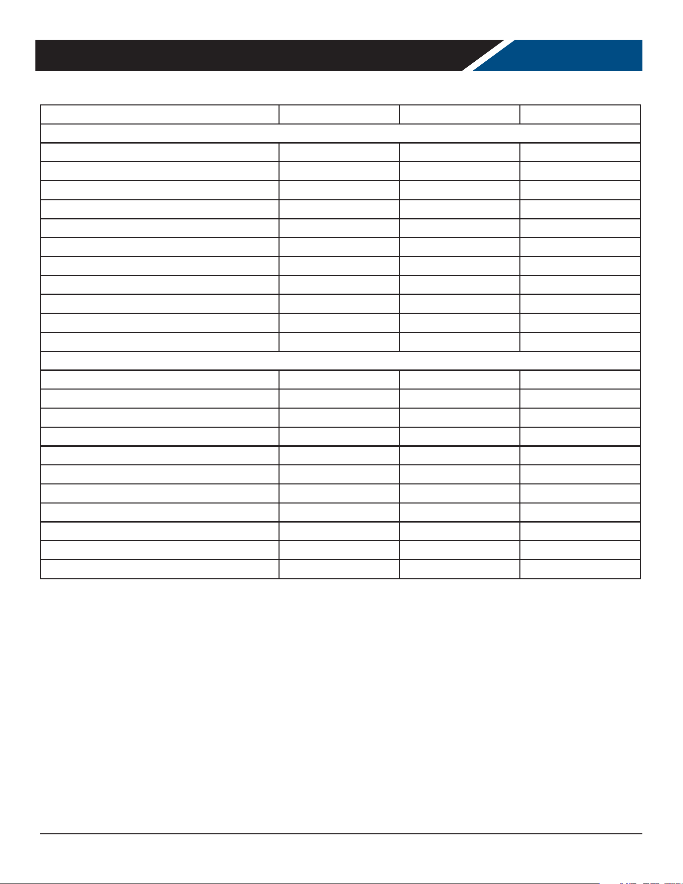
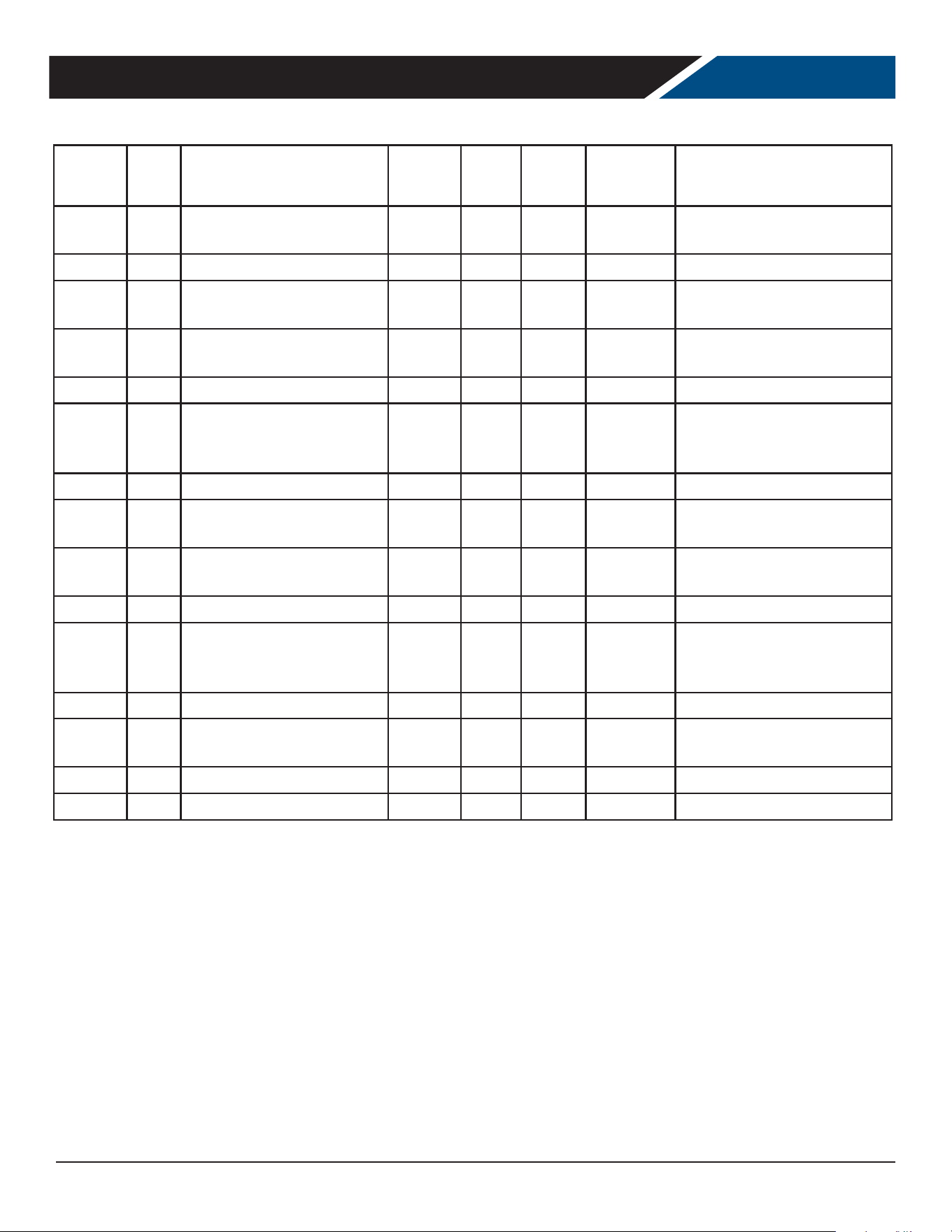
Model
Cabinet Dimensions
w x d x h (Inches)
Doors
Glass or Solid
Door
Full Load
Amps
Heater
Watts
Power Cord
Plug (NEMA)
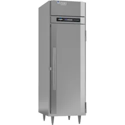
STANDARD UNITS
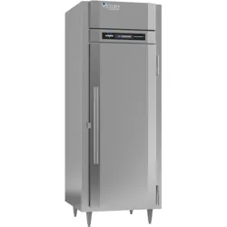
HS(A)-1D-1 26-1/2 X 34-7/8 X 84-1/8 1 SOLID
6.8 1500 6-20P
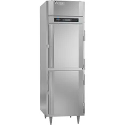
HS(A)-1D-1-HD 26-1/2 X 34-7/8 X 84-1/8 2 SOLID
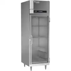
HS(A)-1D-1-G 26-1/2 X 33-5/8 X 84-1/8 1 GLASS
HS(A)-1D-1-HG 26-1/2 X 33-5/8 X 84-1/8 2 GLASS
PASS THRU UNITS
HS(A)-1D-1-PT 26-1/2 X 38-3/4 X 84-1/4 2 SOLID
6.8 1500
6-20P
HS(A)-1D-1-PT-HD 26-1/2 X 38-3/4 X 84-1/4 4 SOLID
HS(A)-1D-1-PT-G 26-1/2 X 36 X 84-1/4 2 GLASS
HS(A)-1D-1-PT-HG 26-1/2 X 36-1/4 X 84-1/4 4 GLASS
HS-2D-1-PT-GD 52 1/8 X 35 3/4 X 84 1/8 4 GLASS 13.0 3000
EXTRA WIDE UNITS
HS(A)-1D-1-EW 31-1/4 X 34-7/8 X 84-1/8 1 SOLID
6.8 1500 6-20P
HS(A)-1D-1-EW-HD 31-1/4 X 34-7/8 X 84-1/8 2 SOLID
HS(A)-1D-1-EW-G 31-1/4 X 33-1/2 X 84-1/8 1 GLASS
HS(A)-1D-1-EW-HG 31-1/4 X 33-5/8 X 84-1/8 2 GLASS
EXTRA WIDE PASS THRU UNITS
HS(A)-1D-1-EW-PT 31-1/4 X 38-3/4 X 84-1/8 2 SOLID
6.8 1500 6-20P
HS(A)-1D-1-EW-PT-HD 31-1/4 X 38-3/4 X 84-1/8 4 SOLID
HS(A)-1D-1-EW-PT-G 31-1/4 X 35-7/8 X 84-1/8 2 GLASS
HS(A)-1D-1-EW-PT-HG 31-1/4 X 36-1/8 X 84-1/8 4 GLASS
STANDARD ROLL-IN UNITS
HIS(A)-1D-1 36 1/2 X 36 1/4 X 84 3/8 1 SOLID 6.8 1500
6-20P
HIS(A)-2D-1 68 7/8 X 36 1/4 X 84 3/8 2 SOLID 13.0 3000
STANDARD ROLL-THRU UNITS
HIS(A)-1D-1-PT 36 1/2 X 40 1/8 X 84 3/8 2 SOLID 6.8 1500
6-20P
HIS(A)-2D-1-PT 68 7/8 X 40 1/8 X 84 3/8 4 SOLID 13.0 3000
EXTRA HIGH ROLL-IN UNITS
HIS(A)-1D-1-XH 36 1/2 X 36 1/4 X 89 7/8 1 SOLID 6.8 1500
6-20P
HIS(A)-2D-1-XH 68 7/8 X 36 1/4 X 89 7/8 2 SOLID 13.0 3000
EXTRA HIGH ROLL-THRU UNITS
HIS(A)-1D-1-PT-XH 36 1/2 X 40 1/8 X 89 7/8 2 SOLID 6.8 1500
6-20P
HIS(A)-2D-1-PT-XH 68 7/8 X 40 1/8 X 89 7/8 4 SOLID 13.0 3000
Height includes casters
• All models are 208-240 volts, 60 Hz AC.
• ALWAYS REFERENCE YOUR EQUIPMENT DATA PLATE AMPS, FOR THE MOST UP TO DATE AND ACCURATE VALUES.
• HS models have stainless steel interiors, HSA models have aluminum interiors
PRODUCT INFORMATION
User Manual for HS and HIS Warming Cabinets Victory
Rev. 02/26 Victory 7
User Manual for TMR Refrigerators Beverage-Air
Rev. 12/21Beverage-Air24
GENERAL PARTS
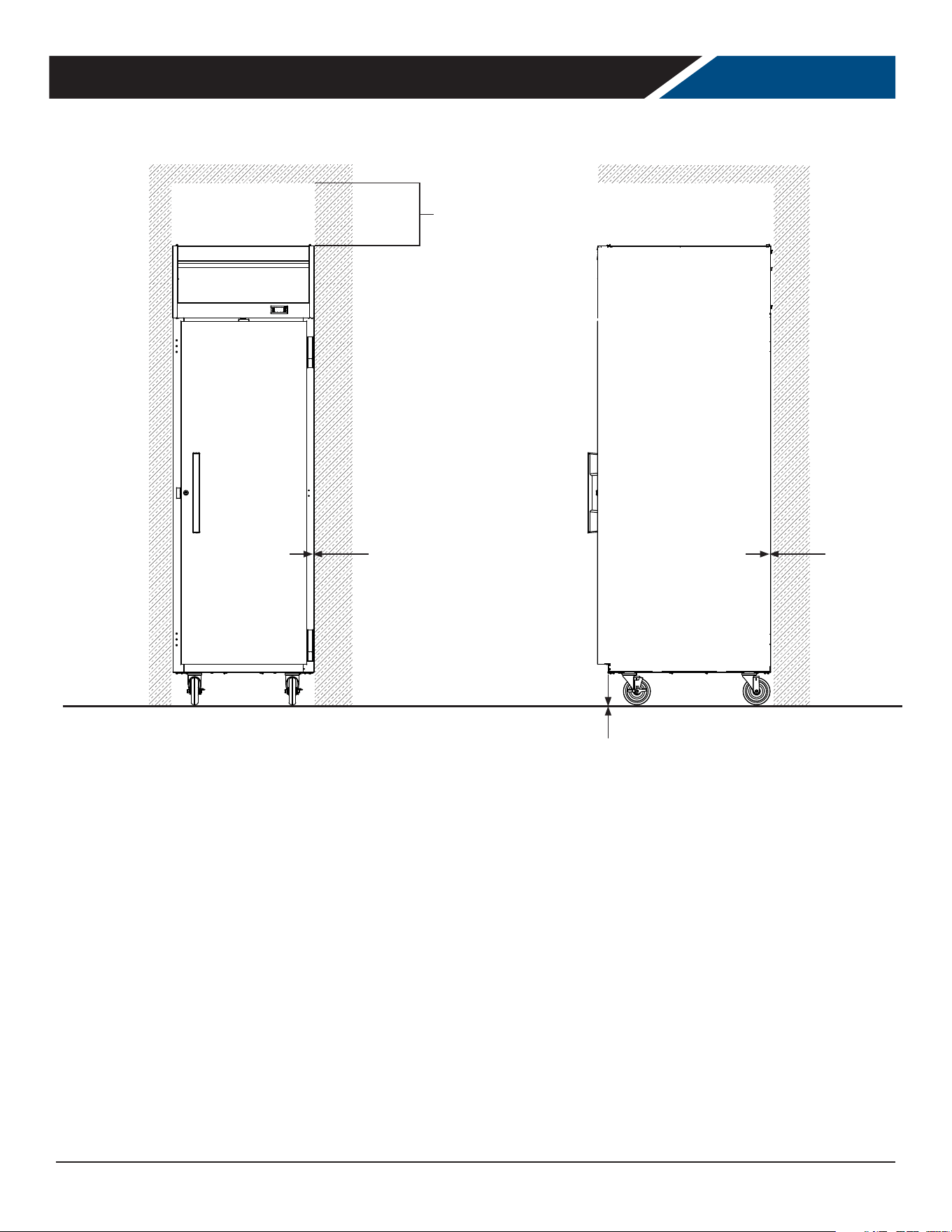
CLEARANCE AND PLACEMENT
Placement
Consider the following when selecting a location for your Cabinet:
Clearance:
• 12 in. at the top
• 0.0 in. at the rear
• 0.0 in. at the left side
• 0.0 in. at the right side
• 0.0 in at the bottom
Floor Load: the oor on which the Cabinet is located must be even and level, free from vibrations, and strong enough to
support the combined weights of the unit and maximum product load.
Ventilation: Grille area at front must be free and clear of any object or wall.
Power Outlet: The installation of this appliance requires a dedicated power outlet located within the length of the unit's
power cord and be accessible for the purpose to disconnect power.
12"
TOP
MINIMUM
CLEARANCE
REQUIRED
0"
BOTTOM
MINIMUM
CLEARANCE
0"
LEFT/RIGHT
MINIMUM
CLEARANCE
0"
REAR
MINIMUM
CLEARANCE
User Manual for HS and HIS Warming Cabinets Victory
Rev. 02/26Victory8
UNPACKING AND SET UP
Carefully inspect the shipping carton for damage. This is the only time that shipping damage may be claimed. If damage is
suspected, open the carton immediately and, if there is damage, retain the carton and contact the shipper to make a claim.
Do NOT contact the manufacturer.
Uncrating
Tools Needed: ¾” box wrench, adjustable wrench, level, at
head screw driver, and box cutter.
1. Remove the cardboard top capping, all clear tape,
and all staples including those at the bottom of the
cardboard carton and skid.
2. Start from the top of the carton. Using the box cutter,
carefully make one continuous cut to the bottom of the
skid. Remove cardboard carton and discard.
Note: additional clear plastic protective wrap is applied
directly to any product with a glass door.
3. Move unit as close to nal position as possible before
removing the skid.
Note: The skid must be removed before the casters or legs
can be attached.
Skid Removal and Caster Attachment
Tip the unit forward and remove the skid.
Risk of personal injury.
Unit must be securely supported
while attaching casters or legs.
WARNING
1. Remove the shipping bolts using the ¾” box wrench while
cabinet is held in one direction. Repeat the process while
the cabinet is held in the opposite direction.
2. None of the threads on the leg or caster stem should be
visible once screwed in.
3. Tilt the cabinet in one direction approximately 8” and
block it securely with pieces of 2x4 lumber or other
suitable material.
4. Thread the stem casters or legs into the ½ -13 holes in
the bottom of the cabinet. Tighten by hand as much
as possible. Some models may already have levelers
installed. If so, then the levelers will need to rst be
removed and discarded.
5. Once the caster or leg cannot be turned any further,
use a 3/4 inch wrench to tighten the nut in between
the mounting plate and the wheel of the caster until
snug.
6. Repeat this procedure with unit secured in the
opposite direction so as to access the remaining legs/
casters/levelers
7. If plate casters or legs are installed instead of stem
casters or legs, then repeat step 3 above and secure
the plate with either #14 AB screws, or ¼-20 screws,
depending upon which are required.
8. If levelers are employed, then repeat step 3 above and
thread the leveler in place. Then repeat step 6.
9. If legs/casters will not be installed, please see page 9.
Leveling:
Cabinets must be leveled when installed. Level should be
measured on the headrail.
Failure to level your cabinet may result in door not sealing,
closing correctly, voiding the warranty.
For cabinets with legs, rotate the foot of the leg with an
adjustable wrench to achieve desired height for leveling.
For cabinets with casters, leveling can be achieved by
placing large washers in between the ½’ stud and the holes
located on the bottom of the case.
Do NOT loosen casters to level
the cabinet. Casters MUST be
tightly secured to cabinet for full
strength.
Install or attach any accessories that will be used
Remove any plastic covering the stainless steel.
CAUTION

User Manual for HS and HIS Warming Cabinets Victory
Rev. 02/26 Victory 9
SET UP FOR UNITS WITHOUT LEGS/CASTERS
Important: The oor where the cabinet is to be
permanently located must be a level, at surface
prior to installation. Failure to properly level your
equipment can void equipment warranty.
• If legs or casters are not installed, this equipment is
required to be sealed to the oor to establish proper
sanitary operation. This is a requirement called out in
the NSF-4 standard and will be enforced by local health
inspectors.
• For warming cabinets mounted directly onto the oor,
the oor must be cleaned and dried in advance of the
application of sealant.
• Once the warming cabinet is installed onto a clean, dry
and level oor, the installation is to be completed by the
application of silicone.
The application of the silicone is to be done in a manner
to prevent spillage on adjacent surfaces of the oor from
passing under the inaccessible portions of the warming
cabinet.
INSTRUCTIONS:
1. Place the cabinet in the exact position in which it is to be
set permanently.
2. Level the unit, inserting metal shims under unit where
required. It is important that an accurate carpenter’s level
be used when leveling cabinet
3. Construct a wood form to act as a retainer for the
grouting compound around the entire base of the cabinet.
Pour the grout mixture at various intervals around the form
to assure complete ll under the cabinet
4. Using a wide blade putty knife, taper the grout to a
feather edge.
5. A tube of NSF approved silicone sealer, having an
applicator type nozzle, is highly suited for sealing units to
the oor. Apply a small uniform bead completely around
the base of the cabinet.
If necessary to move the unit after removing it from
the skid, remove all doors and carefully push the
cabinet at a point no more than 36” (inches) from the
bottom to avoid damage.
User Manual for HS and HIS Warming Cabinets Victory
Rev. 02/26Victory10
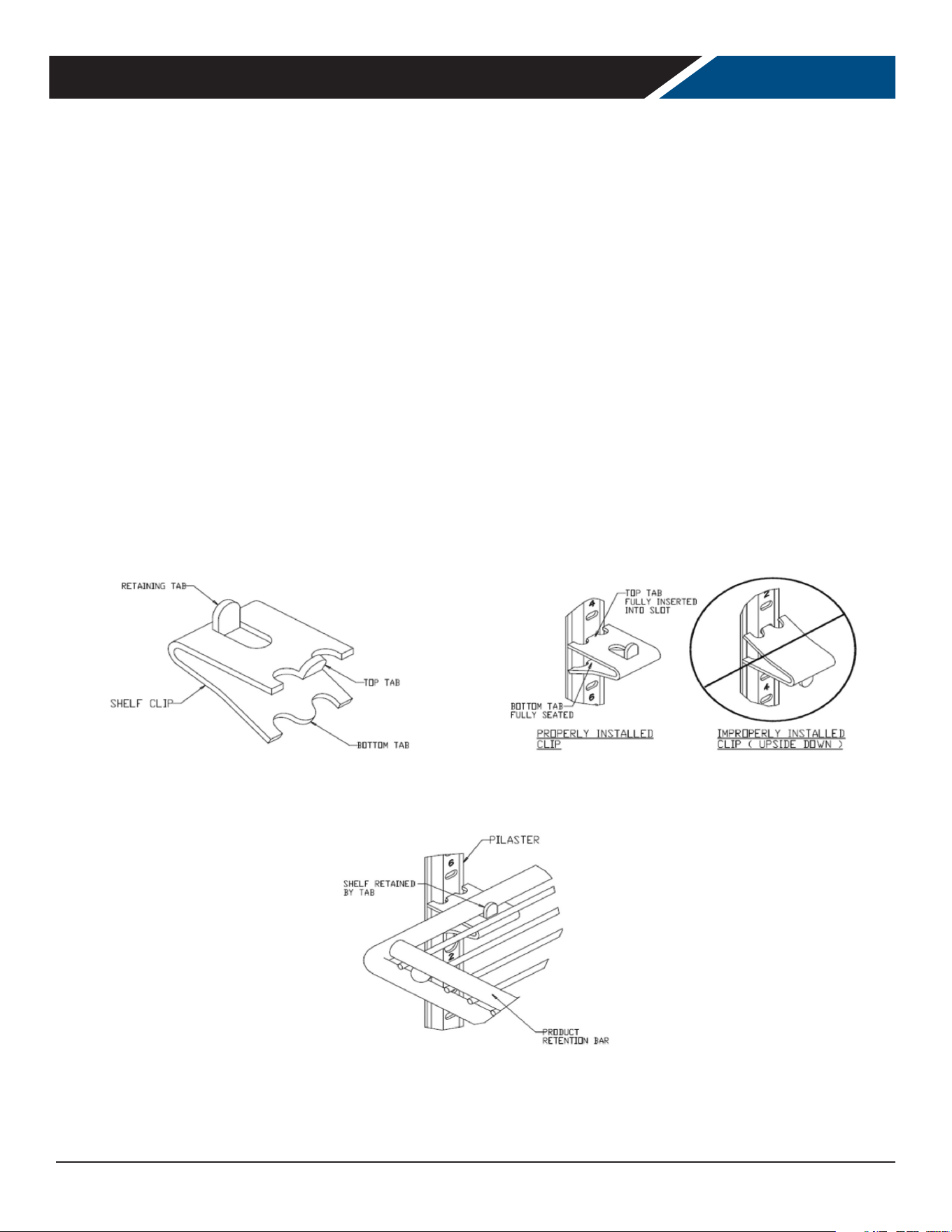
1. Determine the proper location for the shelf clips.
The reference numbers on the pilaster can serve as a
guide to ensure all clips are properly located.
2. Insert the top tab of the shelf clip into the desired
hole of the pilaster. The retaining tab MUST be facing
up as shown.
3. Rotate the clip downwards and insert the bottom tab
into the matching hole in the pilaster. The clip may
need to be squeezed slightly during installation.
4. Install all remaining clips.
5. Install shelves onto clips with the product retention
bar facing up. Be careful not to dislodge clips during
installation.
6. Place shelves so that the retaining tab on the clip
captures the shelf as shown.
7. Conrm that the shelf is resting on ALL 4 clips and
that the clips are securely attached to the pilasters.
8. Improper shelf clip installation could cause the shelf
and / or the product on it to fall, resulting in damage
to the unit and possible bodily injury.
9. Do NOT overload the shelves. The unit is designed to
use all shelves that are supplied in an equally spaced
manner. Contact Victory customer service if fewer
shelves or a dierent conguration to ensure shelf
overloading will not occur.
SHELF INSTALLATION

User Manual for HS and HIS Warming Cabinets Victory
Rev. 02/26 Victory 11
This is a cord-connected unit, and must be connected to
its own dedicated power supply. Check the dataplate on
the machine to conrm the voltage and per the dataplate
use the correct fuses or circuit breakers.
Note: Do not connect to GFI / GFCI outlets. Connection to that type of outlet can result in product loss due to unsafe
cabinet temperature when GFI device trips from moisture.
Power Cords
This 220 volt model is equipped with a power cord and type
6-20P plug.
If a power cord becomes damaged, it must be replaced
with the identical cord.
Follow All National and Local Codes
This Unit Must Be Grounded. Do not use extension cords
and do not disable or by-pass ground prong on electrical
plug.
Prior to use, the interior and exterior surfaces of the
cabinet should be cleaned thoroughly with warm water,
mild detergent, and a soft cloth. Apply with a dampened
cloth and wipe in the direction of the metal grain. Then
allow to air dry with the doors open. Only use a clean soft
cloth. See detailed cleaning instructions in the cleaning
and maintenance section
Initial Start Up
After the cabinet has been installed, leveled, and cleaned
as described above, refer to the following check list:
• Check for proper electrical hook-up.
• Check that all clearances are in line with the
aforementioned guidelines.
• Check that cabinet is level.
NOTE: Once the unit has been started and reaches proper
storage temperatures, it may be loaded with product.
ELECTRICAL
User Manual for HS and HIS Warming Cabinets Victory
Rev. 02/26Victory12
PREHEATING & FOOD STORAGE
Food should not be placed in a cold warming cabinet. To
preheat the warming cabinet, turn it on one (1) hour before
it will be needed. See page 14 on how to use the control
display panel to assist in preheating and operation.
If the food has been cooked in the same pan in which it
will be served, it should be left in the same pan when being
placed in the warming cabinet. However, if food is cooked
and served in dierent pans, the food should be panned as
soon as the cooking is completed and placed in the warmer.
Although the two methods mentioned may not necessarily
pertain to the requirements of daily foodservice activity,
another approach for good food quality is to place the food
directly to a serving counter after cooking. The warmer
keeps the food in good condition during the interval
between cooking and serving. It is recommended that food
should be stored within the cabinet and in its original pan in
which it will be served.
The food should be placed in the cabinet while hot, but not
until it stops giving o steam
Note: if steam is excessive, use a lid on pots or pans.
It is possible to reheat some food without further
deterioration if sucient time is allowed for the heat to
slowly penetrate the entire mass.
Most food can be kept in best condition at a temperature
of approximately 160°F, but the exact temperature varies
depending upon the kind of food and method of its
preparation; therefore, it is impossible to give any exact
instructions which will t all conditions. It is necessary to
experiment by increasing or decreasing the temperature
of the unit until you nd the temperature at which the
majority of the food kept in the unit will keep in the best
condition. Once this setting is determined, the controller
should always be kept at this setting.
Some food, such as breaded meats, sh, etc., when kept at
proper temperature, requires less degree of moisture in the
cabinet to prevent sogginess. For this reason, all cabinets
are equipped with vents or dampers. The damper should
be opened for such food by turning the knob in the desired
direction for opening and closing. This knob opens or
closes the vent in the top of the cabinet. By looking into the
cabinet when operating the knob, you can fully understand
its function and adjustment.
Some foods can be kept in good condition much longer than
others, and certain foods cannot be satisfactorily kept at
all in any manner. French fried potatoes, roasts, waes and
similar foods, where the outside must be crisp and centers
steaming hot must be prepared immediately before serving.
Do not expect the impossible from the warming cabinet, but
if used intelligently it will keep food over a longer period of
time and with less deterioration than is possible with any
other equipment. By reducing the deterioration between
the time the food is cooked and the time it is served,
the warming cabinet will assure serving the food to the
customer in proper condition. See the recommended food
storage periods table as a reference guide.
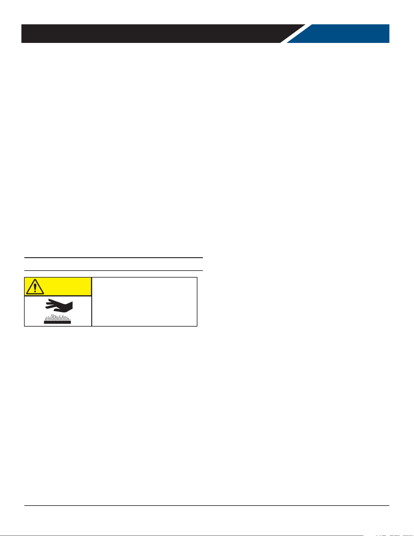
CAUTION
Risk of personal injury from hot
pans or racks.
User proper hot container handling
materials.
User Manual for HS and HIS Warming Cabinets Victory
Rev. 02/26 Victory 13
Product Longest Time Kept Average Time Kept Approximate Temp. °F
*Crispy or Dry Foods
Baked Potatoes 2 hours 30 minutes 170 -180
Corn Stick 2 hours 1 hour 140 - 150
Crackers 8 hours 5 hours 140 - 150
Chicken Pies 6 hours 3 hours 170 - 180
Club Sandwiches (wrapped) 1 hour 30 minutes 160
Fried Chicken 6 hours 3 hours 170 -180
Fried Seafood 6 hours 2 hours 170 -180
Hard Rolls 8 hours 4 hours 140 - 150
Hot Mince or Apple Pie 6 hours 4 hours 160
Meat Pies 6 hours 3 hours 170-180
Popcorn & Potato Chips 10 hours 5 hours 150
*Moist Foods
Baked Beans 8 hours 4 hours 170 -180
Baked Stu Lobster 3 hours 2 hours 170 -180
Biscuits 1 hour 30 minutes 150 - 175
Casserole (without top crust) 8 hours 4 hours 170 - 180
Chop Suey 6 hours 4 hours 180
Deviled Crabs 5 hours 3 hours 170 -180
Frankfurter 6 hours 3 hours 160 - 175
Hash 4 hours 2 hours 170 -180
Mashed Potatoes 3 hours 2 hours 160 - 180
Vegetables (ready for serving) 6 hours 2 hours 170 -180
Sweet Rolls 4 hours 2 hours 140 - 150
RECOMMENDED FOOD STORAGE PERIODS
User Manual for HS and HIS Warming Cabinets Victory
Rev. 02/26Victory14
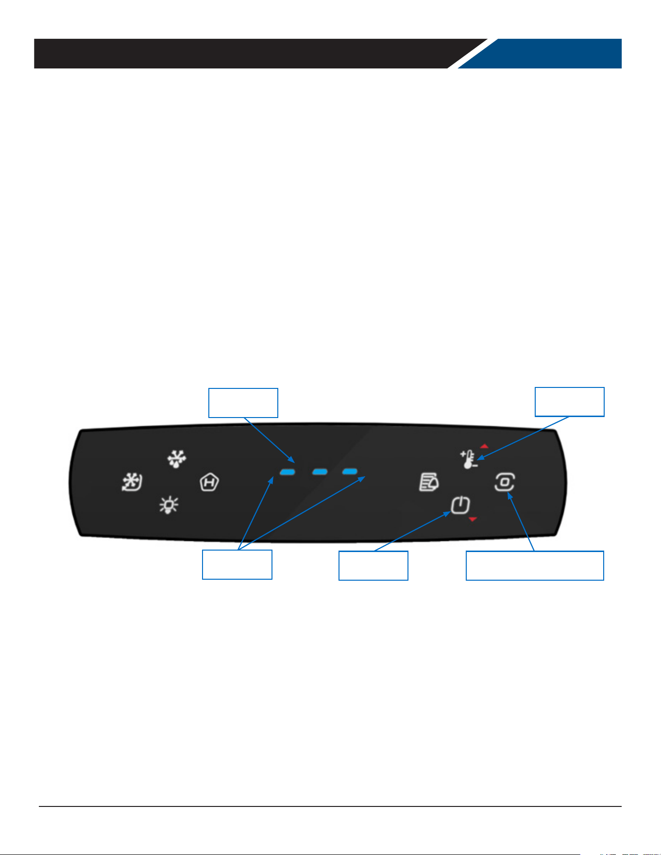
USING THE UNIT
Operation is simple, just keep it connected to the correct
power supply and the cabinet will maintain the internal
temperature it has been set to. Keep the doors closed as
much as possible to avoid unnecessary run time.
The controller displays the current internal temperature.
Adjusting the set temperature will NOT cause the system
to reach the temperature faster. When on, the system is
always operating at maximum.
The temperature was set at the factory at 160°F, but you
can adjust it to your own selected temperature. But you
can adjust them to your own selected temperature. See
pages 21 & 22.
The internal fan will be on when the compressor is on and
when the doors are closed.
The compressor and condenser fan motor will only be on
when the controller senses an increase in internal cabinet
temperature passed the set point.
Increase
Display
Icons
Decrease Changes begin with Parameter Button
User Manual for HS and HIS Warming Cabinets Victory
Rev. 02/26 Victory 15
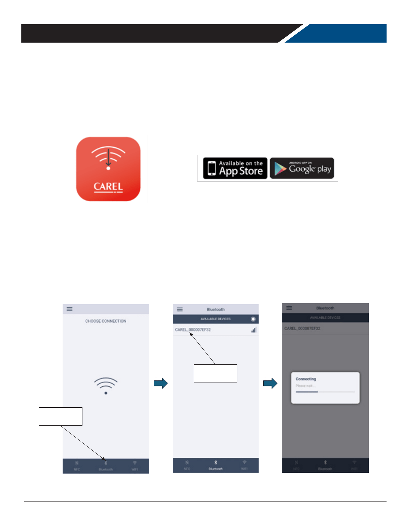
Open the app and select “Bluetooth” to search for your device. Select the Carel device that
appears on the screen and wait for the control to connect.
Bluetooth
Control
CAREL APPLICA APP
ACCESSING THE CONTROL VIA SMARTPHONE OR TABLET
Download the Carel APPLICA app through the App Store or Google Play Store to access
the control via Bluetooth.
User Manual for HS and HIS Warming Cabinets Victory
Rev. 02/26Victory16
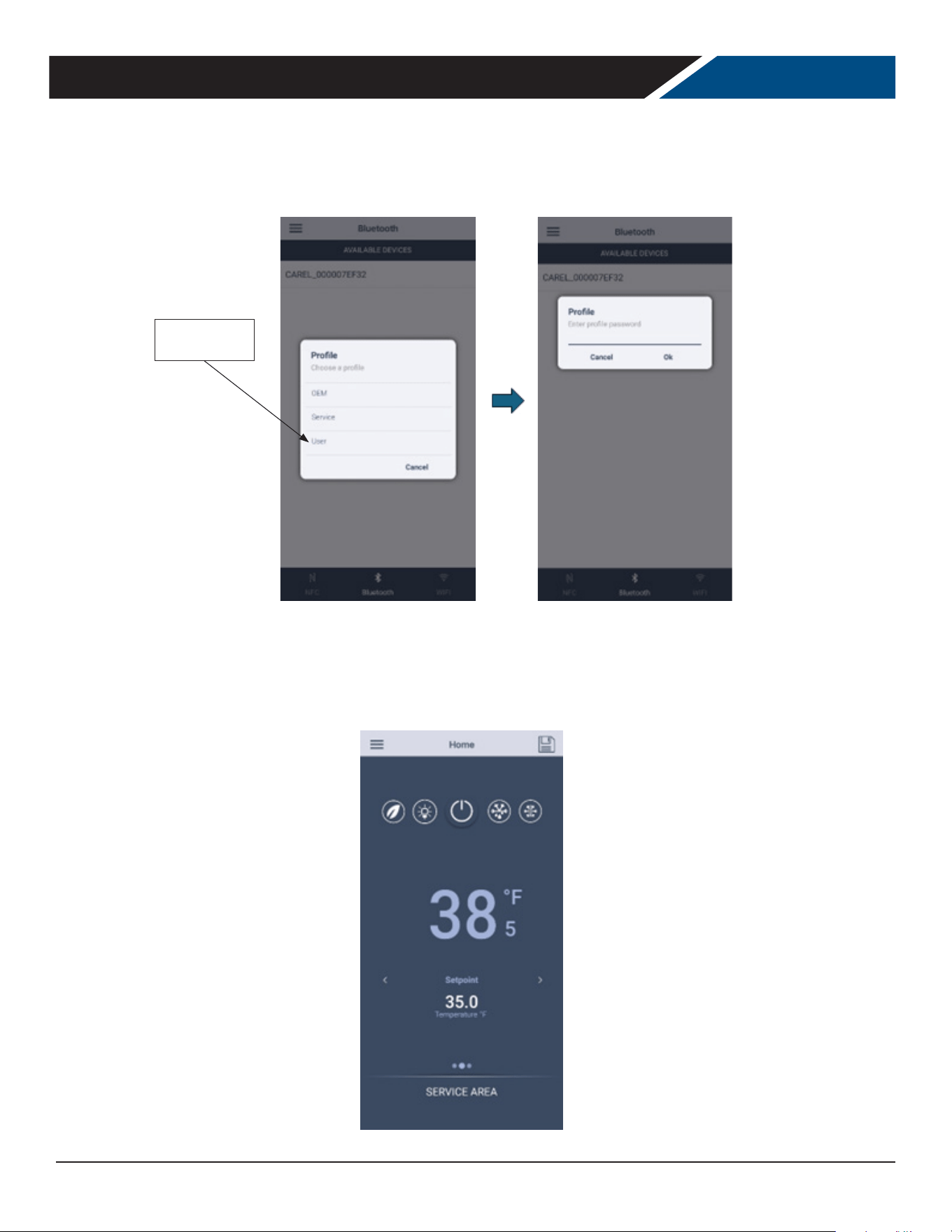
Arrive at the home page for the Applica App.
Select the “User” prole and type in the password: 0 and press “Ok”.
User
User Manual for HS and HIS Warming Cabinets Victory
Rev. 02/26 Victory 17
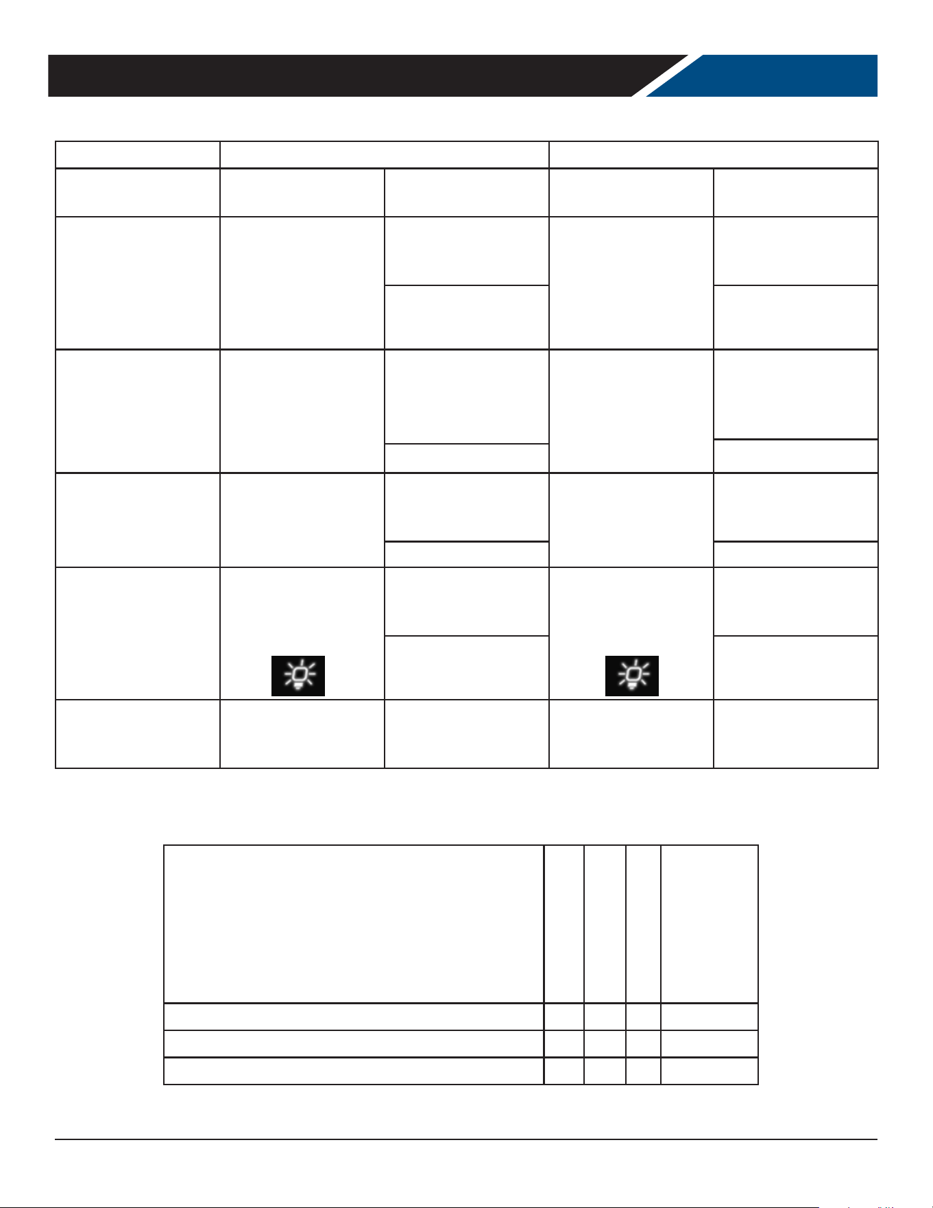
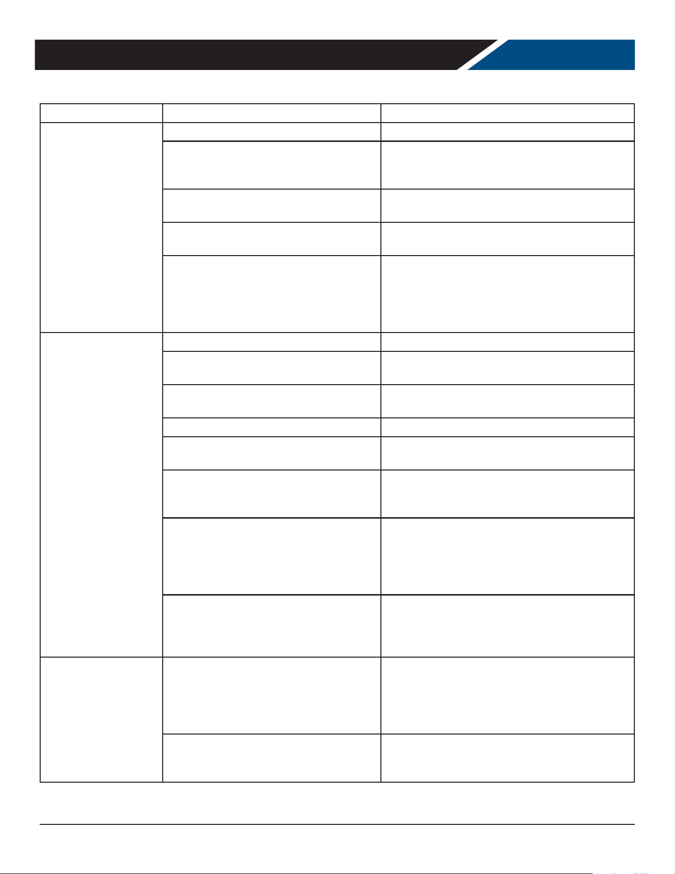
ON OFF
COMPONENT OPERATION CONTROLLER
ACTION
OPERATION CONTROLLER
ACTION
COMPRESSOR
Compressor turns
on when the cabinet
temperature is above
the sum of the set
point and the dead
band
The Compressor
Contact is energized
Compressor turns
o when the cabinet
temperature is equal
to or less than the set
point
The Compressor
Contact is de-
energized
IJF terminals NO5, C5 IJF terminals NO5, C5
CONDENSER FAN
The Condenser Fan
turns on when the
Compressor is running
The Condenser
Fan is wired to the
Compressor Relay on
control
The Condenser Fan
turns o when the
Compressor is not
running
The Condenser Fan is
wired directly to the
Compressor Control
Relay
IJF terminals NO5, C5
IJF terminals NO5, C5
EVAPORATOR FAN
The Evaporator Fan
runs continuously
except on door
opening.
The Evaporator Fan
Control contact is
energized.
The Evaporator Fan
turns o for 1 minute
when the door is
opened
The Evaporator Fan
Control contact is de-
energized
IJF terminals NO4, C3 IJF terminals NO4, C3
LIGHT
The light will turn on
when the door is open,
or the light button is
pressed
The Light Control
Contact is energized
The light will turn
o when the door is
closed, or the light
button is pressed
The Light Control
Contact is de-
energized
IJF terminals NO3, C3 IJF terminals NO3, C3
FACE HEATER
Face Heater is on
when condensing unit
is on
Heater is wired with
the compressor relay
The Face Heater is o
when condensing unit
is o
Heater is wired with
the compressor relay
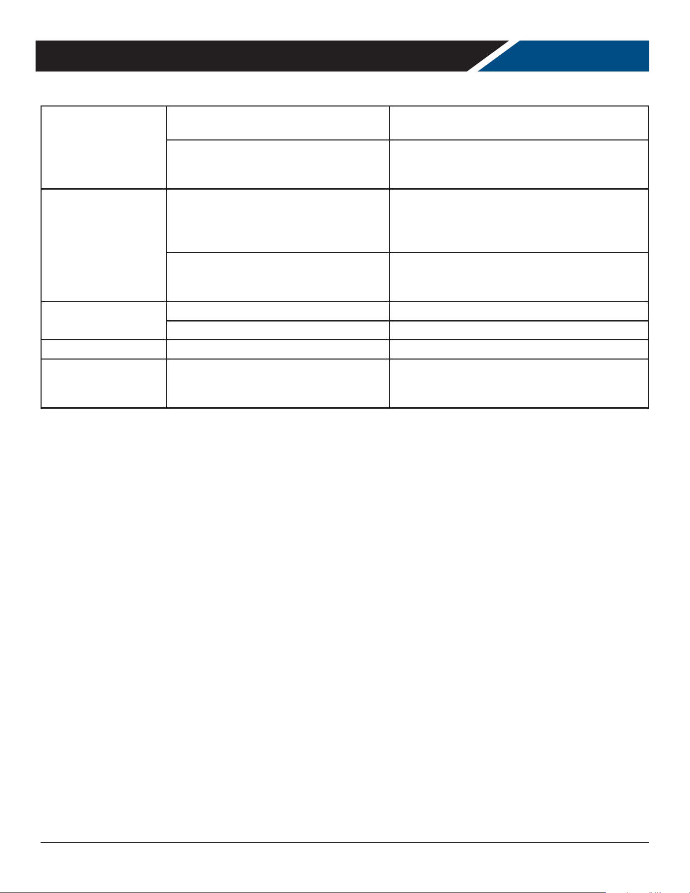
CONDITION
CABINET TEMP > SET POINT + DEAD BAND
ON ON ON ON or OFF
CABINET TEMPERATURE <= SET POINT
OFF OFF ON ON or OFF
DEFROST
OFF OFF ON ON or OFF
SEQUENCE OF OPERATIONS
COMPRESSOR
CONDENSER FAN
EVAPORATOR FAN
LIGHTS
User Manual for HS and HIS Warming Cabinets Victory
Rev. 02/26Victory18
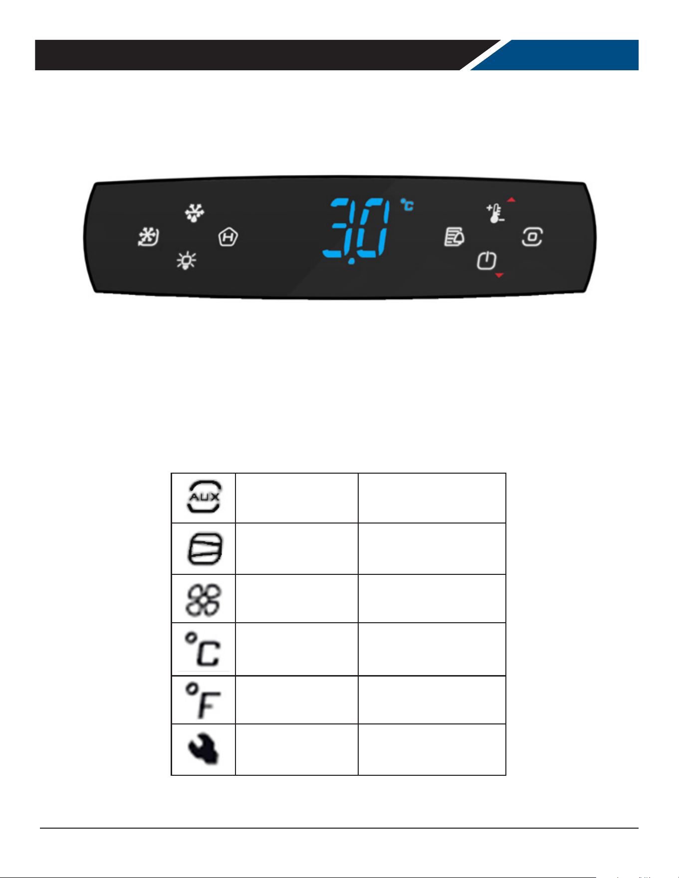
ELECTRONIC CONTROLLER DISPLAY
CONTROL PANEL INDICATORS
Auxiliary Output Active
Heater Active
Fans Active
°C Unit of Measure °C
°F Unit of Measure °F
Service Maintenance Active Alarms
User Manual for HS and HIS Warming Cabinets Victory
Rev. 02/26 Victory 19
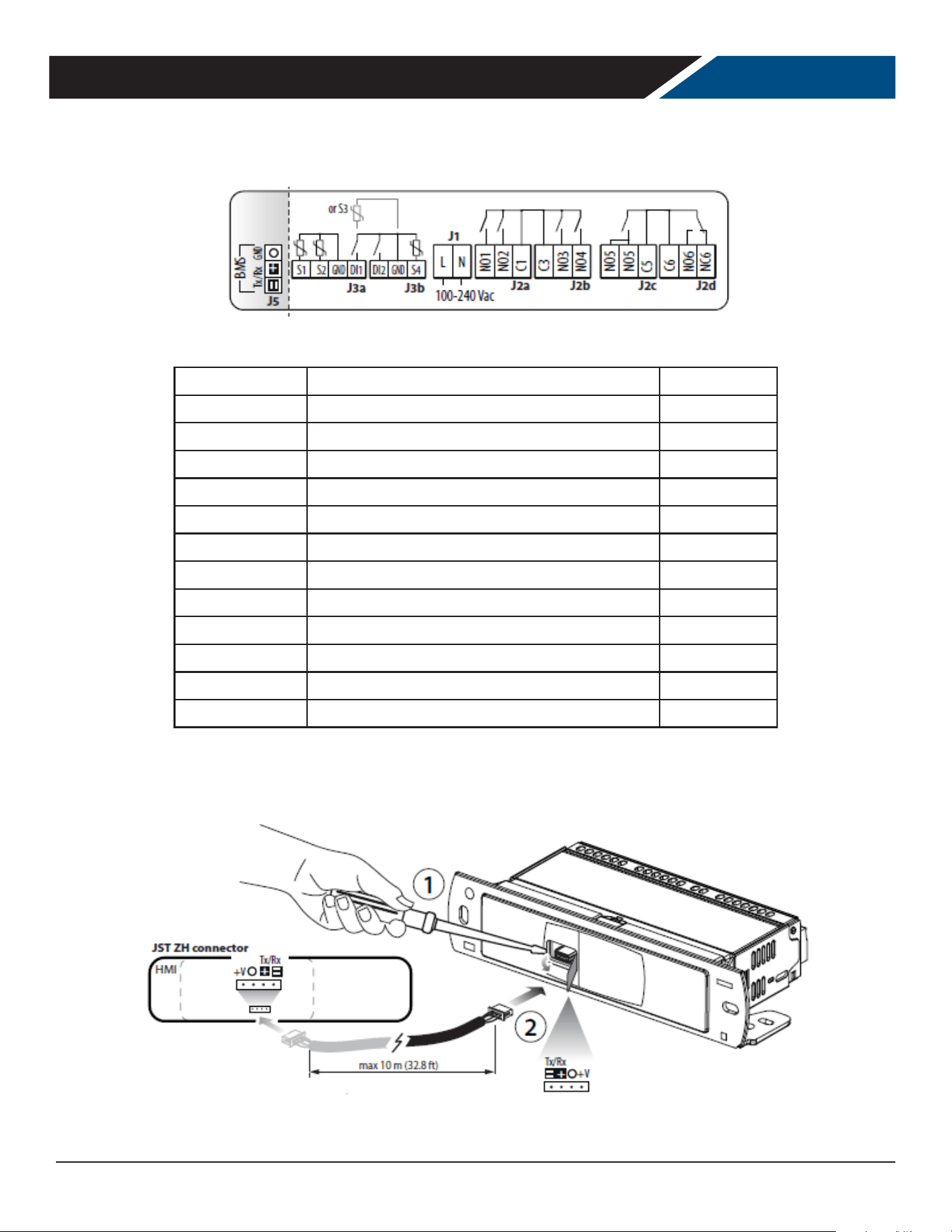
DISPLAY CONNECTION
Relay/Probe Description Terminal
NO1 NOT USED NO1, C1
NO2 NOT USED (EXTERNAL ALARM) NO2, C1
NO3 LIGHT NO3, C3
NO4 BLOWER NO4, C3
NO5 HEATER NO5, C5
NO6 DEFROST ELEMENT (NOT ACTIVE) NO6, C6
NC6 NOT USED NC6, C6
S1 AIR/CONTROL PROBE S1, GND
S2 EVAPORATOR/DEFROST PROBE 1 S2, GND
DI1 DIGITAL INPUT/DOOR SWITCH DI1, GND
DI2 NOT USED DI2, GND
S4 EVAPORATOR/DEFROST PROBE 2 S4, GND
CONTROL PANEL CONNECTIONS
User Manual for HS and HIS Warming Cabinets Victory
Rev. 02/26Victory20
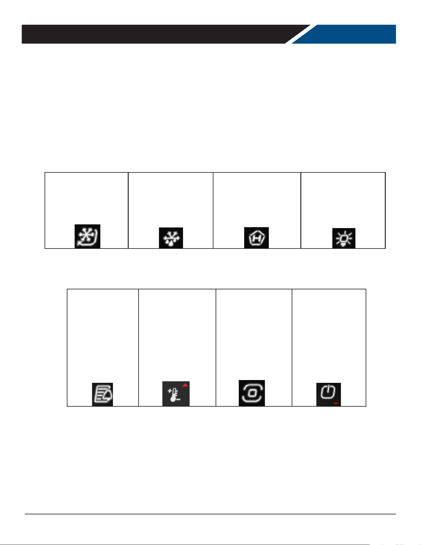
CONTINUOUS CYCLE
Press and Release
Activate/Stop
Continuous Cycle mode
DEFROST (NOT ACTIVE)
Press and Release
Activate/Stop Defrost
HACCP
Press and Release
View HACCP alarms and
HACCP menu
LIGHT
Press and Release
Toggle light on and o
ALARM LOG
Press and Release
View active alarms
and alarm menu
SET/ UP
Press and Release
Quickly access
setpoint adjustment.
Scrolls menus and
increases values
PROGRAM (ENTER)
Press and Release
Used as enter button.
Saves Parameter
Value
Press and Hold (3s)
Take the control out
of standby. Return to
previous parameter
POWER/ DOWN
Press and Release
Switch unit on and
o. Scrolls menus
and decreases
values
Note: Keypad has a 3 second lock feature. Press and hold the program button for 3 secs to
unlock. All icons will appear when keypad is unlocked
KEYBOARD FUNCTIONS
User Manual for HS and HIS Warming Cabinets Victory
Rev. 02/26 Victory 21
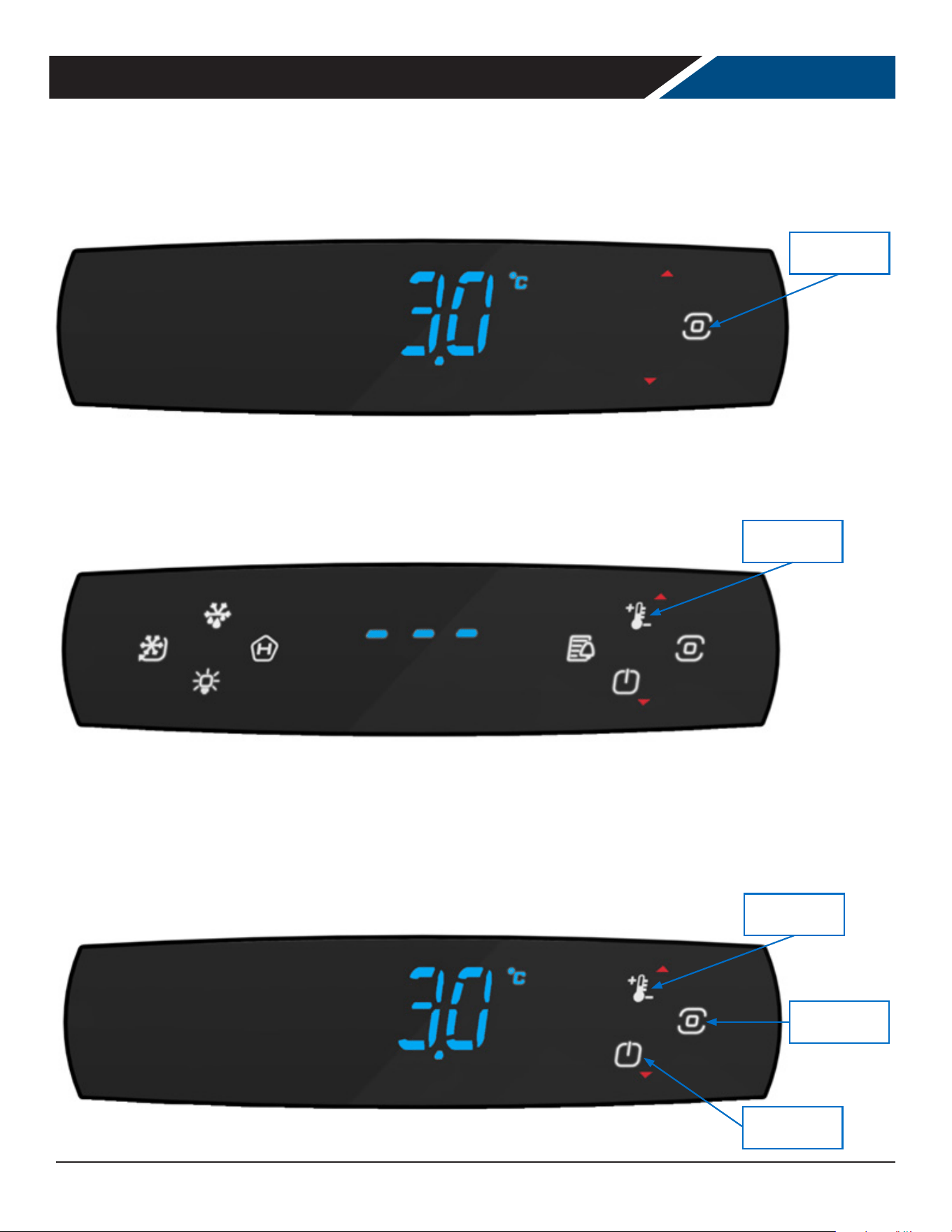
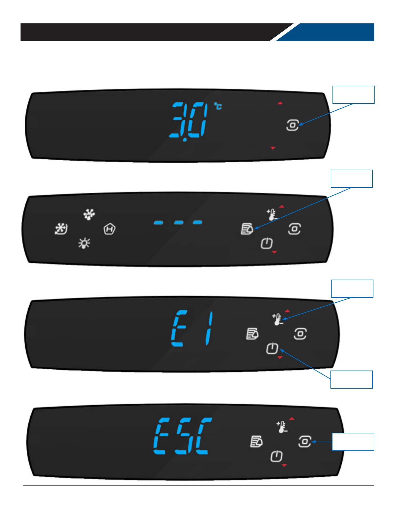
To change the operating set point, press and hold the parameter button for three seconds
until the other buttons appear.
Press and release the set button to view the setpoint.
Use the up and down button to change the setpoint. When adjustment is nished, press
and release the parameter button to save the change.
CHANGING THE OPERATING SETPOINT - CONTROL PANEL
Parameter Button
Set Button
Up Button
Enter Button
Down Button
User Manual for HS and HIS Warming Cabinets Victory
Rev. 02/26Victory22
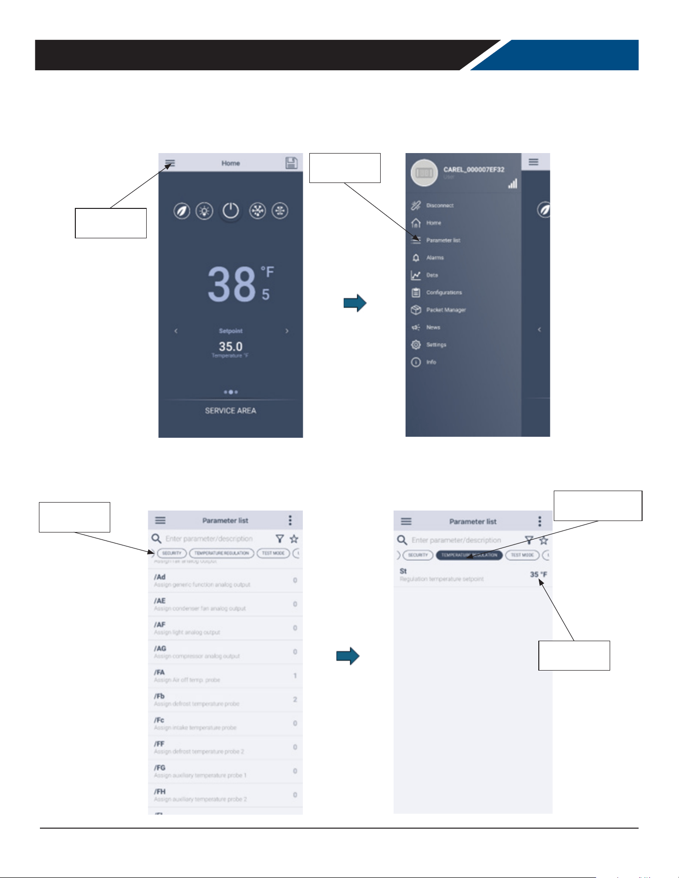
Open the menu and go to the parameter list.
Parameter List
Menu
Scroll across the parameter tags and nd the one labeled "Temperature Regulation". Select
it and change the Setpoint (St).
Parameter Tags
Setpoint
Temperature Regulation
CHANGING THE OPERATING SETPOINT - CAREL APPLICA APP
User Manual for HS and HIS Warming Cabinets Victory
Rev. 02/26 Victory 23
VIEWING ALARM CODES - CONTROL PANEL
To view the alarm codes, press and hold the parameter button for three seconds until the
other buttons appear.
Press and release the alarm log button to view the alarm codes.
Use the arrows to scroll through the alarm code.
Scroll to "ESC" and press the enter button to exit the alarm log.
Parameter Button
Alarm Log
Up Button
Down Button
Enter Button
User Manual for HS and HIS Warming Cabinets Victory
Rev. 02/26Victory24
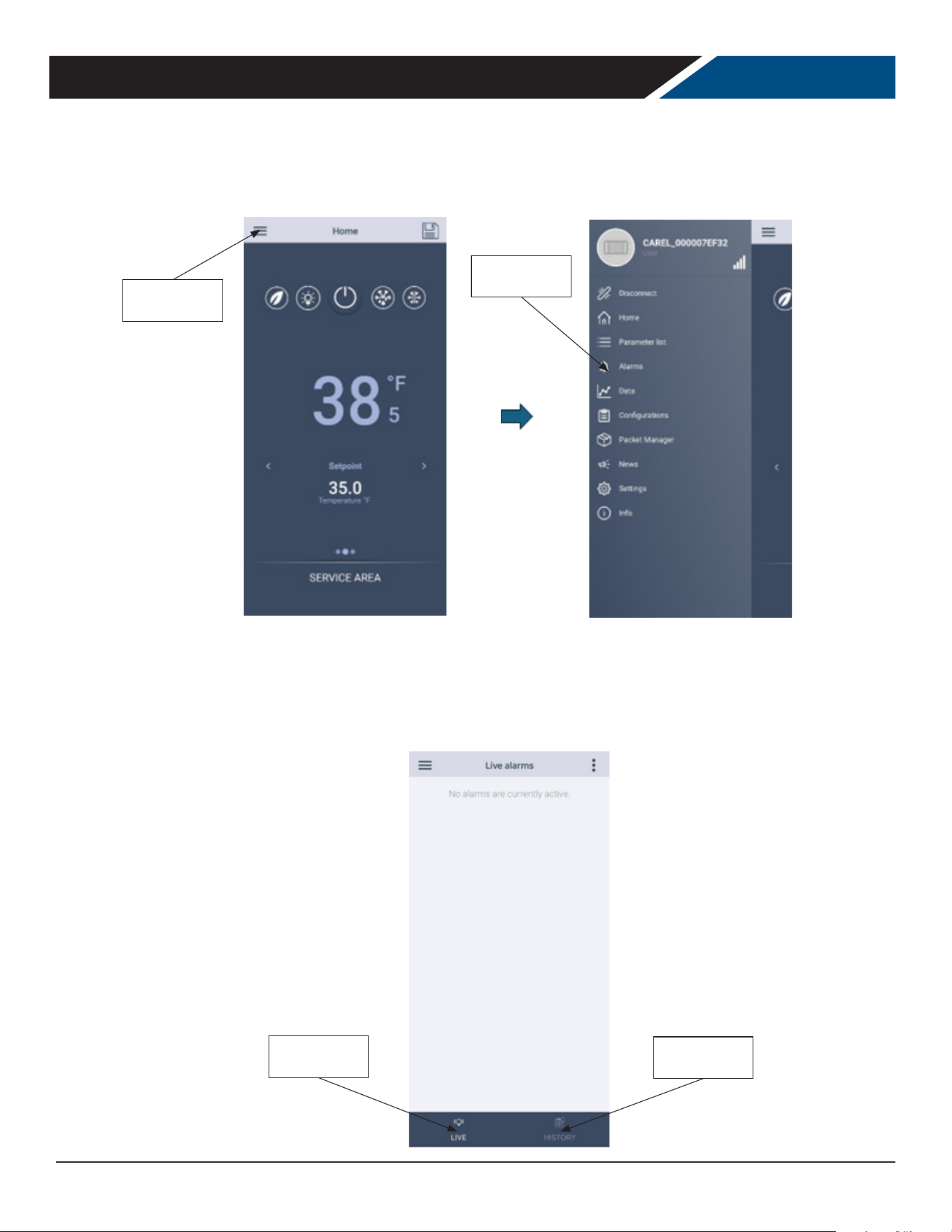
VIEWING ALARM CODES - CAREL APPLICA APP
Here you can view active alarm codes and a history of alarms that have gone o.
Live Alarms
Alarm History
Open the menu and open to the alarms page
Menu
Alarms
User Manual for HS and HIS Warming Cabinets Victory
Rev. 02/26 Victory 25
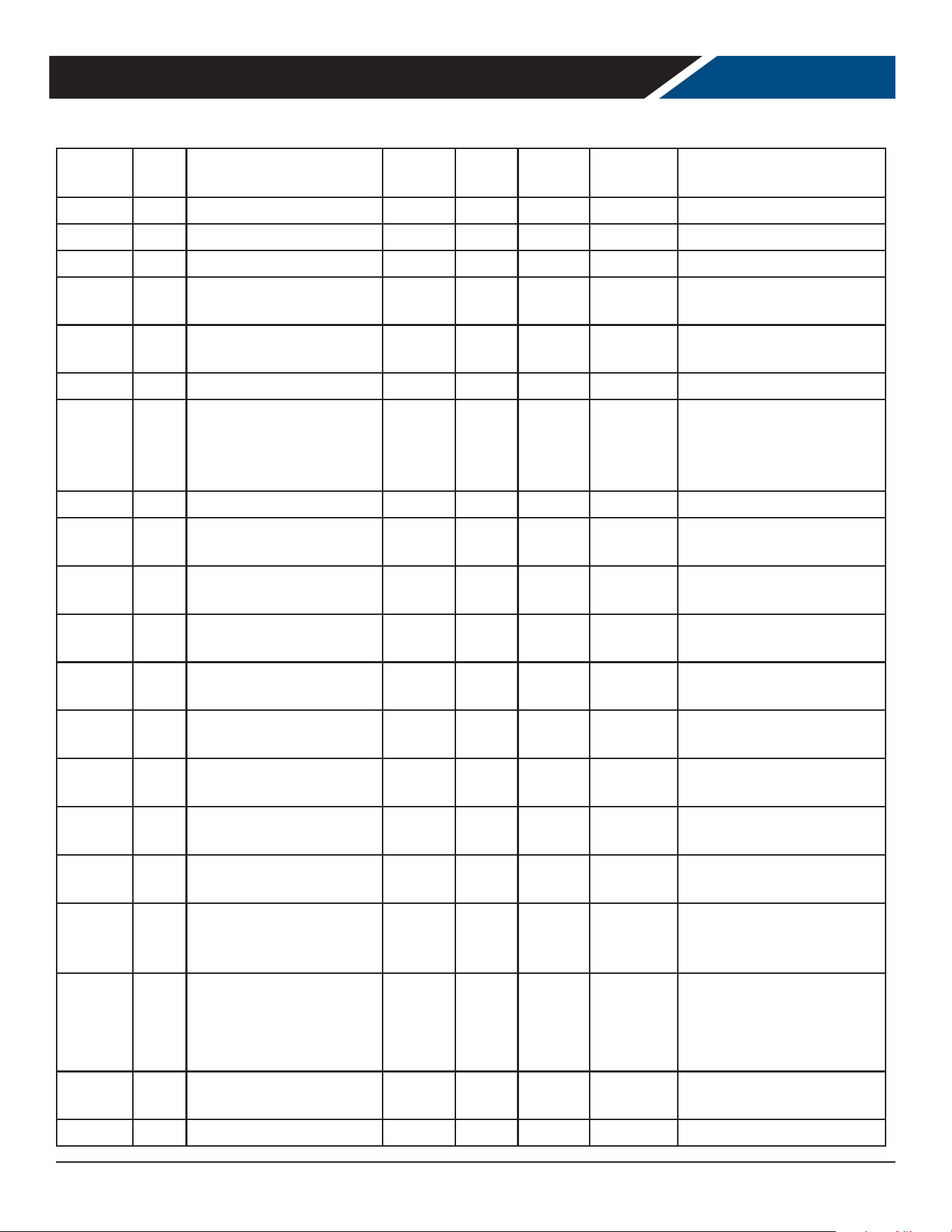
Display
Code
Log
Code
Description Icon
Display
Alarm
Relay
Buzzer Reset Eects on Control
Afr 29 Frost protection YES YES YES Automatic Compressor OFF
AtS 30 Restart in pump down NO NO NO Automatic
CE 28 Conguration write error NO NO NO Automatic
cht 17 High condensing
temperature warning
NO NO NO Automatic
CHt 18 High condensing
temperature alarm
NO NO NO Manual Compressor OFF
COM 34 VCC communication error YES YES YES Automatic
dA 14 Delayed alarm from
external contact
YES YES YES Automatic Compressor operation in
duty setting mode (par
A6); dead band, lights and
auxiliary output OFF
dor 15 Door open YES YES YES Automatic See “Door management”
E1 1 Probe 1 faulty or
disconnected
NO NO NO Automatic According to the associated
function (see below)
E2 2 Probe 2 faulty or
disconnected
NO NO NO Automatic
E3 3 Probe 3 faulty or
disconnected
NO NO NO Automatic
E4 4 Probe 4 faulty or
disconnected
NO NO NO Automatic
E5 5 Probe 5 faulty or
disconnected
NO NO NO Automatic
E6 6 Probe S1H faulty or
disconnected
NO NO NO Automatic
E7 7 Probe S2H faulty or
disconnected
NO NO NO Automatic
Ed1 10 Defrost terminated after
maximum time
NO NO NO Automatic
Ed2 11 Defrost on second
evaporator terminated
after maximum time
NO NO NO Automatic
EHI 36 High power supply voltage
alarm
YES YES YES Automatic
ELO 37 Low power supply voltage
alarm
YES YES YES Automatic
Etc 9 Clock Error NO NO NO Manual Time bands disabled
ALARM CODES
User Manual for HS and HIS Warming Cabinets Victory
Rev. 02/26Victory26
Display
Code
Log
Code
Description Icon
Display
Alarm
Relay
Buzzer Reset Eects on Control
GHI 19 Generic alarm high
threshold
YES YES YES Automatic
GLO 20 Generic alarm low threshold YES YES YES Automatic
HA 21 Type HA HACCP alarm (high
temp. during operation)
NO NO NO Manual
HF 22 Type HF HACCP alarm (high
temp. after blackout)
NO NO NO Manual
HI 24 High temperature YES YES YES Automatic
IA 13 Immediate alarm from
external contact
YES YES YES Automatic Compressor operation in duty
setting mode (par A6); dead
band OFF
LO 23 Low temperature YES YES YES Automatic
LP 32 Low pressure YES YES YES Semi-
automatic
Compressor OFF
MAn 38 Output status overridden in
manual mode
YES YES YES Automatic
Pd 26 Maximum pump down time YES YES YES Automatic
rE 12 Control probe faulty or
disconnected
YES YES YES Automatic Compressor operation in duty
setting mode (par c4); dead
band OFF
rSF 31 Refrigerant leak alarm YES YES YES Manual Switch o all actuators
SF 27 Conguration not completed
correctly
NO NO NO Manual
SrC 35 Maintenance request YES YES YES Manual
UCF 33 VCC operation error YES YES YES Automatic
ALARM CODES CONT'D

User Manual for HS and HIS Warming Cabinets Victory
Rev. 02/26 Victory 27
CLEANING AND MAINTENANCE
Cleaning Schedule:
Cabinet
Daily wipe down
Weekly interior
Gaskets
Daily inspection, check
that hinges are tight to
the cabinet.
Routine maintenance
Annually
Daily Exterior Cleaning
It is much easier to clean on a regular basis than to have
to remove stains once they have built up.
1. Wash with a clean sponge and a mild detergent that
does not contain chlorine.
2. Rinse with clean water.
3. Dry with a soft cloth.
4. Polish with a soft cloth, wiping with the grain.
5. Wipe weekly with stainless steel cleaner.
Weekly Interior Cleaning
1. Remove all food, food related items and shelves. Store
the food at a safe temperature.
2. Disconnect power to the unit (unplug it or switch the
breaker o).
3. Remove all loose food particles from the inside walls,
oor, door liner and ceiling.
4. Scrub all interior surfaces and door gaskets with a
warm (100
o
F to 110
o
F) detergent solution and a soft
scrub brush.
5. Rinse with clean water and allow to air dry.
6. Return the shelves to the unit and secure them.
7. Restore power.
8. Return food to the unit when it has reached a safe
temperature.
Periodic, Gaskets
1. Visually inspect the door gaskets for a tight seal on all four sides. Inspect for any type of damage such as rips, tears,
stiness, or cracks.
2. If any such condition exists, the magnet will not seal and the gasket will need replaced.
3. Cleaning the gasket requires the use of mild dish detergent and warm water. Next, thoroughly rinse and dry the
gasket.

User Manual for HS and HIS Warming Cabinets Victory
Rev. 02/26Victory28
Cleaning Needed Cleaning Agent Method of Application Aect on Finish
Smears and ngerprints
Areal 20, Lac-O-Nu, Lumin Wash
O’Cedar Cream Polish, Stainless
Shine.
Rub with cloth as directed
on the package.
Satisfactory for use on all
nishes.
Provides barrier lm to
minimize prints.
Stubborn Spots and
Stains, Baked-On
Splatter, and Other
Light Discolorations
Allchem Concentrated Cleaner.
Apply with damp sponge or
cloth.
Rub with damp cloth.
Use in direction of polish lines
on No. 4 (polished) nish. May
scratch No.
2 (mill) and Nos. 7 and 8
(polished) nishes.
Samae, Twinkle or Cameo Copper
Cleaner
Rub with damp cloth.
Grade FFF Italian pumice, whiting,
or talc.
Rub with dry cloth.
Liquid NuSteel
Paste NuSteel or DuBois Temp.
Copper’s Stainless Steel Cleaner
Revere Stainless Cleaner
Household cleansers, such as
Old Dutch, Lighthouse, Sunbrite,
Wyandotte, Bab-O, Gold Dust,
Sapolio, Bon Ami, Ajax, or Comet
Grade F Italian Pumice, Steel
Bright, Lumin Cleaner, Zud,
Restore, Sta-Clean, or Highlite.
Penny-Brite or Copper-Brite.
Use small amount of cleaner.
Rub with dry cloth using a
small amount of cleaner.
Apply with damp sponge or
cloth.
Rub with a damp cloth. May
contain chlorine bleaches.
Rinse
thoroughly after use.
Rub with a damp cloth.
Rub with a dry cloth using a
small amount of cleaner.
Heat tint or
discoloration
Penny-Brite or Copper-Brite.
Past NuSteel, DuBois Temp,
or Tarnite. Revere Stainless Steel
Cleaner. Allen Polish, Steel Bright,
Tenacious Deposits,
Rusty Discolorations,
Industrial
Atmospheric Stains Wyandotte,
Bab-O or Zud.
Rub with a dry cloth.
Rub with a dry cloth or stain-
less steel wool.
Apply with damp sponge or
cloth.
Rub with a damp cloth.
Burnt-On Foods and
Grease Fatty Acids,
Milkstone (where
swabbing or rubbing
is not practical)
Easy-O, De-Grease-It, 4 to 6%
hot solution of such agents as
trisodium phosphate or sodium
tripolyphosphate or 5 to 15% caustic
soda solution
Apply generous coating. Allow
to stand for 10-15 minutes.
Rinse.
Repeated application may be
necessary.
Excellent removal, satisfactory
for use on all nishes.
Tenacious Deposits,
Rusty Discolorations,
Industrial
Atmospheric Stains
Oakite No. 33, Dilac Texo 12, Texo NY,
Flash-Klenz, Caddy Cleaner,
Turco Scale 4368 or Permag 57.
Swab and soak with clean
cloth.
Let stand 15 minutes or more
according to directions on
package, then rinse and dry.
Satisfactory for use on all
nishes
Hard Water Spots
and Scale
Vinegar.
5% oxalic acid, 5% sulfamic acid, 5 to
10% phosphoric acid, or Dilac, Oakite
No. 33, Texo 12, Texo N.Y.
Swab or wipe with cloth. Rinse
with water and dry.
Swab or soak with cloth. Let
stand 10-15 minutes. Always
follow with neutralizer rinse,
and dry.
Satisfactory for all nishes.
Satisfactory for all nishes.
Eective on tenacious deposits
or where scale
has built up.
METHODS FOR CLEANING STAINLESS STEEL
User Manual for HS and HIS Warming Cabinets Victory
Rev. 02/26 Victory 29
HELP
PROBLEM POSSIBLE CAUSE REMEDY
Cabinet not operating Fuse blown or circuit breaker tripped Replace fuse or reset circuit breaker
Power cord unplugged Plug in power cord to designated receptacle.
Cabinet cannot share same outlet with other
equipment.
Improper voltage supplied to cabinet
(voltage does not match Data-Plate).
Correct supply voltage (remove extension cords or
other equipment on circuit, etc)
Main power switch and/or controller
turned o
Turn on main power switch and/or controller.
Defective high limit/heater safety switch Internal high limit/heater safety may be defective.
Contact the factory or an authorized service
provider for further assistance if all else has
been checked above and the cabinet is still not
operating.
Cabinet not holding
temperature
Cabinet not pre-heated before use Turn cabinet on one (1) hour before use
Prolonged door opening of door ajar Make sure door is closed when not in use. Avoid
prolonged door openings.
Door gasket not sealing properly Check door gasket condition Adjust door or
replace gasket.
Controller setpoint is too low Adjust controller setpoint to a higher temperature
Improper voltage supplied to cabinet
(voltage match Data-Plate )
Correct supply voltage (remove extension cords or
does not) other equipment on circuit, etc).
Product load held too long Hold product load inside cabinet per
recommended temperature. Examples of holding
times and temperatures are on page 11.
Blower motor not operating or air duct is
air duct is restricted,
Check blower motor and air duct for proper air
ow. Try to carefully locate and remove the cause
of air restriction. If further assistance is restricted
required, contact the factory or authorized service
provider for further assistance.
Heater elements not operating Carefully check heater elements for proper
operation .If heating element(s) are not working
properly, contact the factory or an authorized
service provider for further assistance.
Cabinet is overheating. Defective high limit/heater safety switch If controller setpoint is adjusted to a lower setting
and the internal cabinet temperature exceeds
+200' F, turn o cabinet and contact the factory
or an authorized service provider for further
assistance
Defective blower motor Check blower motor operation. If blower motor
is not operating, contact the factory or an
authorized service provider.
User Manual for HS and HIS Warming Cabinets Victory
Rev. 02/26Victory30
Product load burning
or boiling
Product load is too close to heating
element
Rearrange product load so that it is not too close
to heating element(s).
Controller setpoint is too high Adjust controller setpoint to a lower setting.
Examples of holding times and temperatures are
within the operator's manual.
Product load becoming
soggy
Too much humidity or moisture inside
cabinet
Adjust or close internal venting/damper knob to
control moisture. Normally the internal venting/
damper should be open for products such as
breaded meats, sh, etc
Product load held too long time. Hold product load inside cabinet per
recommended time. Examples of holding times
and temperatures are on page 11.
Cabinet is noisy Part(s) loose Locate and tighten loose part(s)
Cabinet is not level Level cabinet by adjusting legs or shimming caster
Door won't close Hinge(s) may need slight adjustment Apply shim(s) to hinge until door seals properly
Controller Alarm &
Error
---- Refer to either pages 15 or 19 of manual for alarm
codes. If problem( s) persist, contact the factory
for further assistance
HELP CONTINUED
User Manual for HS and HIS Warming Cabinets Victory
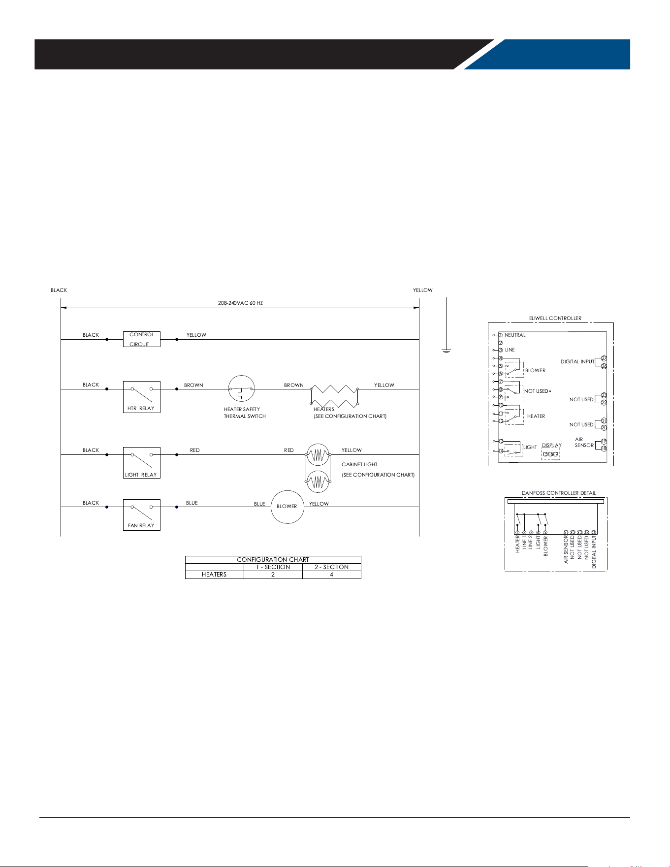
Rev. 02/26 Victory 31
FOR THE SERVICE TECH - WIRING DIAGRAM
01234
567723
86961ÿ965
86197ÿ38
81ÿÿ16795
86961
66ÿ241924ÿ891
01234
567723
567723
079
9046ÿ78
66ÿ241924ÿ891
16
78ÿÿ16795
567723
076
072361
94ÿ16795
24127
1
567723
9ÿÿ8
079
079
079
079
076
16
42ÿ6
42ÿ6
91ÿ
6421
78
072361
97ÿ4
46197
746
86961
!
"
673677ÿ24127761
#
$
"
""
"
"!
"
" ""#
795
"
"$
"
#
!
42ÿ6
42ÿ6
42ÿ6
072361
42ÿ6
91ÿ6421
78
97ÿ4
!"
746ÿ
746ÿ"
86961
942ÿ24127761ÿ697
!"
241924ÿ891ÿ823ÿ823ÿ945ÿ22464ÿ916ÿ6ÿ4ÿ9ÿ"ÿÿ624ÿ94ÿÿÿ624ÿ39161%ÿ
22464ÿ916ÿ316ÿ4ÿ91677ÿ76ÿ4ÿ86ÿ919ÿ9026%
&&&&&&&&&&&&&&&&&&&&&&&ÿÿ()*ÿ+,ÿ-(.ÿ&&&&&&&&&&&&&&&&&&&&&&&
9
497ÿ167696ÿ21ÿ1224
/$/
00
95
6$
-(.
-(.121+)ÿ-(3+-*
*45(
67
389
(3):ÿ)+:
241924ÿ891
"ÿÿ624 ÿÿ624
86961
9046ÿ78
"
072361
""
0
9
9
0
"
!
#
#
!
"
497ÿ6461;
<=>?@ABACDA=ECAF?=@G%>@H
16
866ÿ"ÿ2ÿ"
976;ÿ";"
86ÿ421924ÿ24946ÿ4ÿ8
1934ÿÿ86ÿ276ÿ12615ÿ2
06619691ÿ2121924%ÿÿ945ÿ
161224ÿ4ÿ91ÿ21ÿ9ÿ9ÿÿ
38276ÿ382ÿ86ÿ3164ÿ
6124ÿ2ÿ06619691ÿ
2121924ÿÿ12806%
"
IC<CAFECF=A%>@H
0122776Jÿ9
3424976Jÿ4
81ÿ9476ÿ120624
KLMNOPOQ
314ÿ919ÿÿ9ÿ
39161
9
476ÿ286136ÿ66;
3%ÿÿ42%
6
6
76;
6446614
16R1664;
6424ÿ916ÿ4ÿ486
2761946;
94791;ÿÿ
ÿÿ
ÿ
246ÿ796ÿ697ÿÿ
ÿ%
32ÿ796ÿ697ÿÿ
ÿ%!
8166ÿ796ÿ697ÿ
ÿ%"
S-+S-1(54-7ÿ4)*ÿ3+),1*()514T

User Manual for HS and HIS Warming Cabinets Victory
Rev. 02/26Victory32
LIMITED WARRANTY
Warranty (Continental USA & Canada Only)
SEVEN (7) YEAR PARTS, LABOR, AND COMPRESSOR
LIMITED WARRANTY
Victory® Refrigeration (Victory) warrants to the
original purchaser of Victory branded equipment,
that such equipment is free from defects in material
and workmanship, under normal use, proper
maintenance and service as indicated by Victory’s
installation and operation instructions, for a period
of SEVEN (7) years from the date of installation, or
eighty-seven (87) months from the date of shipment
from the manufacturer, whichever is earlier. In
addition, Victory® Refrigeration (Victory) warrants the
hermetically/semi-hermetically sealed compressor
(part only) for SEVEN (7) years; not to exceed eighty-
seven (87) months from the date of shipment from
Victory, provided upon receipt of the compressor,
manufacturer examination shows the sealed
compressor to be defective. This warranty does not
cover freight for the replacement compressor or
freight for return of the failed compressor. Also, this
compressor-part only warranty does NOT apply to
any electrical controls, condenser, evaporator, fan
motors, overload switch, starting relay, capacitors,
temperature control, lter/drier, accumulator,
refrigeration tubing, wiring harness, labor charges, or
supplies which are covered by the standard warranty
above.
*Units shipped after 07/1/2024. Previous warranty
applies to units shipped prior.
Exceptions:
• Warranty does not apply for units installed
in a Residential application. Units are intended for
Commercial use only.
• Blast Chillers carry a 3 year parts and labor
warranty; 2 additional years for the compressor.
Normal wear type parts, such as light bulbs/lamps,
gaskets, fuses, batteries, blast chiller/freeze probes,
thermostat or electronic controller calibration and/
or adjustment, and any normal maintenance items as
outlined in the Owner’s Manual, adjustment of door
mechanisms or freight damage are not covered by this
warranty. For this warranty, the original purchaser
shall be deemed to mean the individual or company for
whom the product was originally installed.
Proof of purchase must be supplied to Victory to
validate the warranty. This warranty is valid only
if equipment is properly installed, and started-up as
outlined in the Owner’s Manual.
Units that utilize variable speed compressor
technology can experience nuisance tripping on Class
A GFCI outlets which have a trip limit of 4 mA to 6
mA. To avoid this issue in a location that requires GFCI
circuit protection, Beverage Air & Victory recommends
using a HUBBELL Model Number GFRST83W 20A
Heavy Duty Hospital Grade Self-Test GFCI Receptacle.
Removal or alteration of the serial/ data plate from
equipment shall be deemed to release Victory from
all warranty obligations or any other obligations,
expressed or implied . The warranty does not cover
installation, start-up, normal maintenance, food
loss, or other consequential damage, and it excludes
components that are removable without tools. Our
obligation under this warranty shall be limited to
repairing or replacing, including labor, any part of such
product, which proves defective.
Victory reserves the right to examine any product
claimed to be defective. The labor warranty shall be
for self-contained units only and for standard straight
time, which is dened as normal service rate time,
for service performed during normal working hours.
Any service requested outside of a servicer’s normal
working hours will be covered under this warranty
at the normal rate and any additional overtime rate
will be the responsibility of the equipment purchaser.
Victory shall not be responsible for any costs incurred
if the work is performed by other than Victory’s
authorized service personnel. Reimbursement claims
for parts and/or labor service costs must be made in
writing. Model, cabinet serial number and installation
location must be shown on the claim. A receipted bill
from the servicing agency must accompany the claim,
together with full details of the service problems,
diagnosis and work performed. Victory reserves
sole discretion whether further documentation on a
claim is to be submitted. Any part determined to be
defective in the product should be returned to the
company within thirty (30) days under the terms of
this warranty and must be accompanied by a record
of the cabinet model, serial number, with a return
material authorization number (RMA#) issued by
Victory.

User Manual for HS and HIS Warming Cabinets Victory
Rev. 02/26 Victory 33
LIMITED WARRANTY (CONTINUED)
Special installation/applications, including remote
locations, are limited in coverage by this warranty.
Any installation that requires extra work, and/
or travel, to gain access to the unit for service is
the sole responsibility of the equipment purchaser.
Improper operation resulting from factors, including
but not limited to, improper or negligent cleaning
and maintenance, low voltage conditions, inadequate
wiring, outdoor use and accidental damage are
not manufacturing defects and are strictly the
responsibility of the purchaser.
Except Blast Chillers, a product is designed for
maintaining temperature and not bringing food to a
desired temperature, so cannot be held responsible for
this function under warranty.
Units must be in conditioned environments or
warranty will be void.
Condenser coils must be cleaned at regular intervals.
Failure to do so can cause compressor malfunction and
will void warranty. Although cleaning requirements
vary in accordance with the operation of various
products, Victory recommends a minimum monthly
cleaning.
NOTE: NO CLAIMS CAN BE MADE AGAINST THESE
WARRANTIES FOR SPOILAGE OF PRODUCTS,
LOSS OF SALES OR CONSEQUENTIAL DAMAGES.
THE FOREGOING WARRANTIES ARE EXPRESSLY
GIVEN IN LIEU OF ALL OTHER WARRANTIES,
EXPRESS, IMPLIED, OR STATUTORY, INCLUDING
THE IMPLIED WARRANTIES OF MERCHANTABILITY
AND FITNESS FOR A PARTICULAR PURPOSE,
WHICH ARE HEREBY DISCLAIMED, AND ALL OTHER
OBLIGATIONS OR LIABILITIES ON OUR PART, AND
WE NEITHER ASSUME, NOR AUTHORIZE ANY OTHER
PERSON TO ASSUME FOR US, ANY OBLIGATION OR
LIABILITY IN CONNECTION WITH THE SALE OF SAID
REFRIGERATION UNITS OR ANY PARTS THEREOF.
These warranties shall not be assignable and shall be
honored only in so far as the original purchaser.
These warranties do not apply outside the limits of
the USA and Canada, nor do they apply to any part
that has been subject to misuse, neglect, alteration,
accident, or to any damage caused by transportation,
ood, re, acts of terrorism, or acts of God.
LIMITATION OF LIABILITY:
Victory or its aliates shall not be liable for any
indirect, incidental, special or consequential
damages, or losses of a commercial nature arising
out of malfunctioning equipment or its parts or
components thereof, because of defects in material or
workmanship. In no event shall Victory be liable for a
sum more than the purchase price of the item.
THE ORIGINAL OWNER’S SOLE AND EXCLUSIVE
REMEDY AND VICTORY’S SOLE AND EXCLUSIVE
LIABILITY SHALL BE LIMITED TO THE REPAIR
OR REPLACEMENT OF PARTS OR COMPONENTS
CONTAINED IN THE EQUIPMENT IDENTIFIED
ABOVE WHICH UNDER NORMAL USE AND SERVICE
MALFUNCTION AS A RESULT OF DEFECTS IN
MATERIAL OR WORKMANSHIP, SUBJECT TO THE
APPLICABLE PROVISIONS AND LIMITATIONS STATED
ABOVE. 07/2024
User Manual for HS and HIS Warming Cabinets Victory
Rev. 02/26
Warranty Registration
Register your product online at victoryrefrigeration.com/parts-service or ll out and mail the form below.
Cabinet Model Number: _____________________________________________ Date Of Installation: _________________
Cabinet Serial Number: _____________________________________________
Location Of Product
Business Name: ____________________________________________________
Business Street: ____________________________________________________
Business City: ____________________________________ State: _________ Postal Code:___________
Mail to: Victory, 3779 Champion Blvd, Winston-Salem, NC 27105