IDS Geo
MNG/2025/012 Rev. 1.0 June 2026 User Manual
ORIGINAL INSTRUCTION IN ENGLISH LANGUAGE
MyMo
User Manual

MyMo – Ver. 001 – User Manual Mod: MDM/011/M2 Rev11
IDS GeoRadar Srl MNG/2025/012 Rev. 1.0 2/ 71
LEGAL NOTICE
Use of the Manual
This Manual is intended to be used solely by authorized user of IDS GeoRadar Systems. It is specific for internal business purpose only. If you are not an authorized user, you are NOT allowed to
read this Manual and you must return it to IDS GeoRadar as soon as possible. Access to and use of this Manual is also provided subject to the acceptance of the Disclaimer set out below.
Disclaimer
About the Manual
This Manual has been drafted by IDS GeoRadar with the due care in order to ensure the accuracy and completeness. However, please note that no warranty is provided about the fact that the
Manual will be free from error or omission and about the accuracy and/or fitness to the purpose of any information contained herein.
Any representation and/or statement contained herein has been written in good faith and on the basis that, due to negligence, lack of care or otherwise, IDS GeoRadar is not liable for any loss,
including direct, indirect or consequential losses, in contract or in tort for any misstatement or omission contained herein which has occurred or may occur with reference to any representation
and/or statement contained in the Manual.
User shall also acknowledge that some information contained in the Manual may not be up to date. IDS GeoRadar may amend the information contained in the Manual from time to time and IDS
GeoRadar shall not be deemed liable in the event that damages arise with reference to changed circumstances or other information which may affect the accuracy of any information contained in
this version of the Manual.
About the Product
All products designed, produced and distributed by IDS GeoRadar, its Subsidiaries, Affiliated and authorized Distributors (Products) shall not be used, in the design, development, production or use
of chemical, biological, nuclear ballistic weapons. Buyer/ User will defend, indemnify and hold IDS GeoRadar harmless against any liability (including attorney’s fees) for non-compliance with the
terms of this paragraph.
If IDS GeoRadar requires that Buyer/User shall carry out a training with reference to some Product categories, no operation or use of the Products shall be started before its designated Operator/s
has got the User Certificate, as defined by IDS GeoRadar specific procedure which the Buyer confirms to know and accept.
For Products which include specific “Operational” software with automatic data processing and analysis “Tools”, e.g. RockSpot, IBIS Products; MyMo, User shall be aware that the results provided
by these “Tools” may be not error free. User that completely relies on the outcomes provided by these Tools only, does it at his own risk.
In no event IDS GeoRadar shall be liable for special, direct, indirect, incidental, exemplary, punitive or consequential damages including, but not limited to, loss of profits or revenue, caused by the
missed or incomplete observance of the instructions and prescriptions for the use of the Products, either separately or in combination with other products.
This paragraph provides only a non-exhaustive summary of the full Product disclaimer. Please see the full Product disclaimer included into the relevant section of this Manual for detailed information.
Confidentiality
This Manual may be subject to legal and other privilege. IDS GeoRadar specifically reserves its rights in relation to this Manual. None of these rights or any other rights subsisting in the Manual are
waived if you have received this Manual in error or without permission. No parts of this Manual may be copied, translated or reduced to any electronic medium, or machine-readable form, nor
photographed or recorded in any way, without the prior written consent of IDS GeoRadar.

INDEX Mod: MDM/011/M2 Rev10
IDS GeoRadar Srl MNG/2025/012 Rev. 1.0 3/ 71
INDEX
1. INTRODUCTION .......................................................................................................................................................................................................................................... 6
1.1 ESTIMATED READING TIME .................................................................................................................................................................................................................................. 6
1.2 PURPOSE .......................................................................................................................................................................................................................................................... 6
1.3 APPLICATION FIELD ............................................................................................................................................................................................................................................. 6
1.4 INTENDED READERSHIP ........................................................................................................................................................................................................................................ 6
1.5 AUTHORIZATION OF USE ...................................................................................................................................................................................................................................... 6
1.5.1 CE Compliance ...................................................................................................................................................................................................................................... 6
1.5.2 Japan Compliance ................................................................................................................................................................................................................................. 7
1.5.3 FCC Compliance .................................................................................................................................................................................................................................... 7
2. HOW TO READ THE MANUAL ..................................................................................................................................................................................................................... 8
2.1 MANUAL LAYOUT ............................................................................................................................................................................................................................................... 8
2.2 SYMBOLS ....................................................................................................................................................................................................................................................... 8
2.3 GLOSSARY & ACRONYMS ..................................................................................................................................................................................................................................... 9
3. SAFETY DIRECTIONS ..................................................................................................................................................................................................................................10
3.1 INTENDED USE ................................................................................................................................................................................................................................................. 10
3.2 REASONABLY FORESEEABLE MISUSE ..................................................................................................................................................................................................................... 10
3.3 LIMITS OF USE ................................................................................................................................................................................................................................................. 11
3.4 RESPONSIBILITIES ............................................................................................................................................................................................................................................. 11
3.5 HAZARD OF USE ............................................................................................................................................................................................................................................... 12
4. CYBERSECURITY .........................................................................................................................................................................................................................................15
4.1 MYMO INTERFACES .......................................................................................................................................................................................................................................... 15
4.1.1 Physical interfaces .............................................................................................................................................................................................................................. 15
4.1.2 Network interfaces and supported protocols ..................................................................................................................................................................................... 15
4.2 SOFTWARE UPDATES AND CYBERSECURITY ............................................................................................................................................................................................................. 15
4.3 DURATION OF SAFETY SUPPORT .......................................................................................................................................................................................................................... 15
4.4 DATA PROTECTION AND SAFE COMMUNICATIONS .................................................................................................................................................................................................. 16
4.5 SUGGESTED SETTINGS FOR SAFE USE ..................................................................................................................................................................................................................... 16
4.6 HANDLING VULNERABILITY AND INCIDENTS ............................................................................................................................................................................................................ 16
4.7 LIMITATIONS AND SAFETY WARNINGS ................................................................................................................................................................................................................... 16
5. GENERAL DESCRIPTION .............................................................................................................................................................................................................................17

INDEX Mod: MDM/011/M2 Rev10
IDS GeoRadar Srl MNG/2025/012 Rev. 1.0 4/ 71
5.1 MYMO SYSTEM BASE ....................................................................................................................................................................................................................................... 17
5.2 MYMO BASE ACCESSORIES ................................................................................................................................................................................................................................ 17
5.3 MYMO FIELD APP ............................................................................................................................................................................................................................................ 19
5.4 MYMO SENSOR DESCRIPTION ............................................................................................................................................................................................................................ 19
6. HOW TO SET UP MYMO AND ACCESSORIES ..............................................................................................................................................................................................21
6.1 HOW TO SET UP MYMO ON TRIPOD .................................................................................................................................................................................................................... 21
6.2 HOW TO SET UP MYMO ON FIXED MOUNT KIT ...................................................................................................................................................................................................... 26
6.2.1 How to prepare the MyMo Fixed Mount Kit ....................................................................................................................................................................................... 27
6.2.2 How to install the Power supply on the Fixed Mount Kit .................................................................................................................................................................... 29
6.2.3 How to install MyMo Fixed Mount Kit on Horizontal Plan ................................................................................................................................................................. 31
6.2.4 How to install MyMo Fixed Mount Kit on a vertical structure ............................................................................................................................................................ 32
6.2.5 How to install MyMo Fixed Mount Kit on a vertical Pole ................................................................................................................................................................... 33
7. HOW TO GET STARTED MYMO FIELD APP .................................................................................................................................................................................................36
7.1 HOW TO GET STARTED MYMO FIELD APP (USING WIFI CONNECTION)........................................................................................................................................................................ 36
7.2 HOW TO GET STARTED MYMO FIELD APP (USING LAN CABLE CONNECTION) ............................................................................................................................................................... 42
8. HOW TO WORK ON SITE WITH MYMO ......................................................................................................................................................................................................43
8.1 HOW TO…PERFORM A VIBRATION AND DISPLACEMENT ANALYSIS (DYNAMIC MODE) ...................................................................................................................................................... 44
8.2 HOW TO…PERFORM A DISPLACEMENT ANALYSIS (STATIC MODE) ............................................................................................................................................................................... 50
8.3 HOW TO…PERFORM SLOPE MONITORING (STATIC MODE) ......................................................................................................................................................................................... 51
8.4 HOW TO…CUSTOMIZE THE VIEW OF A MONITORING SESSION .................................................................................................................................................................................... 52
8.4.1 How to change the main view (Graph or Map) .................................................................................................................................................................................. 52
8.4.2 How to select the point(s) to be displayed on Graph .......................................................................................................................................................................... 53
8.4.3 How to visualize the Resonant frequency (ONLY for DYNAMIC MODE) of specific point(s) ............................................................................................................... 53
8.4.4 How to add an event .......................................................................................................................................................................................................................... 53
8.4.5 How to switch the graph view from Displacement to Velocity ........................................................................................................................................................... 54
8.4.6 How to change Axis settings ............................................................................................................................................................................................................... 54
8.4.7 How to export data ............................................................................................................................................................................................................................. 54
8.4.8 How to change data view in Real Time .............................................................................................................................................................................................. 55
8.4.9 How to change Radar Point Cloud view based on SNR ....................................................................................................................................................................... 55
8.4.10 How to open a Monitoring Session ..................................................................................................................................................................................................... 56
8.4.11 How to download Logs ....................................................................................................................................................................................................................... 57
8.4.12 How to change settings ...................................................................................................................................................................................................................... 57
8.5 HOW TO…READ MYMO LED COLOR CODING ........................................................................................................................................................................................................ 60
8.5.1 Battery and Power Supply LED ........................................................................................................................................................................................................... 60

INDEX Mod: MDM/011/M2 Rev10
IDS GeoRadar Srl MNG/2025/012 Rev. 1.0 5/ 71
8.5.2 Hotspot and Internet connection LED ................................................................................................................................................................................................. 61
8.5.3 Camera/photo LED ............................................................................................................................................................................................................................. 61
9. CARE AND TRANSPORT .............................................................................................................................................................................................................................62
9.1 CLEANING INFORMATION ................................................................................................................................................................................................................................... 62
9.2 BATTERY REMOVAL INFORMATION ...................................................................................................................................................................................................................... 62
9.3 PERIODICAL CHECK ........................................................................................................................................................................................................................................... 63
9.4 PROPER SYSTEM USE ......................................................................................................................................................................................................................................... 63
10. IDS GEORADAR SUPPORT ......................................................................................................................................................................................................................64
10.1 MYWORLD ...................................................................................................................................................................................................................................................... 64
10.2 HOW TO MANAGE RETURN FOR SERVICE ............................................................................................................................................................................................................... 64
APPENDIX A DISCLAIMER .........................................................................................................................................................................................................................66
APPENDIX B TECHNICAL SPECIFICATIONS .................................................................................................................................................................................................70
APPENDIX C CONTACTS ............................................................................................................................................................................................................................71
1 INTRODUCTION Mod: MDM/011/M2 Rev 10
IDS GeoRadar Srl MNG/2025/012 Rev. 1.0 6/ 71
1. INTRODUCTION
This document describes MyMo system, that is a Ground Interferometric
Radar system by IDS GeoRadar.
It refers to the concepts the User must learn before initiating the utilization
of the device. Therefore, it is mandatory to carefully read the entire
document before starting and operating the system.
1.1 Estimated Reading Time
The estimated reading time of the entire document is 120 minutes.
1.2 Purpose
The purpose of this document is to guide the Reader to a list of actions to
install and use the MyMo system in a thorough, correct, and safe way.
The structure of the manual is organized in a collection of "how-to" as well
as “descriptive chapters”. Each chapter contains illustrations and basic
descriptions of the main operations to be carried out for system installation
and use on field.
1.3 Application field
The main application of MyMo is the collection of Interferometric data over
areas of variable extension, and for applications including, but not limited to:
Structural safety of buildings, bridges, towers, dams and manmade
structures in general (known as SHM, Structural Heal Monitoring),
Vibration analysis,
Displacement analysis
Slope stability
Open Pits
In general, any type of natural or manmade “scenario” that should be
studied, under static or dynamic conditions, in terms of its own relative
displacement or resonant frequency and that is placed at a maximum
distance from MyMo sensor up to 400 meters, based on system’s
specification and set up.
1.4 Intended readership
The intended Reader(s) of this manual is(are) the technician(s) in charge of
using the system that has undergone the IDS GeoRadar training for MyMo.
Training to Users, may also be delivered by either IDS GeoRadar local Selling
Units or Distributor Partners.
1.5 Authorization of use
The use of MyMo system may be subject to a license and/or authorization
by the Competent Ministry of the country where the system will be used.
1.5.1 CE Compliance
MyMo complies with the essential requirements of the
following directives and regulations:
Radio Equipment Directive (RED) 2014/53/EU
RoHS Directive 2011/65/EU and 2015/863/UE
REACH Regulation (EC) No 1907/2006
The full EU Declaration of Conformity (DoC) is available either
on the CD or a separate document included with this product.
This equipment is compliant with EN IEC 62368-1:2024.
Using MyMo is prohibited in specific areas of some European countries due
to exclusion zones around RAS observatories with free line of sight. Detailed
information on exclusion zones is available in ECC Decision (21)02.
1 INTRODUCTION Mod: MDM/011/M2 Rev 10
IDS GeoRadar Srl MNG/2025/012 Rev. 1.0 7/ 71
A list of approved countries for MyMo use is indicated in the REC 70-03,
Annex A. If the country does not allow MyMo use, contact the local
competent ministry or radio regulator to obtain permission to operate.
1.5.2 Japan Compliance
This device has been granted in accordance with the provisions of Article
38-24, Paragraph 1 of the Japan Radio Law.it can be considered a mmW
radar.
1.5.3 FCC Compliance
This device has been approved for operation under an FCC waiver of Part 90
of the FCC rules. Operation is subject to the specific conditions outlined in
the waiver grant DA-18-839A1. As stated in the waiver, MyMo must not,
under any circumstances, be operated while illuminating any public
roadway. Furthermore, as required in the same waiver, for MyMo:
The use is limited to underground mines, open-pit mines, and
tunnels;
The value of EIRP is below 48 dBm;
The device does not cause interference to, and accepts interference
from, Government Radiolocation, 76–81 GHz Band Radar, Radio
Astronomy, Amateur, and Space Research operations.
This equipment complies with FCC and IC radiation exposure limits set forth
for an uncontrolled environment. This equipment should be installed and
operated with a minimum distance of 30 cm between the radiator and your
body.
This transmitter must not be co-located or operated in conjunction with any
other antenna or transmitter.
Operation of this equipment is subject to the requirement to
obtain a site license from the FCC before being put into service. The license
application must be submitted at FCC Universal Licensing System.
This device also complies with part 15 of the FCC Rules. Operation is subject
to the following two conditions:
1. This device may not cause harmful interference, and
2. This device must accept any interference received,
including interference that may cause undesired
operation.
Changes or modifications not expressly approved by the manufacturer
could void the user’s authority to operate the equipment.
While the commercial name of the product is MyMo, the FCC ID is UFW-
HYDRA2.
2 HOW TO READ THE MANUAL Mod: MDM/011/M2 Rev 10
IDS GeoRadar Srl MNG/2025/012 Rev. 1.0 8/ 71
2. HOW TO READ THE MANUAL
2.1 Manual Layout
As mentioned, this User Manual is structured in a “How to” manner. In each
of the relevant chapters, User shall find the basics information to carry out
the MyMo installation and use.
It is strongly recommended to go through this manual thoroughly, and to
read it carefully. However, as the document is divided into a first part that is
descriptive of the whole system, but also into procedures that are self-
consistent and that can be read sparsely, it is not mandatory to read this
document chapter after chapter, in case of need.
Please, note that images and pictures shown in the manual aim at
supporting the Users in understanding the operation described. However,
pictures and images portraited herein may, from time to time, slightly differ
from the actual Hardware and Software they describe.
2.2 SYMBOLS
Warning messages are an essential part of the Safety Concept of the
instrument. They appear wherever hazards or hazardous situations can
occur.
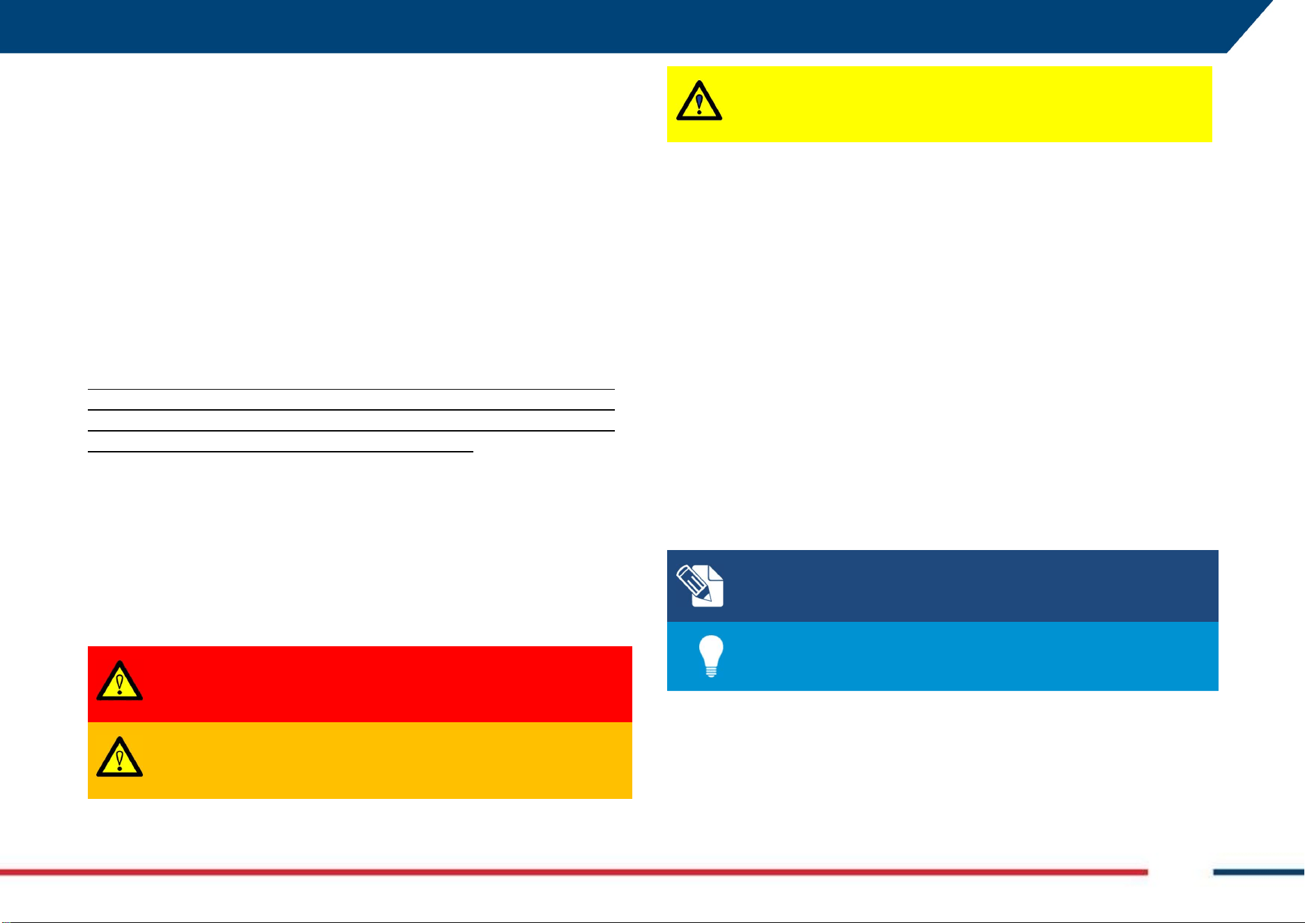
Type Description
DANGER
Indicates an imminently hazardous situation which,
if not avoided, will result in death or serious injury.
WARNING
Indicates a potentially hazardous situation or an
unintended use which, if not avoided, could result
in death or serious injury.
CAUTION
Indicates a potentially hazardous situation or an
unintended use which, if not avoided, may result in
minor or moderate injury.
Warning messages:
• make the user alert about direct and indirect hazards concerning the use
of the product.
• contain general rules of behaviour.
For the user’s safety, all safety instructions and safety messages shall be
strictly observed and followed. Therefore, the manual must always be
available to all persons performing any tasks described herein.
DANGER, WARNING, CAUTION and NOTICE are standardized signal words
for identifying levels of hazards and risks related to personal injury and
property damage.
For your safety it is important to read and fully understand the table below
with the different signal words and their definitions. Supplementary safety
information symbols may be placed within a warning message as well as
supplementary text.
Note text/to keep in mind
Tip information
2 HOW TO READ THE MANUAL Mod: MDM/011/M2 Rev 10
IDS GeoRadar Srl MNG/2025/012 Rev. 1.0 9/ 71
2.3 Glossary & Acronyms
The following acronyms are used in this manual:
Baseline: It is the “virtual” alignment the User should follow to take
pictures of the monitoring scenario at the beginning of any survey
Controller: PC / Tablet used by the user for data acquisition.
GNSS: Global Navigation Satellite System.
GUI: Graphic User Interface
HW: Hardware.
LoS: Line of Sight
MyMo: My Monitoring Station
NMEA format: National Marine Electronics Association format.
OTA updates: Over-the-Air updates
RTK: Real Time Kinematic.
SNR: Signal to Noise Ratio.
SW: Software.
SAP (follow by 6-digit): ID code to identify the part number
SHM: Structural Health Monitoring
3 SAFETY DIRECTIONS Mod: MDM/011/M2 Rev 10
IDS GeoRadar Srl MNG/2025/012 Rev. 1.0 10/ 71
3. SAFETY DIRECTIONS
The following directions enable the person responsible for the product, and
the person who uses the equipment, to anticipate and avoid operational
hazards.
The person responsible for the product must ensure that all users understand
these directions and adhere to them.
3.1 Intended Use
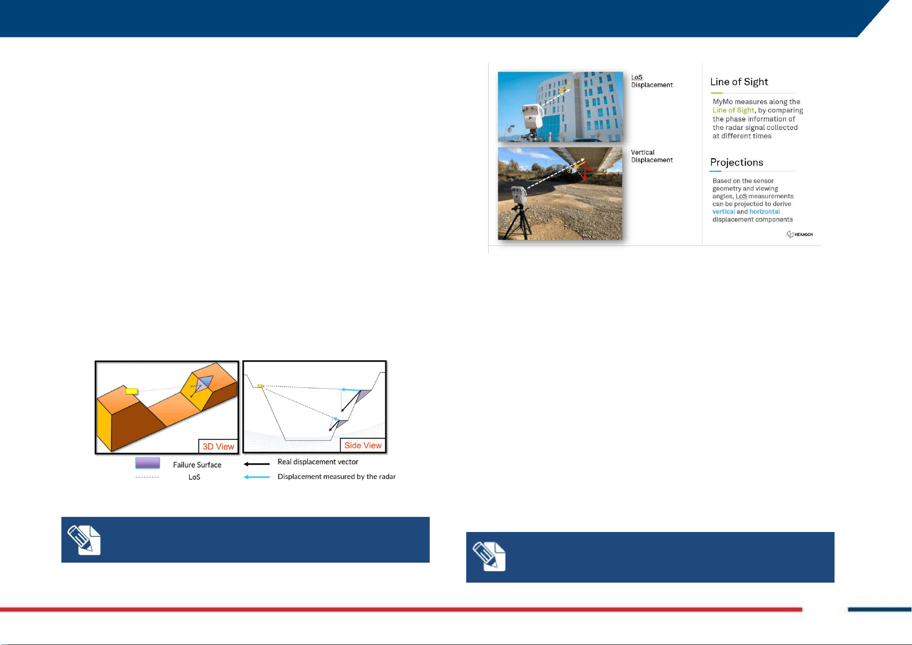
The intended use of MyMo is the remote measurement of surface slow
displacement measured along the Line of Sight (LoS) direction (Fig. 1) or
Projections (Fig. 2) in the following environments:
open pits, mines and quarries
natural landslides
tailing dams
structures (building, dams, bridges, towers, etc…)
Fig. 1 Line of Sight displacement
In case the movement direction is orthogonal to the LoS, the
system will measure ZERO displacement
Fig. 2 LoS and Projections
3.2 Reasonably Foreseeable Misuse
Below are listed a list of possible misuse of the system to be avoided:
Use of the product without instruction
Use outside of the intended use and limits
Disabling safety systems
Removal of hazard notices
Opening the product using tools, for example screwdriver, unless
this is permitted for certain functions
Modification or conversion of the product
Use after misappropriation
Use of products with obvious damage or defects
Use with accessories from other manufacturers without the prior
explicit approval of IDS GeoRadar S.r.l.
Inadequate safeguards at the working site.
NOTE: The product is intended for professional use only; not
for consumers use.

3 SAFETY DIRECTIONS Mod: MDM/011/M2 Rev 10
IDS GeoRadar Srl MNG/2025/012 Rev. 1.0 11/ 71
3.3 Limits of Use
MyMo operating temperature ranges from -20°C to +55°C. The upper
temperature limit is reduced to +40°C with direct sunlight radiation. Lower
operating temperature can be achieved by installing the system inside a
shelter with a proper opening to allow the transmission of the signal emitted
by MyMo (container or similar housing).
Environment: Suitable for use in an atmosphere appropriate for permanent
human habitation. Not suitable for use in explosive environments.
WARNING
:
POTENTIALLY HAZARDOUS AREAS
working in hazardous areas, such as potentially explosive areas, or
close to electrical installations, or similar situations, could result
in death or serious injury.
PRECAUTION: Local safety authorities and safety experts must be
contacted, by the person in charge of the product, prior
commencing any survey in potentially hazardous areas for the due
risk assessment.
3.4 Responsibilities
Manufacturer of the product: IDS GeoRadar S.r.l is responsible for supplying
the product, including the user manual and original accessories, in a safe
condition.
Person responsible for the product: the person responsible for the product
has the following duties:
to understand the safety instructions on the product and the
instructions in the user manual
to ensure that it is used in accordance with the instructions
to be familiar with local regulations relating to safety and accident
prevention
to inform IDS GeoRadar S.r.l. immediately if the product and the
application become unsafe
to ensure that the national laws, regulations and conditions for the
operation of electromagnetics transmitters are respected.
NOTICE
:
Watch out for erroneous measurement results if the
product has been dropped, misused, modified, or stored for
long periods.
Precautions:
Periodically carry out test measurements.
3 SAFETY DIRECTIONS Mod: MDM/011/M2 Rev 10
IDS GeoRadar Srl MNG/2025/012 Rev. 1.0 12/ 71
3.5 Hazard of Use
WARNING
:
CRUSHING HANDS, FINGERS AND TOES
While installing and using the system, the risk of fingers
pinching out may occur.
PRECAUTION: To mount and use the system, the user must
always wear protective gloves and safety boots.
WARNING
:
RISK OF ACCIDENTS
During surveys there is a danger of accidents occurring if the
user does not pay attention to the surrounding site
conditions, such as obstacles, excavations, or traffic.
PRECAUTIONS: During operations, the user of the product
must be fully aware of the existing site conditions, and
potential dangers.
WARNING: ELECTROCUTION
Because of the risk of electrocution, it is dangerous to use
poles and extensions near electrical installations such as
power cables or electrical railways.
PRECAUTIONS: Keep at a safe distance from electrical
installations. If it is essential to work in this environment,
first contact the safety authorities responsible for the
electrical installations and follow their safety instructions.
NOTICE
: If the accessories used with the product are not
properly secured and the product is subjected to mechanical
shock, for example blows or falling, the product may be
damaged.
Precautions:
When setting up the product, make sure that the accessories
are correctly adapted, fitted, secured, and locked in position.
Avoid subjecting the product to mechanical stress.
WARNING: SECURING OF THE WORKING SITE
Inadequate securing of the working site can lead to
dangerous situations, for example in traffic, on building
sites, and at industrial installations.
PRECAUTIONS: Always ensure that the working site is
adequately secured. Adhere to the regulations governing
safety, accident prevention, and road traffic.
3 SAFETY DIRECTIONS Mod: MDM/011/M2 Rev 10
IDS GeoRadar Srl MNG/2025/012 Rev. 1.0 13/ 71
WARNING: LIGHTING STRICKING
If the product is used with accessories (for example GNSS
pole support), the user may increase the risk of being
struck by lightning.
PRECAUTIONS: Do not use the product during
thunderstorm.
WARNING: EXPOSURE OF BATTERIES TO HIGH
MECHANICAL STRESS, HIGH AMBIENT TEMPERATURE
OR IMMERSION INTO FLUIDS
High mechanical stress, high ambient temperatures or
immersion into fluids can cause leakage, fire, or
explosions of the batteries.
PRECAUTIONS: Protect the batteries from mechanical
influences and high ambient temperatures. Do not drop
or immerse batteries into fluids.
WARNING
:
MECHANICAL INFLUENCES ON BATTERIES
During the transport, shipping, or disposal of batteries it
is possible, for inappropriate mechanical influences, to
constitute a fire hazard.
PRECAUTIONS: Before shipping the product or disposing
of it, discharge the batteries by running the product until
they are flat. When transporting or shipping batteries,
the person in charge of the product must ensure that the
applicable national and international rules and
regulations are observed. Before transportation or
shipping, please contact your local passenger or freight
transport company.
3 SAFETY DIRECTIONS Mod: MDM/011/M2 Rev 10
IDS GeoRadar Srl MNG/2025/012 Rev. 1.0 14/ 71
NOTICE: Only IDS GeoRadar authorized technical service are
entitled to repair this product.
WARNING
:
Short circuit of battery terminals
Risk of fire, electric shock, and damage.
PRECAUTIONS: Keep away any metallic or wet objects from
the battery terminals inside battery housing.
WARNING
:
Short circuit of battery terminals
If battery terminals are short-circuited e.g., by coming in
contact with jewellery, keys, metallised paper or other metals,
the battery can overheat and cause injury or fire, for example
by storing or transporting in pockets.
PRECAUTIONS: Make sure that the battery terminals do not
come into contact with metallic objects.
WARNING
:
Battery may get hot after prolonged use.
Risk of burning injuries.
PRECAUTIONS: Avoid touching the hot battery. Allow the
battery to cool down before removing it.
NOTICE: If the product is improperly disposed, the following can
happen:
• If polymer parts are burnt, poisonous gases are produced
which may impair health.
• If batteries are damaged or are heated strongly, they can
explode and cause poisoning, burning, corrosion or
environmental contamination.
• By disposing of the product irresponsibly you may enable
unauthorized persons to use it in contravention of the
regulations, exposing themselves and third parties to the risk of
severe injury and rendering the environment liable to
contamination.
RECYCLING
The crossed out wheeled bin symbol shown on the equipment
indicates that the product must be recycled separately from
other waste at the end of its useful life.
Separate waste disposal of this product at the end of its useful
life will be organised and managed by IDS GeoRadar. When you
decide to dispose of the equipment, contact IDS GeoRadar and
follow the system that IDS GeoRadar has set up to permit the
separate collection of the apparatus at its life end.
Adequate separate collection for its subsequent recycling,
treatment and environmentally friendly disposal contributes
towards avoiding any unnecessary effects on the environment
and to health and favour the reuse or recycling of the materials
that make up the equipment. Unauthorised disposal of this
product as unsorted waste by its possessor will lead to an
administrative penalty foreseen by national regulations.
4 CYBERSECURITY Mod: MDM/011/M2 Rev 10
IDS GeoRadar Srl MNG/2025/012 Rev. 1.0 15/ 71
4. CYBERSECURITY
This section includes cybersecurity characteristics of MyMo, its interfaces
exposed to risk of cyberattacks, and the actions needed to grant the safe use
of this device.
NOTICE: Users must read carefully this section before
installation and use of the device.
4.1 MyMo Interfaces
4.1.1 Physical interfaces
MyMo, includes the following interfaces:
Ethernet Port (RJ45) – For cabled network connection; it supports
protocol FTPS, HTTPS, DHCP (client), DNS (client), SNTP (client).
Ethernet Port (RJ45) – For cabled connection with a PC controller; it
supports protocols HTTPS, DHCP (server), DNS (server).
HotSpot WiFi – for wireless connection with a PC Controller; it
supports protocols HTTPS, DHCP (server), DNS (server).
WiFi – for network wireless connection; it supports protocols FTPS,
HTTPS, DHCP (client), DNS (client), SNTP (client).
LTE module – for internet access; it supports protocols FTPS, HTTPS,
DHCP (client), DNS (client), SNTP (client).
NOTICE: Do not connect any accessory or third party’s device
to these ports unless trusted.
4.1.2 Network interfaces and supported protocols
MyMo can transfer data and/or receive Over-The-Air (OTA) updates via Wi-
Fi, 4G and Ethernet.
Network active services are:
SSH (port 61531): Access to the system, for authorized technical
personnel ONLY.
HTTPs (port 443): access to Users application
SNTP client (port 123): Tyme synchronization with remote server
DHCP server (port 67): to assign IP address to the Controller PC
DHCP client (port 68): to obtain IP address for cabled and non-
cabled interfaces towards the network
DNS client/server (port 68): to resolve local or remote domain
name
Protected protocols:
TLS version 1.3 encryption RSA-4096/AES-256/WPA2 AES-CCMP
4.2 Software updates and cybersecurity
To grant protection to vulnerability, the device supports software updates:
Updates modes: automatic and/or manual.
Channel of updating: OTA encrypted or through dedicated App
Update Server: authenticated and with digital signature
It is strongly suggested to keep the device always updated.
4.3 Duration of Safety support
IDS GeoRadar grants the availability of cybersecurity periodic updates.
4 CYBERSECURITY Mod: MDM/011/M2 Rev 10
IDS GeoRadar Srl MNG/2025/012 Rev. 1.0 16/ 71
4.4 Data Protection and Safe Communications
All data transmitted between MyMo and remote services are protected by
end-to-end encryption. This device does not handle personal data.
4.5 Suggested settings for safe use
To minimize risk connected to cybersecurity, it is recommended to:
Peridically change WiFi password
Disable interfaces when not in use
connect the device only to trusted network
place the device in a safe site from the accessibility point of view
always install the latest software updates available
4.6 Handling vulnerability and incidents
IDS GeoRadar maintains an internal process to handle cybersecurity
vulnerability.
In case of any suspect or actual cybersecurity issues unplug the system and
report it immediately using the technical support e-mail address:
o support.mining@idsgeoradar.com , or
o sup[email protected]m
4.7 Limitations and safety warnings
Do not alter or modify either the firmware or the interfaces of the
device, unless specifically guided and/or requested by IDS GeoRadar
srl.
Using the device in open areas with no protection whatsoever may
increase the risk of cyberattack.
It is strongly recommended not to connect the device to open, public
networks.
5 GENERAL DESCRIPTION Mod: MDM/011/M2 Rev 10
IDS GeoRadar Srl MNG/2025/012 Rev. 1.0 17/ 71
5. GENERAL DESCRIPTION
MyMo system by IDS GeoRadar srl, is designed to detect displacements,
along the Line of Sight (LoS), of vertical buildings (e.g.: towers or dams),
horizontal buildings (e.g.: bridges or overpasses), natural or manmade slopes
(e.g.: landslides and open pits).
For the above-mentioned field of applications static, dynamic, contact-less,
and up to 400 meters distance (from radar head sensor) monitoring
campaigns, can be carried out.
NOTICE: The maximum monitoring distance reached by the
system may also depend on both the acquisition geometry and
the “Radar signal reflectivity” of the monitored scenario.
MyMo hardware and software are customized in specific packages and
accessories, to optimize the final use and specific application.
In this respect, MyMo system by IDS GeoRadar can include a Base package
but also accessories and different field SW packages.
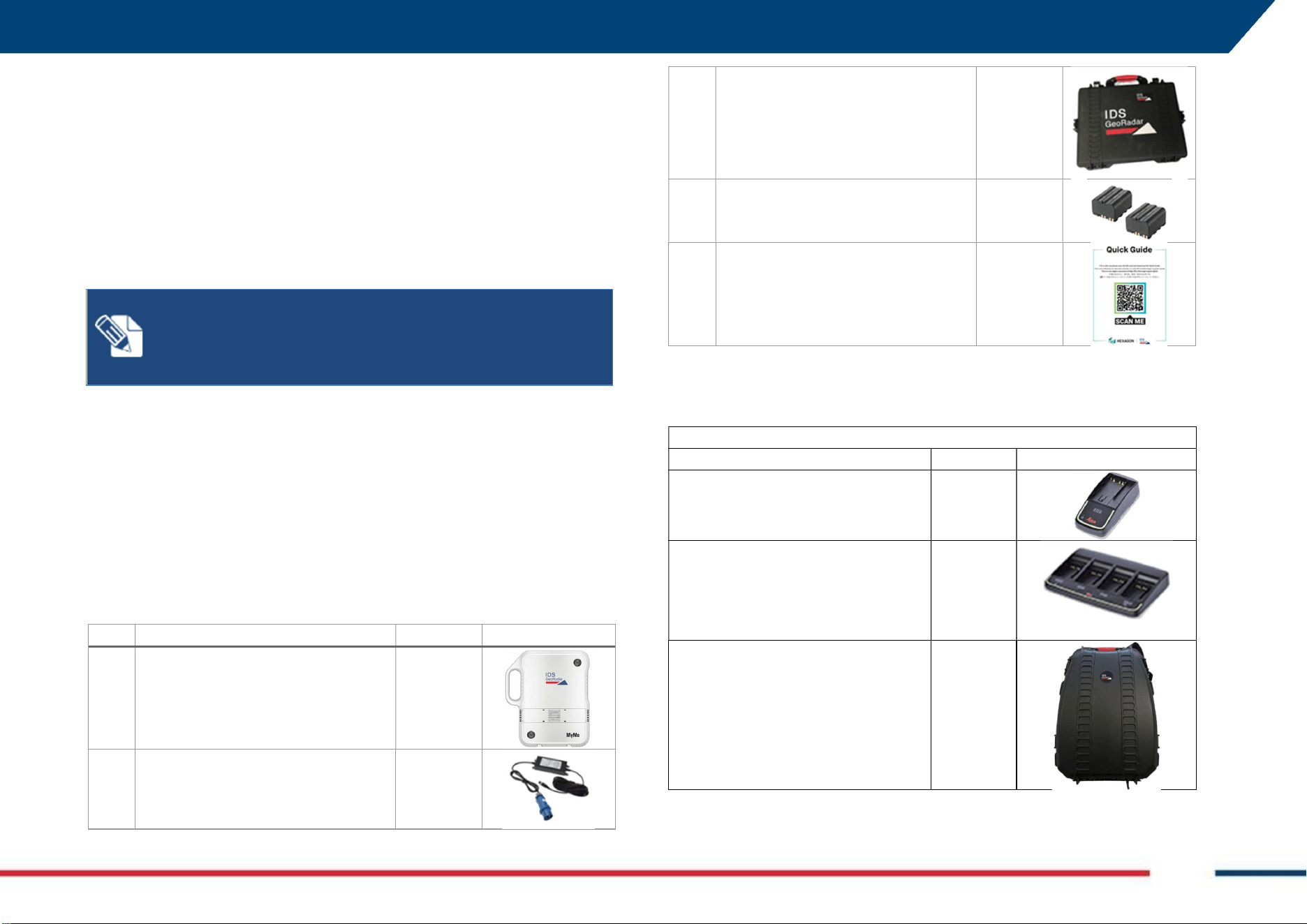
5.1 MyMo System Base
The following items are included in the Base package:
Q
.
ty
Description
SAP Code
Image
1
MyMo Sensor
995941
1
110V
-
220V AC
-
DC to 24V 185W
Power Supply
1015496
1
MyMo transport case
1038057
2
GEB461 Battery
973449
1
Quick guide access flyer
994784
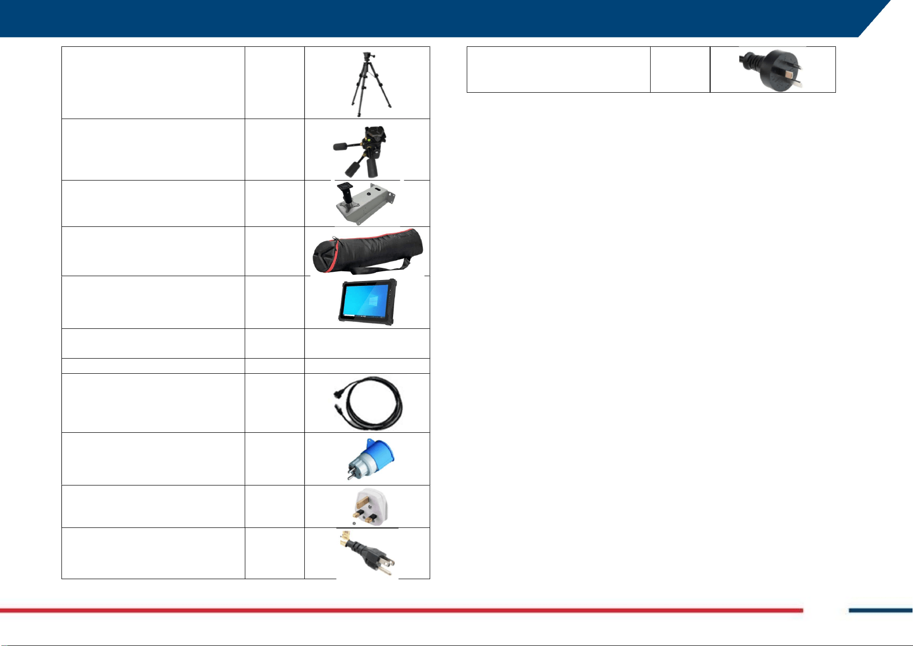
5.2 MyMo Base Accessories
The following accessories for the Base package are available:
ACCESSORIES
Description
SAP Code
Image
GKL311, Charger Pro 3000
799185
GKL341, Charger Pro 5000
799187
MyMo Backpack
1045845
5 GENERAL DESCRIPTION Mod: MDM/011/M2 Rev 10
IDS GeoRadar Srl MNG/2025/012 Rev. 1.0 18/ 71
Tripod
860954
Tilting head for tripod
860953
MyMo Fixed Mount Kit
1047900
Tripod transportation bag
1031137
Tablet Panasonic FZ
-
G2
968919
US Keyboard for Panasonic FZ
-
G2
968921
Battery for FZ
-
G2
968922
Chaser LAN cable 2.5m 987232
Main power cable adapter Schuko 858998
Main power cable adapter BS1363 858999
Main power cable adapter NEMA
5-15
859000
Main power cable adapter AS/NZS
3112
859001
5 GENERAL DESCRIPTION Mod: MDM/011/M2 Rev 10
IDS GeoRadar Srl MNG/2025/012 Rev. 1.0 19/ 71
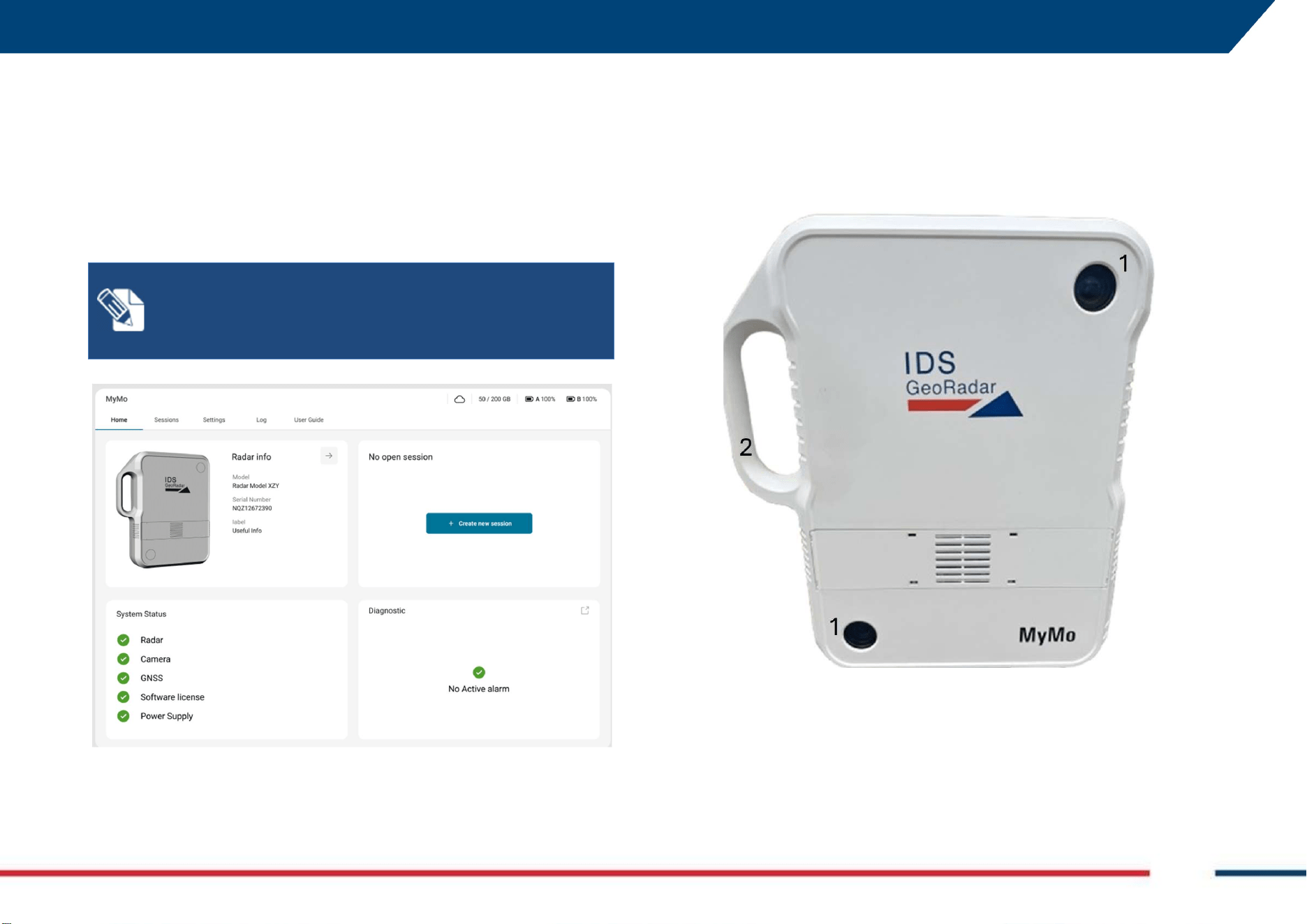
5.3 MyMo Field App
To run MyMo on field it is necessary to use a web app running on web
browser named MyMo Field App (Fig. 3Fig. 1). It can be installed and used as
perpetual license or time limited.
Moreover, MyMo Field App license can be activated to allow for variable
distance-to-target survey.
For more details on licensing, refer to the local IDS GeoRadar Representative.
Fig. 3 MyMo Field App Home Page
5.4 MyMo Sensor Description
MyMo front view includes the following:
1. 2 cameras for stereoscopic imagery of the monitoring scenario,
2. Handle (front view).
NOTICE:
An active internet connection is needed during the
license activation of MyMo Web App and the get started
procedure (“unboxing”). During monitoring instead, it is NOT
mandatory to have an active internet connection.
5 GENERAL DESCRIPTION Mod: MDM/011/M2 Rev 10
IDS GeoRadar Srl MNG/2025/012 Rev. 1.0 20/ 71
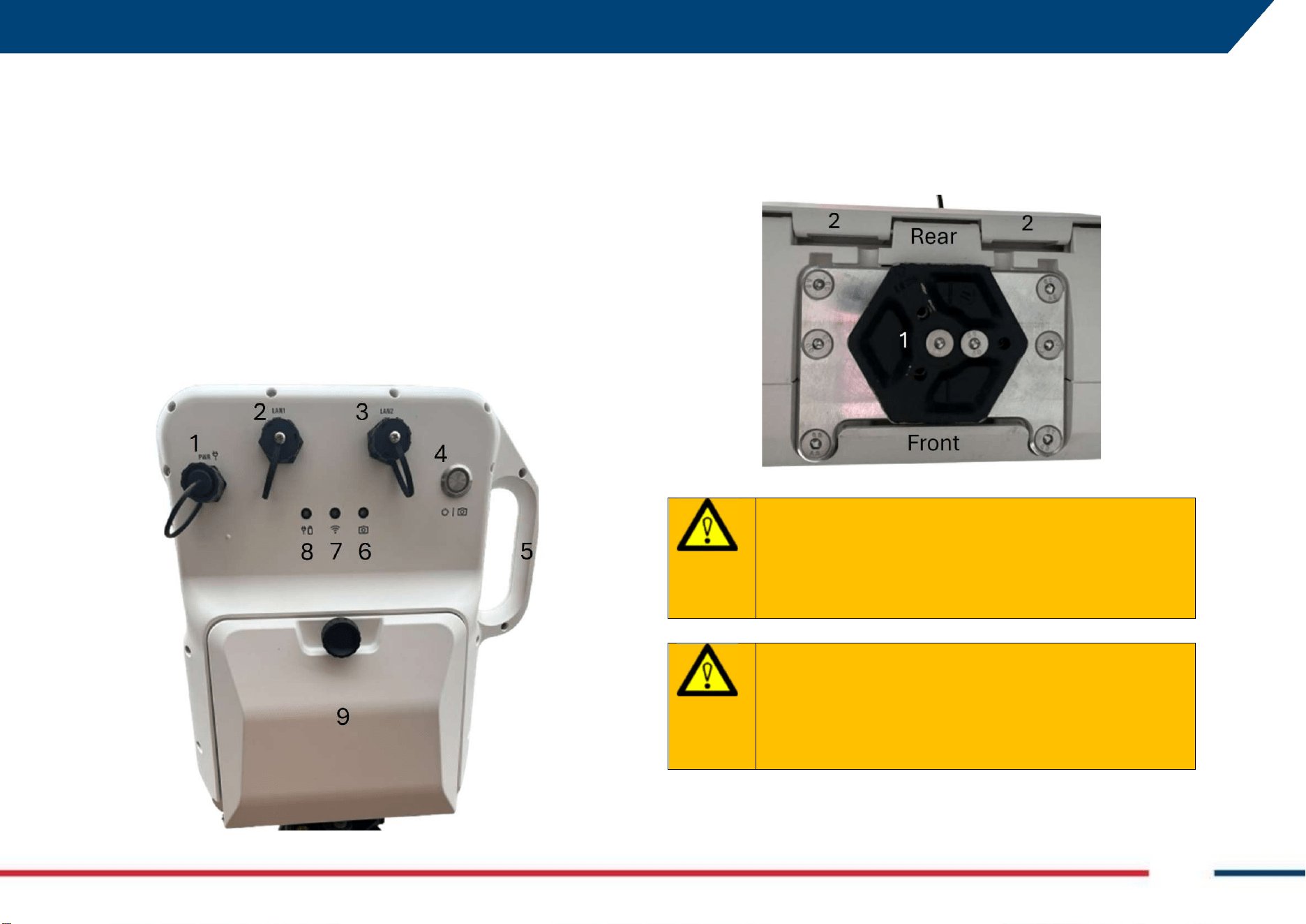
MyMo rear view includes the following:
1. Power Connector (to connect the power supply)
2. LAN 1 port (for internet)
3. LAN 2 port (connection to PC)
4. 0/I Button (ON/OFF). Also used for shooting photos of the
monitoring scenario,
5. Handle (rear view),
6. Camera LED,
7. WiFi LED
8. Power supply/Battery Status LED
9. Battery compartment.
MyMo bottom view includes the following:
1. Hexagonal metal plate to pair MyMo head sensor with tripod’s tilting
head,
2. Hookups of the battery compartment.
WARNING
:
System Malfunctioning due to batteries
Using non-specific batteries may cause malfunction, damage
to the device, or safety hazards
PRECAUTION: Use only the specified battery type (Leica
GEB461
WARNING
:
System Malfunctioning due to battery charger
Using non-specific battery charger may cause malfunction,
damage to the device, or safety hazards
PRECAUTION: Use only the specified power supply type (MW
HLG-185H-24)
6 HOW TO SET UP MYMO AND ACCESSORIES Mod: MDM/011/M2 Rev 10
IDS GeoRadar Srl MNG/2025/012 Rev. 1.0 21/ 71
6. HOW TO SET UP MYMO AND ACCESSORIES
Installing MyMo on site is the first operation to be carried out prior to any
monitoring activity.
Like any other interferometric survey, monitoring with MyMo relies on signal
phase difference measurements gathered along the LoS between MyMo and
the target to be monitored. Hence, installation is a critical operation to
optimize the result of the survey.
In general, the installation of MyMo with respect to target, depends on
factors, including but not limited to:
MyMo distance-to-target (tower, slope, open pit wall, bridge,
building…),
Shape of the target,
Radar signal reflectivity of the target,
Width of the area to be monitored,
Site accessibility,
Interference with external noise (road traffic, working machines,
any nearby source of vibration…)
Depending on accessories purchased, MyMo can be installed:
On Tripod, or
On Fixed Mount Kit
In the following pages, general installation instructions are illustrated.
WARNING
:
CRUSHING HANDS, FINGERS AND TOES
While installing and using the system, the risk of fingers
pinching out may occur.
PRECAUTION: To mount and use the system, the user must
always wear protective gloves and safety boots.
6.1 How to set up MyMo on Tripod
To set up MyMo on tripod, follow the steps below:
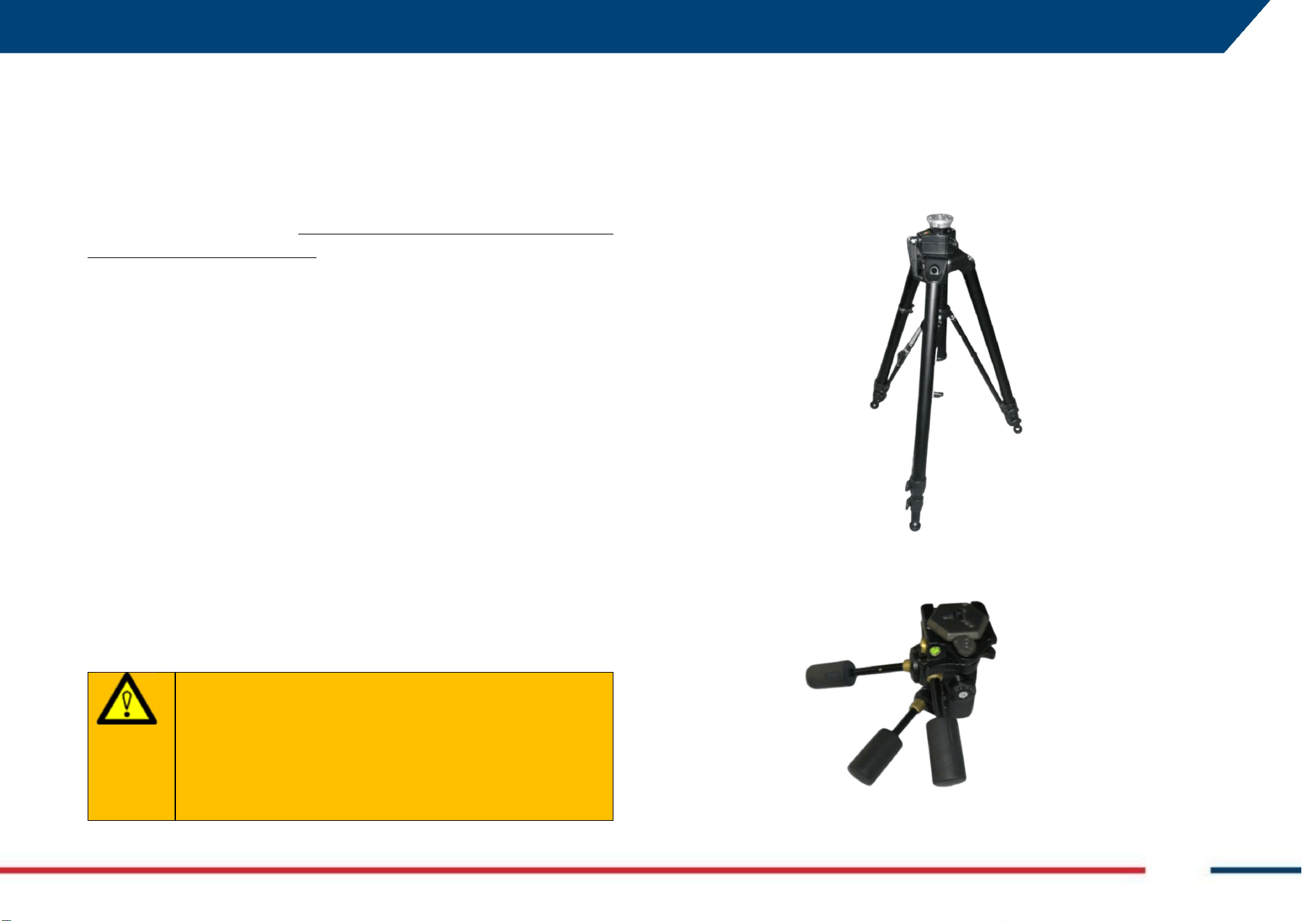
1. Take off the tripod from its bag and place it vertically, with its “legs”
slightly opened,
2. Take the tilting head off the bag,
6 HOW TO SET UP MYMO AND ACCESSORIES Mod: MDM/011/M2 Rev 10
IDS GeoRadar Srl MNG/2025/012 Rev. 1.0 22/ 71
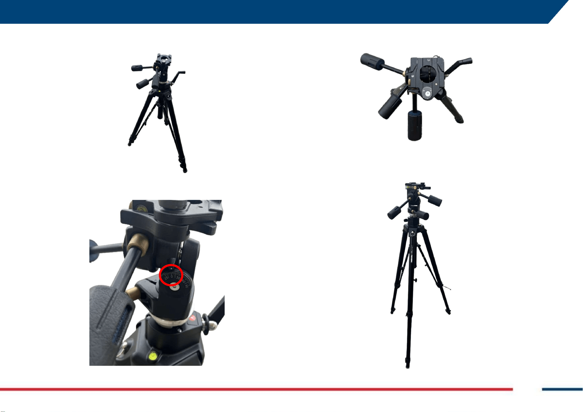
3. Fix the tilting head to the tripod using the screw at the upper end on
top of the tripod,
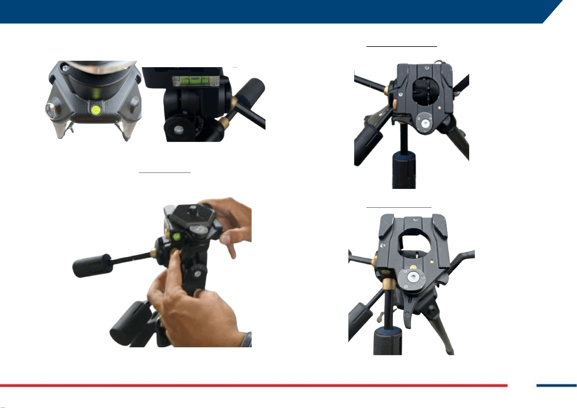
4. Fix and adjust the three knobs (A, B, C in Fig. 4) so that all planes (X-
Z, X-Y, and Y-Z) are set to 0° (red circle below),
5. The tripod, with the tilting head correctly mounted on top, should
now look like the image below (view from top),
6. Adjust the height of the tripod and the opening of its “legs” based on
target to monitor and condition of the surface at the base of the
tripod’s legs,
6 HOW TO SET UP MYMO AND ACCESSORIES Mod: MDM/011/M2 Rev 10
IDS GeoRadar Srl MNG/2025/012 Rev. 1.0 23/ 71
7. Make sure of the correct leveling of the tripod by verifying that tripod
spirit bubbles (left) and tilting head spirit bubbles (right) are correctly
centered,
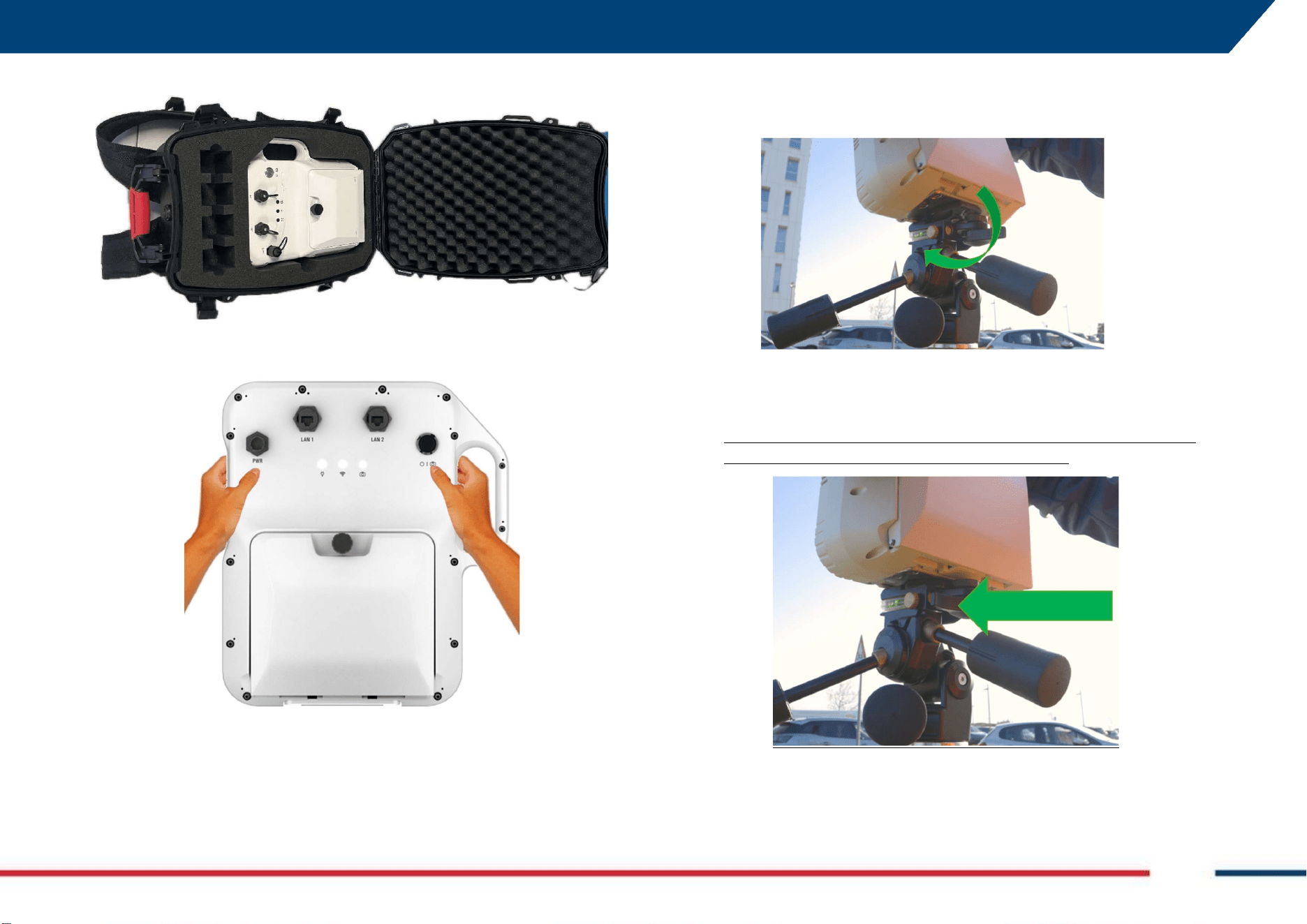
8. By acting anticlockwise, at the same time, on both the two levers at
the left and right side on the top of the tilting head, arm the gear to
host/pair the MyMo sensor with the tripod and tilting head,
9. This (below) is how the tilting head looks when NOT READY to place
MyMo sensor (before arming the gear),
10. This (below) is how it looks the tilting head when READY to place
MyMo sensor (after arming the gear),
6 HOW TO SET UP MYMO AND ACCESSORIES Mod: MDM/011/M2 Rev 10
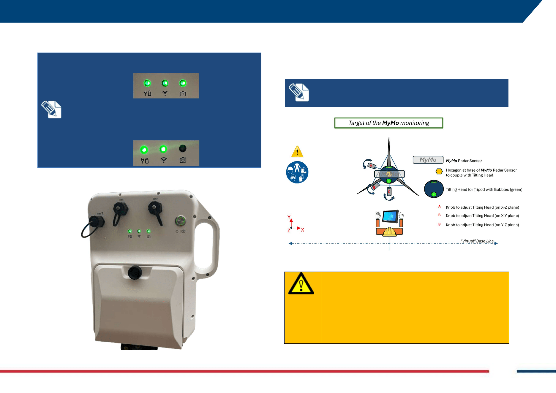
IDS GeoRadar Srl MNG/2025/012 Rev. 1.0 24/ 71
11. Take off MyMo from its container,
12. Hold the sensor with both hands,
13. slightly fold the top frontwards and place the hexagon part at the
base of the MyMo sensor on top of the mechanism of the tilting head
that has been just “armed”,
14. Still holding MyMo with both hands, slight press backwards, until
hear a “click” indicating that the two levers are back in the initial
position locking the MyMo sensor to the tilting head,
15. Make sure that the left lever is fully at the initial position as this
indicates the correct locking of the MyMo sensor.
16. Open the battery compartment at the back of MyMo, where all plugs
and the O/I button are located,
17. Enter the batteries, and close the battery compartment again,
6 HOW TO SET UP MYMO AND ACCESSORIES Mod: MDM/011/M2 Rev 10
IDS GeoRadar Srl MNG/2025/012 Rev. 1.0 25/ 71
18. Press the O/I button to start the system and MyMo is now ready for
the monitoring session.
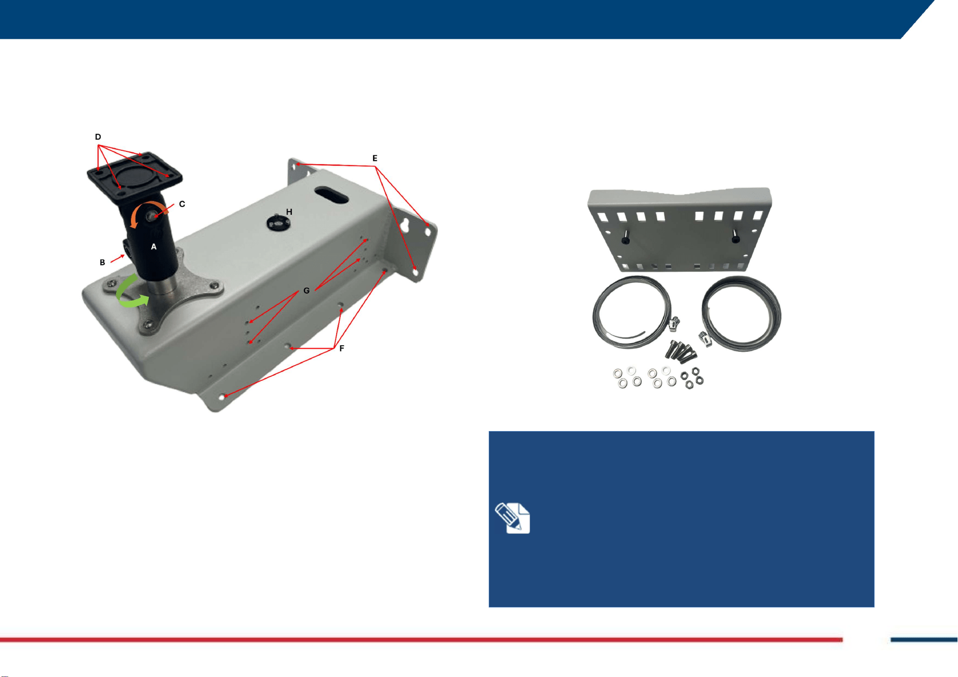
The conceptual sketch of Fig. 4 illustrates, in a schematic way, how MyMo
should be set up before starting a monitoring campaign.
Dashed blue line, behind Operator, is the “so-called” Base Line, that is a
“virtual” line alongside where pictures of the monitoring area should be
taken.
Fig. 4 Sketch of the MyMo installation (View from top)
WARNING
:
CRUSHING HANDS, FINGERS AND TOES
While installing and using the system, the risk of fingers
pinching out or other accidents may occur.
PRECAUTION: During installation and use, ensure that the
tripod is positioned securely and stably, and that the sensor
is properly mounted and firmly attached to its dedicated
support
NOTICE:
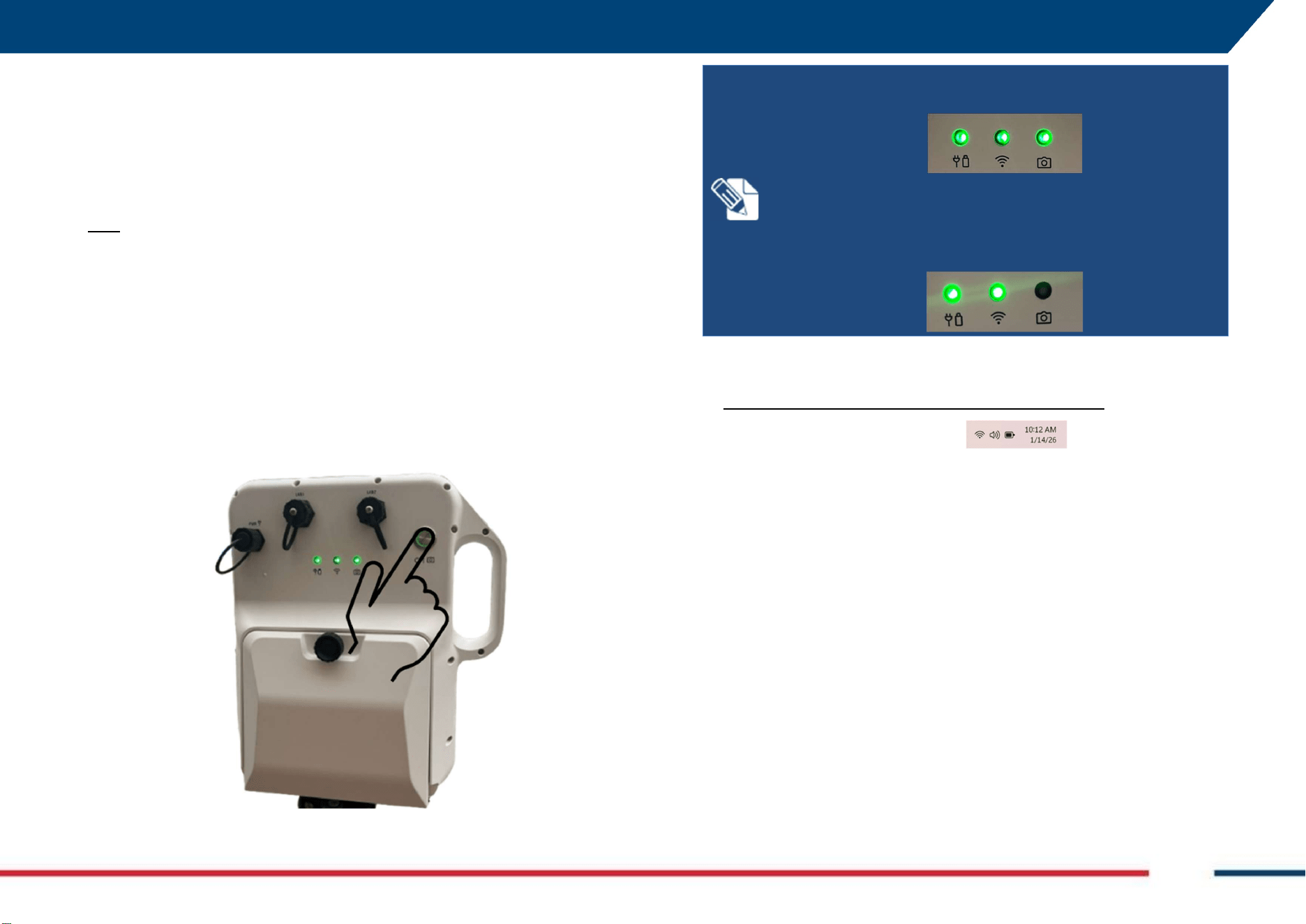
For MyMo to power on, hold the O/I button for about
6 seconds until the LEDs turns from white to green.
After each start, MyMo perform a Buil-in-Test of the internal
electronic. This operation takes about 3 minutes and after that
the system is ready. Now, only battery and WiFi LEDs shall be
on solid green.
NOTICE: The higher the distance between MyMo and the
target, the longer the Base Line.
6 HOW TO SET UP MYMO AND ACCESSORIES Mod: MDM/011/M2 Rev 10
IDS GeoRadar Srl MNG/2025/012 Rev. 1.0 26/ 71
6.2 How to set up MyMo on Fixed Mount Kit
MyMo Fixed Mount Kit (1047900) (Fig. 5) allows MyMo to be installed and
used in those circumstances where the tripod may not be suitable for the
purposes of monitoring.
Fig. 5 Fixed Mount Kit
It includes the following parts:
A. Removable tilting head,
B. Screw to release/fix the tilting head (also allows to orient/move on
the horizontal X-Y plan, the green arrow, after installation and prior
monitoring),
C. Screw to release/fix the tilting head and orient/move along the
vertical Y-Z plan (the orange arrow), after installation and prior
monitoring,
D. Holes to fix the tilting head to the MyMo radar sensor,
E. Holes to fix (using appropriate through bolts) the Fixed Mount kit on
a vertical structure (or to the Pole Mount adapter),
F. Holes to fix (using appropriate through bolts) the Fixed Mount kit on
a horizontal structure,
G. Holes to fix the Power supply,
H. Spirit bubble level.
The Fixed Mount Kit also includes a pole mount adapter (Fig. 6).
Fig. 6 Pole Mount adapter for Fixed Mount Kit
NOTICE:
T
he kit provided by IDS GeoRadar includes
through
bolts with a torque-controlled anchor usually suitable for use in
concrete over C20/25.
Please note that this setup is just a standard configuration and
might not be suitable for all surfaces; to have the Mount Kit
safely fixed, user should perform a preliminary assessment of
the surface.
The choice of the setup to be used for installation of the Mount
Kit, which could include through bolts other than the ones
included in the kit, is under exclusive User’s responsibility.
6 HOW TO SET UP MYMO AND ACCESSORIES Mod: MDM/011/M2 Rev 10
IDS GeoRadar Srl MNG/2025/012 Rev. 1.0 27/ 71
Typical installation conditions for the MyMo Fixed Mount Kit are:
1. A horizontal plan (e.g.: a concrete slab, a floor…),
2. A vertical structure (e.g.: a pillar, a wall…),
3. A vertical pole.
6.2.1 How to prepare the MyMo Fixed Mount Kit
Regardless of where to install MyMo with its Fixed Mount Kit, preliminary
operations to be carried out always include the following steps:
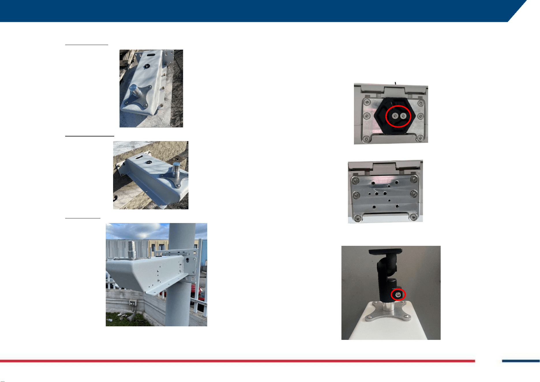
1. Release the (2) screws (inside the red circle, below) fixing the
hexagonal insert at the base of the MyMo radar head sensor,
2. Remove the hexagon insert,
3. Now, release the screw (red circle below) fixing the tilting head (that
is the part in black) on top of the Fixed Mount Kit,
6 HOW TO SET UP MYMO AND ACCESSORIES Mod: MDM/011/M2 Rev 10
IDS GeoRadar Srl MNG/2025/012 Rev. 1.0 28/ 71
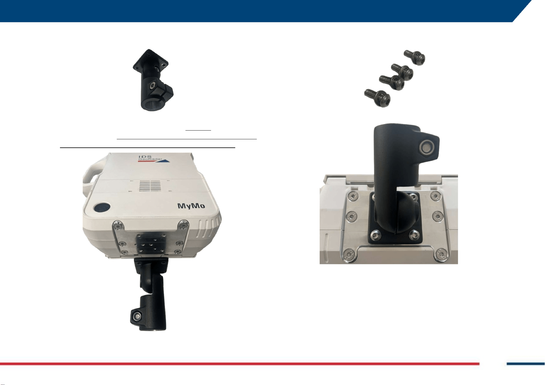
4. Remove now the tilting head from the base of the Fixed Mount Kit,
slightly pulling upward,
5. Place the tilting head at the bottom of the MyMo radar head sensor
where User has just removed the hexagon, EXACTLY as illustrated in
the picture below: this will allow for the correct adjustment along
the YZ and XY plan, before monitoring, and after installation,
6. Using the screws provided, fix the tilting Head to the MyMo radar
head sensor,
7. MyMo is now ready to be installed on Fixed Mount Kit.
6 HOW TO SET UP MYMO AND ACCESSORIES Mod: MDM/011/M2 Rev 10
IDS GeoRadar Srl MNG/2025/012 Rev. 1.0 29/ 71
6.2.2 How to install the Power supply on the Fixed Mount Kit
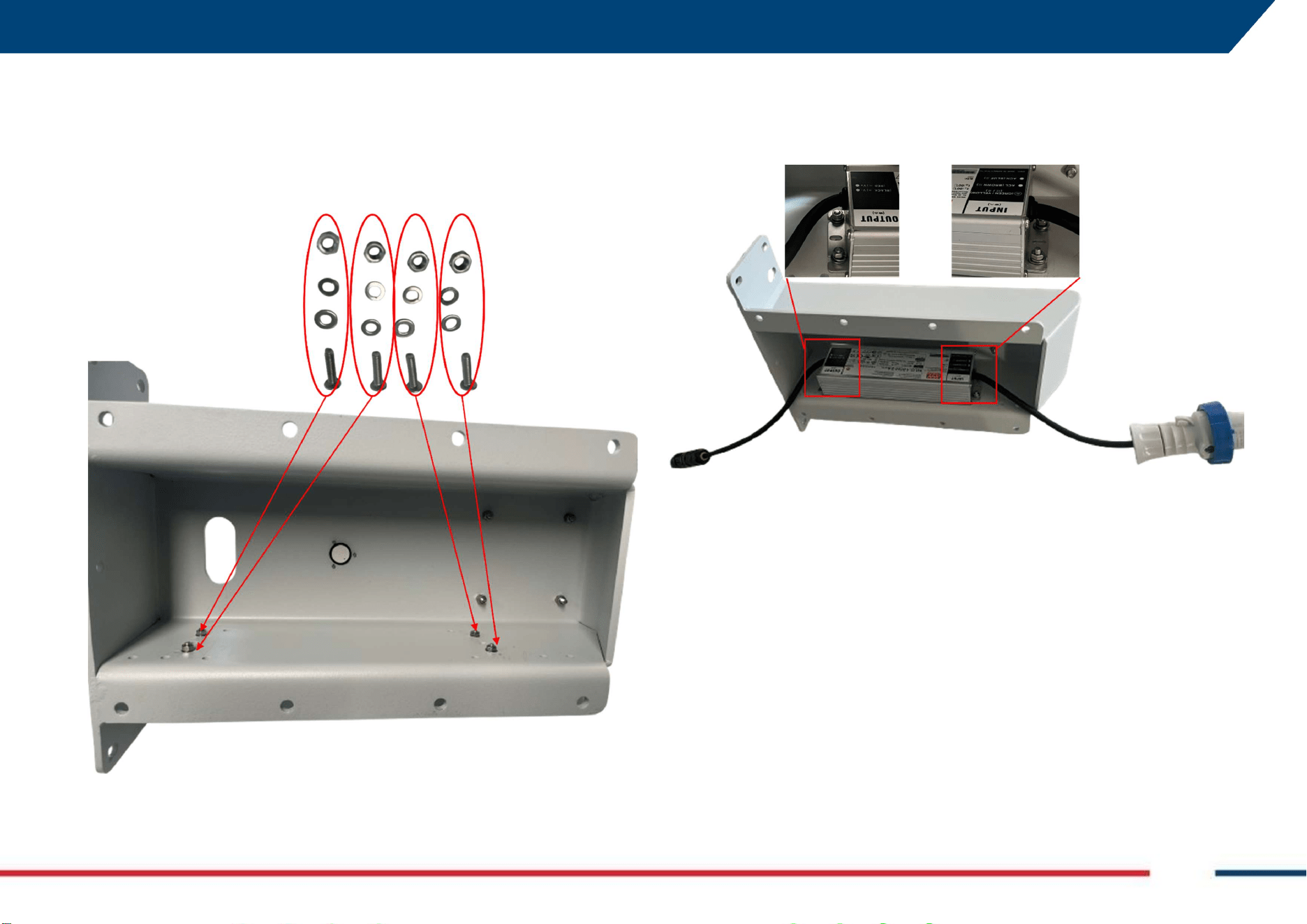
1. With the Fixed Mont Kit upside-down, place the bolts, washers and
nuts provided (using “G” of Fig. 5), and make sure that they are loose,
to allow the correct insert of the power supply,
2. Fit in the Power Supply with the bolts, washers and nuts just placed,
in the same position as in image below and fix the bolts against it,
6 HOW TO SET UP MYMO AND ACCESSORIES Mod: MDM/011/M2 Rev 10
IDS GeoRadar Srl MNG/2025/012 Rev. 1.0 30/ 71
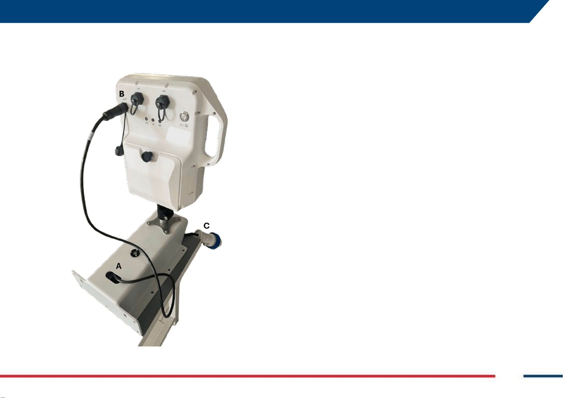
3. Use the cable gland hole (A) to pass the cable and to connect the
output side of the cable to the PWR plug of MyMo (B). Then, connect
“C” to the right adapter, depending on the Region where the system
is used.
6 HOW TO SET UP MYMO AND ACCESSORIES Mod: MDM/011/M2 Rev 10
IDS GeoRadar Srl MNG/2025/012 Rev. 1.0 31/ 71
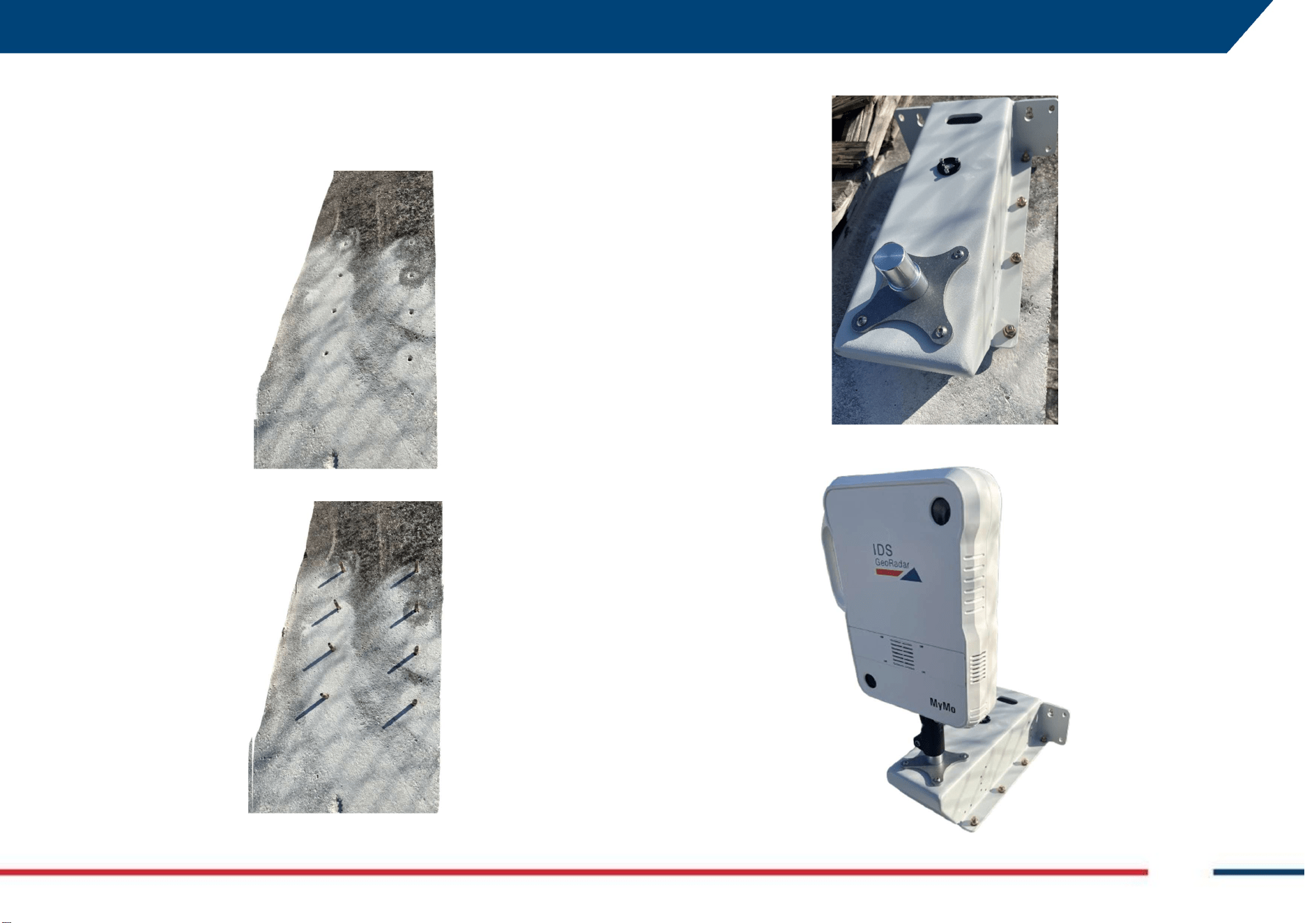
6.2.3 How to install MyMo Fixed Mount Kit on Horizontal Plan
1. Place MyMo Fixed Mount kit on the horizontal plan selected for the
monitoring and sign the points corresponding to the holes (F in Fig.
5). Drill these points with the correct size drilling rig,
2. Now, enter the bolts in the corresponding holes,
3. Fit in the Fixed Mount Kit on the bolts, and fix them,
4. Place MyMo Radar head sensor on top of the Fixed Mount Kit,
6 HOW TO SET UP MYMO AND ACCESSORIES Mod: MDM/011/M2 Rev 10
IDS GeoRadar Srl MNG/2025/012 Rev. 1.0 32/ 71
5. Adjust the heading of MyMo acting on screws B and C of the tilting
head (Fig. 5)
6. Fix the screws B and C before starting the monitoring.
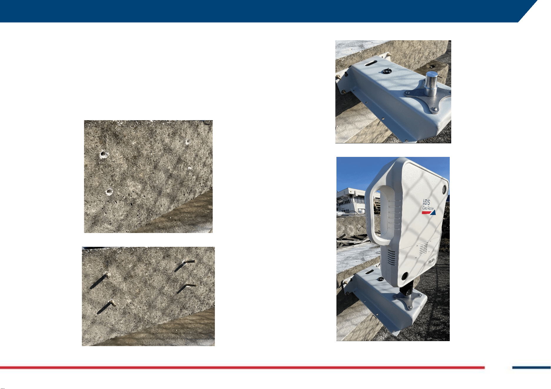
6.2.4 How to install MyMo Fixed Mount Kit on a vertical structure
1. Place MyMo Fixed Mount Kit on the vertical structure selected for
the monitoring and sign the points corresponding to the holes (E in
Fig. 5). Drill these points with the correct size drilling rig,
2. Now, enter the bolts in the corresponding holes,
3. Fit in the Fixed Mount Kit on the bolts and fix them,
4. Place MyMo Radar head sensor on top of the Fixed Mount Kit,
6 HOW TO SET UP MYMO AND ACCESSORIES Mod: MDM/011/M2 Rev 10
IDS GeoRadar Srl MNG/2025/012 Rev. 1.0 33/ 71
5. Adjust the heading of MyMo acting on screws B and C of the tilting
head (Fig. 5)
6. Fix the screws B and C before starting the monitoring.
6.2.5 How to install MyMo Fixed Mount Kit on a vertical Pole
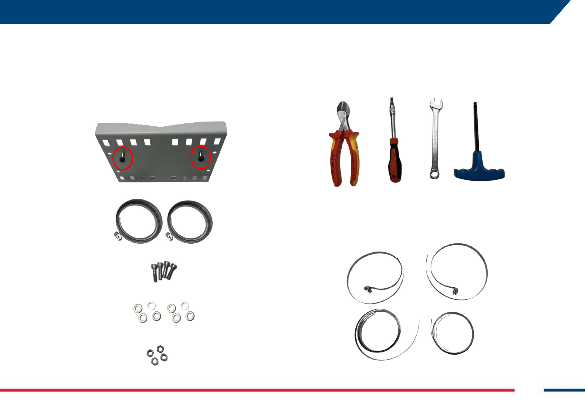
The Pole Adapter for MyMo Fixed Mount Kit (Fig. 6), includes the following
parts:
1. Metal plate with (2) knobs (red circle),
2. (2) Hose clamps,
3. (4) Hexagonal bolts M3x25mm,
4. (8) Washers,
5. (4) locking nuts.
Tools needed to install the pole mount adapter are (from left to right):
Wire cutter
Screwdriver
Wrench (size 13)
Allen Kye (size 6)
To install MyMo using MyMo Fixed Mount Kit on a vertical pole, follow the
steps below:
1. resize of the hose clamps using the wire cutter, if they are too long
for the diameter of the pole to be used for installation,
6 HOW TO SET UP MYMO AND ACCESSORIES Mod: MDM/011/M2 Rev 10
IDS GeoRadar Srl MNG/2025/012 Rev. 1.0 34/ 71
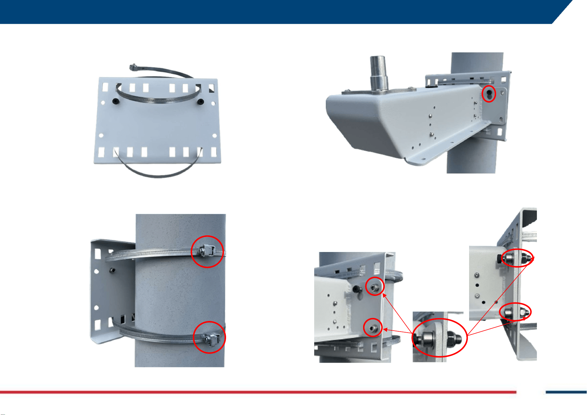
2. Enter the hose clamps in the squared holes in upper and lower part
of the metal plate using the appropriate hole depending on pole
diameter,
3. With knobs upwards, fit the metal plate with hose clamps to the
pole, adjust the heading to the target and fix the hose clamps using
the screwdriver (screws in the red circle),
4. Now place the MyMo Fixed Mount kit on the pole adapter using the
knobs (red circle),
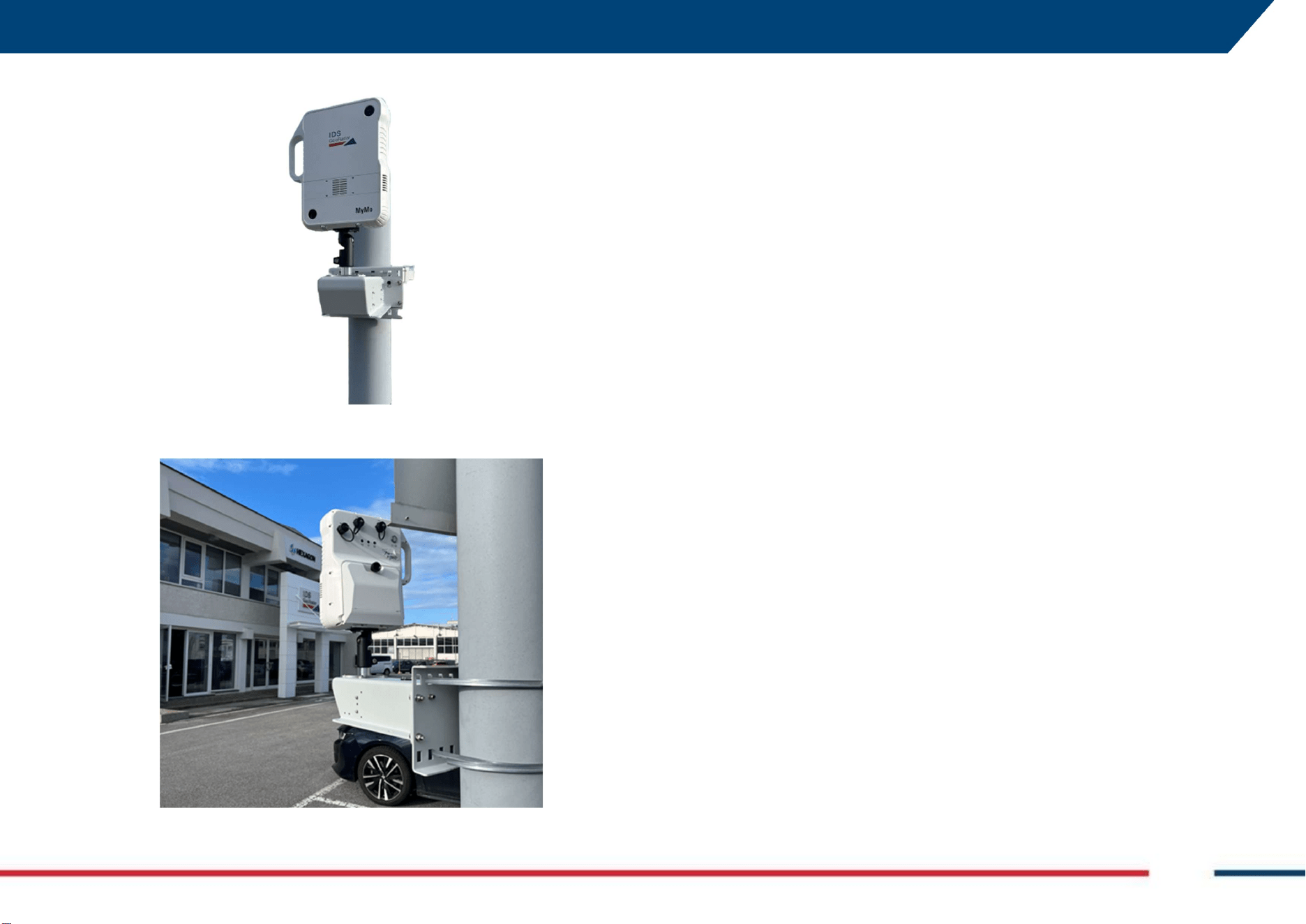
5. Using holes “E” of Fig. 5, fix the Fixed Mount Kit to the Pole Adapter
using the (4) bolts, (8) washers, and (4) locking nuts provided with
the kit.
6 HOW TO SET UP MYMO AND ACCESSORIES Mod: MDM/011/M2 Rev 10
IDS GeoRadar Srl MNG/2025/012 Rev. 1.0 35/ 71
6. Place now MyMo on top on the Fixed Mount Kit just installed,
7. Prior to tightening the tilting head screws, adjust heading towards
the target and the system’s ready to start monitoring.
7 How to get started MyMo Field App Mod: MDM/011/M2 Rev 10
IDS GeoRadar Srl MNG/2025/012 Rev. 1.0 36/ 71
7. How to get started MyMo Field App
Inside MyMo sensor there is an embedded PC where the actual data
acquisition software is installed. Therefore, the PC Controller (i.e.: tablet) is
used to visualize the SW embedded into MyMo and to manage the
monitoring.
Only the first time the User turns on and initialize MyMo the First Access
Configuration Wizard procedure should be performed to get started the
MyMo Field App, that is the web application used to link the PC Controller
and MyMo.
7.1 How to get started MyMo Field App (using WiFi
connection)
To get started MyMo Field App follow the steps below:
1. Turn on MyMo using the O/I button,
2. Turn on the PC Controller,
3. Verify that the internal watch of the PC is synchronized,
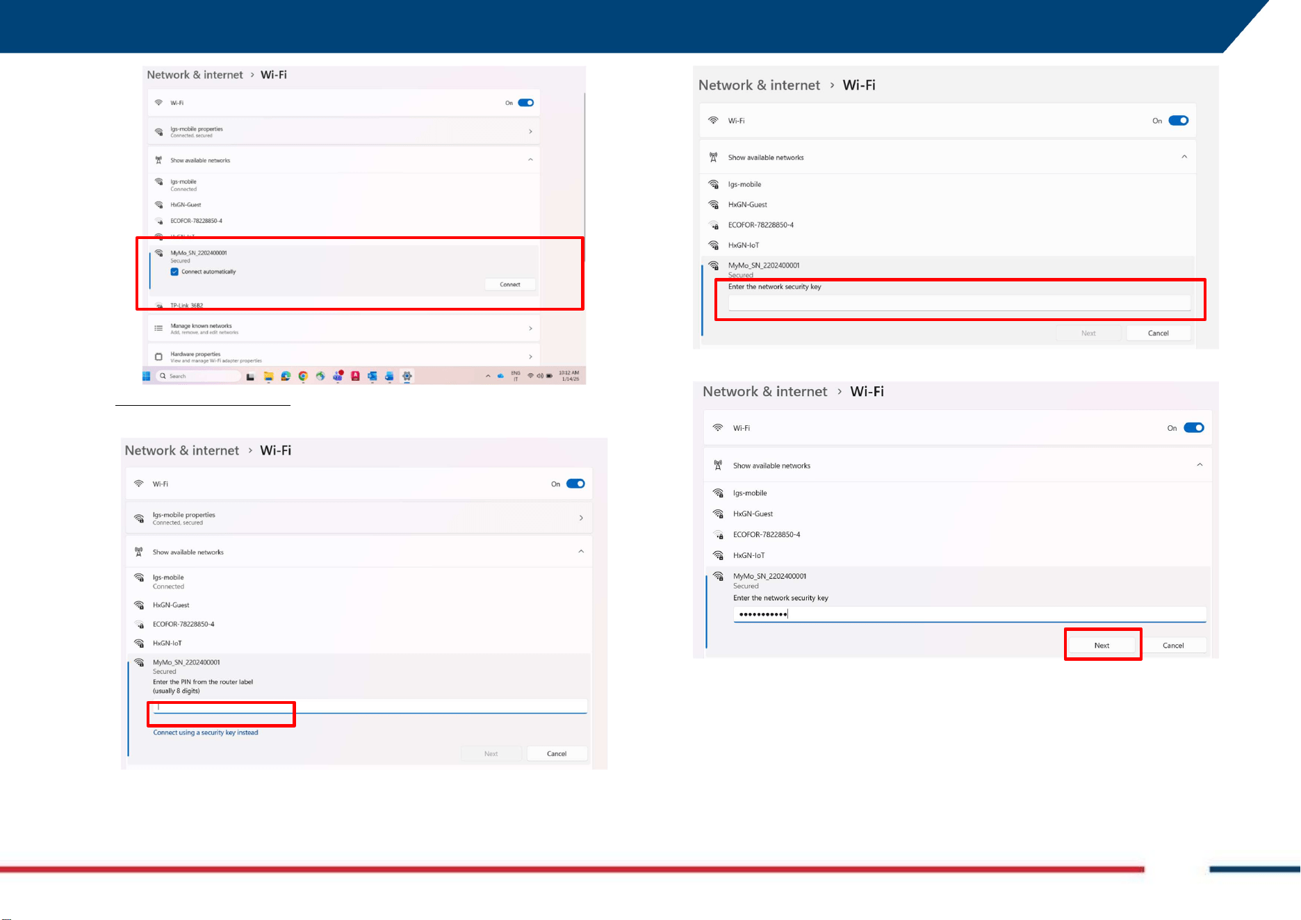
4. Press on the WiFi Network icon on the low right
corner of the Controller desktop and select “MyMo_SN_xxx-xx-
123456” that includes the Serial number of the MyMo in use: press
“Connect”,
NOTICE:
For MyMo to power on, hold the O/I button for about
6 seconds until the LEDs turns from white to green.
After each start, MyMo perform a Buil-in-Test of the internal
electronic. This operation takes about 3 minutes and after that
the system is ready. Now, only battery and WiFi LEDs shall be
on solid green.
7 How to get started MyMo Field App Mod: MDM/011/M2 Rev 10
IDS GeoRadar Srl MNG/2025/012 Rev. 1.0 37/ 71
5. DO NOT ENTER THE PIN, rather press “Connect using a security Key
instead”
6. Enter the security key provided in a flyer inside the delivery package,
7. Press “Next”
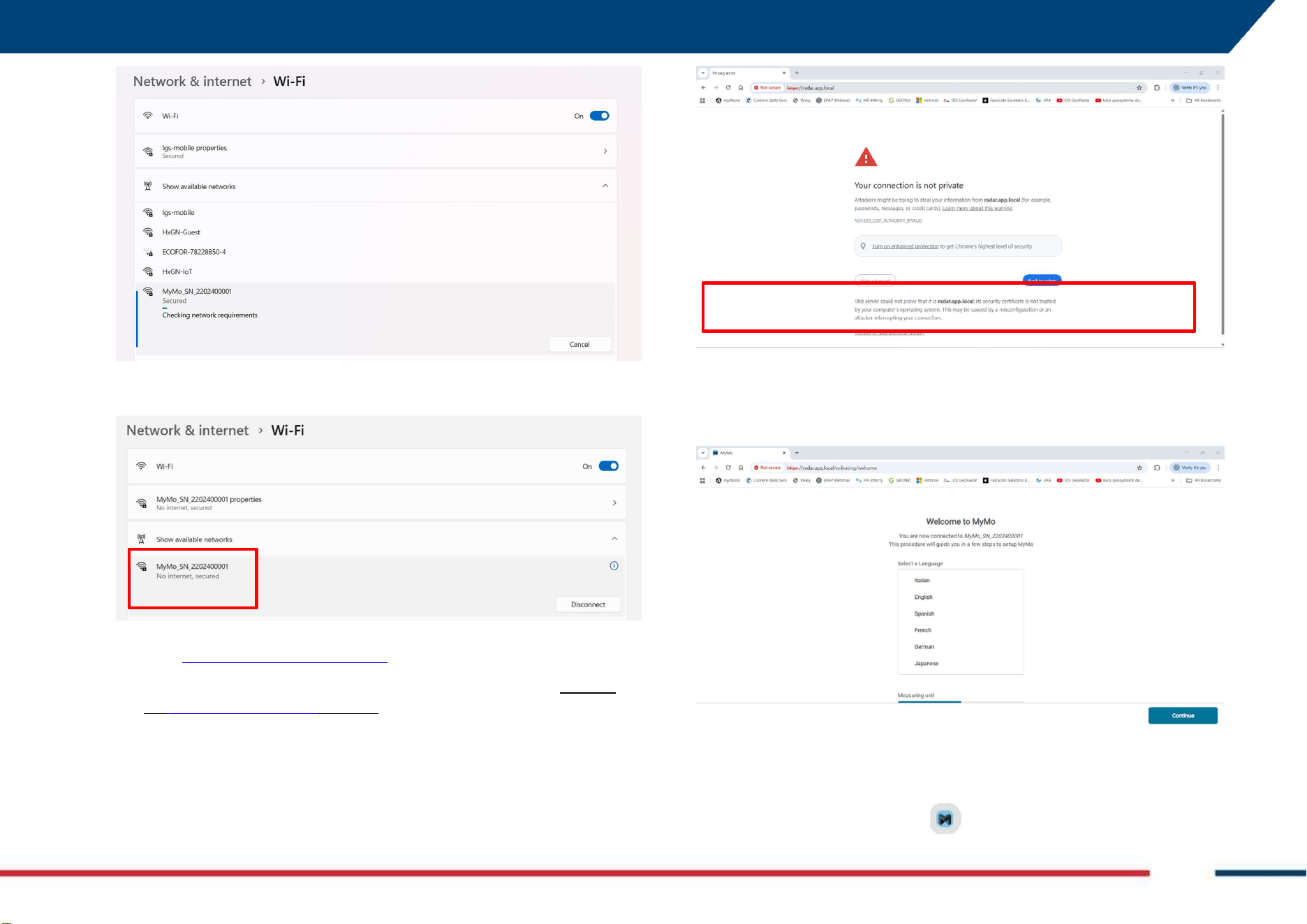
8. Wait for the “Checking network requirements” progress bar to finish,
7 How to get started MyMo Field App Mod: MDM/011/M2 Rev 10
IDS GeoRadar Srl MNG/2025/012 Rev. 1.0 38/ 71
9. And the WiFi connection between the PC Controller and MyMo, is
now established.
10. Launch now the internet browser and
type https://mymo.app.local/login
11. in the URL bar; select “SHOW ADVANCED” and the press “Proceed
to mymo.app.local/login (unsafe)”,
12. This will launch MyMo Web App and prompt the User to the
“Welcome to MyMo” page. Select the preferred language and press
continue,
13. To facilitate future logins, User may save the link to MyMo Field App
to the browser’s bookmark and then copy to the PC desktop,
7 How to get started MyMo Field App Mod: MDM/011/M2 Rev 10
IDS GeoRadar Srl MNG/2025/012 Rev. 1.0 39/ 71
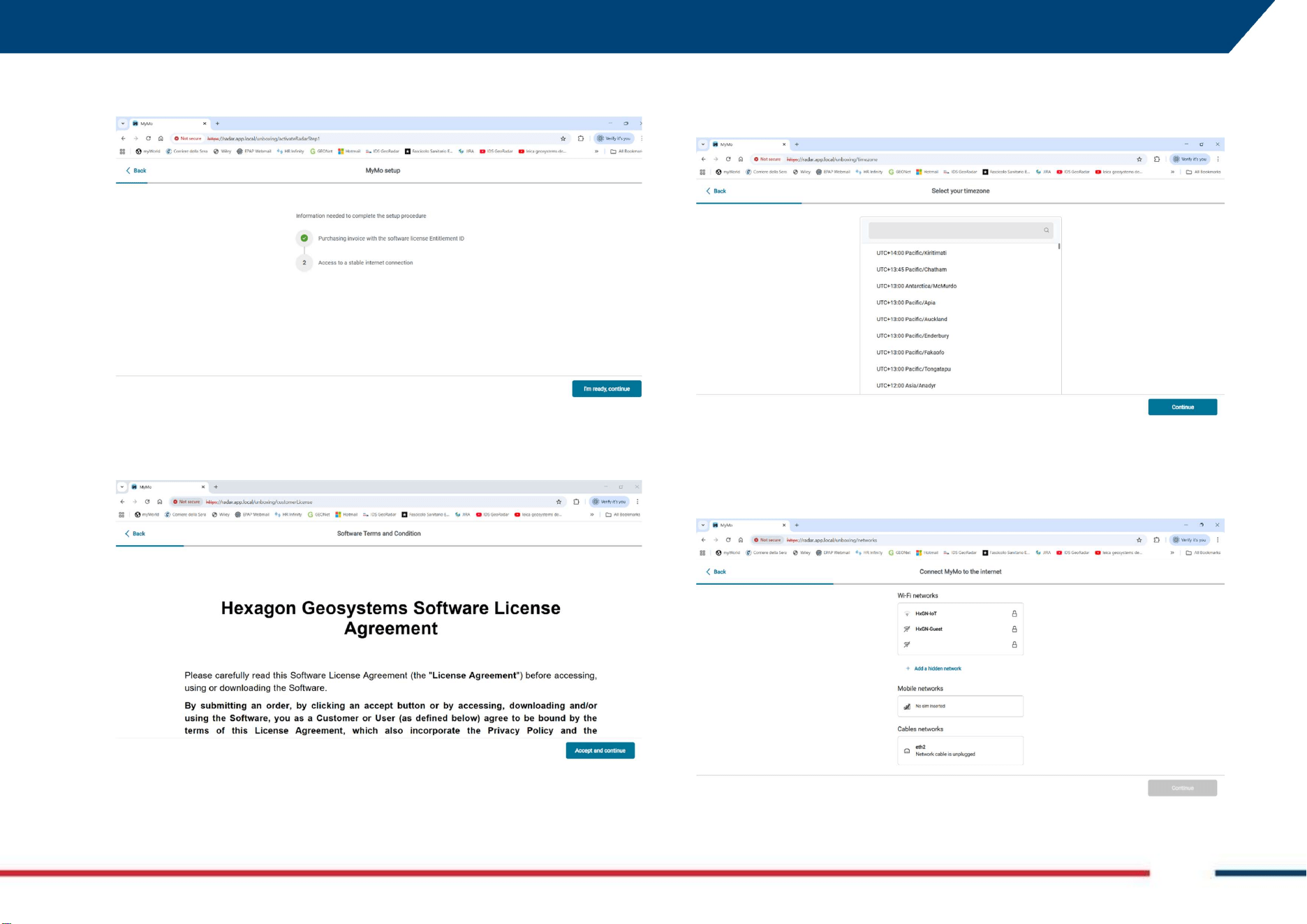
14. Enter now the EID 25-digits code included in the invoice and press
“Continue”,
15. Read the legal notice and then press on “Accept and Continue”,
16. Select now the time zone where the system is in use, and press
“Continue” (the search box may be used to search for a specific
location),
17. Connect the system to the internet by selecting the preferred WiFi
Hotspot and press “Continue”,
7 How to get started MyMo Field App Mod: MDM/011/M2 Rev 10
IDS GeoRadar Srl MNG/2025/012 Rev. 1.0 40/ 71
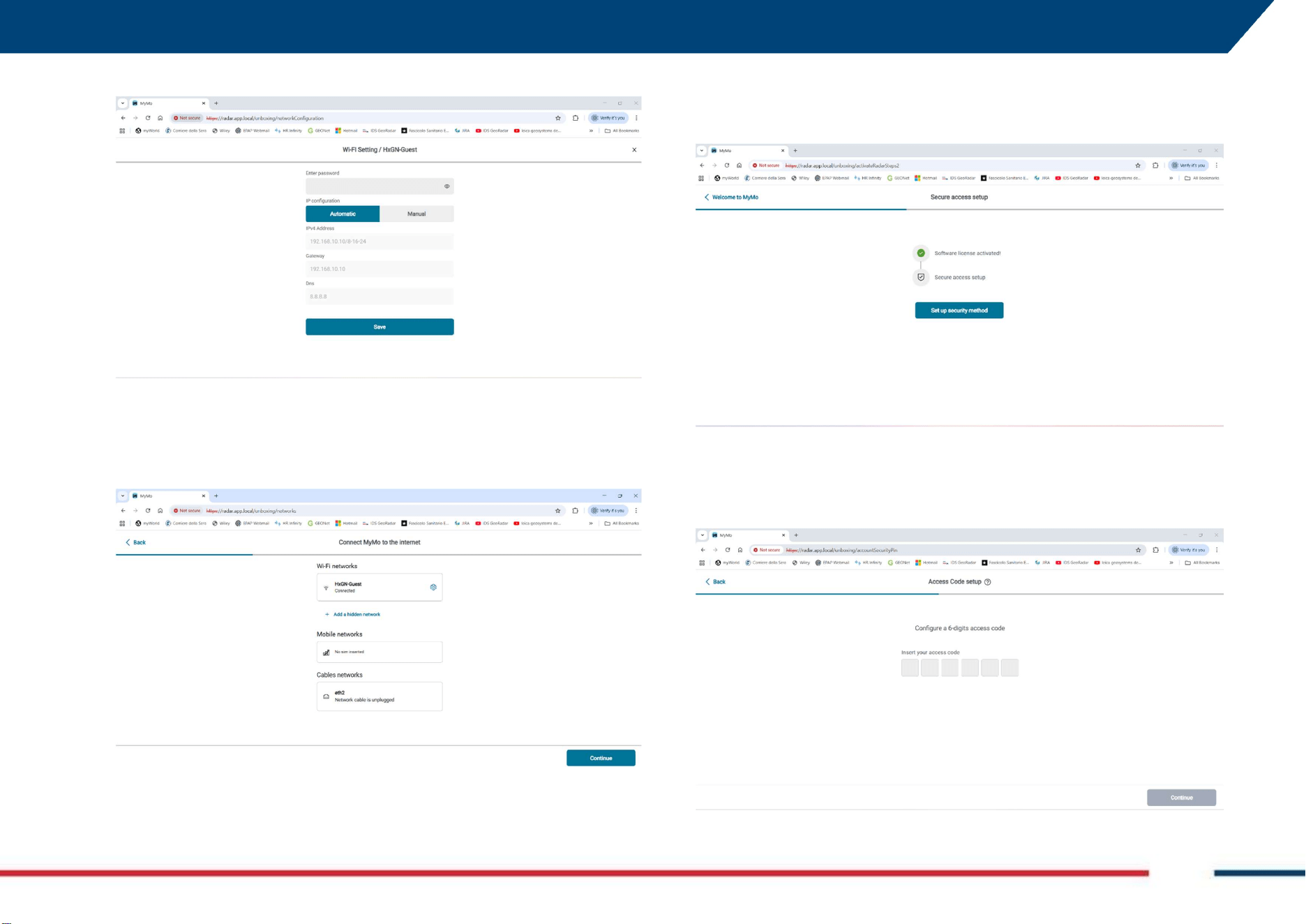
18. Enter the password and press “Save” to continue,
19. Enter EID,
20. Now press “Continue”, to proceed
21. MyMo Field App software license is now activated,
22. Configure now the 6-digit access code to be used for any future login,
and press “Continue”,