Service and Troubleshooting
DC3SQN, DC3SEN, DC4SQA, DC4SEA, DC5SEA Condensing Units.
DH4SQA, DH4SEA, DH5SEA Heat Pumps
With Refrigerant Blowers, Coils, & Accessories
RS6200301
July 2024
Pride and workmanship go into every product to provide
our customers with quality products. It is possible, however,
that during its lifetime a product may require service.
Products should be serviced only by a qualied service
technician who is familiar with the safety procedures
required in the repair and who is equipped with the proper
tools, parts, testing instruments and the appropriate service
manual. REVIEW ALL SERVICE INFORMATION IN THE
APPROPRIATE SERVICE MANUAL BEFORE
BEGINNING REPAIRS.
©2019-2024 Daikin Comfort Technologies Manufacturing, L.P.
®
Brand is a registered trademark of Maytag Corporation or its related companies and is used under license. All rights reserved.
WARNING
Do not bypass safety devices.
ONLY PERSONNEL THAT HAVE BEEN TRAINED TO INSTALL,
ADJUST, SERVICE, MAINTENANCE OR REPAIR
(HEREINAFTER, “SERVICE”) THE EQUIPMENT SPECIFIED IN
THIS MANUAL SHOULD SERVICE THE EQUIPMENT.
THIS EQUIPMENT IS NOT INTENDED FOR USE BY
PERSONS (INCLUDING CHILDREN) WITH REDUCED
PHYSICAL, SENSORY OR MENTAL CAPABILITIES, OR LACK
OF EXPERIENCE AND KNOWLEDGE, UNLESS THEY HAVE
BEEN GIVEN SUPERVISION OR INSTRUCTION CONCERNING
USE OF THE APPLIANCE BY A PERSON RESPONSIBLE FOR
THEIR SAFETY.
CHILDREN SHOULD BE SUPERVISED TO ENSURE THAT
THEY DO NOT PLAY WITH THE EQUIPMENT.
THE MANUFACTURER WILL NOT BE RESPONSIBLE FOR
ANY INJURY OR PROPERTY DAMAGE ARISING FROM
IMPROPER SUPERVISION, SERVICE OR SERVICE
PROCEDURES. IF YOU SERVICE THIS UNIT, YOU ASSUME
RESPONSIBILITY FOR ANY INJURY OR PROPERTY
DAMAGE WHICH MAY RESULT. IN ADDITION, IN
JURISDICTIONS THAT REQUIRE ONE OR MORE LICENSES
TO SERVICE THE EQUIPMENT SPECIFIED IN THIS
MANUAL, ONLY LICENSED PERSONNEL SHOULD SERVICE
THE EQUIPMENT. IMPROPER SUPERVISION, INSTALLATION,
ADJUSTMENT, SERVICING, MAINTENANCE OR REPAIR OF
THE EQUIPMENT SPECIFIED IN THIS MANUAL, OR
ATTEMPTING TO INSTALL, ADJUST, SERVICE OR REPAIR
THE EQUIPMENT SPECIFIED IN THIS MANUAL WITHOUT
PROPER SUPERVISION OR TRAINING MAY RESULT IN
PRODUCT DAMAGE, PROPERTY DAMAGE, PERSONAL
INJURY OR DEATH.
WARNING
WARNING
All maintenance staff and others working in the local area
shall be instructed on the nature of work being carried out.
Work in confined spaces shall be avoided.
WARNING
No person carrying out work in relation to a REFRIGERATING
SYSTEM which involves exposing any pipe work shall use
any sources of ignition in such a manner that it may lead to
the risk of fire or explosion. All possible ignition sources,
including cigarette smoking, should be kept sufficiently far
away from the site of installation, repairing, removing and
disposal, during which refrigerant can possibly be released
to the surrounding space. Prior to work taking place, the
area around the equipment is to be surveyed to make sure
that there are no flammable hazards or ignition risks. “No
Smoking” signs shall be displayed.

2
IMPORTANT INFORMATION
TABLE OF CONTENTS
IMPORTANT INFORMATION ..........................................2
PRODUCT IDENTIFICATION .......................................... 5
PRODUCT DESIGN .........................................................9
SYSTEM OPERATION ...................................................12
SERVICING .....................................................................15
CHECKING VOLTAGE .............................................15
CHECKING WIRING ................................................ 15
CHECKING THERMOSTAT AND WIRING ............ 15
INDOOR BLOWER MOTOR ....................................15
RESISTANCE HEATERS ........................................16
CHECKING TRANSFORMER AND CONTROL
CIRCUIT ....................................................................16
CHECKING CONTRACTOR AND/OR RELAYS ....16
CHECKING CONTACTOR CONTACTS .................16
CHECKING FAN RELAY CONTACTS ....................17
CHECKING HIGH PRESSURE CONTROL ..........17
CHECKING LOW PRESSURE CONTROL ............18
COPELAND CORESENSE™ DIAGNOSTICS -
3-WIRE MODULE ..................................................... 18
CHECKING CAPACITOR ........................................23
RESISTANCE CHECK USING A DIGITAL
MULTI-METER .........................................................23
CHECK FOR ANALOG METER ..............................23
CAPACITANCE CHECK USING A DIGITAL MULTI-
METER (IN CAPACITANCE MODE) ....................... 23
CAPACITOR, START ...............................................23
TESTING A RUN CAPACITOR UNDER LOAD ...... 24
REFRIGERANT DETECTION SYSTEM (RDS) .....24
CHECKING HIGH EFFICIENCY MOTORS ...........26
EEM BLOWER REPLACEMENT ............................27
CHECKING COMPRESSOR ................................... 28
RESISTANCE TEST ...............................................28
GROUND TEST ........................................................ 29
UNLOADER TEST PROCEDURE .........................29
OPERATION TEST .................................................30
TESTING CRANKCASE HEATER .........................30
CHECKING REVERSING VALVE AND
SOLENOID ...............................................................30
TROUBLESHOOTING THE REVERSING VALVE
FOR ELECTRICAL FAILURE .................................. 31
TROUBLEHSOOTING MECHANICAL FAILURES
ON A REVERSING VALVE BY PRESSURE ..........31
TROUBLESHOOITNG MECHANICAL FAILURES
ON A REVERSING VALVE BY TEMPERATURE ... 31
TESTING DEFROST CONTROL ............................31
TESTING DEFROST THERMOSTAT .....................31
CHECKING HEATER ELEMENTS ..........................32
CHECKING HEATER LIMIT CONTROL(S) ............33
CHECKING HEATER FUSE LINK ..........................33
REFRIGERATION REPAIR PRACTICE .................33
BRAZING MATERIALS ............................................34
STANDING PRESSURE TEST (RECOMMENDE
BEFORE SYSTEM EVACUATION .......................... 34
LEAK TESTING (NITROGEN OR NITROGEN-
TRACED) ..................................................................34
SYSTEM EVACUATION ..........................................34
DEEP VACUUM METHOD .....................................35
TRIPLE RVACUATION METHOD ...........................35
CHARGING ...............................................................36
FINAL CHARGE ADJUSTMENT .............................37
FIXED ORFICES ...................................................... 39
EXPANSION VLAVE SYSTEM ....................................
SUPERHEAT ADJUSTMENT ..................................39
HEAT PUMP - HEATING CYCLE .........................40
CHECKING COMPRESSOR EFFICIENCY ...........40
CHECKING RESTRICTED LIQUID LINE...............41
OVERCHARGE OF REFRIGERANT ...................... 41
NON-CONDENSABLES ..........................................41
CHECKING COMPRESSOR EFFICIENCY ...........41
COMPRESSOR BURNOUT ....................................41
SUCTION LINE DRIER CLEAN-UP METHOD ......42
REFRIGERANT PIPING ..........................................42
DUCT STATIC PRESSURES ..................................42
PERIODIC MAINTENANCE ....................................43
CLEANING ALUMINUM COILS ..............................44
SYSTEM SERVICE AND DECOMMISSIONING ...44
LABELLING OF EQUIPMENT .............................45
TROUBLESHOOTING ...................................................46
WIRING DIAGRAMS ......................................................53
3
IMPORTANT INFORMATION
IMPORTANT NOTICES
RECOGNIZE SAFETY SYMBOLS, WORDS AND
LABELS
WARNING
To prevent the risk of property damage, personal injury, of
death, do not store combustible materials or use gasoline
or other flammable liquids or vapors in the vicinity of this
appliance.
WARNING
HIGH VOLTAGE
Disconnect ALL power before servicing or
installing this unit. Multiple power sources
may be present. Failure to do so may cause
property damage, personal injury or death.
WARNING
This unit should not be connected to, or used in conjunction
with, any devices that are not design certified for use
with this unit or have not been tested and approved by the
manufacturer. Serious property damage or personal injury,
reduced unit performance and/or hazardous conditions may
result from the use of devices that have not been approved
or certified by the manufacturer.
SAFE REFRIGERANT HANDLING
While these items will not cover every conceiv-
able situation, they should serve as a useful
guide.
WARNING
Refrigerants are heavier than air. They can “push out” the
oxygen in your lungs or in any enclosed space. To avoid
possible difficulty in breathing or death:
• Never purge refrigerant into an enclosed room or space.
By law, all refrigerant must be reclaimed.
• If an indoor leak is suspected, thoroughly ventilate the
area before beginning work.
• Liquid refrigerant can be very cold. To avoid possible
frostbite or blindness, avoid contact with refrigerant
and wear gloves and goggles. If liquid refrigerant does
contact your skin or eyes, seek medical help immediately.
• Always follow EPA regulations. Never burn refrigerant,
as poisonous gas will be produced.
WARNING
To avoid possible injury, explosion or death, practice safe
handling of refrigerants.
WARNING
The compressor POE oil for R-32 units is extremely
susceptible to moisture absorption and could cause
compressor failure. Do not leave system open to atmosphere
any longer than necessary for installation.
WARNING
To avoid possible explosion:
• Never apply flame or steam to a refrigerant cylinder. If
you must heat a cylinder for faster charging, partially
immerse it in warm water.
• Never fill a cylinder more than 80% full of liquid
refrigerant.
• Never add anything other than R-32 to an R-32 cylinder
or R-410A to an R-410A cylinder. The service equipment
used must be listed or certified for the type of
refrigerant used.
• Store cylinders in a cool, dry place. Never use a cylinder
as a platform or a roller.
WARNING
To avoid possible explosion, use only returnable (not
disposable) service cylinders when removing refrigerant
from a system.
• Ensure the cylinder is free of damage which could lead
to a leak or explosion.
• Ensure the hydrostatic test date does not exceed 5
years.
Ensure the pressure rating meets or exceeds 400 lbs.
When in doubt, do not use cylinder.
OUTSIDE THE U.S., call 1-713-861-2500.
(Not a technical assistance line for dealers.) Your telephone company will bill you for the call.

4
The manual contains specic information for service
personnel
Checks to the area
Prior to beginning work on systems containing
FLAMMABLE REFRIGERANTS, safety checks are
necessary to ensure that the risk of ignition is minimized.
For repair to the REFRIGERATING SYSTEM the following
procedures must be completed prior to conducting work on
the system.
Work procedure
Work shall be undertaken under a controlled procedure so
as to minimize the risk of a ammable gas or
vapor being present while the work is being performed.
General work area
All maintenance sta and others working in the local area
shall be instructed on the nature of work being
carried out. Work in conned spaces shall be avoided.
Checking for presence of refrigerant
The area shall be checked with an appropriate refrigerant
detector prior to and during work, to ensure the
technician is aware of potentially toxic or ammable
atmospheres. Ensure that the leak detection
equipment being used is suitable for use with all applicable
refrigerants, i.e. non-sparking, adequately
sealed or intrinsically safe.
Presence of re extinguisher
If any hot work is to be conducted on the refrigerating
equipment or any associated parts, appropriate re
extinguishing equipment shall be available to hand. Have
a dry powder or CO2 re extinguisher adjacent to the
charging area.
No ignition sources
No person carrying out work in relation to a
REFRIGERATING SYSTEM which involves exposing
any pipe work shall use any sources of ignition in such a
manner that it may lead to the risk of re or explosion. All
possible ignition sources, including cigarette smoking,
should be kept suciently far away from the site of
installation, repairing, removing and disposal, during which
refrigerant can possibly be released to the surrounding
space. Prior to work taking place, the area around the
equipment is to be surveyed to make
sure that there are no ammable hazards or ignition risks.
“No Smoking” signs shall be displayed.
Checks to the refrigerating equipment
Where electrical components are being changed, they
shall be t for the purpose and to the correct specication.
At all times the manufacturer’s maintenance and service
guidelines shall be followed. If in doubt, consult the
manufacturer’s technical department for assistance.
When replacing electrical components “intrinsically safe
components” must be used as replacements.
The following checks shall be applied to installations using
FLAMMABLE REFRIGERANTS:
• the actual REFRIGERANT CHARGE is in accordance
with the room size within which the refrigerant
containing parts are installed;
• the ventilation machinery and outlets are operating
adequately and are not obstructed;
• if an indirect refrigerating circuit is being used, the
secondary circuit shall be checked for the presence of
refrigerant;
• marking to the equipment continues to be visible and
legible. Markings and signs that are illegible shall be
corrected;
• refrigerating pipe or components are installed in a
position where they are unlikely to be exposed to any
substance which may corrode refrigerant containing
components, unless the components are constructed
of materials which are inherently resistant to being
corroded or are suitably protected against being so
corroded.
Checks to electrical devices
Repair and maintenance to electrical components shall
include initial safety checks and component
inspection procedures. If a fault exists that could
compromise safety, then no electrical supply shall be
connected to the circuit until it is satisfactorily dealt with. If
the fault cannot be corrected immediately but it
is necessary to continue operation, an adequate temporary
solution shall be used. This shall be reported
to the owner of the equipment so all parties are advised.
Initial safety checks shall include:
• that capacitors are discharged: this shall be done in a
safe manner to avoid possibility of sparking;
• that no live electrical components and wiring are
exposed while charging, recovering or purging the
system;
• that there is continuity of earth bonding.
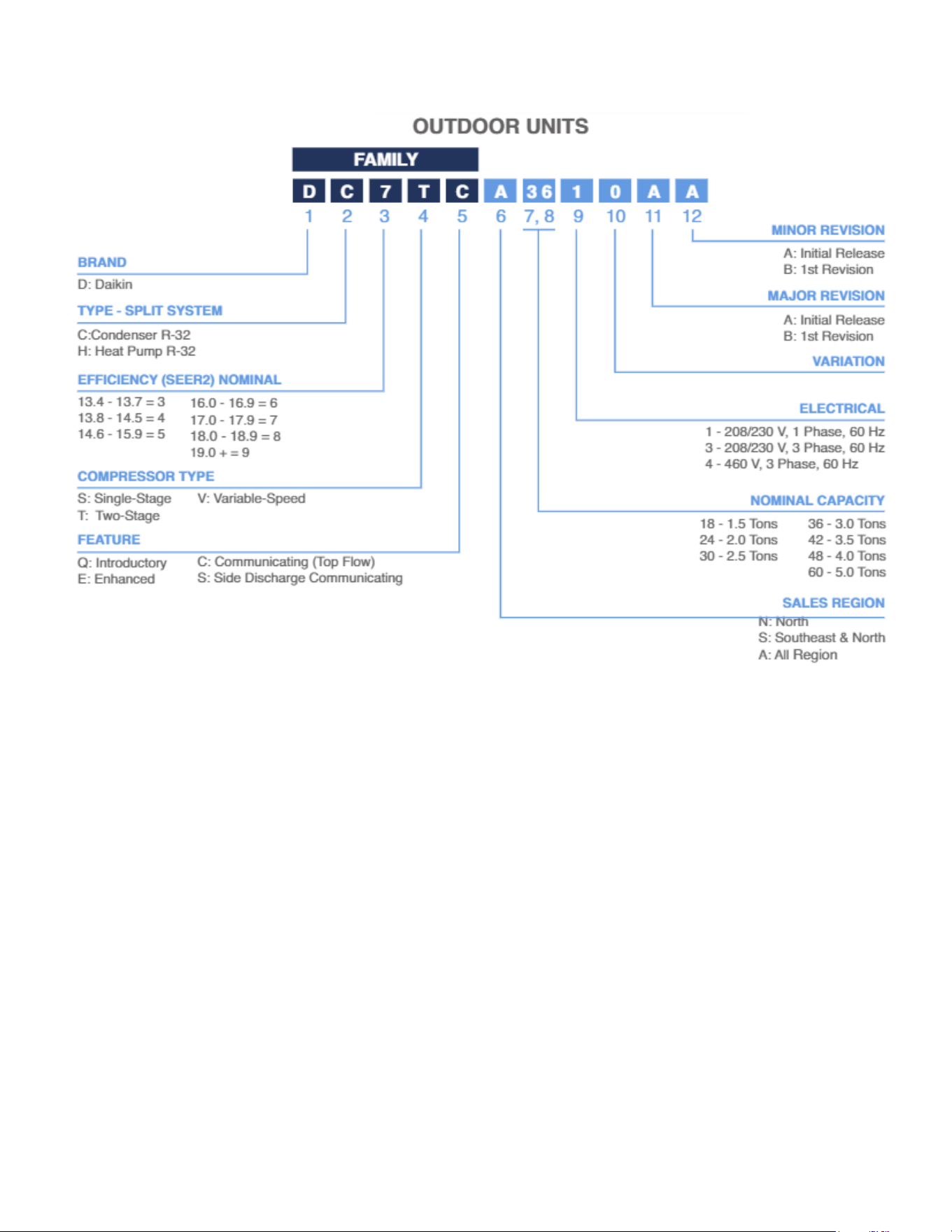
5
PRODUCT IDENTIFICATION NOMENCLATURE
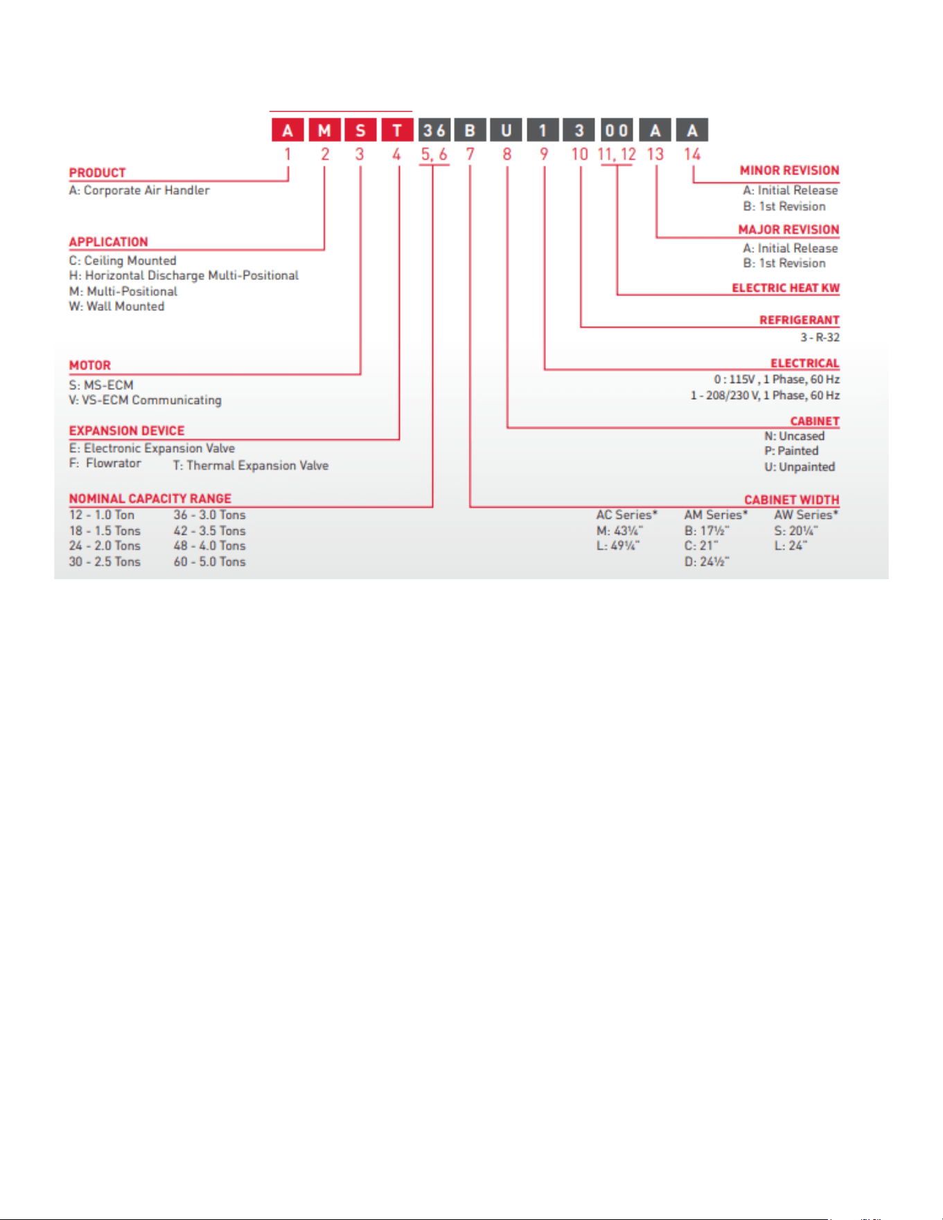
6
PRODUCT IDENTIFICATION NOMENCLATURE
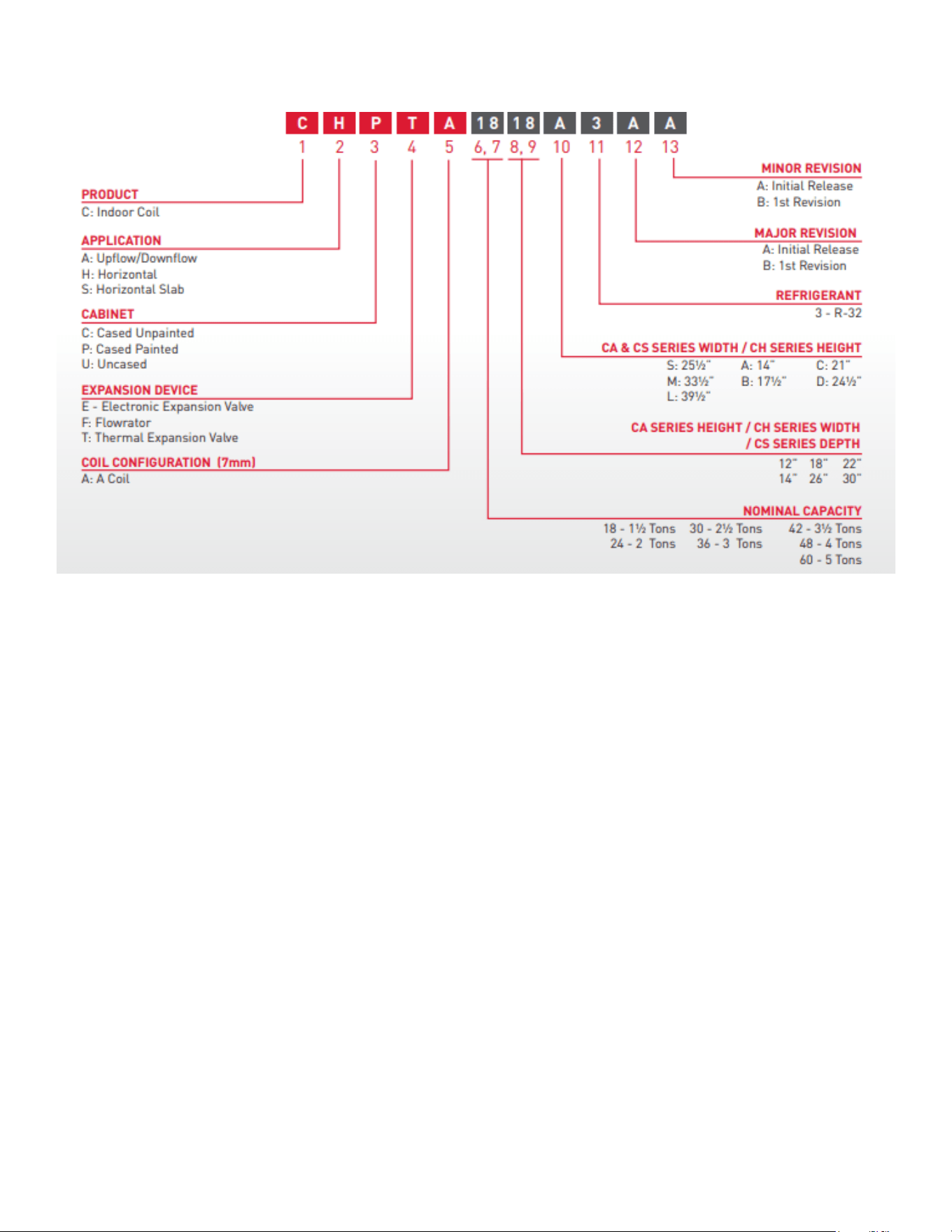
7
PRODUCT IDENTIFICATION NOMENCLATURE
8
PRODUCT IDENTIFICATION
Model/Rev
Description
DC3SQN* * 10AA Ini ti al rel ease of Dai ki n13.4-13.7 SEER2 AC R32 (North)
DC4SQA* * 10AA Ini ti al rel ease of Dai ki n13.8-14.5 SEER2 AC R32 ( Al l Regi ons)
DC4SEA* * 10AA Ini ti al rel ease of Dai ki n 13.8-14.5 SEER2 AC R32 (North)
DC5SEA* * 10AA Ini ti al rel ease of Dai ki n14.6-15.9 SEER2 AC R32 ( Al l Regi ons)
DH4SQA* * 10AA Ini ti al rel ease of Dai ki n 13.8-14.5 SEER2 HP R32 ( Al l Regi ons)
DH4SEA* * 10AA Ini ti al rel ease of Dai ki n 13.8-14.5 SEER2 HP R32 ( Al l Regi ons)
DH5SEA* * 10AA Ini ti al rel ease of Dai ki n 14.6-15.9 SEER2 HP R32 ( Al l Regi ons)
Model/Rev Description
ACSF****13**AA Initial release of Corporate Ceiling Mount R32 Air Handler
AWSF/T****13**AA Initial release of Corporate Wall Mount R32 Air Handler
AMST* * * U1300AA Initial release of Corporate Multi-position R32 Air Handler
Model/Rev Description
CAPTA*****3AA Initial release of Corporate Multi-Position R32 Evaporator Coil
CAUFA*****3AA Initial release of Corporate Uncased R32 Evaporator Coil
CHPTA*****3AA Initial release of Corporate Multi-Position R32 Horizontal Evaporator Coil
CSCT****3AA Initial release of Corporate Horizontal Slab R32 Evaporator Coil
DAIKIN R32 SINGLE STAGE A-BASE UNIT CONDENSERS
CORPORATE R32 AI R HANDLER
CORPORATE CASED AND UNCASED COILS
Model/Rev Description
CAPFA*****3AA Initial release of Corporate Multi-Position R32 Evaporator Coil
CAPTA*****3AA Initial release of Corporate Multi-Position R32 Evaporator Coil
CAUTA*****3AA Initial release of Corporate Uncased R32 Evaporator Coil
CHPTA*****3AA Initial release of Corporate Multi-Position R32 Horizontal Evaporator Coil
CSCT****3AA Initial release of Corporate Horizontal Slab R32 Evaporator Coil
Model/Rev Description
AWST****13**AA Initial release of Corporate Wall Mount R32 Air Handler
AMST* * * U1300AA Initial release of Corporate Multi-position R32 Air Handler
CORPORATE CASED AND UNCASED COILS
CORPORATE R32 AI R HANDLER
9
PRODUCT DESIGN
This section gives a basic description of cooling unit
operation, its various components and their basic
operation. Ensure your system is properly sized for heat
gain and loss according to methods of the Air Conditioning
Contractors Association (ACCA) or equivalent.
Condensing Unit
The condenser air is pulled through the condenser coil
by a direct drive propeller fan. This condenser air is then
discharged out of the top of the cabinet. These units are
designed for free air discharge, so no additional resistance,
like duct work, shall be attached.
The suction and liquid line connections on present models
are of the sweat type for eld piping with refrigerant type
copper. Front seating valves are factory installed to accept
the eld run copper. The total refrigerant charge for a
normal installation is factory installed in the condensing
unit.
New R32 models are available in 1 1/2 through 5 ton sizes
and use refrigerant. They are designed for 208/230 volt
single phase applications.
DC4SEA, DC5SEA, DH4SEA and DH5SEA R32 model
units use the Copeland YP**K1 R32 scroll compressors
which are specically designed for R32 refrigerant. These
units also have Copeland® ComfortAlert diagnostics.
DC3SQN, DC4SQA and DH4SQA use a mix of Scroll
and Energy Ecient compressors model units use a
mix of Scroll and Energy Ecient compressors which
are specically designed for refrigerant. There are
several design characteristics which are dierent from
the traditional reciprocating and/or scroll compressors.
“Ultratech” Series scroll compressors will not have a
discharge thermostat. Some of the early model scroll
compressors required discharge thermostat.
R32 compressors use “POE” or polyolester oil which is
NOT compatible with mineral oil based lubricants like 3GS.
“POE” oil must be used if additional oil is required.
The coils are designed for upow and counterow
applications. The coils are designed for horizontal
applications.
AMST
Multi-Position Air Handler
These one-piece multi-position air handlers are used with
and are available in 2 to 5 ton sizes with optional 3 kW to
25kW electric heat kits available for eld installation. Units
use an EEM blower motor and are compatible with heat
pumps and cooling applications.
This appliance can be installed in the vertical or left
horizontal position without modication. The horizontal right
and downow positions require product modication. This
product is designed for zero inches (0 inches) clearance;
however, adequate access for service or replacement
must be considered without removing permanent structure.
This unit can be installed on a platform when deemed
necessary.
In an attic installation a secondary drain pan must be
provided by the installer and placed under the entire unit
with a separate drain line properly sloped and terminated
in an area visible to the owner. This secondary drain pan
is required in the event that there is a leak or main drain
blockage. Closed cell insulation should be applied to the
drain lines in unconditioned spaces where sweating may
occur.
NOTE: Single piece air handlers are factory-sealed to
achieve a 2% or less leakage rate at 1.0” water gauge
external duct static pressure.
R32 model numbers that use two stage compressors series
split system units use a two-stage scroll compressor. The
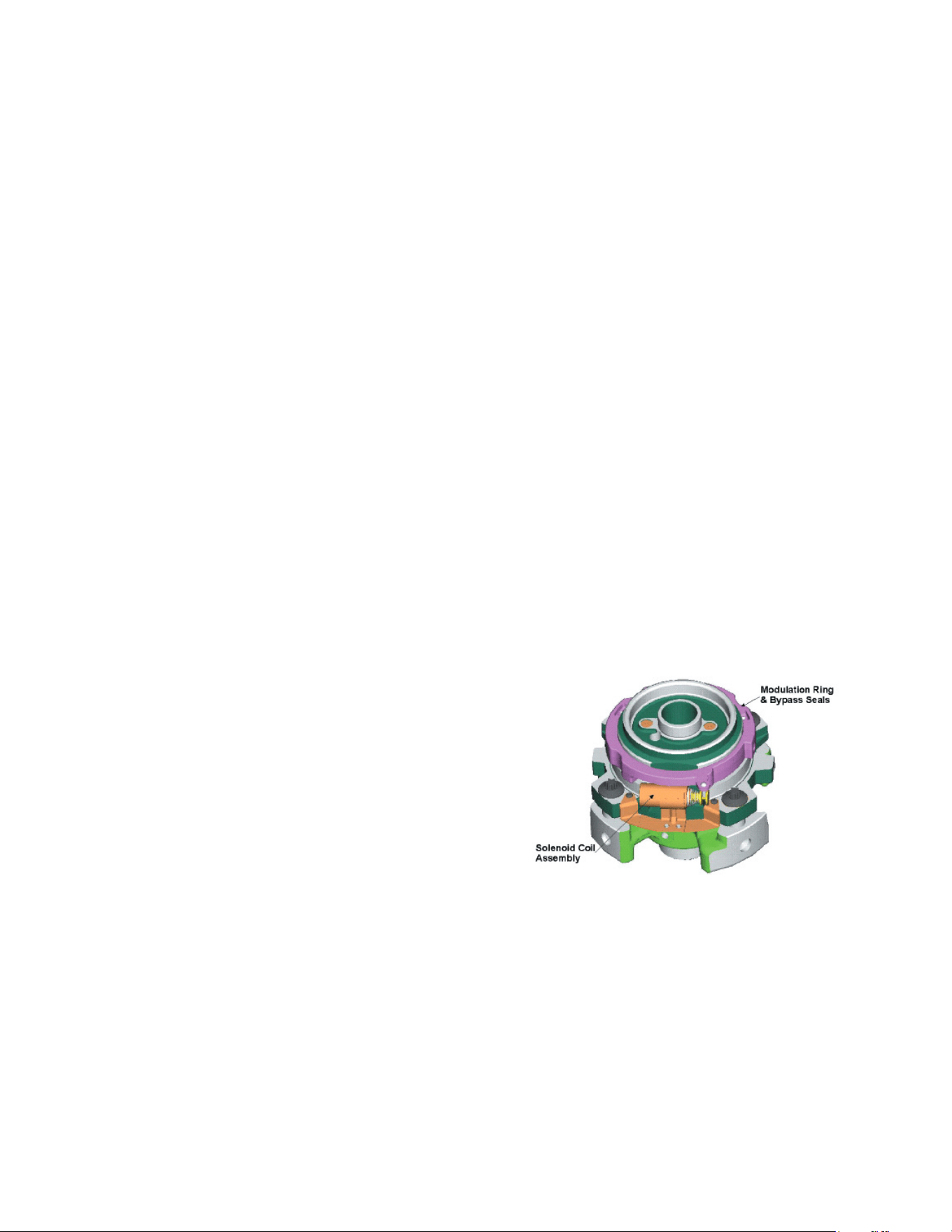
two-step modulator has an internal unloading mechanism
that opens a bypass port in the rst compression pocket,
eectively reducing the displacement of the scroll. The
opening and closing of the bypass port is controlled by an
internal electrically operated solenoid.
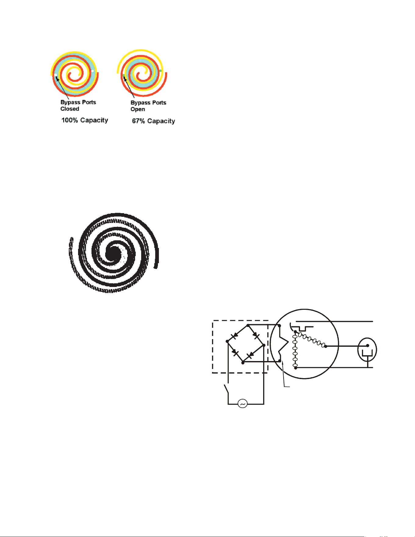
The new Copeland model numbers YPS**K1 R32
compressors two-step modulated scroll uses a single step
of unloading to go from full capacity to approximately 67%
capacity. A single speed, high eciency motor continues
to run while the scroll modulates between the two capacity
steps.
10
PRODUCT DESIGN
FIGURE A
A scroll is an involute spiral which, when matched with a
mating scroll form as shown, generates a series of crescent
shaped gas pockets between the two members.
During compression, one scroll remains stationary (xed
scroll) while the other form (orbiting scroll) is allowed to
orbit (but not rotate) around the rst form.
As this motion occurs, the pockets between the two forms
are slowly pushed to the center of the two scrolls while
simultaneously being reduced in volume. When the pocket
reaches the center of the scroll form, the gas, which is now
at a high pressure, is discharged out of a port located at the
center.
During compression, several pockets are being
compressed simultaneously, resulting in a very smooth
process. Both the suction process (outer portion of the
scroll members) and the discharge process (inner portion)
are continuous.
Some design characteristics of the Compliant Scroll
compressor are:
• Compliant Scroll compressors are more tolerant of
liquid refrigerant.
NOTE: Even though the compressor section of a Scroll
compressor is more tolerant of liquid refrigerant,
continued oodback or ooded start conditions may
wash oil from the bearing surfaces causing premature
bearing failure.
• “Ultratech” Series scroll compressors use “POE” or
polyolester oil which is NOT compatible with mineral
oil based lubricants like 3GS. “POE” oil must be used
if additional oil is required.
• Compliant scroll compressors perform “quiet”
shutdowns that allow the compressor to restart
immediately without the need for a time delay. This
compressor will restart even if the system has not
equalized.
NOTE: Operating pressures and amp draws may
dier from standard reciprocating compressors.
This information can be found in the unit’s Technical
Information Manual.
Capacity Control - Legacy Models
During the compression process, there are several pockets
within the scroll that are compressing gas. Modulation is
achieved by venting a portion of the gas in the rst suction
pocket back to the low side of the compressor thereby
reducing the eective displacement of the compressor.
See Figure A. Full capacity is achieved by blocking these
vents, increasing the displacement to 100%. A solenoid in
the compressor, controlled by an external 24-volt ac signal,
moves the slider ring that covers and uncovers these vents.
The vent covers are arranged in such a manner that the
compressor operates somewhere around 67% capacity
when the solenoid is not energized and 100% capacity
when the solenoid is energized. The loading and unloading
of the two step scroll is done “on the y” without shutting
o the motor between steps. See Figure B below. The
unloaded mode default was chosen for two reasons:
Molded Plug w/
Rectifier
24 Vac
Line
Line
Run Capacitor
C
R
S
Internal Unloader
Coil
FIGURE B
1. It is expected that the majority of run hours will be in
the low capacity, unloaded mode.
2. It allows a simple two-stage thermostat to control
capacity through the second stage in both cooling and
possibly heating if desired.

11
PRODUCT DESIGN
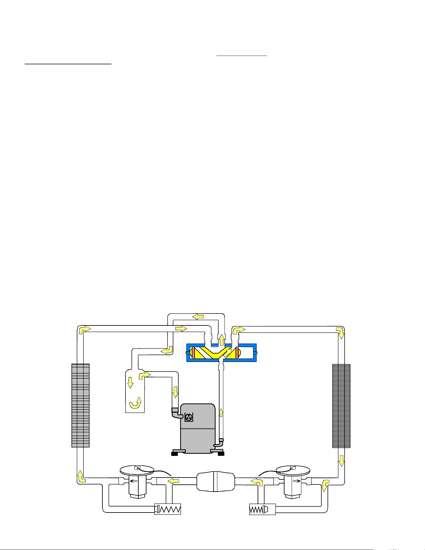
Unloader Solenoid
A nominal 24-volt direct current coil activates the internal
unloader solenoid. The input control circuit voltage must be
18 to 28 volt ac. The coil power requirement is 20 VA. The
external electrical connection is made with a molded plug
assembly. This plug is connected to the Comfort Alert™
or CoreSense™ Module (dependent upon which module
you are using) which contains a full wave rectier to supply
direct current to the unloader coil.
12
SYSTEM OPERATION
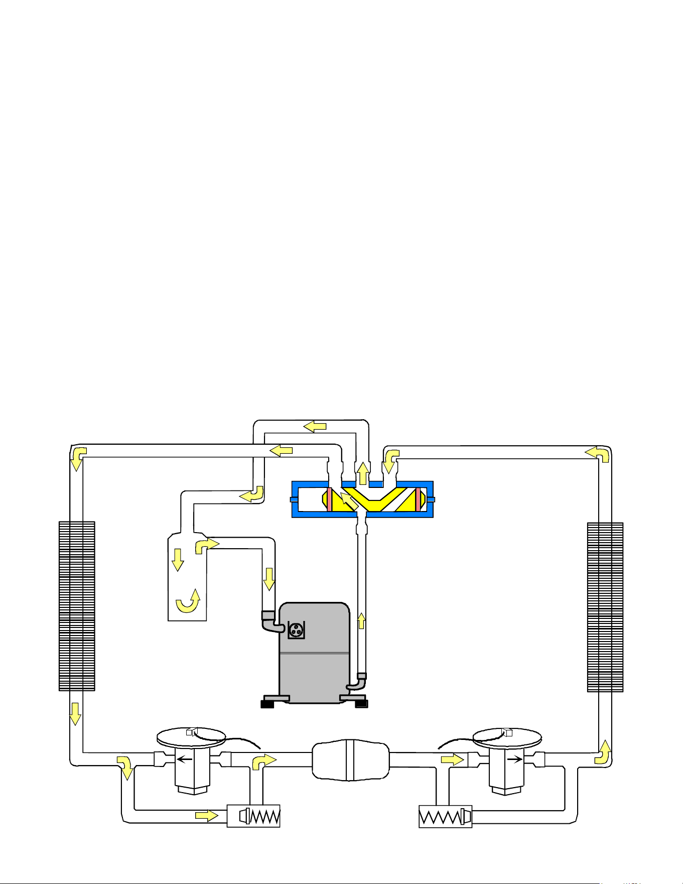
Cooling Cycle
For legacy room thermostat: When the room thermostat
calls for cool, the contacts of the room thermostat close
making terminals R to Y1 & G (if thermostat calls for low
stage cool), or R to Y1, Y2 & G (if thermostat calls for high
stage cool), the low voltage circuit of the transformer is
completed. Current now ows through the magnetic holding
coils of the compressor contactor (CC) and fan relay (RFC).
If thermostat calls for high stage cool, the microprocessor
on the UC board will also energize the compressor high
stage solenoid to run the compressor at full capacity.
This draws in the normally open contact CC, starting the
compressor and condenser fan motors in either low or high
stage depending on the thermostat’s demand. At the same
time, contacts RFC close, starting the indoor fan motor.
When the thermostat is satised, it opens its contacts,
breaking the low voltage circuit, causing the compressor
contactor and indoor fan relay to open, shutting down the
system.
If the room thermostat fan selector switch should be set
on the “on” position, then the indoor blower would run
continuously rather than cycling with the compressor.
R32 heat pump models energize the reversing valve
thorough the “O” circuit in the room thermostat. Therefore,
the reversing valve remains energized as long as the
thermostat subbase is in the cooling position. The only
exception to this is during defrost.
For heat pumps, during cooling cycle the reversing valve is
energized as the room thermostat closes “O” terminal to R
and the microprocessor on the UC board responds to such
a condition by energizing the solenoid coil on the reversing
valve.
Defrost Cycle
The defrosting of the outdoor coil is jointly controlled by the
defrost control board and the defrost thermostat.
Solid State Defrost Control
During operation the power to the circuit board is controlled
by a temperature sensor, which is clamped to a return
bend (3/8” coils) or a feeder tube (5 mm coils) entering the
outdoor coil. Defrost timing periods of 30, 60, or 90 minutes
may be selected by connecting the circuit board jumper
to 30, 60, or 90 respectively. Accumulation of time for
the timing period selected starts when the sensor closes
(approximately 31°F), and when the room thermostat
calls for heat. At the end of the timing period, the unit’s
defrost cycle will be initiated provided the sensor remains
closed. When the sensor opens (approximately 75°F), the
defrost cycle is terminated and the timing period is reset.
If the defrost cycle is not terminated due to the sensor
temperature, a ten minute override interrupts the unit’s
defrost period. The new upgraded defrost control has a 12
minute override interrupt.
Indoor
Coil
Accumulator
Bi-Flow
Filter Dryer
Outdoor
Coil
Thermostatic
Expansion
Valve
Check Valve
Reversing Valve
(De-Energized)
Indoor
Coil
Accumulator
Bi-Flow
Filter Dryer
Outdoor
Coil
Thermostatic
Expansion
Valve
Check Valve
Reversing Valve
(Energized)
Cooling Cycle
13
SYSTEM OPERATION
Heating Cycle
The reversing valve on the models is energized in the
cooling cycle through the “O” terminal on the room
thermostat.
These models have a 24 volt reversing valve coil. When the
thermostat selector switch is set in the cooling position, the
“O” terminal on the thermostat is energized all the time.
Care must be taken when selecting a room thermostat.
Refer to the installation instructions shipped with the
product for approved thermostats.
When the room thermostat calls for heat, the contacts of
the room thermostat close making terminals R to Y & G,
the low voltage circuit of the transformer is completed.
Current now ows through the magnetic holding coils of the
compressor contactor (CC) and fan relay (RFC).
This draws in the normally open contact CC, starting the
compressor condenser fan motors. At the same time,
contacts RFC close, starting the indoor fan motor.
When the thermostat is satised, it opens its contacts,
breaking the low voltage circuit, causing the compressor
contactor and indoor fan relay to open, shutting down the
system.
If the room thermostat fan selector switch should be set
to the “on” position, then the indoor blower would run
continuously rather than cycling with the compressor.
When the thermostat is satised, appropriate commands
are sent to the UC control. The compressor relay and
outdoor fan relay is de-energized. The compressor high
stage solenoid is de-energized if it was energized. The UC
control sends an appropriate command to the indoor unit to
de-energize the indoor blower motor.
Indoor
Coil
Accumulator
Bi-Flow
Filter Dryer
Outdoor
Coil
Thermostatic
Expansion
Valve
Check Valve
Reversing Valve
(De-Energized)
Indoor
Coil
Accumulator
Bi-Flow
Filter Dryer
Outdoor
Coil
Thermostatic
Expansion
Valve
Check Valve
Reversing Valve
(Energized)
Heating Cycle
14
SYSTEM OPERATION
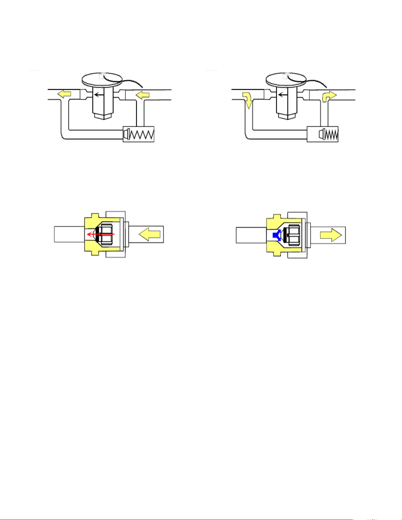
Expansion Valve/Check Valve Assembly In Cooling
Operation
Most expansion valves used in current Amana® Brand Heat Pump products use an internally checked expansion valve.
This type of expansion valve does not require an external check valve as shown above.
Restrictor Orice Assy in Cooling Operation
In the cooling mode, the orice is pushed into its seat,
forcing refrigerant to ow through the metered hole in the
center of the orice.
Expansion Valve/Check Valve Assembly In Heating
Operation
Restrictor Orice Assy in Heating Operation
In the heating mode, the orice moves back o its seat
allowing refrigerant to ow unmetered around the outside of
the orice.
15
SERVICING
Checking Voltage
1. Remove outer case, control panel cover, etc., from unit
being tested.
With power ON:
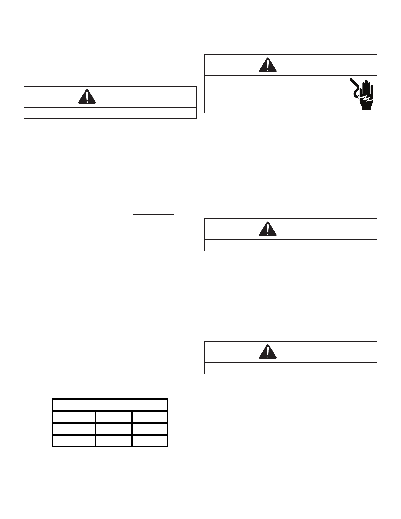
WARNING
Line voltage now present.
2. Using a voltmeter, measure the voltage across
terminals L1 and L2 of the contactor for the condensing
unit or at the eld connections for the air handler or
heaters.
3. No reading - indicates open wiring, open fuse(s) no
power or etc., from unit to fused disconnect service.
Repair as needed.
4. With ample voltage at line voltage connectors, energize
the unit.
5. Measure the voltage with the unit starting and
operating, and determine the unit Locked Rotor
Voltage.
NOTE: If checking heaters, be sure all heating elements
are energized.
Locked Rotor Voltage is the actual voltage available at
the compressor during starting, locked rotor, or a stalled
condition. Measured voltage should be above minimum
listed in chart below.
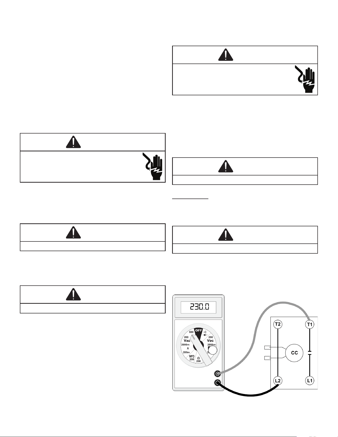
To measure Locked Rotor Voltage attach a voltmeter to the
run "R" and common "C" terminals of the compressor, or to
the T1 and T2 terminals of the contactor. Start the unit and
allow the compressor to run for several seconds, then shut
down the unit. Immediately attempt to restart the unit while
measuring the Locked Rotor Voltage.
6. Locked rotor voltage should read within the voltage
tabulation as shown. If the voltage falls below the
minimum voltage, check the line wire size. Long runs of
undersized wire can cause low voltage. If wire size is
adequate, notify the local power company in regard to
either low or high voltage.
Unit Supply Voltage
Voltage Min. Max
208/230
197 253
460 414
506
NOTE: When operating electric heaters on voltages
other than 240 volts, refer to the System Operation
section on electric heaters to calculate temperature
rise and air ow. Low voltage may cause insucient
heating.
Checking Wiring
WARNING
High Voltage!
Disconnect all power before servicing or
installing. Multiple power sources may be present.
Failure to do so may cause property damage,
personal injury or death.
1. Check wiring visually for signs of overheating,
damaged insulation and loose connections.
2. Use an ohmmeter to check continuity of any suspected
open wires.
3. If any wires must be replaced, replace with comparable
gauge and insulation thickness.
Checking Thermostat And Wiring
Thermostat Wiring: The maximum wire length for 18 AWG
thermostat wire is 100 feet.
Thermostat Wiring
WARNING
Line voltage now present.
With power ON, thermostat calling for cooling
1. Use a voltmeter to check for 24 volts at thermostat
wires C and Y in the condensing unit control panel.
2. No voltage indicates trouble in the thermostat, wiring or
external transformer source.
3. Check the continuity of the thermostat and wiring.
Repair or replace as necessary.
Indoor Blower Motor
With power ON:
WARNING
Line voltage now present.
1. Set fan selector switch at thermostat to “ON” position.
2. With voltmeter, check for 24 volts at wires C and G.
3. No voltage indicates the trouble is in the thermostat or
wiring.
4. Check the continuity of the thermostat and wiring.
Repair or replace as necessary.
16
SERVICING
Resistance Heaters
1. Set room thermostat to a higher setting than room
temperature so both stages call for heat.
2. With voltmeter, check for 24 volts at each heater relay.
3. No voltage indicates the trouble is in the thermostat or
wiring.
4. Check the continuity of the thermostat and wiring.
Repair or replace as necessary.
NOTE: Consideration must be given to how the heaters
are wired (O.D.T. and etc.). Also safety devices must be
checked for continuity.
Checking Transformer And Control Circuit
WARNING
High Voltage!
Disconnect all power before servicing or
installing. Multiple power sources may be present.
Failure to do so may cause property damage,
personal injury or death.
A step-down transformer (208/240 volt primary to 24 volt
secondary) is provided with each indoor unit. This allows
ample capacity for use with resistance heaters. The outdoor
sections do not contain a transformer (see note below).
WARNING
Disconnect ALL power before servicing.
1. Remove control panel cover, or etc., to gain access to
transformer.
With power ON:
WARNING
Line voltage now present.
2. Using a voltmeter, check voltage across secondary
voltage side of transformer (R to C).
3. No voltage indicates faulty transformer, bad wiring, or
bad splices.
4. Check transformer primary voltage at incoming line
voltage connections and/or splices.
5. If line voltage available at primary voltage side of
transformer and wiring and splices good, transformer is
inoperative. Replace.
Checking Contactor And/Or Relays
WARNING
High Voltage!
Disconnect all power before servicing or
installing. Multiple power sources may be present.
Failure to do so may cause property damage,
personal injury or death.
The compressor contactor and other relay holding coils are
wired into the low or line voltage circuits. When the control
circuit is energized, the coil pulls in the normally open
contacts or opens the normally closed contacts. When the
coil is de-energized, springs return the contacts to their
normal position.
Checking Contactor Contacts
WARNING
Disconnect ALL power before servicing.
Single Phase:
1. Disconnect the wire leads from the terminal (T) side of
the contactor.
2. With power ON, energize the contactor.
WARNING
Line voltage now present.
3. Using a voltmeter, test across terminals.
a. L2 - T1 - No voltage indicates CC1 contacts open.
If a no voltage reading is obtained - replace the contactor.
Testing Compressor Contactor
(Single Phase)
17
SERVICING
Checking Fan Relay Contacts
WARNING
High Voltage!
Disconnect all power before servicing or
installing. Multiple power sources may be present.
Failure to do so may cause property damage,
personal injury or death.
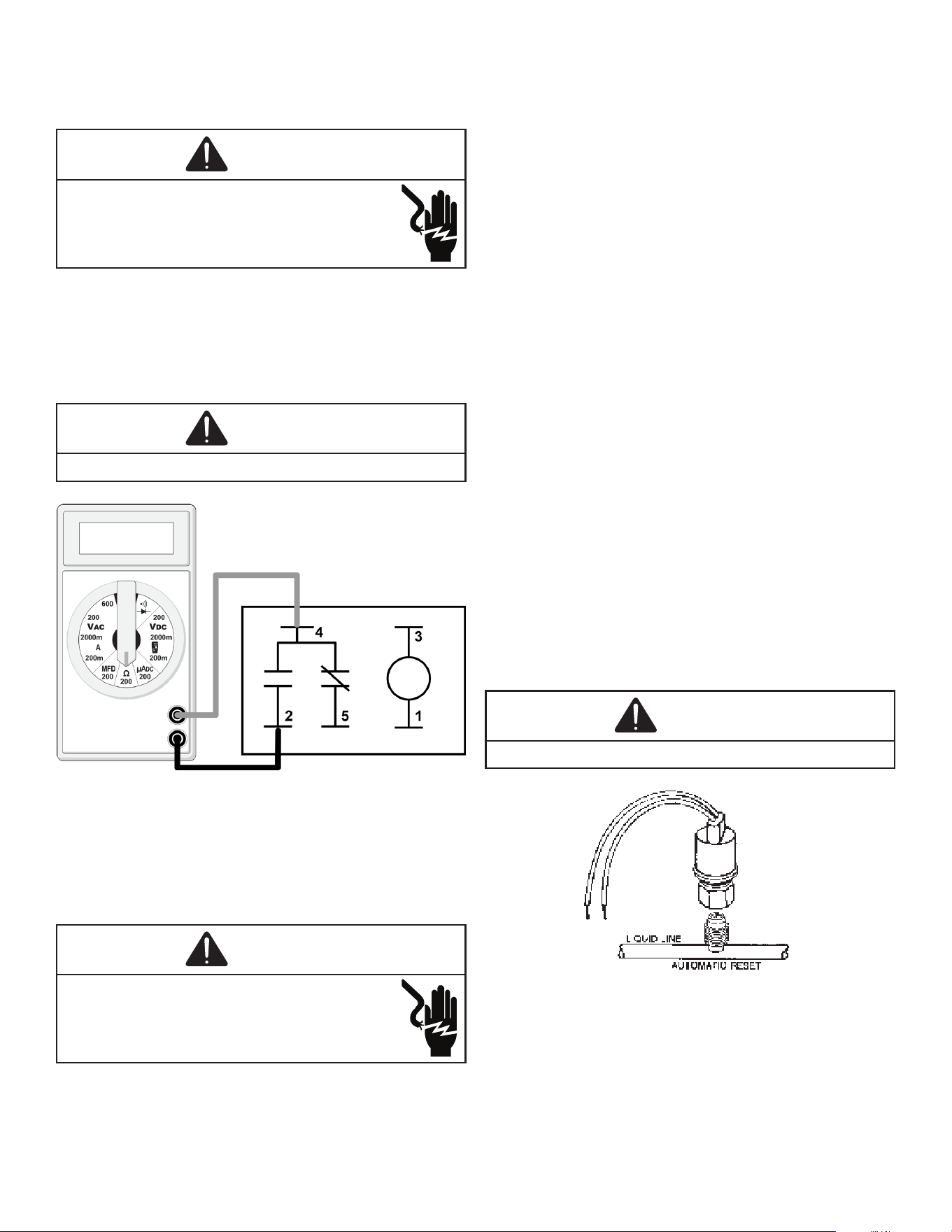
1. Disconnect wire leads from terminals 2 and 4 of Fan
Relay Cooling and 2 and 4, 5 and 6 of Fan Relay
Heating.
2. Using an ohmmeter, test between 2 and 4 - should read
open. Test between 5 and 6 - should read continuous.
3. With power ON, energize the relays.
WARNING
Line voltage now present.
Testing Fan Relay
4. Using an ohmmeter, test between 2 and 4 - should read
continuous. Test between 5 and 6 - should read open.
5. If not as above, replace the relay.
Checking High Pressure Control
WARNING
High Voltage!
Disconnect all power before servicing or
installing. Multiple power sources may be present.
Failure to do so may cause property damage,
personal injury or death.
The high pressure control capillary senses the pressure
in the compressor discharge line. If abnormally high
condensing pressures develop, the contacts of the control
open, breaking the control circuit before the compressor
motor overloads. This control is automatically reset.
Test 1. Testing High Pressure Control in Cooling Mode
1. Connect refrigerant gages to unit.
2. Disconnect power to outdoor unit.
3. Remove control panel cover.
4. Disconnect black wire from condenser fan motor
(single stage units) or remove plug from control board
on 2 stage units. NOTE: Tape or isolate black wire to
prevent possible short.
5. Apply power to unit and set thermostat to cool and set
for all for cool.
6. High pressure switch should open at 610 PSIG +/- 10
PSIG and close at 420 PSIG +/- 25 PSIG.
7. If high pressure switch does not operate in these
parameters replace switch.
Test 2. Testing High Pressure Control in Heating Mode
1. Connect refrigerant gages to unit.
2. Disconnect power to indoor unit.
3. Remove control panel cover.
4. Disconnect black wire from evaporator fan motor
(single stage units) or remove plug from control board
on 2 stage units. NOTE: Tape or isolate black wire to
prevent possible short.
5. Apply power to unit and set thermostat to heat and set
for call for heat.
6. High pressure switch should open at 610 PSIG +/- 10
PSIG and close at 420 PSIG +/- 25 PSIG.
7. If high pressure switch does not operate in these
parameters replace switch.
With power ON:
WARNING
Line voltage now present.
18
SERVICING
Checking Low Pressure Control
The low pressure control senses the pressure in the suction
line and will open its contacts on a drop in pressure. The
low pressure control will automatically reset itself with a rise
in pressure.
Test 1. Testing Low Pressure Control in Cooling Mode
1. Connect refrigerant gages to unit.
2. Disconnect power to indoor unit.
3. Remove control panel cover.
4. Disconnect black wire from evaporator fan motor
(single stage units) or remove plug from control board
on 2 stage units. NOTE: Tape or isolate black wire to
prevent possible short.
5. Apply power to unit and set thermostat to cool and set
for a call for cool.
6. Low pressure switch should open at 21 PSIG, and auto
reset (close) at approximately 50 PSIG.
7. If low pressure switch does not operate in these
parameters replace switch.
Test 2. Testing Low Pressure Control in Heating Mode
1. Connect refrigerant gages to unit.
2. Disconnect power to outdoor unit.
3. Remove control panel cover.
4. Disconnect black wire from condenser fan motor
(single stage units) or remove plug from control board
on 2 stage units. NOTE: Tape or isolate black wire to
prevent possible short.
5. Apply power to unit and set thermostat to cool and set
for all for cool.
6. Low pressure switch should open at 21 PSIG and auto
reset (close) at approximately 50 PSIG.
7. If low pressure switch does not operate in these
parameters replace switch.
Copeland Coresense™ Diagnostics - 3-Wire
module Applies to DC4SEA, DC5SEA,
DH4SEA and DH5SEA
WARNING
High Voltage!
Disconnect all power before servicing or
installing. Multiple power sources may be present.
Failure to do so may cause property damage,
personal injury or death.
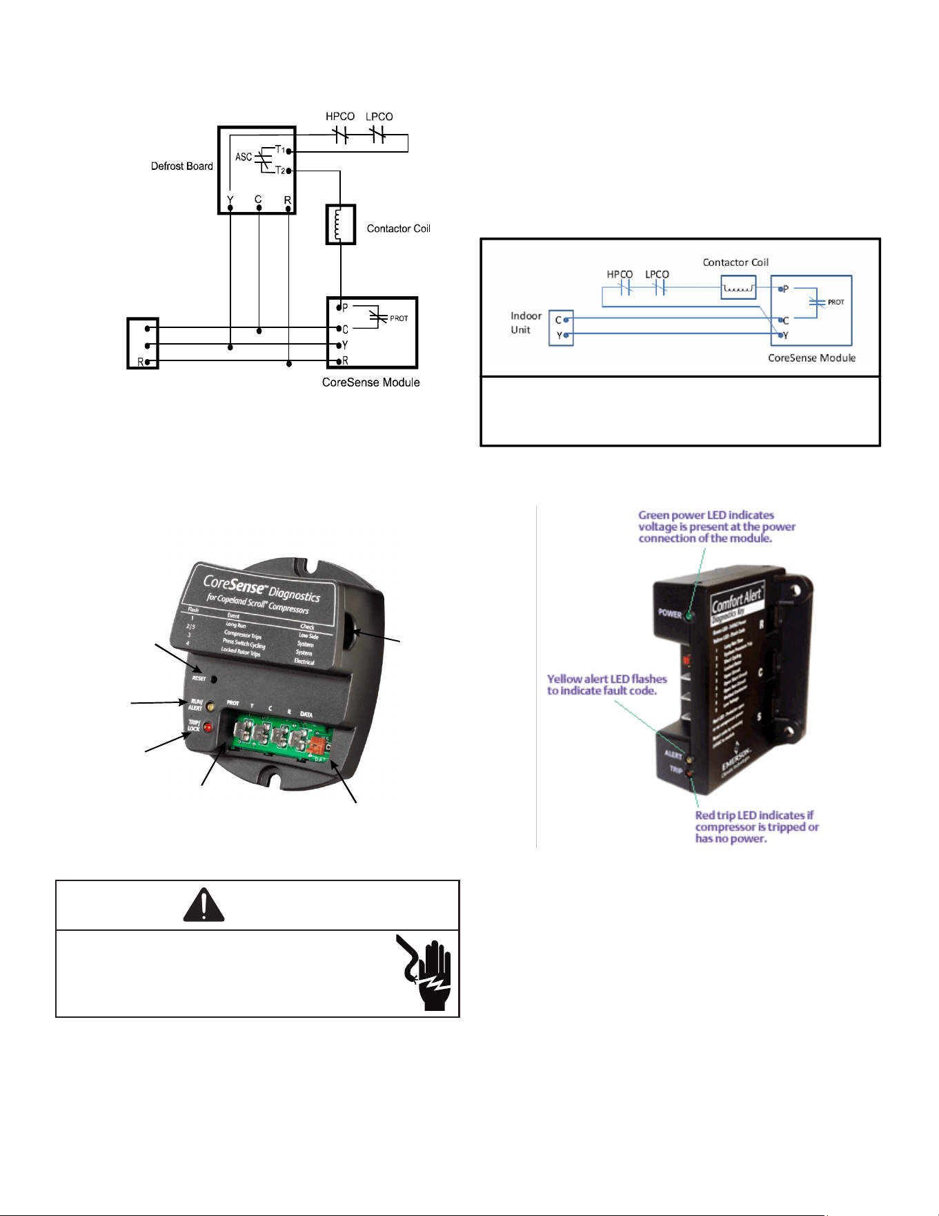
The CoreSense™ module is self-contained with no
required external sensors and works with any residential
condensing unit that has a Copeland Scroll™ compressor
inside.
Once attached, CoreSense™ provides around-the-clock
monitoring for common electrical problems, compressor
defects and broad system faults. If a glitch is detected, an
LED indicator ashes the proper alert codes to help you
quickly pinpoint the problem. See Diagnostic Table: 3-Wire
CoreSense™ Module on following pages.
19
SERVICING
C
Y
Indoor
Unit
Schematic Abbreviation Descriptions
HTCO High Temperature Cut Out Switch
HPCO High Pressure Cut Out Switch
LPCO Low Pressure Cut Out Switch
CC Compressor Contactor
ECB Electronic Control Board
(Defrost or Time Delay)
Wiring Schematic - 3-Wire Coresense™ Alert Module
Reset
Switch
Run/Alert
LED
Trip/Lock-Out
Red LED
Protection
Output
Data Port
One
Current
Sensor
Diagnostics - 2-Wire Module
Applies to
WARNING
High Voltage!
Disconnect all power before servicing or
installing. Multiple power sources may be present.
Failure to do so may cause property damage,
personal injury or death.
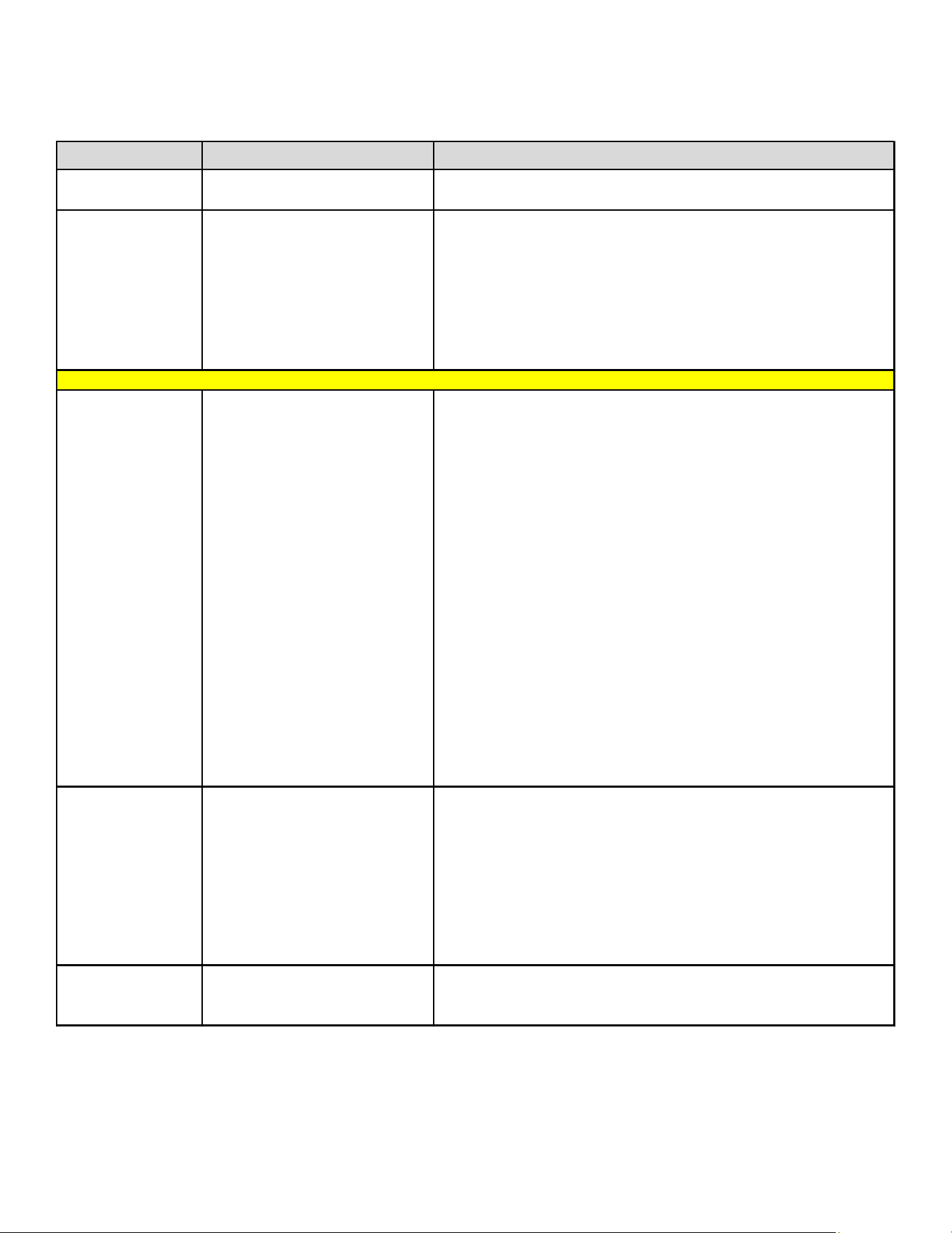
The CoreSense™ module is self-contained with no
required external sensors and works with any residential
condensing unit that has a Copeland Scroll™ compressor
inside.
Once attached, CoreSense™ provides around-the-clock
monitoring for common electrical problems, compressor
defects and broad system faults. If a glitch is detected, an
LED indicator ashes the proper alert codes to help you
quickly pinpoint the problem. See Diagnostic Table: 2-Wire
Comfort Alert™ Module on following pages.)
Schematic Abbreviation Descriptions
HTCO High Temperature Cut Out Switch
HPCO High Pressure Cut Out Switch
LPCO Low Pressure Cut Out Switch
CC Compressor Contactor
ECB Electronic Control Board
(Defrost or Time Delay)
Wiring Schematic - 2-Wire Coresense™ Module
20
SERVICING
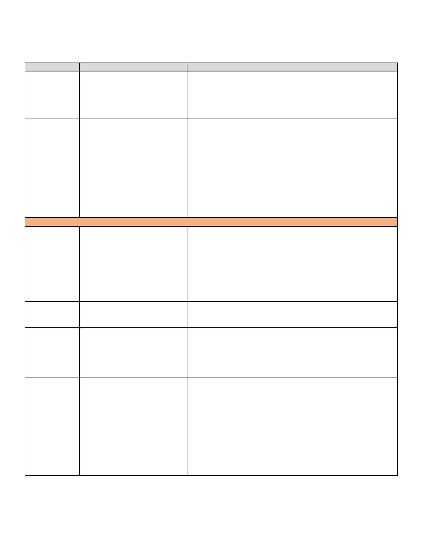
Diagnostics Table: Coresense™ Module
Flash code number corresponds to the number of LED ashes, followed by a pause and then repeated. TRIP and ALERT
LEDs ashing at the same time mean control circuit voltage is too low for operation.
Status Description Troubleshooting Information
Solid Yellow "RUN"
Module has power and operating
normally
Supply voltage is present at module terminals
Solid Red "TRIP"
Thermostat demand signal Y is
present, but the compressor is
not running
1. Compressor protector is open
• Check for high head pressure
• Check compressor supply voltage
2. Outdoor unit power disconnect is open
3. Compressor circuit breaker or fuse(s) is open
4. Broken wire or connector is not making contact
5. High pressure switch open if present in system
6. Compressor contactor has failed open
Yellow "ALERT"
Flash Code 1
Long Run Time; Compressor is
running extremely long run
cycles indicative of low capacity
due to a system low-side fault
1. Low refrigerant charge
2. Evaporator blower is not running
• Check blower relay coil and contacts
• Check blower motor capacitor
• Check blower motor for failure or blockage
• Check evaporator blower wiring and connectors
• Check indoor blower control board
• Check thermostat wiring for open circuit
3. Evaporator coil is frozen
• Check for low suction pressure
• Check for excessively low thermostat setting
• Check evaporator airflow (coil blockages or return air filter)
• Check ductwork or registers for blockage
4. Faulty metering device
• Check TXV bulb installation (size, location and contact)
• Check if TXV/fixed orifice is stuck closed or defective
5. Liquid line restriction (filter drier blocked if present in system)
6. Thermostat is malfunctioning
• Check thermostat sub-base or wiring for short circuit
• Check thermostat installation (location, level)
Yellow "ALERT"
Flash Code 2
Compressor (Pressure) Trip;
Discharge pressure out of limits
or compressor overloaded
1. Condenser fan is not running
• Check fan capacitor
• Check fan wiring and connectors
• Check fan motor for failure or blockage
2. High head pressure
• Check high pressure switch if present in system
• Check if system is overcharged with refrigerant
• Check for non-condensable in system
3. Condenser coil poor air circulation (dirty, blocked, damaged)
Yellow "ALERT"
Flash Code 3
Short Cycling; Compressor is
running only briefly
1. Thermostat demand signal is intermittent
2. Time delay relay or control board defective
3. Low or high pressure switch is cycling
"ALERT" Flash Codes
21
SERVICING
Diagnostics Table: Coresense™ Module
Flash code number corresponds to the number of LED ashes, followed by a pause and then repeated. TRIP and ALERT
LEDs ashing at the same time mean control circuit voltage is too low for operation.
Status Description
Troubleshooting Information
Yellow "ALERT"
Flash Code 4
Locked Rotor
1. Run capacitor has failed
2. Low line voltage (contact utility if voltage at disconnect is low)
• Check wiring connections
3. Excessive liquid refrigerant in compressor
4. Compressor bearings are seized
• Measure compressor oil level
Yellow "ALERT"
Flash Code 5
Compressor (Moderate Run) Trip
1. Evaporator blower is not running
• Check blower relay coil and contacts
• Check blower motor capacitor
• Check blower motor for failure or blockage
• Check evaporator blower wiring and connectors
• Check indoor blower control board
• Check thermostat wiring for open circuit
2. Faulty metering device
• Check TXV bulb installation (size, location and contact)
• Check if TXV/fixed orifice is stuck closed or defective
3. Condenser coil poor air circulation (dirty, blocked, damaged)
4. Low refrigerant charge
Red "LOCK"
Flash Code 2
Yellow Off
Compressor (Pressure) Trip;
Compressor is locked out after 4
consecutive or 10 total compressor
(pressure) trip events
1. Condenser fan is not running
• Check fan capacitor
• Check fan wiring and connectors
• Check fan motor for failure or blockage
2. High head pressure
• Check high pressure switch if present in system
• Check if system is overcharged with refrigerant
• Check for non-condensable in system
3. Condenser coil poor air circulation (dirty, blocked, damaged)
Red "LOCK"
Flash Code 3
Yellow Off
Short Cycling; Compressor is locked
out after 10 consecutive short cycling
events
1. Thermostat demand signal is intermittent
2. Time delay relay or control board defective
3. If high pressure switch present go to Flash Code 2 information
Red "LOCK"
Flash Code 4
Yellow Off
Locked Rotor; Compressor is locked
out after 10 consecutive locked rotor
events
1. Run capacitor has failed
2. Low line voltage (contact utility if voltage at disconnect is low)
• Check wiring connections
3. Excessive liquid refrigerant in compressor
4. Compressor bearings are seized
• Measure compressor oil level
Red "LOCK"
Flash Code 5
Yellow Off
Compressor (Moderate Run) Trip;
Compressor is locked out after 4
consecutive or 10 total compressor
(moderate run) trip events
1. Evaporator blower is not running
• Check blower relay coil and contacts
• Check blower motor capacitor
• Check blower motor for failure or blockage
• Check evaporator blower wiring and connectors
• Check indoor blower control board
• Check thermostat wiring for open circuit
2. Faulty metering device
• Check TXV bulb installation (size, location and contact)
• Check if TXV/fixed orifice is stuck closed or defective
3. Condenser coil poor air circulation (dirty, blocked, damaged)
4. Low refrigerant charge
"LOCK" Flash Codes
22
SERVICING
Table 1 - Quick Reference Table
Alert Code Alert Condition Lock Level Lock Indication
Normal Run
Solid Yellow
Normal operation, no trip N/A N/A
Code1
Yellow Flash 1
Long run time. Compressor is on running for more than 18
hours. (Code1 is disabled in Heat Pump mode.)
N/A N/A
Code2
Yellow Flash 2
Compressor (pressure) trip. Compressor runs for 12 sec
to 15 min followed by a compressor trip condition lasting
longer than 7 min.
4x consecutive
Red: Flash 2
Yellow: Off
Code3
Yellow Flash 3
Pressure switch cycling. Compressor runs for 12 sec to
15 min followed by a compressor trip lasting between 35
sec to 7 min.
4x consecutive
or 10x total
Red: Flash 3
Yellow: Off
Code4
Yellow Flash 4
Locked rotor. Compressor trips within a compressor run
time of 12 sec and does not start within 35 sec.
10x
consecutive
Red: Flash 4
Yellow: Off
Code5
Yellow Flash 5
Compressor (moderate run) trip. Compressor runs for 15
min to 18 hrs followed by a compressor trip lasting longer
than 7 min.
4x consecutive
or 10x total
Red: Flash 5
Yellow: Off
Code9
Red Flash 9
The current to the PROT terminal is greater than 2A
Current > 2A
for 40ms
Red: Flash 9
Yellow: Off
Trip
Solid Red
Demand is present, but compressor is not running N/A N/A
23
SERVICING
Checking Capacitor
Capacitor, Run
A run capacitor is wired across the auxiliary and main
windings of a single phase permanent split capacitor
motor. The capacitors primary function is to reduce the line
current while greatly improving the torque characteristics
of a motor. This is accomplished by using the 90° phase
relationship between the capacitor current and voltage
in conjunction with the motor windings, so that the motor
will give two phase operation when connected to a single
phase circuit. The capacitor also reduces the line current to
the motor by improving the power factor.
The line side of this capacitor is marked with “COM” and is
wired to the line side of the circuit.
Resistance Check Using A Digital Multi-Meter
WARNING
High Voltage!
Disconnect all power before servicing or
installing. Multiple power sources may be present.
Failure to do so may cause property damage,
personal injury or death.
Check for Digital Test
1. Set the meter on Ohm range (Set it at lease 1000
Ohm=1k).
WARNING
Discharge capacitor through a 200 to 300 OHM resistor
before handling.
2. Connect the Meter leads to the Capacitor terminals.
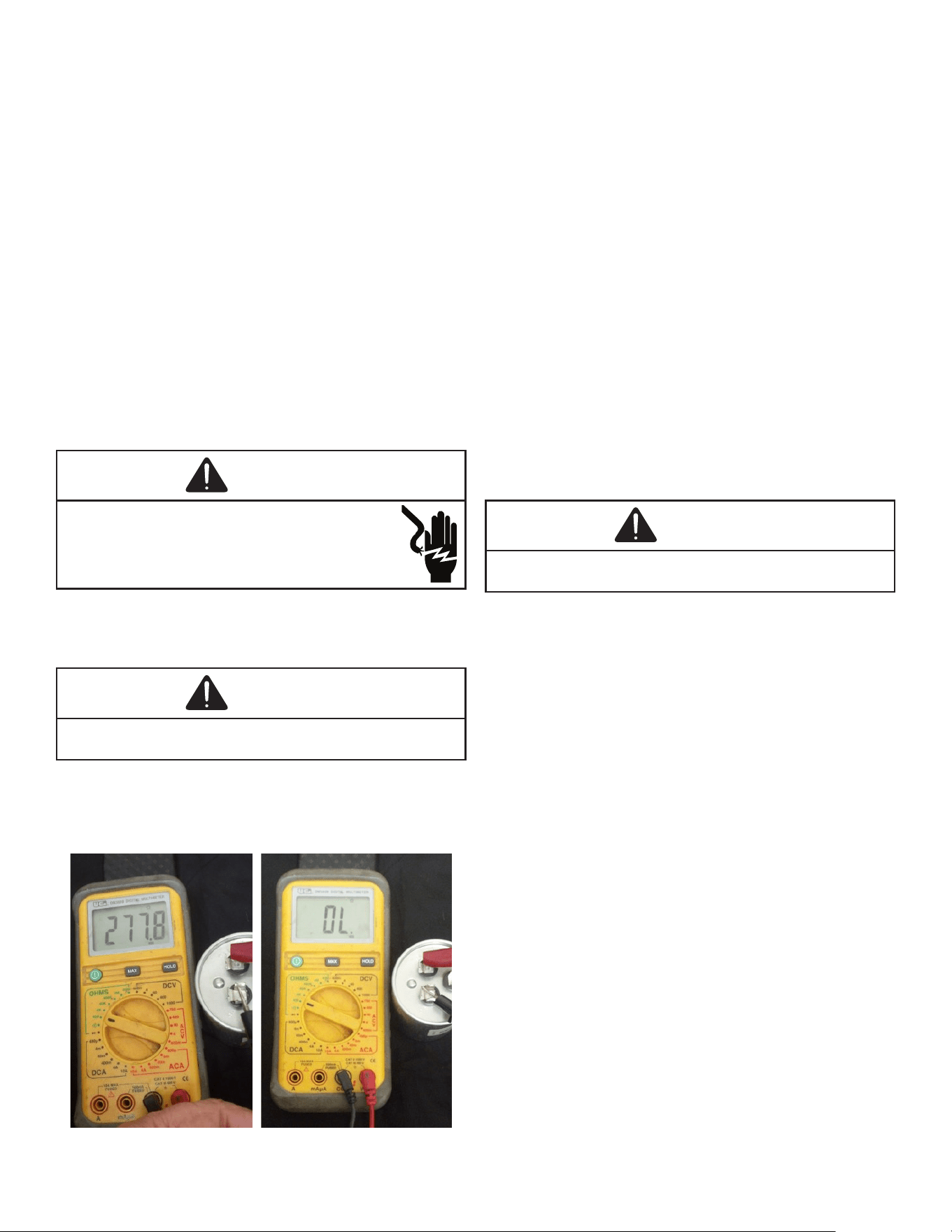
3. Digital meter will show a reading momentarily (Figure
1). Note the reading.
Figure 1 Figure 2
4. Reading will immediately return to the OL = (Open
Line) (Figure 2). Every attempt of Step 2 will show the
same result as was in step 4 and Step 5. This indicates
that the capacitor is good.
5. If there is no Change, then capacitor is dead and must
be replaced.
Check for Analog Meter
1. Good Condition - indicator swings to zero and slowly
returns to innity (Start capacitor with bleed resistor will
not return to innity. It will still read the resistance of the
resistor).
2. Shorted - indicator swings to zero and stops there -
replace.
3. Open - no reading - replace (Start capacitor would read
resistor resistance).
Capacitance Check Using A Digital Multi-
Meter
(In Capacitance Mode)
WARNING
Discharge capacitor through a 200 to 300 OHM resistor
before handling.
NOTE: You can do this test with a multi-meter if you
have a Capacitance meter on your multi-meter.
1. Remove the capacitor from the circuit.
2. Now Select “Capacitance” on your multi-meter.
3. Now connect the capacitor terminals to the multi-meter
leads.
4. If the reading is near to the actual value of the capacitor
(i.e. the printed value on the capacitor). The capacitor
is good (Note that the reading may be less than the
actual printed value of the capacitor).
5. If you read a signicantly lower capacitance or none at
all, then capacitor is dead and must be replaced.
Capacitor, Start
Scroll Compressor Models
In most cases hard start components are not required on
Scroll compressor equipped units due to a non-replaceable
check valve located in the discharge line of the compressor.
However, in installations that encounter low lock rotor
voltage, a hard start kit can improve starting characteristics
and reduce light dimming within the home. Only hard
start kits approved by Amana® brand or Copeland should
be used. “Kick Start” and/or “Super Boost” kits are not
approved start assist devices.
The discharge check valve closes o high side pressure
to the compressor after shut down allowing equalization
through the scroll anks. Equalization requires only about
1/2 second.
24
SERVICING
To prevent the compressor from short cycling, a Time Delay
Relay (Cycle Protector) has been added to the low voltage
circuit.
Testing a Run Capacitor Under Load
1. Measure the amperage of the wire from Herm on the
capacitor to start terminal on compressor.
2. Multiply the amperage reading by the constant of 2,652
3. Measure voltage across the capacitor between “HERM”
and “C” terminals this is the measured voltage across
the start and run terminals on the compressor.
4. Divide total from step 2 by the voltage measurement.
This total is the capacitance. This give a more accurate
measurement of the capacitor’s performance.
5. Read the rated MFD on the capacitor and compare to
your actual readings. If outside of +/- tolerance stated
on the capacitor, replacement of the capacitor may be
recommended.
Formula: Start Winding Amps x 2,652 ÷ capacitor
voltage = microfarads.
Refrigerant Detection System (RDS)
Function: Refrigerant Detection System (RDS) is installed
in this equipment to detect any R32 leakage in the coil and
take action to mitigate any risk of ignition/ re.
Operation: When there is leak detected, the RDS shall
send signals for the unit to perform these actions:
1. Turn o the Thermostat
2. Turn on the blower for air circulation
3. Switch o electric heater
Servicing:
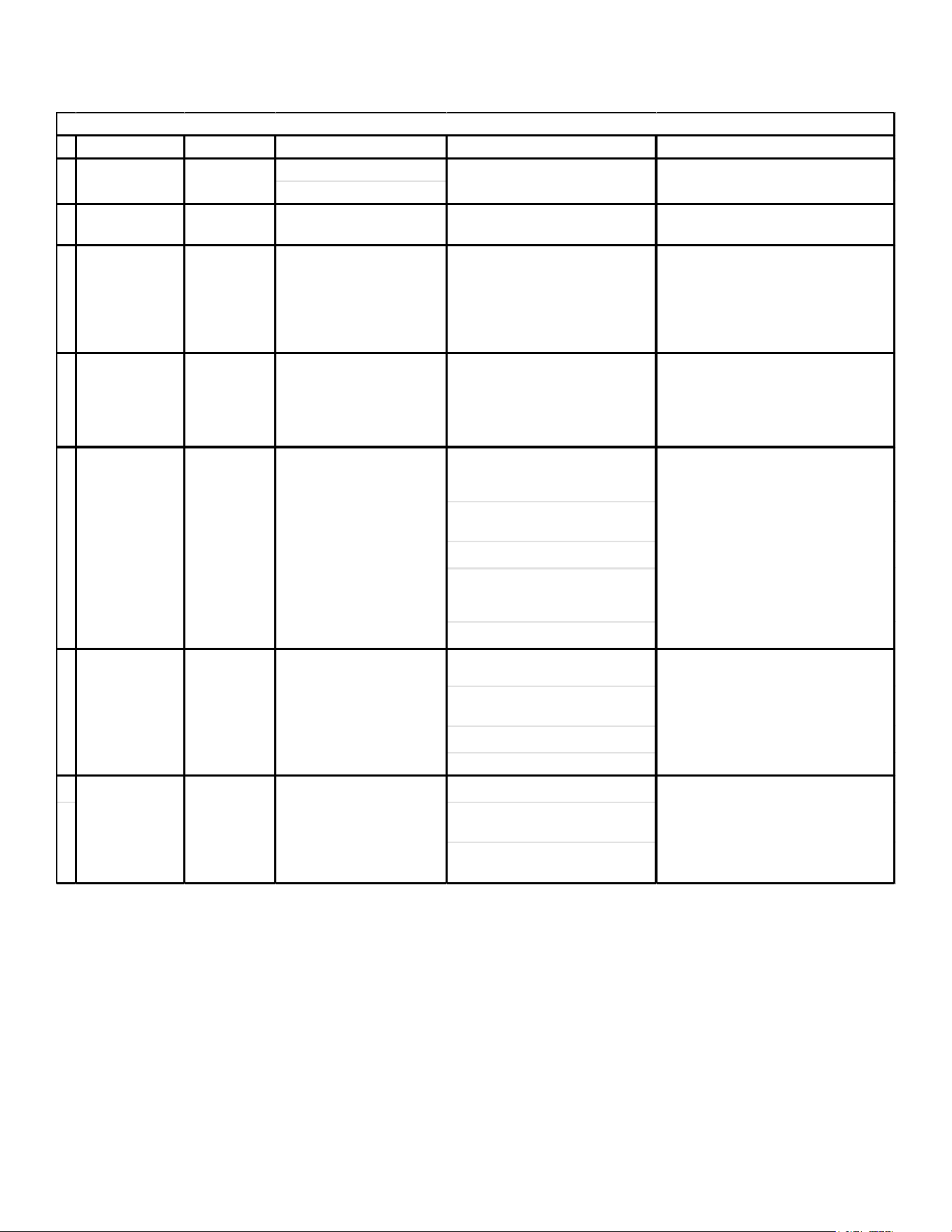
Before servicing identify the Mode of operation of the
system by reading the LED ashing pattern on the PCB
which can be seen through the round glass view on top
access panel and matching the LED ashing pattern
with mode of operation in A2L PCB fault code label
which is attached on the front side of the blower access
panel. See the following “A2L PCB FAULT CODE”
table. After identifying the mode of operation refer to the
“RECOMMENDED ACTION FOR PCB LED FLASHING
CODES” table and take recommended actions as specied
in the table.
LEAK DETECTION SYSTEM INSTALLED. UNIT MUST BE
POWERED EXCEPT FOR SERVICE.
RED LED'S STATUS (REFER I/O FOR RECOMMENDED
ACTION)
MODE LED FLASHING PATTERN
NORMAL OPERATION
SLOW LED FLASHING PATTERN
(2 SECONDS ON 2 SECONDS OFF)
R-32 LEAK ALARM FAST LED FLASHING PATTERN
DELAY MODE LED WILL BE ON CONTINUOUSLY
SYSTEM
VERFICATION MODE
SAME AS R32 LEAK ALARM MODE
CONTROL BOARD
INTERNAL FAULT
LED WILL FLASH 2 TIMES AND THEN
BE OFF FOR 5 SECONDS
R32 SENSOR
COMMUNICATION
FAULT
LED WILL FLASH 3 TIMES AND THEN
BE OFF FOR 5 SECONDS
R32 SENSOR FAULT
LED WILL FLASH 4 TIMES AND THEN
BE OFF FOR 5 SECONDS
*
IF R-32 LEAK ALARM IS OBSERVED,
DO NOT OPEN THE UNIT OR
TURN IT OFF.
0140A01138-B
*
A2L PCB FAULT CODE
25
SERVICING
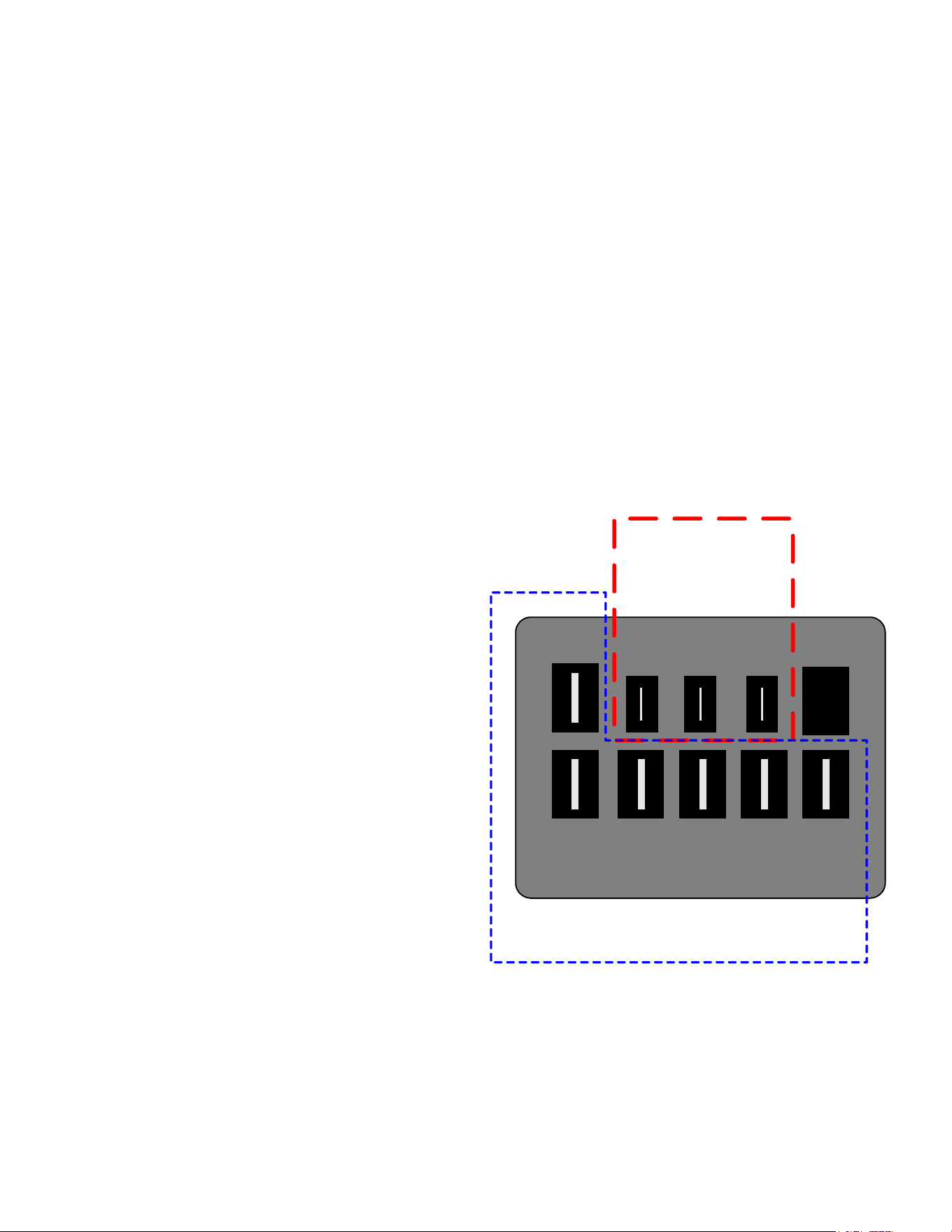
MODE Definition LED Flashing Pattern Recommended actions Notes:
Slow LED flashing pattern
(2 seconds on and 2 seconds off)
2 R32 Leak Alarm
R32 leak is
currently being
detected
Fast LED Flashing Pattern
The controls and sensor are working
properly. Identify where the leak is coming
from and address the leak.
3 Delay Mode
After R32 leak or
Alarm has been
cleared, the unit
will remain in alarm
mode for 5
minutes before
returning to
normal operation
LED will be on continuously
Check HVAC performance (Cooling and
Heating Modes). Check system pressures
and lines for any leaks. Re-Check HVAC
performance after addressing any issues.
After any alarm or fault, it is required to remain in
R32 mitigation mode for 5 minutes.
4
System Verification
Mode
Manual test run by
contractor to
simulate R32 Leak
Alarm (test will last
for 5 minutes max)
Fast LED Flashing Pattern No actions needed
To Enter system verification test mode, press the
button on the control 2 times within 5 seconds. The
control will enter a simulated R32 Leak Alarm state
and remain in that mode for 5 minutes. After 5
minutes, the control will return to Normal Operation
automatically. If the contractor wants to end the
test early, they need to press the button one time.
1) Unplug and plug the R32 sensor back in.
Cycle power to the system.
2) If control is in Normal Operation or Delay
mode, there is no more issue. If not, continue
with diagnostics.
3) Unplug R32 sensor and leave unplugged.
Cycle power to the system
4) If control still displays "Control Board
Internal Fault" (2 flash pattern) replace the
control. If control now displays "R32 Sensor
Communication Fault" (3 flash pattern)
replace the sensor
1) Unplug and plug the R32 sensor back in.
Cycle power to the system.
2) If control is in Normal Operation or Delay
mode, there is no more issue. If not, continue
with diagnostics.
3) If control still displays "R32 Sensor
Communication Fault" (3 flash pattern),
Relace both the sensor and the PCB
1) Unplug and plug the R32 sensor back in.
Cycle power to the system.
2) If control is in Normal Operation or Delay
mode, there is no more issue. If not, continue
with diagnostics.
3) If control still displays "R32 Sensor Fault"
(4 flash pattern), Relace both the sensor.
7
R32 Sensor Fault
R32 Sensor has
reported an
internal issue
LED will blink 4 times and then be off
for 5 seconds before repeating the
pattern
This means communications to the sensor are
perfectly fine. The sensor itself is reporting an
internal fault.
Control Board Internal
Fault
Control board has
detected an issue
with the R32
detection system
LED will flash 2 times and then be off
for 5 seconds before repeating the
pattern
These steps will determine if the error is on the
board or external to the board.
6
5
R32 Sensor
Communication Fault
Control board
does not have
communications
with R32 sensor
LED will flash 3 times and then be off
for 5 seconds before repeating the
pattern
If the control cannot talk to the sensor there could
be a problem with the sensor, a problem with the
sensor harness or a problem internal to the control.
The field will not be able to measure anything to
reliably fix this error assuming the connector is
properly secured to the control. Replacing both is
the only option.
RED LED'S STATUS
1
Normal Operation
No faults to report
No action
RECOMMENDED ACTION FOR PCB LED FLASHING CODES
26
SERVICING
Instruction to replace A2L PCB:
Take o the blower access panel, disconnect the PCB
harness and R32 sensor wire connected to the PCB,
detach the defective PCB from the 4 plastic standos,
install new PCB on 4 plastic standos which is installed
on metal bracket, re-connect the PCB harness and R32
sensor wire to the new PCB per wiring instruction as
attached to the equipment, reassemble the blower access
panel to the unit.
Instruction to replace R32 sensor:
Take o the blower access panel and coil access panel,
take o the drain port gasket on the drain pan in front of the
sensor bracket, disconnect the R32 sensor wire from the
A2L PCB, take o sensor bracket assembly from the drain
pan, remove plastic push pins and non-function R32 sensor
o the sensor bracket, install new R32 sensor and plastic
push pins to sensor bracket, re-install A2L sensor bracket
assembly to the drain port correctly as shown in the gures
in the Installation Manual. The “FRONT” print on sensor
bracket should be facing away from the equipment, place
gaskets back to the drain ports correctly. The “FRONT”
print on the gaskets should be in the front facing away from
the equipment, reassemble the blower access panel and
coil access panel to the unit.
IMPORTANT NOTE: The R32 Sensor shall only be
replaced with sensors specied by the appliance
manufacturer.
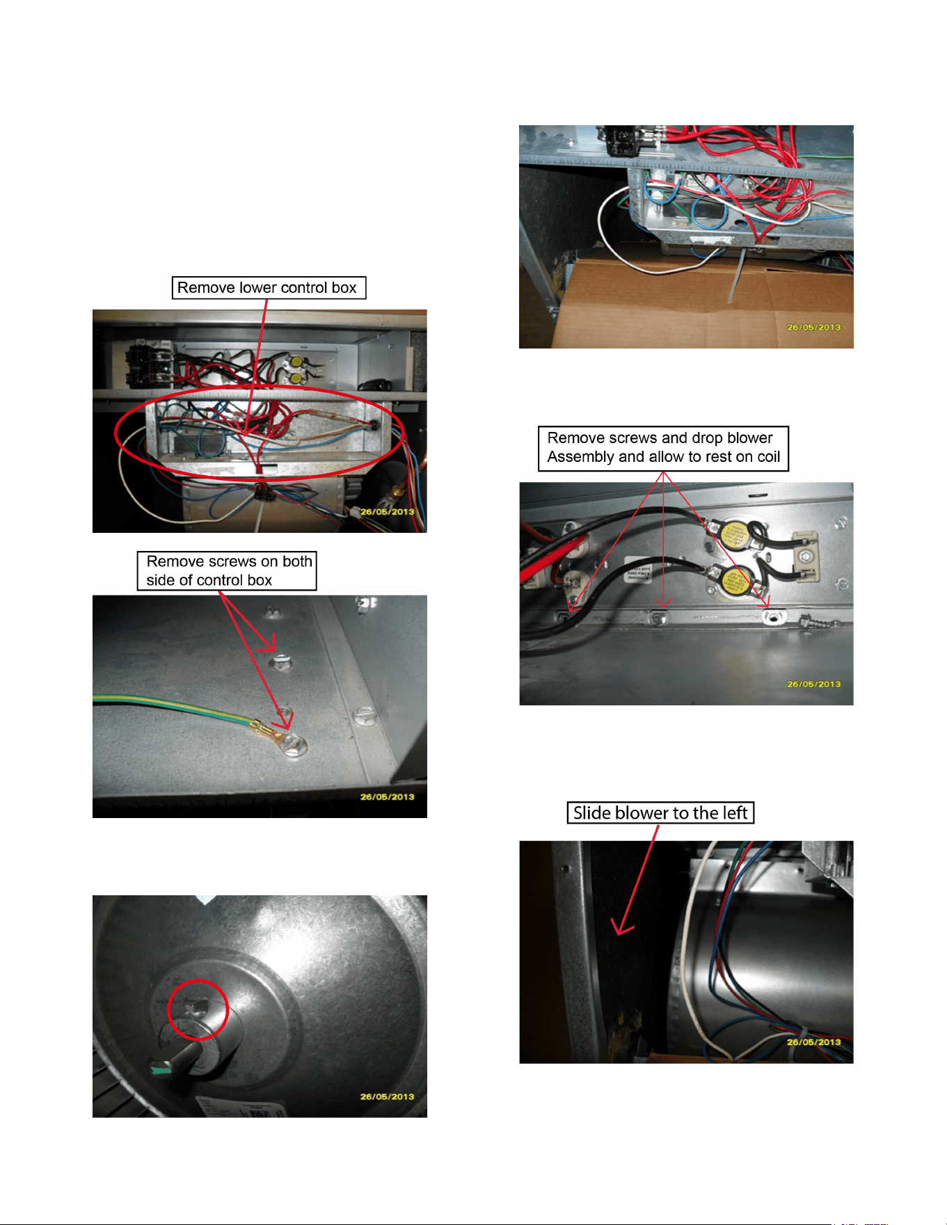
Checking High Eciency Motors
The motor is a one piece, fully encapsulated, 3 phase
brushless DC (single phase AC input) motor with ball
bearing construction.
1. Using a voltmeter, check for 230 volts to the motor
connections L and N. If 230 volts is present, proceed to
step 2. If 230 volts is not present, check the line voltage
circuit to the motor.
2. Using a voltmeter, check for 24 volts from terminal C to
either terminal 1, 2, 3, 4, or 5, depending on which tap
is being used, at the motor. If voltage present, proceed
to step 3. If no voltage, check 24 volt circuit to motor.
3. If voltage was present in steps 1 and 2, the motor has
failed and will need to be replaced.
NOTE: When replacing motor, ensure the belly band is
between the vents on the motor and the wiring has the
proper drip loop to prevent condensate from entering
the motor.
C
L G
N
1 2 3
4
5
High Voltage
Connections
3/16"
Low Voltage Connections
1/4”
Motor Connections
27
SERVICING
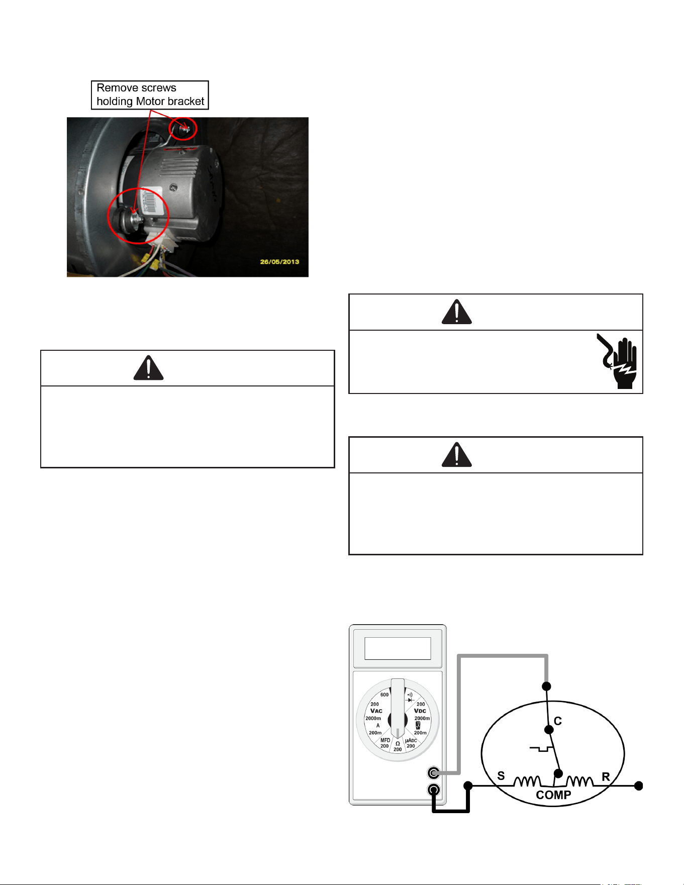
EEM Blower Replacement
For New AWST/AWSF R32 Air Handlers.
1. Disconnect power at main electrical panel.
2. Remove front access panel.
3. Remove the two screws on each side holding the lower
control box and move out of the way to give access to
the blower assembly
4. Loosen or remove set screw on blower wheel hub and
ensure the wheel slides freely on the shaft of the motor.
5. Install cardboard or rug over coil to protect ns from
damage.
6. Remove the three 3/8” screws holding the blower in
place.
7. Lower blower onto coil.
8. Slide blower assembly all the way to the left side of
cabinet.
9. Remove the bolts holding the motor bracket to the
blower and slide out of blower shell.
28
SERVICING
10. Replace the motor and reinstall blower and control box.
11. Reconnect power and test operation.
Checking Compressor
WARNING
Hermetic compressor electrical terminal venting can
be dangerous. When insulating material which supports
a hermetic compressor or electrical terminal suddenly
disintegrates due to physical abuse or as a result of an
electrical short between the terminal and the compressor
housing, the terminal may be expelled, venting the vapor and
liquid contents of the compressor housing and system.
If the compressor terminal PROTECTIVE COVER and
gasket (if required) are not properly in place and secured,
there is a remote possibility if a terminal vents, that the
vaporous and liquid discharge can be ignited, spouting
ames several feet, causing potentially severe or fatal injury
to anyone in its path.
This discharge can be ignited external to the compressor
if the terminal cover is not properly in place and if the
discharge impinges on a sucient heat source.
Ignition of the discharge can also occur at the venting
terminal or inside the compressor, if there is sucient
contaminant air present in the system and an electrical arc
occurs as the terminal vents.
Ignition cannot occur at the venting terminal without the
presence of contaminant air, and cannot occur externally
from the venting terminal without the presence of an
external ignition source.
Therefore, proper evacuation of a hermetic system is
essential at the time of manufacture and during servicing.
To reduce the possibility of external ignition, all open
ame, electrical power, and other heat sources should be
extinguished or turned o prior to servicing a system.
Resistance Test
Each compressor is equipped with an internal overload.
The line break internal overload senses both motor
amperage and winding temperature. High motor
temperature or amperage heats the disc causing it to open,
breaking the common circuit within the compressor on
single phase units.
Heat generated within the compressor shell, usually due to
recycling of the motor, high amperage or insucient gas to
cool the motor, is slow to dissipate. Allow at least three to
four hours for it to cool and reset, then retest.
Fuse, circuit breaker, ground fault protective device, etc.
has not tripped -
WARNING
High Voltage!
Disconnect all power before servicing or
installing. Multiple power sources may be present.
Failure to do so may cause property damage,
personal injury or death.
1. Remove the leads from the compressor terminals.
WARNING
Hermetic compressor electrical terminal venting can
be dangerous. When insulating material which supports
a hermetic compressor or electrical terminal suddenly
disintegrates due to physical abuse or as a result of an
electrical short between the terminal and the compressor
housing, the terminal may be expelled, venting the vapor and
liquid contents of the compressor housing and system.
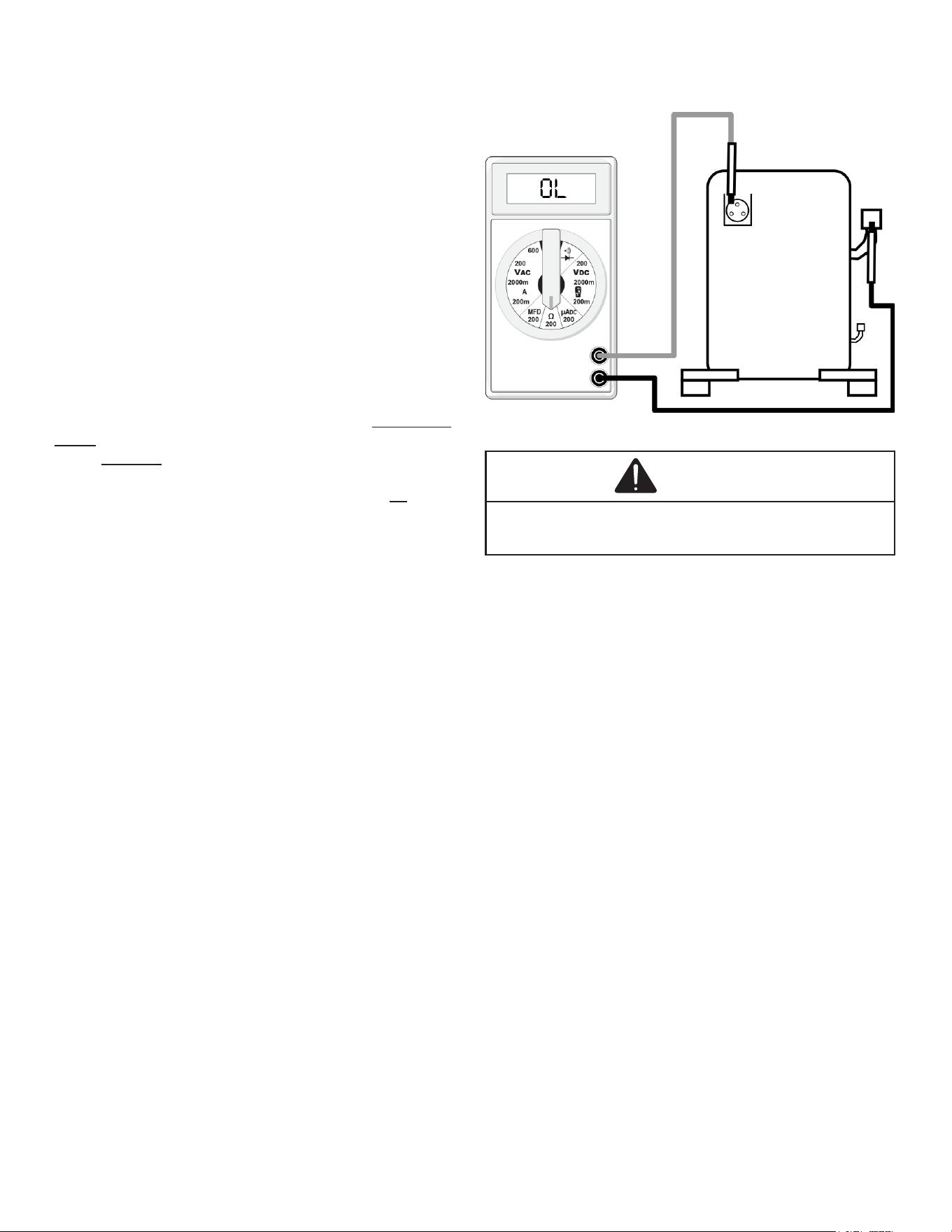
2. Using an ohmmeter, test continuity between terminals
S-R, C-R, and C-S, on single phase units or terminals
T2, T2 and T3, on 3 phase units.
Testing Compressor Windings
29
SERVICING
If either winding does not test continuous, replace the
compressor.
NOTE: If an open compressor is indicated, allow ample
time for the internal overload to reset before replacing
compressor.
Ground Test
If fuse, circuit breaker, ground fault protective device, etc.,
has tripped, this is a strong indication that an electrical
problem exists and must be found and corrected. The
circuit protective device rating must be checked, and its
maximum rating should coincide with that marked on the
equipment nameplate.
With the terminal protective cover in place, it is acceptable
to replace the fuse or reset the circuit breaker ONE TIME
ONLY to see if it was just a nuisance opening. If it opens
again, DO NOT continue to reset.
Disconnect all power to unit, making sure that all power
legs are open.
1. DO NOT remove protective terminal cover. Disconnect
the three leads going to the compressor terminals at
the nearest point to the compressor.
2. Identify the leads and using an ohmmeter on the R x
10,000 scale or the highest resistance scale on your
ohmmeter check the resistance between each of the
three leads separately to ground (such as an unpainted
tube on the compressor).
3. If a ground is indicated, then carefully remove the
compressor terminal protective cover and inspect for
loose leads or insulation breaks in the lead wires.
4. If no visual problems indicated, carefully remove the
leads at the compressor terminals.
5. Carefully retest for ground, directly between
compressor terminals and ground.
6. If ground is indicated, replace the compressor. The
resistance reading should be innity. If there is any
reading on meter, there is some continuity to ground
and compressor should be considered defective.
Compressor Ground Test
WARNING
Damage can occur to the glass embedded terminals if the
leads are not properly removed. This can result in terminal
and hot oil discharging.
Unloader Test Procedure
(2 Stage Compressors Only)
A nominal 24-volt direct current coil activates the
compressor internal unloader solenoid. The input control
circuit voltage must be 18 to 28 volt ac (remove). The
coil power requirement is 5 VA. The external electrical
connection is made with a molded plug assembly. This plug
contains a full wave rectier to supply direct current to the
unloader coil. The measured DC voltage at the connectors
in the plug should be 15 to 27 volt dc.
Unloader Test Procedure
If it is suspected that the unloader is not working, the
following methods may be used to verify operation.
1. Operate the system and measure compressor
amperage. Cycle the unloader ON and OFF at 10
second intervals. The compressor amperage should
increase when switching from part-load to full-load
and decrease when switching from full-load to part-
load. The percent change depends on the operating
conditions and voltage, but should be at least 25
percent.
2. If step one does not give the expected results, shut
unit o. Apply 18 to 28 volt ac to the unloader molded
plug leads and listen for a click as the solenoid pulls
in. Remove power and listen for another click as the
unloader returns to its original position.
30
SERVICING
3. If clicks can’t be heard, shut o power to the unit
and remove the control circuit molded plug from the
compressor and measure the unloader coil resistance
(connections on the compressor). The solenoid coil
should have continuity and not be grounded or have
innite resistance. If the coil resistance is innite, zero,
or grounded, the compressor must be replaced.
4. Next check the molded plug.
a. Voltage check: Apply control voltage to the plug
wires (18 to 28 volt ac). The measured dc voltage at
the female connectors in the plug should be around
15 to 27 vdc.
b. Resistance check: Measure the resistance from
the end of one molded plug lead to either of the
two female connectors in the plug. One of the
connectors should read close to zero ohms while
the other should read innity. Repeat with other wire.
The same female connector as before should read
zero while the other connector again reads innity.
Reverse polarity on the ohmmeter leads and repeat.
The female connector that read innity previously
should now read close to zero ohms.
Replace plug if either of these test methods doesn’t show
the desired results.
Operation Test
If the voltage, capacitor, overload and motor winding test
fail to show the cause for failure:
WARNING
High Voltage!
Disconnect all power before servicing or
installing. Multiple power sources may be present.
Failure to do so may cause property damage,
personal injury or death.
1. Remove unit wiring from disconnect switch and wire a
test cord to the disconnect switch.
NOTE: The wire size of the test cord must equal the
line wire size and the fuse must be of the proper size
and type.
2. With the protective terminal cover in place, use the
three leads to the compressor terminals that were
disconnected at the nearest point to the compressor
and connect the common, start and run clips to the
respective leads.
3. Connect good capacitors of the right MFD and voltage
rating into the circuit as shown.
4. With power ON, close the switch.
WARNING
Line voltage now present.
• If the compressor starts and continues to run, the
cause for failure is somewhere else in the system.
• If the compressor fails to start - replace.
COPELAND COMPRESSOR
03 A 12345 L
YEAR
MONTH
SERIAL
NUMBER
PLANT
Testing Crankcase Heater
(Optional Item)
The crankcase heater must be energized a minimum of
four (4) hours before the condensing unit is operated.
Crankcase heaters are used to prevent migration or
accumulation of refrigerant in the compressor crankcase
during the o cycles and prevents liquid slugging or oil
pumping on start up.
A crankcase heater will not prevent compressor damage
due to a oodback or over charge condition.
WARNING
Disconnect ALL power before servicing.
1. Disconnect the heater lead in wires.
2. Using an ohmmeter, check heater continuity - should
test continuous. If not, replace.
NOTE: The positive temperature coecient crankcase
heater is a 40 watt 265 voltage heater. The cool
resistance of the heater will be approximately 1800
ohms. The resistance will become greater as the
temperature of the compressor shell increases.
Checking Reversing Valve and Solenoid
Reversing valve used in heat pumps could potentially leak
internally. Discharge gases can leak into the suction inside
the valve. Compound gages will give the same symptoms
as bad compressor valves or broken scroll anks. The
temperature between true suction and the suction line after
the valve should not be greater than 4 degrees. Note: The
center tube is always the suction line and should be cold.

31
SERVICING
Troubleshooting the Reversing Valve for
Electrical Failure
1. Place unit into the cooling mode. Test for 24 volts at the
solenoid. If there is no voltage present at coil, check
the control voltage.
2. If voltage is present, loosen the nut on the top of the
coil. Remove the coil, there should be slight resistance.
3. If the slight resistance is felt, remove the coil. As you
remove the coil listen carefully, an audible click should
be detected. The clicking is due to the movement of the
pilot valve plunger. The absence of a clicking sound
indicates the plunger is stuck.
Troubleshooting Mechanical Failures on a
Reversing Valve by Pressure
1. Troubleshooting the reversing valve can be done by
pressure and touch.
2. Raise the head pressure. In the cooling mode block
the fan exhaust. Once head pressure has been raised,
cycle between cooling and heating and see if the piston
can be freed.
Troubleshooting Mechanical Failures on a
Reversing Valve by Temperature
1. When operating properly the valve contains refrigerant
gases at certain temperatures.
2. The discharge line should be the same temperature
after the valves discharge line.
3. The true suction should be the same as the suction line
after the valve. If there is a 4-degree dierence, valve
is leaking
When stuck in the mid-position, part of the discharge gas
from the compressor is directed back to the suction side,
resulting in excessively high suction pressure. An increase
in the suction line temperature through the reversing
valve can also be measured. Check operation of the valve
by starting the system and switching the operation from
COOLING to HEATING cycle.
If the valve fails to change its position, test the voltage
(24V) at the valve coil terminals, while the system is on the
COOLING cycle.
All heat pumps and communicating heat pumps wired
in legacy - If no voltage is registered at the coil terminals,
check the operation of the thermostat and the continuity
of the connecting wiring from the “O” terminal of the
thermostat to the unit.
If voltage is registered at the coil, tap the valve body lightly
while switching the system from HEATING to COOLING,
etc. If this fails to cause the valve to switch positions,
remove the coil connector cap and test the continuity of
the reversing valve solenoid coil. If the coil does not test
continuous - replace it.
If the coil test continuous and 24 volts is present at the coil
terminals, the valve is inoperative - replace it.
Testing Defrost Control
To check the defrost control for proper sequencing, proceed
as follows: With power ON; unit not running.
1. Jumper defrost thermostat by placing a jumper wire
across the terminals “DFT” and “R”/”R-DFT” at defrost
control board.
2. Remove jumper from timer pins and jump across
test pins on defrost control board. NOTE: Do not use
screwdriver or eld supplied jumper to test the control.
3. Set thermostat to call for heating. System should go
into defrost within 21 seconds
4. Immediately remove jumper from test pins.
5. Using VOM check for voltage across terminals “C & O”.
Meter should read 24 volts.
6. Using VOM check for voltage across fan terminals DF1
and DF2 on the board. You should read line voltage
(208-230 VAC) indicating the relay is open in the
defrost mode.
7. Using VOM check for voltage across “W”/”W2” & “C”
terminals on the board. You should read 24 volts.
8. If not as above, replace control board.
9. Set thermostat to o position and disconnect power.
Remove jumper from defrost thermostat and replace
timer jumper to the desired defrost time.
NOTE: Remove jumper across defrost thermostat
before returning system to service.
Testing Defrost Thermostat
1. Install a thermocouple type temperature test lead on
the tube adjacent to the defrost control. Insulate the
lead point of contact.
2. Check the temperature at which the control closes its
contacts by lowering the temperature of the control.
Part # 0130M00009P which is used on 2 and 2.5 ton
units should close at 34°F ± 5°F. Part # 0130M00001P
or B1370803 which is used on 3 thru 5 ton units should
close at 31°F ± 3°F.
3. Check the temperature at which the control closes its
contacts by lowering the temperature of the control.
Part # 0130M00085, which is used on units with 5 mm
coils, should close at 30°F ± 5°F.
32
SERVICING
4. Check the temperature at which the control opens its
contacts by raising the temperature of the control. Part
#0130M00009P which is used on 2 and 2.5 ton units
should open at 60°F ± 5°F. Part # 0130M00001P or
B1370803 which is used on 3 thru 5 ton units should
open at 75°F ± 6°F.
5. Check the temperature at which the control opens its
contacts by raising the temperature of the control. Part
# 0130M00085, which is used on units with 5 mm coils,
should open at 60°F ± 5°F.
6. If not as above, replace control.
WARNING
Disconnect ALL power before servicing.
Checking Heater Elements
Optional electric heaters may be added, in the quantities
shown in the spec sheet for each model unit, to provide
electric resistance heating. Under no condition shall more
heaters than the quantity shown be installed.
WARNING
High Voltage!
Disconnect all power before servicing or
installing. Multiple power sources may be present.
Failure to do so may cause property damage,
personal injury or death.
1. Disassemble and remove the heating element(s).
2. Visually inspect the heater assembly for any breaks in
the wire or broken insulators.
3. Using an ohmmeter, test the element for continuity -
no reading indicates the element is open. Replace as
necessary.
Electric Heater (Optional Item)
Optional electric heaters may be added, in the quantities
shown in the specications section, to provide electric
resistance heating. Under no condition shall more heaters
than the quantity shown be installed.
The low voltage circuit in the air handler is factory wired
and terminates at the location provided for the electric
heater(s). A minimum of eld wiring is required to complete
the installation.
Other components such as a Heating/Cooling Thermostat
and Outdoor Thermostats are available to complete the
installation.
The system CFM can be determined by measuring the
static pressure external to the unit. The installation manual
supplied with the blower coil, or the blower performance
table in the service manual, shows the CFM for the static
measured.
Alternately, the system CFM can be determined by
operating the electric heaters and indoor blower WITHOUT
having the compressor in operation. Measure the
temperature rise as close to the blower inlet and outlet as
possible.
If other than a 240V power supply is used, refer to the
BTUH CAPACITY CORRECTION FACTOR chart below.
BTUH CAPACITY CORRECTION FACTOR
SUPPLY VOLTAGE 250 230 220 208
MULTIPLICATION FACTOR 1.08 .92 .84 .75
EXAMPLE: Five (5) heaters provide 24.0 KW at the rated
240V. Our actual measured voltage is 220V, and our
measured temperature rise is 42°F. Find the actual CFM:
Answer: 24.0KW, 42°F Rise, 240 V = 1800 CFM from the
TEMPERATURE RISE chart on the right.
Heating output at 220 V = 24.0KW x 3.413 x .84 = 68.8
MBH.
Actual CFM = 1800 x .84 Corr. Factor = 1400 CFM.
NOTE: The temperature rise table is for sea level
installations. The temperature rise at a particular KW
and CFM will be greater at high altitudes, while the
external static pressure at a particular CFM will be less.
33
SERVICING
CFM
3.0
kW
4.8
kW
7.2
kW
9.6
kW
14.4
kW
19.2
kW
24.0
kW
28.8
kW
600 16 25 38 51 - - - -
700 14 22 33 43 - - - -
800 12 19 29 38 57 - - -
900 11 17 26 34 51 - - -
1000 10 15 23 30 46 - - -
1100 9 14 21 27 41 55 - -
1200 8 13 19 25 38 50 - -
1300 7 12 18 23 35 46 - -
1400 7 11 16 22 32 43 54 65
1500 6 10 15 20 30 40 50 60
1600 6 9 14 19 28 38 47 57
1700 6 9 14 18 27 36 44 53
1800 5 8 13 17 25 34 42 50
1900 5 8 12 16 24 32 40 48
2000 5 8 12 15 23 30 38 45
2100 5 7 11 14 22 29 36 43
2200 4 7 11 14 21 27 34 41
2300 4 7 10 13 20 26 33 39
TEMPERATURE RISE (°F) @ 240V
HTR
KW
3.0
KW
4.7
KW
6.0
KW
7.0
KW
9.5
KW
14.2
KW
19.5
KW
21.0
KW
BTUH 10200 16200 20400 23800 32400 48600 66500 71600
ELECTRIC HEATER CAPACITY BTUH
FORMULAS:
Heating Output = KW x 3413 x Corr. Factor
Actual CFM = CFM (from table) x Corr. Factor
BTUH = KW x 3413
BTUH = CFM x 1.08 x Temperature Rise (T)
CFM = KW x 3413
1.08 x T
T = BTUH
CFM x 1.08
Checking Heater Limit Control(s)
Each individual heater element is protected with a limit
control device connected in series with each element to
prevent overheating of components in case of low airow.
This limit control will open its circuit at approximately 150°F.
WARNING
High Voltage!
Disconnect all power before servicing or
installing. Multiple power sources may be present.
Failure to do so may cause property damage,
personal injury or death.
1. Remove the wiring from the control terminals.
2. Using an ohmmeter, test for continuity across the
normally closed contacts. No reading indicates the
control is open - replace if necessary.
If Found Open - Replace - Do Not Wire Around.
Checking Heater Fuse Link
(Optional Electric Heaters)
Each individual heater element is protected with a one time
fuse link which is connected in series with the element.
The fuse link will open at approximately 333°.
WARNING
Disconnect ALL power before servicing.
1. Remove heater element assembly so as to expose
fuse link.
2. Using an ohmmeter, test across the fuse link for
continuity - no reading indicates the link is open.
Replace as necessary.
NOTE: The link is designed to open at approximately
333°F. DO NOT WIRE AROUND - determine reason for
failure.
Refrigeration Repair Practice
DANGER
Always remove the refrigerant charge in a proper manner
before applying heat to the system.
When repairing the refrigeration system:
WARNING
High Voltage!
Disconnect all power before servicing or
installing. Multiple power sources may be present.
Failure to do so may cause property damage,
personal injury or death.
1. Never open a system that is under vacuum. Air and
moisture will be drawn in.
34
SERVICING
2. Plug or cap all openings.
3. Remove all burrs and clean the brazing surfaces of the
tubing with sand cloth or paper. Brazing materials do
not ow well on oxidized or oily surfaces.
4. Clean the inside of all new tubing to remove oils and
pipe chips.
5. When brazing, sweep the tubing with dry nitrogen to
prevent the formation of oxides on the inside surfaces.
6. Complete any repair by replacing the liquid line drier in
the system, evacuate and charge.
Brazing Materials
IMPORTANT NOTE: Torch heat required to braze
tubes of various sizes is proportional to the size of the
tube. Tubes of smaller size require less heat to bring
the tube to brazing temperature before adding brazing
alloy. Applying too much heat to any tube can melt the
tube. Service personnel must use the appropriate heat
level for the size of the tube being brazed.
NOTE: The use of a heat shield when brazing is
recommended to avoid burning the serial plate or the
nish on the unit. Heat trap or wet rags should be used
to protect heat sensitive components such as service
valves and TXV valves.
Copper to Copper Joints - Sil-Fos used without ux
(alloy of 15% silver, 80% copper, and 5% phosphorous).
Recommended heat 1400°F.
Copper to Steel Joints - Silver Solder used without
a ux (alloy of 30% silver, 38% copper, 32% zinc).
Recommended heat - 1200°F.
Standing Pressure Test (Recommended
before System Evacuation)
WARNING
To avoid the risk of fire or explosion, never use oxygen,
high pressure air or flammable gases for leak testing of a
refrigeration system.
WARNING
To avoid possible explosion, the line from the nitrogen
cylinder must include a pressure regulator and a pressure
relief valve. The pressure relief valve must be set to open at
no more than 450 psig.
Using dry nitrogen, pressurize the system to 450 PSIG.
Allow the pressure to stabilize and hold for 15 minutes
(minimum). If the pressure does not drop below 450 PSIG
the system is considered leak free. Proceed to system
evacuation using the Deep Vacuum Method. If after 15
minutes the pressure drops below 450 PSIG follow the
procedure outlined below to identify system leaks. Repeat
the Standing Pressure Test.
Leak Testing (Nitrogen or Nitrogen-Traced)
WARNING
To avoid the risk of fire or explosion, never use oxygen,
high pressure air or flammable gases for leak testing of a
refrigeration system.
WARNING
To avoid possible explosion, the line from the nitrogen
cylinder must include a pressure regulator and a pressure
relief valve. The pressure relief valve must be set to open at
no more than 450 psig.
Leak test the system using dry nitrogen and soapy
water to identify leaks. If you prefer to use an electronic
leak detector, charge the system to 10 PSIG with the
appropriate system refrigerant (see Serial Data Plate
for refrigerant identication). Do not use an alternative
refrigerant. Using dry nitrogen nish charging the system
to 450 PSIG. Apply the leak detector to all suspect areas.
When leaks are discovered, repair the leaks, and repeat
the pressure test. If leaks have been eliminated proceed to
system evacuation.
System Evacuation
Condensing unit liquid and suction valves are closed to
contain the charge within the unit. The unit is shipped with
the valve stems closed and caps installed. Do not open
valves until the system is evacuated.
WARNING
REFRIGERANT UNDER PRESSURE!
Failure to follow proper procedures may cause property
damage, personal injury or death.
NOTE: Scroll compressors should never be used
to evacuate or pump down a heat pump or air
conditioning system.
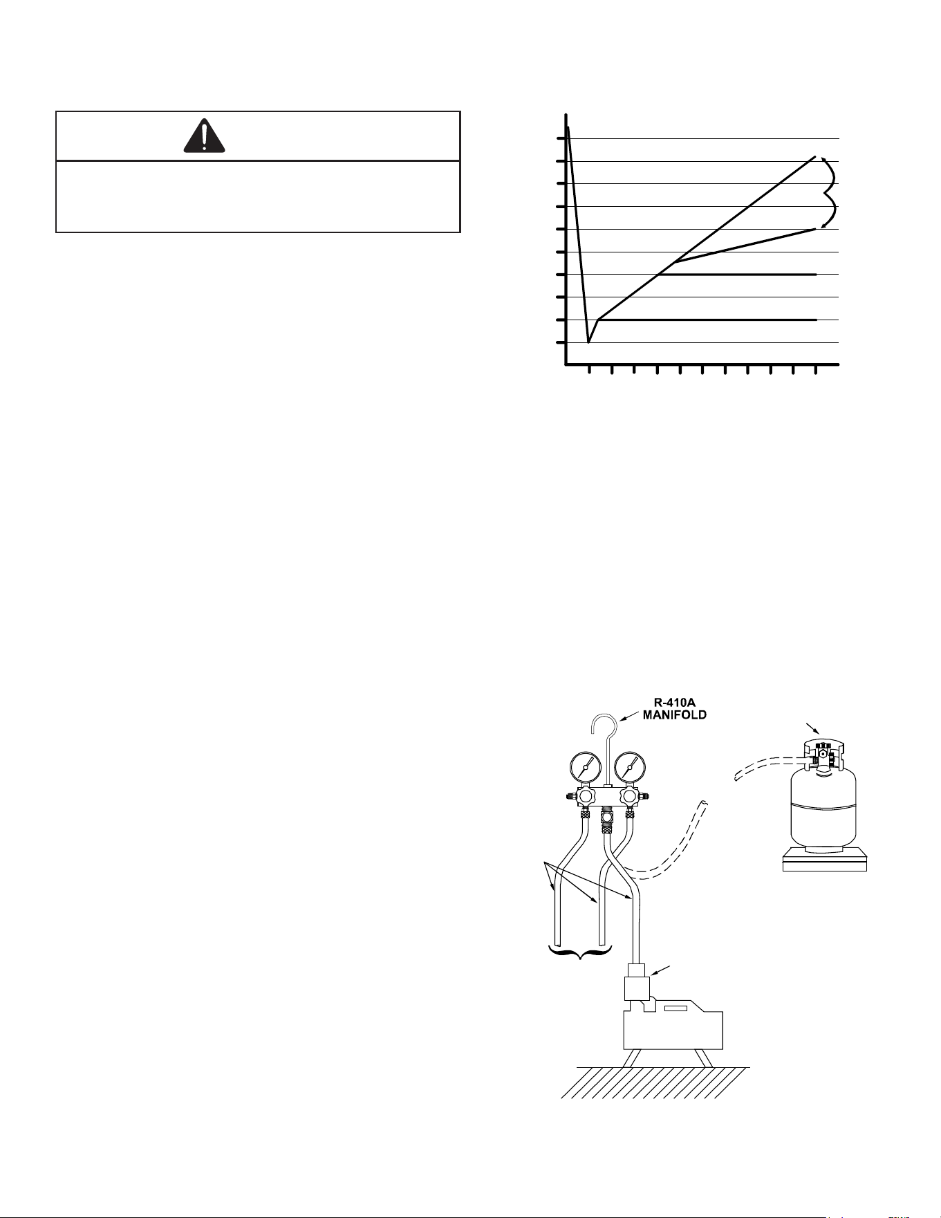
35
SERVICING
CAUTION
Prolonged operation at suction pressures less than 20 psig
for more than 5 seconds will result in overheating of the
scrolls and permanent damage to the scroll tips, drive
bearings and internal seal.
Deep Vacuum Method (Recommended)
The Deep Vacuum Method requires a vacuum pump
rated for 500 microns or less. This method is an eective
and ecient way of assuring the system is free of non-
condensable air and moisture. As an alternative, the Triple
Evacuation Method is detailed in the Service Manual for
this product model.
It is recommended to remove the Schrader Cores from the
service valves using a core-removal tool to expedite the
evacuation procedure.
1. Connect the vacuum pump, micron gauge, and vacuum
rated hoses to both service valves. Evacuation must
use both service valves to eliminate system mechanical
seals.
2. Evacuate the system to 500 microns or less using
suction and liquid service valves. Using both valves is
necessary as some compressors create a mechanical
seal separating the sides of the system.
3. Close pump valve and hold vacuum for 10 minutes.
Typically, pressure will rise during this period. If the
pressure rises to 1000 microns or less and remains
steady the system is considered leak-free; proceed to
startup.
4. If pressure rises above 1000 microns but holds steady
below 2000 microns, moisture and/or non-condensable
may be present or the system may have a small leak.
Return to step 2: If the same result is encountered
check for leaks as previously indicated and repair as
necessary then repeat evacuation.
5. If pressure rises above 2000 microns, a leak is present.
Check for leaks as previously indicated and repair as
necessary then repeat evacuation.
5000
4500
4000
3500
3000
2500
2000
1500
1000
500
0 1 2 3 4 5 6 7 8 9
10
LEAK(S)
PRESENT
MINUTES
V
ACUUM
IN
MICRONS
CONDENSIBLES OR SMALL
LEAK PRESENT
NO LEAKS
NO CONDENSIBLES
Triple Evacuation Method (Alternate)
1. Evacuate the system to 4000 microns and hold for 15
minutes. Break the vacuum with dry nitrogen, bring the
system pressure to 2-3 PSIG and hold for 20 minutes.
Release the nitrogen.
2. Evacuate to 1500 microns and hold for 20 minutes.
Break the vacuum with dry nitrogen again, bring the
system pressure back to 2-3 PSIG and hold for 20
minutes.
3. Evacuate the system to 500 microns and hold for 60
minutes.
4. If the pressure rises to 1000 microns or less and
remains steady the system is considered leak free;
proceed to start-up.
LOW SIDE
GAUGE
AND VALVE
HIGH SIDE
GAUGE
AND VALVE
TO
UNIT SERVICE
VALVE PORTS
VACUUM PUMP
VACUUM PUMP
ADAPTER
800 PSI
RATED
HOSES
CHARGING
CYLINDER
AND SCALE
36
SERVICING
Charging
WARNING
REFRIGERANT UNDER PRESSURE!
• Do not overcharge system with refrigerant.
• Do not operate unit in a vacuum or at negative pressure.
Failure to follow proper procedures may cause property
damage, personal injury or death.
CAUTION
Use refrigerant certified to AHRI standards. Used
refrigerant may cause compressor damage and is not
covered under the warranty. Most portable machines cannot
clean used refrigerant to meet AHRI standards.
CAUTION
Damage to the unit caused by operating the compressor with
the suction valve closed is not covered under the warranty
and may cause serious compressor damage.
Charge the system with the exact amount of refrigerant.
Refer to the specication section or check the unit
nameplates for the correct refrigerant charge. An
inaccurately charged system will cause future problems.
NOTE: Power must be supplied to the 18 SEER outdoor
units containing ECM motors before the power is
applied to the indoor unit. Sending a low voltage signal
without high voltage power present at the outdoor unit
can cause malfunction of the control module on the
ECM motor.
Adequate refrigerant charge for the matching evaporator
coil or air handler and 15 feet of line set is supplied with the
condensing unit. If using evaporator coils or air handlers
other than HSVTC coil it may be necessary to add or
remove refrigerant to attain proper charge. If line set
exceeds 15 feet in length, refrigerant should be added at .6
ounces per foot of liquid line.
NOTE: The outdoor temperature should be 60°F
or higher when charging the unit. Charge should
always be checked using subcooling when using TXV
equipped indoor coil to verify proper charge.
When opening valves with retainers, open each valve
only until the top of the stem is 1/8” from the retainer. To
avoid loss of refrigerant, DO NOT apply pressure to the
retainer. When opening valves without a retainer remove
service valve cap and insert a hex wrench into the valve
stem and back out the stem by turning the hex wrench
counterclockwise. Open the valve until it contacts the rolled
lip of the valve body.
NOTE: These are not back-seating valves. It is not
necessary to force the stem tightly against the rolled
lip.
Break vacuum by fully opening liquid service valve.
After the refrigerant charge has bled into the system,
open the suction service valve. The service valve cap is
the secondary seal for the valves and must be properly
tightened to prevent leaks. Make sure cap is clean and
apply refrigerant oil to threads and sealing surface on
inside of cap. Tighten cap nger-tight and then tighten
additional 1/6 of a turn (1 wrench at), or to the following
specication, to properly seat the sealing surfaces.
Adequate refrigerant charge for the matching AHRI rated
designated tested combination (DTC) evaporator coil and
15 feet of lineset is supplied with the condensing unit.
If using evaporator coils other than DTC coil, it may be
necessary to add or remove refrigerant to attain proper
charge. If line set exceeds 15 feet in length, refrigerant
should be added at the amount specied in the below table
based on suction and liquid tube diameters.
Initial Charge Addition
per Foot (oz)
Liquid Line Diameter (in. OD)
1/4 3/8
Suction Line
Diameter
(in. OD)
5/8 0.23 0.53
3/4 - 0.55
7/8 - 0.58
1-1/8 - 0.64
Be sure to ll out the refrigerant charge label on the
lower access panel of the unit. Using a durable marking
instrument, ll in the factory charge found on the serial plate
of the unit in the rst box labeled FACTORY CHARGE. In
the next box labeled FIELD CHARGE ll in the amount
of charge added to the system. NOTE: The eld charge
amount may not be nalized until nal adjustment. In the
third box labeled TOTAL CHARGE add the two amounts in
the boxes above.
NOTE: Charge should always be checked using
superheat when using a piston and subcooling when
using TXV equipped indoor coil to verify proper
charge.
Break vacuum by fully opening liquid service valve.
After the refrigerant charge has bled into the system,
open the suction service valve. The service valve cap is
the secondary seal for the valves and must be properly
tightened to prevent leaks. Make sure cap is clean and
apply refrigerant oil to threads and sealing surface on
inside of cap. Tighten cap nger-tight and then tighten
additional 1/6 of a turn (1 wrench at), or to the following
specication, to properly seat the sealing surfaces.
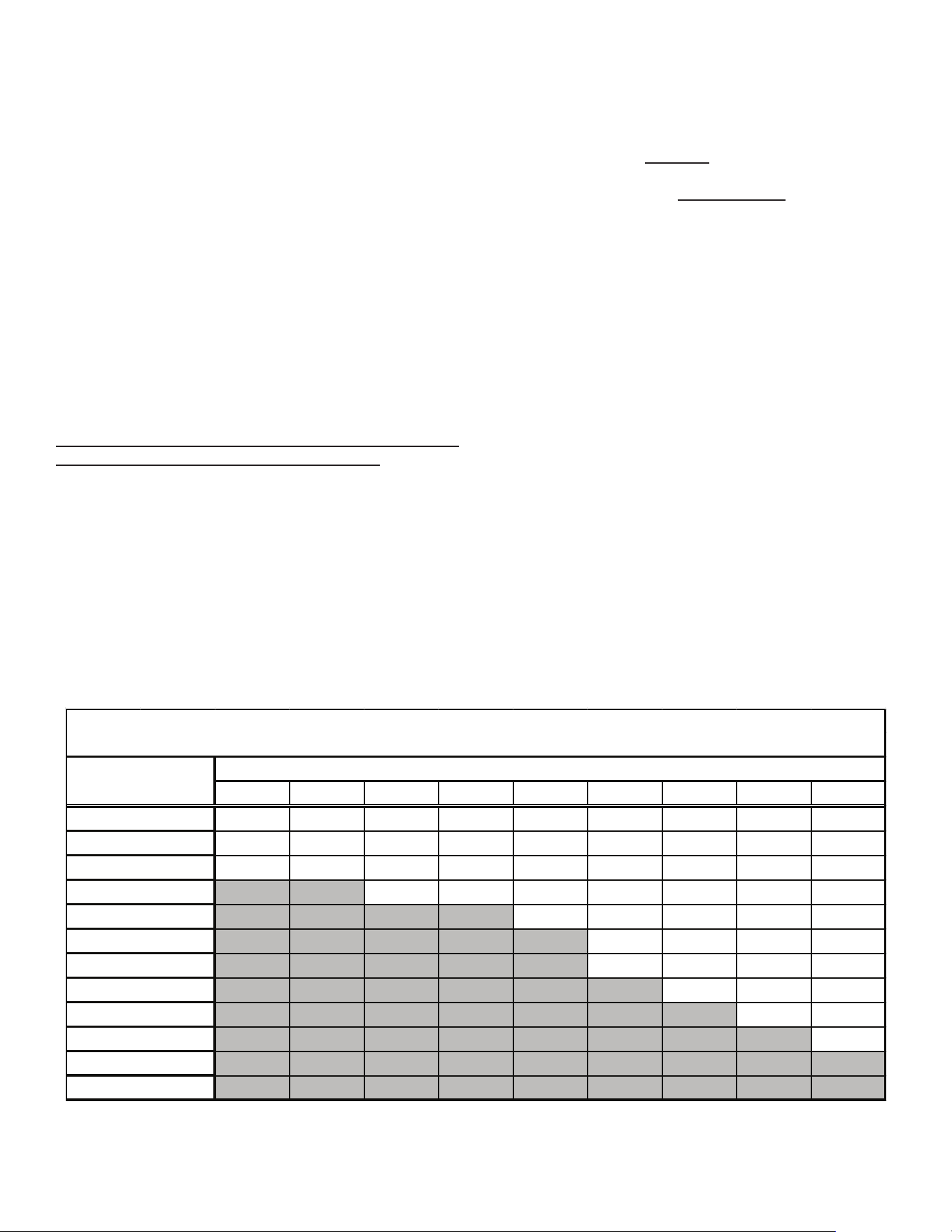
37
SERVICING
1. 3/8” valve to 5 - 10 in-lbs
2. 5/8” valve to 5 - 20 in-lbs
3. 3/4” valve to 5 - 20 in-lbs
4. 7/8” valve to 5 - 20 in-lbs
Do not introduce liquid refrigerant from the cylinder into
the crankcase of the compressor as this may damage the
compressor.
1. Break vacuum by fully opening liquid and suction base
valves.
2. Set thermostat to call for cooling. Check indoor and
outdoor fan operation and allow system to stabilize
for 10 minutes for xed orices and 10-15 minutes for
expansion valves.
Final Charge Adjustment
Airow and Total Static Pressure for the indoor unit should
be veried before attempting to charge system.
1. Total static pressure is .5” WC or less.
2. Airow is correct for installed unit.
3. Airow tables are in the installation manual and Spec
Sheet for Indoor Unit.
4. Complete charging information are in Service Manual
RS6200006.
NOTE: Superheat adjustments should not be made
until indoor ambient conditions have stabilized.
This could take up to 24 hours depending on indoor
temperature and humidity. Before checking superheat
run the unit in cooling for 10-15 minutes or until
refrigerant pressures stabilize. Use the following
guidelines and methods to check unit operation and
ensure that the refrigerant charge is within limits.
The outdoor temperature must be 60°F or higher. Set the
room thermostat to COOL, fan switch to AUTO, and set the
temperature control well below room temperature.
Units matched with indoor coils equipped with a non-
adjustable TXV should be charged by Subcooling only.
Superheat on indoor coils with adjustable TXV valves are
factory set and no adjustment is normally required during
startup. Only in unique applications due to refrigerant
line length, dierences in height between the indoor
and outdoor unit and refrigerant tubing sizes or poor
performance should Superheat setting require adjustment.
These adjustments should only be performed by
qualied service personnel. For detailed charge and TXV
adjustments refer to the appropriate Service Manual.
55 57 59 61 63 65 67 69 71
10 13 17 20 23 26 29 30 31
8 11 14 16 19 22 26 27 29
5 8 10 13 15 19 23 24 25
--- --- 6 9 11 15 20 21 23
--- --- --- --- 7 12 17 18 20
--- --- --- --- --- 8 13 15 16
--- --- --- --- --- 7 10 11 13
--- --- --- --- --- --- 7 8 10
--- --- --- --- --- --- --- 7 8
--- --- --- --- --- --- --- --- 7
--- --- --- --- --- --- --- --- ---
--- --- --- --- --- --- --- --- ---
105
110
115
75
80
85
90
95
100
System Superheat Targets for Piston Match-ups (+/- 1.0 °F)
Indoor Wet Bulb Temperature, °F
Outdoor Dry Bulb
Temperature, °F
60
65
70
Superheat Formula = Suct. Line Temp. - Sat. Suct. Temp.
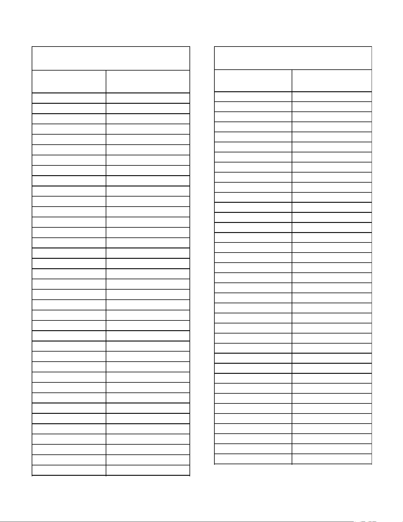
38
SERVICING
NOTE: Specications And Performance Data Listed Herein Are Subject To Change Without Notice.
SUCTION
PRESSURE
SATURATED SUCTION
TEMPERATURE ºF
PSIG R-32
40 -7
42 -6
44 -4
48 -1
50 1
52 2
54 4
56 5
58 6
60 8
62 9
64 10
66 12
68 13
70 14
72 15
74 17
76 18
78 19
80 20
85 23
90 25
95 28
100 30
105 33
110 35
115 37
120 40
125 42
130 44
135 46
140 48
145 50
150 52
155 53
160 55
165 57
170 59
SATURATED SUCTION PRESSURE
TEMPERATURE CHART
LIQUID
PRESSURE
SATURATED SUCTION
TEMPERATURE ºF
PSIG R-32
200 68
210 71
220 74
230 77
240 80
250 82
260 85
270 87
280 90
290 92
300 94
310 97
320 99
330 101
340 103
350 105
360 107
370 109
380 111
390 113
400 115
410 117
420 118
430 120
440 122
450 124
460 125
470 127
480 128
490 130
500 132
525 135
550 139
575 143
600 146
625 150
650 153
675 156
SATURATED LIQUID PRESSURE
TEMPERATURE CHART
39
SERVICING
Fixed Orice
1. Purge gauge lines. Connect service gauge manifold
to base-valve service ports. Run system at least 10
minutes to allow pressure to stabilize.
2. Temporarily install a thermometer 4-6” from
the compressor on the suction line. Ensure the
thermometer makes adequate contact and is insulated
for best possible readings. Use vapor temperature to
determine superheat.
3. Refer to the superheat table provided for proper
system superheat. Add charge to lower superheat or
recover charge to raise superheat.
4. Disconnect manifold set, installation is complete.
Superheat Formula = Suct. Line Temp. - Sat. Suct.
Temp.
Expansion Valve System
NOTE: Units matched with indoor coils equipped with a
TXV should be charged by Subcooling only.
SUBCOOLING FORMULA = SATURATED LIQUID LINE
TEMPERATURE - LIQUID LINE TEMPERATURE
NOTE: for two-stage models, unit will need to be
charged at low stage.
1. Purge gauge lines. Connect service gauge manifold
to base-valve service ports. Run system at least 10
minutes to allow pressure to stabilize.
2. Clamp a pipe clamp thermometer on the liquid line
near the liquid line service valve and 4-6” from the
compressor on the suction line.
a. Ensure the thermometer makes adequate contact
to obtain the best possible readings.
b. The temperature read with the thermometer
should be lower than the saturated condensing
temperature.
3. The dierence between the measured saturated
condensing temperature and the liquid line
temperature is the liquid Subcooling value.
4. TXV-based systems should have a Subcooling value
of 8°F +/- 1°F.
5. Add refrigerant to increase Subcooling and remove
refrigerant to decrease Subcooling.
NOTE: Units matched with indoor coils equipped with a
TXV should be charged by Subcooling only. Superheat
can also be utilized to best verify charge levels with an
adjustable TXV and make adjustments when needed
in unique applications due to refrigerant line length,
dierences in height between the indoor and outdoor
unit and refrigerant tubing sizes. These adjustments
should only be performed by qualied service
personnel.
Superheat Adjustment
NOTE: Units matched with indoor coils equipped with a
TXV should be charged by Subcooling only.
SUPERHEAT FORMULA = SUCTION LINE
TEMPERATURE - SATURATED SUCTION
TEMPERATURE
NOTE: for two-stage models, unit will need to be
charged at low stage.
1. Clamp a pipe clamp thermometer near the suction line
4-6” from the compressor on the suction line.
a. Ensure the thermometer makes adequate contact
for the best possible readings.
b. The temperature read with the thermometer should
be higher than the saturated suction temperature.
2. The dierence between the measured saturated
suction temperature and the suction line temperature
is the Superheat value.
3. TXV-based systems should have a Superheat value
as shown in the table below.
4. Adjust Superheat by turning the TXV valve stem
clockwise to increase and counterclockwise to
decrease.
a. If Subcooling and Superheat are low, adjust the
TXV to the superheat setting specied in the table
below and then check Subcooling.
b. If Subcooling is low and Superheat is high, add
charge to raise Subcooling to 8°F +/- 1°F then
check Superheat.
c. If Subcooling and Superheat are high, adjust the
TXV valve to the superheat specied in the table
below then check the Subcooling value.
d. If Subcooling is high and Superheat is low, adjust
the TXV valve to the superheat specied in the table
below and remove charge to lower the Subcooling
to 8°F +/- 1°F.
NOTE: DO NOT adjust the charge based exclusively
on suction pressure unless for general charging in the
case of a gross undercharge.
NOTE: Check the Schrader ports for leaks and tighten
valve cores if necessary. Install caps nger-tight.
40
SERVICING
Tonnage SH at Compressor
SC at
OD Liq
1.5-2.5T 10-14°F 7-9°F
3.0-5.0T 9-11°F 7-9°F
Superheat Settings for Expansion Valve Systems
Superheat setting for TXV systems for GLXS4B, ALXS4B, and
ALXS4N family
Tonnage SH at Compressor
SC at
OD Liq
1.5-2.5T 10-14°F 7-9°F
3.0-5.0T
10-12°F 7-9°F
Superheat Settings for Expansion Valve Systems
Superheat setting for TXV systems for GLXS3B, ALXS3B, and
ALXS3N family
Tonnage SH at Compressor
SC at OD Liquid
1.5T-4.0T 10-12°F 7-9°F
5.0T 10-12°F 5-7°F
Superheat Se�ngs for Expansion Valve Systems
Superheat / Subcool Setting for TXV systems for
GLXS5BA and ALXS5BA
Heat Pump - Heating Cycle
The proper method of charging a heat pump in the heat
mode is by weight with the additional charge adjustments
for line size, line length, and other system components. For
best results, on outdoor units with TXVs, superheat should
be 8°F +/- 1°F at 4-6” from the compressor. Make nal
charge adjustments in the cooling cycle. Ensure the charge
label has been lled out when nal charging is complete.
Follow directions in the System Startup section. A nal leak
test is recommended before leaving the site of installation.
When servicing is complete, the red valve caps that are
supplied on the valves must be reinstalled nger-tight on
the liquid valve, vapor valve, and access port.
NOTE: Maximum refrigerant charge permissible in the
system can be found on the Evaporator serial plate.
Checking Compressor Eciency
The reason for compressor ineciency is broken or
damaged scroll anks on Scroll compressors, reducing the
ability of the compressor to pump refrigerant vapor.
The condition of the scroll anks is checked in the following
manner.
1. Attach gauges to the high and low side of the system.
2. Start the system and run a “Cooling Performance Test.
If the test shows:
a. Below normal high side pressure.
b. Above normal low side pressure.
c. Low temperature dierence across coil.
d. Low amp draw at compressor.
And the charge is correct. The compressor is faulty -
replace the compressor.
Overfeeding
Overfeeding by the expansion valve results in high suction
pressure, cold suction line, and possible liquid slugging of
the compressor.
If these symptoms are observed:
1. Check for an overcharged unit by referring to the
cooling performance charts in the servicing section.
2. Check the operation of the power element in the valve
as explained in Checking Expansion Valve Operation.
3. Check for restricted or plugged equalizer tube.
Underfeeding
Underfeeding by the expansion valve results in low system
capacity and low suction pressures.
If these symptoms are observed:
1. Check for a restricted liquid line or drier. A restriction
will be indicated by a temperature drop across the drier.
2. Check the operation of the power element of the valve
as described in Checking Expansion Valve Operation.
Checking Expansion Valve Operation
1. Remove the remote bulb of the expansion valve from
the suction line.
2. Start the system and cool the bulb in a container of
ice water, closing the valve. As you cool the bulb,
the suction pressure should fall and the suction
temperature will rise.
3. Next warm the bulb in your hand. As you warm the
bulb, the suction pressure should rise and the suction
temperature will fall.
4. If a temperature or pressure change is noticed, the
expansion valve is operating. If no change is noticed,
the valve is restricted, the power element is faulty, or
the equalizer tube is plugged.
5. Capture the charge, replace the valve and drier,
evacuate and recharge.
41
SERVICING
Checking Restricted Liquid Line
When the system is operating, the liquid line is warm to the
touch. If the liquid line is restricted, a denite temperature
drop will be noticed at the point of restriction. In severe
cases, frost will form at the restriction and extend down the
line in the direction of the ow.
Discharge and suction pressures will be low, giving the
appearance of an undercharged unit. However, the unit will
have normal to high subcooling.
Locate the restriction, replace the restricted part, replace
drier, evacuate and recharge.
Overcharge Of Refrigerant
An overcharge of refrigerant is normally indicated by an
excessively high head pressure.
An evaporator coil, using an expansion valve metering
device, will basically modulate and control a ooded
evaporator and prevent liquid return to the compressor.
An evaporator coil, using a capillary tube metering device,
could allow refrigerant to return to the compressor under
extreme overcharge conditions. Also with a capillary tube
metering device, extreme cases of insucient indoor air
can cause icing of the indoor coil and liquid return to the
compressor, but the head pressure would be lower.
There are other causes for high head pressure which may
be found in the “Service Problem Analysis Guide”.
If other causes check out normal, an overcharge or a
system containing non-condensables would be indicated.
If this system is observed:
1. Start the system.
2. Remove and capture small quantities of gas from the
suction line dill valve until the head pressure is reduced
to normal.
3. Observe the system while running a cooling
performance test. If a shortage of refrigerant is
indicated, then the system contains non-condensables.
Non-Condensables
If non-condensables are suspected, shut down the system
and allow the pressures to equalize. Wait at least 15
minutes. Compare the pressure to the temperature of the
coldest coil since this is where most of the refrigerant will
be. If the pressure indicates a higher temperature than that
of the coil temperature, non-condensables are present.
Non-condensables are removed from the system by rst
removing the refrigerant charge, replacing and/or installing
liquid line drier, evacuating and recharging.
Checking Compressor Eciency
The reason for compressor ineciency is broken or
damaged scroll anks on Scroll compressors, reducing the
ability of the compressor to pump refrigerant vapor. The
condition of the scroll anks is checked in the following
manner.
1. Attach gauges to the high and low side of the system.
2. Start the system and run a “Cooling Performance Test.
If the test shows:
a. Below normal high side pressure.
b. Above normal low side pressure.
c. Low temperature dierence across coil.
d. Low amp draw at compressor.
And the charge is correct. The compressor is faulty –
replace the compressor.
Compressor Burnout
When a compressor burns out, high temperature develops
causing the refrigerant, oil and motor insulation to
decompose forming acids and sludge.
If a compressor is suspected of being burned-out, attach
a refrigerant hose to the liquid line dill valve and properly
remove and dispose of the refrigerant.
NOTICE: Violation of EPA regulations may result in
nes or other penalties.
Now determine if a burn out has actually occurred. Conrm
by analyzing an oil sample using a Sporlan Acid Test Kit,
AK-3 or its equivalent.
Remove the compressor and obtain an oil sample from the
suction stub. If the oil is not acidic, either a burnout has not
occurred or the burnout is so mild that a complete clean-up
is not necessary.
If acid level is unacceptable, the system must be cleaned
by using the clean-up drier method.
CAUTION
Do not allow the sludge or oil to contact the skin. Severe
burns may result.
NOTE: The Flushing Method using R-11 refrigerant
is no longer approved by Amana® Brand Heating-
Cooling.

42
SERVICING
Suction Line Drier Clean-Up Method
The POE oils used with R32 refrigerant is an excellent
solvent. In the case of a burnout, the POE oils will remove
any burnout residue left in the system. If not captured by
the refrigerant lter, they will collect in the compressor
or other system components, causing a failure of the
replacement compressor and/or spread contaminants
throughout the system, damaging additional components.
Install a eld supplied suction line drier. This drier should
be installed as close to the compressor suction tting as
possible. The lter must be accessible and be rechecked
for pressure drop after the system has operated for a
time. It may be necessary to use new tubing and form as
required.
NOTE: At least twelve (12) inches of the suction line
immediately out of the compressor stub must be
discarded due to burned residue and contaminates.
1. Remove compressor discharge line strainer.
2. Remove the liquid line drier and expansion valve.
3. Purge all remaining components with dry nitrogen or
carbon dioxide until clean.
4. Install new components including liquid line drier.
5. Braze all joints, leak test, evacuate, and recharge
system.
6. Start up the unit and record the pressure drop across
the drier.
7. Continue to run the system for a minimum of twelve
(12) hours and recheck the pressure drop across the
drier. Pressure drop should not exceed 6 PSIG.
8. Continue to run the system for several days, repeatedly
checking pressure drop across the suction line drier. If
the pressure drop never exceeds the 6 PSIG, the drier
has trapped the contaminants. Remove the suction line
drier from the system.
9. If the pressure drop becomes greater, then it must be
replaced and steps 5 through 9 repeated until it does
not exceed 6 PSIG.
NOTICE: Regardless, the cause for burnout must be
determined and corrected before the new compressor
is started.
Refrigerant Piping
The piping of a refrigeration system is very important in
relation to system capacity, proper oil return to compressor,
pumping rate of compressor and cooling performance of
the evaporator.
POE oils maintain a consistent viscosity over a large
temperature range which aids in the oil return to the
compressor; however, there will be some installations
which require oil return traps. These installations should
be avoided whenever possible, as adding oil traps to the
refrigerant lines also increases the opportunity for debris
and moisture to be introduced into the system. Avoid long
running traps in horizontal suction line.
Duct Static Pressures
This minimum and maximum allowable duct static pressure
for the indoor sections are found in the specications
section.
Tables are also provided for each coil, listing quantity of air
(CFM) versus static pressure drop across the coil.
Too great an external static pressure will result in
insucient air that can cause icing of the coil. Too much
air can cause poor humidity control and condensate to be
pulled o the evaporator coil causing condensate leakage.
Too much air can also cause motor overloading and in
many cases this constitutes a poorly designed system.
Single Piece Air Handler External Static
To determine proper airow, proceed as follows:
1. Using a Inclined Manometer or Magnehelic gauge,
measure the static pressure of the return duct at the
inlet of the air handler, this will be a negative pressure
(For Example: .30” wc).
2. Measure the static pressure of the supply duct at
the outlet of the air handler, this should be a positive
pressure (For Example: .20” wc).
3. Add the two readings together (For Example: .30” wc +
.20” wc = .50” wc total external static pressure).
NOTE: Both readings may be taken simultaneously and
read directly on the manometer if so desired.
4. Consult proper air handler airow chart for quantity of
air (CFM) at the measured external static pressure.
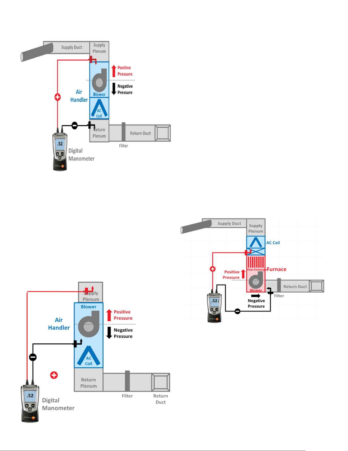
43
SERVICING
Two Piece Air Handler External Static Pressure
To determine proper airow, proceed as follows:
1. Using a Inclined Manometer or Magnehelic gauge,
measure the static pressure between the outlet of the
evaporator coil and the inlet of the air handler, this will
be a negative pressure (For Example: .30” wc).
2. Measure the static pressure of the supply duct at the
outlet of the unit, this should be a positive pressure
(For Example: .20” wc).
3. Add the two readings together (For Example: .30” wc +
.20” wc = .50” wc total static pressure).
NOTE: Both readings may be taken simultaneously and
read directly on the manometer if so desired.
4. Consult proper air handler airow chart for quantity of
air (CFM) at the measured external static pressure.
Furnace External Static Pressure
To determine proper airow, proceed as follows:
1. With clean lters in the furnace, using a Inclined
Manometer or Magnehelic gauge measure the static
pressure of the return duct at the inlet of the furnace
(Negative Pressure).
2. Measure the static pressure between the furnace and
the inlet of the evaporator coil (Positive Pressure). The
limit switch can be removed, and probe inserted to
obtain this reading.
3. Add the two (2) readings together for total external
static pressure.
NOTE: Both readings may be taken simultaneously and
read directly on the manometer if so desired. If high
Eciency Air Filter or Electronic Air Cleaner is used in
conjunction with the furnace, the readings must also
include these components, as shown in the following
drawing.
4. Consult proper airow tables for the quantity of air
(CFM).
If the total external static pressure exceeds the minimum
or maximum allowable statics, check for closed dampers,
registers, undersized and/or oversized poorly laid out
ductwork.
Static Pressure Drop
Periodic Maintenance
Motors
Indoor and Outdoor motors are permanently lubricated and
do not need additional oiling.
Cleaning Outdoor Coil
1. Check for oil deposits on coil this could be an indication
of possible leak. If no leak detected spray coil with
ordinary household detergent.

44
SERVICING
2. Using garden hose, spray coil vertically downward with
constant stream of water at moderate pressure. Keep
nozzle at a 15 to 20° angle, about 3 in. from coil face.
Spray so debris is washed out of coil and base pan.
3. Reinstall top cover and position blade.
4. Reconnect electrical power and check for proper
operation.
Cleaning Outdoor Fan Blade
1. Check balance weights on fan blade.
2. Check fan blade setscrew for tightness.
Electrical Controls and Wiring
1. Disconnect power to both outdoor and indoor units.
2. Check all electrical connections for tightness.
3. Tighten all screws on electrical connections.
4. Connections that appear to be burned or smoky should
be disassembled and cleaned all parts
5. Wire connections that appear burned and corroded
should be replaced and crimp tightly to assure they do
not overheat.
6. Reconnect electrical power to indoor and outdoor units
and check for proper operation.
Cleaning Aluminum Coils
Evaporator coils and air handlers are equipped with an
aluminum tube evaporator coil. The safest way to clean the
evaporator coil is to simply ush the coil with water. This
cleaning practice remains as the recommended cleaning
method for both copper tube and aluminum tube residential
cooling coils.
An alternate cleaning method is to use one of the products
listed in the technical publication TP-109 (shipped in the
literature bag with the unit) to clean the coils. The cleaners
listed are the only agents deemed safe and approved for
use to clean round tube aluminum coils. TP-109 is available
on the web site in Partner Link > Service Toolkit.
NOTE: Ensure coils are rinsed well after use of any
chemical cleaners
System Service and Decommissioning
Should repairs requiring recovery of the refrigerant
become necessary, special considerations must be made
when breaking into systems with ammable refrigerants.
These repairs shall only be performed by qualied service
personnel and in compliance with local and national
regulations.
The refrigerant charge shall only be recovered into
a cylinder labeled for use with R-32. Ensure that the
refrigerant cylinder(s) are capable of holding the total
system charge. Cylinders shall be complete with a
pressure-relief valve and associated shut-o valves in good
working order. Empty recovery cylinders are evacuated
and, if possible, cooled before recovery occurs. A set of
calibrated weighing scales shall be available and in good
working order. Hoses shall be complete with leak-free
disconnect couplings and in good condition.
All best practices for refrigerant recovery must be followed,
including use of a recovery machine designated safe for
use with A2L refrigerants. Isolate the system electrically
prior to recovery. Ensure that all personal protective
equipment is being applied correctly. Ensure that the
recovery process is supervised at all times by the qualied
servicer. Situate the R-32 cylinder on the scale before
recovery takes place. Start the recovery machine and
operate in accordance with its instructions. Do not overll
cylinders by more than 80% volume of its allowed liquid
charge.
Should electrical components need to be replaced,
ensure that the original equipment manufacturer’s part or
equivalent is used.
Markings and warnings on the unit shall continue to be
visible and legible after installation and service. Correct any
markings and warnings that are made illegible.
When decommissioning a system, all previously mentioned
precautions regarding safe refrigerant handling must be
followed. Recovered refrigerant shall not be charged into
another refrigerating system unless it has been cleaned
and checked. Equipment must be labeled, dated, and
signed stating that it has been decommissioned and
emptied of refrigerant.
Decommissioning
Before carrying out this procedure, it is essential that the
technician is completely familiar with the
equipment and all its detail. It is recommended good
practice that all refrigerants are recovered safely.
Prior to the task being carried out, an oil and refrigerant
sample shall be taken in case analysis is required
prior to re-use of recovered refrigerant. It is essential that
electrical power is available before the task is
commenced.
a. Become familiar with the equipment and its operation.
b. Isolate system electrically.
c. Before attempting the procedure, ensure that:
• mechanical handling equipment is available, if
required, for handling refrigerant cylinders;
• all personal protective equipment is available and
being used correctly;
• the recovery process is supervised at all times by a
competent person;

45
SERVICING
• recovery equipment and cylinders conform to the
appropriate standards.
d. Pump down refrigerant system, if possible.
e. If a vacuum is not possible, make a manifold so that
refrigerant can be removed from various parts of the
system.
f. Make sure that cylinder is situated on the scales before
recovery takes place.
g. Start the recovery machine and operate in accordance
with instructions.
h. Do not overll cylinders (no more than 80 % volume
liquid charge).
i. Do not exceed the maximum working pressure of the
cylinder, even temporarily.
j. When the cylinders have been lled correctly and the
process completed, make sure that the cylinders and
the equipment are removed from site promptly and all
isolation valves on the equipment are closed o.
k. Recovered refrigerant shall not be charged into another
REFRIGERATING SYSTEM unless it has been
cleaned and checked.
Labelling of Equipment
Equipment shall be labelled stating that it has been de-
commissioned and emptied of refrigerant. The label
shall be dated and signed. For appliances containing
FLAMMABLE REFRIGERANTS, ensure that there are
labels on the equipment stating the equipment contains
FLAMMABLE REFRIGERANT.
46
Troubleshooting Air Handler - EEM Motor
No
Yes
No
240 volts at EEM
motor on terminals
L & N
Check breaker or fuses and
wiring
Check for 24 volts
between C & and
T1-T5/T6-T9 terminals
at the motor
Make sure thermostat is calling
for fan operation. Check low
voltage fuse and wiring.
Replace faulty EEM motor or
module
Yes
EEM Motor Equipped
Air Handler
Check module and motor
as per service manual
47
Troubleshooting Auxiliary Electric - Heating
No
No Heat
No
No
240 Volts at
Breakers or
Contactors
Check indoor Panel
Replace breaker or wiring
Replace Transformer
Yes
No
Replace Fusible Links
Yes
Check Line Voltage
on Contactor(s)
Check for open limit switch. If
open replace limit.
No
Check Power
at Disconnect
Yes
Check wiring
to Breaker or
Contactor
Check Thermostat and Wiring
24 Volts at
transformer
Check Thermostat and Wiring
24 Volts on W
at contactor
Check 24 Volts
on Contactor(s)
Yes
No
No
No
No
Check Breakers or Fuses
Replace Contactor(s)
Contactor(s)
Closed
Yes
Replace Electric Heat Strips
Yes
Fusible links
Closed
No
Ohm Heat
strips if no
continuity
Yes
Yes
Yes
Proceed to low voltage check
Yes
48
Troubleshooting Condenser - Cooling
No
Yes
No Cool
No
No
Compressor
Running
Repair or Replace Wiring
Replace Capacitor
Check for Locked Compressor
Check Refrigerant Charge and
Amp Draw
Replace Compressor
Yes
No
Replace Contactor
Yes
No
Check for clogged piston or
faulty TXV. See service manual
for procedure.
Metering Device
Working Properly
Check Thermostat and
Thermostat Wires
Check Control Board no Voltage
out of Board replace Board
No
Replace Motor
Contactor
Open
Wiring to
Compressor
Replace Compressor
Replace Compressor
230 Volts to
Unit
Check Breakers or Fuses
Yes
230 Volts to
Transformer
Check Wiring from Contractor to
Transformer
Yes
24 Volts from
Transformer
Yes
24 Volts on Y
from
Thermostat
Yes
24 Volts to
Contactor Coil
Yes
No
No
No
No
No
No
Yes
No
Yes
Run Capacitor
Good
Compressor
Overload
Open
Compressor
Windings
Open
Compressor
Warm to
Touch
Did Compressor
Restart After
Allowing to Cool
Yes
No No
No
Yes
Yes
Yes
Check Pressure Switches and
Wiring
Check Thermostat and
Thermostat Wiring
Replace Transformer
Compressor
Pumping
Yes
Replace Compressor
Indoor Blower
Running
No No
Voltage to
Indoor Motor
Yes
24 Volts on G
from
Thermostat
Yes
Check for proper charge. Check
subcooling and/or superheat.
Yes
49
Troubleshooting Heat Pump - Cooling (1 Stage)
No
Yes
No Cool
NoNo
Yes
No
Compressor
Running
Repair or Replace Wiring
Replace Capacitor
Check for Stuck Compressor
Check Refrigerant Charge and
Amp Draw
Replace Compressor
Yes
No
Replace Contactor
Yes
Reversing Valve
Stuck Between
Heat and Cool
No
Repair or Replace Metering
Device
Metering Device
Working Properly
No
Replace Reversing Vlave
Check Thermostat and
Thermostat Wires
Check Indoor Blower Replay
and Control Wiring in Unit
No
Replace Indoor Motor
Yes
No
Contactor
Open
Wiring to
Compressor
OK
Yes
Run Capacitor
Good
Compressor
Overload
Open
Compressor
Windings
Open
Replace Compressor
Compressor
Warm to
Touch
Did Compressor
Restart After
Allowing to Cool
Yes
Replace Compressor
230 Volts to
Unit
Check Breakers or Fuses
Yes
230 Volts to
Transformer
Check Wiring from Contractor to
Transformer
Yes
24 Volts from
Transformer
Yes
24 Volts on Y
from
Thermostat
Yes
24 Volts to
Contactor Coil
Yes
No
No
No
No
No
No No
No
No
Yes
Yes
Yes
Check Pressure Switches and
Wiring
Check Thermostat and
Thermostat Wiring
Replace Transformer
Compressor
Pumping
Yes
Yes
Replace Compressor
Yes
Indoor Blower
Runnng
No No
Voltage to
Indoor Motor
Yes
24 Volts on G
from
Thermostat
Yes
Reversing
Valve in Cool
Mode
24 Volts to
Reversing Valve
Check thermostat for proper
setting anf function
Check Thermostat and
Thermostat Wires
Reversing
Valve
Solenoid Coil
Good
Yes
Check Internal Wiring to
Reversing Valve
Replace Reversing Valve
Solenoid
Reversing
Valve Piped
Correctly
Replace Reversing Valve
Yes
No
No
No
No
24 Volts on O
from Thermostat
Thermostat in
Cool Mode
Yes
Yes
Yes
Install Reversing Valve Correctly
50
Troubleshooting Heat Pump - Cooling (1 Stage)
Check for proper charge.
Check subcooling and/or
superheat
Yes
Metering Device
Working Properly
Yes
No
Repair or replace Metering
Device
51
Troubleshooting Heat Pump - Heating (1 Stage)
No
Yes
No Heat
NoNo
Yes
Yes
No
Compressor
Running
Repair or Replace Wiring
Replace Capacitor
Check for Stuck Compressor
Check Refrigerant Charge and
Amp Draw
Replace Compressor
Yes
No
Replace Contactor
Yes
Reversing Valve
Stuck Between
Heat and Cool
No
Repair or Replace Metering
Device
Metering Device
Working Properly
No
Replace Reversing Vlave
Check Thermostat and
Thermostat Wires
Check Indoor Blower Replay
and Control Wiring in Unit
No
Replace Indoor Motor
Yes
No
Contactor
Open
Wiring to
Compressor
OK
Yes
Run Capacitor
Good
Compressor
Overload
Open
Compressor
Windings
Open
Replace Compressor
Compressor
Warm to
Touch
Did Compressor
Restart After
Allowing to Cool
Replace Compressor
230 Voltas to
Unit
Check Breakers
Yes
230 Volts to
Transformer
Check Wiring from Contractor to
Transformer
Yes
24 Volts from
Transformer
Yes
24 Volts on Y
from
Thermostat
Yes
24 Volts to
Contactor Coil
Yes
No
No
No
No
No
No No
No
No
Yes
Yes
Yes
Check Pressure Switches and
Wiring
Check Thermostat and
Thermostat Wiring
Replace Transformer
Compressor
Pumping
Yes
Yes
Replace Compressor
Yes
Indoor Blower
Runnng
No No
Voltage to
Indoor Motor
Yes
24 Volts on G
from
Thermostat
Yes
Reversing
Valve in Cool
Mode
Metering Device
Working Properly
Yes
Repair or Replace Metering
Device
Check for proper charge. Check
subcooling and/or superheat
24 Volts to
Reversing
Valve
Reversing Valve
Piped Correctly
Yes
Install Reversing Valve Correctly
Replace Reversing Valve
24 Votls on O
from
Thermostat
Replace Reversing Valve
Yes
Yes
No
No
No
No
52
Troubleshooting Heat Pump - Heating (1 Stage)
Switch Thermostat to Heat
Mode
Yes
Thermostat in
Cool Mode
Yes
No
Check Thermostat and
Thermostat Wires
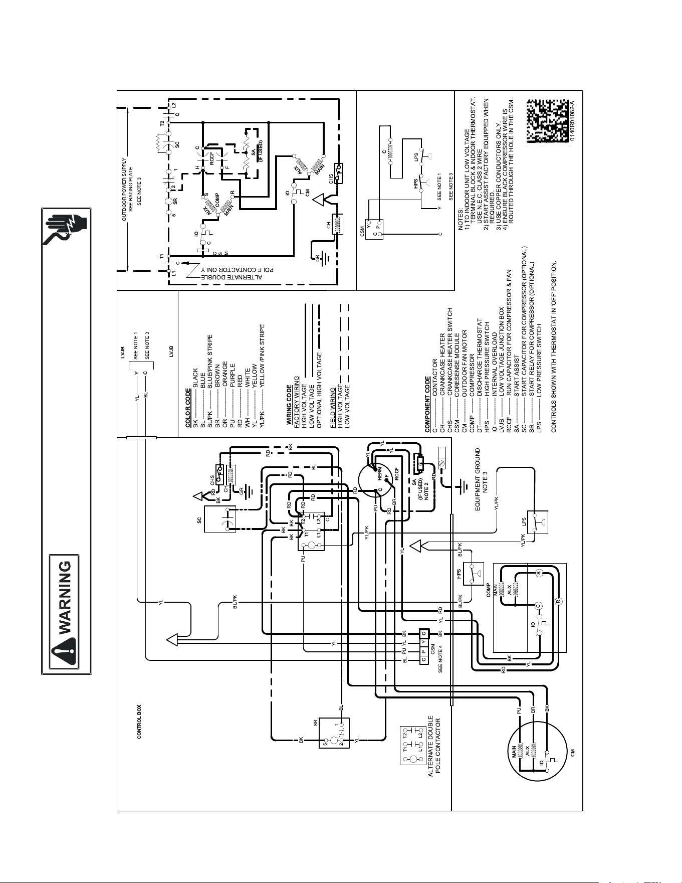
53
WIRING DIAGRAMS
HIGH VOLTAGE!
D
ISCONNECT
ALL
POWER
BEFORE
SERVICING
OR
INSTALLING
THIS
UNIT
.
M
ULTIPLE
POWER
SOURCES
MAY
BE
PRESENT
. F
AILURE
TO
DO
SO
MAY
CAUSE
PROPERTY
DAMAGE
,
PERSONAL
INJURY
OR
DEATH
.
Wiring is subject to change. Always refer to the wiring diagram on the unit for the most up-to-date wiring.
DC3SEN, DC4SEA
012 3
456789467157
3157019640618195
1
6
0
2
4
9
8
4
8
4
800
0
6
0
5
5
7
0
0
2
4
9
4
1
02
0
0
5
0
5
0 0 1 9 6 4 0 6 1 8
0 0 8 4 9 0 4 7 7 4 6 7 8
0 0 8 4 9 0 4 7 7 4 6 7 8 6 0
0 2 0 1 8 7 7 9 7 2 1 5 7
0 2 1 6 1 1 8 4 9 2 1 6 1 8
0 1 2 3 0 1 2 3 8 7 1 8
6 0 4 8 7 6 7 8 2 1 6 4 6
3 38787 60
1 9 6 7 8 9 4 5 1 7 8 5 1 4
5 5 1 1 5 6 4 7 9 0 6 1 9 1
8 0 0 8 9 0 4 3 4 0 6 1 8 1 8 0 1 2 3 8 7 1 8 " 4 9
4648646
06486043406181801238718136 1 9 4 5
86486875418012387181361945
5351 38787 60
01968151 9 6678216469#1#31619$
1611831 78335
778469 35467
%&' & (
4061 8 8 9
1 5 6 4 7
51 1 564 7
1361945 1564 7
7 5 8 9
1 5 6 4 7
51 1 564 7
00
5
0
5
6
5
6
5
800
0
782
5
5
8
3
5
8
5
8
012 3
1
02
4
2 4 9
8
8
5
5
3
5)3
*'
5 4 0
5 5 7
5)357)396837
8 8 1 9
1 8 1 8 4 9 7
3 3 8 3 5 7
8 8 7
6 7
5 7 5 5 1
5 )3 7 5 5 1 )3 9 6 8 3 7
3
9167+
6 1 9 1 1 8 9 6 5 1 1 5 6 4 7
6 7 8 2 9 4 5 5 1 0 " 9 1 1 8 6 7 8 2 1 6 4 6 $
7 9 $7 $0 $0 5 4 8 7
648646406187-337 79
8 7 - 8 7 $
.70133780190618195$
/7987540012 38718 87
8 1 6 7 6 8 1 6 7 1 5 7 9 6 7 0 2 $
8
4
7
9 1 6 7
2 4 9
0
1
8
4
012 3
1
6
0
2
4
9
8
4
8
02
4
800
0
6
0
5
5
7
0
0
0
2
2
4
9
4
1
02
0
0
0
5
0
5
7 7 9 1 6 7
7 7 9 1 6 7 .
0
3
0
02
*0 12
'*23
0
0
6
5
6
5
800
0
782
8
8
3
5
8
5
8
012 3
1
02
4
2 4 9
8
7-32 796 819
3
5)3
3
8
4
7
9 1 6 7
9 1 6 7 .
53
0
1
8
4
53
5
3
5
6
5
6
5
456789467157
3157019640618
5
5)3
7 7 9 1 6 7
7 7 9 1 6 7 .
3
5
5
8
3
8
8
8
8
5
5 )3
779167.
7 7 9 1 6 7 /
0
0
5 )3
8
0
8
0
5)3
3
5
5
8
8
5 )3
4/48 4454
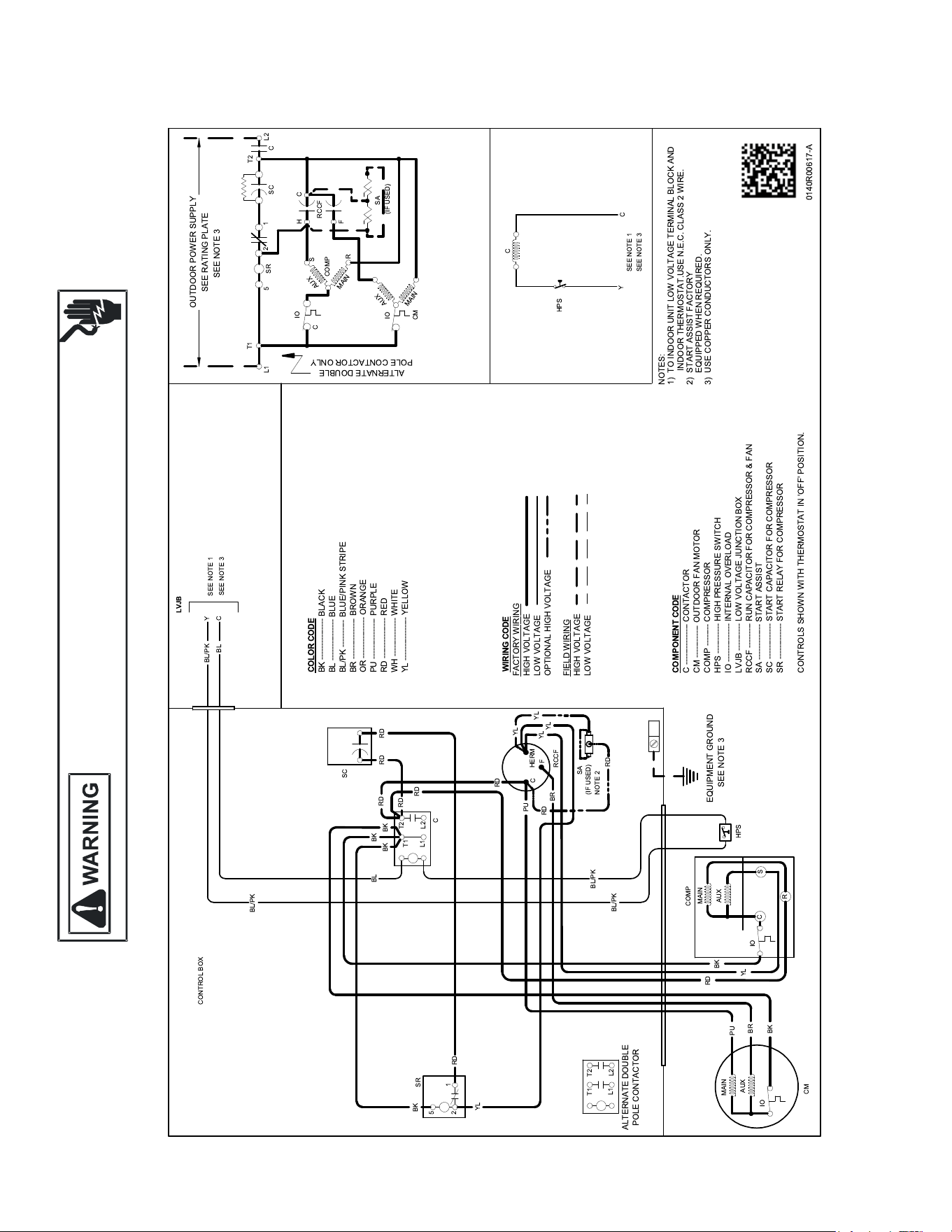
54
WIRING DIAGRAMS
HIGH VOLTAGE!
D
ISCONNECT
ALL
POWER
BEFORE
SERVICING
OR
INSTALLING
THIS
UNIT
.
M
ULTIPLE
POWER
SOURCES
MAY
BE
PRESENT
. F
AILURE
TO
DO
SO
MAY
CAUSE
PROPERTY
DAMAGE
,
PERSONAL
INJURY
OR
DEATH
.
Wiring is subject to change. Always refer to the wiring diagram on the unit for the most up-to-date wiring.
DC3SQN18-30, DC4SQA18-30
012 3
456789467157
3157019640618195
1
6
2
4
9
8
4
8
4
800
0
6
0
5 5
7
0
0
2
4
9
4
0
0
8 4
5
0
" 5 4 0 "
5 5 7
5#3"57#39"6837
8 8 1 $ 9
1 8 1 8 4 9 % 7
3 3 8 3 5 7
8 8 7
$ $ 6 7
5 7 5 5 1 $
01968151
&'( ()
0 0 1 9 6 4 0 6 1 8
0 2 1 6 1 1 8 4 9 2 1 6 1 8
0 1 2 3 0 1 2 3 8 7 1 8
3 % 3 8 7 8 7 $ 6 0
1 9 6 7 8 9 4 5 1 * 7 8 5 1 4
5 * + 5 1 $ * 1 5 6 4 % 7 + 9 0 6 1 9 1
80089043406181801238718-49
4 6 4 8 6 4 6
0 6 4 8 6 0 4 3 4 0 6 1 8 1 8 0 1 2 3 8 7 1 8
8 6 4 8 6 8 7 5 4 1 8 0 1 2 3 8 7 1 8
01968151$ 9$ 6678216469.1.31619/
161 1831$ 78335
778469%35467
0 1 1(2
40618 $89%
%*1564%7
51 $ *1 564% 7
1361945%*1564%7
75 $89%
%*1564%7
51 $ *1 564% 7
1
02
5 #3 "
5
0
8
8
"
4
2 4 9
012 3
7791 67
0
8
8
800
0
782
5
5
5
8
8
3
5
8
8
"
5
8
8
5
8
8
""
"
0
6
5
6
5
8
4
7
9 1 6 7
7332796%819
3
8
"
2 4 9
4
02
1
6
5
6
5
456789467157
3157019640618
91674
6191189651$ *1564%76782 945510"49
9 1 1 8 6 7 8 2 1 6 4 6 / 7 9 /7 /0 /0 5 4 $ 8 7 /
64864640618
73337$ 7987387/
570133780190618195/
5#3"
3
5#3"
3
5#3"
1
7 7 9 1 6 7
7 7 9 1 6 7 5
7791675
7791675
7791675
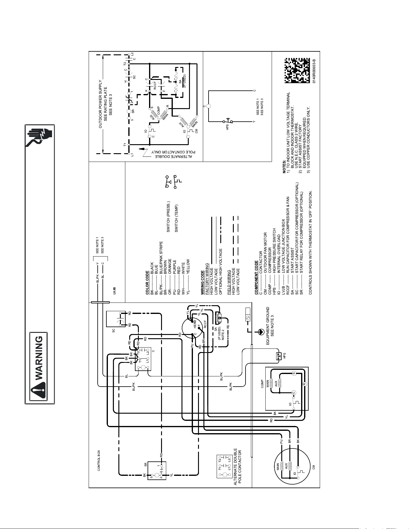
55
WIRING DIAGRAMS
HIGH VOLTAGE!
D
ISCONNECT
ALL
POWER
BEFORE
SERVICING
OR
INSTALLING
THIS
UNIT
.
M
ULTIPLE
POWER
SOURCES
MAY
BE
PRESENT
. F
AILURE
TO
DO
SO
MAY
CAUSE
PROPERTY
DAMAGE
,
PERSONAL
INJURY
OR
DEATH
.
Wiring is subject to change. Always refer to the wiring diagram on the unit for the most up-to-date wiring.
DC3SQN36-60, DC4SQA36-48
0123
456789467157
3157019640618195
6
2
4
9
8
4
8
4
800
0
6
0
5 5
7
0
2
4
9
4
0
0
8
5
0
"
5
5 #3 "
8
1 8
3
8
$
5
01968151
% &' '(
0 0 1 9 6 4 0 6 1 8
0 2 1 6 1 1 8 4 9 2 1 6 1 8
0 1 2 3 0 1 2 3 8 7 1 8
3 ) 3 8 7 8 7 $ 6 0
1 9 6 7 8 9 4 5 1 * 7 8 5 1 4
5*+51$ *1564)7+9061 91
80089043406181801238718-49
4 6 4 8 6 4 6
0 6 4 8 6 0 4 3 4 0 6 1 8 1 8 0 1 2 3 8 7 1 8 1 3 6 1 9 45
8 6 4 8 6 8 7 5 4 1 8 0 1 2 3 8 7 1 8 1 3 6 1 9 4 5
01968151$ 9$ 66782 16469.1.31619/
1611831$ 78335
778469)35467
0 11'2
40618$89)
)*1564)7
51 $ *1 564) 7
1361 945)*1564)7
7
5$89)
)*1564)7
51 $ *1 564) 7
5#3"
5
0
8
8
"
4
2 4 9
0123
779167
0
8
8
800
0
782
5
5
5
8
8
3
5
8
8
"
5
8
8
5
8
8
""
"
0
6
5
6
5
8
4
7
9 1 6 7
7332 796)81 9
7791 67
3
8
"
2 4 9
4
02
1
6
5
6
5
456789467157
3157019640618
' ( 45
6 1 9 1 1 8 9 6 5 1 $ * 1 5 6 4 ) 7 6 7 8 2 9 4 5
510"4991186782 1646/
79/7/0/054$ 87/
6486464061 8
73337$ 7987387/
70133780190618195/
5 #3 "
3
5#3"
3
5#3"
1
779167
779167
779167
779167
0
$ 6 0 3 8 7 /
$ 6 0 6 7 2 3
1
0
1
02
540 "
57
57#39"6837
81$ 9
1849) 7
38357
87
$ 6 7
7551 $
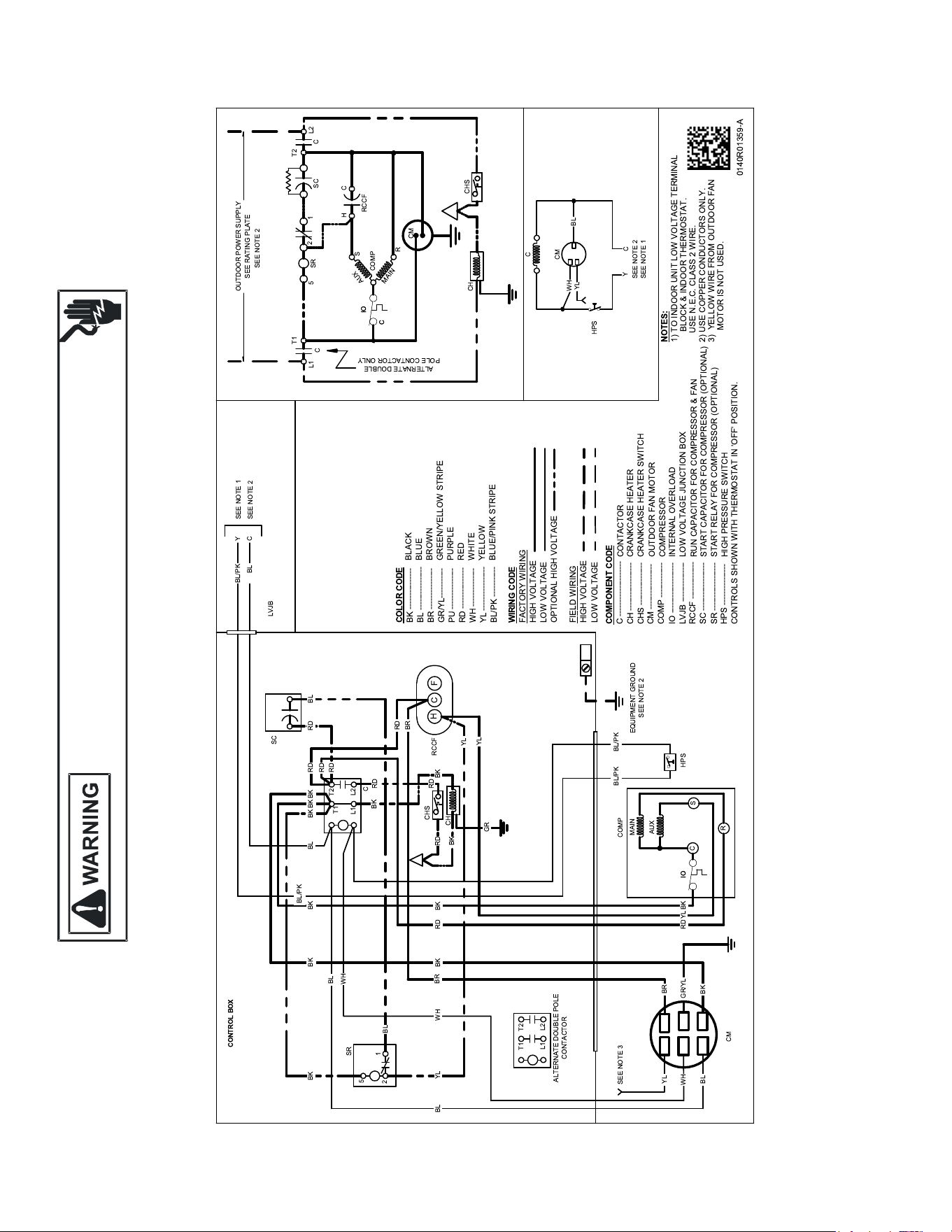
56
WIRING DIAGRAMS
HIGH VOLTAGE!
D
ISCONNECT
ALL
POWER
BEFORE
SERVICING
OR
INSTALLING
THIS
UNIT
.
M
ULTIPLE
POWER
SOURCES
MAY
BE
PRESENT
. F
AILURE
TO
DO
SO
MAY
CAUSE
PROPERTY
DAMAGE
,
PERSONAL
INJURY
OR
DEATH
.
Wiring is subject to change. Always refer to the wiring diagram on the unit for the most up-to-date wiring.
DC4SQA60
012 3
456789467157
3157019640618195
6
0
2
4
9
8
4
8
800
0
6
0
5 5
0
0
0
8 4
0
5
1611831 78335
778469"35467
5 #3 $
0
8
4
2 4 9
0123
7 7 9 1 6 7
0
8 5
800
5
8
8
$
5
5
5
8
0
6
5
6
5
7%32796"819
7791 67
$
6
5
6
5
4567894671573157
019640618
&'(
)6191189651 1564"76 782945
510$*91 186782 1646,
79,7,0,054 87,
)70133780190618195,
) 7 5 5 1 8 7 8 1 2 1 6 1 1 8 4 9
2 1 6 1 8 9 1 6 7 ,
0
8
779167
779167
8
8$$$
779167
0
0
$
8
8
$
"8
0
5#3$
0
$
5
85$
5
$
" 8 # 5
8
5
02
5
5
5
02
02
1
0
1
0
-&
$
5
8
" 8 # 5
3
8
5
5 #3 $
540$
5 7
81 9
"8779#7551 6837
38357
87
6 7
7 551
57#39$6837
. / /0-&
40618 89"
"1564"7
51 1 564" 7
1361945"1564"7
75 89"
"1564"7
51 1 564" 7
12&-&
0
0
0
02
0123
1
5
800
0
8
3
01968151 9 66 7 821646931331619,
019640618
0849$04774678
0849$04774678 60
161184921618
012 38718
9678945178514
51 1564"7906191
890434061818012 38718*49
64860434061818012 3871841361945)
648687541801 23871841361945)
"38787 60
8
5 8
8
$ $
$ $
3
5 #3 $ 5 #3 $
3
7791 67
7 7 9 1 6 7
5
11
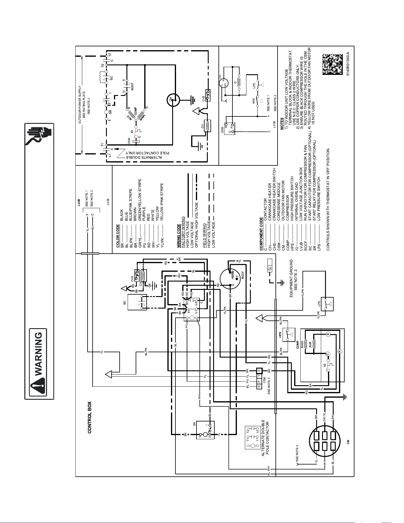
57
WIRING DIAGRAMS
HIGH VOLTAGE!
D
ISCONNECT
ALL
POWER
BEFORE
SERVICING
OR
INSTALLING
THIS
UNIT
.
M
ULTIPLE
POWER
SOURCES
MAY
BE
PRESENT
. F
AILURE
TO
DO
SO
MAY
CAUSE
PROPERTY
DAMAGE
,
PERSONAL
INJURY
OR
DEATH
.
Wiring is subject to change. Always refer to the wiring diagram on the unit for the most up-to-date wiring.
DC4SEA60
0123
456789467157
3157019640618195
1
6
0
2
4
9
4
8
800
0
6
0
5
5
0
0
0
0
5 0
5
0
0
0
0 2
0 2
0 1 2 3
3
1
5
8 0 0
0
8
5 3
01968151 9 6678216469131619
1611831 78335
77846935467
"# "$
40618 89
1 5 6 4 7
51 15647
13619451564 7
75 89
1 5 6 4 7
51 15647
00
5
0
5
6
5
6
5
800
0
782
5
3
8
5
8
%
012 3
02
8
8
5
5
3
5&3%
'#
%
5
5 &3 %
8
8 & 5
3
8
5
5 &3 %
3
(6 1 9 1 1 8 9 6 5 1 1 5 6 4 7
6782 945510%)91186782 1646
7 9 7 0 0 5 4 8 7
(70133780190618195
*(7987540%01238718 87
8 1 6 7 6 8 1 6 7 1 5 7 9 6 7 0 2
+(7551 87812161184921618
9 1 6 7
2 4 9
0
1
8
4
0123
1
6
0
2
4
9
4
8
02
800
0
6
0
5
5
0
0
02
0
0
0
5
0
5
7 7 9 1 6 7
0
3
0
02
'-./
#'/0
0
0
6
5
6
5
800
0
782
8
8
5
8
%
012 3
02
%
8 & 5
7132796819
3
5 &3 %
53
779167
53
0
1
8
4
5
3
5
6
5
6
5
456789467157
3157019640618
5
5&3%
779167
779167
%
3
5
5
8
3
%
%
%
8
8
8
8
5
5&3%
779167
7791 67*
0
0
5&3%
8
0
0
%
5&3%
8
5
%
%
8
8
%
5 &3 %
2+28 2*324
5
5
5
5
5
5
02
02
8
540%
5 7
57&39%6837
81 9
8779&7551 6837
38357
87
6 7
7551
7 5 5 1 &3 9 % 6 8 3 7
019640618
0849%04774678
0849%04774678 60
01877972157
161184921618
01238718
38787 60
9678945178514
51 15647906191
890434061818012 38718)49
648604340618180123871841361945(
6486875418012 3871841361945(
51 38787 60
5
7 7 9 1 6 7
7791 67+
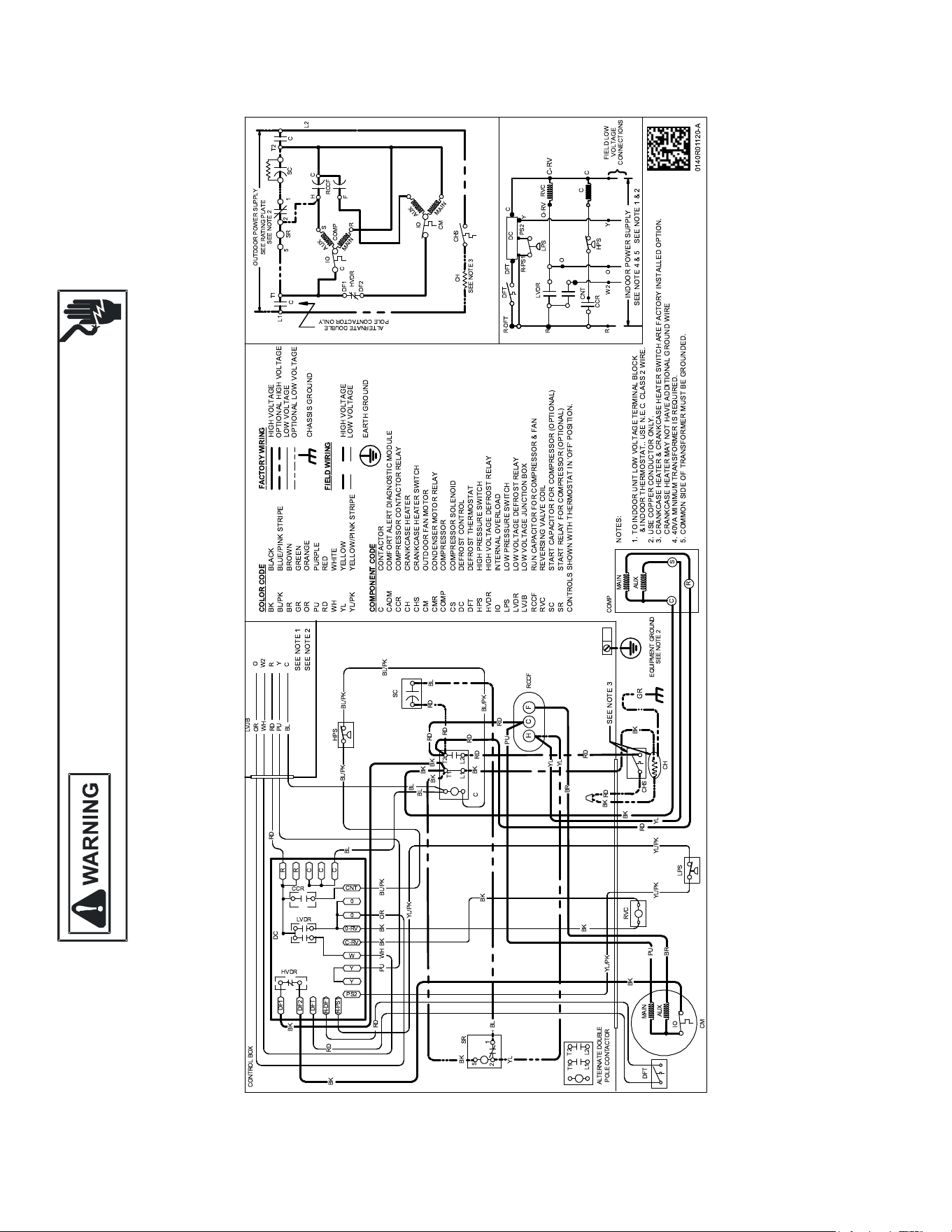
58
WIRING DIAGRAMS
HIGH VOLTAGE!
D
ISCONNECT
ALL
POWER
BEFORE
SERVICING
OR
INSTALLING
THIS
UNIT
.
M
ULTIPLE
POWER
SOURCES
MAY
BE
PRESENT
. F
AILURE
TO
DO
SO
MAY
CAUSE
PROPERTY
DAMAGE
,
PERSONAL
INJURY
OR
DEATH
.
Wiring is subject to change. Always refer to the wiring diagram on the unit for the most up-to-date wiring.
DH4SQA18-60
01233 4637 84966
13 89
30123341037 3884013
01233484 399818997 048
98366843123431
4198884419888497 048340198236031
4198884 13822003143127 04 8
010 41934 8409480482
33190283419348498431282
36
8418238
638313431
03
0
1
4
9
94
4
9
0
1
03
4
!#$
%6 8%60194068
4 437 1
4 4881
34 3418
6 6468
42 482
7 708
83 7
%6 837 %60194068
&' ($() #$
3134
2 33484201390328
4 3 648993 4313448
4198884
9 419888497 0
323341334
4 3128198433448
3 6 3 648993 4
9 3648993493 81302
2 284393143
2 284398439
69 0648994897 0
24 0382843948
03 0184138432
69 3 7 648994897 0
24 37 3 82843 948
* 3 7 3 8* 1 03 1 3
4 416034343 64899341
4 4884901830
9 946034343 648993 4+36031,
94 9448343 648993 4+3 6031,
31439937 17 0843901-3-6390031
32334637 84966
98840168
98813 8
2
2
2 4
4
2
2
2
3
4
7
4
24
4 2
4
69
69
3
4
.
08 2 3 7
38
31180319
98813 8
98813 8
469
34
34
6
42
3
4
*
31433
9
42
42
4
6
42
94
42
69
7
7
42
2
4
42
4 2
42
806814312
98813 8
8418238
6383 134
%6
%6
9
4
9
01
36
4
988138
42
9 8 8 1 3 8
98813 8
42
6
42
42
7
34
%6
988138
01
03
2
4
2
2
4
4
7
2 4
24
4
1
2
42
469
4
69
%6
%6
%6
4
%6%6
%6
69
1
4
6
0 3 8
3 6 03 1 0 3 8
3 7 3 8
3 6 03 1 3 7 3 8
9 9 09 4 3 1 2
0 3 8
3 7 3 8
8 4 4 3 1 2
/0) !1 2 3!3(4
/3$ # 2 3!3(4
69
9
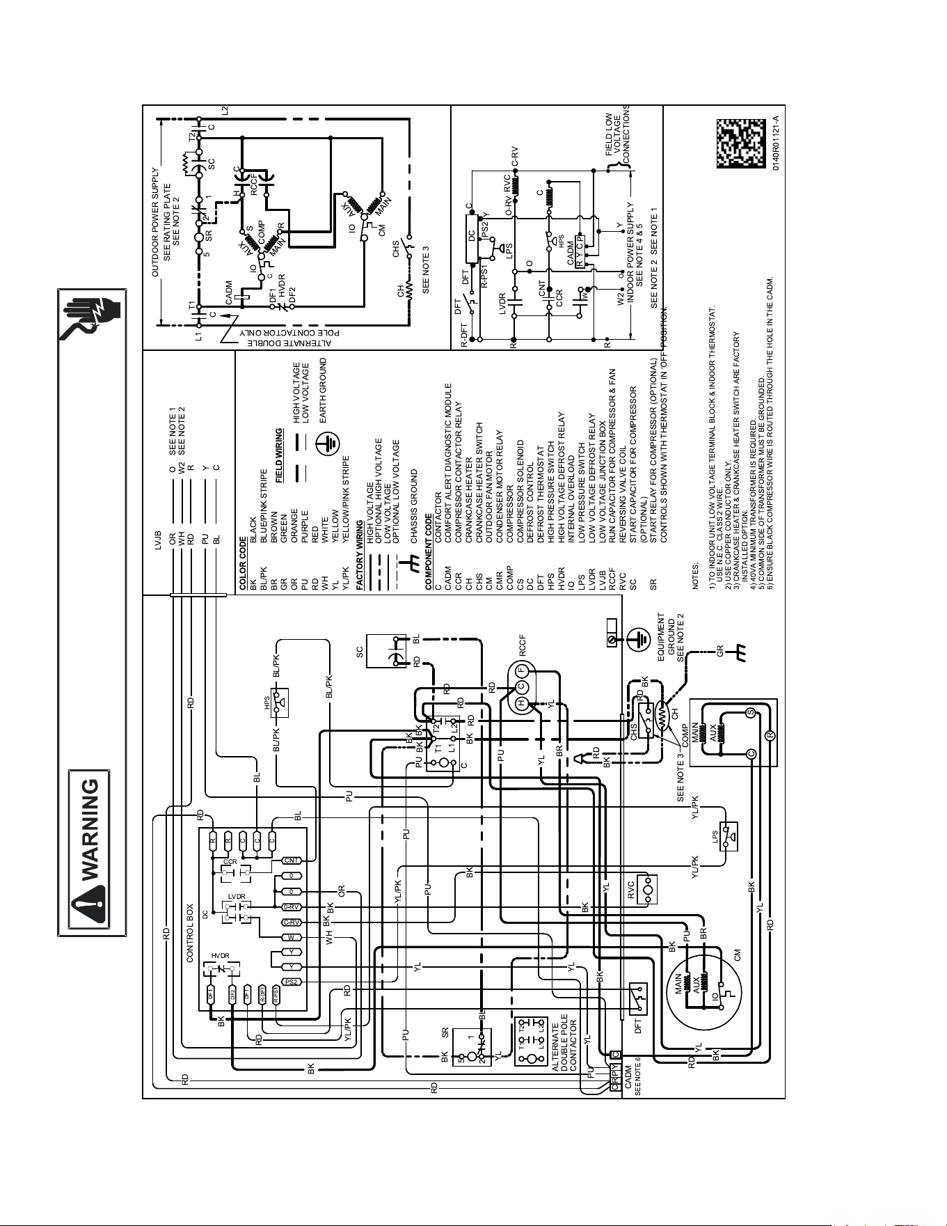
59
WIRING DIAGRAMS
HIGH VOLTAGE!
D
ISCONNECT
ALL
POWER
BEFORE
SERVICING
OR
INSTALLING
THIS
UNIT
.
M
ULTIPLE
POWER
SOURCES
MAY
BE
PRESENT
. F
AILURE
TO
DO
SO
MAY
CAUSE
PROPERTY
DAMAGE
,
PERSONAL
INJURY
OR
DEATH
.
Wiring is subject to change. Always refer to the wiring diagram on the unit for the most up-to-date wiring.
DH4SEA, DH5SEA
0123145460185
9 99
9 99
99 9 99
9 99
9 99 9
9
9 9
9 9
9 9
9 9
9
9
9
99 999
9 9
9 999
9
9
!
# 9
9 9 $
$999
%9999 99
&&'(
)9
*99 9
9
99
#
9
)
$
#
99
9
$
9
#
$
9
9
9
9
9
9
$
$
#
#
9
99
)
$
#
9
(
#
$
9
9
9
9
$
9
9
$
9
+
+
9+
$
+#
9
99
,
9
9
9
#
#
$
$
99
#
$
'
' +
9 +
99
9
'
+
+ #
9
9
9
$
.
.
$
#
9
9
9
'#&' '##$#+
9
9
9
9
&)
99
%
%
9
#$
$
9
$
*
.
.
.
01/100185
9
. .
. .
9
12061034 50 546
155 / 8 4 50546
. .
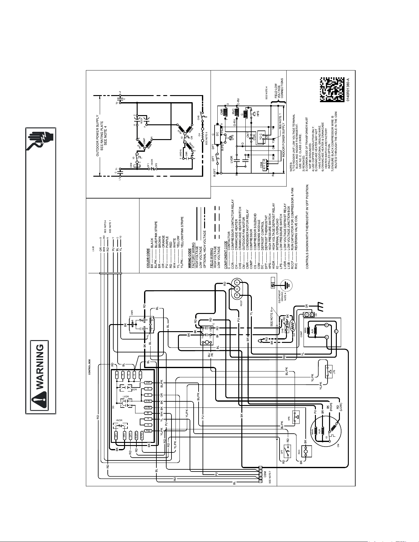
60
WIRING DIAGRAMS
HIGH VOLTAGE!
D
ISCONNECT
ALL
POWER
BEFORE
SERVICING
OR
INSTALLING
THIS
UNIT
.
M
ULTIPLE
POWER
SOURCES
MAY
BE
PRESENT
. F
AILURE
TO
DO
SO
MAY
CAUSE
PROPERTY
DAMAGE
,
PERSONAL
INJURY
OR
DEATH
.
Wiring is subject to change. Always refer to the wiring diagram on the unit for the most up-to-date wiring.
DH5SEA60
012 3
41
56
0
2
74
8
9
7
900
5
0
6
0
0
2
74
8
7
41
02
3
9
1 9
3
9
3
0
12318850 1
0
0 0 9
0
0
0 2
0 2 9
0 1 2 3
0
0 2
0
5
3
9
41
3
9
9 0 0
9 0
0 1 8 5 9 1 1 8 45 5 9 2 1 5 7 5 48 1 3 1 45 41 8
1511931 933
97548375
"#
70519 4948
4 1 5 7
1 1 57
13541874157
4 4948
4 1 5 7
1 1 57
"$%&
5
0
900
3
6
' 4 (
0
3
'
1
(
)
*
9
029
029
6
+
*
)
0
5
90
0
0
-6*-9 -6+.-7
0
9
6
-
- 9
09
9
9
009
085
-
5
95
936
0
9
0
0
3
/43285
918
8 1 5 *
8150
6 (5 1 48 1 1 9 8 45 1 1 5 7 5 9 2 48 7
1078481195921575
8007 49
(92 1
+ (0 1 2 2 1 8 4 1 5 9 7 8 1 9 2 9 2 5
8 1 5 9 1 8
*(01339018051918
)(0978077592 781 5
7 7 45 41 8 7 9 1 8 49
1(0978077592097807
7 5 9 45 0 7 9 7 0 5 1 9
48 5 7 1 3 5 41 8
3(
8970012 3919 494
9 1 5 5 9 1 5 1 48 5 0 2
8151
0
0
41
7
2 7 48
02
0
7
2 7 48
0123
0
9
02
1
9
0
8156
0
930
95
5 5
0
0
3
3
9 3 6
9
029
90
+
09
1 9
6
1
9
0
4811931 933
009
085
0
0
1
9
81 56
02
9 0 3
4 1
157
018805418
9
9
9
9
9
9
9
9
3
9
9
9
9
3 193
9
9
9
9
19
9
3
3
3
9
3
3
3
3
9
9
3
02
3
3
3
9
3
9
'4(
9
' 1 (
815*
70
3485943
91 8
1978
393
9
45
1
1 3485943
01 857051 9
012 391901857051997
097807759
097807759 450
151197821519
018892151 997
012 3919
012 39191814
019821
915018591
915592 1575
4399 450
415791597
485987191 7
1 399 450
1 15791597
1 1 5 7 8 0 5 41 8 1
9807370451919012 3919278
99487014
815*
815*
8153
3
56
6
3
8151