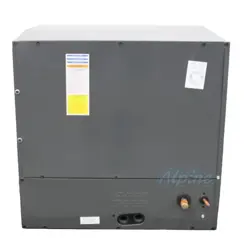
HORIZONTAL TWO-WAY COIL
INSTALLATION INSTRUCTIONS
IO-4003A
03/2022
Important Safety Instructions
The following symbols and labels are used throughout this
manual to indicate immediate or potential safety hazards.
It is the owner’s and installer’s responsibility to read and
comply with all safety information and instructions accom-
panying these symbols. Failure to heed safety information
increases the risk of personal injury, property damage, and/
or product damage.
WARNING
HIGH VOLTAGE
Disconnect all power before servicing or
installing this unit. Multiple power sources
may be present. Failure to do so may cause
property damage, personal injury or death.
Only personnel that have been trained to install, adjust,
service or repair(hereinafter, “service”) the equipment
specified in this manual should service the equipment.
The manufacturer will not be responsible for any injury
or property damage arising from improper service or
service procedures. If you service this unit, you assume
responsibility for any injury or property damage which may
result. In addition, in jurisdictions that require one or more
licenses to service the equipment specified in this manual,
only licensed personnel should service the equipment.
Improper installation, adjustment, servicing or repair of
the equipment specified in this manual, or attempting to
install, adjust, service or repair the equipment specified in
this manual without proper training may result in product
damage, property damage, personal injury or death.
WARNING
Shipping Inspection
Upon receiving the product, inspect it for damage from
shipment. Shipping damage, and subsequent investigation
is the responsibility of the carrier. Verify the model number,
specications, and accessories are correct prior to installa-
tion. The distributor or manufacturer will not accept claims
from dealers for transportation damage or installation of
incorrectly shipped units.
Handling
Use caution when transporting / carrying unit. Do not carry
unit with hooks or sharp object. The preferred method of
carrying the unit after arrival at the job site is to carry by
two-wheel hand truck from the back or sides or by hand by
carrying at the cabinet corners.
Codes & Regulations
This product is designed and manufactured to comply with
national codes. Installation in accordance with such codes
and/or prevailing local codes/regulations is the responsibil-
ity of the installer. The manufacturer assumes no respon-
sibility for equipment installed in violation of any codes or
regulations.
The United States Environmental Protection Agency
(EPA) has issued various regulations regarding the
introduction and disposal of refrigerants. Failure to
follow these regulations may harm the environment and
can lead to the imposition of substantial nes. Should
you have any questions please contact the local oce of
the EPA.
Replacement Parts
Inspect the unit to verify all required components are pres-
ent and intact. Report any missing components immedi-
ately to the manufacturer or to the distributor. Make sure
to include the full product model number and serial number
when reporting and/or obtaining service parts. Replacement
parts for this product are available through your contractor or
local distributor. For the location of your nearest distributor
consult the white business pages, the yellow page section of
the local telephone book or contact:
HOMEOWNER SUPPORT
GOODMAN MANUFACTURING COMPANY, L.P.
19001 KERMIER ROAD
WALLER, TEXAS 77484
877– 254 – 4729
Pre-Installation Instructions
Carefully read all instructions for the installation prior to
installing product. Make sure each step or procedure is
understood and any special considerations are taken into
account before starting installation. Assemble all tools,
hardware and supplies needed to complete the installation.
Some items may need to be purchased locally. Make sure
everything needed to install the product is on hand before
starting.
19001 Kermier Rd., Waller, TX 77484
© 2021-2022 Goodman Manufacturing Company, L.P.
www.goodmanmfg.com
2
System Matches
The entire system (combination of indoor and outdoor
sections) must be manufacturer approved and Air Condi-
tioning, Heating, and Refrigeration Institute (AHRI) listed.
NOTE: Installation of unmatched systems is not
permitted. Damage or repairs due to installation
of unmatched systems is not covered under the
warranty.
Application Information
Install this coil upstream (discharge air) of the furnace and
install downstream (return air) of the air handler. This coil
is bi-directional coil and can be installed in either the left or
right direction. Determine the coil direction by the side that
allows the best access.
Note: These Coils are designed for Indoor
installation only.
If the unit is located in an unconditioned area with high
ambient temperature and/or high humidity, the coil may be
subject to nuisance sweating of the casing. On these instal-
lations, a wrap of 2” berglass insulations with a vapor barri-
er is recommended
Clearances
Refrigerant lines must be routed depending on congura-
tion of unit to maintain the required 24” minimum clearance
for service. Consult all appropriate regulatory codes prior to
determining nal clearances. In installations that may lead
to physical damage (i.e. a garage) it is advised to install a
protective barrier to prevent such damage. Always install
units such that a positive slope in condensate line (1/4” per
foot) is allowed.
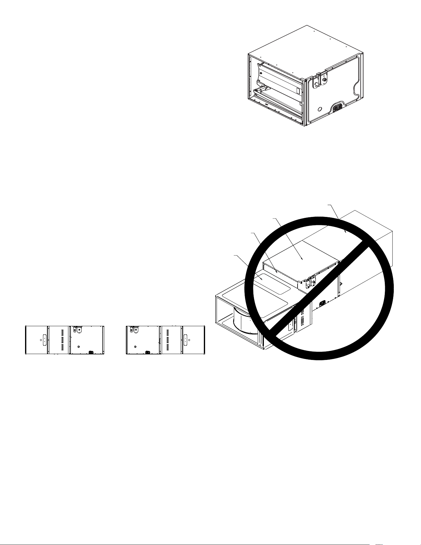
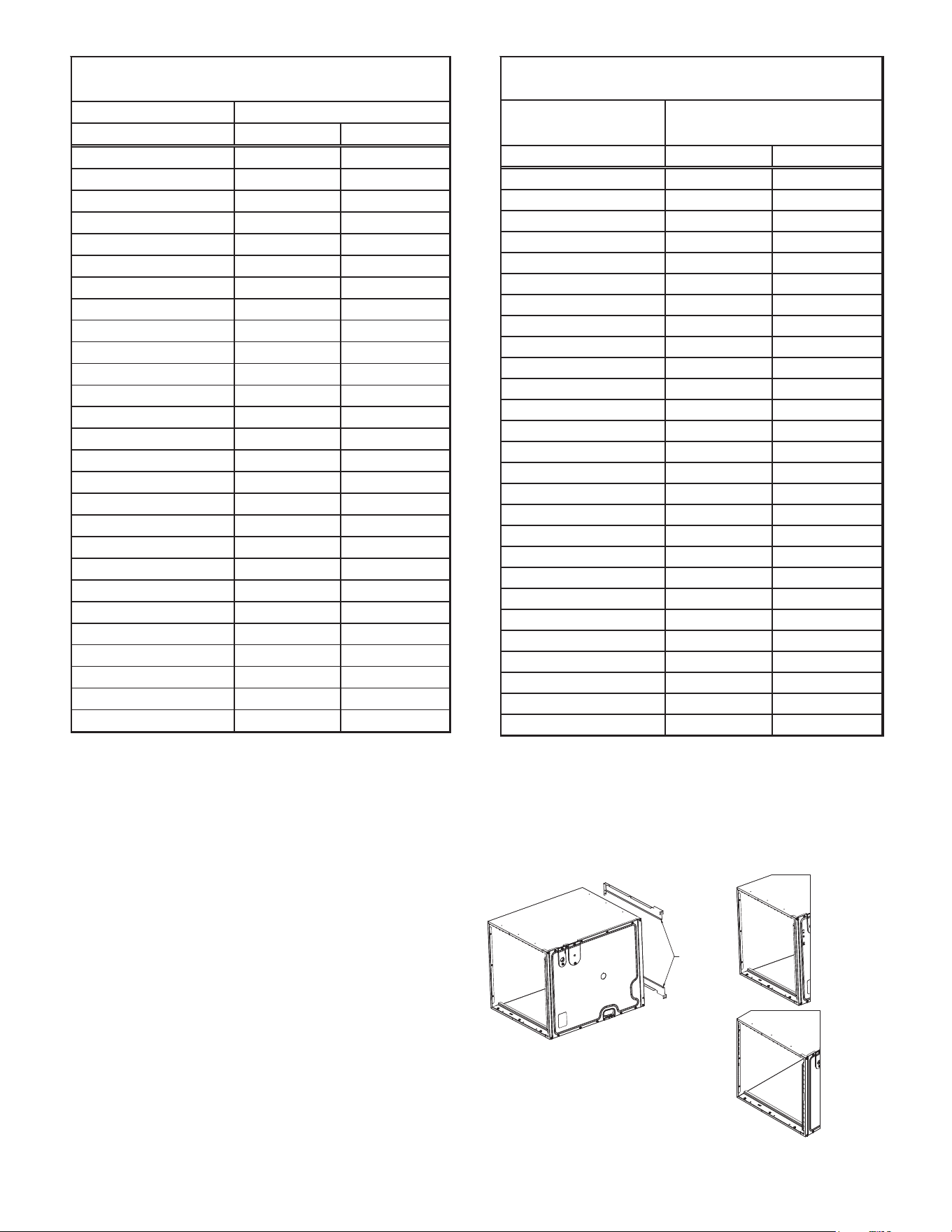
RIGHT APPLICATION
LEFT APPLICATION
Figure 1
Front View (For Right & Left Hand Application)
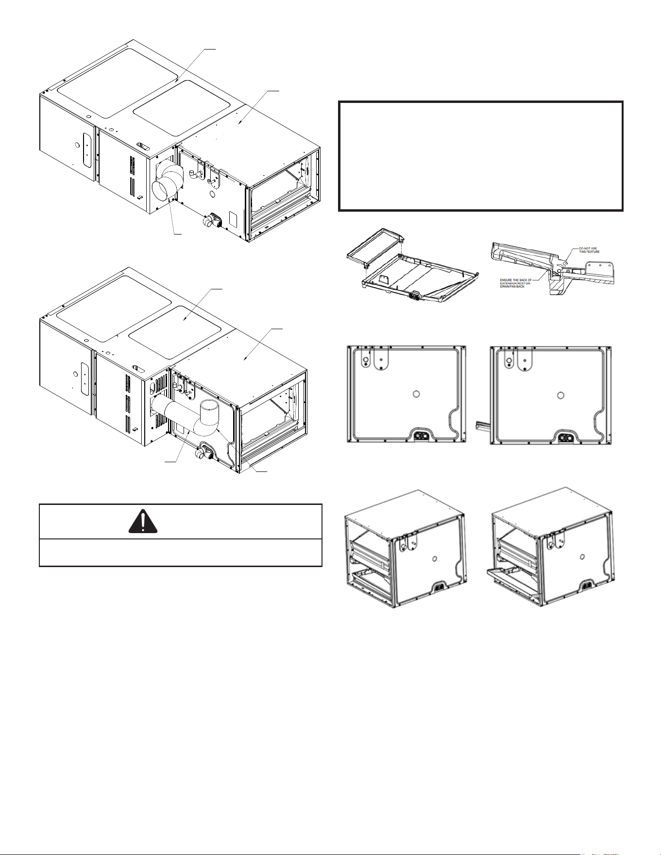
Furnace to Coil Attachment
Refer to the Furnace IO manual for further instruction.
There is no conversion required to reverse from right to left
application. Attach the duct anges to the discharge side of
the unit. If the coil and furnace combination are not similar in
depth and width, use a eld-supplied transition to center the
furnace and coil openings (see gure 5).
1. Using the hardware and brackets provided, attach the
coil to the furnace then attach the plenum to the coil
(Figure 5). Using tape or mastic seal between the coil
and furnace and the coil and plenum.
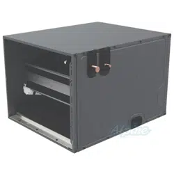
Figure 2
Actual Coil Figure
2. Please use Z-Bracket provided with units to ll the
transition gap between furnace & coil when coil is one
size larger than furnace. Additional gaps must be lled
with insulated tape or putty to prevent air leakage.
Figure 3 indicates incorrect coil/furnace attachment
method.
FURNACE
COIL
PLENUM
DUCT BOARD SHEET
METAL OR OTHER
FILLER MATERIAL
Figure 3
Incorrect Furnace, Coil and Plenum Installation
3. Optionally a transition duct can be used to attach the
coil with furnace, if z-bracket is not preferred to be
used (see gure 4E and 4F).
4. In case of CHPTA1822A coil match up with 80%
Furnace in Horizontal Right application, 90° elbow ue
vent must be used and oriented away from the cased
coil (see Figure 3A).
5. In case of other cabinet sizes match up with 80%
Furnace in Horizontal Right application, 2 qty of 90°
elbow ue vent must be used. The horizontal run
must be ≤ 75% of the vertical rise and no less than 1/4”
upward rise per foot (see Figure 3B).
3
CASED COIL
FURNACE
90° ELBOW
Figure 3A
CASED COIL
NO LESS THAN 1/4"
DRAFT UPWARD
RISE PER FOOT
FURNACE
90° ELBOW
Figure 3B
CAUTION
If drain pan extension is not locked correctly, airflow path
will be blocked and flooding may occur.
Drain Pan Extension
1. A drain pan extension is shipped with coil in the
accessory kit box (Figure 4A). This extension is to be
used only for horizontal left application used only for
higher than normal humid application. During hori-
zontal right application, this Drain Pan Extension
is not required (There are accessories recommend-
ed for horizontal right application, see page 4). This
extension will have to be locked in position for proper
application.
NOTE: To install drain pan extension, built in
duct flanges on the wrapper must be bended
in-ward or outward as needed. Remove the
drain pan extension from accessory box and
from plastic bag. Follow illustration #4B
below to install drain pan extension.
To lock extension, rotate downward away from drain
pan until snaps into position. It will act as an extension
for drain pan and must not be left lose or in the path of
airow.
Drain pan extension (black plastic part in this kit) must be installed in all horizon-
tal left application. Refer to the IO manual for complete installation instruction.
L’extension du bac de drain (pièce en plastique noir dans ce kit) doit être instal-
lée dans toutes les applications horizontales gauches. Se référer au manuel IO
pour des instructions d’installation complètes.
La extensión de la bandeja de drenaje (parte de plástica negra en este kit) debe
ser instalado en toda la aplicación horizontal izquierda. Consulte el manual de
IO para obtener las instrucciones de instalación completas.
Figure 4A
Drain pan extension is inside the accessory box
Figure 4B
Installing drain pan extension
Figure 4C and 4D
Before and After Extension has been installed
Duct Attachment
This coil’s casing is perforated for duct attachment. Howev-
er, Duct anges (Qty: 2) are shipped in a box from facto-
ry separately for the sides that have rails and perforation
can not be used. These anges are to be used over rails.
Remove center rail screw and lay over the ange on top
of rails, then attach the screw back on to secure the ange
over rails. For horizontal left application there is only one rail
(bottom) hence only one duct ange is needed and other
can be stored. For horizontal right application there are two
rail (top & bottom) and both duct anges should be used.
Duct anges can also be attached using all three screws for
the rails if additional strength is needed.
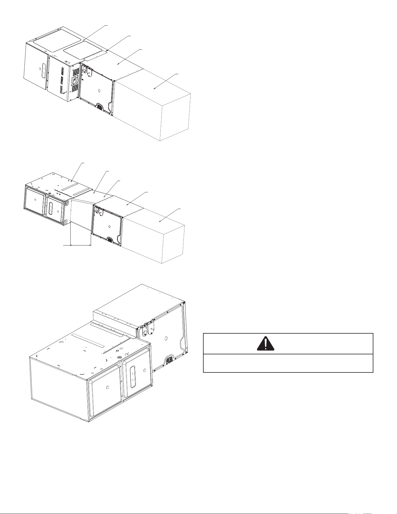
4
FURNACE
COIL
PLENUM
TOP AND BACK
BRACKET
ACCESSORY
Figure 4E
Furnace, Coil, Plenum (No Z-Bracket)
FURNACE
COIL
PLENUM
TRANSITION
MAX 10
°
ANGLE
18"
MINIMUM
Figure 4F
Furnace, Coil, Transition, Plenum (No Z-bracket)
Figure 5
Furnace, Coil and Z-Bracket Installed
Condensate Drain Piping
During cooling application, where damage from condensate
overow may occur, it is MANDATORY to install a Second-
ary drain pan under the entire coil cabinet with a separate
drain line properly sloped and terminated in an area visible
to the owner to be able to see water discharge. This second-
ary drain pan can provide extra protection to the area under
the unit should the primary drain plug up and overow. For
coils with “A” Cabinets (14” wide), use oat switch if second-
ary drain line is not installed. Refer to product nomenclature
from product specication literature to identify coil models
with “A” cabinets. As expressed in our product warranty, we
will not be liable for any damages, structural or otherwise
due to the failure to follow this installation requirement.
The coil drain pan has a primary and an optional second-
ary drain with 3/4” NPT female connections. The connectors
required can be 3/4” NPT male either PVC or metal pipe and
should be hand tightened to a torque of no more than 37
in-lbs. to prevent damage to the drain pan connection. An
insertion depth between .355 to .485 inches (3-5 turns)
should be expected at this torque. If using a copper drain
line, solder a short piece of pipe to the connector before
installing a drain tting. DO NOT over torque the 3/4” copper
connector to the plastic drain connection. Insulate PVC drain
lines/pipes with high heat resistive tape within 1” furnace
ue/vent pipe. Foil-Mastic Sealant tape is the preferred
wrapping material.
1. Ensure drain pan hole is NOT obstructed.
2. To prevent potential sweating and dripping on nished
space, it may be necessary to insulate the conden-
sate drain line located inside the building. Use Armaf-
lex® or similar material.
A Secondary Condensate Drain Connection has been
provided for areas where the building codes require it. Pitch
the drain line 1/4” per foot to provide free drainage. Insulate
drain lines (primary and secondary) located inside the build-
ing to prevent sweating. Install a condensate trap in the
primary drain line to ensure proper drainage. If the second-
ary line is required, run the line separately from the primary
drain and end it where it can be easily seen.
NOTE: Water coming from this line means the coil
primary drain is plugged and needs clearing.
CAUTION
If secondary drain is not installed, the secondary access
must be plugged.
NOTE: Trapped lines are required by many local codes. In
the absence of any prevailing local codes, please refer to
the requirements listed in the Uniform Mechanical Building
Code. A drain trap in a draw-through application prevents
air from being drawn back through the drain line during fan
operation thus preventing condensate from draining, and
if connected to a sewer line to prevent sewer gases from
being drawn into the airstream during blower operation. In a
blow-through application the drain trap prevents conditioned
air from escaping.
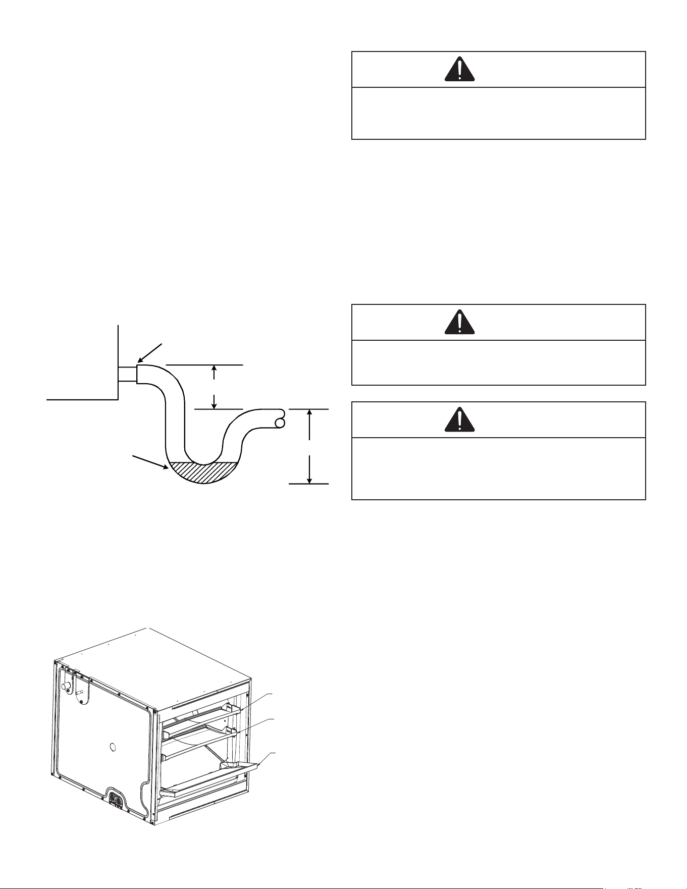
The installation must include a “P” style trap that is located
as close as is practical to the evaporator coil. See Figure 6
for details of a typical condensate line “P” trap.
5
NOTE: Units operating in high static pressure
applications may require a deeper field construct-
ed “P” style trap than is shown in Figure 6 to
allow proper drainage and prevent condensate
overflow.
Use of a condensate removal pump is permitted when
necessary. This condensate pump should have provisions
for shutting o the control voltage should a blocked drain
occur. A trap must be installed between the unit and the
condensate pump.
IMPORTANT NOTE: The evaporator coil is fabri-
cated with oils that may dissolve Styrofoam and
certain types of plastics. Therefore, a removal
pump or float switch must not contain any of
these materials.
TIP: Priming the “P” trap may avoid improper draining at the
initial installation and at the beginning of the cooling season.
Cased Coil
3" MIN.
POSITIVE LIQUID SEAL
REQUIRED AT TRAP
Drain
Connection
2" MIN.
Figure 6
Condensate Drain Trap
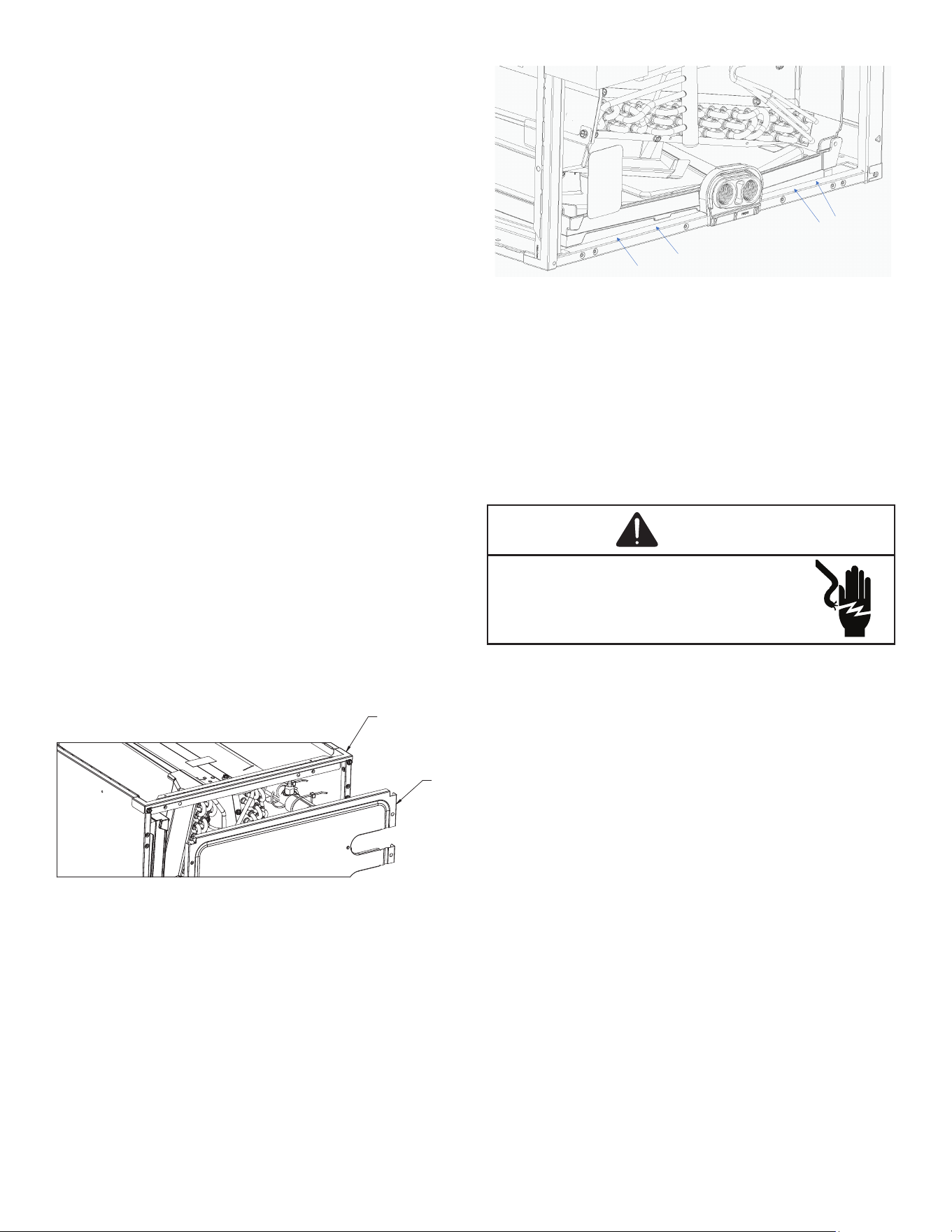
Horizontal Right Coil Accessories
In application where the Horizontal coil is installed in the
right position, and the return air environment see humidity
level above 65% relative humidity coupled with total external
static levels above 0.5” e.s.p, a condensate management
accessory kit is available for eld application. Sold separate-
ly, please refer to kit installation instruction IOG-7008.
SMALL CONDENSATE
COLLECTOR
SPLASH GUARD
LARGE CONDENSATE
COLLECTOR
Figure 7
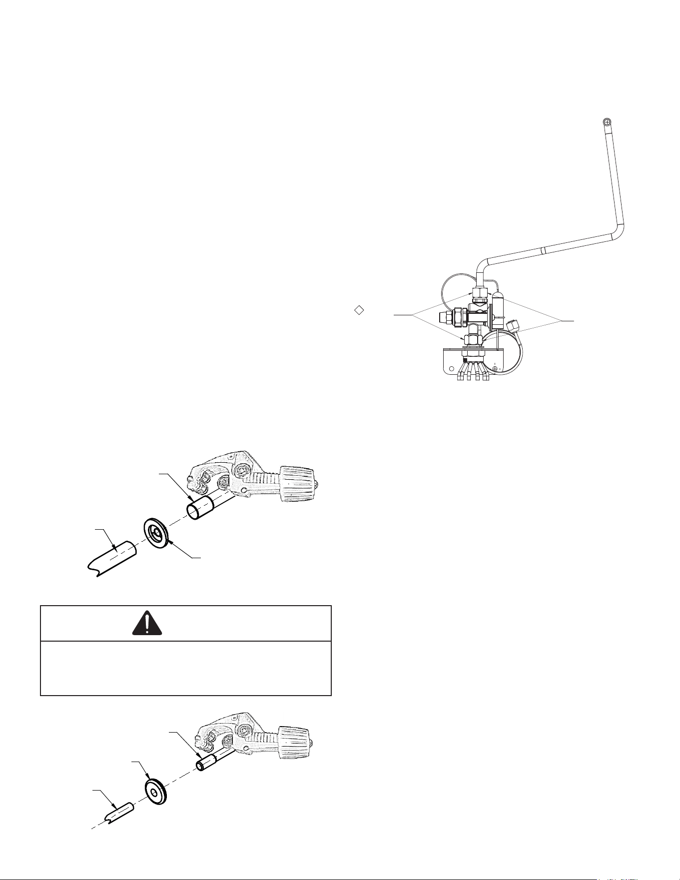
Refrigerant Lines
WARNING
A quenching cloth is strongly recommended to prevent
scorching or marring of the equipment finish when brazing
close to the painted surfaces. Use brazing alloy of 5%
minimum silver content.
All cut ends are to be round, burr free, and cleaned. Any
other condition increases the chance of a refrigerant leak.
Use a pipe cutter to remove the closed end of the spun
closed suction line.
To avoid overheating after brazing, quench all welded joints
with water or a wet rag.
For the correct tubing size, follow the specication for the
condenser/heat pump
CAUTION
The coil is shipped under pressure with a R-410A gas mixture.
Use appropriate service tools and follow these instructions
to prevent injury.
CAUTION
Applying too much heat to any tube can melt the tube.
Torch heat required to braze tubes of various sizes must be
proportional to the size of the tube. Service personnel must
use the appropriate heat level for the size of the tube being
brazed.
NOTE: Tubes of smaller size require less heat
to bring the tube to brazing temperature before
adding brazing alloy. The use of a heat shield
when brazing is recommended to avoid burning the
serial plate or the finish on the unit.
Refrigerant tubing must be routed to allow adequate access
for servicing and maintenance of the unit. Do not handle
coil assembly with manifold or owrator tubes. Doing so
may result in damage to the tubing joints. Always use clean
gloves for handling coil assemblies.
Tubing Size/Length
For the correct tubing size, follow the specication for the
condenser/heat pump. Give special consideration to mini-
mizing the length of refrigerant tubing when installing coils.
Refer to Remote Cooling/Heat Pump Technical Publication
TP-107* Long Line Set Application R-410A for guidelines for
line lengths over 80’. Leave a minimum 3” straight in line set
from braze joints before any bends.
6
Tubing Preparation
All cut ends are to be round, burr free, and cleaned. Any
other condition increases the chance of a refrigerant leak.
Use a pipe cutter to remove the closed end of the spun
closed suction line.
NOTE: To prevent possible damage to the tubing
joints, do not handle coil assembly with manifold
or flowrator tubes. Always use clean gloves when
handling coil assemblies.
Brazing
Braze joints should be made only with the connections
provided external to the cabinet. Do not alter the cabinet nor
braze inside the cabinet. To avoid overheating after brazing,
quench all brazed joints with water or a wet rag.
Tubing Connections for TXV Version
TXV models come with factory installed adjustable TXV
with the bulb permanently located on the suction tube.
1. Remove coil access panel and rubber grommets.
2. Remove access valve tting cap and depress the
valve stem in access tting to release pressure. No
pressure indicates possible leak.
3. Reinstall the Coil Access Panel & rubber grommets.
4. Remove the spin closure on both the liquid and
suction tubes using a tubing cutter. DO NOT USE
A CUTTING METHOD THAT WOULD RESULT IN
THE GENERATION OF COPPER SHAVINGS OR
COPPER DUST.
SUCTION
LINE SET
SUCTION
TUBE
RUBBER
GROMMET
Figure 8.1
CAUTION
Excessive torque can cause TXV retaining ring to weaken &
create leak and will become difficult to re-install TXV. Use
the proper torque (180-240in. ilbs) settings when tightening
the TXV or hand tighten plus 1/2 turn.
LIQUID
LINE SET
LIQUID
LINE
RUBBER
GROMMET
Figure 8.2
5. Insert liquid line set into liquid tube expansion and
slide grommet about 18” away from braze joint.
6. Insert suction line set into suction tube expansion and
slide insulation and grommet about 18” away from
braze joint.
7. Braze suction and liquid line joints.
TORQUE
180-240 IN-LBS
CC
ENSURE THAT SEAL
WASHERS STAY
IN POSITION
Figure 9
9.5 Thermal Expansion Valve System Adjustment
Run the system at Cooling for 10 minutes until refrigerant
pressures stabilize. Use the following guidelines and meth-
ods to check unit operation and ensure that the refrigerant
charge is within limits. Charge the unit on low stage.
Purge gauge lines. Connect service gauge manifold to
base-valve service ports.
Temporarily install a thermometer on the liquid line at the
liquid line service valve and 4-6” from the compressor on
the suction line. Ensure the thermometer makes adequate
contact and is insulated for best possible readings. Use
liquid line temperature to determine subcooling and vapor
temperature to determine superheat.
8. Check subcooling and superheat. Systems with TXV
application should have a subcooling of 7 to 9ºF and
superheat of 7 to 9ºF.
a. If subcooling and superheat are low, adjust TXV
to 7 to 9ºF superheat, then check subcooling.
NOTE: To adjust superheat, turn the valve stem
clockwise to increase and counter clockwise to
decrease.
b. If subcooling is low and superheat is high, add
charge to raise subcooling to 7 to 9ºF then check
superheat.
c. If subcooling and superheat are high, adjust TXV
valve to 7 to 9ºF superheat, then check subcooling.
7
SUCTION PRESSURE
PSIG R-22 R-410A
50 26 1
52 28 3
54 29 4
56 31 6
58 32 7
60 34 8
62 35 10
64 37 11
66 38 13
68 40 14
70 41 15
72 42 16
74 44 17
76 45 19
78 46 20
80 48 21
85 50 24
90 53 26
95 56 29
100 59 31
110 64 36
120 69 41
130 73 45
140 78 49
150 83 53
160 86 56
170 90 60
SATURATED SUCTION PRESSURE
TEMPERATURE CHART
SATURATED SUCTION
d. If subcooling is high and superheat is low, adjust
TXV valve to 7 to 9ºF superheat and remove
charge to lower the subcooling to 7 to 9ºF.
NOTE: Do NOT adjust the charge based on suction
pressure unless there is a gross undercharge.
4. Disconnect manifold set, installation is complete.
NOTE: Check the Schrader ports for leaks and
tighten valve cores if necessary. Install caps
finger-tight.
SUBCOOL FORMULA = SAT. LIQUID LINE TEMP. - LIQUID
LINE TEMP.
SUPERHEAT FORMULA = SUCT. LINE TEMP. - SAT. SUCT.
TEMP.
LIQUID PRESSURE
PSIG R-22 R-410A
200 101 70
210 105 73
220 108 76
225 110 78
235 113 80
245 116 83
255 119 85
265 121 88
275 124 90
285 127 92
295 130 95
305 133 97
325 137 101
355 144 108
375 148 112
405 155 118
415 157 119
425 n/a 121
435 n/a 123
445 n/a 125
475 n/a 130
500 n/a 134
525 n/a 138
550 n/a 142
575 n/a 145
600 n/a 149
625 n/a 152
SATURATED LIQUID PRESSURE
TEMPERATURE CH ART
SATURATED LIQUID
TEMPERATURE ºF
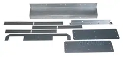
Filler Plates
Filler plates are supplied on all 17.5, 21, & 24.5 inch chassis
to be used for adapting the unit to a furnace one size small-
er. If the plenum and furnace openings are the same size,
the ller plates must be removed. See Figure 10.
DETAIL TOP FLANGE VIEW
DETAIL UNFOLDED VIEW
BLOCK OFF PLATE
Figure 10
Block-o Plates & Duct Flange Detail
8
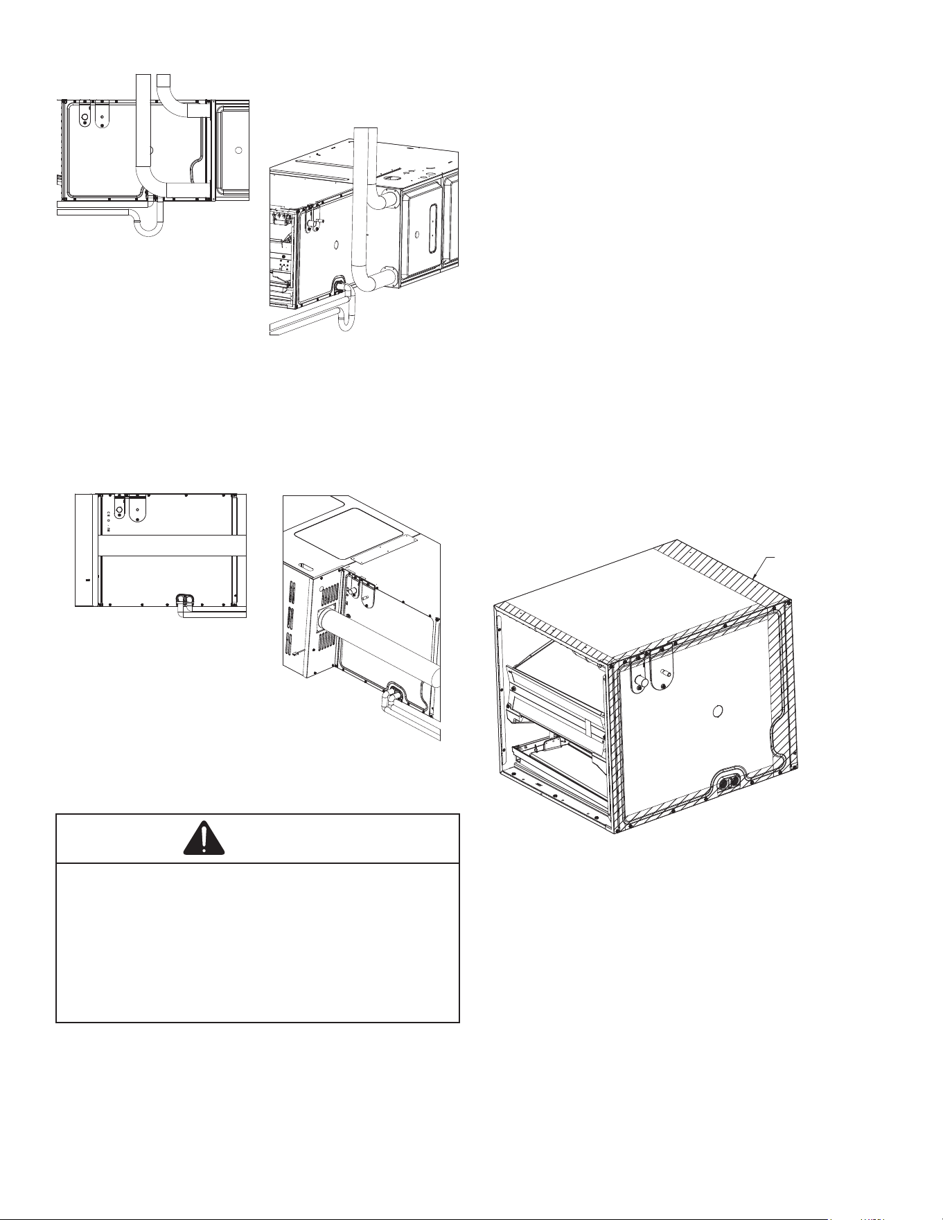
Drain Line and Flue Vent Piping
Figure 11
90% Flue Vent & Drain Port
A minimum of 2.0” distance from the top of the furnace and
the bottom of the coil pan is required.
NOTE: The coil must be installed with the line set
and drain openings to the front of the furnace.
Figure 12
80% Flue Vent & Drain Port
Plastic Drain Pan Application
WARNING
Do not use the coil pan shipped with the unit on oil furnaces
or any application where the temperature of the drain
pan may exceed 300°F. A high temperature drain pan such as
kits HTP-A, -B, -C, and -D for normal cabinet widths of 14,
17.5, 21 and 24.5 inches, respectively, should be used for
applications where the temperature exceeds 300°F and below
450°F. A field fabricated metal drain pan can also be used for
applications where temperature exceeds 300°F. Failure to
follow this warning may result in property damage and/pr
personal injury.
NOTE: Water coming from the secondary line
means the coil primary drain is plugged and needs
immediate attention.
Install a trap in the drain line below the bottom of the drain
pan. If using a copper drain line, solder a short piece of pipe,
minimum 6” length, to the connector before installing a drain
tting.
DO NOT over torque the 3/4” copper connector to the plastic
drain connection. Using a wet rag or heatsink material on
the short piece to protect the plastic drain pan, complete the
drain line installation. Use Figure 6 as a template for typical
drain pipe routing. This gure shows how to avoid interfer-
ence with vent piping.
Return Ductwork
DO NOT TERMINATE THE RETURN DUCTWORK IN AN
AREA THAT CAN INTRODUCE TOXIC OR OBJECTION-
ABLE FUMES/ODORS INTO THE DUCTWORK.
Sealing Along The Panel Gap
IMPORTANT NOTE: To prevent cabinet sweating and
airflow leak, apply field provided insulation tape
along all joining surfaces between the coil, gas
furnace, duct work and panels. See Figure 13.
APPLY INSULATION TAPE
Figure 13
Panel Gap Sealing
9
Aluminum Indoor Coil Cleaning
(Qualied Servicer Only)
This unit is equipped with an aluminum tube evaporator coil.
The safest way to clean the evaporator coil is to simply ush
the coil with water. This cleaning practice remains as the
recommended cleaning method for both copper tube and
aluminum tube residential cooling coils.
An alternate cleaning method is to use one of the products
listed in the technical publication TP-109 (shipped in the
literature bag with the unit) to clean the coils. The clean-
ers listed are the only agents deemed safe and approved for
use to clean round tube aluminum coils. TP-109 is available
on the web site in Partner Link > Service Toolkit.
NOTE: Ensure coils are rinsed well after use of
any chemical cleaners.
Top anges can be bent for ease in installation to
the duct anges.
Removing Coil from Cabinet
In an event of removing taller coils from cabinet to service
or replace; remove access panel, remove top tie rail to allow
the coils to slide out of the cabinet.
After service or replacement slide the coil back in the cabi-
net and secure the top tie rail and re-install access panel.
See Figure 14.
If the coil is hitting the bottom wrapper ange of the cabi-
net, pinch the mental ange (wrapper ange) closed, so the
drain pan can slide in and out on the rail. See Figure 15 for
an example of the ange that may need to be pinched shut.
TOP TIE
PANEL
Figure 14
Wrapperflange
Wrapperflange
Figure 15
Wrapper Flange
Clean Comfort brand UV coil puriers also can be purchased
from distributor. Maximum UV lamp diameter to be used per
delta plate knockout design is 1.375” to reduce the possibil-
ity of air leak.
Refer to UV coil puriers product specication and installa-
tion manual for additional details.
Start-Up Procedure
WARNING
HIGH VOLTAGE
Disconnect all power before servicing or
installing this unit. Multiple power sources
may be present. Failure to do so may cause
property damage, personal injury or death.
• Prior to start-up, ensure that all electrical wires are
properly sized and all connections are properly
tightened.
• All panels must be in place and secured. For air tight
application, gasket must be positioned at prescribed
locations to achieve 1.4% leakage.
• Tubing must be leak free.
• Condensate line must be trapped and pitched to allow
for drainage.
• Low voltage wiring is properly connected.
• Auxiliary drain is installed when necessary and
pitched to allow for drainage.
• Unit is protected from vehicular or other physical
damage.
• Return air is not obtained from, nor are there any
return air duct joints that are unsealed in, areas where
there may be objectionable odors, ammable vapors
or products of combustion such as carbon monoxide
(CO), which may cause serious personal injury or
death.
10
Air Handler / Coil
ELECTRICAL
Line Voltage (Measure L1 and L2 Voltage) L1 - L2
Secondary Voltage (Measure Transformer Output Voltage) R - C
Blower Amps
Heat Strip 1 - Amps
Heat Strip 2 - Amps
BLOWER EXTERNAL STATIC PRESSURE
Return Air Static Pressure IN. W.C.
Supply Air Static Pressure IN. W.C.
Total External Static Pressure (Ignoring +/- from the reading above, add total here) IN. W.C.
TEMPERATURES
Return Air Temperature (Dry bulb / Wet bulb) DB °F WB °F
DB °F WB °F
Heating Supply Air Temperature DB °F
Temperature Rise DB °F
Delta T (Difference between Supply and Return Temperatures) DB °F
Air Handler / Coil - (Inverter Matched)
INVERTER AH / COIL ONLY
Check EEV and EEV wiring is secure (no adjustment required)
Additional Checks
Check wire routings for any rubbing
Check product for proper draining
Check screw tightness on blower wheel
Check factory wiring and wire connections
Check product for proper clearances as noted by installtion instructions
°F to °C formula: (°F - 32) divided by 1.8 = °C °C to °F formula: (°C multiplied by 1.8) + 32 = °F
Model Number
Serial Number
Cooling Supply Air Temperature (Dry bulb / Wet bulb)
START-UP CHECKLIST

11
PAGE LEFT INTENTIONALLY BLANK
12
CUSTOMER FEEDBACK
We are very interested in all product comments.
Please ll out the feedback form on one of the following links:
Daikin Products: (https://daikincomfort.com/contact-us)
Goodman
®
Brand Products: (http://www.goodmanmfg.com/about/contact-us).
Amana
®
Brand Products: (http://www.amana-hac.com/about-us/contact-us).
You can also scan the QR code on the right for the product brand you
purchased to be directed to the feedback page.
DAIKIN
AMANA
®
BRAND
GOODMAN
®
BRAND
PRODUCT REGISTRATION
Thank you for your recent purchase. Though not required to get the
protection of the standard warranty, registering your product is a relatively
short process, and entitles you to additional warranty protection, except that
failure by California and Quebec residents to register their product does not
diminish their warranty rights.
DAIKIN
AMANA
®
BRAND
GOODMAN
®
BRAND
For Product Registration, please register as follows:
Daikin Products: (https://daikincomfort.com/owner-support/product-registration).
Goodman® Brand products: (https://www.goodmanmfg.com/product-registration).
Amana® Brand products: (http://www.amana-hac.com/product-registration).
You can also scan the QR code on the right for the product brand you purchased
to be directed to the Product Registration page.
NOTE: SPECIFICATIONS AND PERFORMANCE DATA LISTED HEREIN ARE SUBJECT TO CHANGE WITHOUT NOTICE
19001 Kermier Rd, Waller, TX 77484
© 2021-2022 Goodman Manufacturing Company, L.P.
www.goodmanmfg.com
is a registered trademark of Maytag Corporation or its related companies and is used
under license. All rights reserved.