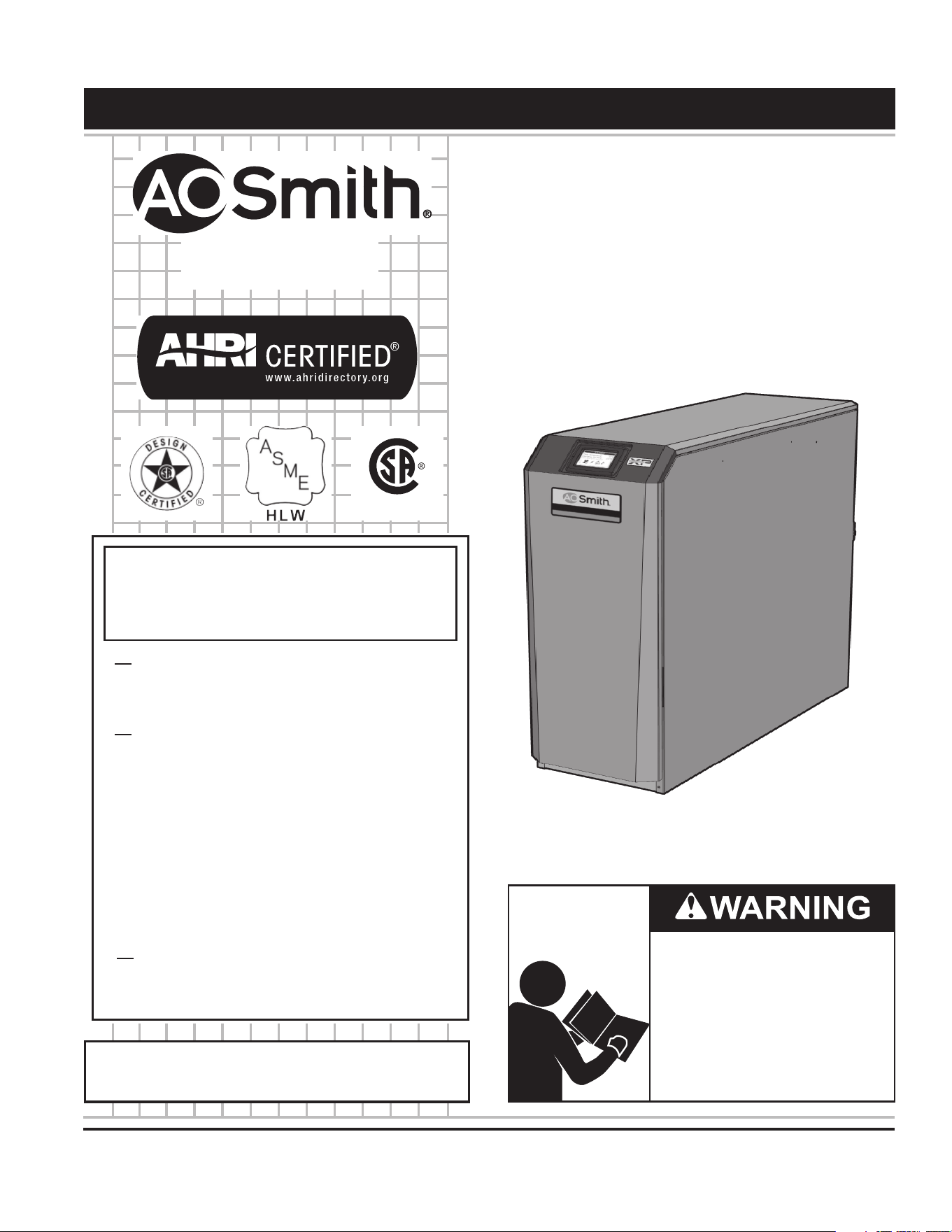
COMMERCIAL GAS WATER HEATERS
Instruction Manual
PRINTED 0419 100280461_2000538785_Rev F
PLACE THESE INSTRUCTIONS ADJACENT TO HEATER AND NOTIFY OWNER TO KEEP FOR FUTURE REFERENCE.
Thank you for buying this energy effi cient water heater.
We appreciate your confi dence in our products.
Read and understand this instruction
manual and the safety messages
herein before installing, operating or
servicing this water heater.
Failure to follow these instructions and
safety messages could result in death
or serious injury.
This manual must remain with the
water heater.
MODELS XWH 150 - 800
INSTALLATION - OPERATION - SERVICE
- MAINTENANCE - LIMITED WARRANTY
WARNING: If the information in these
instructions is not followed exactly, a fire
or explosion may result causing property
damage, personal injury or death.
Do not store or use gasoline or other
flammable vapors and liquids in the
vicinity of this or any other appliance.
WHAT TO DO IF YOU SMELL GAS:
•
Do not try to light any appliance.
•
Do not touch any electrical switch; do
not use any phone in your building.
•
Immediately call your gas supplier
from a neighbor’s phone. Follow the
gas supplier’s instructions.
•
If you cannot reach your gas supplier,
call the fire department.
Installation and service must be
performed by a qualified installer,
service agency or the gas supplier.
500 Tennessee Waltz Parkway
Ashland City, TN 37015
www.hotwater.com
LOW LEAD CONTENT

2
Propane (LP) Gas ............................................................................ 46
Field Wiring ...................................................................................... 49
Condensate Disposal ...................................................................... 52
START UP ............................................................................................ 53
Operating Instructions For Models 150 - 285 .................................. 55
Operating Instructions For Models 400 - 800 .................................. 56
CONTROL SYSTEM OPERATION ...................................................... 57
General ............................................................................................ 57
Sequence Of Operation ................................................................... 59
User Interface Module (UIM)/ Touch Screen Display....................... 60
Status Icons ..................................................................................... 61
Operating States .............................................................................. 62
Control System Menus .................................................................... 62
MAINTENANCE ................................................................................... 63
Maintenance Schedules .................................................................. 63
Maintenance .................................................................................... 64
WIRING DIAGRAMS ............................................................................ 67
NOTES ................................................................................................. 69
LIMITED WARRANTY .......................................................................... 71
TABLE OF CONTENTS
SAFE INSTALLATION, USE AND SERVICE.......................................... 3
APPROVALS .......................................................................................... 3
GENERAL SAFETY INFORMATION ...................................................... 4
Precautions ........................................................................................ 4
Grounding Instructions ...................................................................... 4
Hydrogen Gas Flammable ................................................................. 4
INTRODUCTION .................................................................................... 6
Abbreviations Used ........................................................................... 6
Qualifi cations ..................................................................................... 6
Preparing For The Installation ........................................................... 6
FEATURES AND COMPONENTS ......................................................... 7
INSTALLATION CONSIDERATIONS ................................................... 10
Rough In Dimensions ...................................................................... 10
Ratings .............................................................................................11
Determine Water Heater Location ....................................................11
Closet And Alcove Installations ........................................................ 12
Corrosive Materials And Contamination Sources ............................ 14
When Using An Existing Vent System To Install A New Water Heater
......................................................................................................... 14
When Removing A Water Heater From Existing Common Vent
System ............................................................................................. 14
Removing A Water Heater From Wood Pallet ................................. 15
Gas Conversions ............................................................................. 15
Leveling The Water Heater .............................................................. 16
VENTING INSTALLATION ................................................................... 17
Direct Venting Options - Sidewall Vent ............................................ 17
Install Vent And Combustion Air Piping ........................................... 18
Air Inatke/ Vent Connections ........................................................... 18
Sizing ............................................................................................... 19
Minimum/ Maximum Allowable Combustion Air And Vent Piping
Lengths Are As Follows ................................................................... 19
Air Inlet Pipe Materials ..................................................................... 19
Vent, Air Piping And Termination...................................................... 20
PVC/ CPVC ..................................................................................... 20
Polypropylene .................................................................................. 21
Stainless Steel Vent ......................................................................... 23
Vent/ Air Termination - Sidewall ....................................................... 24
Vent/ Air Termination - Sidewall ....................................................... 25
Sidewall Direct Venting .................................................................... 29
Multiple Vent/ Air Terminations......................................................... 30
Sidewall Termination – Optional Concentric Vent: Models 150 - 600
......................................................................................................... 31
Multiventing Sidewall Terminations .................................................. 33
Vertical Direct Venting ..................................................................... 34
Vertical Termination - Optional Concentric Vent: Models 150 - 600 36
Alternate Vertical Concentric Venting .............................................. 38
WATER HEATER INSTALLATION ........................................................ 39
System Piping .................................................................................. 39
Flow Switch And Temperature & Pressure Relief Valve (T & P Relief
Valve) Installation............................................................................. 39
Piping Components ......................................................................... 40
Gas Connections ............................................................................. 45
Natural Gas ..................................................................................... 46
3
SAFE INSTALLATION, USE AND SERVICE
The proper installation, use and servicing of this water heater is extremely important to your safety and the safety of others.
Many safety-related messages and instructions have been provided in this manual and on your own water heater to warn you and
others of a potential injury hazard. Read and obey all safety messages and instructions throughout this manual. It is very important
that the meaning of each safety message is understood by you and others who install, use, or service this water heater.
All safety messages will generally tell you about the type of hazard, what can happen if you do not follow the safety message, and
how to avoid the risk of injury.
DANGER
WARNING
CAUTION
CAUTION
DANGER indicates an imminently
hazardous situation which, if not avoided,
will result in injury or death.
This is the safety alert symbol. It is used to alert you to
potential personal injury hazards. Obey all safety
messages that follow this symbol to avoid possible
injury or death.
WARNING indicates a potentially hazardous
situation which, if not avoided, could result
in injury or death.
CAUTION indicates a potentially hazardous
situation which, if not avoided, could result in
minor or moderate injury.
CAUTION used without the safety alert
symbol indicates a potentially hazardous
situation which, if not avoided, could result in
property damage.
APPROVALS
LOW LEAD CONTENT
4
PRECAUTIONS
DO NOT USE THIS WATER HEATER IF ANY PART HAS
BEEN EXPOSED TO FLOODING OR WATER DAMAGE.
Immediately call a qualifi ed service agency to inspect the
water heater and to make a determination on what steps
should be taken next.
If the unit is exposed to the following, do not operate heater
until all corrective steps have been made by a qualified
service agency.
1. External fi re.
2. Damage.
3. Firing without water.
GROUNDING INSTRUCTIONS
This water heater must be grounded in accordance with the
National Electrical Code and/or local codes. These must be
followed in all cases. Failure to ground this water heater
properly may also cause erratic control system operation.
This water heater must be connected to a grounded metal,
permanent wiring system; or an equipment grounding
conductor must be run with the circuit conductors and
connected to the equipment grounding terminal or lead on
the water heater.
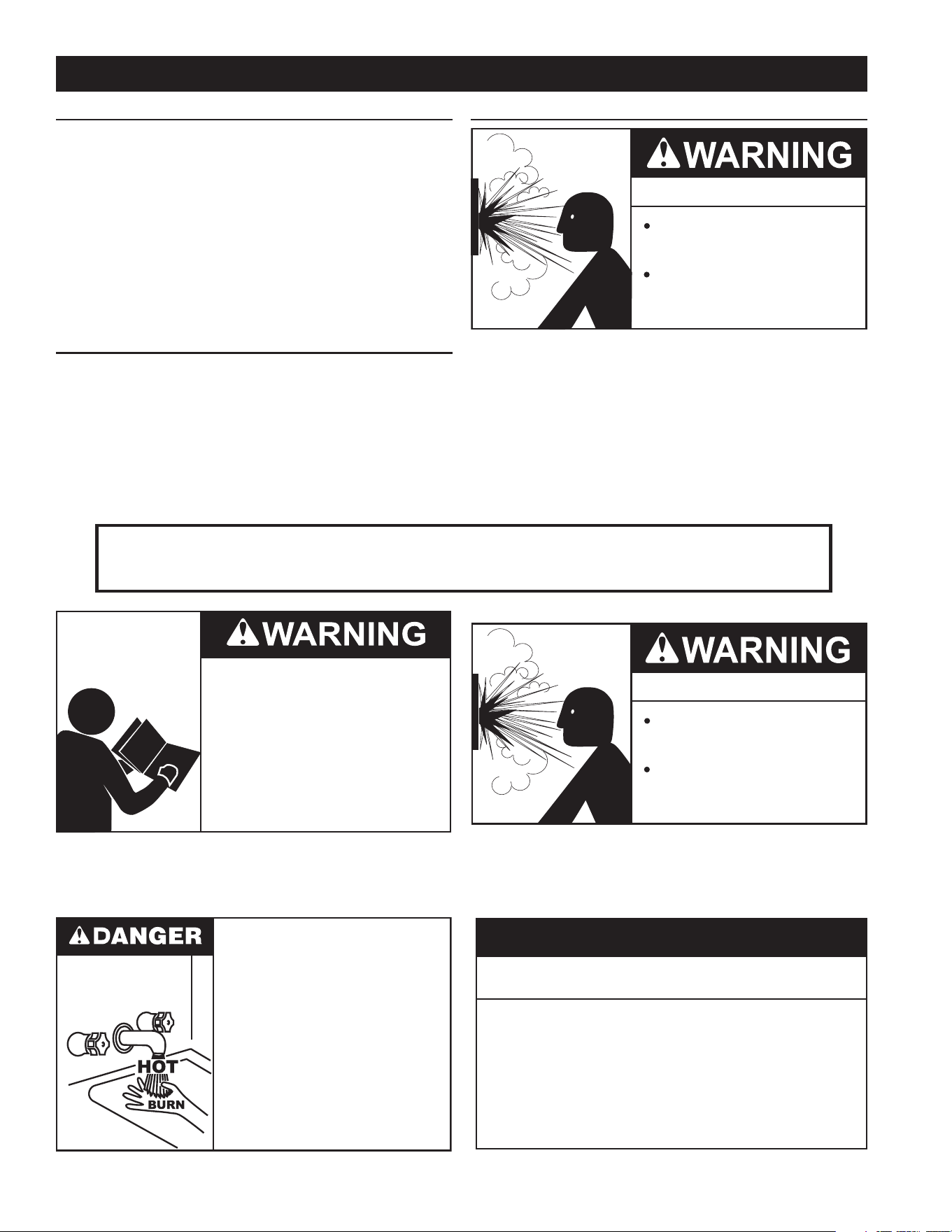
HYDROGEN GAS FLAMMABLE
Explosion Hazard
Flammable hydrogen gases
may be present.
Keep all ignition sources away
from faucet when turning on
hot water.
Hydrogen gas can be produced in a hot water system served
by this water heater that has not been used for a long period of
time (generally two weeks or more). Hydrogen gas is extremely
fl ammable. To reduce the risk of injury under these conditions, it is
recommended that a hot water faucet served by this water heater
be opened for several minutes before using any electrical appliance
connected to the hot water system. If hydrogen is present there will
probably be an unusual sound such as air escaping through the pipe
as the water begins to fl ow. THERE SHOULD BE NO SMOKING
OR OPEN FLAME NEAR THE FAUCET AT THE TIME IT IS OPEN.
GENERAL SAFETY INFORMATION
Read and understand this instruction
manual and the safety messages
herein before installing, operating or
servicing this water heater.
Failure to follow these instructions and
safety messages could result in death
or serious injury.
This manual must remain with the
water heater.
Water temperature over 125°F (52°C)
can cause severe burns instantly
resulting in severe injury or death.
Children, the elderly and the
physically or mentally disabled are at
highest risk for scald injury.
Feel water before bathing or
showering.
Temperature limiting devices such as
mixing valves must be installed
when required by codes and to
ensure safe temperatures at fixtures.
Explosion Hazard
Overheated water can cause
water tank explosion.
Properly sized temperature and
pressure relief valve must be
installed in the opening provided.
Verify the power to the water heater is turned off before performing any service procedures.
The Enable /Disable switch on front panel disables the 24 volt gas valve. Electrical supply
must be turned off at circuit breaker serving water heater.
Improper installation, use and service may result
in property damage.
Do not operate water heater if exposed to flooding or
water damage.
•
Install in location with drainage.
•
Properly sized thermal expansion tanks are required on all
closed water systems.
•
Refer to this manual for installation and service.
CAUTION
5
GENERAL SAFETY INFORMATION
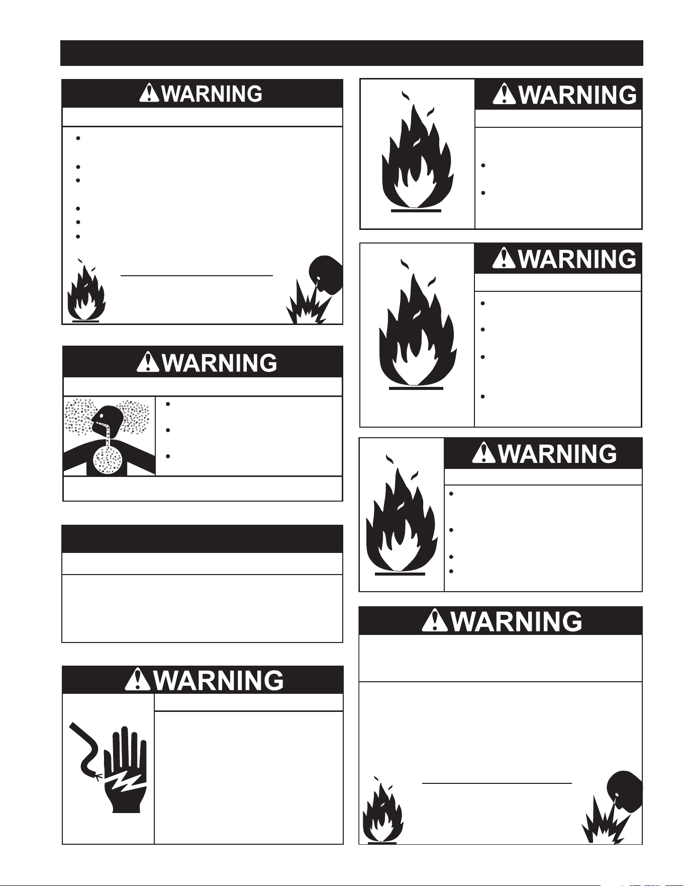
Fire Hazard
Do not install water heater on
carpeted floor.
Do not operate water heater if
exposed to flooding or water
damage.
For continued protection against
risk of fire:
Fire or Explosion Hazard
Read instruction manual before
installing, using or servicing
water heater.
Avoid all ignition sources if you smell gas.
Do not store or use gasoline or other flammable vapors and
liquids in the vicinity of this or any other appliance.
Use only the gas shown on the water heater rating label.
Keep ignition sources away from faucets after extended
periods of non-use.
Maintain required clearances to combustibles.
Do not expose water heater controls to excessive gas
pressure.
Do not obstruct water heater air intake
with insulating blanket.
Gas and carbon monoxide detectors
are available.
Install water heater in accordance with
the instruction manual.
Breathing carbon monoxide can cause brain damage or
death. Always read and understand instruction manual.
Breathing Hazard - Carbon Monoxide Gas
Property Damage Hazard
All water heaters eventually leak.
•
Do not install without adequate drainage.
•
CAUTION
Fire and Explosion Hazard
Leak test gas connections before
placing water heater in operation.
Disconnect gas piping at main
gas shutoff valve before leak
testing heater.
Install sediment trap in
accordance with NFPA 54 or
CAN/CSA B149.1.
Use joint compound or Teflon tape
compatible with propane gas.
Fire and Explosion Hazard
Turn off gas lines during installation.
Contact a qualified installer or service
agency for installation and service.
Excessive gas pressure to gas valve can
cause serious injury or death.
Do not use water heater with any gas
other than the gas shown on the rating
label.
Turn off power at the branch circuit
breaker serving the water heater
before performing any service.
Electrical Shock Hazard
•
Label all wires prior to disconnecting
when performing service. Wiring errors
can cause improper and dangerous
operation.
•
Verify proper operation after servicing.
•
Failure to follow these instructions can
result in personal injury or death.
•
Jumping out control circuits or components can
result in property damage, personal injury or death.
Service should only be performed by a qualified service
technician using proper test equipment.
•
Altering the water heater controls and/or wiring in any way
could result in permanent damage to the controls or water
heater and is not covered under the limited warranty.
•
Any bypass or alteration of the water
heater controls and/or wiring will result
in voiding the appliance warranty.

6
Thank You for purchasing this water heater. Properly installed
and maintained, it should give you years of trouble free service.
ABBREVIATIONS USED
Abbreviations found in this Instruction Manual include :
• ANSI - American National Standards Institute
• ASME - American Society of Mechanical Engineers
• AHRI - Air Conditioning, Heating and Refrigeration Institute
• NEC - National Electrical Code
• NFPA - National Fire Protection Association
• UL - Underwriters Laboratory
QUALIFICATIONS
QUALIFIED INSTALLER OR SERVICE AGENCY
Installation and service of this water heater requires ability
equivalent to that of a Qualifi ed Agency (as defi ned by ANSI
below) in the fi eld involved. Installation skills such as plumbing,
air supply, venting, gas supply and electrical supply are required
in addition to electrical testing skills when performing service.
ANSI Z223.1 2006 Sec. 3.3.83: “Qualifi ed Agency” - “Any
individual, fi rm, corporation or company that either in person or
through a representative is engaged in and is responsible for (a)
the installation, testing or replacement of gas piping or (b) the
connection, installation, testing, repair or servicing of appliances
and equipment; that is experienced in such work; that is familiar
with all precautions required; and that has complied with all the
requirements of the authority having jurisdiction.”
If you are not qualifi ed (as defi ned by ANSI above) and licensed
or certifi ed as required by the authority having jurisdiction
to perform a given task do not attempt to perform any of the
procedures described in this manual. If you do not understand
the instructions given in this manual do not attempt to perform
any procedures outlined in this manual.
PREPARING FOR THE INSTALLATION
1. Read the entire manual before attempting to install or operate
the water heater. Pay close attention to the General Safety
Information on Page 4 and 5. If you don’t follow the safety
rules, the water heater may not operate safely. It could cause
property damage, injury and/or death.
This manual contains instructions for the installation,
operation, and maintenance of the water heater. It also
contains warnings throughout the manual that you must read
and be aware of. All warnings and all instructions are essential
to the proper operation of the water heater and your safety.
Detailed installation diagrams are also found in this manual.
These diagrams will serve to provide the installer with a
reference. It is essential that all venting, water piping, gas
piping and wiring be installed as shown.
Particular attention should be given to the installation
of thermometers at the locations indicated in the piping
diagrams as these are necessary for checking the operation
of the water heater.
The principal components of the water heater are identifi ed in
Features and Components section on Page 7 in this manual.
Use this reference to locate and identify various components
on the water heater.
INTRODUCTION
Service and diagnostic procedures should only be performed
by a Qualifi ed Service Agency.
NOTE: Costs to correct installation errors are not covered
under the limited warranty.
2. Be sure to turn off power when working on or near the
electrical system of the water heater. Never touch electrical
components with wet hands or when standing in water.
3. The installation must conform to all instructions contained in
this manual and the local code authority having jurisdiction.
These shall be carefully followed in all cases. Authorities
having jurisdiction should be consulted before installation
begins if there are any questions regarding compliance with
local, state or national codes.
In the absence of local codes, the installation must comply
with the current editions of the National Fuel Gas Code,
ANSI Z223.1/NFPA 54 and the National Electrical Code,
NFPA 70, the Natural Gas and Propane Installation Code.
NFPA documents are also available from the National Fire
Protection Association, 1 Batterymarch Park, Quincy, MA
02269.
4. If after reading this manual you have any questions or do
not understand any portion of the instructions, call the toll
free number on the back cover of this manual for technical
assistance. In order to expedite your request, please have the
full Model, Serial and Series number of the water heater you
are working with available for the technician. This information
is located on the water heater’s rating label.
5. Carefully plan the placement of the water heater. Examine
the location to ensure that it complies with the requirements
in Determine Water Heater Location on Page 11 and the
Rough in Dimensions on Page 10.
6. For installation in California this water heater must be braced
or anchored to avoid falling or moving during an earthquake.
See instructions for correct installation procedures.
Instructions may be obtained from California Offi ce of the
State Architect, 1102 Q Street, Suite 5100, Sacramento, CA
95811.
7
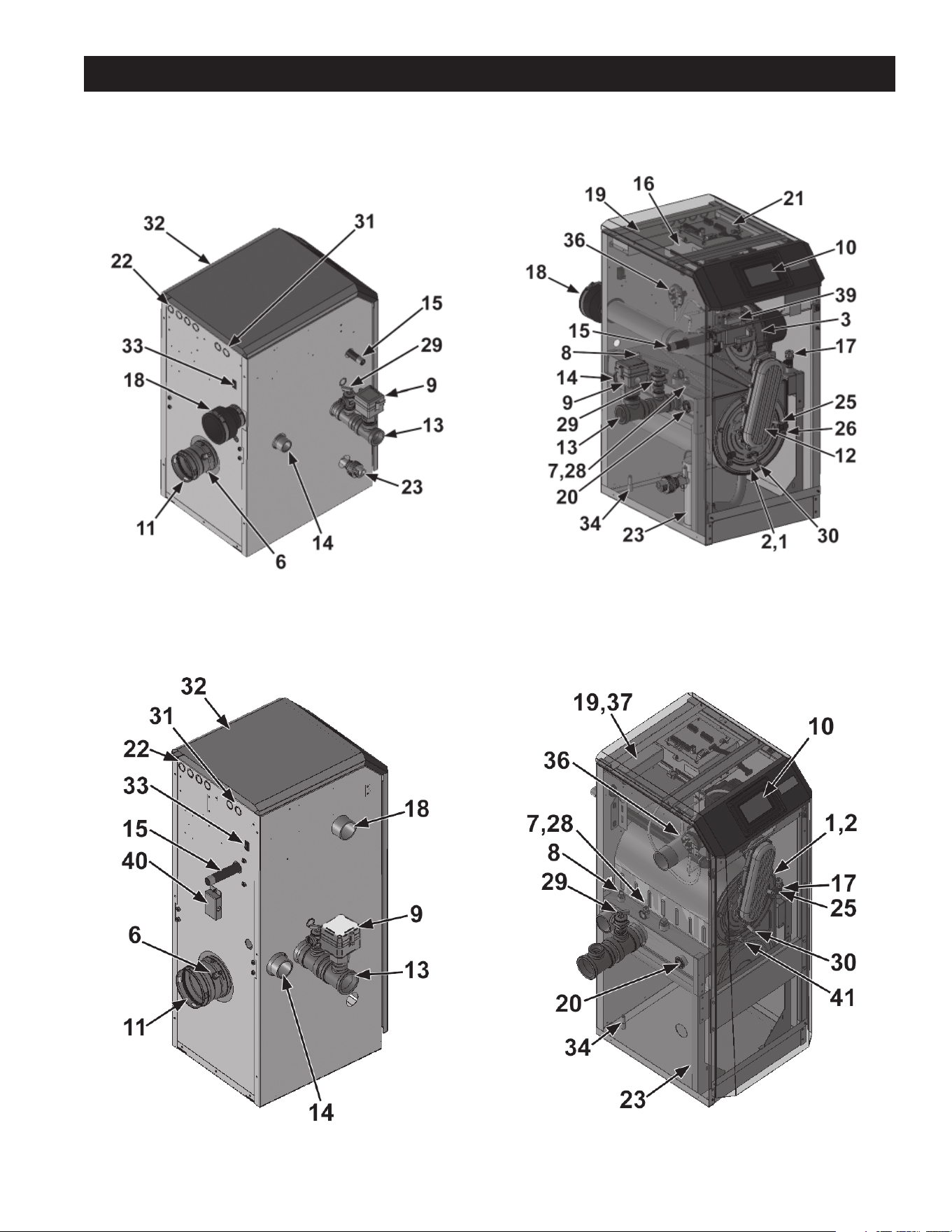
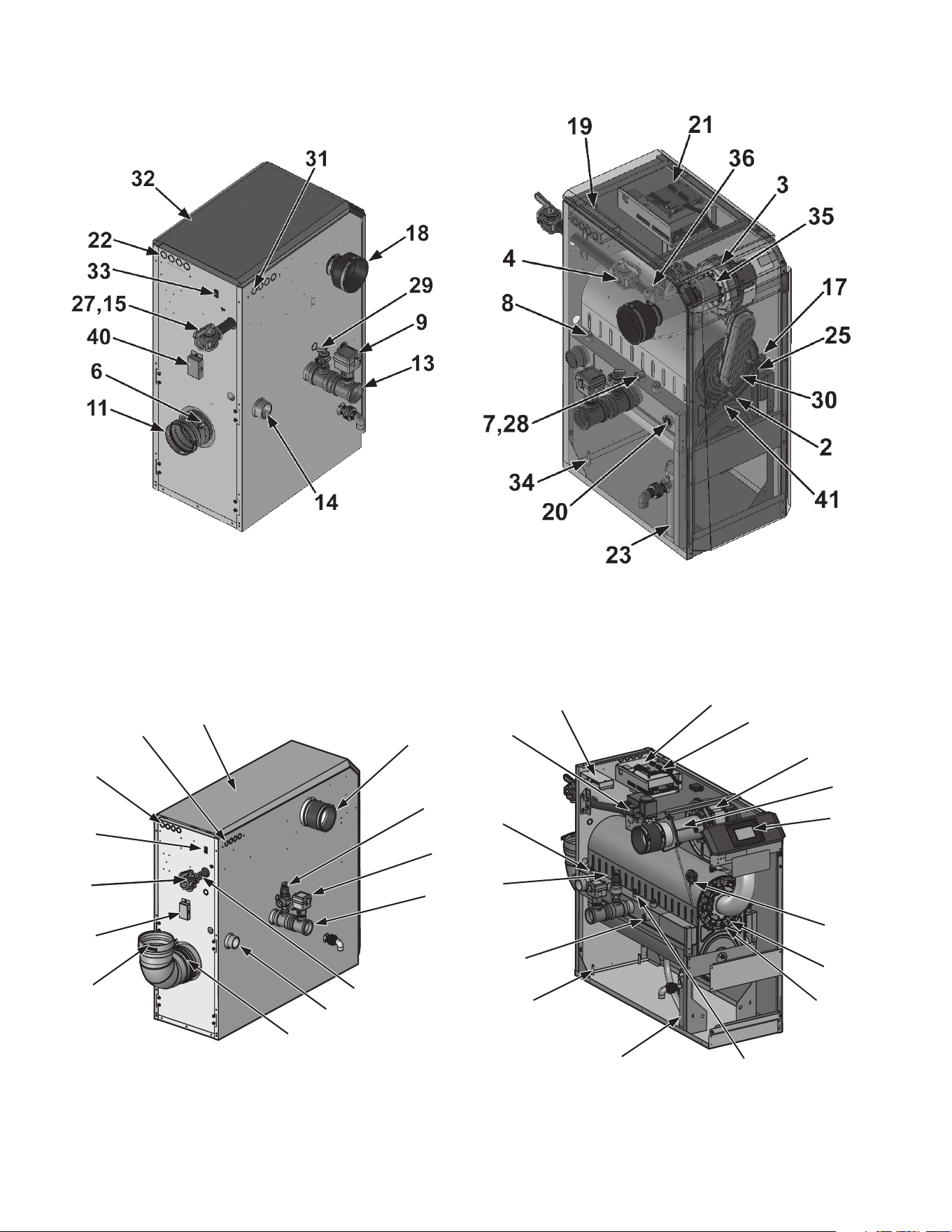
FEATURES AND COMPONENTS
Left Side (Inside Out): Models 285Rear View - Models 285
Left Side (Inside Out): Models 150 - 200Rear View - Models 150 - 200
MODELS 150 - 200
MODEL 285
8
22
18
32
31
9
29
13
33
11
40
27
14
15
6
4
8
1
16
3
21
10
36
2
41
5
23
34
20
7, 28
19
Left Side (Inside Out): Models 600 - 800Rear View - Models 600 - 800
Left Side (Inside Out): Models 400 - 500Rear View - Models 400 - 500
MODELS 400 - 500
MODELS 600 - 800

9
21. Low Voltage Connection Board: The connection board is
used to connect external low voltage devices.
22. Low Voltage Wiring Connections (Knockouts): Conduit
connection points for the low voltage connection board.
23. Condensate Drain Connection: Connects the condensate
drain line to a 1/2" PVC union.
24. Access Cover - Front (not shown): Provides access to the
gas train and the heat exchanger.
25. Ignition Electrode: Provides direct spark for igniting the
burner.
26. Flame Inspection Window: The quartz glass window
provides a view of the burner surface and fl ame.
27. Gas Shutoff Valve: Manual valve used to isolate the gas
valve from the gas supply.
28. High limit sensor (housed with the Outlet Temperature
Sensor): Device that monitors the outlet water temperature.
If the temperature exceeds its setting, the integrated control
will break the control circuit, shutting the water heater down.
29. Temperature & Pressure Relief Valve: Protects the heat
exchanger from over pressure and temperature conditions.
The T & P Relief Valve is set at 150 PSI.
30. Flame Sensor: Used by the control module to detect the
presence of burner fl ame.
31. Line Voltage Wiring Connections (Knockouts): Conduit
connection points for the high voltage junction box.
32. Top Panel: Removable panel to gain access to the internal
components.
33. Power Switch: Turns 120 VAC ON/OFF to the water heater.
34. Leveling Legs: Used to allow the heat exchanger to
be leveled. This is needed for the proper draining of the
condensate from the combustion chamber.
35. Air Shroud (500 Model Only): The air shroud directs air and
gas fl ow into the burner.
36. Air Pressure Switch: The air pressure switch detects
blocked inlet or outlet conditions.
37. Pump Relay (not shown): The pump relay is used to control
the circulation pump.
38. Transformer: The transformer provides 24V power to the
integrated control.
39. Gas Shutoff Switch: An electrical switch designed to cut
power to the gas valve to prevent releasing any gas.
40. Over-Temp Switch (Models 285 - 800) (located underneath
access cover): An electrical switch designed to shut down
water heater operation in the event the outer back of the
heat exchanger, directly above the fl ue connection exceeds
604°F (318°C). This is a one time switch and could warrant a
heat exchanger replacement. Check the integrity of the rear
refractory at the back of the upper coil if the switch opens.
41. Burner Door Temperature Switch (Models 285 - 800 Only):
An electrical switch designed to shut down water heater
operation in the event the combustion chamber access cover
exceeds 500°F (260°C). This switch may only be reset by a
qualifi ed service technician AFTER the underlying cause has
been identifi ed and corrected. Check the integrity of the front
refractory on the inside of the combustion chamber access
cover if the switch opens.
COMPONENTS
1. Stainless Steel Heat Exchanger. Allows water to fl ow
through specially designed coils for maximum heat transfer,
while providing protection against fl ue gas corrosion. The coils
are encased in a jacket that contains the combustion process.
2. Combustion Chamber Access Cover: Allows access to
the combustion side of the heat exchanger coils.
3. Blower: The blower pulls in air and gas through the venturi
(item 5). Air and gas mix inside the blower and are pushed
into the burner, where they burn inside the combustion
chamber.
4. Gas Valve: The gas valve monitors the negative pressure
created by the blower, allowing gas to fl ow only if the gas
valve is powered and combustion air is fl owing.
5. Venturi: The venturi controls air and gas fl ow into the
burner.
6. Flue Gas (limit rated): This sensor monitors the fl ue gas
exit temperature. The control module will modulate and
shut down the water heater if the fl ue gas temperature gets
too hot. This protects the fl ue pipe from overheating.
7. Water Heater Outlet Temperature Sensor (Housed with
the High Limit Sensor): This sensor monitors water heater
outlet water temperature (system supply). If selected as
the controlling sensor, the control module adjusts the water
heater fi ring rate so the outlet temperature is correct.
8. Water Heater Inlet Temperature Sensor: This sensor
monitors return water temperature (system return). If
selected as the controlling sensor, the control module adjusts
the water heater fi ring rate so the inlet temperature meets
system setpoint.
9. Flow Switch: The fl ow switch is a safety device that ensures
fl ow through the heat exchanger during operation. This
appliance is low mass and should never be operated without
fl ow. The fl ow switch makes contact when fl ow is detected
and allows the unit to operate. If fl ow is discontinued during
operation for any reason the fl ow switch will break the control
circuit and the unit will shut down.
10. Touch Screen Display: The electronic display is a Touch
Screen Display consisting of Main Menu, Help and Enable/
Disable buttons.
11. Flue Pipe Adapter: Allows for the connection of the PVC
vent pipe system to the water heater.
12. Burner (not shown): Made with metal fi ber and stainless
steel construction, the burner uses pre-mixed air and gas
and provides a wide range of fi ring rates.
13. Water Outlet: NPT water connection that supplies hot water
to the tank.
14. Water Inlet: NPT water connection that returns water from
the tank to the heat exchanger.
15. Gas Connection Pipe: Threaded pipe connection. This
pipe should be connected to the incoming gas supply for the
purpose of delivering gas to the water heater.
16. Control Module: The Control Module responds to internal
and external signals and controls the blower, gas valve, and
pumps to meet the demand.
17. Manual Air Vent: Designed to remove trapped air from the
heat exchanger coils.
18. Air Intake Adapter: Allows for the connection of the PVC air
intake pipe to the water heater.
19. High Voltage Junction Box: The junction box contains the
connection points for the line voltage power and the pump.
20. Water Heater Drain Port: Location from which the heat
exchanger can be drained.
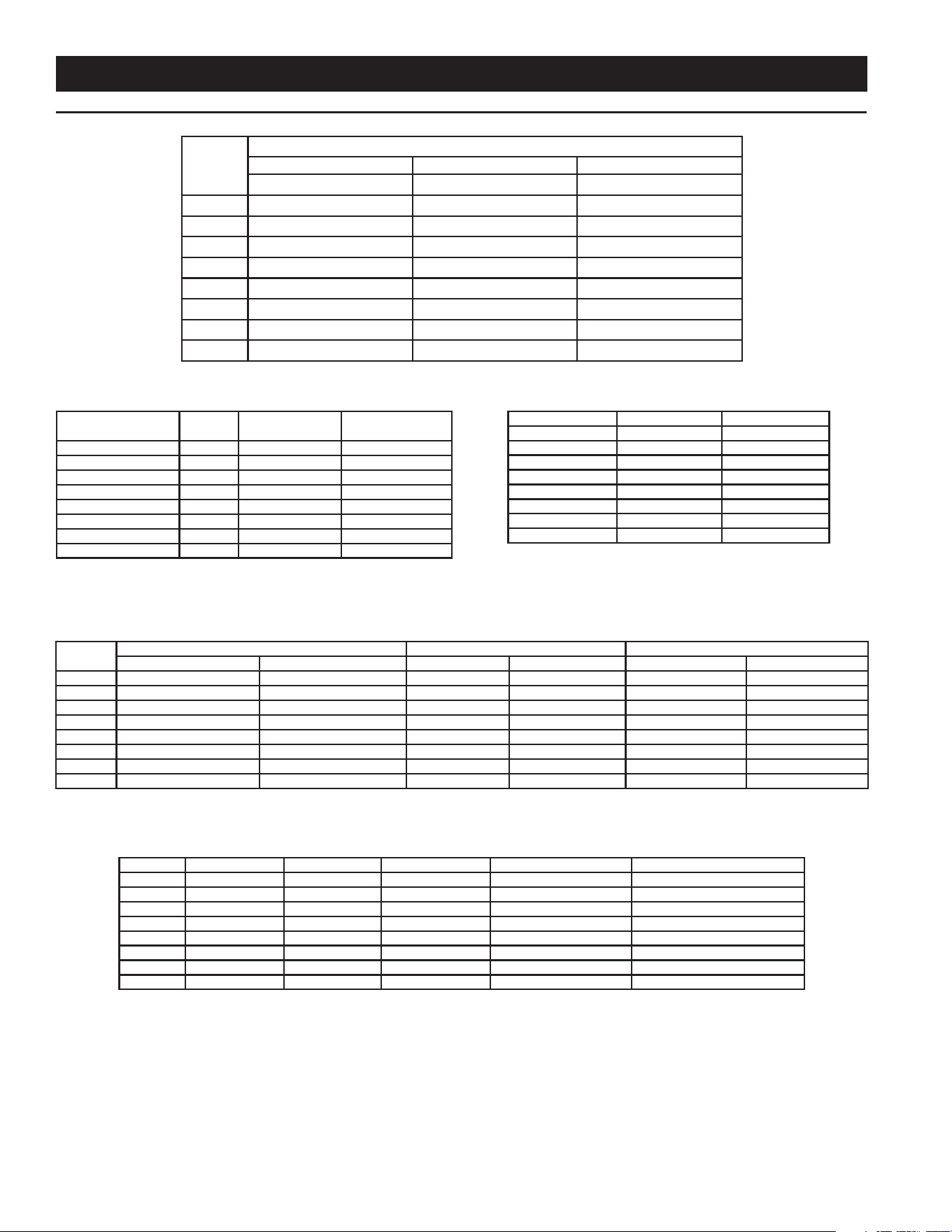
10
INSTALLATION CONSIDERATIONS
MODEL
DIMENSIONS
HEIGHT WIDTH DEPTH
INCHES (CM) INCHES (CM) INCHES (CM)
XWH 150 33-1/4" (84.5) 15-1/2" (39.4) 18" (45.72)
XWH 200 33-1/4" (84.5) 15-1/2" (39.4) 22-1/4" (56.5)
XWH 285 42-1/2" (107.95) 15-1/2" (39.4) 19-3/4" (50.2)
XWH 400 42-1/2" (107.95) 15-1/2" (39.4) 27" (68.6)
XWH 500 42-1/2" (107.95) 15-1/2" (39.4) 31-1/4" (79.4)
XWH 600 42-1/2" (107.95) 15-1/2" (39.4) 36-1/4" (92.1)
XWH 700 42-1/2" (107.95) 15-1/2" (39.4) 40-1/4" (102.2)
XWH 800 42-1/2" (107.95) 15-1/2" (39.4) 42-1/4" (107.3)
GAS LINE CONNECTION SIZE
TABLE 2
† MODEL SERIES NATURAL GAS
NPT
PROPANE GAS
NPT
XWH 150 100 1/2” 1/2”
XWH 200 100 1/2” 1/2”
XWH 285 100 3/4" 3/4"
XWH 400 100 1" 1"
XWH 500 100 1" 1"
XWH 600 100 1" 1"
XWH 700 100 1" 1"
XWH 800 100 1" 1"
† Depending on the installed equivalent length, and/or the number of appliances connected,
the supply gas line size may have to be increased beyond the minimum required sizes - see
Table 23 on Page 44.
STORAGE CAPACITIES
TABLE 3
MODEL U. S. GALLONS LITERS
XWH 150 1.3 4.9
XWH 200 1.7 6.4
XWH 285 2.4 9.1
XWH 400 3.4 12.9
XWH 500 4.2 15.9
XWH 600 4.2 15.9
XWH 700 5.0 18.9
XWH 800 5.7 21.6
GAS PRESSURE REQUIREMENTS
TABLE 4
MODEL
*MANIFOLD PRESSURE MINIMUM SUPPLY PRESSURE MAXIMUM SUPPLY PRESSURE
NATURAL GAS PROPANE GAS NATURAL GAS PROPANE GAS NATURAL GAS PROPANE GAS
XWH 150 -0.22” W.C. (-0.054 kPa) -0.23” W.C. (-0.057 kPa) 4” W. C. (1 kPa) 8” W. C. (2 kPa) 14” W. C. (3.49 kPa) 14” W. C. (3.49 kPa)
XWH 200 -0.39” W.C. (-0.09 kPa) -0.39” W.C. (-0.09 kPa) 4” W. C. (1 kPa) 8” W. C. (2 kPa) 14” W. C. (3.49 kPa) 14” W. C. (3.49 kPa)
XWH 285 -0.68” W.C. (-0.17 kPa) -0.71” W.C. (-0.18 kPa) 4” W. C. (1 kPa) 8” W. C. (2 kPa) 14” W. C. (3.49 kPa 14” W. C. (3.49 kPa)
XWH 400 -1.45” W.C. (-0.36 kPa) -1.40” W.C. (-0.35 kPa) 4” W. C. (1 kPa) 8” W. C. (2 kPa) 14” W. C. (3.49 kPa) 14” W. C. (3.49 kPa)
XWH 500 -0.20” W.C. (-0.05 kPa) -0.20” W.C. (-0.05 kPa) 4” W. C. (1 kPa) 8” W. C. (2 kPa) 14” W. C. (3.49 kPa) 14” W. C. (3.49 kPa)
XWH 600 -2.17” W.C. (-0.54 kPa) -2.72” W.C. (-0.67 kPa) 4” W. C. (1 kPa) 8” W. C. (2 kPa) 14” W. C. (3.49 kPa) 14” W. C. (3.49 kPa)
XWH 700 -2.97” W.C. (-0.74 kPa) -3.58” W.C. (-0.89 kPa) 4” W. C. (1 kPa) 8” W. C. (2 kPa) 14” W. C. (3.49 kPa 14” W. C. (3.49 kPa)
XWH 800 -3.50” W.C. (-0.88 kPa) -4.30” W.C. (-1.1 kPa) 4” W. C. (1 kPa) 8” W. C. (2 kPa) 14” W. C. (3.49 kPa) 14” W. C. (3.49 kPa)
* The manifold pressure is the factory setting and is not adjustable. A negative pressure will be seen with just the blower running without the Gas Control Valve open.
ELECTRICAL REQUIREMENTS
TABLE 5
Model Voltage/ Heater Voltage/ Pump Voltage/ Control Total AMPS W/ Pump # Of Electrical Connections
XWH 150 120 120 24 3.0 1
XWH 200 120 120 24 3.2 1
XWH 285 120 120 24 4.5 1
XWH 400 120 120 24 6.5 1
XWH 500 120 120 24 5.7 1
XWH 600 120 120 24 5.7 1
XWH 700 120 120 24 12.8 1
XWH 800 120 120 24 12.8 1
ROUGH IN DIMENSIONS
TABLE 1
11
4. The XP water heater must be installed so that gas control
system components are protected from dripping or spraying
water or rain during operation or service.
5. If a new water heater will replace an existing water heater,
check for and correct system problems, such as:
• System leaks causing oxygen corrosion or heat
exchanger cracks from hard water deposits.
6. Check around the water heater for any potential air
contaminants that could risk corrosion to the water heater
or the water heater combustion air supply (refer to the list
on Page 14). Prevent combustion air contamination. Remove
any of these contaminants from the water heater area.
This appliance is certifi ed as an indoor appliance. Do not install
the appliance outdoors or locate where the appliance will be
exposed to freezing temperatures or to temperatures that exceed
100°F.
Do not install the appliance where the relative humidity may
exceed 93%. Do not install the appliance where condensation
may form on the inside or outside of the appliance, or where
condensation may fall onto the appliance. Failure to install the
appliance indoors could result in severe personal injury, death,
or substantial property damage.
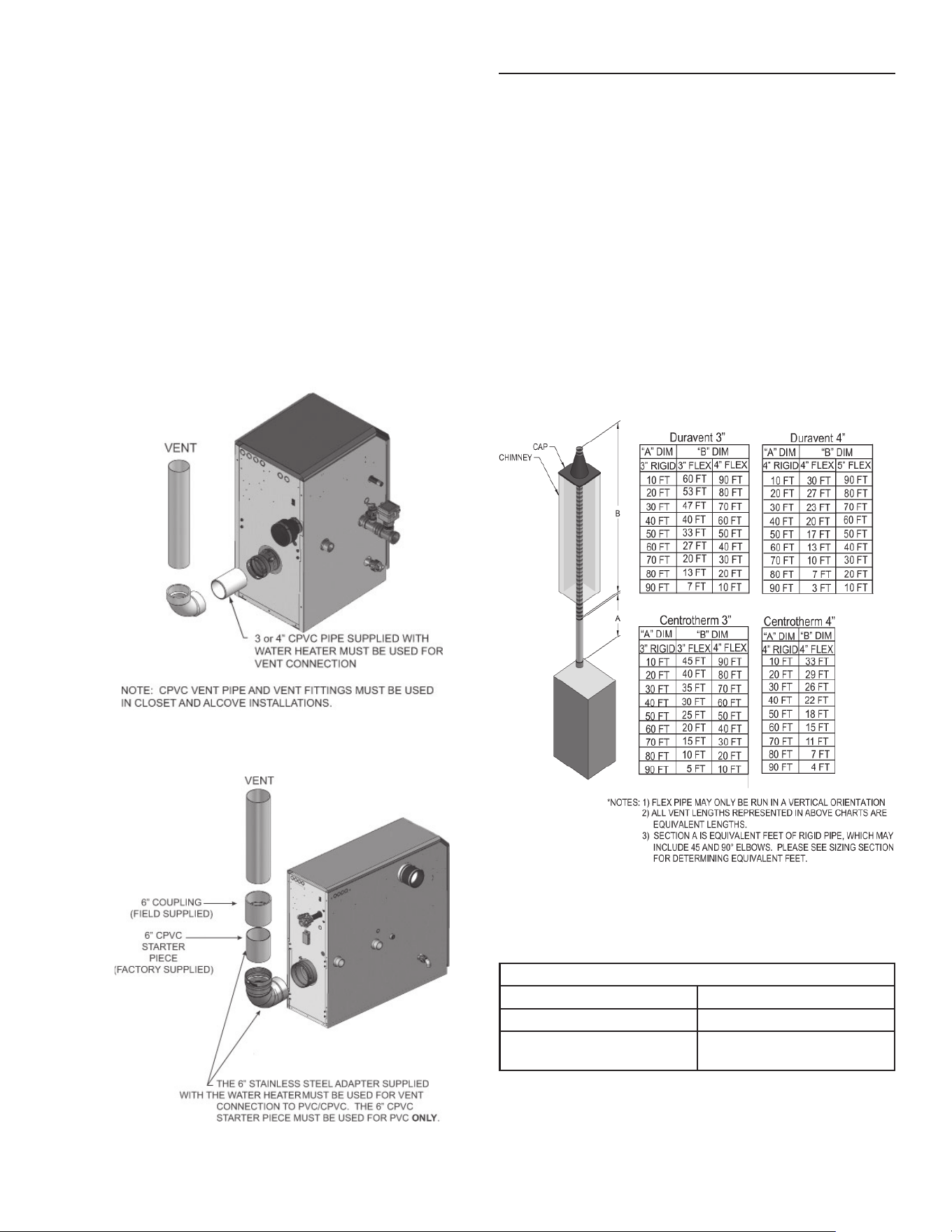
This appliance requires a special venting system. If using PVC
the vent connection to the appliance must be made with the
starter CPVC pipe section provided with the appliance. The
fi eld provided vent fi ttings must be cemented to the CPVC pipe
section. Use only the vent materials, primer and cement specifi ed
in this manual to make the vent connections. Failure to follow this
warning could result in fi re, personal injury, or death.
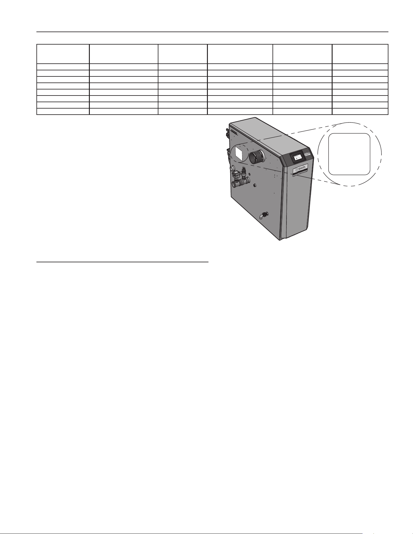
RATINGS
TABLE 6
MODEL NUMBER CSA INPUT MODULATION
BTU/HR
(NOTE 2, 3)
WATER CONTENT
GALLONS
WATER CONNECTIONS GAS CONNECTIONS VENT/AIR SIZE
(NOTE 1, 5)
XWH 150 30,000 - 150,000 1.3 1-1/4" NPT 1/2" 3"/3"
XWH 200
39,800 - 199,000
1.7 1-1/4" NPT 1/2" 3"/3"
XWH 285 57,000 - 285,000 2.4 2" NPT 3/4" 4"/4"
XWH 400
79,800 - 399,000
3.4 2" NPT 1" 4"/4"
XWH 500 100,000 - 500,000 4.2 2" NPT 1" 4"/4"
XWH 600 120,000 - 600,000 4.2 2" NPT 1" 4"/4"
XWH 700 140,000 - 700,000 5.0 2" NPT 1" 6"/4"
XWH 800 160,000 - 800,000 5.7 2" NPT 1" 6"/4"
Notice: Maximum allowed working pressure is located on the rating plate.
1. All XP water heaters require special exhaust venting. Use only the vent
materials and methods specifi ed in this Instruction Manual.
2. Standard XP water heaters are equipped to operate from sea level to 4,500
feet only with no adjustments. The water heater will de-rate by 4% for each
1,000 feet above sea level up to 4,500 feet.
3. High altitude XP water heaters are equipped to operate from 3,000 to 12,000
feet only. The water heater will de-rate by 2% for each 1,000 feet above sea
level. High altitude models are manufactured with a different control module for
altitude operation, but the operation given in this manual remains the same as
the standard models. A high altitude label (as shown in Figure 1) is also affi xed
to the unit.
Derate values are based on proper combustion calibration and CO2’s adjusted
to the recommended levels.
4. The manual reset high limit provided with the XP is listed to UL353. The auto
reset high limit is listed to ANSI Z21.87.
5. The XWH 285 model can be alternatively vented using a 3” vent/air size. If
the 3” vent/air size is used, the maximum vent/air pipe lengths are limited to 60
equivalent feet each.
UNIT EQUIPPED FOR
HIGH ALTITUDE
3,000 FT TO 12,000 FT
Figure 1. High Altitude Label Location
DETERMINE WATER HEATER LOCATION
INSTALLATION MUST COMPLY WITH:
• Local, state, provincial, and national codes, laws,
regulations, and ordinances.
• National Fuel Gas Code, ANSI Z223.1 – latest edition.
• National Electrical Code.
NOTE: The XP water heater gas manifold and controls met safe
lighting and other performance under tests specifi ed in ANSI
Z21.10.3 – latest edition.
BEFORE LOCATING THE WATER HEATER, CHECK:
1. Check for nearby connection to:
• Water piping
• Venting connections
• Gas supply piping
• Electrical power
2. Locate the appliance so that if water connections should
leak, water damage will not occur. When such locations
cannot be avoided, it is recommended that a suitable drain
pan, adequately drained, be installed under the appliance.
The pan must not restrict combustion air fl ow. Under no
circumstances is the manufacturer to be held responsible for
water damage in connection with this appliance, or any of its
components.
3. Check area around the water heater. Remove any
combustible materials, gasoline and other fl ammable liquids.
Failure to keep water heater area clear and free of combustible
materials, gasoline, and other fl ammable liquids and vapors can
result in severe personal injury, death, or substantial property
damage.
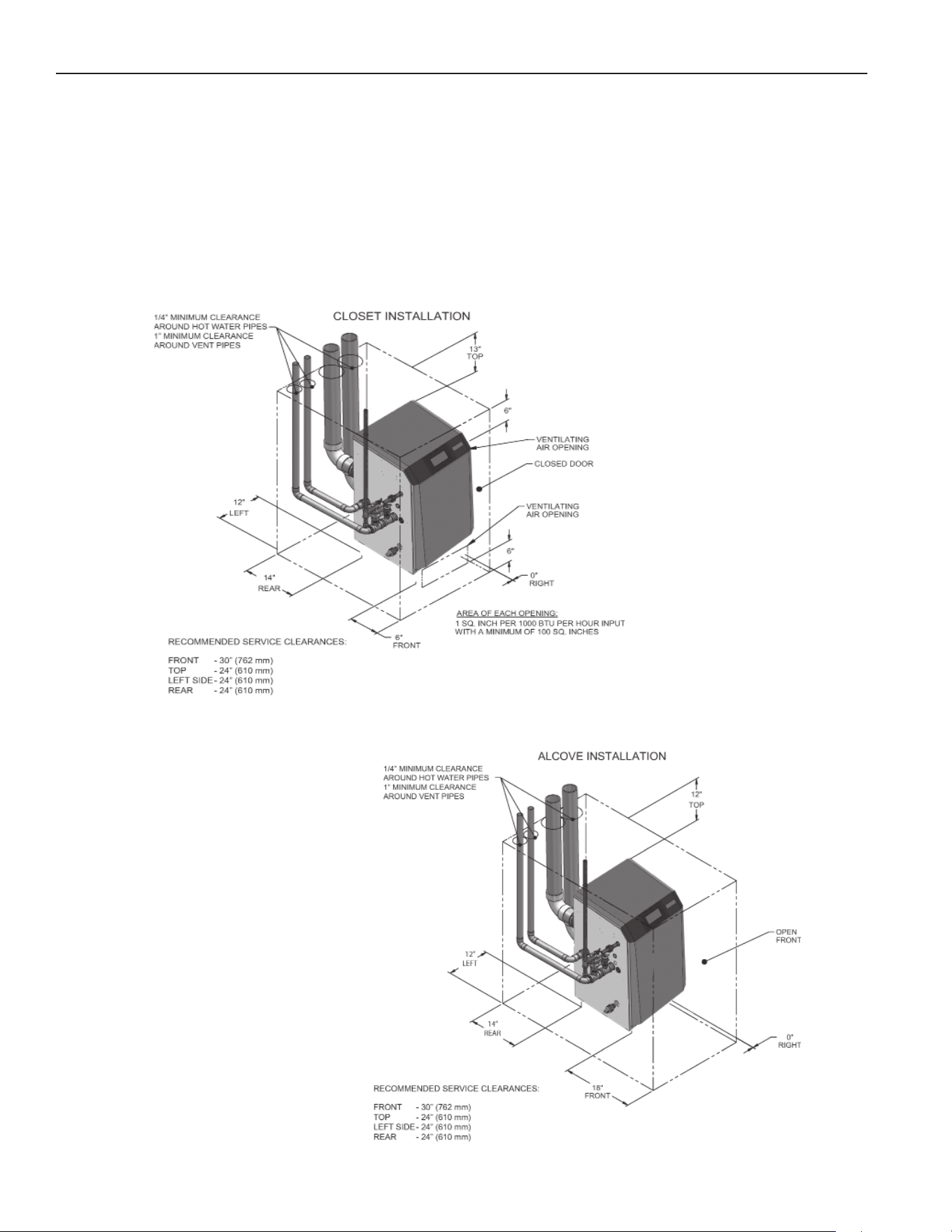
12
CLOSET AND ALCOVE INSTALLATIONS
A closet is any room the water heater is installed in which is less
than 86 cubic feet for XWH 150 models, 106 cubic feet for XWH
200 models, 120 cubic feet for XWH 285 models, 165 cubic feet
for XWH 400 models, 191 cubic feet for XWH 500 models, 223
cubic feet for XWH 600 models, 247 cubic feet for XWH 700
models and 278 cubic feet for XWH 800 models. An alcove is
any room which meets the criteria for a closet with the exception
that it does not have a door. For closet and alcove installations
as shown in below Figures 2 & 3, CPVC vent material must be
used inside the structure. The ventilating air openings shown in
Figures 2 & 3 are required for this arrangement. Failure to follow
this warning could result in fi re, personal injury, or death.
PROVIDE CLEARANCES:
Clearances from combustible materials
1. Hot water pipes—at least 1/4" from combustible materials.
2. Vent pipe – at least 1" from combustible materials.
3. See Figure’s 2 and 3 below for other clearance minimums.
Clearances for service access
1. See Figure’s 2 and 3 below for recommended service
clearances. If you do not provide the minimum clearances
shown, it may not be possible to service the water heater
without removing it from the space.
For closet installations, CPVC,
polypropylene or stainless steel
vent material MUST BE used in
a closet structure due to elevated
temperatures. Failure to follow this
warning could result in fi re, personal
injury, or death.
For alcove installations, CPVC,
polypropylene or stainless steel
vent material MUST BE used in
a closet structure due to elevated
temperatures. Failure to follow this
warning could result in fi re, personal
injury, or death.
Figure 2. Closet Installation - Minimum Required Clearances
Figure 3. Alcove Installation - Minimum Required Clearances

13
VENT AND AIR PIPING
The XP water heater requires a special vent system, designed
for pressurized venting.
The water heater is to be used for either direct vent installation
or for installation using indoor combustion air. When room air is
considered, see the Venting Installation section. Note prevention
of combustion air contamination below when considering vent/
air termination.
Exhaust vent and combustion air pipes must terminate near one
another and may be vented vertically through the roof or out a
side wall, unless otherwise specifi ed. You may use any of the
vent/air piping methods covered in this manual. Do not attempt
to install the XP water heater using any other means.
Be sure to locate the water heater such that the vent and air piping
can be routed through the building and properly terminated. The
vent/air piping lengths, routing and termination method must all
comply with the methods and limits given in this manual.
PREVENT COMBUSTION AIR CONTAMINATION
Install air inlet piping for the XP water heater as described in
this manual. Do not terminate vent/air in locations that can allow
contamination of combustion air. Refer to the list on Page 14 for
products and areas which may cause contaminated combustion
air. In case, if any of these contaminants are stored in the
same room, the water heater must be installed in a direct vent
application.
You must pipe combustion air to the water heater air intake.
Ensure that the combustion air will not contain any of the
contaminants listed on Page 14. Contaminated combustion
air will damage the water heater, resulting in possible severe
personal injury, death or substantial property damage. Do not
pipe combustion air near a swimming pool, for example. Also
avoid areas subject to exhaust fumes from laundry facilities.
These areas will always contain contaminants.
PROVIDE AIR OPENINGS TO ROOM:
XP water heater alone in equipment room
1. No air ventilation openings into the equipment room are
needed when clearances around the XP water heater are at
least equal to the SERVICE clearances shown in Figure’s
2 and 3. For spaces that do NOT supply this clearance,
provide two openings as shown in Figure 2. Each opening
must provide one square inch free area per 1,000 Btu/hr of
water heater input.
XP water heater in same space with other gas or oil-fi red
appliances
1. Follow the National Fuel Gas Code (U.S.) to size/verify size
of the combustion/ventilation air openings into the space.
The space must be provided with combustion/ ventilation air
openings correctly sized for all other appliances located in the
same space as the XP water heater.
Do not install the water heater in an attic.
Failure to comply with the above warnings could result in severe
personal injury, death, or substantial property damage.
2. Size openings only on the basis of the other appliances in
the space. No additional air opening free area is needed for
the XP water heater because it takes its combustion air from
outside (direct vent installation).
FLOORING AND FOUNDATION
Flooring
The XP water heater is approved for installation on combustible
fl ooring, but must never be installed on carpeting.
Do not install the water heater on carpeting even if foundation is
used. Fire can result, causing severe personal injury, death, or
substantial property damage.
If fl ooding is possible, elevate the water heater suffi ciently to
prevent water from reaching the water heater.
RESIDENTIAL GARAGE INSTALLATION
Precautions
Take the following precautions when installing the appliance in
a residential garage. If the appliance is located in a residential
garage, it should be installed in compliance with the latest
edition of the National Fuel Gas Code, ANSI Z223.1 and/or CAN/
CGA-B149 Installation Code.
• Appliances located in residential garages and in adjacent
spaces that open to the garage and are not part of the
living space of a dwelling shall be installed so that all
burners and burner ignition devices are located not less
than 18 inches (46 cm) above the fl oor.
• The appliance shall be located or protected so that it is
not subject to physical damage by a moving vehicle.

14
• Seal - With prior requirements met, the system should be
tested to the procedure listed in parts (3) through (6) of the
Removal of an Existing Water Heater section mentioned
below.
With polypropylene and stainless steel vent, seal and connect
all pipe and components as specifi ed by the vent manufacturer
used; with PVC/CPVC vent, see the Installing Vent and Air Piping
section on Page 20. If any of these conditions are not met, the
existing system must be updated or replaced for that concern.
Failure to follow all instructions can result in fl ue gas spillage and
carbon monoxide emissions, causing severe personal injury or
death.
WHEN REMOVING A WATER HEATER FROM
EXISTING COMMON VENT SYSTEM
Do not install this water heater into a common vent with any
other appliance. This will cause fl ue gas spillage or appliance
malfunction, resulting in possible severe personal injury, death,
or substantial property damage. Failure to follow all instructions
can result in fl ue gas spillage and carbon monoxide emissions,
causing severe personal injury or death.
At the time of removal of an existing water heater, the following
steps shall be followed with each appliance remaining connected
to the common venting system placed in operation, while the
other appliances remaining connected to the common venting
system are not in operation.
1. Seal any unused openings in the common venting system.
2. Visually inspect the venting system for proper size and
horizontal pitch and determine there is no blockage or
restriction, leakage, corrosion, or other defi ciencies, which
could cause an unsafe condition.
3. Test vent system – Insofar as is practical, close all building
doors and windows and all doors between the space in which
the appliances remaining connected to the common venting
system are located and other spaces of the building. Turn
on clothes dryers and any appliance not connected to the
common venting system. Turn on any exhaust fans, such as
range hoods and bathroom exhausts, so they will operate
at maximum speed. Do not operate a summer exhaust fan.
Close fi replace dampers.
4. Place in operation the appliance being inspected. Follow
the lighting instructions. Adjust thermostat so appliance will
operate continuously.
5. Test for spillage at the draft hood relief opening after 5
minutes of main burner operation. Use the fl ame of a match
or candle, or smoke from a cigarette, cigar, or pipe.
6. After it has been determined that each appliance remaining
connected to the common venting system properly vents
when tested as outlined herein, return doors, windows,
exhaust fans, fi replace dampers, and any other gas-burning
appliance to their previous conditions of use.
7. Any improper operation of the common venting system
should be corrected so the installation conforms with the
National Fuel Gas Code, ANSI Z223.1/NFPA 54 and/or
CAN/CSA B149.1, Natural Gas and Propane Installation
Code. When resizing any portion of the common venting
system, the common venting system should be resized
to approach the minimum size as determined using the
appropriate tables in Part 11 of the National Fuel Gas Code,
ANSI Z223.1/NFPA and/or CAN/CSA B149.1, Natural Gas
and Propane Installation Code.
CORROSIVE MATERIALS AND CONTAMINATION
SOURCES
Products to avoid:
• Spray cans containing chloro/fl uorocarbons
• Permanent wave solutions
• Chlorinated waxes/cleaners
• Chlorine-based swimming pool chemicals
• Calcium chloride used for thawing
• Sodium chloride used for water softening
• Refrigerant leaks
• Paint or varnish removers
• Hydrochloric acid/muriatic acid
• Cements and glues
• Antistatic fabric softeners used in clothes dryers
• Chlorine-type bleaches, detergents, and cleaning
solvents found in household laundry rooms
• Adhesives used to fasten building products and other
similar products
Areas likely to have contaminants:
• Dry cleaning/laundry areas and establishments
• Swimming pools
• Metal fabrication plants
• Beauty shops
• Refrigeration repair shops
• Photo processing plants
• Auto body shops
• Plastic manufacturing plants
• Furniture refi nishing areas and establishments
• New building construction
• Remodeling areas
• Garages with workshops
WHEN USING AN EXISTING VENT SYSTEM TO
INSTALL A NEW WATER HEATER
Check the following venting components before installing:
• Material - For materials listed for use with this appliance, see
Venting Installation section on Page 17. For polypropylene or
stainless steel venting, an adapter of the same manufacturer
must be used at the fl ue collar connection.
• Size - To ensure proper pipe size is in place, see Table
8. Check to see that this size is used throughout the vent
system.
• Manufacturer - For a stainless steel or polypropylene
application, you must use only the listed manufacturers
and their type product listed in Tables 12 and 14 for CAT
IV positive pressure venting with fl ue producing condensate.
• Supports - Non-combustible supports must be in place
allowing a minimum 1/4" rise per foot. The supports should
adequately prevent sagging and vertical slippage, by
distributing the vent system weight. For additional information,
consult the vent manufacturer’s instructions for installation.
• Terminations - Carefully review Venting Installation section
to ensure requirements for the location of the vent and
air terminations are met and orientation of these fi t the
appropriate image from the Horizontal or Vertical options
listed in the Venting Installation section. For stainless
steel vent, only use terminations listed in Table 16 for the
manufacturer of the installed vent.
15
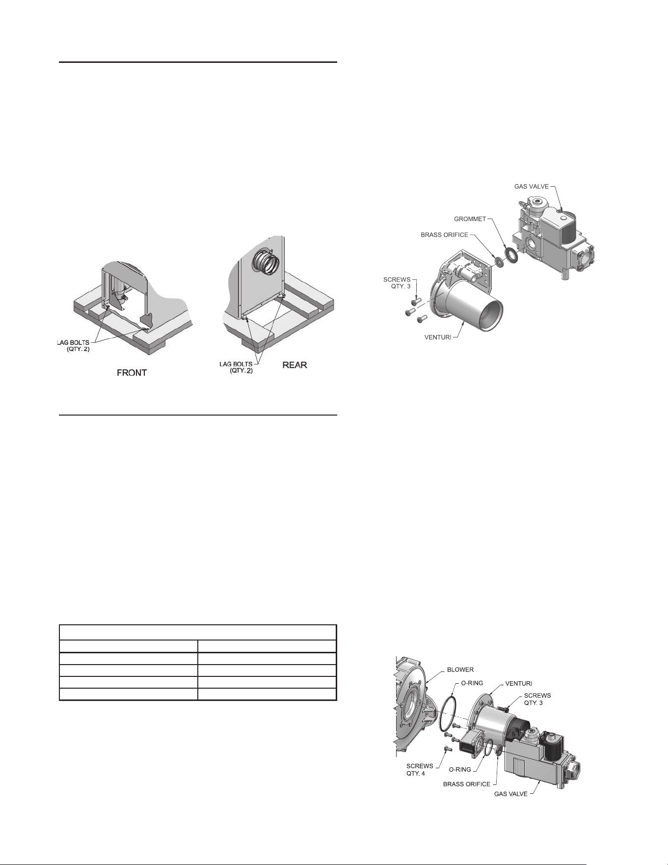
4. Reposition the gas valve against the venturi and replace the
screws (See Figure 5) securing the valve to the venturi.
5. After installation is complete, attach the propane conversion
label (in the conversion kit bag) next to the water heater
rating plate. Attach the Propane (LP) caution label (in the
conversion kit bag) to the left side of the unit in the lower
left corner.
6. Replace the top and front access covers.
After converting to Propane (LP), check combustion per the
Start-up procedure on Page 50 of this manual. Failure to check
and verify combustion could result in severe personal injury,
death, or substantial property damage.
Figure 5. Installing Propane Orifi ce - Models 150-285
Model 400:
1. Remove the top and front access covers from the unit
(no tools required for removal).
2. Remove the three screws securing the venturi to the
blower.
Note: When separating the venturi from the blower, take care
not to damage the O-ring inside the blower (see Figure 6).
3. Remove the four screws securing the gas valve to the
venturi (see Figure below).
4. Locate the propane orifice disk from the conversion kit
bag. Verify that the stamping on the orifice disk matches
the water heater size (see Table 7).
5. Remove the existing orifice from the O-ring in the side of
the gas valve and replace it with the orifice from the kit.
Position and secure the orifice in the valve as shown in
Figure below.
6. Reposition the gas valve against the venturi and replace
the screws (see Figure below) securing the valve to the
venturi.
7. Inspect the O-ring inside the blower. Handle the O-ring
with care, do not damage. Reposition the venturi against
the blower and replace the screws securing the venturi
to the blower (see Figure below).
REMOVING A WATER HEATER FROM WOOD
PALLET
1. After removing the outer shipping carton from the water
heater, remove the parts box.
2. Remove the front door to access the lag bolts in front of the
unit (see Figure below).
3. To remove the water heater from the pallet (after removing
the front door):
• Remove the two lag bolts from the wood pallet inside the
water heater. See Figure below.
• Detach the water heater from the lag bolts in the rear of
the unit, see Figure below.
Do not drop the water heater or bump the jacket on the fl oor or
pallet. Damage to the water heater can result.
Figure 4. Water Heater Mounting on Shipping Pallet
GAS CONVERSIONS
NOTE: The gas conversions for all the units must only be
performed by a qualifi ed service technician.
The use of double-wall vent or insulated material for the For a
water heater already installed, you must turn off gas supply, turn
off power and allow the water heater to cool before proceeding.
You must also completely test the water heater after conversion
to verify performance as described under Start Up section of this
manual. Failure to comply could result in severe personal injury,
death, or substantial property damage.
For Models 150 - 400 you must install a propane orifi ce to operate
the XP water heater on propane gas. Verify when installing that
the orifi ce size marking matches water heater size (Models 150–
400, See Table below). The 500 - 800 Models do not require an
orifi ce installation for propane operation, but they will require a
valve adjustment.
TABLE 7
Propane (LP) Conversion Table
Model Propane (LP) Orifi ce Stamping
150 150
200 210/ W150
285 285
400 8.0
Models 150 - 285:
1. Remove the top and front access covers from the unit
(no tools required for removal).
2. Remove the three screws securing the gas valve to the
venturi. See Figure 5.
3. Locate the propane orifi ce disk from the conversion kit bag.
Verify that the stamping on the orifi ce disk matches the
water heater size (150 – 285) (see Table above).
Place the orifi ce into the black rubber grommet in the side of
the gas valve and secure in the valve (See Figure 5).
Figure 6. Installing Propane Orifi ce - Model 400
16
5. After adjustment is complete, attach the propane
conversion label (in the conversion kit bag) next to
the water heater rating plate. Attach the Propane (LP)
caution label (in the conversion kit bag) to the left side of
the unit in the lower left corner.
6. Replace the gas valve cover along with the top access
cover.
After converting to Propane (LP), check combustion per the
Start-up procedure on Page 50 of this manual. Failure to
check and verify combustion could result in severe personal
injury, death, or substantial property damage.
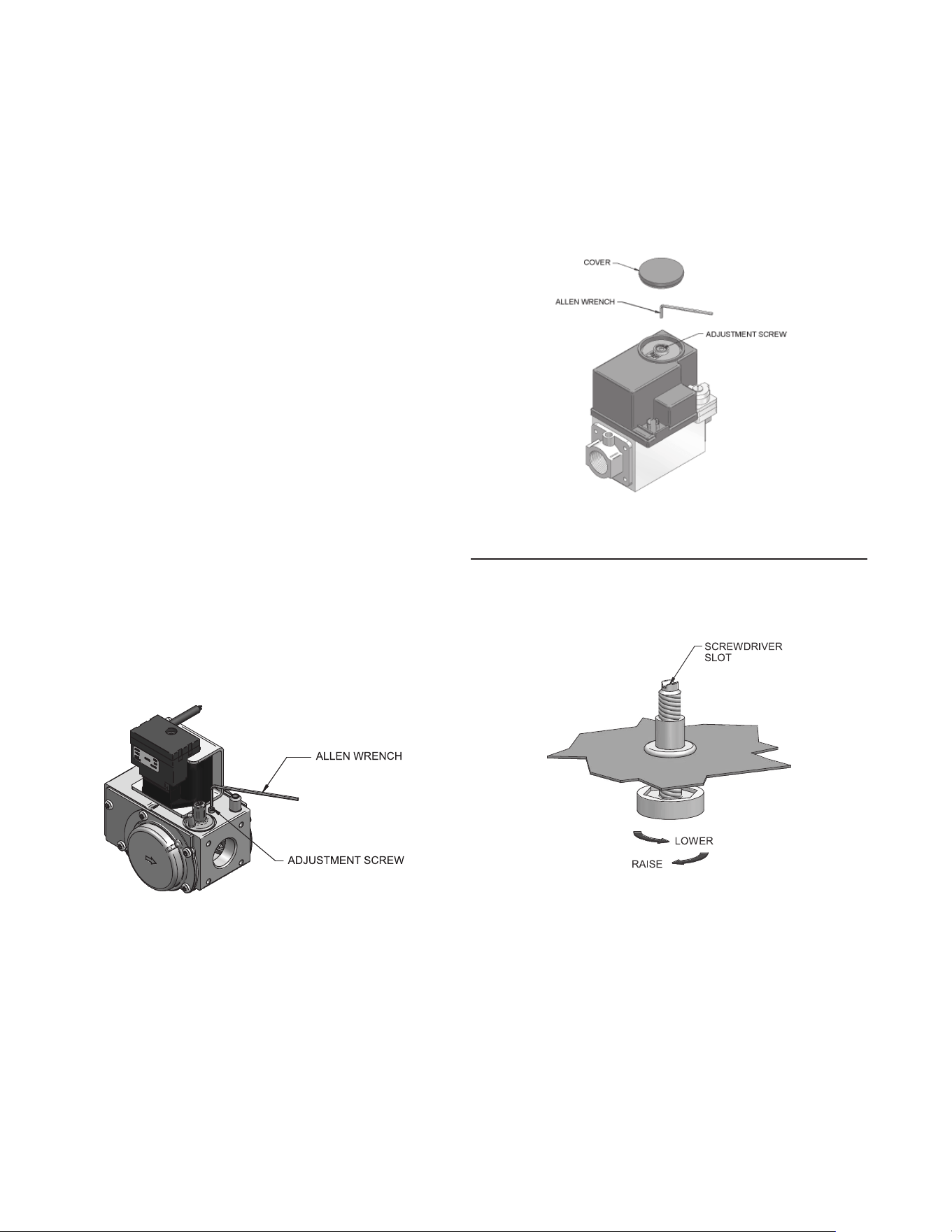
Figure 8. Gas Valve Adjustment - Model 600-800
LEVELING THE WATER HEATER
1. Set the water heater in place and check level.
• Adjust legs if necessary to level the water heater, see
Figure below.
Figure 9. Leveling Legs on the Water Heater
8. After installation is complete, attach the propane
conversion label (in the conversion kit bag) next to
the water heater rating plate. Attach the Propane (LP)
caution label (in the conversion kit bag) to the left side of
the unit in the lower left corner.
9. Replace the top and front access covers.
After converting to Propane (LP), check combustion per the
Start Up section on Page 50 of this manual. Failure to check and
verify combustion could result in severe personal injury, death, or
substantial property damage.
For XWH 400: Inspect the O-ring when the blower is
disassembled. The O-ring must be in good condition and must
be installed. Failure to comply will cause a gas leak, resulting in
severe personal injury or death.
Model 500:
1. Remove the top access covers from the unit (no tools
required for removal).
2. Turn the adjustment screw on the gas valve clockwise
until it stops. Then turn the adjustment screw
counterclockwise four and three quarter (4-3/4) turns
(see Figure below).
3. Use a combustion analyzer to verify CO2 is within
the range of 9.6 – 10.5%. If not, adjust the screw
counterclockwise incrementally to raise CO2 and
clockwise to lower CO2 (see Figure below).
4. After adjustment is complete, attach the propane
conversion label (in the conversion kit bag) next to
the water heater rating plate. Attach the Propane (LP)
caution label (in the conversion kit bag) to the left side of
the unit in the lower left corner.
5. Replace the top access cover.
After converting to Propane (LP), check combustion per the Start
Up section of this manual. Failure to check and verify combustion
could result in severe personal injury, death, or substantial
property damage.
Figure 7. Gas Valve Adjustment - Model 500
Model 600 - 800:
1. Remove the top access covers from the unit (no tools
required for removal).
2. Remove the cover on top of the gas valve (see Figure 8).
3. Turn the adjustment screw on top of the gas valve
clockwise one and three quarter (1 3/4) turns on the 600
Model, one and a half (1 1/2) turns on the 700 Model,
and one turn on the 800 Model (see Figure 8).
4. Use a combustion analyzer to verify CO2 is within
the range of 9.6 – 10.5%. If not, adjust the screw
counterclockwise incrementally to raise CO2 and
clockwise to lower CO2 (see Figure 8).
17
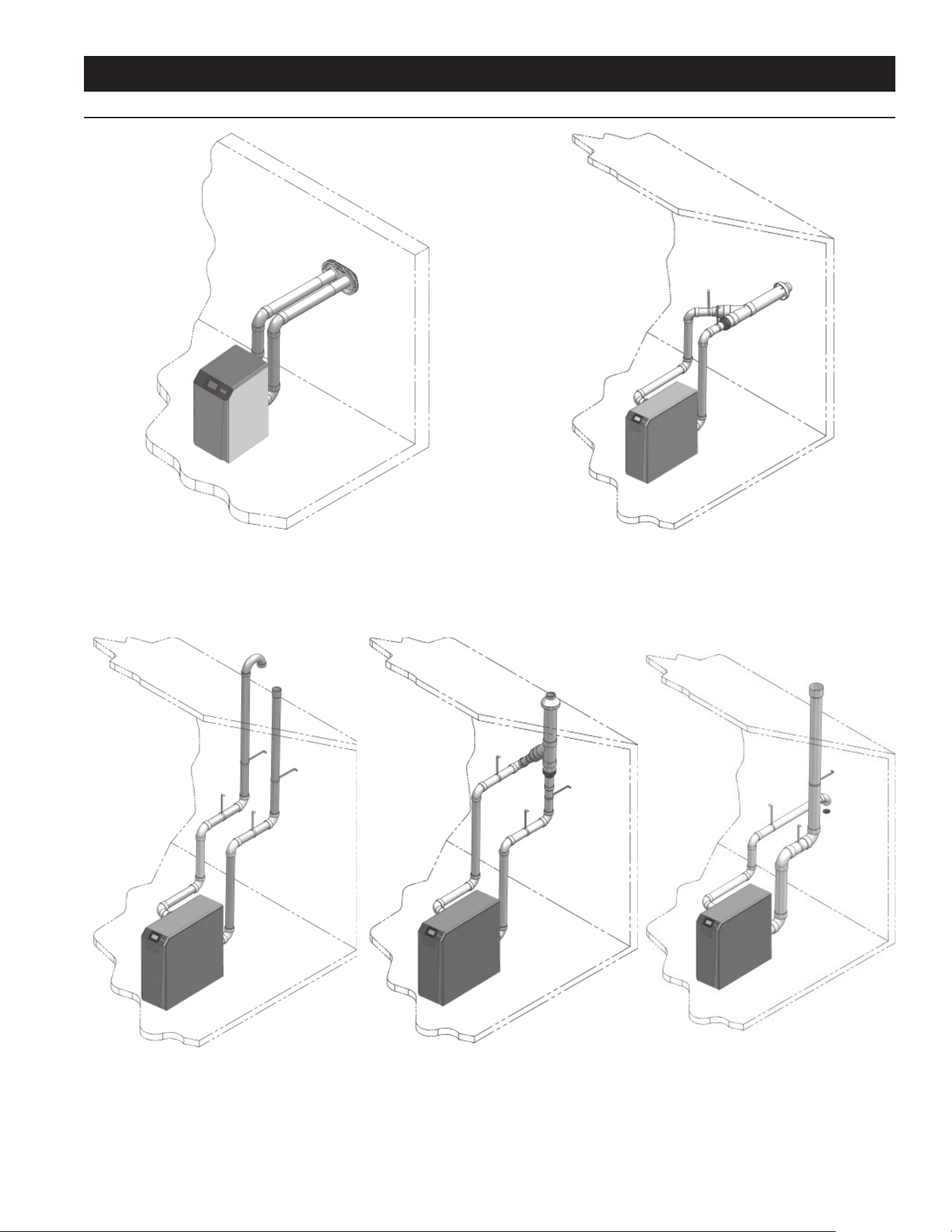
VENTING INSTALLATION
DIRECT VENTING OPTIONS - SIDEWALL VENT
Figure 10. Two-Pipe Sidewall Termination - See page 24 for
more details
Figure 11. PVC/CPVC Concentric Sidewall Termination
(Models 150 - 600 Only) - See Page 28 for more details
Figure 12. Two-Pipe Vertical Termination
- See Page 31 for more details
Figure 13. PVC/CPVC Concentric Vertical
Termination (Models 150 - 600 Only) -
See Page 33 for more details
Figure 14. Vertical Vent, Sidewall Air
18
You may use any of the vent/air piping methods covered in this
manual. Do not attempt to install this water heater using any
other means.
You must also install air piping from outside to the water heater
air intake adapter unless following the Optional Room Air
instructions on Page 20 of this manual. The resultant installation
is direct vent (sealed combustion).
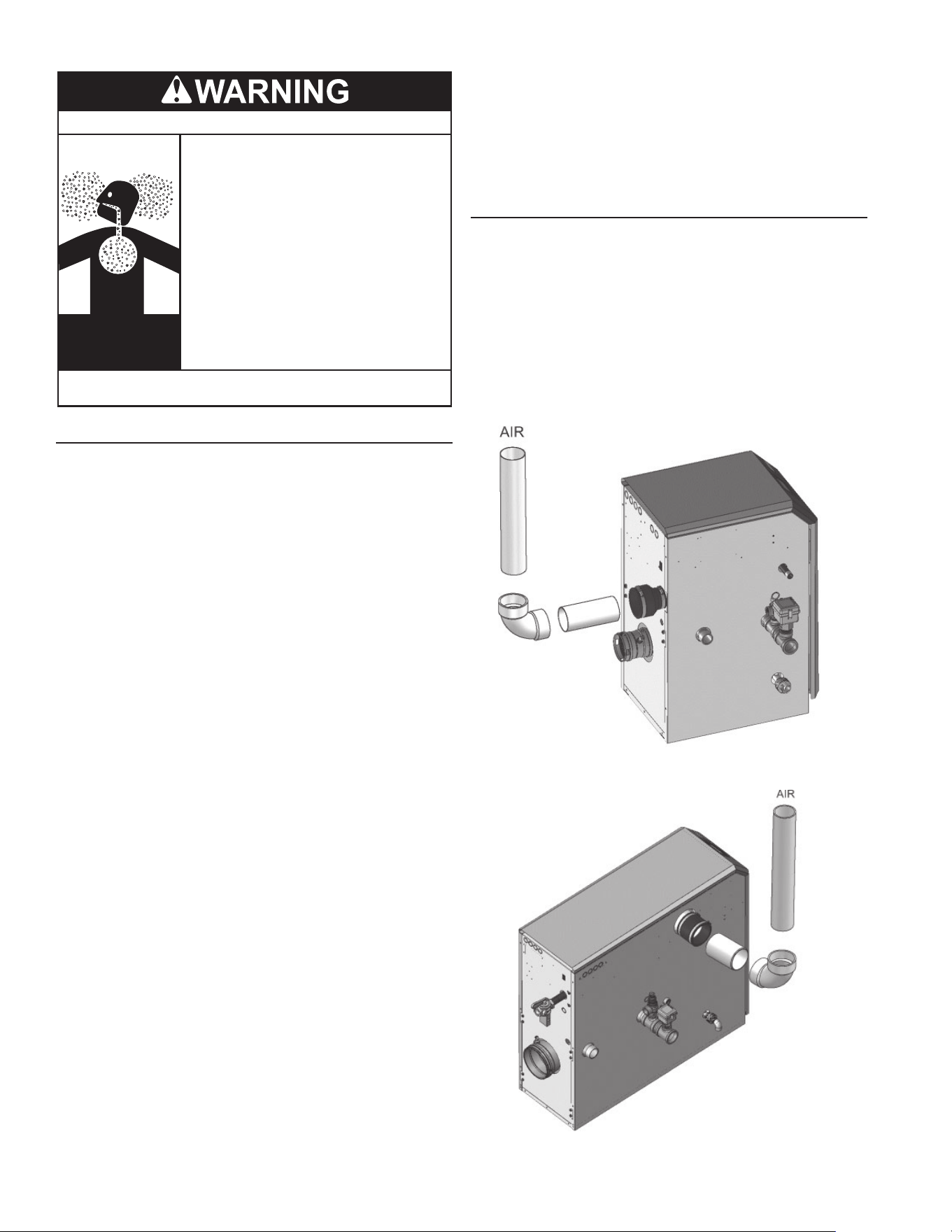
AIR INATKE/ VENT CONNECTIONS
1. Combustion Air Intake Connector (Figures 15 and 16) - Used
to provide combustion air directly to the unit from outdoors. A
fi tting is provided on the unit for fi nal connection. Combustion
air piping must be supported per guidelines listed in the
National Mechanical Code, Section 305, Table 305.4 or as
local codes dictate.
2. Vent Connector (Figure's 17 thru 21) - Used to provide a
passageway for conveying combustion gases to the outside.
A transition fi tting is provided on the unit for fi nal connection.
Vent piping must be supported per the National Building
Code, Section 305, Table 305.4 or as local codes dictate.
Figure 15. Near Water Heater Air Piping Models 150-200
Figure 16. Near Water Heater Air Piping Models 285-600
Breathing carbon monoxide can cause brain damage or death.
Always read and understand the instruction manual.
Install vent system in accordance with codes.
Do not operate water heater if exposed to flooding or
water damage
Special consideration must be taken with installations
above 10,000 feet (3,048 m) refer to high altitude
section of this manual.
Breathing Hazard - Carbon Monoxide Gas
•
•
Do not operate if soot buildup.
•
Do not obstruct water heater air intake with insulating
jacket or blanket.
•
Do not place chemical vapor emitting products near
water heater.
•
Gas and carbon monoxide detectors are available.
•
Never operate the heater unless it is vented to the
outdoors and has adequate air supply to avoid risks
of improper operation, fire, explosion or asphyxiation.
•
Analyze the entire vent system to make sure that
condensate will not become trapped in a section of
vent pipe and therefore reduce the open cross
sectional area of the vent.
•
•
INSTALL VENT AND COMBUSTION AIR PIPING
This water heater must be vented and supplied with combustion
and Category IV ventilation air as described in this section.
Ensure the vent and air piping and the combustion air supply
comply with these instructions regarding vent system, air system,
and combustion air quality.
Inspect fi nished vent and air piping thoroughly to ensure all are
airtight and comply with the instructions provided and with all
requirements of applicable codes. Failure to provide a properly
installed vent and air system will cause severe personal injury
or death.
This appliance requires a special venting system. Use only
approved stainless steel, PVC, CPVC or polypropylene pipe and
fi ttings listed in Tables 11, 12, and 14 for vent pipe, and fi ttings.
Failure to comply could result in severe personal injury, death, or
substantial property damage.
DO NOT mix components from different systems. The vent
system could fail, causing leakage of fl ue products into the living
space. Mixing of venting materials will void the warranty and
certifi cation of the appliance.
Installation must comply with with the National Fuel Gas Code,
ANSI Z223.1/NFPA 54 (Current Edition); CSA B149.1, Natural
Gas and Propane Installation Code (Current Edition); or applicable
provisions of the local building code for U.S. installations.
For closet and alcove installations, CPVC, polypropylene or
stainless steel material MUST BE used in a closet/alcove
structure. Failure to follow this warning could result in fi re,
personal injury, or death.
Improper installation of venting systems may result in injury or
death.
Follow the instructions on Page 14 of this manual when removing
a water heater from an existing vent system.
Do not connect any other appliance to the vent pipe or multiple
water heaters to a common vent pipe. Failure to comply could
result in severe personal injury, death, or substantial property
damage. Do not connect this appliance to a chimney fl ue serving
an appliance designed to burn solid fuel.
This water heater vent and air piping can be installed through the
roof or through a sidewall. Follow the procedures in this manual
for the method chosen. Refer to the information in this manual to
determine acceptable vent and air piping length.
19
NOTE: The use of double-wall vent or insulated material for the
combustion air inlet pipe is recommended in cold climates to
prevent the condensation of airborne moisture in the incoming
combustion air.
Sealing of Type “B” double-wall vent material or galvanized vent
pipe material used for air inlet piping on a sidewall or vertical
rooftop Combustion Air Supply System:
• Seal all joints and seams of the air inlet pipe using either
Aluminum Foil Duct Tape meeting UL Standard 723 or
181A-P or a high quality UL Listed silicone sealant such as
those manufactured by Dow Corning or General Electric.
• Do not install seams of vent pipe on the bottom of horizontal
runs.
• Secure all joints with a minimum of three (3) sheet metal
screws or pop rivets. Apply Aluminum Foil Duct Tape or
silicone sealant to all screws or rivets installed in the vent
pipe.
• Ensure that the air inlet pipes are properly supported.
The PVC, CPVC, or ABS air inlet pipe should be cleaned and
sealed with the pipe manufacturer’s recommended solvents and
standard commercial pipe cement for the material used. The
PVC, CPVC, ABS, Dryer Vent or Flex Duct air inlet pipe should
use a silicone sealant to ensure a proper seal at the appliance
connection and the air inlet cap connection. Dryer vent or fl ex
duct should use a screw type clamp to seal the vent to the
appliance air inlet and the air inlet cap. Proper sealing of the air
inlet pipe ensures that combustion air will be free of contaminants
and supplied in proper volume.
Follow the polypropylene manufacturer’s instructions when using
polypropylene material as an inlet pipe.
When a sidewall or vertical rooftop combustion air supply system
is disconnected for any reason, the air inlet pipe must be resealed
to ensure that combustion air will be free of contaminants and
supplied in proper volume.
Failure to properly seal all joints and seams as required in the
air inlet piping may result in fl ue gas recirculation, spillage of
fl ue products and carbon monoxide emissions causing severe
personal injury or death.
SIZING
This water heater uses model specifi c combustion air intake and
vent piping sizes as detailed in Table below.
Table 8. Air Intake/Vent Piping Sizes
MODEL AIR INTAKE VENT
150 - 200 3 inches 3 inches
285 - 600 4 inches 4 inches
700 - 800 4 inches 6 inches
NOTE: Increasing or decreasing combustion air or vent piping sizes is not
authorized.
MINIMUM/ MAXIMUM ALLOWABLE COMBUSTION AIR
AND VENT PIPING LENGTHS ARE AS FOLLOWS
Combustion Air = 12 equivalent feet minimum / 100 equivalent
feet maximum.
Vent = 12 equivalent feet minimum / 100 equivalent feet
maximum.
NOTE: When using the alternative 3" vent and combustion
air piping with an XWH 285 model, the maximum allowable
combustion air and vent piping lengths are limited to 60 equivalent
feet each. The minimum allowable combustion air and vent pipe
lengths remain 12 equivalent feet each.
When determining equivalent combustion air and vent length,
add 5 feet for each 90° elbow and 3 feet for each 45° elbow.
EXAMPLE: 20 feet of PVC pipe + (4) 90° elbows + (2) 45° elbows
+ (1) concentric vent kit (100274637) = 49 equivalent feet of
piping.
NOTE: The appliance output rating will reduce by up to 1.5% for
each 25 feet of vent length, except when using the alternative 3"
vent for the XWH 285 model which may de-rate by up to 4% for
each 25 feet of vent length.
Table 9. Concentric Vent Kit Equivalent Vent Lengths
MODEL KIT NUMBER EQUIVALENT
VENT LENGTH
150 - 200 100274637 3 feet
285 100274638 3 feet
400 100274638 5 feet
500 - 600 100274638 30 feet
AIR INLET PIPE MATERIALS
The air inlet pipe(s) must be sealed. Choose acceptable
combustion air inlet pipe materials from the following list:
• PVC, CPVC, Polypropylene or ABS
• Galvanized steel vent pipe with joints and seams sealed as
specifi ed in this section.
• Type “B” double-wall vent with joints and seams sealed as
specifi ed in this section.
• AL29-4C, stainless steel material to be sealed to specifi cation
of its manufacturer.
*Plastic pipe may require an adapter (not provided) to transition
between the air inlet connection on the appliance and the plastic
air inlet pipe.
Using air intake materials other than those specifi ed can result in
personal injury, death or property damage.
20
If contaminants are found, you MUST:
• Remove contaminants permanently. —OR—
• Relocate air inlet and vent terminations to other areas.
PVC/ CPVC
This product has been approved for use with the PVC/CPVC
vent materials listed in Table 11.
INSTALLING VENT AND AIR PIPING
The vent connection to the appliance must be made with the
starter CPVC pipe section provided with the appliance if PVC/
CPVC vent is to be used. The fi eld provided vent fi ttings must
be cemented to the CPVC pipe section using an “All Purpose
Cement” suitable for PVC and CPVC pipe. Use only the vent
materials, primer, and cement specifi ed in Table 11 to make the
vent connections. Failure to follow this warning could result in
fi re, personal injury, or death.
Use only cleaners, primers, and solvents that are approved for
the materials which are joined together.
All PVC vent pipes must be glued, properly supported, and the
exhaust must be pitched a minimum of a 1/4 inch per foot back to
the water heater (to allow drainage of condensate).
Insulation should not be used on PVC or CPVC venting materials.
The use of insulation will cause increased vent wall temperatures,
which could result in vent pipe failure.
Table 11. PVC/CPVC Vent Pipe, and Fittings
APPROVED PVC/CPVC VENT PIPE AND FITTINGS
ITEM MATERIAL STANDARD
Vent Pipe
PVC Schedule 40, 80 ANSI/ASTM D1785
PVC - DWV ANSI/ASTM D2665
CPVC Schedule 40, 80 ANSI/ASTM F441
Vent Fittings
PVC Schedule 40 ANSI/ASTM D2466
PVC Schedule 80 ANSI/ASTM D2467
CPVC Schedule 40 ANSI/ASTM F438
CPVC Schedule 80 ANSI/ASTM F439
PVC - DMV ANSI/ASTM D2665
Pipe Cement/
Primer
PVC ANSI/ASTM D2564
CPVC ANSI/ASTM F493
NOTICE: DO NOT USE CELLULAR (FOAM) CORE PIPE
1. Work from the water heater to vent or air termination. Do not
exceed the lengths given in this manual for the air or vent
piping.
2. Cut pipe to the required lengths and deburr the inside and
outside of the pipe ends.
3. Clean all pipe ends and fi ttings using a clean dry rag.
(Moisture will retard curing and dirt or grease will prevent
adhesion.)
4. Chamfer outside of each pipe end to ensure even cement
distribution when joining.
5. Make sure shavings from plastic material are removed to
prevent them from entering the burner.
6. Dry fi t vent or air piping to ensure proper fi t up before
assembling any joint. The pipe should go a third to two-
thirds into the fi tting to ensure proper sealing after cement
is applied.
VENT, AIR PIPING AND TERMINATION
This water heater vent and air piping can be installed through the
roof or through a sidewall. Follow the procedures in this manual
for the method chosen. Refer to the information in this manual to
determine acceptable vent and air piping length.
OPTIONAL ROOM AIR
Optional room air is intended for commercial applications.
Combustion air piping to the outside is recommended for
residential applications.
Commercial applications utilizing this water heater may be
installed with a single pipe carrying the fl ue products to the
outside while using combustion air from the equipment room. In
order to use the room air venting option the following conditions
and considerations must be followed.
• The unit MUST be installed with the appropriate room air kit
(Table 10).
• The equipment room MUST be provided with properly sized
openings to assure adequate combustion air. Refer to the
instructions provided with the room air kit.
• There will be a noticeable increase in the noise level during
normal operation from the inlet air opening.
• Using the room air kit makes the unit vulnerable to combustion
air contamination from within the building. Please review
Prevent Combustion Air Contamination section on Page 13,
to ensure proper installation.
• Vent system and terminations must comply with the standard
venting instructions set forth in this manual.
When utilizing the single pipe method, provisions for combustion
and ventilation air must be in accordance with Air for Combustion
and Ventilation, of the latest edition of the National Fuel Gas
Code, ANSI Z223.1.
Table 10. Optional Room Air Kit
MODEL KIT NUMBER DESCRIPTION
150 - 200 100274659 Room Air Kit
285 - 800 100274661 Room Air Kit
400 - 800 100274662 Room Air Filter Kit
AIR CONTAMINATION
Pool and laundry products and common household and hobby
products often contain fl uorine or chlorine compounds. When
these chemicals pass through the water heater, they can form
strong acids. The acid can eat through the water heater wall,
causing serious damage and presenting a possible threat of fl ue
gas spillage or appliance water leakage into the building.
Please read the information given on Page 14, listing
contaminants and areas likely to contain them. If contaminating
chemicals will be present near the location of the water heater
combustion air inlet, have your installer pipe the water heater
combustion air and vent to another location, per this manual.
If the water heater combustion air inlet is located in a laundry
room or pool facility, for example, these areas will always contain
hazardous contaminants.
To prevent the potential of severe personal injury or death, check
for areas and products listed on Page 14 before installing the
water heater or air inlet piping.
21
7. Priming and Cementing:
• Handle fi ttings and pipes carefully to prevent
contamination of surfaces.
• Apply a liberal even coat of primer to the fi tting socket
and to the pipe end to approximately 1/2" beyond the
socket depth.
• Apply a second primer coat to the fi tting socket.
• While primer is still wet, apply an even coat of approved
cement to the pipe equal to the depth of the fi tting socket
along with an even coat of approved cement to the fi tting
socket.
• Apply a second coat of cement to the pipe.
• While the cement is still wet, insert the pipe into the
fi tting, if possible twist the pipe a 1/4 turn as you insert
it. NOTE: If voids are present, suffi cient cement was not
applied and joint could be defective.
• Wipe excess cement from the joint removing ring or
beads as it will needlessly soften the pipe.
Figure 17. Near Water Heater PVC/CPVC Venting
Models 150-600
Figure 18. Near Water Heater PVC/CPVC Venting
Models 700-800
POLYPROPYLENE
This product has been approved for use with the Polypropylene
vent with the manufacturers listed in Table 12.
All terminations must comply with listed options in this manual
and be a single-wall vent offering.
For support and special connections required, see the
manufacturer’s instructions. All vent is to conform to standard
diameter and equivalent length requirements established.
When determining equivalent combustion air and vent length for
polypropylene single-wall piping:
• 1 foot of Duravent 4 inch single-wall pipe is equivalent to 1.6
feet of piping.
FLEXIBLE POLYPROPYLENE
For use of fl ex pipe, it is recommended to have the vent material
in 32°F or higher ambient space before bending at installation.
No bends should be made to greater than 45° and ONLY installed
in vertical or near vertical installations (Figure 19).
Table 12. Polypropylene Vent Pipe and Fittings
APPROVED POLYPROPYLENE VENT MANUFACTURERS
MAKE MODEL
Centrotherm Eco Systems InnoFlue SW/Flex
Duravent (M & G Group)
PolyPro Single-Wall /
PolyPro Flex
Figure 19. Near Water Heater Flexible Polypropylene
Venting
22
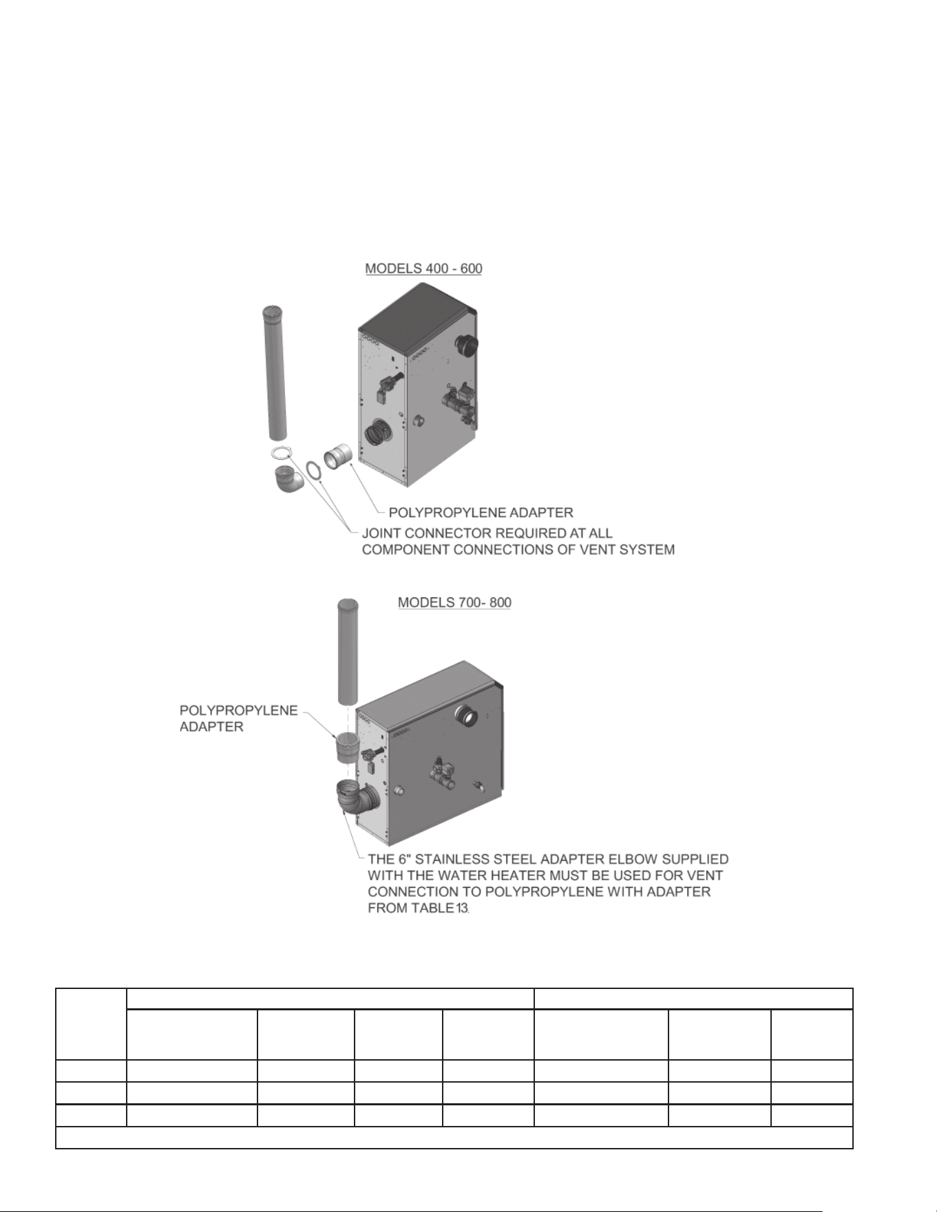
Use only the adapters and vent system listed in Tables 12 and 13.
DO NOT mix vent systems of different types or manufacturers.
Failure to comply could result in severe personal injury, death, or
substantial property damage.
Installations must comply with applicable national, state, and
local codes.
Installation of a polypropylene vent system should adhere to the
vent manufacturer’s installation instructions supplied with the
vent system.
All terminations must comply with listed options in this manual
and be a single-wall vent offering.
The installer must use a specifi c vent starter adapter at the
fl ue collar connection. This adapter is supplied by the vent
manufacturer to adapt to its vent system. See Table 13 for
approved vent adapters. Do not use CPVC starter piece.
All vent connections MUST be secured by the vent manufacturer's
joint connector (Figure 20).
Insulation should not be used on polypropylene venting
materials. The use of insulation will cause increased vent wall
temperatures, which could result in vent pipe failure.
Table 13. Approved PolypropyleneTerminations
MODEL
CENTROTHERM INNOFLUE SW DURAVENT POLYPRO
POLYPROPYLENE
ADAPTER
JOINT
CONNECTOR
SIDEWALL
RETAINING
BRACKET*
SIDEWALL
ADAPTER*
POLYPROPYLENE
ADAPTER
JOINT
CONNECTOR
SIDEWALL
KIT*
150 - 200 ISAAL0303 IANS03 IATP0303 ISTAGL0303 3PPS-AD 3PPS-LB 3PPS-HLK
400 - 600 ISAAL0404 IANS04 IATP0404 ISTAGL0404 4PPS-AD 4PPS-LB 4PPS-HLK
700 - 800 ISAAL0606 Not Required IATP0606 ISTAGL0606 FSA-6PVCM-6PPS Not Required 6PPK-HLK
* These parts are only needed if the sidewall termination assembly is used (see Figure 31 on Page 27).
Figure 20. Near Water Heater Polypropylene Venting
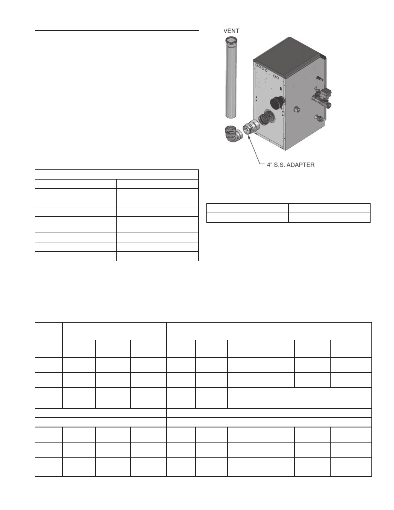
23
STAINLESS STEEL VENT
This product has been approved for use with stainless steel
using the manufacturers listed in Table 14.
Use only the materials, vent systems, and terminations listed in
Tables 14 and 16. DO NOT mix vent systems of different types or
manufacturers. Failure to comply could result in severe personal
injury, death, or substantial property damage.
The installer must use a specifi c vent starter adapter at the fl ue
collar connection, supplied by the vent manufacturer to adapt to
its vent system. See Table 16 for approved vent adapters. Do not
use CPVC starter piece.
Installations must comply with applicable national, state, and
local codes. Stainless steel vent systems must be listed as a UL-
1738 approved system for the United States.
Installation of a stainless steel vent system should adhere to
the stainless steel vent manufacturer’s installation instructions
supplied with the vent system.
Table 14. Stainless Steel Vent Pipe and Fittings
APPROVED STAINLESS STEEL VENT MANUFACTURERS
MAKE MODEL
Dura Vent (M & G Group)
FasNSeal Vent /
FasNSeal Flex* Vent
Z-Flex (Nova Flex Group) Z-Vent
Heat Fab (Selkirk
Corporation)
Saf-T Vent
Metal Fab Corr/Guard
Security Chimney Secure Seal
ICC VIC
*Use of FasNSeal Flex smooth inner wall vent is to be used in
vertical or near vertical sections only, taking precaution to ensure
no sagging occurs of the vent system. Connect to the FasNSeal
rigid vent using specially designed adapters and sealing method,
see manufacturer’s instructions.
Figure 21. Near Water Heater Stainless Steel Venting
Models 285 - 600
Table 15. Stainless Steel Sidewall Vent Termination Kit(s)
MODEL KIT NUMBER
700 - 800 100274668
Table 16. Approved Stainless Steel (S.S) Terminations and Adapters
MODEL PROTECH HEAT FAB Z FLEX
FASNSEAL SAF-T VENT Z-VENT
S.S Adapter
Flue
Termination
Intake Air
Termination
S.S.
Adapter
Flue
Termination
Intake Air
Termination
S.S.
Adapter
Flue
Termination
Intake Air
Termination
150 - 200
300715 FSBS3
FSRC3
303889 9301PVC 9392
5300CI
9314TERM 2SVSLA03 2SVSTP03
2SVSRCX03
2SVSTEX0390
400 - 600
F303759 FSBS4
FSRC4
FSAIH04
303888
9401PVC 9492
5400CI
9414TERM 2SVSLA04 2SVSTP04
2SVSRCX04
2SVSTEX0490
700 - 800
F303759
(Intake
Only)
FSBS6 FSAIH04
303888
9601MAD 9690
9692
9614TERM
METAL FAB SECURITY CHIMNEY ICC
Corr/Guard Secure Seal VIC
150 - 200
3CGPVCA 3CGSWHT
3CGSWC
3CGSW90LT -- -- -- -- -- --
400 - 600
4CGPVCA 4CGSWHT
4CGSWC
4CGSW90LT SS4PVCU SS4STU
SS4RCBU
SS4ST90AU -- -- --
700 - 800
6FCGPVCA 6FCGSWMC
6FCGSWC
6FCGSW90L SS6PVCU SS6STU
SS6RCBU
SS6ST90AU HE-6DSA-F HE-6MC-F
HE-6RC-F
HE-6E90-F
HE-6SCR-F
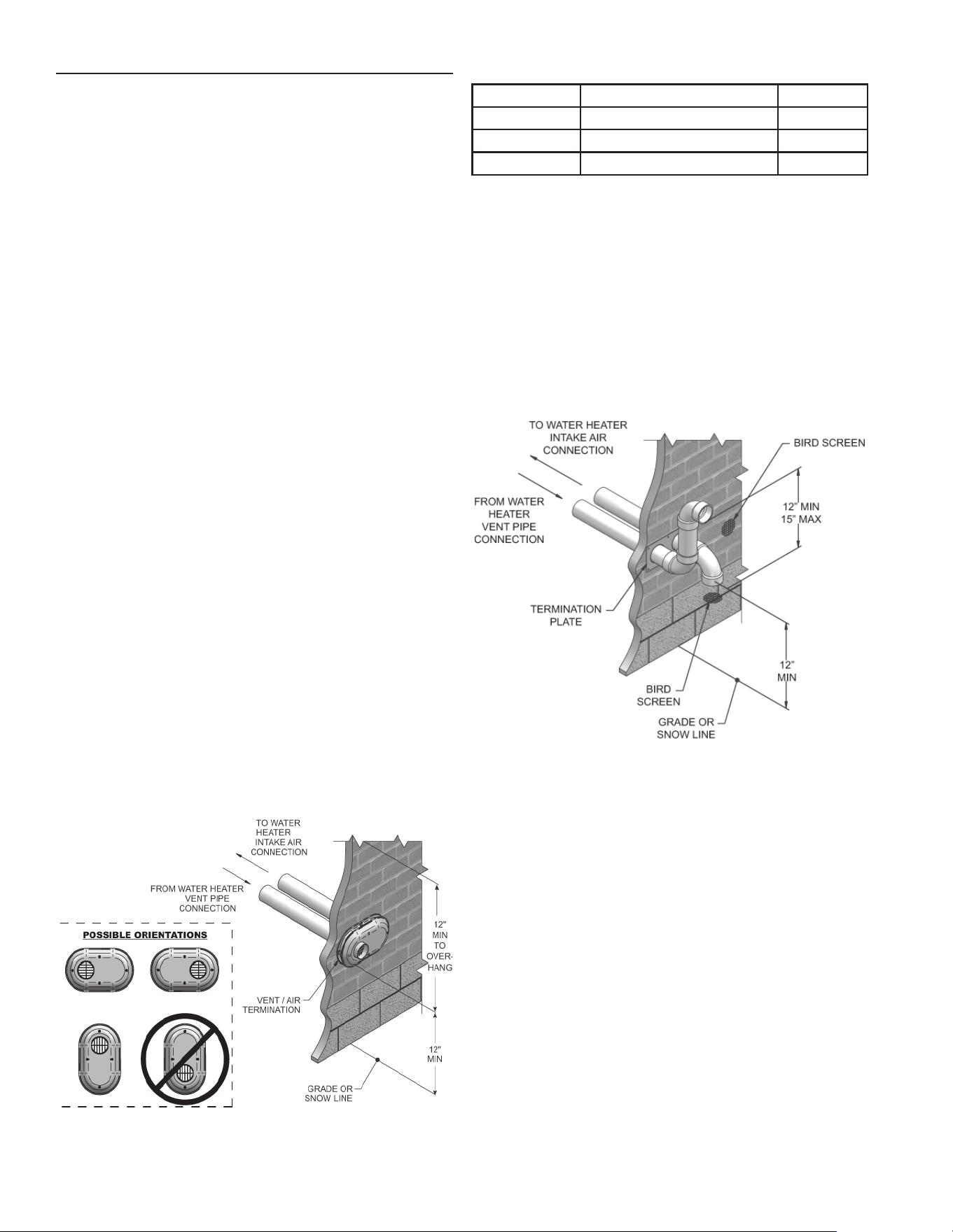
24
If using the alternate sidewall termination:
3. The air piping must terminate in a down-turned elbow as
shown in Figure 23. This arrangement avoids recirculation of
fl ue products into the combustion air stream.
4. The vent piping must terminate in an elbow pointed outward
or away from the air inlet, as shown in Figure 23.
Do not exceed the maximum lengths of the outside vent piping
shown in Figure 23. Excessive length exposed to the outside
could cause freezing of condensate in the vent pipe, resulting in
potential water heater shutdown.
VENT/ AIR TERMINATION - SIDEWALL
Follow instructions below when determining vent location to
avoid possibility of severe personal injury, death, or substantial
property damage.
A exhaust vent extending through an exterior wall shall not
terminate adjacent to a wall or below building extensions such
as eaves, parapets, balconies, or decks. Failure to comply could
result in severe personal injury, death, or substantial property
damage.
DETERMINE LOCATION
Locate the vent/air terminations using the following guidelines:
1. The total length of piping for vent or air must not exceed the
limits given on Table 9 of this manual.
2. You must consider the surroundings when terminating the
vent and air:
a. Position the vent termination where vapors will not
damage nearby shrubs, plants or air conditioning equipment
or be objectionable.
b. The fl ue products will form a noticeable plume as they
condense in cold air. Avoid areas where the plume could
obstruct window views.
c. Prevailing winds could cause freezing of condensate
and water/ice buildup where fl ue products impinge on
building surfaces or plants.
d. Avoid possibility of accidental contact of fl ue products
with people or pets.
e. Do not locate the terminations where wind eddies could
affect performance or cause recirculation, such as inside
building corners, near adjacent buildings or surfaces, window
wells, stairwells, alcoves, courtyards, or other recessed
areas.
Sidewall vent and air inlet terminations must terminate in the
same pressure zone.
f. Do not terminate above any door or window. Condensate
can freeze, causing ice formations.
g. Locate or guard vent to prevent condensate damage to
exterior fi nishes.
Figure 22. PVC/CPVC/Polypropylene Sidewall Termination
of Air and Vent
Table 17. Sidewall Vent Kits
MODEL KIT NUMBER VENT SIZE
150 - 200 100274669 3 inch vent
285 - 600 100274670 4 inch vent
700 - 800 100274671 6 inch vent
Figure 23. Alternate PVC/CPVC Sidewall Termination of Air
and Vent w/Field Supplied Fittings
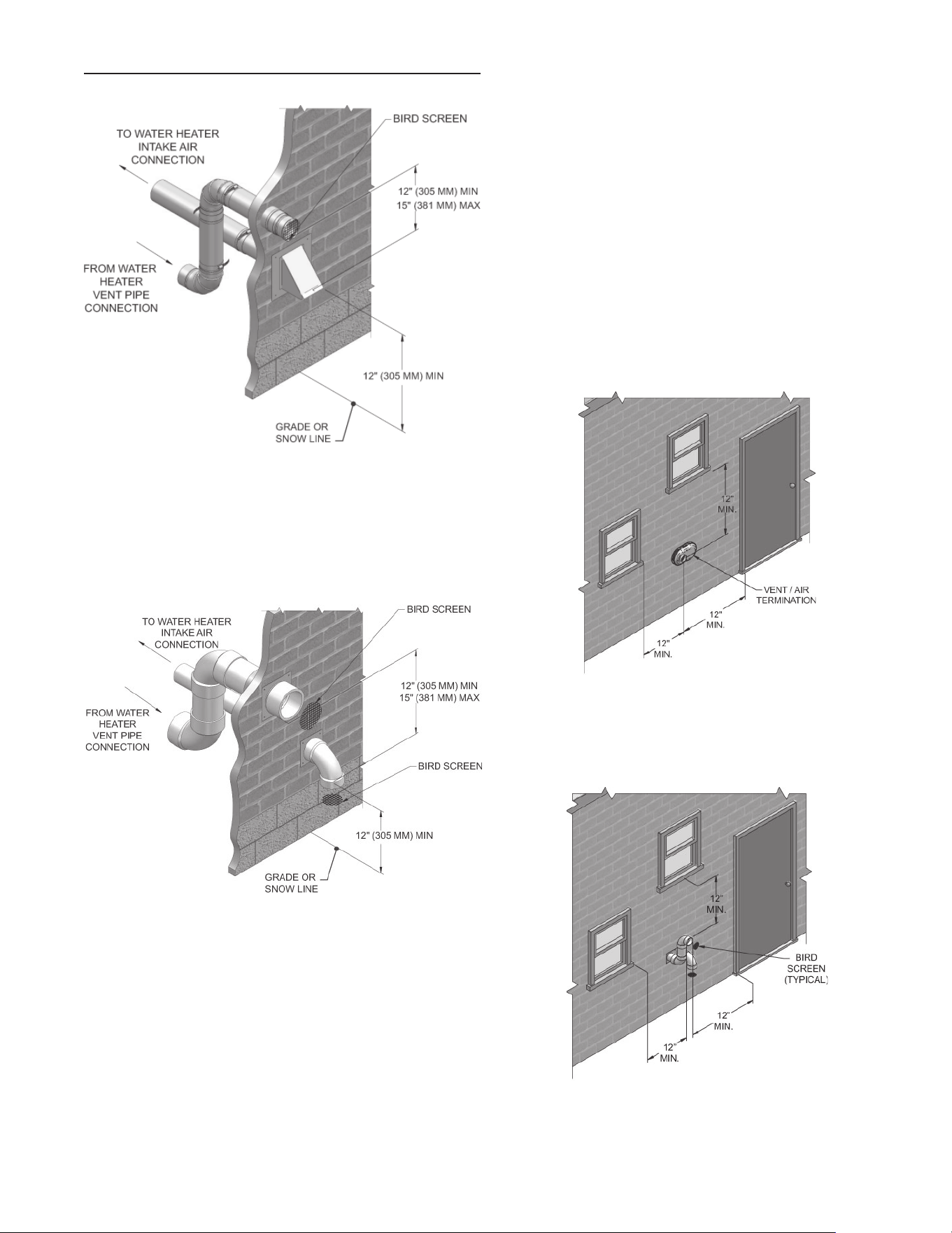
25
5. Maintain clearances as shown in Figure’s 22 thru 27, pages
24 and 25. Also maintain the following:
a. Vent must terminate:
• At least 6 feet from adjacent walls.
• No closer than 12 inches below roof overhang.
b. Air inlet must terminate at least 12 inches above grade
or snow line; at least 12 inches below the vent termination;
and the vent pipe must not extend more than 24 inches
vertically outside the building as shown in Figure 23:
c. Do not terminate closer than 4 feet horizontally from
any electric meter, gas meter, regulator, T & P Relief Valve,
or other equipment. Never terminate above or below any of
these within 4 feet horizontally.
6. Locate terminations so they are not likely to be damaged by
foreign objects, such as stones or balls, or subject to buildup
of leaves or sediment.
VENT/ AIR TERMINATION - SIDEWALL
NOTE: PVC/CPVC or ABS is acceptable air inlet pipe material.
Figure 24. Alternate PVC/CPVC/SS Vent Termination -
Typical Stainless Steel Sidewall Termination of Air and
Vent Models 150 - 800 w/Field Supplied Fittings
Figure 25. Alternate PVC/CPVC/SS/ Polypropylene Sidewall
Termination Models 150 - 800 w/Field Supplied Fittings
Figure 26. Clearance to Gravity Air Inlets
Figure 27. Alternate Clearance to Gravity Air Inlets w/Field
Supplied Fittings
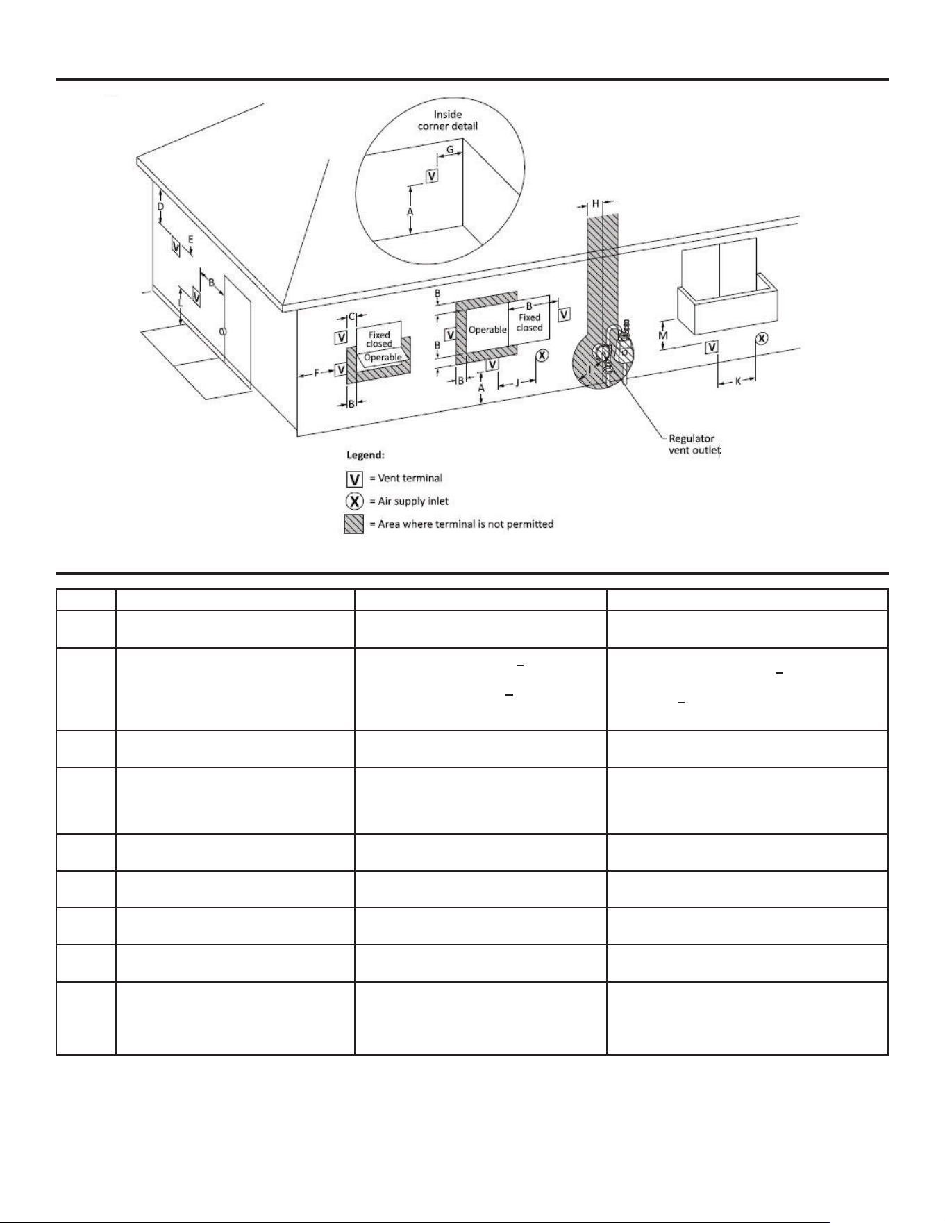
Figure 28. Direct Vent Terminal Clearances
Canadian Installations¹ US Installations²
A =
Clearance above grade, veranda, porch,
deck, or balcony
12 in (30 cm) 12 in (30 cm)
B =
Clearance to window or door that may
be opened
6 in (15 cm) for appliances < 10,000 Btuh
(3 kW), 12 in (30 cm) for appliances >
10,000 Btuh (3 kW) and < 100,000 Btuh
(30 kW), 36 in (91 cm) for appliances >
100,000 Btuh (30 kW)
6 in (15 cm) for appliances < 10,000 Btuh (3
kW), 9 in (23 cm) for appliances > 10,000 Btuh
(3 kW) and < 50,000 Btuh (15 kW), 12 in (30 cm)
for appliances > 50,000 Btuh (15 kW)
C = Clearance to permanently closed window
*
*
D =
Vertical clearance to ventilated sof-
fit located above the terminal within a
horizontal distance of 2 ft (61 cm) from
the center line of the terminal.
*
*
E = Clearance to unventilated soffit
*
*
F = Clearance to outside corner
*
*
G = Clearance to inside corner
*
*
H =
Clearance to each side of center line ex-
tended above meter / regulator assembly
*
*
I = Clearance to service regulator vent outlet
Above a regulator within 3 ft (91 cm)
horizontally of the vertical center line of the
regulator vent outlet to a maximum vertical
distance of 15 ft (4.5 m)
*
Table 18. Direct Vent Terminal Clearances
26
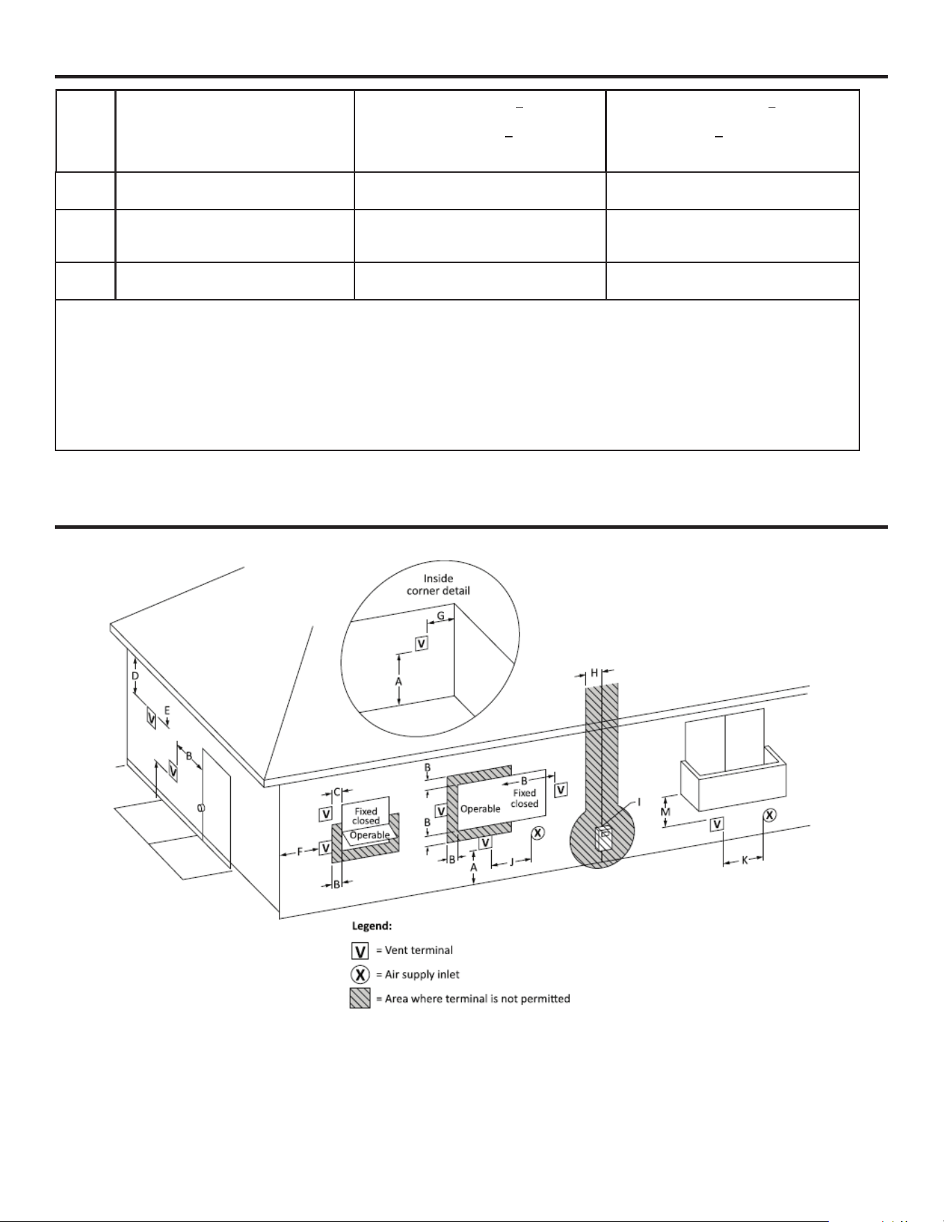
K =
Clearance to a mechanical air supply
inlet
6 ft (1.83 m)
3 ft (91 cm) above if within 10 ft (3 m)
horizontally
L =
Clearance above paved sidewalk or
paved driveway located on public prop-
erty
7 ft (2.13 m)† *
M =
Clearance under veranda, porch, deck,
or balcony
12 in (30 cm)‡ *
* Clearance in accordance with local installation codes and the requirements of the gas supplier.
† A vent shall not terminate directly above a sidewalk or paved driveway that is located between two single family dwellings
and serves both dwellings.
‡ Permitted only if veranda, porch, deck, or balcony is fully open on a minimum of two sides beneath he oor.
NOTES:
1) In accordance with the current CSA B149.1, Natural Gas and Propane Installation Code
2) In accordance with the current ANSI Z223.1/NFPA 54, National Fuel Gas Code
Table 18. Direct Vent Terminal Clearances (continued)
Figure 29. Other than Direct Vent Terminal Clearances
J =
Clearance to nonmechanical air supply
inlet to building or the combustion air
inlet to any other appliance
6 in (15 cm) for appliances < 10,000 Btuh
(3kW), 12 in (30 cm) for appliances >
10,000 Btuh (3 kW) and < 100,000 Btuh
(30 kW), 36 in (91 cm) for appliances >
100,000 Btuh (30 kW)
6 in (15 cm) for appliances < 10,000 Btuh
(3kW), 9 in (23 cm) for appliances > 10,000
Btuh (3 kW) and < 50,000 Btuh (15 kW),
12 in (30 cm) for appliances > 50,000 Btuh
(15 kW)
27
Canadian Installations¹ US Installations²
A =
Clearance above grade, veranda, porch,
deck, or balcony
12 in (30 cm) 12 in (30 cm)
B =
Clearance to window or door that may
be opened
6 in (15 cm) for appliances < 10,000 Btuh
(3 kW), 12 in (30 cm) for appliances >
10,000 Btuh (3 kW) and < 100,000 Btuh
(30 kW), 36 in (91 cm) for appliances >
100,000 Btuh (30 kW)
4 ft (1.2 m) below or to side of opening; 1 ft (300
mm) above opening
C = Clearance to permanently closed window
**
D =
Vertical clearance to ventilated sof-
fit located above the terminal within a
horizontal distance of 2 ft (61 cm) from
the center line of the terminal.
**
E = Clearance to unventilated soffit
**
F = Clearance to outside corner
**
G = Clearance to inside corner
**
H =
Clearance to each side of center line ex-
tended above meter / regulator assembly
**
I = Clearance to service regulator vent outlet
Above a regulator within 3 ft (91 cm)
horizontally of the vertical center line of the
regulator vent outlet to a maximum vertical
distance of 15 ft (4.5 m)
*
J =
Clearance to nonmechanical air supply
inlet to building or the combustion air
inlet to any other appliance
6 in (15 cm) for appliances < 10,000 Btuh
(3kW), 12 in (30 cm) for appliances >
10,000 Btuh (3 kW) and < 100,000 Btuh
(30 kW), 36 in (91 cm) for appliances >
100,000 Btuh (30 kW)
4 ft (1.2 m) below or to side of opening; 1 ft (300
mm) above opening
K =
Clearance to a mechanical air supply
inlet
6 ft (1.83 m) 3 ft (91 cm) above if within 10 ft (3 m) horizon-
tally
L =
Clearance above paved sidewalk or
paved driveway located on public prop-
erty
7 ft (2.13 m)† 7 ft (2.13 m)
M =
Clearance under veranda, porch, deck,
or balcony
12 in (30 cm)‡ *
* Clearance in accordance with local installation codes and the requirements of the gas supplier.
† A vent shall not terminate directly above a sidewalk or paved driveway that is located between two single family dwellings
and serves both dwellings.
‡ Permitted only if veranda, porch, deck, or balcony is fully open on a minimum of two sides beneath he oor.
NOTES:
1) In accordance with the current CSA B149.1, Natural Gas and Propane Installation Code
2) In accordance with the current ANSI Z223.1/NFPA 54, National Fuel Gas Code
Table 19. Other than Direct Vent Terminal Clearances
28
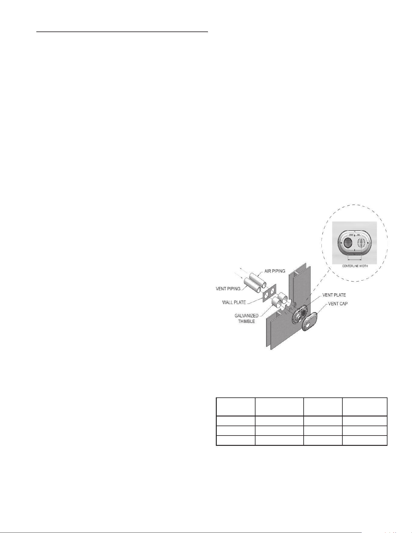
29
2. For Polypropylene Only: Install the vent and air intake
sidewall adapters from Table 13 on Page 22 into the vent
plate. Slide the sidewall retaining bracket down the sidewall
adapters fl ush to the vent plate.
3. For PVC/CPVC Only: Install the vent and air intake piping
through the wall into the vent plate openings. Use RTV
silicone sealant to seal the air pipe. Use the cement/primer
listed in Table 11 on Page 20 to seal the vent pipe.
4. Mount and secure the vent plate to the wall using stainless
steel screws. Seal around the plate to the wall assuring no
air gaps.
5. Seal all gaps between the pipes and wall. Seal around the
plate to the wall assuring no air gaps.
6. Assemble the vent cap to the vent plate (see Figure 30).
Insert the stainless steel screws into the vent cap screw hole
openings and securely attach the vent cap to the vent plate.
7. Seal all wall cavities.
8. PVC/CPVC terminations are designed to accommodate any
wall thickness of standard constructions per the directions
found in this manual.
9. Stainless steel terminations are designed to penetrate walls
with a thickness up to 9.25 inches of standard construction.
SIDEWALL DIRECT VENTING
PREPARE WALL PENETRATIONS
1. Use the factory supplied wall plate as a template to locate the
vent and air intake holes and mounting holes.
Air pipe penetration:
a. Cut a hole for the air pipe. Size the air pipe hole as close
as desired to the air pipe outside diameter.
Vent pipe penetration:
a. Cut a hole for the vent pipe. For either combustible or
noncombustible construction, size the vent pipe hole with
at least a 1/2 inch clearance around the vent pipe outer
diameter:
• 4½ inch hole for 3 inch vent pipe.
• 5½ inch hole for 4 inch vent pipe.
• 7½ inch hole (191 mm) hole for 6 inch (152 mm) vent
pipe
Drill 3/16” diameter holes for inserting the plastic anchors into
the wall.
Figure 30. Sidewall Termination Assembly
Table 18. Sidewall Vent Centerline Dimensions
MODEL AIR VENT CENTERLINE
WIDTH
150 - 200 3" 3" 5 5/8"
285 - 600 4" 4" 5 5/8"
700 - 800 4" 6" 7 3/4"
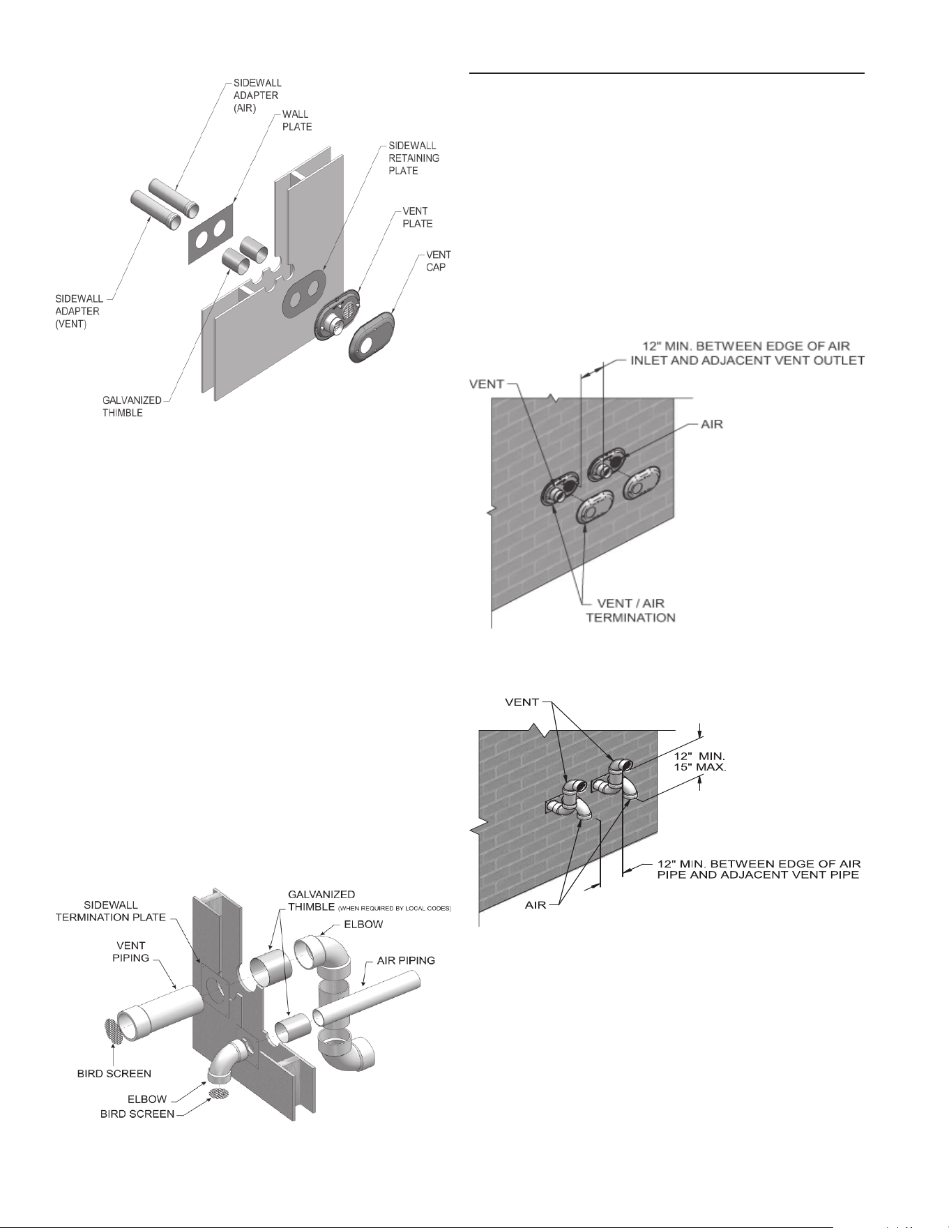
30
PREPARE WALL PENETRATIONS (ALTERNATE - FIELD
SUPPLIED OPTION)
1. Air pipe penetration:
a. Cut a hole for the air pipe. Size the air pipe hole as close
as desired to the air pipe outside diameter.
2. Vent pipe penetration:
a. Cut a hole for the vent pipe. For either combustible or
noncombustible construction, size the vent pipe hole with
at least a 1/2 inch clearance around the vent pipe outer
diameter:
• 4½ inch hole for 3 inch vent pipe.
• 5½ inch hole for 4 inch vent pipe.
• 7½ inch hole (191 mm) hole for 6 inch (152 mm) vent
pipe.
a. Insert a galvanized metal thimble in the vent pipe hole as
shown in Figure 32.
3. Use a sidewall termination plate as a template for correct
location of hole centers.
4. Follow all local codes for isolation of vent pipe when passing
through fl oors or walls.
5. Seal exterior openings thoroughly with exterior caulk.
Figure 31. Polypropylene Sidewall Termination Assembly
Figure 32. A Typical Sidewall Termination Assembly -
Models 150 - 800 PVC/CPVC or Stainless Steel
MULTIPLE VENT/ AIR TERMINATIONS
1. When terminating multiple XP water heaters terminate each
vent/air connection as described in this manual (Figure 33).
All vent pipes and air inlets must terminate at the same height to
avoid possibility of severe personal injury, death, or substantial
property damage.
2. Place wall penetrations to obtain minimum clearance of 12
inches between edge of air inlet and adjacent vent outlet, as
shown in Figure 33 for U.S. installations.
3. The air inlet of a XP water heater is part of a direct vent
connection. It is not classifi ed as a forced air intake with
regard to spacing from adjacent water heater vents.
Figure 33. Multiple Vent Terminations (must also comply
with Figure 22)
Figure 34. Alternate Multiple Vent Terminations w/Field
Supplied Fittings (must also comply with Figure 23)
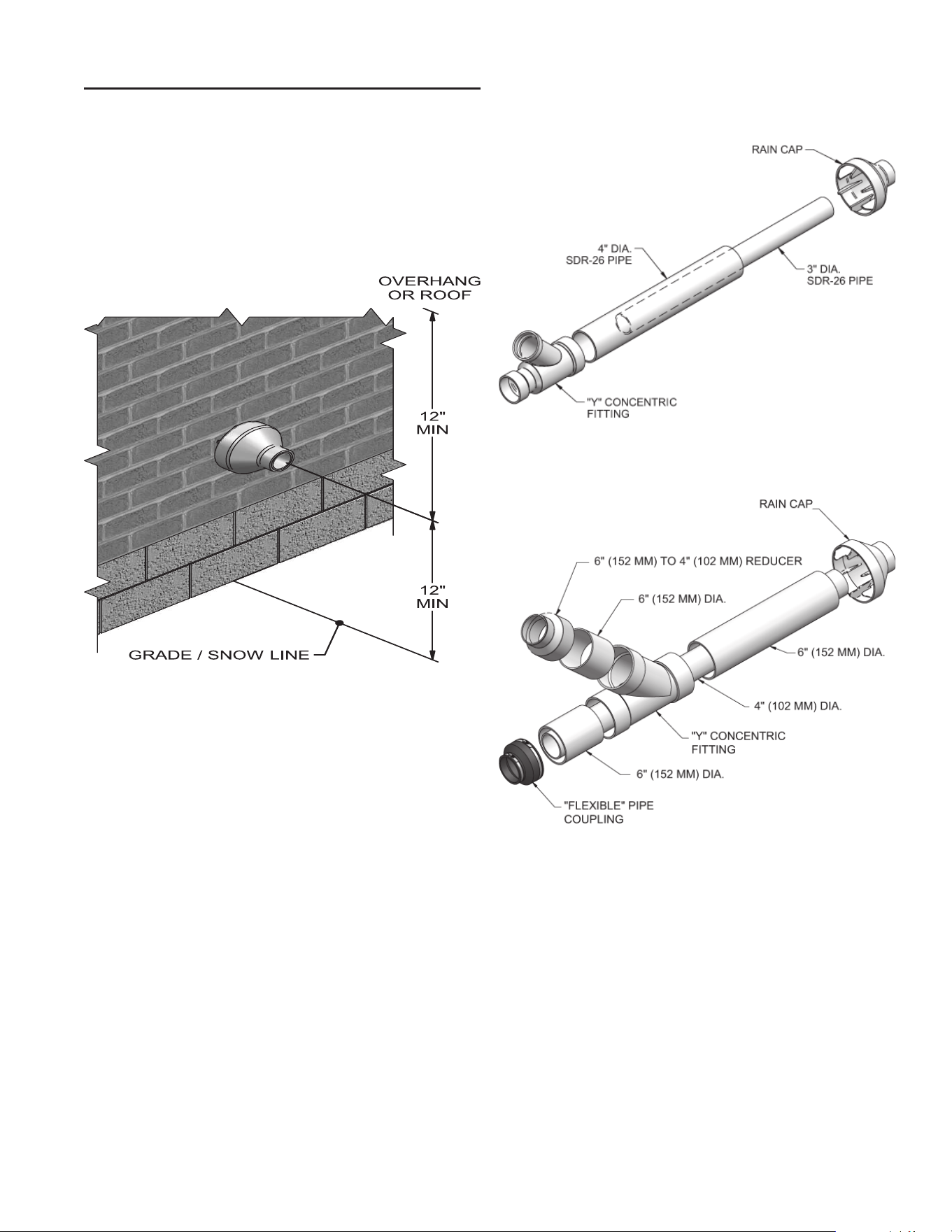
31
SIDEWALL TERMINATION – OPTIONAL CONCENTRIC
VENT: MODELS 150 - 600
DESCRIPTION AND USAGE
A. O. Smith offers optional concentric combustion air and vent
pipe termination kits (Factory Kit #100274637 for 3” diameter -
Models 150 - 200 and #100274638 for 4” diameter - Models 285
- 600). Both combustion air and vent pipes must attach to the
termination kit. The termination kits must terminate outside the
structure and must be installed as shown below in Figure 35.
The required combustion vent pipe materials are listed in Table
11, on Page 20 of this manual.
PREPARE WALL PENETRATIONS
1. Determine the best location for the termination kit (see Figure
above).
2. Reference the Determine Location section on Page 24 of this
manual for general termination considerations.
3. Cut one (1) hole (5 inch diameter for #100274637 installations
or 7 inch diameter for #100274638 installations) into the
structure to install the termination kit.
4. Partially assemble the concentric vent termination kit. Clean
and cement using the procedures found in these instructions.
a. Cement the Y concentric fi tting to the larger kit pipe
(Figure’s 36 and 37).
b. Cement the rain cap to the smaller diameter kit pipe
(Figure’s 36 and 37).
Figure 35. Concentric Sidewall Termination
Figure 36. Kit Contents_100274637 - Models 150 - 200
Figure 37. Kit Contents_100274638 - Models 285 - 600
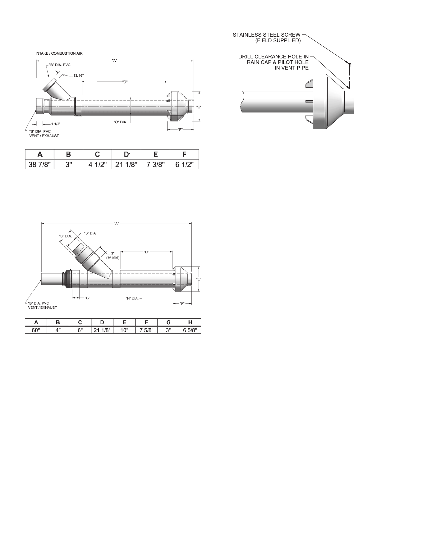
32
5. Install the Y concentric fi tting and pipe assembly through the
structure’s hole.
NOTE: Do not allow insulation or other materials to accumulate
inside the pipe assembly when installing through the hole.
6. Install the rain cap and small diameter pipe assembly into the
Y concentric fi tting and large pipe assembly. Ensure small
diameter pipe is bottomed and cemented in the Y concentric
fi tting for #100274637 installations and fastened tightly into
the rubber adapter for #100274638 installations.
7. Secure the assembly to the structure as shown in Figure 41
using fi eld-supplied metal strapping or equivalent support
material.
NOTE: Ensure termination location clearance dimensions are as
shown in Figure 35.
If assembly needs to be extended to allow sidewall thickness
requirement, the two (2) pipes supplied in the kit may be
replaced by using the same diameter, fi eld-supplied SDR-26
PVC (D2241) pipe for 100274637 and standard schedule 40
PVC for 100274638. Do not extend dimension D* more than 60
inches (see Figures 38 and 39).
If assembly depth needs to be reduced, dimension D can be as
short as possible.
Figure 38. Concentric Vent Dimensional Drawing -
Models 150 - 200
NOTE: Instead of cementing the smaller pipe to the rain cap, a
fi eld-supplied stainless steel screw may be used to secure the
two (2) components together when fi eld disassembly is desired
for cleaning (see Figure 40).
When using the alternate screw assembly method, drill a
clearance hole in the rain cap and a pilot hole in the vent pipe
for the screw size being used. Failure to drill adequate holes
may cause cracking of PVC components, allowing combustion
products to be recirculated. Failure to follow this warning could
result in personal injury or death.
Do not operate the appliance with the rain cap removed or
recirculation of combustion products may occur. Water may
also collect inside the larger combustion air pipe and fl ow to the
burner enclosure. Failure to follow this warning could result in
product damage or improper operation, personal injury, or death.
Figure 39. Concentric Vent Dimensional Drawing -
Models 285 - 500
Figure 40. Rain Cap to Vent Pipe Alternate Assembly
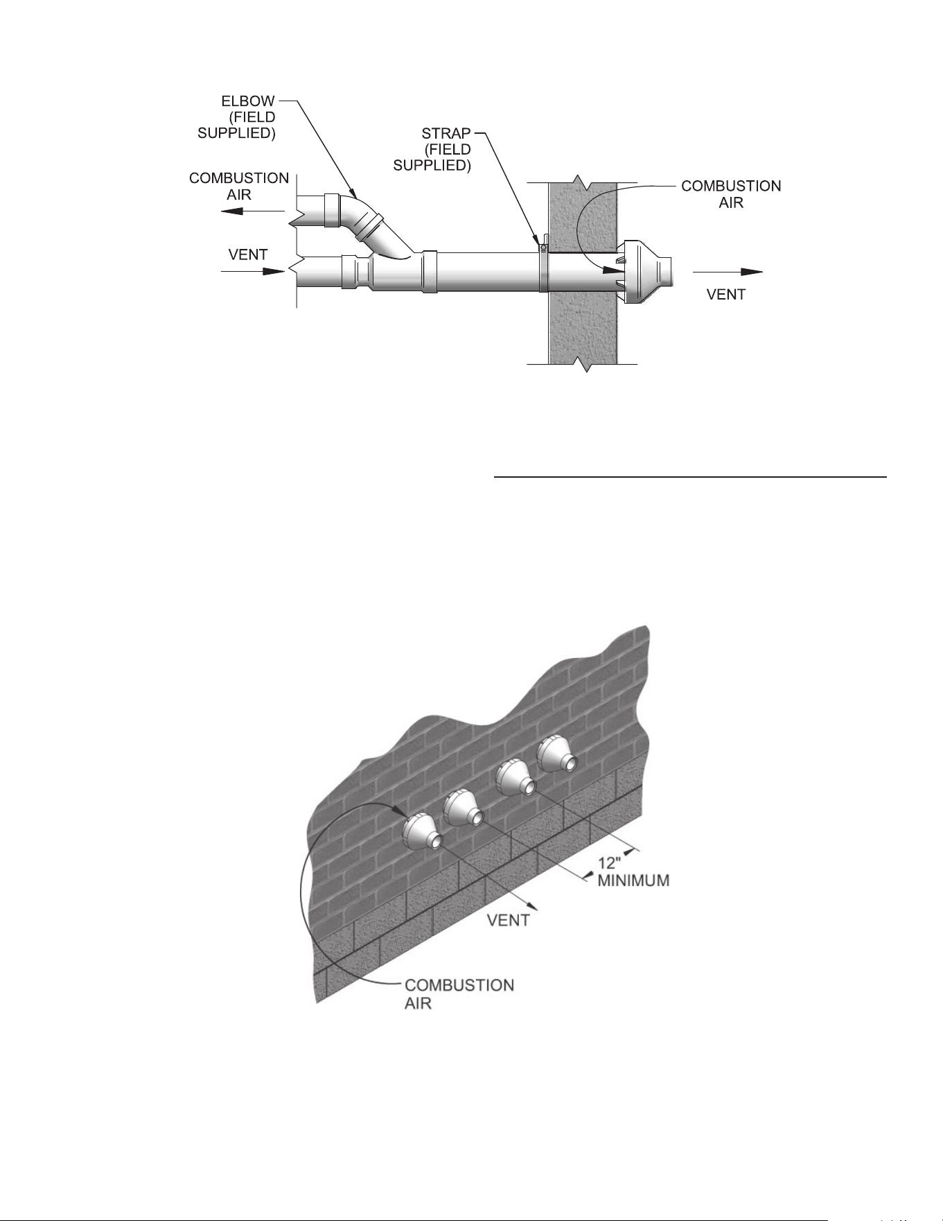
33
MULTIVENTING SIDEWALL TERMINATIONS
When two (2) or more direct vent appliances are vented near
each other, each appliance must be individually vented (see
Figure 42). NEVER common vent or breach vent this appliance.
When two (2) or more direct vent appliances are vented near
each other, two (2) vent terminations may be installed as shown
in Figure 42. It is important that vent terminations be made as
shown to avoid recirculation of fl ue gases.
DO NOT use fi eld-supplied couplings to extend pipes. Airfl ow
restriction will occur and may cause intermittent operation.
8. Cement appliance combustion air and vent pipes to the
concentric vent termination assembly. See Figure 41 for
proper pipe attachment.
9. Operate the appliance one (1) heat cycle to ensure
combustion air and vent pipes are properly connected to the
concentric vent termination connections.
Figure 41. Concentric Vent Sidewall Attachment
Figure 42. Concentric Vent and Combustion Air Termination
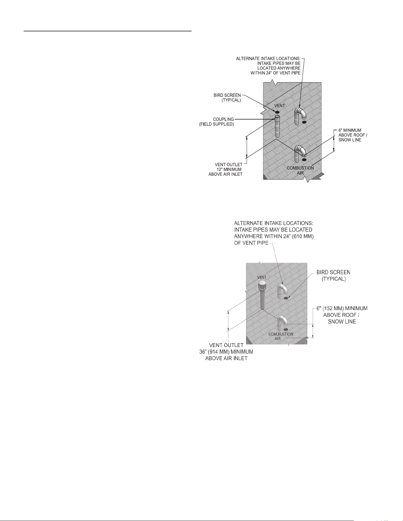
34
VERTICAL DIRECT VENTING
VENT/ AIR TERMINATION - VERTICAL
Follow instructions below when determining vent location to
avoid possibility of severe personal injury, death or substantial
property damage.
DETERMINE LOCATION
Locate the vent/air terminations using the following guidelines:
1. The total length of piping for vent or air must not exceed the
limits given on Table 9 of this manual.
2. Prepare the vent termination and the air termination elbow
(Figure 43) by inserting bird screens. Bird screens should be
obtained locally.
3. The vent must terminate at least 3 feet above the highest
place in which the vent penetrates the roof and at least 2 feet
above any part of a building within 10 horizontal feet.
4. The air piping must terminate in a down-turned 180° return
pipe no further than 2 feet from the center of the vent pipe.
This placement avoids recirculation of fl ue products into the
combustion air stream.
5. The vent piping must terminate in an up-turned coupling as
shown in Figure 43. The top of the coupling must be at least
1 foot above the air intake. When the vent termination uses
a rain cap as illustrated in Figure 44 maintain at least 36”
(914 mm) above the air inlet. The air inlet pipe and vent pipe
can be located in any desired position on the roof, but must
always be no further than 2 feet (.6 m) apart and with the vent
termination at least 1 foot for PVC and 3 feet for stainless
steel, above the air intake.
6. Maintain the required dimensions of the fi nished termination
piping as shown in Figure 43.
7. Do not extend exposed vent pipe outside of building more
than shown in this document. Condensate could freeze and
block vent pipe.
Rooftop vent and air inlet terminations must terminate in the
same pressure zone, unless vertical vent sidewall air is set up as
shown in the Vertical Vent, Sidewall Air section.
8. Locate terminations so they are not likely to be damaged by
foreign objects, such as stones or balls, or subject to buildup
of leaves or sediment.
Figure 43. PVC/CPVC Vertical Termination of Air and Vent
Figure 44. Stainless Steel Vertical Termination of Air and
Vent
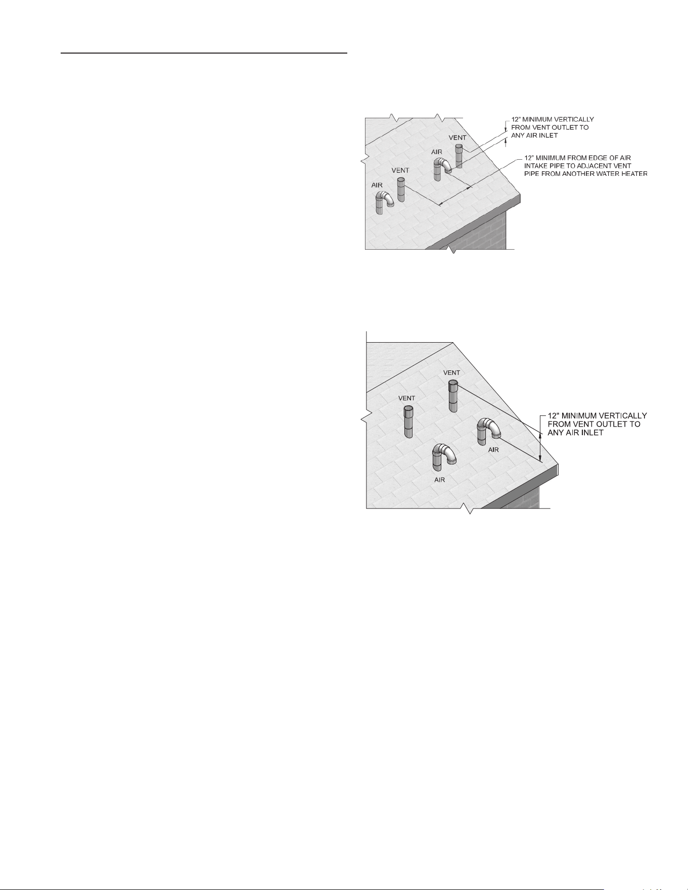
35
PREPARE ROOF PENETRATIONS
1. Air pipe penetration:
a. Cut a hole for the air pipe. Size the air pipe hole as close
as desired to the air pipe outside diameter.
2. Vent pipe penetration:
a. Cut a hole for the vent pipe. For either combustible or
noncombustible construction, size the vent pipe hole with
at least a 1/2 inch clearance around the vent pipe outer
diameter:
• 4½ inch hole for 3 inch vent pipe.
• 5½ inch hole for 4 inch vent pipe.
• 7½ inch hole for 6 inch vent pipe.
b. Insert a galvanized metal thimble in the vent pipe hole.
3. Space the air and vent holes to provide the minimum spacing
shown in Figure 43 on Page 31.
4. Follow all local codes for isolation of vent pipe when passing
through fl oors, ceilings, and roofs.
5. Provide fl ashing and sealing boots sized for the vent pipe
and air pipe.
MULTIPLE VENT/AIR TERMINATIONS
1. When terminating multiple XP water heaters, terminate each
vent/air connection as described in this manual (Figure 45).
Terminate all vent pipes at the same height and all air pipes at
the same height to avoid possibility of severe personal injury,
death, or substantial property damage.
2. Place roof penetrations to obtain minimum clearance of 12
inches between edge of air intake elbow and adjacent vent
pipe of another water heater for U.S. installations (see Figure
45).
3. The air inlet of an XP water heater is part of a direct vent
connection. It is not classifi ed as a forced air intake with
regard to spacing from adjacent water heater vents.
Figure 45. Vertical Terminations with Multiple Water Heaters
Figure 46. Alternate Vertical Terminations with Multiple
Water Heaters
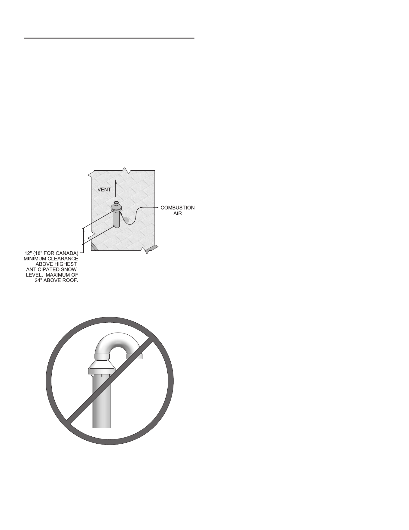
36
2. Cut one (1) hole (5 inch diameter for #100274637 installations
or 7 inch diameter for #100274638 installations) into the
structure to install the termination kit.
3. Partially assemble the concentric vent termination kit. Clean
and cement following the cleaning procedures in these
instructions.
a. Cement the Y concentric fi tting to the larger diameter kit
pipe (see Figure’s 36 and 37 on Page 28).
b. Cement rain cap to the smaller diameter kit pipe (see
Figure’s 36 and 37 on Page 28).
c. Do not attach a U-Bend to the rain cap. Doing so could
cause recirculation (see Figure 48).
NOTE: Instead of cementing the smaller pipe to the rain cap, a
fi eld supplied stainless steel screw may be used to secure the
two (2) components together when fi eld disassembly is desired
for cleaning (see Figure 40 on Page 29).
When using the alternate screw assembly method, drill a
clearance hole in the rain cap and a pilot hole in the vent pipe
for the screw size being used. Failure to drill adequate holes
may cause cracking of PVC components, allowing combustion
products to be recirculated. Failure to follow this warning could
result in personal injury or death.
VERTICAL TERMINATION - OPTIONAL CONCENTRIC
VENT: MODELS 150 - 600
DESCRIPTION AND USAGE
A. O. Smith offers an optional concentric combustion air and vent
pipe termination kit. Both combustion air and vent pipes must
attach to the termination kit. The termination kit must terminate
outside the structure and must be installed as shown in Figure
47.
Field supplied pipe and fi ttings are required to complete the
installation.
The required combustion vent pipe and fi ttings are listed in Table
8, on Page 19 of this manual.
VERTICAL TERMINATION INSTALLATION
1. See Vertical Direct Venting - Determine Location (where
applicable).
Figure 47. Concentric Vertical Termination
Figure 48. Do Not Install U-Bend to Rain Cap
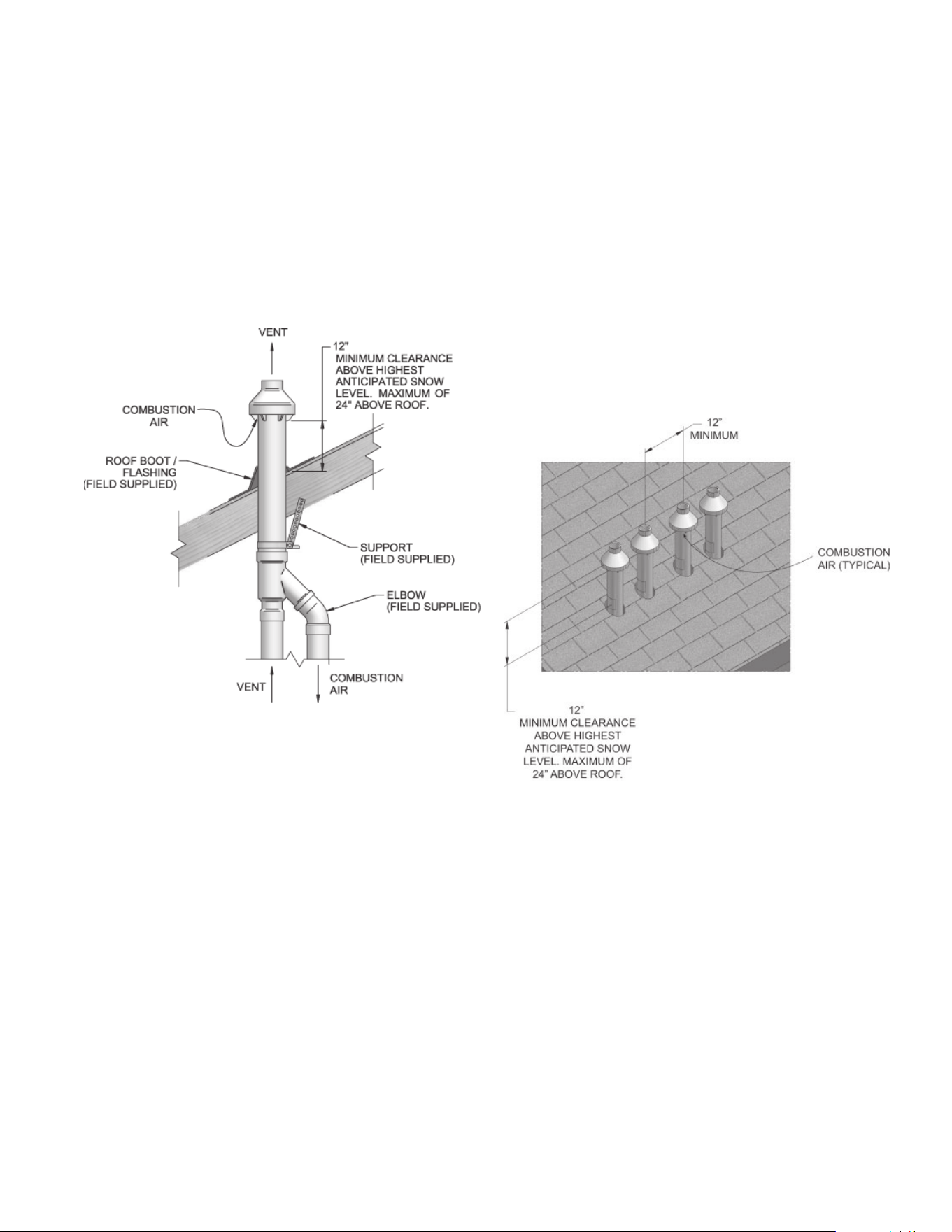
37
6. Install the rain cap and the small diameter pipe assembly into
the roof penetration assembly. Ensure the small diameter
pipe is cemented and bottomed in the Y concentric fi tting for
#100274637 installations and fastened tightly into the rubber
adapter for #100274638 installations.
7. Cement the appliance combustion air and vent pipes to the
concentric vent termination assembly. See Figure 49 for
proper pipe attachment.
8. Operate the appliance through one (1) heat cycle to ensure
combustion air and vent pipes are properly connected to the
concentric vent termination connections.
MULTIPLE VERTICAL TERMINATIONS
When two (2) or more direct vent appliances are vented near
each other, each appliance must be individually vented (see
Figure 50). NEVER common vent or breach vent this appliance.
When two (2) or more direct vent appliances are vented near
each other, two (2) vent terminations may be installed as shown
in Figure 50. It is important that vent terminations be made as
shown to avoid recirculation of fl ue gases.
Do not operate the appliance with the rain cap removed or
recirculation of combustion products may occur. Water may
also collect inside the larger combustion air pipe and fl ow to the
burner enclosure. Failure to follow this warning could result in
product damage or improper operation, personal injury, or death.
4. Install the Y concentric fi tting pipe assembly up through the
structure’s hole and fi eld supplied roof boot/fl ashing.
NOTE: Do not allow insulation or other materials to accumulate
inside the pipe assembly when installing through the hole.
5. Secure the assembly to the roof structure as shown below in
Figure 49 using fi eld supplied metal strapping or equivalent
support material.
Figure 49. Concentric Vent Roof Installation
NOTE: Ensure termination height is above the roof surface or
anticipated snow level (12 inches in U.S.A.) as shown in Figure
47 on Page 33.
If assembly is too short to meet height requirement, the two
(2) pipes supplied in the kit may be replaced by using the
same diameter, fi eld supplied SDR-26 PVC (D2241) pipe for
100274637 and standard schedule 40 PVC for 100274638. Do
not extend dimension D* more than 60 inches (see Figure’s 36
and 37 on Page 29).
DO NOT use fi eld-supplied couplings to extend pipes. Airfl ow
restriction will occur.
Figure 50. Concentric Vent and Combustion Air Vertical
Termination
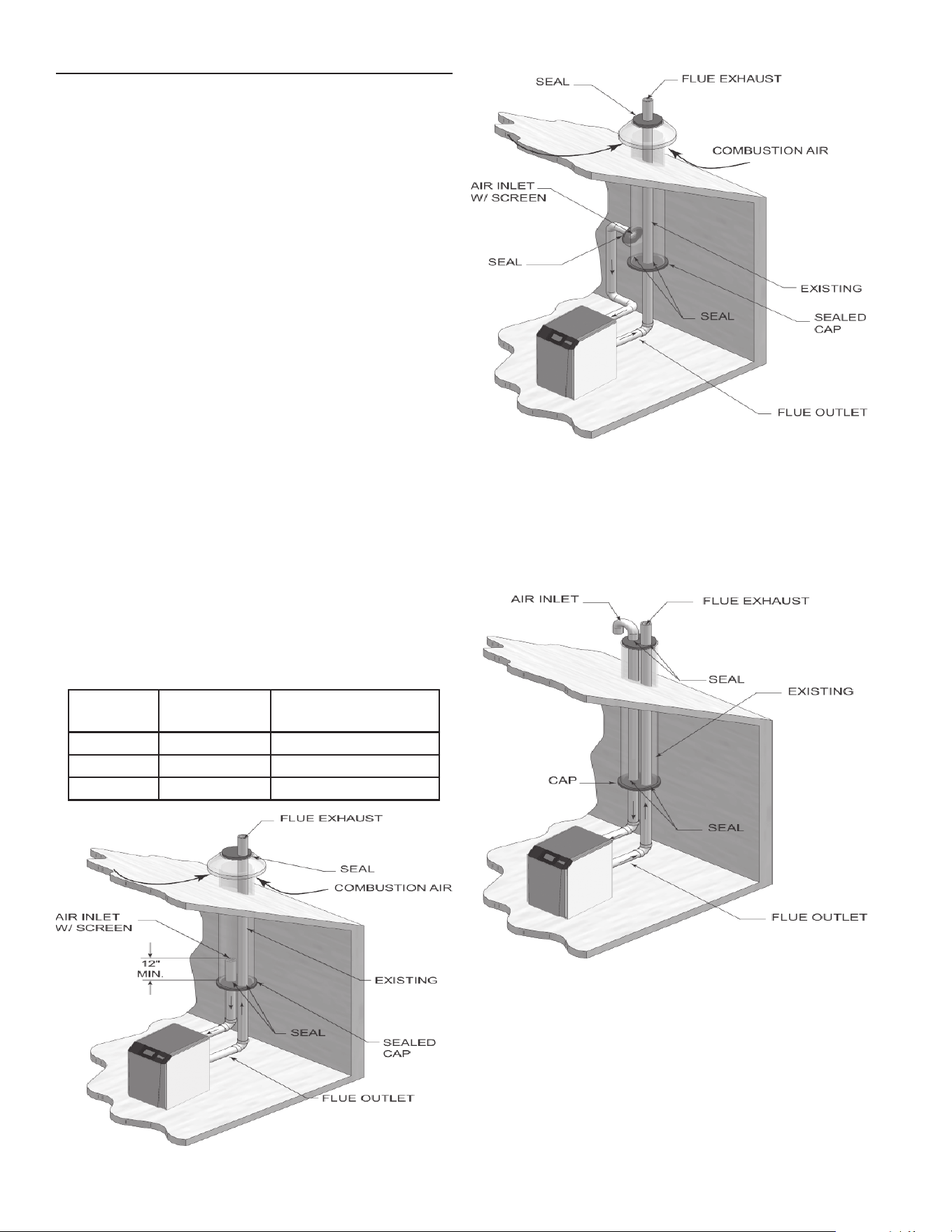
38
ALTERNATE VERTICAL CONCENTRIC VENTING
This appliance may be installed with a concentric vent
arrangement where the vent pipe is routed through an existing
unused venting system; or by using the existing unused venting
system as a chase for vent and combustion air routing.
CONCENTRIC VENTING ARRANGEMENT
The venting is to be vertical through the roof. The annular space
between the O.D. of the vent pipe and the I.D. of the existing
unused venting system is utilized for the combustion air source.
The minimum size of the existing vent system required to achieve
enough annular space for combustion air can be found in Table
19 below.
The upper and lower termination as well as any other unsealed
joints in the existing vent system must be sealed to ensure that
all combustion air is drawn from under the vent cap as shown in
Figure’s 51 and 52.
Approved venting materials must be used as specifi ed in Table
8 on Page 19.
Follow all vent / air termination and clearance requirements per
this section to the appropriate example. Installation must comply
with local requirements and with the National Fuel Gas Code.
The maximum allowable equivalent vent and air intake lengths
for this venting arrangement are to be determined from the
Venting Installation section.
If an existing unused venting system is converted for use with
this method of concentric venting, the installer must ensure that
the existing venting system is clean and free from particulate
contamination that will harm this appliance and cause increased
nuisance calls or maintenance. Refer to Page 11 for a list of
corrosive contaminants and sources.
Two example scenarios of a concentric venting arrangement are
shown for illustrative purposes in Figure’s 51 and 52.
Table 19. Alternate Vertical Concentric Vent / Chase Sizes
MODEL VENT/ AIR
INLET SIZE
MINIMUM EXISTING
VENT / CHASE SIZE
150 - 200 3" 5"
285 - 600 4" 7"
700 - 800 6" 10"
Figure 51. Concentric Vent Example 1
Figure 52. Concentric Vent Example 2
EXISTING VENT AS A CHASE
Follow all existing termination and clearance requirements and
allowable pipe lengths. Use only approved venting materials
listed in the Venting Installation section of this manual.
Figure 53. Existing Vent as a Chase
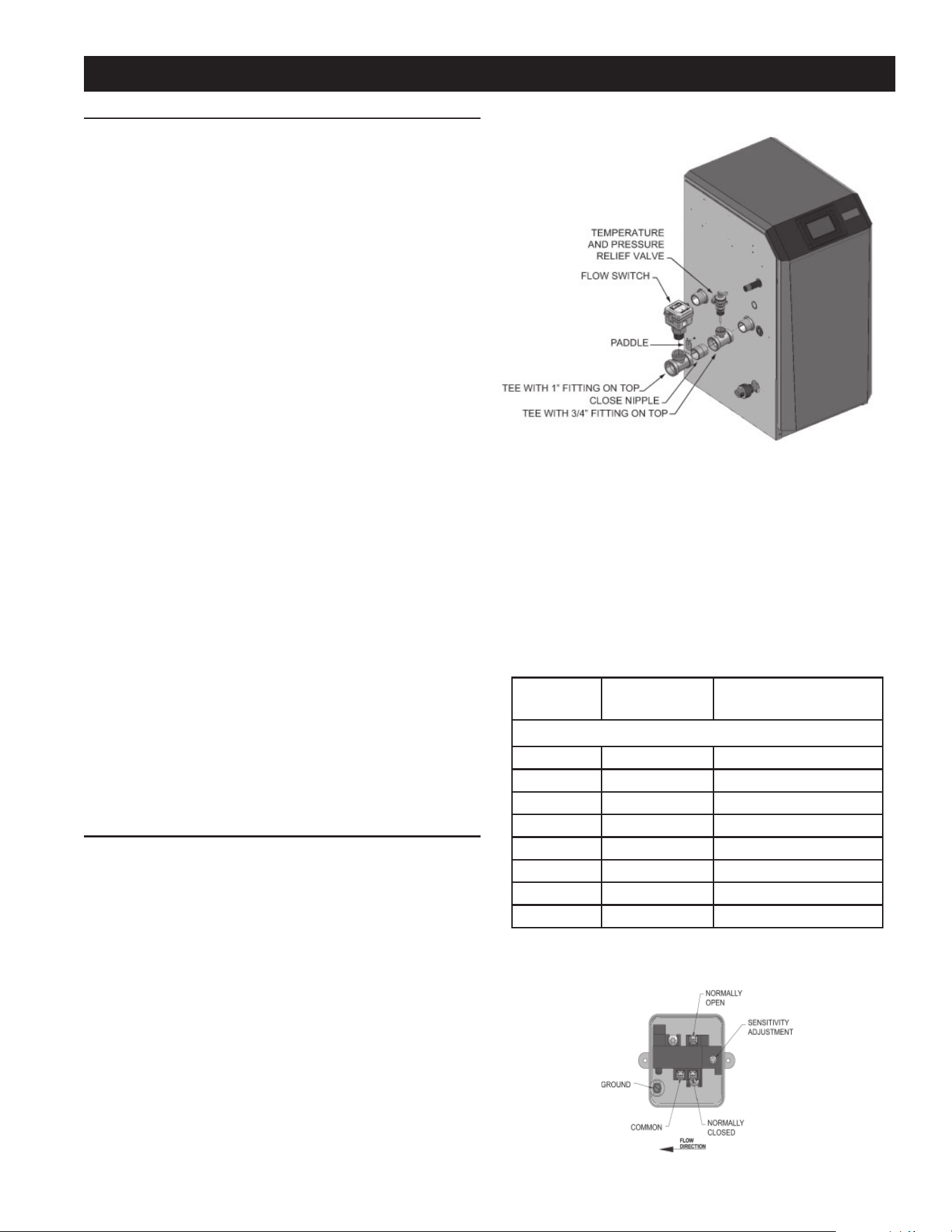
39
NOTE: Be sure to install fl ow switch so that the arrow on the fl ow
switch is pointing in the direction of the fl ow (see Figure 55).
FLOW SWITCH ADJUSTMENT
Refer to Table 20 for the proper setting of the sensitivity screw.
For reference, the position of the screw prior to setting should be
turned clockwise with a Phillips driver until it stops (Figure 55).
Proceed to turn the screw counterclockwise the amount of turns
listed in Table 20 based on the model.
Consult the manufacturer’s instructions for wiring the fl ow switch
to your system.
Table 20. Paddle Size / Sensitivity Screw Adjustment
MODEL PADDLE SIZE SENSITIVITY SCREW
ADJUSTMENT
Note: Paddles are included with the fl ow switch.
150 #1 9 turns
200 #1 6 turns
285 #3 8¾ turns
400 #1 8 turns
500 #1 7½ turns
600 #1 7 turns
700 #1 6½ turns
800 #1 5½ turns
NOTE: Turn the sensitivity screw clockwise to increase the fl ow
rate required to activate the switch. Turn the sensitivity screw
counterclockwise to decrease the fl ow rate required to activate
the switch.
WATER HEATER INSTALLATION
SYSTEM PIPING
Observe a minimum of 1/4 inch clearance around all un insulated
hot water pipes when openings around the pipes are not
protected by non-combustible materials.
GENERAL PIPING INFORMATION
Basic steps are listed below along with illustrations on the
following pages (Figure’s 57 thru 60), which will guide you
through the installation of the XP water heater.
1. Connect the cold water supply to the inlet side of the water
heater.
2. Connect the hot water supply to the outlet side of the water
heater.
3. Install a backfl ow preventer or check valve on the cold feed
make-up water line.
4. Install the factory supplied pump as shown in Figure’s 57 thru
60.
5. Install an expansion tank on the system supply. Consult
the tank manufacturer’s instruction for specifi c information
relating to tank installation. Size the expansion tank for the
required system volume and capacity.
6. Install a drain valve at the lowest point of the system.
7. This appliance is supplied with a Temperature & Pressure
Relief Valve sized in accordance with ASME Boiler and
Pressure Vessel Code, Section IV (“Heating Boilers”). Pipe
the discharge of the safety T & P Relief Valve to a suitable
drain to prevent injury in the event of pressure relief. Pipe the
discharge to a drain. Provide piping that is the same size as
the safety T & P Relief Valve outlet. Never block the outlet of
the safety T & P Relief Valve.
The T & P Relief Valve, tee and other necessary fi ttings are
shipped in the install kit with the water heater and are to be fi eld
installed. See the piping illustrations included in this section,
Figure 57 thru Figure 60 for suggested guidelines in piping the
XP water heater.
NOTE: *Please note that these illustrations are meant to show
system piping concept only, the installer is responsible for all
equipment and detailing required by local codes.
FLOW SWITCH AND TEMPERATURE & PRESSURE
RELIEF VALVE (T & P RELIEF VALVE) INSTALLATION
Basic steps are listed below to guide you through the installation
of the fl ow switch and T & P Relief Valve provided with the unit.
1. Install the tee with the 3/4 inch fi tting positioned vertically
and on the top as shown in Figure 54.
2. Install the T & P Relief Valve into the 3/4 inch fi tting of the tee
installed in Step 1 (Figure 54).
3. Install the close nipple on the downstream side of the
temperature and pressure relief valve tee (Figure 54).
4. Install the tee with the 1 inch fi tting positioned vertically and
on the top (Figure 54).
5. Attach the paddle to the fl ow switch per the manufacturer’s
instructions. Reference Table 20 to select the correct
paddle for the pipe size used (consult the manufacturer’s
instructions for a detailed explanation). For Example: If
using a 1 1/4 inch pipe size (Models XWH 150 - XWH 200)
select paddle #1.
6. Install the assembled fl ow switch into the 1 inch fi tting of the
tee installed in Step 4 (see Figure 54).
Figure 54. Flow Switch and T & P Relief Valve Installation
Figure 55. Flow Switch Adjustment
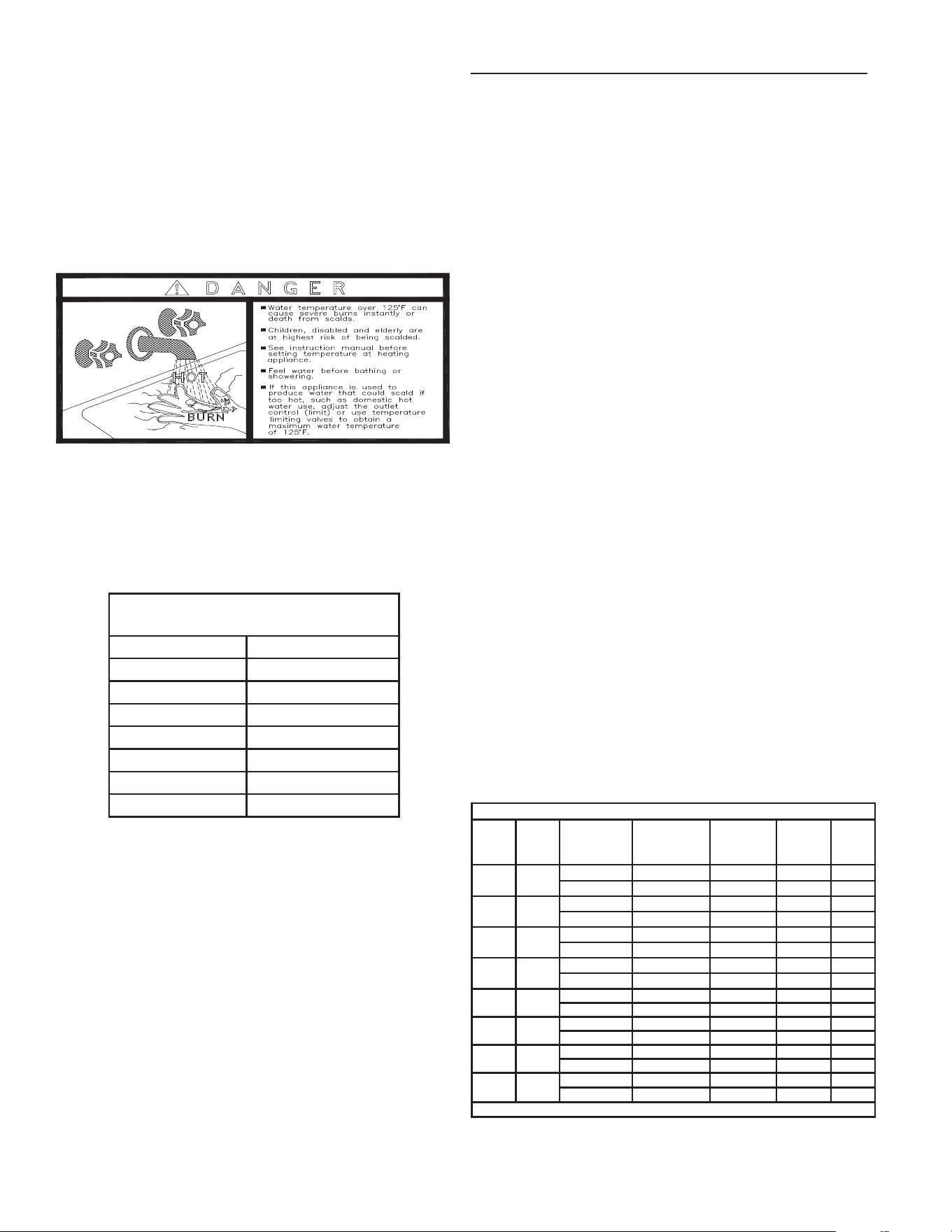
40
SCALDING
This water heater can deliver scalding temperature water at any
faucet in the system. Be careful whenever using hot water to avoid
scalding injury. Certain appliances such as dishwashers and
automatic clothes washers may require increased temperature
water. By setting the thermostat on this water heater to obtain the
increased temperature water required by these appliances, you
may create the potential for scald injury. To protect against injury,
you should install a mixing valve in the water system. This valve
will reduce point of discharge temperature by mixing cold and hot
water in branch supply lines. Such valves are available from the
local plumbing supplier.
The following chart (Table 21) details the relationship of water
temperature and time with regard to scald injury and may be
used as a guide in determining the safest water temperature for
your applications.
Table 21. Approximate Time / Temperature Scald Chart
APPROXIMATE TIME / TEMPERATURE
RELATIONSHIPS IN SCALDS
120°F More than 5 minutes
125°F 1 1/2 to 2 minutes
130°F About 30 seconds
135°F About 10 seconds
140°F Less than 5 seconds
145°F Less than 3 seconds
150°F About 1 1/2 seconds
155°F About 1 second
WATER CHEMISTRY
NOTE: The temperature rises and circulating pumps shown in
Table 22 are sized based on the heating of potable water with a
specifi ed water chemistry. See Table 24 in Start Up Section for
recommendations. Heating of high hardness and/or high total
dissolved solids water may require a larger circulating pump,
and a revised temperature rise specifi cation based on the water
chemistry of the water to be heated. See Table 24 in Start Up
Section for recommendations.
Water with a hardness of less than 5 grains per gallon will usually
have a pH which can be aggressive and corrosive causing
non-warrantable damage to the pump, and associated piping.
Corrosion due to water chemistry generally shows up fi rst in the
hot water system because heated water increases the rate of
corrosive chemical reactions.
PIPING COMPONENTS
WATER HEATER SYSTEM PIPING
Water heater system piping MUST be sized per the pipe
requirements listed in Table 22. Reducing the pipe size can
restrict the fl ow rate through the water heater, causing inadvertent
high limit shutdowns and poor system performance.
CHECK VALVES:
Field supplied. Check valves are recommended for installation
as shown in Figure’s 57 thru 60.
WATER HEATER ISOLATION VALVES:
Field supplied. Full port ball valves are required. Failure to use
full port ball valves could result in a restricted fl ow rate through
the water heater.
ANTI-SCALD MIXING VALVE:
Field supplied. An anti-scald mixing valve is recommended when
storing domestic hot water above 115°F.
UNIONS:
Field supplied. Recommended for unit serviceability.
TEMPERATURE AND PRESSURE RELIEF VALVE:
Factory supplied on water heaters. The T & P relief valve is sized
to ASME specifi cations. Storage tanks may require additional
valves depending on local codes.
TANK SENSOR:
A. O. Smith supplies a tank sensor. The tank sensor must be
installed in the tapping provided in the lower 25% of the storage
tank to achieve proper operation. As shipped from the factory,
the tank sensor is in the literature package shipped with the unit.
Placing the sensor in the tapping provided on the storage tank
will improve temperature response and prevent short cycles of
operation.
STRAINER:
Field supplied. Required to help eliminate debris from causing
damage to the heat exchanger. When installing in a pre-existing
system, it is recommended to install a filter in the recirculation
line capable of removing debris left in the system.
Table 22. Water Heater Pump Applications / Typical
Temperature Rise
NOTE: Pump selections and fl ow shown above are based on
45 feet of piping, 4 - 90° elbows, and 2 - fully ported ball valves.
Figure 56. Scald Warning Label Located on the Appliance
Water Heater Pump Applications
Model
Pipe
Size
Water
Hardness
*Grundfos
Flow
Rate
(GPM)
Loss
(FT/HD)
Temp.
Rise
150 1-1/4"
5 to 12 gpg *UP 43-100 SF 16 20 18°F
12 to 15 gpg TP 40-160 24 41 12°F
200 1-1/4"
5 to 12 gpg *UP 43-100 SF 21 22 18°F
12 to 15 gpg TP 40-160 28 38 13°F
285 2"
5 to 12 gpg *UP 43-100 SF 30 23 18°F
12 to 15 gpg TP 40-160 38 36 14°F
400 2"
5 to 12 gpg *UP 43-110 SF 42 31 18°F
12 to 15 gpg TP 40-240 56 48 13°F
500 2"
5 to 12 gpg *UP 43-110 SF 53 26 18°F
12 to 15 gpg TP 40-240 66 43 14°F
600 2"
5 to 12 gpg *UP 43-110 SF 53 26 22°F
12 to 15 gpg TP 40-240 66 43 17°F
700 2"
5 to 12 gpg *TP 40-160 63 32 22°F
12 to 15 gpg TP 50-160/2B 75 46 17°F
800 2"
5 to 12 gpg *TP 40-160 67 31 24°F
12 to 15 gpg TP 50-160/2B 85 43 18°F
*Denotes standard pump supplied with unit.
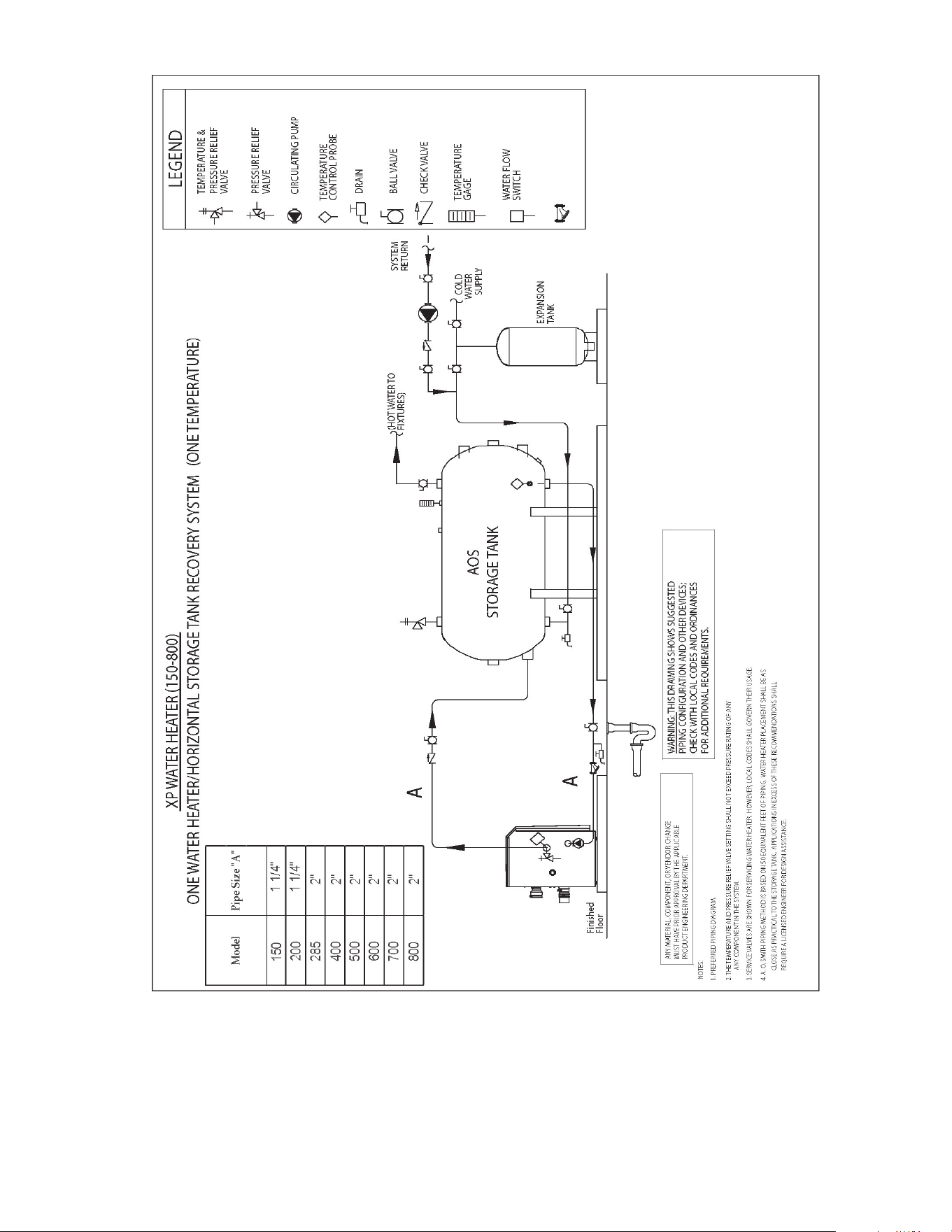
41
Figure 57. ONE WATER HEATER/ HORIZONTAL STORAGE TANK RECOVERY SYSTEM
NOTE: Please note that these illustrations are meant to show system piping concept only, the installer is responsible for all equipment.
The installer must follow all manufacturer’s instructions for each system component. The installer is responsible for compliance with
local codes.
The piping will not support the weight of the water heater circulator pump. Do not attempt to support the weight of the water heater
circulator pump with the piping or its accessories. Refer to the pump manufacturer’s installation instructions. Failure to comply could
result in severe personal injury, death, or substantial property damage.
Y-STRAINER
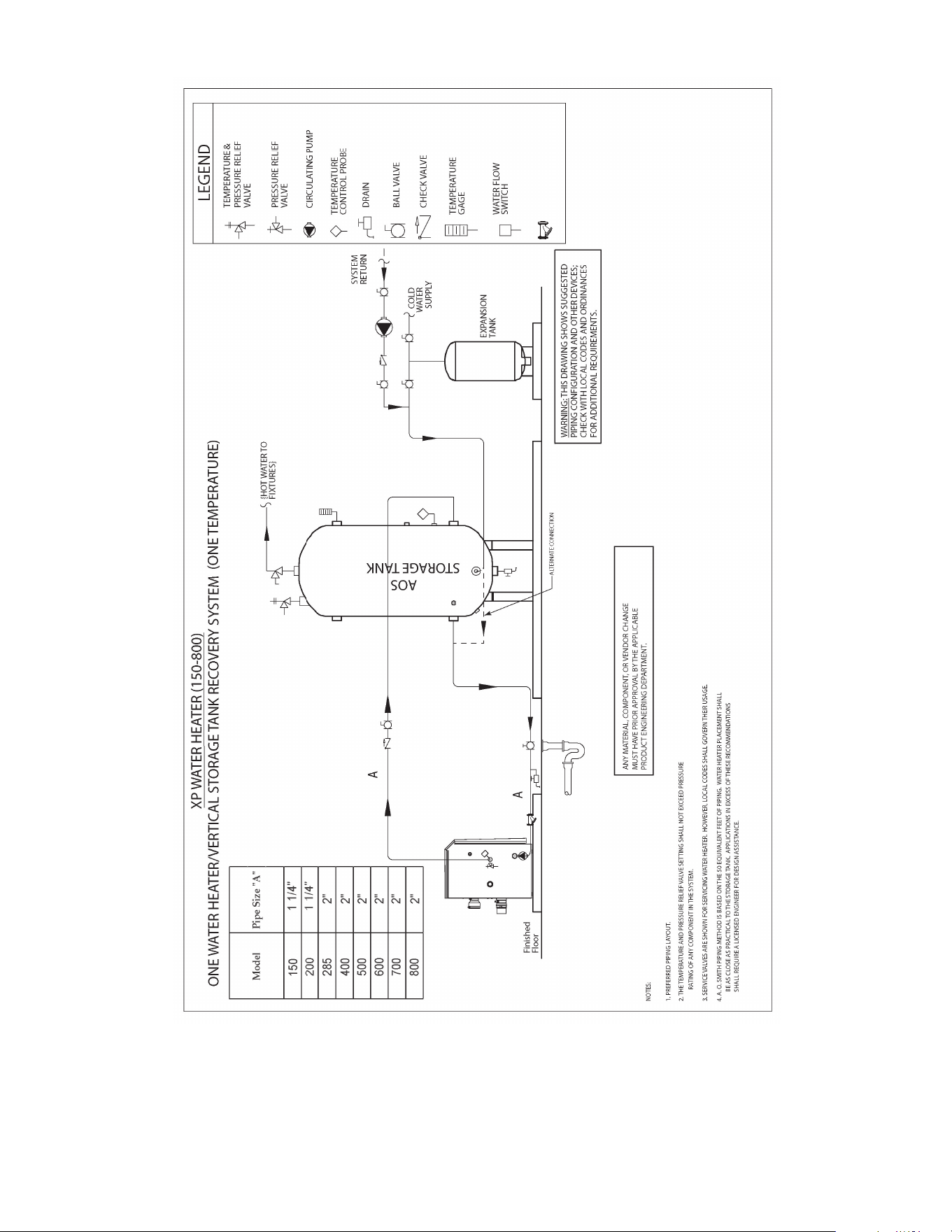
42
NOTE: Please note that these illustrations are meant to show system piping concept only, the installer is responsible for all equipment.
The installer must follow all manufacturer’s instructions for each system component. The installer is responsible for compliance with
local codes.
The piping will not support the weight of the water heater circulator pump. Do not attempt to support the weight of the water heater
circulator pump with the piping or its accessories. Refer to the pump manufacturer’s installation instructions. Failure to comply could
result in severe personal injury, death, or substantial property damage.
Y-STRAINER
Figure 58. ONE WATER HEATER/ VERTICAL STORAGE TANK RECOVERY SYSTEM
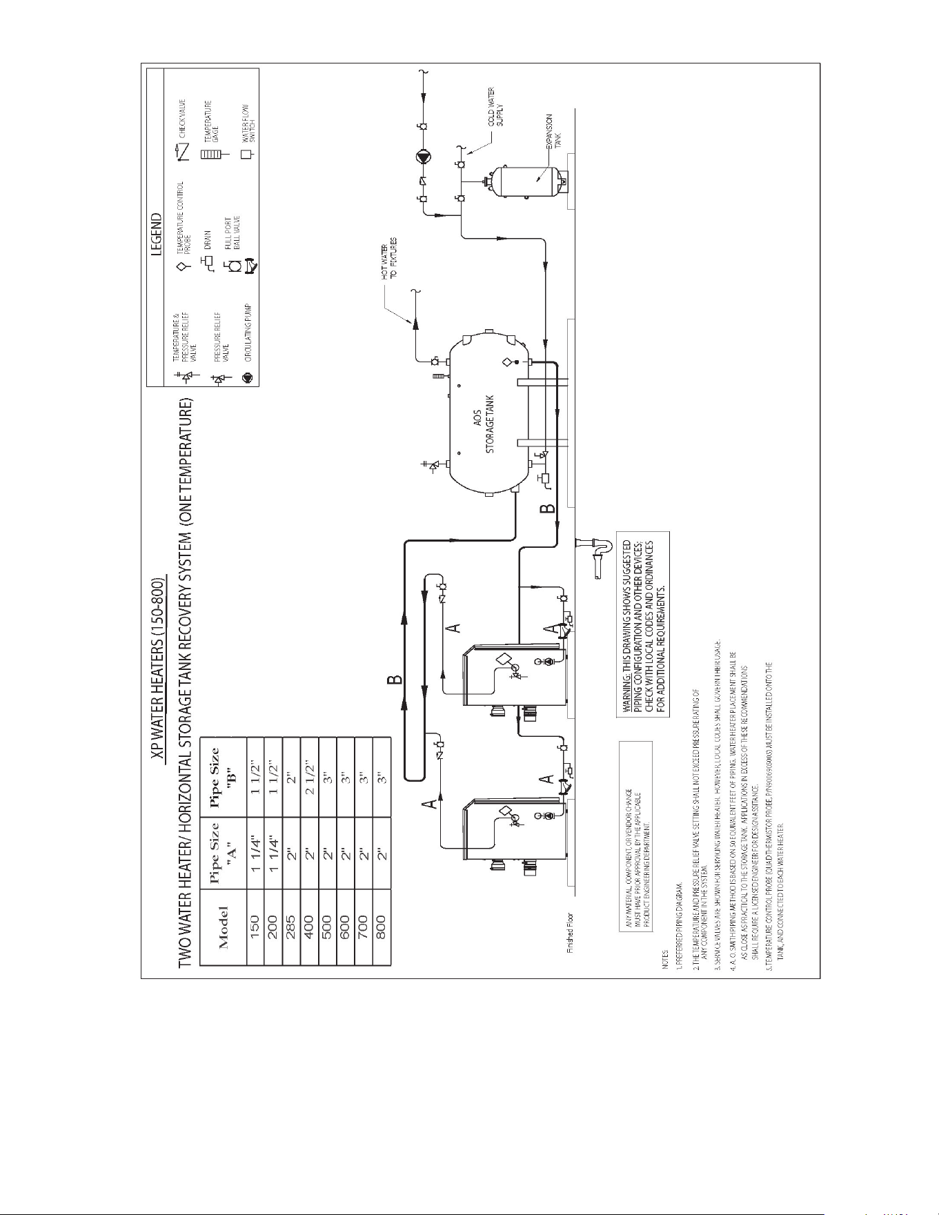
43
Figure 59. TWO WATER HEATER/ HORIZONTAL STORAGE TANK RECOVERY SYSTEM
NOTE: Please note that these illustrations are meant to show system piping concept only, the installer is responsible for all equipment.
The installer must follow all manufacturer’s instructions for each system component. The installer is responsible for compliance with
local codes.
The piping will not support the weight of the water heater circulator pump. Do not attempt to support the weight of the water heater
circulator pump with the piping or its accessories. Refer to the pump manufacturer’s installation instructions. Failure to comply could
result in severe personal injury, death, or substantial property damage.
Y-STRAINER
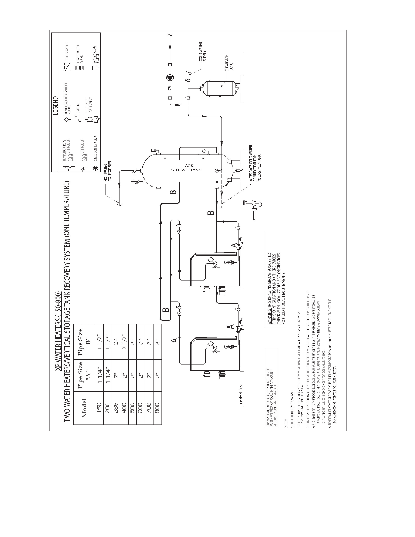
44
NOTE: Please note that these illustrations are meant to show system piping concept only, the installer is responsible for all equipment.
The installer must follow all manufacturer’s instructions for each system component. The installer is responsible for compliance with
local codes.
The piping will not support the weight of the water heater circulator pump. Do not attempt to support the weight of the water heater
circulator pump with the piping or its accessories. Refer to the pump manufacturer’s installation instructions. Failure to comply could
result in severe personal injury, death, or substantial property damage.
Y-STRAINER
Figure 60. TWO WATER HEATER/ VERTICAL STORAGE TANK RECOVERY SYSTEM
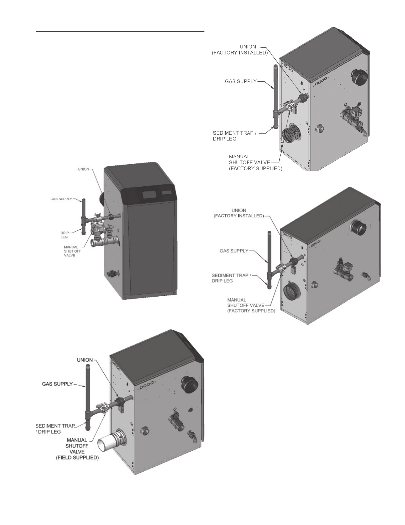
45
The gas valve and blower will not support the weight of the
piping. Do not attempt to support the weight of the piping with the
water heater or its accessories. Failure to comply could result in
severe personal injury, death, or substantial property damage.
4. Purge all air from the gas supply piping.
5. Before placing the water heater in operation, check the water
heater and its gas connection for leaks.
a. The appliance must be disconnected from the gas supply
piping system during any pressure testing of that system at a
test pressure in excess of 1/2 PSIG (3.5 kPa).
b. The appliance must be isolated from the gas supply piping
system by closing a manual shutoff valve during any pressure
testing of the gas supply piping system at test pressures
equal to or less than 1/2 PSIG (3.5 kPa).
c. The appliance and its gas connection must be leak tested
before placing it in operation.
GAS CONNECTIONS
CONNECTING GAS SUPPLY PIPING
1. Remove the top access panel and refer to Figure’s 61 thru 64
to pipe gas to the water heater.
a. Install ground joint union for servicing, when required.
b. On Models 150 - 400 install a manual shutoff valve in the
gas supply piping outside water heater jacket when required
by local codes or utility requirements.
2. Install sediment trap / drip leg.
Water heater system piping MUST be sized per the
pipe requirements listed in Table 22. Reducing the pipe
size can restrict the fl ow rate through the water heater,
causing inadvertent high limit shutdowns and poor system
performance.
3. Support piping with hangers, not by the water heater or its
accessories.
Figure 61. Gas Supply Piping - Models 150 - 200
Figure 62. Gas Supply Piping - Models 285 - 400
Figure 63. Gas Supply Piping - Models 500
Figure 64. Gas Supply Piping - Models 600 - 800
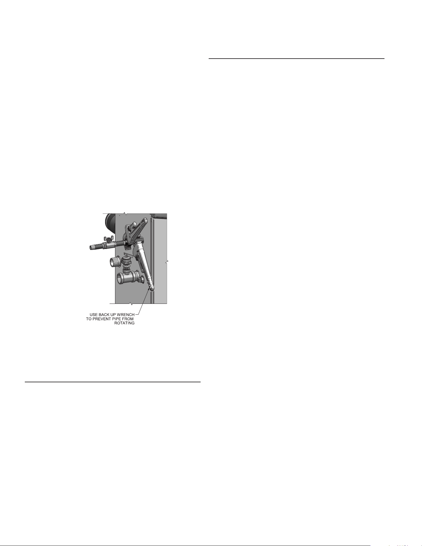
46
2. Install 100% lockup gas pressure regulator in supply line if
inlet pressure can exceed 14 inches w.c. at any time. Adjust
lockup regulator for 14 inches w.c. maximum.
PROPANE (LP) GAS
XP water heaters are typically shipped ready to fi re on natural
gas. Check water heater rating plate to determine which fuel the
water heater is set for. If set to natural gas, it may be converted
to Propane (LP) by installing an orifi ce or by making a gas
valve adjustment (see pages 13 thru 15). In order to operate on
Propane (LP) gas, an orifi ce MUST BE installed or a gas valve
adjustment MUST BE made. Failure to comply could result in
severe personal injury, death, or substantial property damage.
PIPE SIZING FOR PROPANE GAS
1. Contact gas supplier to size pipes, tanks, and 100% lockup
gas pressure regulator.
PROPANE SUPPLY PRESSURE REQUIREMENTS
1. Adjust propane supply regulator provided by the gas supplier
for 14 inches w.c. maximum pressure.
2. Pressure required at gas valve inlet pressure port:
• Maximum 14 inches w.c. with no fl ow (lockup) or with
water heater on.
• Minimum 8 inches w.c. with gas fl owing (verify during
water heater startup).
Ensure that the high gas pressure regulator is at least 6 - 10 feet
upstream of the appliance.
Do not check for gas leaks with an open fl ame – use the bubble
test. Failure to use the bubble test or check for gas leaks can
cause severe personal injury, death, or substantial property
damage.
6. Use pipe sealing compound compatible with propane gases.
Apply sparingly only to male threads of the pipe joints so that
pipe dope does not block gas fl ow.
Failure to apply pipe sealing compound as detailed in this
manual can result in severe personal injury, death, or substantial
property damage.
XP water heaters are typically shipped ready to fi re on natural
gas. Check the water heater rating plate to determine which
fuel the water heater is set for. If set to natural gas, it may be
converted to Propane (LP) by installing an orifi ce or by making a
gas valve adjustment (see pages 13 thru 15). In order to operate
on Propane (LP) gas, an orifi ce MUST BE installed or a gas valve
adjustment MUST BE made. Failure to comply could result in
severe personal injury, death, or substantial property damage.
Use two wrenches when tightening gas piping at water heater
(Figure 65), using one wrench to prevent the water heater gas
line connection from turning. Failure to support the water heater
gas connection pipe to prevent it from turning could damage gas
line components.
Figure 65. Inlet Pipe with Backup Wrench
NOTE: Maximum inlet gas pressure must not exceed the value
specifi ed. Minimum value listed is for the purposes of input
adjustment.
NATURAL GAS
PIPE SIZING FOR NATURAL GAS
1. Refer to Table 23 for pipe length and diameter. Based on
rated water heater input (divide by 1,000 to obtain cubic feet
per hour).
a. Table 23 is only for natural gas with specifi c gravity 0.60
inches, with a pressure drop through the gas piping of 0.30
inches w.c.
b. For additional gas pipe sizing information, refer to ANSI
Z223.1.
NATURAL GAS SUPPLY PRESSURE REQUIREMENTS
1. Pressure required at the gas valve inlet pressure port:
• Maximum 14 inches w.c. with no fl ow (lockup) or with
water heater on.
• Minimum 4 inches w.c. with gas fl owing (verify during
water heater startup).
47
8. Ensure inlet pressure is within specifi ed range. Minimum and
maximum gas supply pressures are specifi ed in this section
of the manual.
9. If gas supply pressure is within normal range and no
adjustments are needed, proceed on to Step 11.
10. If the gas pressure is out of range, contact the gas utility, gas
supplier, qualifi ed installer or service agency to determine
the necessary steps to provide proper gas pressure to the
control.
11. Turn the power switch to the “OFF” position.
12. Shut off the gas supply at the manual gas valve in the gas
piping to the appliance.
13. Remove the manometer from the pressure tap on top of the
gas valve. On Models 150 - 500 re-tighten the set screw
inside the pressure tap. On Models 600 - 800 remove the
1/8" (3 mm) fi eld supplied fi tting and reinstall the pipe plug
removed in Step 3.
When re-tightening the set screw, be sure to tighten securely to
prevent gas leaks. Do not check for gas leaks with an open fl ame
-- use the bubble test. Failure to use the bubble test or check for
gas leaks can cause severe personal injury, death, or substantial
property damage.
14. Turn on the gas supply at the manual gas valve.
15. Turn the power switch to the “ON” position.
16. Adjust the temperature Setpoint on the control panel of the
UIM to the desired water temperature so the appliance will
call for heat.
17. Check burner performance by cycling the system while you
observe burner response. The burner should ignite promptly.
Flame pattern should be stable. Turn system off and allow
burner to cool, then cycle burner again to ensure proper
ignition and fl ame characteristics.
Table 23. Natural Gas Pipe Size Chart
CAPACITY OF SCHEDULE 40 METALLIC PIPE IN CUBIC FEET OF NATURAL GAS PER HOUR
(BASED ON .60 SPECIFIC GRAVITY, 0.30" W.C. PRESSURE DROP)
Pipe
Size
(Inches)
Length of Pipe in Straight Feet
10 20 30 40 50 60 70 80 90 100 125 150 175 200
1/2 131 90 72 62 55 N/A N/A N/A N/A N/A N/A N/A N/A N/A
3/4 273 188 151 129 114 104 95 89 83 79 70 63 58 N/A
1 514 353 284 243 215 195 179 167 157 148 131 119 109 102
1 1/4 1,060 726 583 499 442 400 368 343 322 304 269 244 224 209
1 1/2 1,580 1,090 873 747 662 600 552 514 482 455 403 366 336 313
2 3,050 2,090 1,680 1,440 1,280 1,160 1,060 989 928 877 777 704 648 602
2 1/2 4,860 3,340 2,680 2,290 2,030 1,840 1,690 1,580 1,480 1,400 1,240 1,120 1,030 960
3 8,580 5,900 4,740 4,050 3,590 3,260 3,000 2,790 2,610 2,470 2,190 1,980 1,820 1,700
4 17,500 12,000 9,660 8,270 7,330 6,640 6,110 5,680 5,330 5,040 4,460 4,050 3,720 3,460
XP water heaters are typically shipped ready to fi re on natural gas. Check the water heater rating plate to determine which fuel the
water heater is set for. If set to natural gas, it may be converted to Propane (LP) by installing an orifi ce or by making a gas valve
adjustment (see pages 15 and 16). In order to operate on Propane (LP) gas, an orifi ce MUST BE installed or a gas valve adjustment
MUST BE made. Failure to comply could result in severe personal injury, death, or substantial property damage.
CHECK INLET GAS SUPPLY
CSA or UL listed fl exible gas connections are acceptable, but
you must exercise caution to ensure that the line has adequate
capacity to allow your water heater to fi re at full rate. Consult with
local codes for proper installation or service procedures.
DO NOT adjust or attempt to measure gas valve outlet pressure.
The gas valve is factory-set for the correct outlet pressure. This
setting is suitable for natural gas and propane, requiring no fi eld
adjustment. Attempting to alter or measure the gas valve outlet
pressure could result in damage to the valve, causing potential
severe personal injury, death, or substantial property damage.
The gas piping must be sized for the proper fl ow and length of
pipe, to avoid excessive pressure drop. Both the gas meter and
the gas regulator must be properly sized for the total gas load.
If you experience a pressure drop greater than 1 inch w.c., the
meter, regulator, or gas line is undersized or in need of service.
Perform the steps below when checking inlet gas supply:
1. Turn the main power switch to the “OFF” position.
2. Shut off gas supply at the manual gas valve in the gas piping
to the appliance.
3. On Models 150 - 500 loosen the set screw one (1) full turn
from inside the pressure tap on top of the gas valve. On
Models 600 - 800 remove the 1/8" (3 mm) pipe plug on the
inlet fl ange to the valve and install a suitable 1/8" (3 mm)
fi tting (fi eld supplied) for the manometer tubing. Place the
tubing of the manometer over the tap once the set screw is
loosened or the 1/8" (3 mm) fi tting is installed (depending on
model) as shown in Figure’s 66 thru 69 on Page 45.
4. Slowly turn on the gas supply at the fi eld installed manual
gas valve.
5. Turn the power switch to the “ON” position.
6. Adjust the temperature Setpoint on the control panel of the
Control Module to call for heat.
7. Observe the gas supply pressure as the burner fi res at 100%
of rated input. Percent of burner input will be displayed on
the control panel.
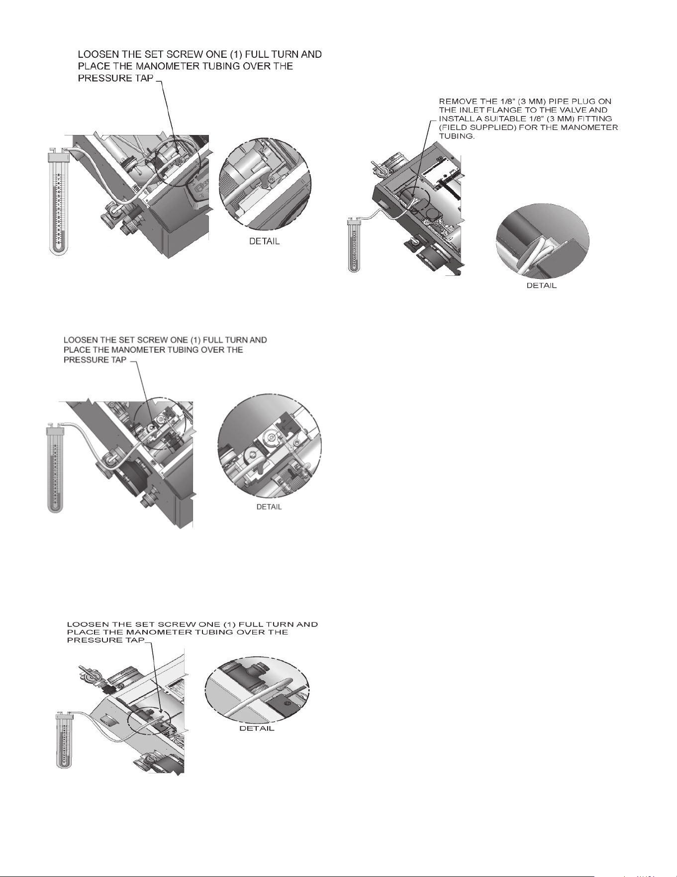
48
Figure 66. Inlet Gas Supply Check - Models 150 - 285
Figure 67. Inlet Gas Supply Check - Model 400
Figure 68. Inlet Gas Supply Check - Model 500
Figure 69. Inlet Gas Supply Check - Models 600 - 800
GAS PRESSURE
The gas pressure must remain between 4 inches w.c. (Natural), 8
inches w.c. (Propane (LP)) minimum and 14 inches w.c. (Natural
and Propane (LP)) maximum during stand-by (static) mode and
while in operating (dynamic) mode. If an in-line regulator is used,
it must be a minimum of 10 feet from the XP water heater. It is
very important that the gas line is properly purged by the gas
supplier or utility company. Failure to properly purge the lines or
improper line sizing, will result in ignition failure.
The problem is especially noticeable in NEW Propane (LP)
installations and also in empty tank situations. This can also
occur when a utility company shuts off service to an area to
provide maintenance to their lines.
GAS VALVE REPLACEMENT
The gas valve MUST NOT be replaced with a conventional gas
valve under any circumstances. As an additional safety feature,
this gas valve has a fl anged connection to the venturi and blower.
Failure to follow all precautions could result in fi re, explosion, or
death!
DO NOT adjust gas valve outlet pressure. The gas valve is
factory-set for the correct outlet pressure. This setting is suitable
for natural gas and propane, requiring no fi eld adjustment.
Attempting to alter the gas valve outlet pressure could result in
damage to the valve, causing potential severe personal injury,
death, or substantial property damage.
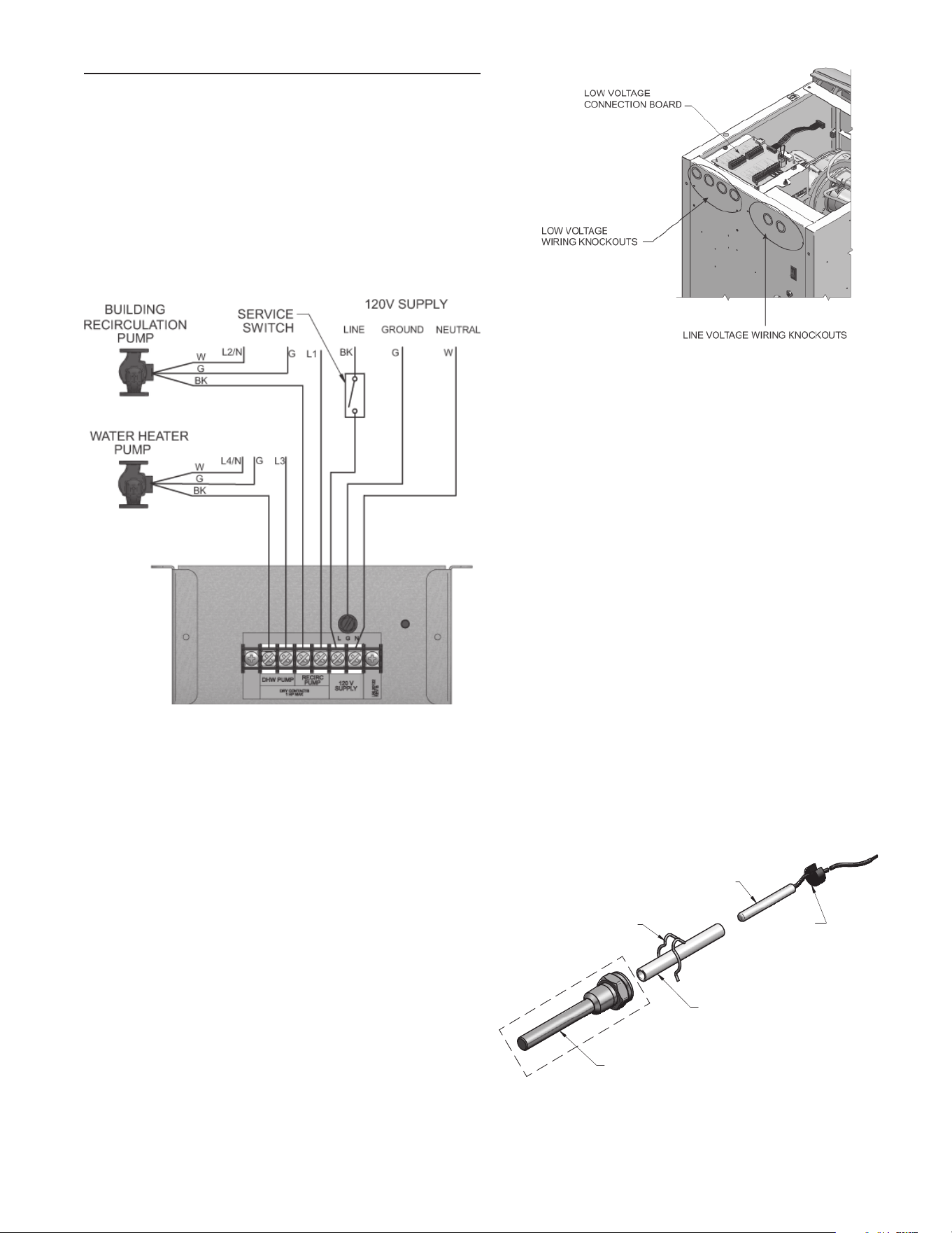
49
FIELD WIRING
ELECTRICAL SHOCK HAZARD – For your safety, turn off
electrical power supply before making any electrical connections
to avoid possible electric shock hazard. Failure to do so can
cause severe personal injury or death.
Wiring must be N.E.C. Class 1.
If original wiring as supplied with the water heater must be
replaced, use only type 105°C wire or equivalent.
The water heater must be electrically grounded as required by
National Electrical Code ANSI/NFPA 70 – latest edition.
Label all wires prior to disconnection when servicing controls.
Wiring errors can cause improper and dangerous operation.
INSTALLATION MUST COMPLY WITH:
1. National Electrical Code and any other national, state,
provincial, or local codes, or regulations.
LINE VOLTAGE CONNECTIONS
1. Connect 120 VAC power wiring to the line voltage terminal
strip in the junction box, as shown in Figure 70.
2. Provide and install a fused disconnect or service switch (15
amp recommended) as required by the code (see Figure
70).
3. The DHW (water heater) pump is shipped loose on all XP
models. Wire the water heater pump as shown in Figure 70.
4. The XP water heater is capable of controlling a building
recirculation pump (fi eld supplied). Wire the building
recirculation pump as shown in Figure 70.
5. Dry contacts are sized for 1 hp/120V, 2 hp/240V or 15A/120V,
25A/240V.
LINE VOLTAGE CONNECTIONS
1. Route all low voltage wires through the knockouts in the rear
of the water heater, as shown in Figure 71.
2. Connect low voltage wiring to low voltage connection board
as shown in Figure 72 on Page 48 of this manual and the
water heater wiring diagram.
Figure 70. Line Voltage Field Wiring Connections
TANK THERMOSTAT
1. Connect the tank thermostats (isolated contact only) to the
tank thermostat contacts as shown in Figure 72.
TANK SENSOR
NOTE: A tank sensor kit is provided with the unit and is the
preferred method of controlling the unit.
1. By installing a tank sensor, the Control Module can perform
the tank thermostat function more effi ciently with the tank
sensor. The Control Module automatically detects the
presence of this sensor and generates a DHW call for heat
when the tank temperature drops below the programmed
differential and fi nishes the call for heat when the tank
temperature reaches above the programmed offset.
2. The tank sensor provided with the kit is the only sensor
suitable for use with the Control Module.
3. A 3/4 inch tank brass bulb well is also provided with the kit.
The bulb well must be installed so that the shaft of the bulb
well is inside the tank. The bulb well must be tightened with
a socket to prevent damage. It is also recommeded to use a
small amount of thermal paste on the tip of the sensor.
4. Once the sensor and remaining components are installed,
connect the sensor to the tank sensor contacts as shown in
Figure 72.
Figure 71. Routing Field Wiring (Models 150 - 285)
T-STAT BULBWELL
USE SLEEVE WITH 3/8" ID BULBWELL
CLIP
SENSOR
GASKET
Figure 72. Tank Sensor With Bulbwell

50
WATER HEATER BUILDING MANAGEMENT SYSTEM (BMS)
1. An external control may be connected to control either the
fi ring rate or the set point of the water heater. If the external
control uses a set of contacts to enable the water heater,
connect the contacts to the Tank Thermostat terminals.
Otherwise, the Control Module will be enabled by the 0-10V
signal.
2. Make sure the (-) terminal is connected to the (-) or common
output terminal of the external control, and the (+) terminal
is connected to the (+) or 0 - 10 VDC terminal of the external
control. Make sure the (-) voltage is not below ground.
RUNTIME CONTACTS
The Control Module closes a set of dry contacts whenever the
burner is running. This is typically used by Building Management
Systems to verify that the water heater is responding to a call for
heat.
ALARM CONTACTS
The Control Module closes another set of contacts whenever the
water heater is locked out or the power is turned off. This can
be used to turn on an alarm, or signal a Building Management
System that the water heater is down.
WIRING OF THE LEAD/LAG
When wiring the water heaters for Lead/Lag operation, select
one water heater as the Leader water heater. The remaining
water heaters will be designated as Members. See page 58
“Confi guration of the Lead/Lag” for a detailed explanation of this
procedure.
Connect the tank sensor to the Leader water heater. For the Lead/
Lag system to work properly the tank sensor must be installed.
The tank sensor should be wired to the low voltage connection
board at the terminals marked for the tank sensor (see Figure
72). The Leader control will use the water temperature at the
tank sensor to control the operation of the Lead/Lag.
Communication between the Leader water heater and the
Member water heaters is accomplished by using shielded, 2-wire
twisted pair communication cable. Connect one of the twisted
pair wires to Lead/Lag terminal A on each of the Low Voltage
Connection boards, and the other wire of the twisted pair to Lead/
Lag terminal B on each of the Low Voltage Connection Boards.
Connect the shield wires to one of the shield terminals on the
Low Voltage Connection Boards (Figure 72). If more than two
water heaters are on the Lead/Lag, daisy chain the wiring from
the Lead/Lag terminals on the second water heater to the Lead/
Lag terminals on the third water heater, then from the third to the
forth, and so on. The connections between heaters can be made
in any order, regardless of the addresses of the water heaters.
Try to keep each cable as short as possible.
DAMPER RELAY
If dampers need to operate when the water heater fi res, they can
be controlled by this output. Connect these terminals to a 24 VAC
relay coil, which is wired to operate the dampers (Figure 72).
DAMPER PROVING SWITCH
When the operation of the dampers needs to be verifi ed before
the water heater fi res, remove the jumper wire from these
terminals and connect them to the normally open contacts on its
proving switch (Figure 72)
HIGH GAS PRESSURE SWITCH
If a switch is provided to detect excessive gas pressure, remove
the jumper wire from the terminals on the connection board, and
then connect them to its normally closed contacts (Figure 72).
LOW GAS PRESSURE SWITCH
1. If a switch is provided to detect low gas pressure, remove the
jumper wire from the terminals on the connection board and
connect them to its normally open contacts (Figure 72).
2. If both a high and low gas pressure switch are used, connect
their respective contacts in series, and connect them to the
terminals on the connection board (Figure 72).
See Gas Connections section on Page 42 for a detailed
explanation regarding high and low gas pressure switch
operation.
FLOW SWITCH
1. A fl ow switch is used to guarantee fl ow through the water
heater before allowing it to fi re. The fl ow switch must be
installed at the water heater outlet.
2. Connect these terminals to the normally open contacts on
the fl ow switch (Figure 72).
RATE OUTPUT
This output provides a 0 - 10V signal that is proportional to the
fi ring rate of the water heater. This may be used by a BMS system
to monitor the actual rate of the water heater.
MODBUS
When the optional ModBus interface module is installed, the RS-
485 ModBus cable is connected to these terminals. Use shielded,
2-wire twisted pair cable. If desired, the shield can be connected
to ground by installing a jumper wire between terminals 1 and 3
on connector X5 on the optional ModBus interface module.
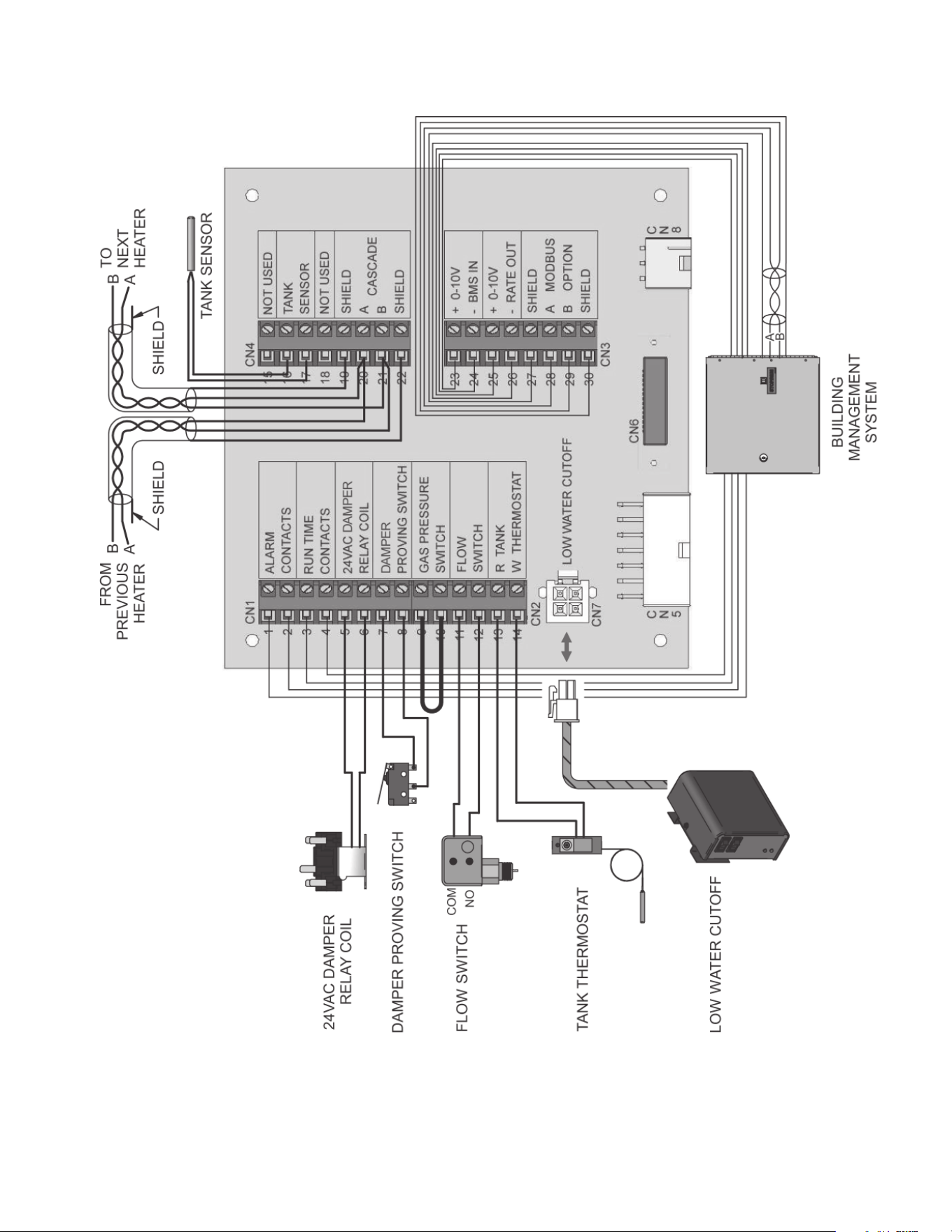
51
Figure 72. Low Voltage Field Wiring Connections
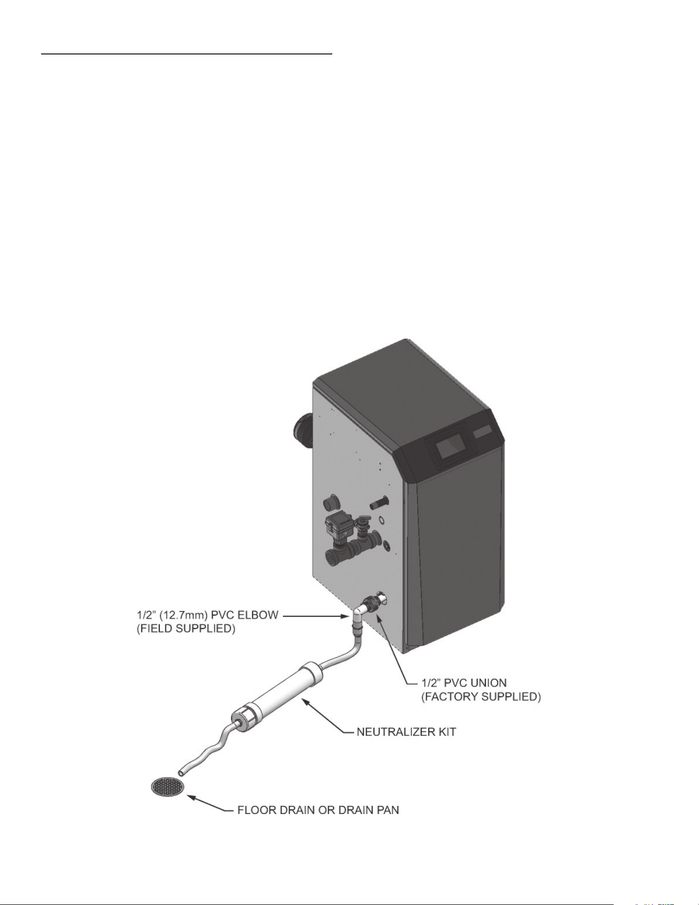
52
NOTE: Use materials approved by the authority having
jurisdiction. In the absence of other authority, PVC and CPVC
pipe must comply with ASTM D1785 or D2845. Cement and
primer must comply with ASME D2564 or F493.
NOTE: To allow for proper drainage on large horizontal runs, a
second line vent may be required and tubing size may need to
increase to 1 inch.
The condensate line must remain unobstructed, allowing free
fl ow of condensate. If condensate is allowed to freeze in the
line or if the line is obstructed in any other manner, condensate
can exit from the water heater tee, resulting in potential water
damage to property.
NOTE: DO NOT combine condensate drains from multiple
condensing appliances.
CONDENSATE DISPOSAL
CONDENSATE DRAIN
1. This water heater is a high effi ciency appliance that produces
condensate.
2. The side of the water heater has a 1/2 inch PVC union for
connection of a 1/2 inch PVC pipe (Figure 73).
3. Slope condensate tubing down and away from the water
heater into a drain or condensate neutralizing fi lter.
Condensate from the XP water heater will be slightly acidic
(typically with a pH from 3 to 5). Install a neutralizing fi lter if
required by local codes.
A Neutralizer Kit (Figure 73) is available from the factory
(100272807 for Models 150 - 500 and 100285867 for Models
600 - 800).
4. Install the 1/2 inch PVC elbow (fi eld supplied) as shown in
Figure 73.
5. Do not expose condensate line to freezing temperatures.
6. Use only plastic tubing or piping as a condensate drain line
(Figure 73).
Figure 73. Condensate Disposal
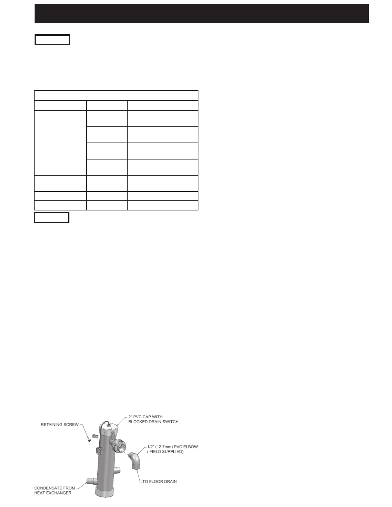
53
CHECK FOR GAS LEAKS
Before starting the water heater, and during initial operation,
smell near the fl oor and around the water heater for gas odorant
or any unusual odor. Remove the top access panel and smell
the interior of the water heater enclosure. Do not proceed with
startup if there is any indication of a gas leak. Use an approved
leak detection solution. Repair any leaks at once.
DO NOT adjust gas valve outlet pressure. The gas valve is
factory set for the correct outlet pressure. This setting is suitable
for natural gas and propane, requiring no fi eld adjustment.
Attempting to alter the gas valve outlet pressure could result in
damage to the valve, causing potential severe personal injury,
death, or substantial property damage.
Propane water heaters only – Your propane supplier mixes an
odorant with the propane to make its presence detectable. In
some instances, the odorant can fade, and the gas may no longer
have an odor. Before startup (and periodically thereafter), have
the propane supplier verify the correct odorant level in the gas.
INSPECT/FILL CONDENSATE SYSTEM
Inspect/check condensate lines and fi ttings
1. Inspect the condensate drain line, condensate PVC fi ttings
and condensate trap.
Fill condensate trap with water
1. Remove the PVC cap retaining screw from the PVC cap
(Figure 74).
2. Remove the 2 inch PVC cap with the switch located at the
top of the trap (Figure 74).
3. Fill with fresh water until the water begins to pour out of the
drain.
4. Replace the cap. Press the cap onto the trap until the cap
makes contact with the drain.
5. Replace the retaining screw.
The condensate trap (Figure 74) must be fi lled with water during
all times of water heater operation to avoid fl ue gas emission
from the condensate drain line. Failure to fi ll the trap could result
in severe personal injury or death.
FINAL CHECKS BEFORE STARTING THE WATER HEATER
• Read the XP Water Heater Service Handbook to familiarize
with Control Module operation. Read this manual, Pages 52
and 53 for proper steps to start the water heater.
• Verify the water heater and system are full of water and all
system components are correctly set for operation.
• Verify the preparation procedures of Pages 50 and 51 have
been completed.
• Fill the vent condensate trap with water (removing the
retaining screw in order to remove the 2 inch PVC cap with
the switch located at the top of the trap). Replace the cap.
Press the cap onto the trap until the cap makes contact with
the drain. Replace the retaining screw.
• Verify electrical connections are correct and securely
attached.
• Inspect vent piping and air piping for signs of deterioration
from corrosion, physical damage or sagging. Verify air
piping and vent piping are intact and correctly installed per
this manual.
START THE WATER HEATER
Read and follow the Operating instructions on Pages 52 and 53.
IF WATER HEATER DOES NOT START CORRECTLY
1. Check for loose connections, blown fuse or service switch
off?
2. Is water heater water temperature above 200°F?
3. Is tank thermostat or tank Setpoint set below room
temperature?
4. Is gas turned on at meter or water heater?
5. Is incoming gas pressure less than 4 inches w.c.?
If none of the above corrects the problem, refer to the
Troubleshooting section of the XP Water Heater Service
Handbook.
Figure 74. Condensate Trap
START UP
CHECK/CONTROL WATER CHEMISTRY
See the following table for properly operating the water heater
with the appropriate water chemistry. Good water quality will
help extend the life of the appliance by reducing the effects of
scale buildup and corrosion.
NOTICE
Conduct water quality testing prior to installing
the appliance. Various solutions are available to
adjust water quality.
WATER CHEMISTRY
Specifi cation Range Requirement
Hardness
< 5 gpg
Water treatment
required (See note 3)
5 to 12 gpg
Use Table 6C for pump
recommendation
12 to 15 gpg
Use Table 6C for pump
recommendation
> 15 gpg
Water softening system
required (See note 4)
Dissolved Solids < 350 ppm
Hardness level must be
met
pH Level 6.5 to 8.5 Acceptable range
Chloride < 150 ppm Acceptable range
Table 24. Water Chemistry
1. Do not use the water heater to directly heat
swimming pool or spa water.
2. At initial fill and during water heater start-up
and testing, check system thoroughly for any
leaks. Repair all leaks before proceeding
further.
3. When water treatment is required, contact a
commercial potable water treatment specialist
for recommendations to protect against system
corrosion.
4. When water softener is required, a Template
Assisted Crystallization system is
recommended.
NOTICE

54
7. Once the combustion analysis is complete, test the safety
shutoff device by turning the manual shutoff valve to the OFF
position and ensuring that the water heater shuts down and
registers an alarm. Open the manual shutoff valve and reset
the control, and return to Service Mode.
8. Turn the main power off to the water heater and replace the
fl ue temperature sensor into the fl ue pipe connection.
9. Place the water heater back into normal operation.
Replace the fl ue gas temperature sensor to prevent fl ue gas
spillage into the room. Failure to comply could result in severe
personal injury, death, or substantial property damage.
SET WATER HEATER OPERATION
Set Operating Setpoint temperature
1. From the Home screen on the Touch Screen Display press
the MENU button.
2. Under the MAIN MENU options select TEMPERATURES
and then press on 'TANK SETPOINT'.
3. Once the TANK SETPOINT screen appears, adjust the
desired MIN and MAX values using the + and – buttons.
4. Once the desired temperature is set, press the ACCEPT
button to upload the new temperature.
Verify WHR circulator mode
When the tank thermostat or tank sensor calls for heat, the
Control Module will turn on the water heater pump. When the
DHW call for heat ends, the water heater pump will continue to
run for a period of time. This pump delay is set at the factory to 60
seconds. If a shorter or longer delay is desired, the appropriate
parameter in the control must be changed. See the XP Water
Heater Service Handbook for a detailed explanation of this
procedure.
Set clock
The UIM has a built-in clock that it uses for its Setpoint Adjustment
feature and for logging events. This clock must be set when the
water heater is installed, and anytime the water heater has been
powered off for more than 4 hours. Use the following procedure
to set the clock:
1. From the Home screen on the Touch Screen Display press
the MENU button.
2. Under the MAIN MENU options select ECONOMY MODE/
CLOCK.
3. Select CURRENT TIME and CURRENT DATE and set the
current time and date using the + and – buttons.
4. Press the ACCEPT button to set the current changes.
NOTE: The internal clock does not adjust for Daylight Savings
Time and therefore, will require a manual adjustment. The clock
is automatically updated whenever a PC is connected and the
Win Pro-Installer program is started.
Confi guration of the Lead/Lag
When installed in a Lead/Lag system, the individual controls must
be programmed for Lead/Lag operation. This is accomplished
by accessing the control parameters under Control Modes and
Lead/Lag.
Select the parameter “Address” under Lead/Lag. Each appliance
in the Lead/Lag system must be programmed with its own
address. The water heater designated as the Leader will have an
address of 0. The remaining water heaters in the Lead/Lag will be
Members and have addresses from 1 - 7. Select the appropriate
address and upload the address into the control. Repeat this
procedure for all water heaters in the Lead/Lag, designating the
Leader control and the Member controls.
NOTE: A tank sensor must be installed when operating XP Water
Heaters in Lead/Lag.
Propane water heaters – verify conversion
1. Verify propane conversion has been completed per the
Propane Conversion instructions.
DO NOT adjust gas valve outlet pressure. The gas valve is
factory-set for the correct outlet pressure. This setting is suitable
for natural gas and propane, requiring no fi eld adjustment.
Attempting to alter the gas valve outlet pressure could result in
damage to the valve, causing potential severe personal injury,
death, or substantial property damage.
XP water heaters are typically shipped ready to fi re on natural
gas. Check water heater rating plate to determine which fuel the
water heater is set for. If set to natural gas, it may be converted
to Propane (LP) by installing an orifi ce or by making a gas
valve adjustment (see pages 15 and 16). In order to operate on
Propane (LP) gas, an orifi ce MUST BE installed or a gas valve
adjustment MUST BE made. Failure to comply could result in
severe personal injury, death, or substantial property damage.
CHECK FLAME AND COMBUSTION
1. Turn the main power off to the water heater by placing the
“On/Off” switch in the OFF position.
2. Remove the fl ue temperature sensor from the fl ue pipe
connection. Note: Combustion measurements will be made
at this point.
3. Turn the main power on to the water heater by placing the
“On/Off” switch in the ON position.
4. Press the RESET button on the Touch Screen Display. In
Service Mode the water heater will fi re at ignition speed and
will then modulate up to full fi re.
5. Insert the probe from a combustion analyzer into the hole
left by the removal of the fl ue temperature sensor.
6. Once the water heater has modulated up to full fi re, measure
the combustion. The values should be in the range listed in
Table 25 below. The CO levels should be less than 150 ppm
for a properly installed unit.
If the combustion is not within the specifi ed range, reference
the Troubleshooting section of the XP Water Heater Service
Handbook for possible causes and corrective actions.
Table 25. Flue Products Chart
NATURAL GAS PROPANE (LP)
CO
2
O
2
CO
2
O
2
8.0% - 10% 3.0% - 6.5% 9.0% - 11% 4.1% - 6.9%
CHECK SYSTEM AND WATER HEATER
Check water piping
1. Check system piping for leaks. If found, shut down the water
heater and repair immediately. (See WARNINGS on pages
53 and 54 (startup) regarding failure to repair leaks.)
2. Check Delta T. on Page 37 for more information.
3. Vent any remaining air from the system using manual vents.
Air in the system will interfere with circulation and cause heat
distribution problems and noise.
Check gas piping
1. Check around the water heater for gas odor following the
procedure on Page 42 of this manual (Connecting Gas
Supply Piping).
If you discover evidence of any gas leak, shut down the water
heater at once. Find the leak source with a bubble test and repair
immediately. Do not start the water heater again until corrected.
Failure to comply could result in severe personal injury, death, or
substantial property damage.
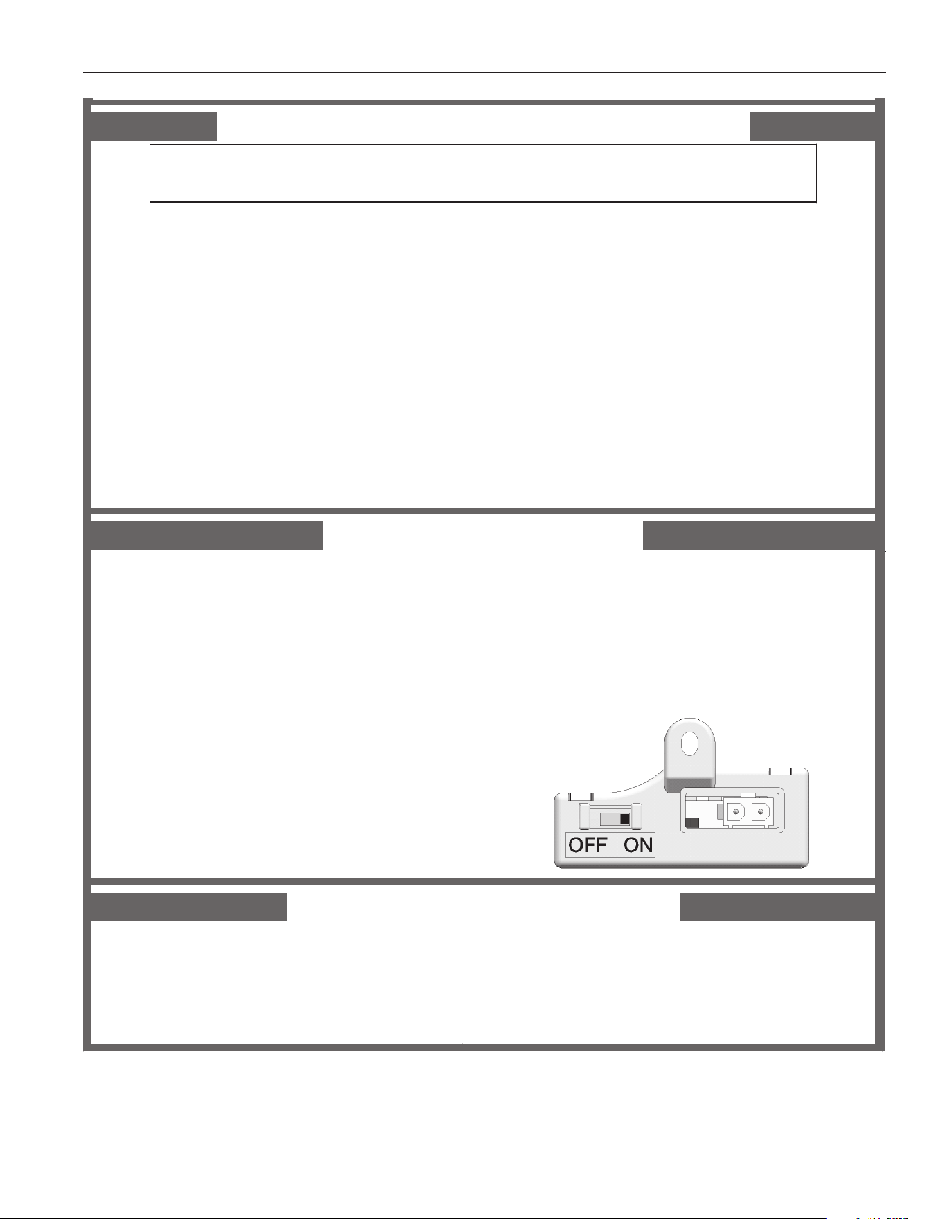
55
FOR YOUR SAFETY READ BEFORE OPERATING
WARNING:
If you do not follow these instructions exactly, a fire or explosion
may result causing property damage, personal injury, or loss of life.
A. This appliance does not have a pilot. It is
equipped with an ignition device which
automatically lights the burner. Do not try
to light the burner by hand.
B. BEFORE OPERATING smell all around
the appliance area for gas. Be sure to
sm ell n ext to the floor because s ome ga s
is heavier than air and will settle on the
floor.
WHAT TO DO IF YOU SMELL GAS
• Do not try to light any appliance.
• Do not touch any electric switch; do
not use any phon e in you r bu ild in g.
• Immediately call your gas supplier from a
neighbor’s phone. Follow the gas supplier’s
instructions.
• If you cannot reach your gas supplier, call
the fir e depa rtm ent.
C. Use only your hand to move the gas control
switch. Never use tools. If the switch will not
move by hand, don’t try to repair it, call a
qualified service technician. Force or attempted
repair may result in a fi re or explosion.
D. Do not use this appliance if any part has been
under water. Immediately call a qualified
servi ce techni cian to inspect the appliance and
to replace any part of the control system and
any gas control which has been under water.
OPERATING INSTRUCTIONS
1. STOP! Read the safety information
above on this label.
2. Set the thermostat to lowest setting.
3. Turn off all electric power to the
appliance.
4. This appliance is equipped with an ignition
device which automatically lights the
burner. Do not try to light the burner by
hand.
5. Remove front door.
6. Move switch to the “OFF” position.
7. Wait five (5) minutes to clear out any gas.
If you then smell gas, STOP! Follow “B”
in the safety information above this label.
If you don’t smell gas, go to next step.
8. Move the switch to the “ON” position.
9. Install fr ont door.
10. Turn on all electric power to appliance.
11. Set thermostat to desired setting.
12. If the appliance will not operate, follow the
instructions “To Tur n Off Gas To Ap pl iance” and
call your service technician or gas supplier.
TO TURN OFF GAS TO APPLIANCE
1. Set the thermostat to lowest setting.
2. Turn off all electric power to the appliance
if service is to be performed.
3. Remove front door.
4. Move the switch to the “OFF” position.
5. Install fr ont door.
LBL 233 9
REV
C
OPERATING INSTRUCTIONS FOR MODELS 150 - 285
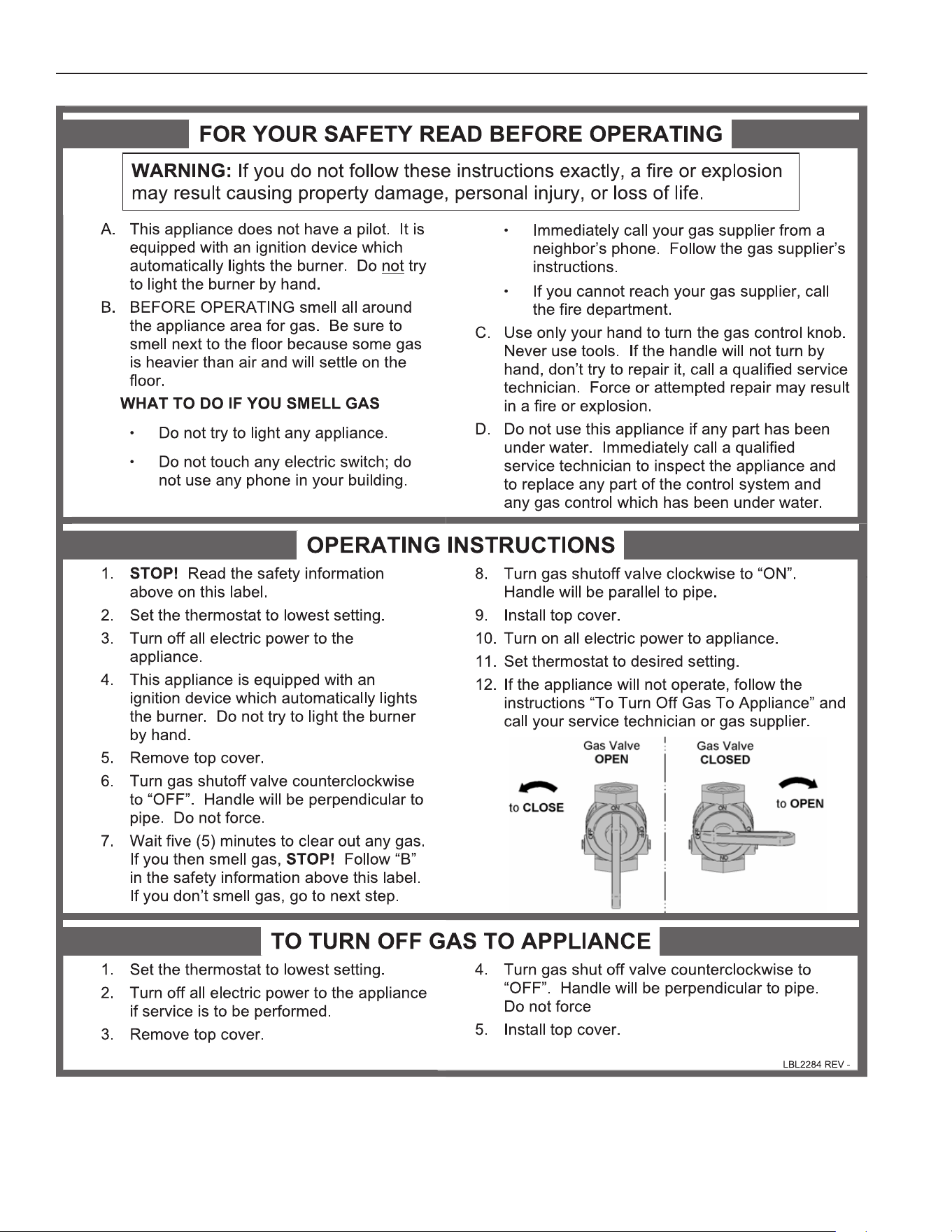
56
OPERATING INSTRUCTIONS FOR MODELS 400 - 800

57
Freeze protection
DO NOT install the water heater in a room likely to freeze.
The following integral feature of the Control Module provides
some protection for the water heater.
• The Control Module provides freeze-up protection as
follows when the water heater water temperature drops
below 45°F:
• Below 45°F, the water heater pump operates constantly.
• Below 37°F, the water heater turns on.
• The water heater and pump will turn off if water heater
water temperature rises above 45°F.
This feature of the Control Module does not eliminate the
possibility of freezing. The installation must still use recognized
design, installation and maintenance practice to prevent freeze
potential for the water heater.
Monitor external limits
Connections are provided on the connection board for external
limits such as fl ow switch, gas pressure switches, and a damper
proving switch. The Control Module will shut off the burner and
inhibit relighting whenever any of these external limits open.
Runtime and alarm outputs
The water heater provides dry contacts for indicating when the
water heater is running, and when it is unable to operate.
Runtime and cycle counting
The control uses a timer to monitor the total hours of burner
operation. The timer monitors the time the water heater is fi ring.
The control uses two (2) ignition counters to monitor the amount
of water heater cycles. The fi rst counter counts all ignitions of the
control. The second counter counts only ignition attempts that
have failed.
Service
This unit can be programmed to access the Contact Name and
Contact Phone parameter for service and maintenance.
WATER HEATER TEMPERATURE REGULATION
Operating temperature (target)
The Control Module senses water temperature and regulates
water heater fi ring and fi ring rate to achieve a target temperature.
The target temperature can be set between 60°F and 190°F.
GENERAL
HOW THE WATER HEATER OPERATES
The XP water heater uses an advanced stainless steel heat
exchanger and electronic control module that allows fully
condensing operation. The blower pulls in air and pushes fl ue
products out of the water heater through the heat exchanger and
fl ue piping. The control module regulates blower speed to control
the water heater fi ring rate. The gas valve senses the amount of
air fl owing into the water heater and allows only the right amount
of gas to fl ow.
CONTROL INPUTS AND OUTPUTS
Tank thermostat / tank sensor
Either of these inputs will tell the water heater to provide heat to
the water tank. If a tank sensor is connected, the Control Module
will ignore the tank thermostat.
0 - 10VDC input (set point or power)
The XP water heater can be controlled by a Building Management
System (BMS) using a 0 - 10 VDC signal. The control can be
confi gured by the installer to use this signal to either control set
point or fi ring rate. This signal can be sent to the heater through
ModBus as well.
TEMPERATURE CONTROL
Modulation
The XP water heater is capable of modulating its fi ring rate from
a minimum of 20% to a maximum of 100%. The fi ring rate is
dictated by the hot water draw and various other temperature
limitations.
Setpoint Adjustment (Economy Mode/Clock)
The controller may be programmed to reduce the DHW set point
during certain times each week. Seven different start and stop
times may be programmed for the DHW Setpoint Adjustment.
Flame current support
To prevent nuisance shutdowns when the water heater is fi ring
at minimum rates, the control will increase fan speed when the
fl ame signal drops too low.
PROTECTION FEATURES
Outlet temperature, fl ue temperature, and temperature rise
limiting
The outlet temperature is monitored by the water heater outlet
temperature sensor. When the outlet temperature exceeds 185°F,
the unit will reduce the fan speed. If the outlet water temperature
exceeds 195°F the control will shut the unit down until it cools off.
The control module monitors the fl ue temperature by a sensor
located in the fl ue exhaust. If the fl ue temperature exceeds
215°F the control will reduce the maximum fan speed. If the fl ue
temperature exceeds 240°F the control will shut the unit down.
The unit will restart automatically once the fl ue temperature
drops 25°F and the minimum off time has expired.
The control monitors the temperature difference between the inlet
and the outlet sensor. If the control determines the temperature
rise is too high, it will either reduce the fi ring rate or shut down
the unit as appropriate.
The unit will restart automatically once the temperature difference
has dropped below the allowable rise and the minimum off time
has expired.
CONTROL SYSTEM OPERATION
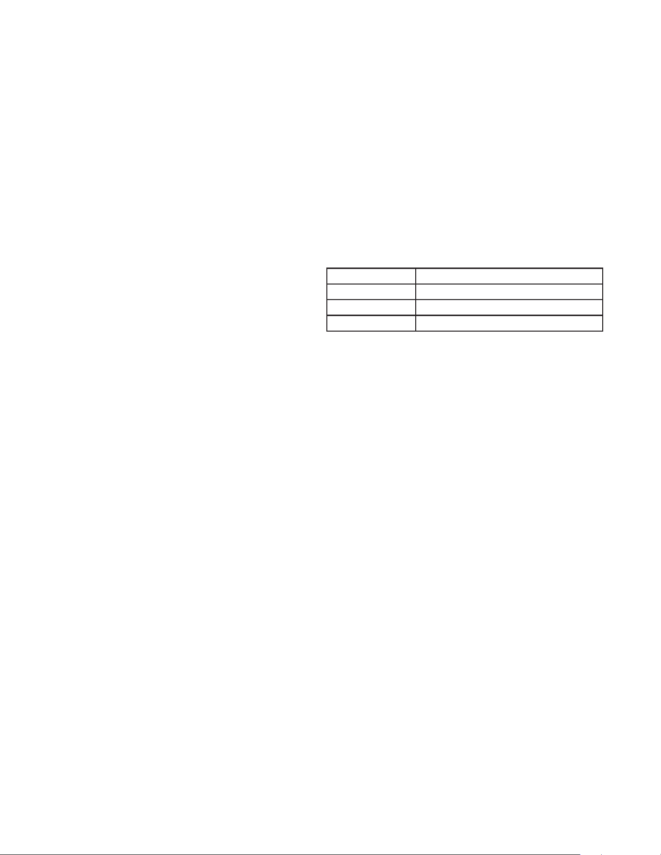
58
Once the Leader water heater receives a call for heat from a tank
sensor, BMS or Modbus, the control will determine what the set
point will be. A fi xed temperature set point can be programmed
into the control. See page 57 of this manual to program the set
point. If the water temperature at the tank is less than the set
point - differential, then the control will initiate a call for heat on
the Lead/Lag (see the XP Water Heater Service Handbook for an
explanation of the differential). The Leader will energize the lead
water heater on the Lead/Lag. For a new startup this will be the
Leader water heater.
Sequence of the Lead/Lag
To equalize the runtime of all water heaters on the Lead/Lag, the
fi ring sequence will automatically be changed at set intervals. For
the fi rst 24 hours after initializing the Lead/Lag, the sequence will
be changed every hour. After that the sequence will be changed
once every 24 hours. The switching on/off sequence will be as
follows:
Table 26. Sequence of the Lead/Lag
TIME SWITCHING ON SEQUENCE
Start L-M1-M2-M3-M4-M5-M6-M7
+ 1 hour M1-M2-M3-M4-M5-M6-M7-L
+ 2 hours M2-M3-M4-M5-M6-M7-L-M1
If a water heater locks out, it will automatically be given the
lowest priority for the rest of that 24 hour period.
Setpoint Adjustment operation with Lead/Lag
Setpoint Adjustment operation of the water heaters within the
Lead/Lag is available. Programming of the Setpoint Adjustment
will be done through the Leader water heater. Refer to the XP
Water Heater Service Handbook for information regarding
Setpoint Adjustment.
ACCESS MODES
User
The user can adjust tank target temperatures by touching the
MENU and accessing the Temperature Settings parameters on
the UIM. The date and time, and the temperature units can also
be changed.
Installer
Most parameters are available only to the installer, accessible by
entering the installer password, see the XP Water Heater Service
Handbook.
SAVING PARAMETERS
To save parameters and exit programming:
Press ACCEPT on the display after parameter settings.
To enter a parameter and continue programming:
Press ACCEPT after entering the values and return to the
parameter listings. Press BACK to return to the MENU listings.
See the XP Water Heater Service Handbook for a detailed
description of parameters and access modes.
High limit operations
The XP water heater is equipped with a fi xed manual reset hight
limit and an adjustable manual reset high limit. The automatic
reset high limit has a set point of 200°F and the manual reset
high limit has a maximum set point of 210°F.
When the outlet temperature exceeds 200°F, the automatic high
limit action occurs. The water heater shuts down until the outlet
water temperature cools below 190°F, and a 60 second timer
has expired. If the outlet temperature continues to increase, the
manual reset high limit action will occur at 210°F.
High Limit Test procedure
1. Turn ON the main power to the water heater by placing the
ON/OFF switch in the ON position.
2. From the Touch Screen Display, access MENU to reach the
Temperatures parameters.
3. Select the Manual Reset High Limit parameter to access the
MIN & MAX settings..
4. Using the "-" button, decrease the set point of the MRHL
to below the current outlet temperature (or to its minimum
setting, whichever is higher).
5. Press the ACCEPT button to upload the new values to the
control.
6. If the current outlet temperature is above the new MRHL set
point, the MRHL will function causing water heater lockout. If
this occurs, skip to Step 9.
7. If the current outlet temperature is below the new MRHL place
the water heater into Service Mode. In Service Mode, the
water heater will fi re at ignition speed and will then modulate
up to full fi re.
8. Once the outlet temperature rises up to the MRHL set point,
the MRHL will function, causing the water heater to shut
down and lock out.
9. Repeat Steps 2 and 3.
10. Set the MRHL to the appropriate set point by using the "+" or
"-" buttons and then press ACCEPT..
11. Press the RESET button to clear the lockout.
12. If needed, exit Service Mode.
Low water cutoff protection
1. The Control Module uses temperature sensing of both
supply and return areas of the heat exchanger. If the fl ow
rate is too low or the outlet temperature too high, the control
module modulates and shuts the water heater down. This
ensures water heater shutdown in the event of low water or
low fl ow conditions.
2. Some codes and jurisdiction may accept these integral
features of the control in lieu of requiring an additional
limit control or low water cutoff. Consult local jurisdiction to
determine. A low water cutoff is available from the factory
(100173646).
LEAD/LAG
When multiple water heaters are installed, they can be wired
together in a Lead/Lag sequence. A maximum of eight water
heaters can be controlled from a single control. In this application
one water heater would be designated as the Leader control
and all others would be designated as Member controls. The
Leader control can be programmed to use Lead/Lag or Effi ciency
Optimization control methods.
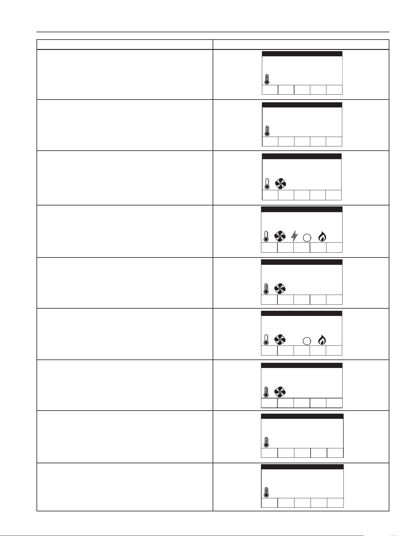
59
SEQUENCE OF OPERATION
OPERATION TOUCH SCREEN DISPLAY
1. The control will turn on the water heater pump (always
ON except in Setpoint Adjustment). The fl ow switch and/or
LWCO must close.
2. The control turns on power to the damper relay. The damper
proving switch, air pressure switch, and blocked drain switch
must close.
3. The control starts the prepurge cycle.
4. The control starts the trial for ignition by energizing the spark
electrode and opening the gas valve.
5. If fl ame is not detected after the sparking ends, the control
will perform a postpurge, then start another prepurge cycle
and try to light the burner again. On the 500 and larger
models, the control will lock out if this second attempt fails.
On the 400 and smaller models, the control will perform a
total of 4 attempts before locking out.
6. If fl ame is detected, it holds the fi ring rate steady for a few
seconds to let the fl ame stabilize, then it begins to modulate
the fi ring rate based on a set point or some other command
(such as a 0-10V BMS signal).
7. Once the call for heat is satisfi ed, the control will de-energize
the gas valve. The blower will continue to run during the
postpurge.
8. The water heater pump will continue to run for its respective
pump delay time before turning off. A 60 second anti-cycle
period will start, which will delay any new call for heat until
it times out.
9. In Standby, ready to start a new cycle.
Tank Temperature 90°F
Operating Setpoint 93°F
Status: Pre-Purge
HELPDISABLE
A. O. Smith XP
MENU
Tank Temperature 90°F
Operating Setpoint 93°F
Status: Ignition
HELPDISABLE
A. O. Smith XP
MENU
OFF
GAS
O
N
Tank Temperature 90°F
Operating Setpoint 93°F
Status: Post-Purge
HELPDISABLE
A. O. Smith XP
MENU
Tank Temperature 90°F
Operating Setpoint 93°F
Status: Heating
HELPDISABLE
A. O. Smith XP
MENU
OFF
GAS
O
N
Tank Temperature 92°F
Operating Setpoint 93°F
Status: Short Cycling
HELPDISABLE
A. O. Smith XP
MENU
Tank Temperature 92°F
Operating Setpoint 93°F
Status: Standby
HELPDISABLE
A. O. Smith XP
MENU
Tank Temperature 92°F
Operating Setpoint 93°F
Status: Standby
HELPDISABLE
A. O. Smith XP
MENU
Tank Temperature 92°F
Operating Setpoint 93°F
Status: Standby
HELPDISABLE
A. O. Smith XP
MENU
Tank Temperature 90°F
Operating Setpoint 93°F
Status: Post-Purge
HELPDISABLE
A. O. Smith XP
MENU
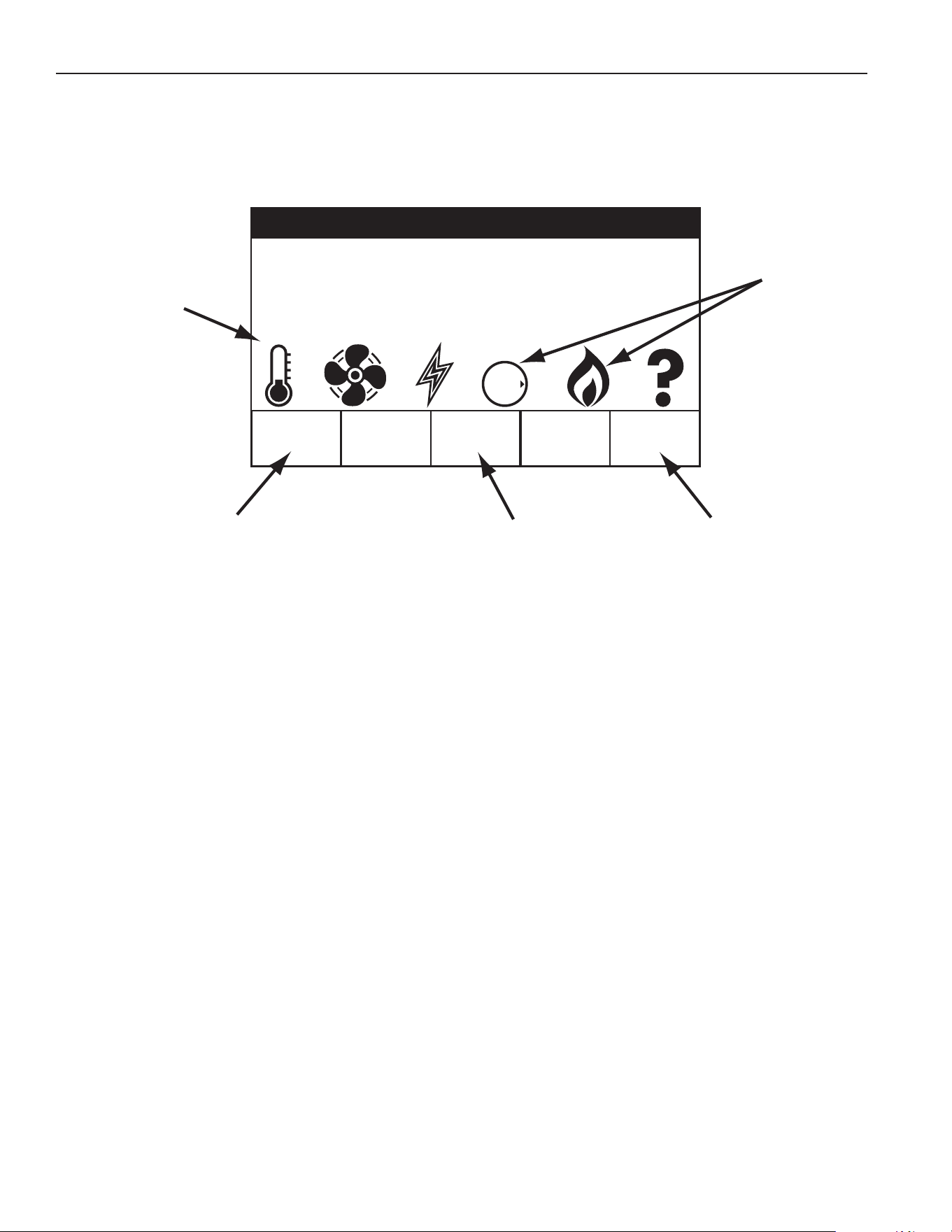
60
USER INTERFACE MODULE (UIM)/ TOUCH SCREEN DISPLAY
Tank Temperature 71°F
Operating Setpoint 184°F
Status: Ignition
HELPDISABLE
A. O. Smith XP
MENU
OFF
GAS
O
N
LCD Touch
Screen Display
Status Icons
Main Menu Help MenuEnable / Disable Button
Figure 75. User Interface Module (UIM)/ Touch Screen Display
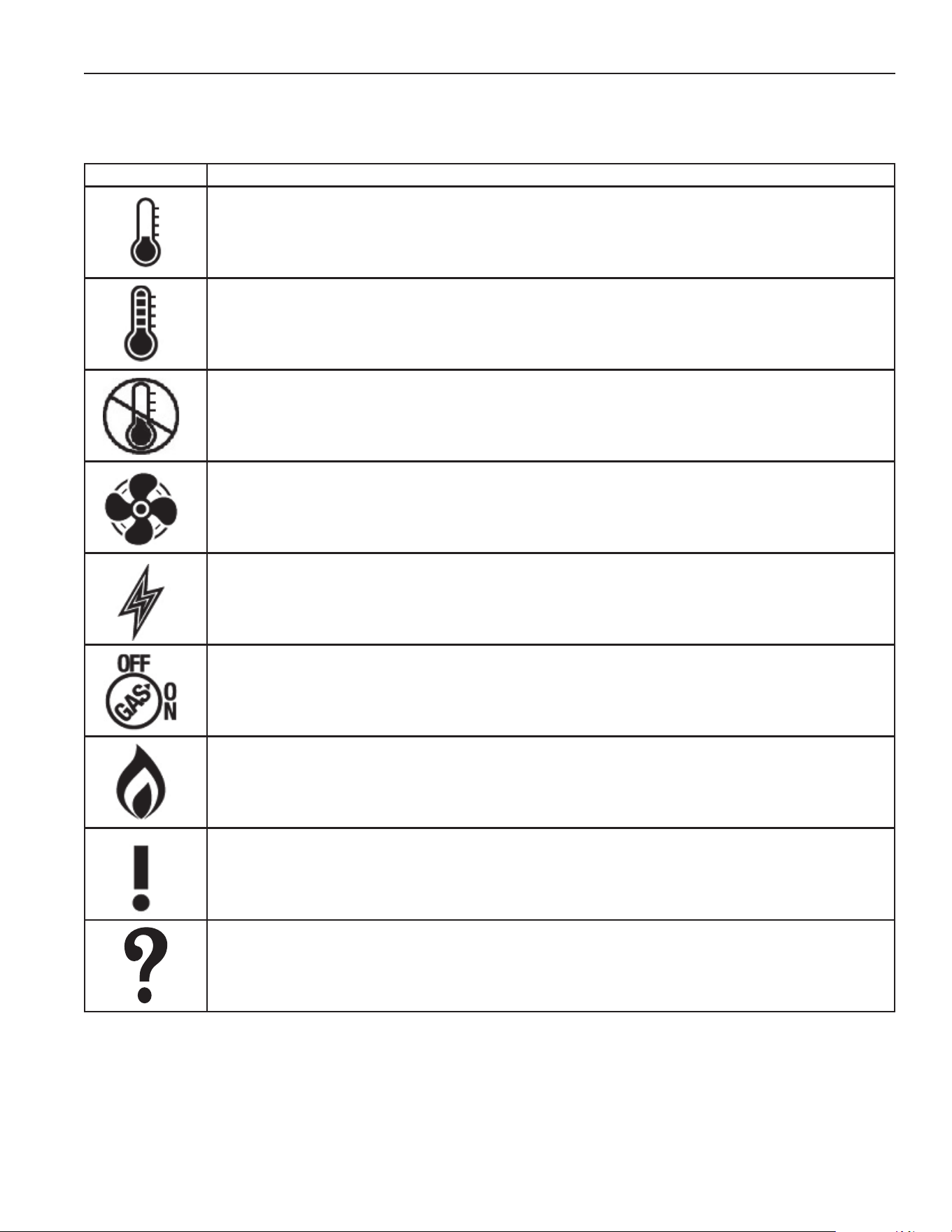
61
STATUS ICONS
The Status Icons are displayed on the Desktop screen and convey operational and diagnostic information. The icons are described in
the table below. Ensure the water heater is properly grounded. Flame sensing requires an adequate earth ground. If the water heater
is not properly grounded it will cause ignition failure.
TABLE 27
Icon Description
Water temperature in the tank has fallen. 'Mercury' increases as tank temperature rises.
Shaded area of the animated thermometer icon will rise and fall in response to water temperature in the storage tank as
sensed from the Upper and Lower Temperature Probes..
Water temperature in the tank has reached the Operating Setpoint.
The control system enters the Standby mode.
The control system is unable to initiate a heating cycle. When 'shutdown', the display will read 'Status: Water Heating
Disabled'.
This will happen whenever a Fault condition is detected by the control system or when the Enable/Disable switch on the
display is in Disable position or Building Management system Enable/Disable circuit is an open circuit. Display will read
"Status: Water Heating Disabled".
The Combustion Blower is being energized.
The Spark Igniter is being energized.
The 24VAC gas valve has been energized.
The control system has sensed fl ame at the burner from the fl ame sensor.
See the Sequence of Operation on Page 56.
The control system has declared a Fault condition. The control system must be inspected/serviced by a Qualifi ed Service
Technician. Fault message details can be viewed in the Current Fault menu. Heating operation is disabled (lock out) until
the condition that caused the Fault is corrected. Power to the water heater must be cycled off and on at the breaker to reset
the control system.
NOTE: Cycling power will not reset the control system if the condition that caused the Fault has not been corrected.
The control system has declared an Alert condition. The control system must be inspected/serviced by a Qualifi ed Service
Technician. The water heater will continue to operate during an Alert condition.
62
OPERATING STATES
The current operational state of the water heater is displayed on the User Interface Module (UIM) screen as the "Status." The
common operational states are described in the table below. Ensure the water heater is properly grounded. Flame sensing requires
an adequate earth ground. If the water heater is not properly grounded it will cause ignition failure.
TABLE 28
State Description
Standby The unit has not received a call for heat from a remote thermostat nor has it received a call for heat from a DHW thermostat.
Input Verifi cation The unit has begun a burn cycle and is checking all safety circuits.
Pre-Purge The unit has initiated a pre-purge period on a call for heat.
Inter-purge The combustion chamber is energized to fl ush residual fl ue gas from the combustion chamber after a failed ignition attempt.
Heating The unit has fi red and is running.
Post-purge The call for heat has been satisfi ed and the unit runs the blower for an additional post-purge period to clear the combustion
chamber and vent system of residual fl ue products.
Enable/ Disable The unit is in On/Off position.
Setpoint Met The controlled temperature has exceeded its set point and its offset.
Fault The main control board has detected an internal fault.
Alert The unit has detected a condition that has temporarily interrupted the current call for heat.
CONTROL SYSTEM MENUS
From the UIM screen touching the "Menu" on the display will show the "Main Menu". This is where all control system menus are
located. The table below describes the control system menus.
TABLE 29
Menu Description
Temperatures Most commonly accessed menu. Contains the Operating Setpoint and Differential user settings.
Heater Status This menus displays the current state of all pressure switches and the ECO (open/closed). The on/off status of the
Combustion Blower, gas valve, Spark Igniter, fl ame sensor and other monitored water heater components are displayed
in this menu.
Display Settings Temperature units (°F or °C), the LCD appearance (brightness/contrast) and backlight delay user adjustable settings
are located in this menu.
Heater Information Elapsed time of operation, total heating cycle time, heating cycle count, heating on time along with UIM and CCB
software revisions can be viewed in this menu.
Current Fault Displays any current Alert or Fault messages.
Fault History This control system menu retains a list of the last nine (9) Fault and Alert messages with a time stamp. The newest
event will replace the oldest. Faults will clear after 30 days.
Fault Occurrence This control system menu retains a running total of how many times each Fault condition has occurred since the water
heater was fi rst installed. The data does not clear and cannot be reset.
Service The Service Menu displays service & maintenance parameters such as the last service date, contact information in
case of any service procedures and also the gives access to Service Mode operation.
Circulation Pumps The Circulation Pumps menu contains settings for the DHW Pump Delay, Freeze Protection, and Anti-Seize parameters.
Building Management The Building Management menu contains parameters for operating the unit with 0 – 10V signal.
Lead/ Lag The Lead/Lag menu contains parameters used to connect multiple hot water heaters together.
Economy Mode/ Clock The Economy Mode/Clock menu allows the user to set the time and date on the hot water heater, as well as schedule
periods to run at lower temperatures.
Short Cycling The Short Cycling menu contains parameters that prevent the heater from starting a cycle too quickly after it has
fi nished a previous call for heat.
Restore Factory Defaults This control system feature allows the user to restore control system user settings to their factory default settings.
Display Settings preferences ARE NOT changed when factory defaults are restored.
Help Screens Text based operational and user information explaining how to change user settings, navigate the control system menus
and icon descriptions.
63
MAINTENANCE
MAINTENANCE SCHEDULES
SERVICE TECHNICIAN
(SEE THE FOLLOWING PAGES FOR INSTRUCTIONS)
ANNUAL
General:
• Address reported problems
• Inspect interior; clean and vacuum
if necessary;
• Clean condensate trap and fi ll with
fresh water
• Check for leaks (water, gas, fl ue,
condensate)
• Verify fl ue and air lines in good
condition and sealed tight
• Check system water pressure
system piping/expansion tank
• Check control settings
• Check ignition and fl ame sense
electrodes (clean off any deposits;
clean and reposition)
• Check wiring and connections
• Perform start-up checkout and
performance verifi cation per Start
Up section of this manual.
• Flame inspection (stable, uniform)
• Flame signal (at least 10
microamps at high fi re)
• Clean the heat exchanger if fl ue
temperature is more than 54°F
above return water temperature.
• Check Delta T (Temperature
Rise). Refer to Table 22 on Page
37.
If combustion or performance indicate
need:
• Clean heat exchanger
• Remove and clean burner using
compressed air only
• Clean the blower wheel
OWNER MAINTENANCE
DAILY • Check water heater area
MONTHLY
• Check vent piping
• Check air piping
• Check air and vent termination
screens
• Check T & P Relief Valve
• Check condensate drain system
• Check automatic air vents
• Check Delta T (Temperature Rise)
• Remove debris from Y-strainer per
manufacturer's instructions
EVERY 6
MONTHS
• Check water heater piping (gas
and water) for leaks
• Operate T & P Relief Valve
• Check water chemistry
Table 30. Service and Maintenance Schedules
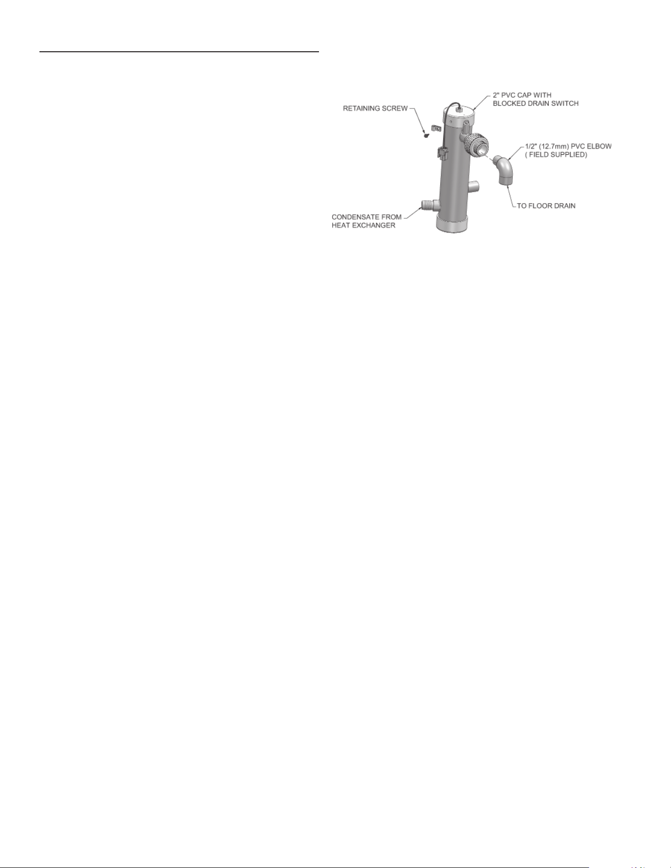
64
MAINTENANCE
Follow the service and maintenance procedures given throughout
this manual and in component literature shipped with the water
heater. Failure to perform the service and maintenance could
result in damage to the water heater or system. Failure to follow
the directions in this manual and component literature could
result in severe personal injury, death, or substantial property
damage.
The water heater should be inspected annually only by a qualifi ed
service technician. In addition, the maintenance and care of
the water heater designated in Table 30 and explained on the
following pages must be performed to assure maximum water
heater effi ciency and reliability. Failure to service and maintain
the water heater and system could result in equipment failure.
Electrical shock hazard – Turn off power to the water heater
before any service operation on the water heater except as noted
otherwise in this instruction manual. Failure to turn off electrical
power could result in electrical shock, causing severe personal
injury or death.
REVIEW WITH OWNER
1. Emphasize the need to perform the maintenance schedule
specifi ed in this manual.
2. Remind the owner of the need to call a qualifi ed service
technician should the water heater or system exhibit any
unusual behavior.
3. Remind the owner to follow the proper shutdown procedure
and to schedule an annual maintenance
4. Inspect any problems reported by the owner and correct
before proceeding.
INSPECT WATER HEATER AREA
1. Verify that water heater area is free of any combustible
materials, gasoline and other fl ammable vapors and liquids.
2. Verify that air intake area is free of any of the contaminants
listed on Page 14. If any of these are present in the water
heater intake air vicinity, they must be removed. If they
cannot be removed, reinstall the air and vent lines per this
manual and the XP water heater Service Handbook.
INSPECT WATER HEATER INTERIOR
1. Remove the front access cover and inspect the interior of
the water heater.
2. Vacuum any sediment from inside the water heater and
components. Remove any obstructions.
CLEAN CONDENSATE TRAP
1. Inspect the condensate drain line, condensate PVC fi ttings,
and condensate trap.
2. Remove the PVC cap retaining screw from the PVC cap
(Figure 76).
3. Remove the 2 inch PVC cap with the switch located at the
top of the trap (Figure 76).
4. Remove any sediment in the trap.
5. Fill with fresh water until the water begins to pour out of the
drain.
6. Replace the cap. Press the cap onto the trap until the cap
makes contact with the drain.
7. Replace the retaining screw.
Figure 76. Condensate Trap
The condensate trap must be fi lled with water during all times
of water heater operation to avoid fl ue gas emission from the
condensate drain line. Failure to fi ll the trap could result in severe
personal injury or death.
CHECK ALL PIPING FOR LEAKS
Eliminate all system or water heater leaks. Leaking water may
cause severe property damage.
1. Inspect all water and gas piping and verify to be leak free.
2. Look for signs of leaking lines and correct any problems
found.
3. Check gas line using the procedure found in Gas Connections
section on Page 42.
FLUE VENT SYSTEM AND AIR PIPING
1. Visually inspect the entire fl ue gas venting system and air
piping for blockage, deterioration or leakage. Repair any
joints that show signs of leakage. Verify that air inlet pipe is
connected and properly sealed.
2. Verify that water heater vent discharge and air intake are
clean and free of obstructions.
Failure to inspect for the above conditions and have them
repaired can result in severe personal injury or death.
CHECK WATER SYSTEM
1. Verify all system components are correctly installed and
operational.
2. Watch the system pressure as the water heater heats up
(during testing) to ensure pressure does not rise too high.
Excessive pressure rise indicates expansion tank sizing or
performance problem.
CHECK EXPANSION TANK
1. Expansion tanks provide space for water to move in and out
as the heating system water expands due to temperature
increase or contracts as the water cools. Tanks may be
open, closed or diaphragm or bladder type. See Water
Heater Installation section on Page 36 for suggested best
location of expansion tanks and air eliminators.
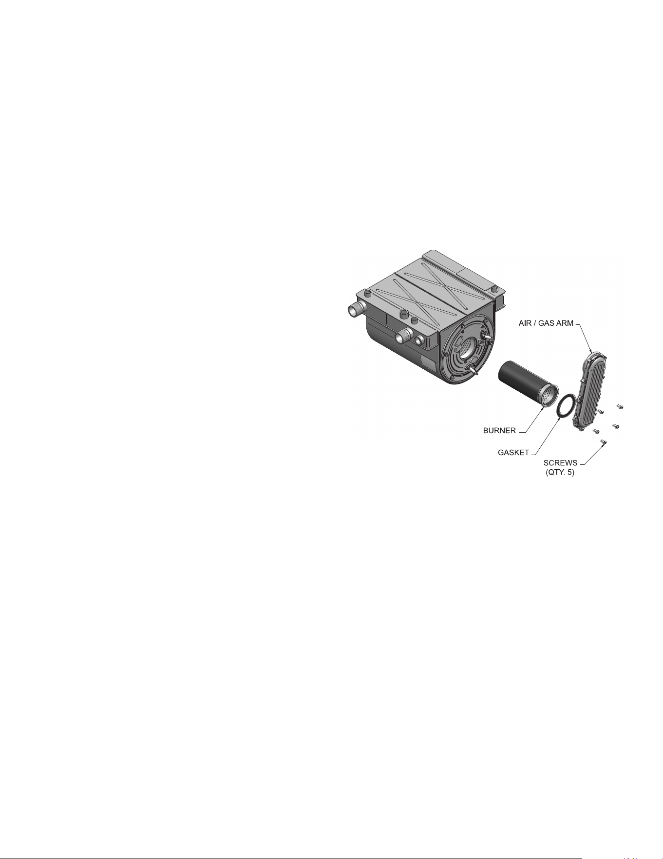
65
CHECK WATER HEATER T & P RELIEF VALVE
1. Inspect the T & P Relief Valve and lift the lever to verify fl ow.
Before operating any T & P Relief Valve, ensure that it is
piped with its discharge in a safe area to avoid severe scald
potential. Read System Piping section on Page 36 before
proceeding further.
Safety T & P Relief Valves should be re-inspected AT LEAST
ONCE EVERY THREE YEARS, by a licensed plumbing
contractor or authorized inspection agency, to ensure that the
product has not been affected by corrosive water conditions and
to ensure that the valve and discharge line have not been altered
or tampered with illegally. Certain naturally occurring conditions
may corrode the valve or its components over time, rendering the
valve inoperative. Such conditions are not detectable unless the
valve and its components are physically removed and inspected.
This inspection must only be conducted by a qualifi ed service
technician. Failure to re-inspect the water heater T & P Relief
Valve as directed could result in unsafe pressure buildup, which
can result in severe personal injury, death, or substantial property
damage.
Following installation, the valve lever must be operated AT
LEAST ONCE A YEAR to ensure that waterways are clear.
Certain naturally occurring mineral deposits may adhere to the
valve, rendering it inoperative. When manually operating the
lever, water will discharge and precautions must be taken to
avoid contact with hot water and to avoid water damage. Before
operating lever, check to see that a discharge line is connected
to this valve directing the fl ow of hot water from the valve to a
proper place of disposal. Otherwise severe personal injury may
result. If no water fl ows, valve is inoperative. Shut down the water
heater until a new T & P Relief Valve has been installed.
2. After following the above warning directions, if the T & P
Relief Valve weeps or will not seat properly, replace the T
& P Relief Valve. Ensure that the reason for T & P Relief
Valve weeping is the valve and not over-pressurization
of the system due to the lack of a thermal expansion tank
waterlogging or undersizing.
INSPECT IGNITION AND FLAME SENSE ELECTRODES
1. Remove the ignition and fl ame sense electrodes from the
water heater heat exchanger access cover.
2. Remove any deposits accumulated on the ignition/fl ame
sense electrode. If the electrodes cannot be cleaned
satisfactorily, replace with new ones.
3. Replace ignition/fl ame sense electrode, making sure gasket
is in good condition and correctly positioned.
CHECK IGNITION GROUND WIRING
1. Inspect water heater ground wire from the heat exchanger
access cover to ground terminal strip.
2. Verify all wiring is in good condition and securely attached.
3. Check ground continuity of wiring using continuity meter.
4. Replace ground wires if ground continuity is not satisfactory.
CHECK ALL WATER HEATER WIRING
1. Inspect all water heater wiring, making sure wires are in
good condition and securely attached.
CHECK CONTROL SETTINGS
1. Use the UIM control display to access MENU and check
all parameter settings. Adjust settings if necessary. Refer
to the XP Water Heater Service Handbook for adjustment
procedures.
2. Check settings of external limit controls (if any) and adjust
if necessary.
PERFORM START-UP AND CHECKS
1. Start water heater and perform checks and tests specifi ed in
Start Up section of this manual.
CHECK BURNER FLAME
1. Inspect fl ame through observation window.
2. If the fl ame is unsatisfactory at either high fi re or low fi re,
turn off water heater and allow water heater to cool down.
Remove the burner (see Figure 77 below) and clean it
thoroughly using a vacuum cleaner or compressed air. Do
not use compressed air to clean burner if performed inside
a building.
3. When replacing the burner, ensure gasket is in good
condition and positioned correctly (Figure 77).
CHECK FLAME SIGNAL
1. At high fi re the fl ame signal shown on the display should be
at least 10 microamps.
2. A lower fl ame signal may indicate a fouled or damaged fl ame
sense electrode. If cleaning the fl ame sense electrode does
not improve, ground wiring is in good condition, and ground
continuity is satisfactory, replace the fl ame sense electrode.
3. See Troubleshooting section in the XP Water Heater Service
Handbook for other procedures to deal with low fl ame signal..
Figure 77. Burner Assembly
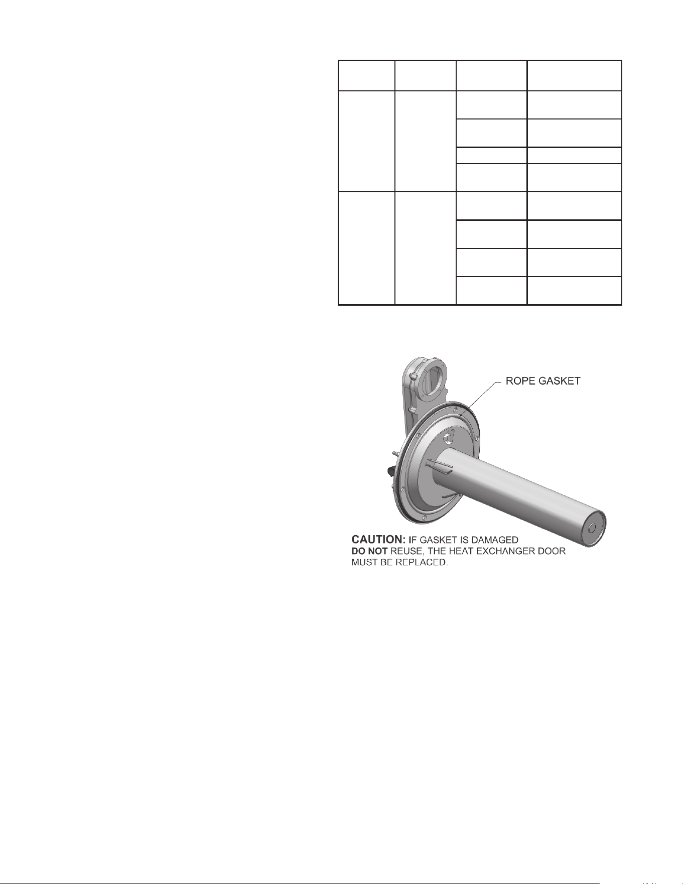
66
CLEANING HEAT EXCHANGER
For recommended materials; including brush, appropriate
extension(s), refractory cover, and detailed instructions see
Table 31 - Heat Exchanger Cleaning Kits.
1. Shut down water heater:
• Follow the “To Turn Off Gas to Appliance” instructions for
the water heater in Start Up section.
• Do not drain the water heater unless it will be exposed to
freezing temperatures. If using freeze prevention fl uid in
system, do not drain.
2. Allow time for the water heater to cool to room temperature
if it has been fi ring.
3. Remove the nuts securing the heat exchanger access cover
to the heat exchanger and set aside.
4. Remove the heat exchanger access cover, burner, and gas/
air arm assembly.
The water heater contains ceramic fi ber materials. Use care
when handling these materials per instructions in the Service
Handbook. Failure to comply could result in severe personal
injury.
5. Remove the condensate hose from the heat exchanger end.
Connect a fi eld supplied 3/4" diameter hose to a drain pan.
Using fi eld supplied means, cover the refractory in the back
of the combustion chamber of the heat exchanger.
6. Use a vacuum cleaner to remove any accumulation on the
water heater heating surfaces. Do not use any solvent.
7. Brush the heat exchanger while dry using a nylon bristle
brush. Caution: DO NOT use a metal brush. Re-vacuum the
heat exchanger after cleaning.
8. Finish cleaning using a clean cloth dampened with warm
water. Rinse out debris with a low pressure water supply.
9. Allow the heat exchanger to thoroughly dry.
10. Remove the fi eld supplied rear refractory cover from the
back of the combustion chamber of the heat exchanger and
reassemble.
11. Close isolation valves on piping to isolate water heater from
system. Attach a hose to the water heater drain and fl ush
water heater thoroughly with clean water by using purging
valves to allow water to fl ow through the water make-up line
to the water heater.
12. Perform start-up and check-out procedures in the Check
Flame and Combustion - on Pages 50 and 51 of this manual.
13. Replace the access cover and restore water heater to
operation.
. Heat Exchanger Cleaning Kits
MODEL KIT
NUMBER
PART
NUMBER
COMPONENT
DESCRIPTION
150 - 400 100274672
100140243 Rear Refractory
Cover
100162565* Nylon 4" Wheel
Brush*
100162566 3mm Allen Wrench
100162568 1/4" x 24" Drill
Extension
500 - 800 100274673
100140243 Rear Refractory
Cover
100162565* Nylon 4" Wheel
Brush*
100162567 1/4" x 12" Drill
Extension
100162568 1/4" x 24" Drill
Extension
NOTE: * Do NOT use a metal brush. Only use the kit provided
brush or an equivalent replacement nylon brush.
Figure 78. Rope Gasket - Heat Exchanger Door
NOTE: Rope gasket is intended for sealing combustion (see
Figure 78). If gasket is damaged DO NOT reuse, the heat
exchanger door must be replaced. Consult factory for replacement
heat exchanger door (Kit 100274674 and 100274675).
CHECK DELTA T
1. Check Table 22 on Page 37 for Delta T reference.
OILED BEARING CIRCULATORS
1. The circulator shipped with the XP water heater is water-
lubricated. No oiling is required.
2. Check other circulators in the system. Oil any circulators
requiring oil, following circulator manufacturer’s instructions.
Over-oiling will damage the circulator.
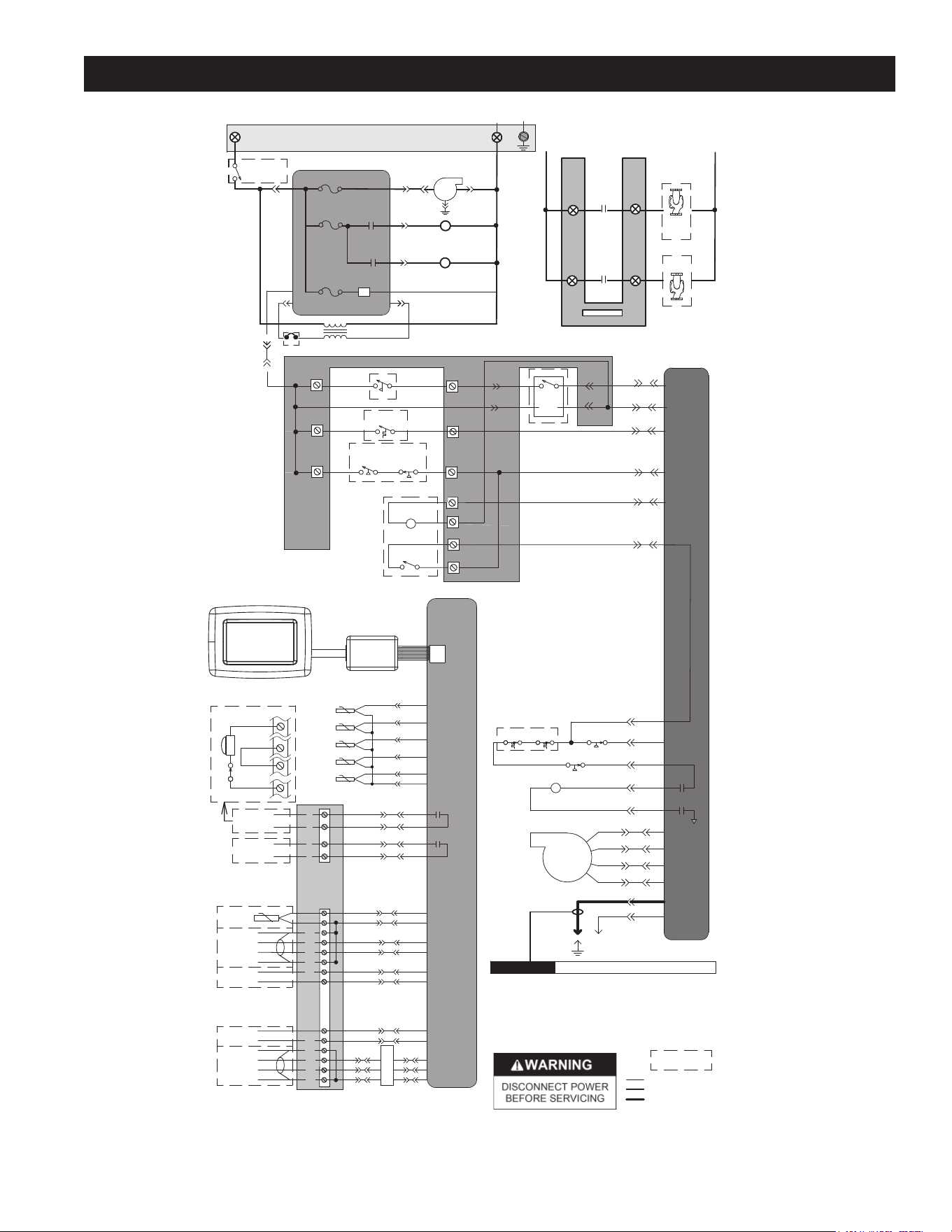
67
WIRING DIAGRAMS
BOX DEPICTS
OPTIONAL ITEMS
LADDER DIAGRAM
100273400 REV. A
INTEGRATED
CONTROL
X2-1
GAS VALVE
GAS VALVE
RELAY
X5-7
X5-16
X5-8
X5-15
1
2
4
5
TR2
X1-7
FLAME ROD
SPARK
ROD
BLOWER
CONNECTION
BOARD
INLET
SENSOR
OPERATING
SENSOR
FLUE
SENSOR
INTEGRATED
CONTROL
RUN-TIME
CONTACTS
RIBBON CABLE
USER INTERFACE MODULE (UIM)
X7
TANK
SENSOR
0-10V
+
-
CASCADE
A
B
SHIELD
SHIELD
13
6
2
1
SILENCING
SWITCH
ALARM
BELL
S4
BMS
CN6
X6
CN6
X6
CN5-2
X4-6
CN5-9
X4-13
CN5-1
X4-7
CN5-8
X4-14
CN6
X6
CN6
X6
HIGH LIMIT
SENSOR
FLUE
SENSOR
X5-4
X5-12
X5-5
X5-13
X5-14
X5-6
0-10V
+
-
RATE
OUT
IN
MODBUS
A
B
SHIELD
SHIELD
CN6
X6
CN8-1
X6-1
CN8-2
X6-2
CN8-3 X6-3
X4-1
X9-2
X4-2
X9-1
X4-3
X9-3
S2
S1a
S1b
S3a
S3b
16
17
19
20
21
22
23
24
25
26
27
28
29
30
3
4
1
2
ALARM
CONTACTS
CN6
X6
M
O
D
B
U
S
CN6
X6
CN6
X6
X2-2
NOTES:
1. Where possible, switches are shown without utilities (gas, water or
electricity) connected to the unit. As such, actual switch states may
vary from those shown on diagrams depending upon whether utilities
are connected or a fault condition is present.
2. See wiring diagram for additional notes.
LOW VOLTAGE
120 VAC
HIGH VOLTAGE
CN5-5
X4-3
HIGH VOLTAGE SPARK LEADCAUTION
X5-2
X5-11
X5-10
AIR PRESSURE SWITCH
BLOCKED
DRAIN SWITCH
XWH 285-800 ONLY
CN5-12
CN5-11
X4-10
X4-11
LOW GAS
PRESSURE
SWITCH
HIGH GAS
PRESSURE
SWITCH
LOUVER
RELAY COIL
24VAC
LOUVER
PROVING SWITCH
CN5-4
X4-4
CN5-3
X4-5
LWCO
TANK
THERMOSTAT
11
CN5-10
X4-12
CN5-14 X4-8
12
CN7-3
CN7-2
CN7-4
CN7-1
24 VAC
9
6
7
14
13
13
8
7
6
5
10
9
CONNECTION BOARD
120 VAC
24 VAC
120VAC
ON / OFF
SWITCH
X1-6
F2
3.15A
F1
5A
INTEGRATED CONTROL
JUNCTION BOX
X1-1
BUILDING
RECIRC PUMP
RELAY
DHW PUMP
RELAY
24V DC
SUPPLY
F3
.8A
X5-1
X5-9
XWH 800
ONLY
X4-3
X1-3
X1-2
TERMINAL STRIP
120V SUPPLY "N"
3.5A
3
BLOWER
21
BUILDING
RECIRC
PUMP
DHW
PUMP
BUILDING
RECIRC PUMP
RELAY
DHW PUMP
RELAY
NEUTRAL
GROUND
TERMINAL STRIP
120V SUPPLY "L"
L
IN
BUILDING
RECIRC PUMP
CONTACTS
DHW PUMP
CONTACTS
L
OUT
FLOW
SWITCH
JUNCTION BOX
XWH MODELS ONLY
O-TEMP
HEX SW
DOOR TEMP
SW
Figure 79. Ladder Diagram
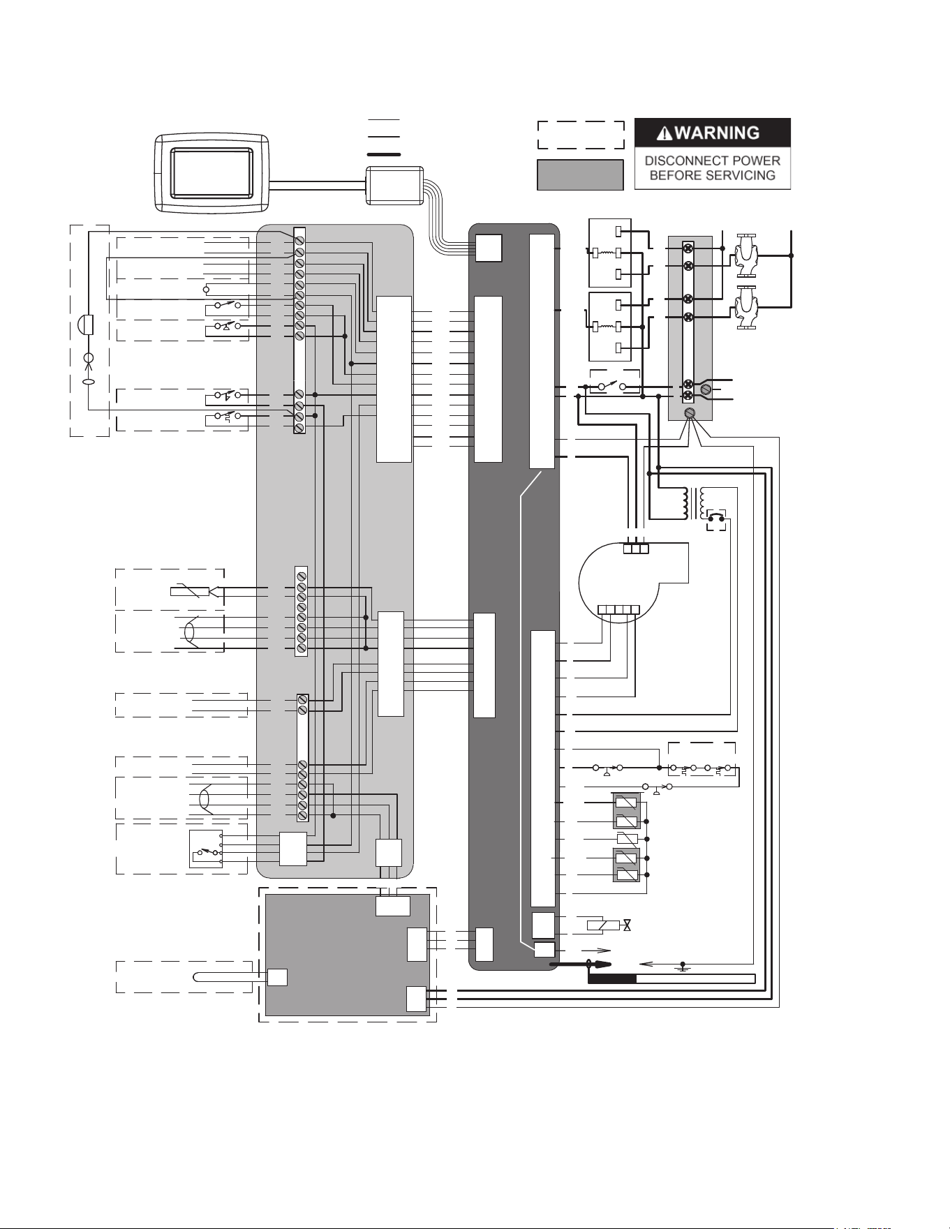
68
X1-7
ON/OFF SWITCH
1
2
3 4
5
G
R
R W
R
T
W
BK
Y
BL
BLOWER
-T
HIGH LIMIT SENSOR S1b
OPERATING SENSOR S1a
INLET SENSOR S2
FLUE SENSOR S3a
FLUE SENSOR S3b
INTEGRATED
CONTROL
BK
Y
GAS VALVE
@24VAC
SPARK
ROD
TRANSFORMER
TR2
G
HIGH VOLTAGE SPARK LEADCAUTION
FLAME SENSOR
ALARM
CONTACTS
RUN-TIME
CONTACTS
24 VAC LOUVER
RELAY COIL
LOUVER
PROVING SWITCH
GAS PRESSURE
SWITCH
FLOW
SWITCH
TANK
THERMOSTAT
11
12
13
14
TANK
SENSOR
CASCADE
A
B
SHIELD
SHIELD
0-10V
+
-
BMS
IN
0-10V
+
-
RATE
OUT
MODBUS
OPTION
A
B
SHIELD
SHIELD
LOW
WATER
CUT-OFF
24 VAC
COM
P/BK
Y
W/R
1
2
3
4
5
6
7
8
9
10
15
16
17
18
19
20
21
22
CN7-1
CN7-2
CN7-3
CN7-4
CN5-1
CN5-8
CN5-2
CN5-9
CN5-3
CN5-10
CN5-11
CN5-4
CN5-5
CN5-14
CN5-12
CN5-6
CN5-13
CN5-7
X5-7
X5-16
X5-8
X5-15
X5-9
X5-1
X5-2
X5-10
X5-11
X5-4
X5-12
X5-6
X5-5
X5-13
X5-14
X2-2
X2-1
BK
Notes:
1. All wiring must be installed in accordance with: local, state, provincial and national code requirements per either N.E.C. in USA or C.S.A. in Canada.
2. If any original equipment wire as supplied with the appliance must be replaced, it must be replaced with wire having same wire gauge (AWG) and rated for a
minimum of 105°C. Exceptions: Replacement high vo ltage spark lead and ribbon cables must be purchased from the factory. Use
of a non-approved spark lead
or ribbon cables can lead to operational problems which could result in non-repairable damage to the integrated controller or other components.
3. Actual connector block locations may vary from those shown on diagrams. Refer to actual components for proper connector block locations when using
diagrams to troubleshoot unit.
WIRING DIAGRAM
100273395 REV. A
BOX DEPICTS
OPTIONAL ITEMS
X4-7
X4-14
X4-6
X4-13
X4-5
X4-12
X4-11
X4-4
X4-3
X4-8
X4-10
X4-2
X4-9
X4-1
BK
BK
BK
BK
BK
BK
BK
BK
BK
BK
BK
BK
BK
CONNECTION BOARD
CN6
X6
HIGH VOLTAGE
LOW VOLTAGE
120 VAC
X-7
BOX DEPICTS
DUAL SENSOR
SINGLE HOUSING
MODBUS BOARD
MTR-01
CN8-1
CN8-2
CN8-3
X6-3
X6-2
X6-1
X6-4
X9-1
X9-2
X9-3
X9-4
X4-1
X4-2
X4-3
X4-4
X5-1
X5-2
X1-1
X1-2
X1-3
BK
W
G
R
BL
G
-T
-T
-T
-T
SHIELD
GROUNDING
JUMPER
O
GY
G
R/BK
W/BK
GY
PR
1 2
G
3
BELL JUMPER
ALARM BELL
SILENCING SWITCH
JUNCTION
BOX
DHW
PUMP
BUILDING
RECIRC.
PUMP
L
GND
N
120V
SUPPLY
X1-3
X1-4
X1-2
X1-5
X1-6
X1-8
X1-1
BK
L
W
L
N
OR/BK
PR/W
OR
OR
PR
N
PR
25
26
27
28
29
30
23
24
NO
COM
NO
COM
3.5A
XWH 800
ONLY
BLOCKED DRAIN SWITCH
O
AIR PRESSURE SWITCH
P
O/BK
XWH 285-800 ONLY
XWH MODELS ONLY
O-TEMP
HEX SW
DOOR
TEMP
SW
USER INTERFACE
MODULE (UIM)
RIBBON CABLE
Figure 80. Wiring Diagram

69
NOTES

70
NOTES

71
LIMITED WARRANTY
EFFECTIVE
If within FIVE years after initial installation of the water
heater, a heat exchanger or gas burner shall prove upon
examination by the warrantor to be defective in material or
workmanship, the warrantor, at his option will exchange or repair
such part or portion.
For 1 Year, in the event of part failure, we will repair or, at our
discretion, replace the defective part.
We warrant this product against defects in materials or
workmanship as described in this document if installed within
the United States and provided the product remains at its original
place of installation.
Warranty coverage begins the date of installation OR the date of
manufacture if installation cannot be verifi ed.
WHAT'S COVERED
Subject to these terms, in the event of defect in materials and/
or workmanship resulting in a heat exchanger leak during the
fi rst fi ve years, we will:
• Replace or repair the heat exchanger.
Subject to these terms, in the event of a defect in materials and/or
workmanship appearing during the fi rst year, we will:
• Repair or, at our discretion, replace any part of the water
heater covered under this limited warranty excluding parts
subject to normal maintenance (Example: non-electronic
anode rod, fi lter, etc)
Service / labor, shipping, delivery, installation, handling
or any other costs are not covered at any time under
this warranty.
Any replacement part or product will be warranted only for
the unexpired portion of the original water heater’s limited
warranty period.
WHAT'S NOT COVERED
• Problems caused by improper: gas supply line sizing, gas type,
venting, connections, combustion air, voltage, wiring, or fusing
• Failure to follow applicable codes
• Failure to follow printed instructions
• Abuse, misuse, accident, fi re, fl ood, Acts of God
• Improper installation, sizing, delivery, or maintenance
• Claims related to rust, noise, smell, or taste of water
• Failure to conduct authorized factory start up if required
• Alterations to the water heater
• Non-outdoor heaters installed outdoors
• Damages due to a failure to allow for thermal expansion
• Heat exchanger failure due to lack of adequate / proper supply
of water
• Heaters moved from their original location
• Service trips to explain proper installation, use, or maintenance
of the product/unit or to describe compliance requirements
under applicable codes and regulations
• Charges related to accessing your heater including but not
limited to door/wall removal, equipment rental, etc.
• Replacement parts after expiration of this warranty
LIMITATIONS
NOTWITHSTANDING ANYTHING ELSE TO THE CONTRARY,
THIS IS YOUR SOLE AND EXCLUSIVE WARRANTY.
ALL OTHER WARRANTIES INCLUDING A WARRANTY
OF MERCHANTABILITY OR FITNESS FOR PARTICULAR
PURPOSE ARE EXPRESSLY DISCLAIMED. SELLER SHALL
NOT BE LIABLE FOR ANY CONSEQUENTIAL, INCIDENTAL,
SPECIAL, PUNITIVE OR OTHER INDIRECT DAMAGES. TOTAL
LIABILITY ARISING AT ANY TIME SHALL NOT EXCEED THE
PURCHASE PRICE PAID WHETHER BASED ON CONTRACT,
TORT, STRICT LIABILITY OR ANY OTHER LEGAL THEORY.
SERVICE INQUIRIES:
For service inquiries call the telephone number listed below. Be prepared to provide the following information:
name, address, and telephone number; the model and serial number of the water heater; proof of installation; and a clear description
of the problem.
For your records, fill in the product:
Serial: ___________________
Model: ___________________
A. O. Smith Corporation
500 Tennessee Waltz Parkway
Ashland City, Tennessee 37015
800-527-1953
www.hotwater.com
COMMERCIAL
CIRCULATING WATER HEATER
LIMITED WARRANTY

500 Tennessee Waltz Parkway, Ashland City, TN 37015
Technical Support: 800-527-1953 • Parts: 800-433-2545
www.hotwater.com
Copyright © 2016 A. O. Smith, All rights reserved.