Version V0.1.2
LoRa AIOT Dev Kit
Product Specifications
2026/03/16
Version number:Ver 0.1.2

2 / 24
Change Log(Reversion Record)
Date
(Date)
Version
(Rev)
Notes
(Change Description)
Author
(Author)
2025-08-15
Ver0.1.0
Draft Product Specifications
Wu Chaoqun
2025-12-31
Ver0.1.1
Update the product image table and some
of the content
Gong Rui
2026-03-16
Ver0.1.2
Update the I/O Expansion Chip description.
Gong Rui

Shenzhen Makerfire Technology Co., Ltd.
3 / 24
Catalog(catalog)
PRODUCT OVERVIEW ....................................................................................................................................... 4
1.1 PRODUCT NAME .................................................................................................................................................. 4
1.2 PRODUCT MODEL ................................................................................................................................................ 4
1.3 PRODUCT OVERVIEW .......................................................................................................................................... 4
1.4 PRODUCT POSITIONING ....................................................................................................................................... 4
1.5 PRODUCT ILLUSTRATION ..................................................................................................................................... 5
1.6 DIMENSION DIAGRAM .......................................................................................................................................... 6
1.7 HARDWARE SPECIFICATIONS ............................................................................................................................... 6
PRODUCT FEATURES ....................................................................................................................................... 8
2.1 OVERVIEW OF FEATURES .................................................................................................................................... 8
2.2 PRODUCT FEATURES .......................................................................................................................................... 8
2.3 INTRODUCTION TO RESOURCES ........................................................................................................................... 9
2.4 FEATURES ........................................................................................................................................................ 10
2.4.1 SOC Features ......................................................................................................................................... 10
2.4.2 LoRa Features ........................................................................................................................................ 11
2.4.3 GPS Features ......................................................................................................................................... 12
2.4.4 IMU Features .......................................................................................................................................... 12
2.4.5 RTC Features ......................................................................................................................................... 12
2.4.6 IO Features ............................................................................................................................................. 13
2.4.7 PMIC Features ........................................................................................................................................ 14
2.4.8 Audio Features ........................................................................................................................................ 14
2.4.9 Sensor Features ..................................................................................................................................... 15
2.5 HARDWARE INTERFACES ................................................................................................................................... 16
2.5.1 IO Extension interface ............................................................................................................................. 16
2.5.2 USB Interface .......................................................................................................................................... 17
2.5.3 CAM FPC Interface ................................................................................................................................. 17
2.5.4 LCD Extension interface ......................................................................................................................... 18
2.5.5 LCD FPC Interface .................................................................................................................................. 18
2.5.6 SMA Interface ......................................................................................................................................... 19
2.5.7 Lithium-ion battery interface ................................................................................................................... 19
2.5.8 Speaker connections .............................................................................................................................. 19
2.6 PERFORMANCE INDICATORS .............................................................................................................................. 19
2.7 SPECIFICATIONS ............................................................................................................................................... 21
ABOUT US ......................................................................................................................................................... 23
3.1 KEY STRENGTHS ............................................................................................................................................... 23
3.2 AREAS OF APPLICATION .................................................................................................................................... 23
3.3 CONTACT US .................................................................................................................................................... 23
3.4 RELEASE NOTES .............................................................................................................................................. 23

Shenzhen Makerfire Technology Co., Ltd.
4 / 24
Product Overview
1.1 Product name
LoRa AIOT Dev Kit
1.2 Product model
DEVK1.0
1.3 Product Overview
This product serves as the first AIoT hardware development platform for IoT engineers and smart
hardware developers; it is a hardware solution designed to facilitate developers in debugging software
functions, expanding peripheral modules and testing software performance;
The product utilises the currently mainstream ESP32-S3 processor, paired with LoRa and GPS
modules. It integrates the WiFi, Bluetooth and LoRa communication standards commonly used in the
Internet of Things, supports the 850–930 MHz frequency band and the LoRaWAN protocol, and is
compatible with Mesh networks, meeting the requirements of scenarios such as smart cities and
industrial control.
1.4 Product positioning
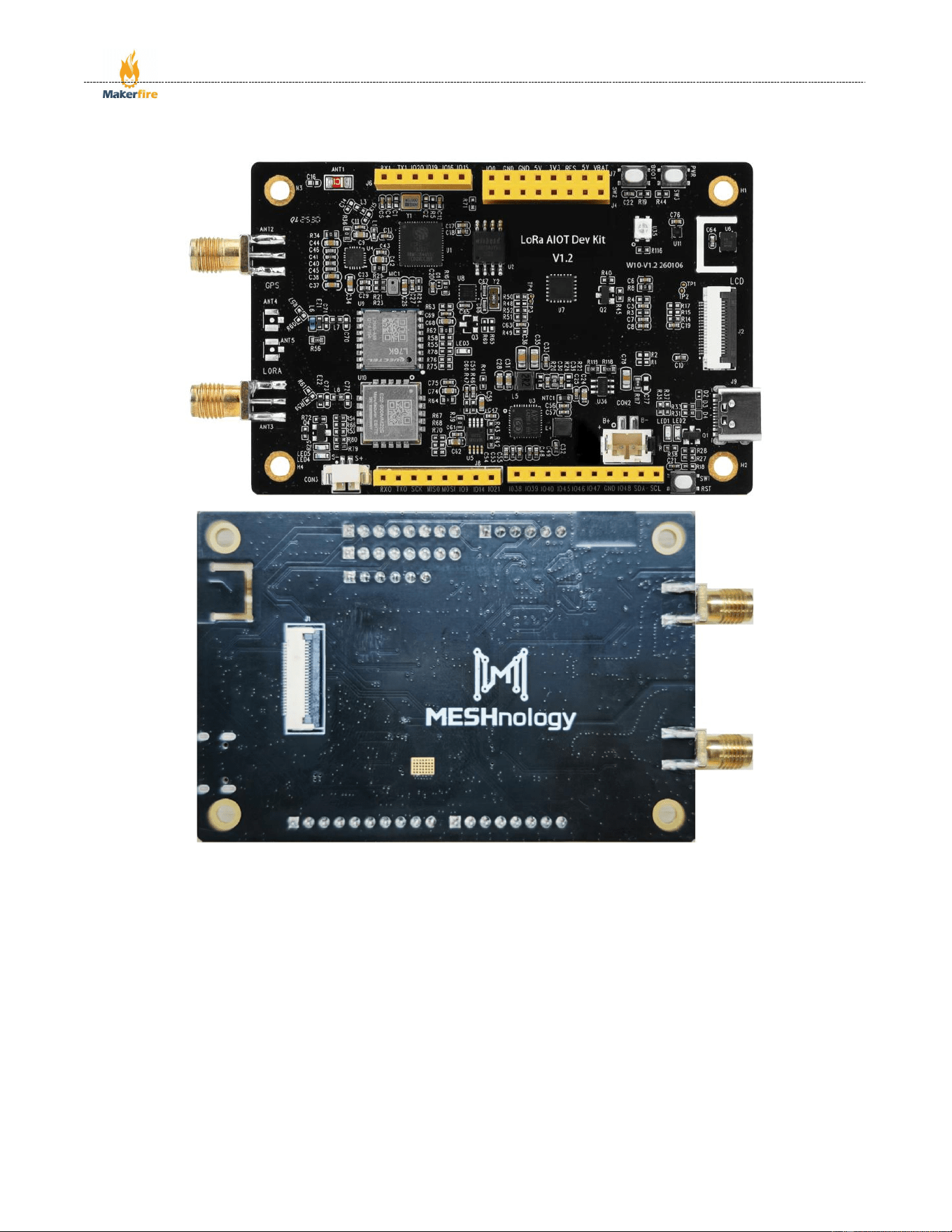
This product is primarily designed to provide an IoT development kit for IoT engineers, smart
hardware engineers, open-source hardware enthusiasts, tech-savvy individuals in North America, and
university IoT programming courses. It offers a hardware development platform supporting Wi-Fi,
Bluetooth and LoRa communication technologies. Furthermore, as the product is designed to the
Arduino UNO standard interface, it is compatible with Arduino peripheral modules and expansion
boards, offering developers greater flexibility;
Target audience: IoT engineers, smart hardware engineers, open-source hardware enthusiasts, tech-
savvy men in North America, and university students with an interest in programming.
Shenzhen Makerfire Technology Co., Ltd.
5 / 24
1.5 Product illustration
Shenzhen Makerfire Technology Co., Ltd.
6 / 24
1.6 Dimension diagram
1.7 Hardware specifications
Function category
Function description
Product name
LoRa AIOT Dev Kit
Power supply interface
USB TYPE-C 5V/3A
main control chip
ESP32-S3R8 Xtensa® 32-bit LX7 dual-core microprocessor, clocked at up
to 240 MHz
LoRa module
The EBYTE E22-900MM22S supports the 850–930 MHz frequency band
and the LoRaWAN protocol
GPS module
The Quectel L76K supports multiple satellite systems, including GPS,
GLONASS, BDS and QZSS
LCD
Supports a 3.5-inch capacitive touchscreen with an FPC (SPI+I2C)
interface, 320×480 resolution and 262K colours
Supports a 3.5-inch TFT display with an Arduino (LCD) interface, resolution
320×480
Supports a 1.54-inch ISP full-view SPI interface display with a resolution of
240×240 and full-colour RGB
Supports a 1.3-inch OLED LCD display with an SPI interface, 128×64
resolution, and full-colour RGB
Supports a 1.47-inch TFT LCD display with an SPI interface, resolution 172
×320, full-colour RGB
Camera
Supports OV2640 2-megapixel cameras
Supports the OV5640 5-megapixel camera
Audio codecs
ES8311 low-power audio codec chip, 24-bit, supporting sampling rates from
8 to 96 kHz

Shenzhen Makerfire Technology Co., Ltd.
7 / 24
Temperature and humidity
sensor
SHT41 Temperature: 0–75 °C, accuracy ±0.2 °C; Humidity: 0–100%,
accuracy ±2%
IMU sensor
QMI8658 6-axis MEMS IMU chip, integrating a 3-axis gyroscope and a 3-
axis accelerometer
RTC (Real-Time Clock)
The PCF85063 RTC calendar chip has extremely low power consumption,
with a standby current of just 0.25 μA
Power management
The AXP2101 is a highly integrated PMIC featuring four built-in DC-DC
converters and one battery monitor
IO expansion port
Compatible with the Arduino interface, featuring 2 UART ports, 1 ADC port,
1 SPI port and 1 I2C port
Debugging interface
1 x JTAG port
USB port
1 USB 2.0 communication port, primarily utilising the USB CDC function
Button
1 reset button, 1 BOOT button
Storage
External 16MB SPI Flash
Number of board layers
4th floor
Board material
RF-4 (fibreglass board)
Weight per board
30.8g
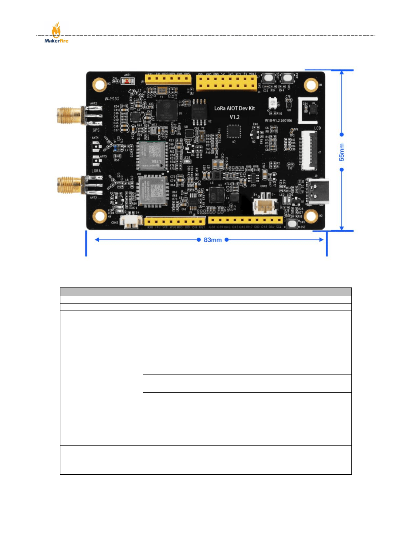
Spacing between mounting
holes
73.80*45.00mm
Board dimensions
83.40*55.00mm
Operating temperature
-40℃~85℃
FCC ID
2BRTY-DEVK
Product Certification
FCC、CE、RoHs

Shenzhen Makerfire Technology Co., Ltd.
8 / 24
Product Features
2.1 Overview of Features
This product utilises a processor based on the Xtensa® 32-bit LX7 dual-core architecture, with a clock
speed of up to 240 MHz and significantly higher floating-point performance than processors based on the
ARM Cortex-M33 architecture; it features mainstream LoRa SX1262 and GPS L76K modules on board,
making it highly convenient for use and expansion in wireless communication and outdoor positioning
applications; Furthermore, the board is equipped with an audio codec chip and power amplifier components;
when used in conjunction with a display, it enables the straightforward implementation of XiaoZhi AI voice
dialogue and chat functions. The board also features temperature and humidity sensors, as well as inertial
sensors, allowing for flexible use in environmental monitoring and motion control applications. Additionally,
the board incorporates an RTC (Real-Time Clock) chip, enabling the transmission of timestamped data
during communication to ensure the timeliness and accuracy of the data;
2.2 Product Features
1. Features an Xtensa® 32-bit LX7 dual-core processor with a clock speed of up to 240 MHz, and built-in
Wi-Fi and BLE functionality;
2. Integrated with LoRa and GPS modules, it effortlessly meets communication and data logging
requirements in areas without network coverage, as well as outdoor positioning and tracking needs;
3. Equipped with an on-board IMU and temperature and humidity sensors, it enables motion detection
and environmental monitoring functions, and, when paired with wireless connectivity, facilitates
synchronisation and data upload;
4. The on-board RTC clock chip enables clock, alarm and perpetual calendar functions, and can also
serve as a timestamp reference for wireless communications;
5. Equipped with an audio codec chip and compatible with mainstream LCD and OLED displays, it
enables easy implementation of AI-powered voice intercom and chat functions;
6. Equipped with a camera interface, it supports OV2640 and OV5640 cameras, enabling the capture,
display and upload of images and video;
7. Equipped with a lithium battery port, this product can be powered and operated normally even when
not connected to a USB source;
8. Expansion I/O compatible with the Arduino interface, capable of supporting various modules and
accessories for Arduino;
Shenzhen Makerfire Technology Co., Ltd.
9 / 24
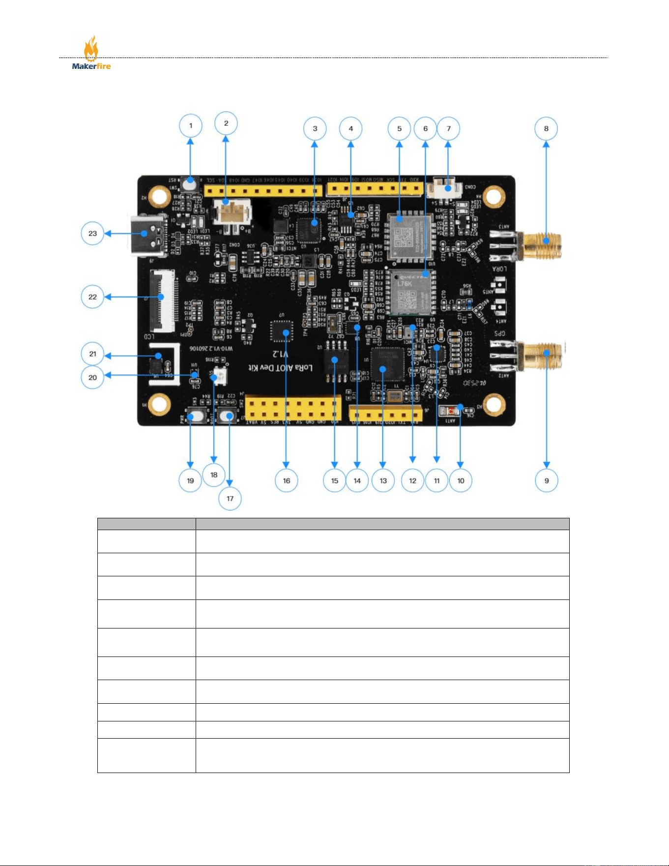
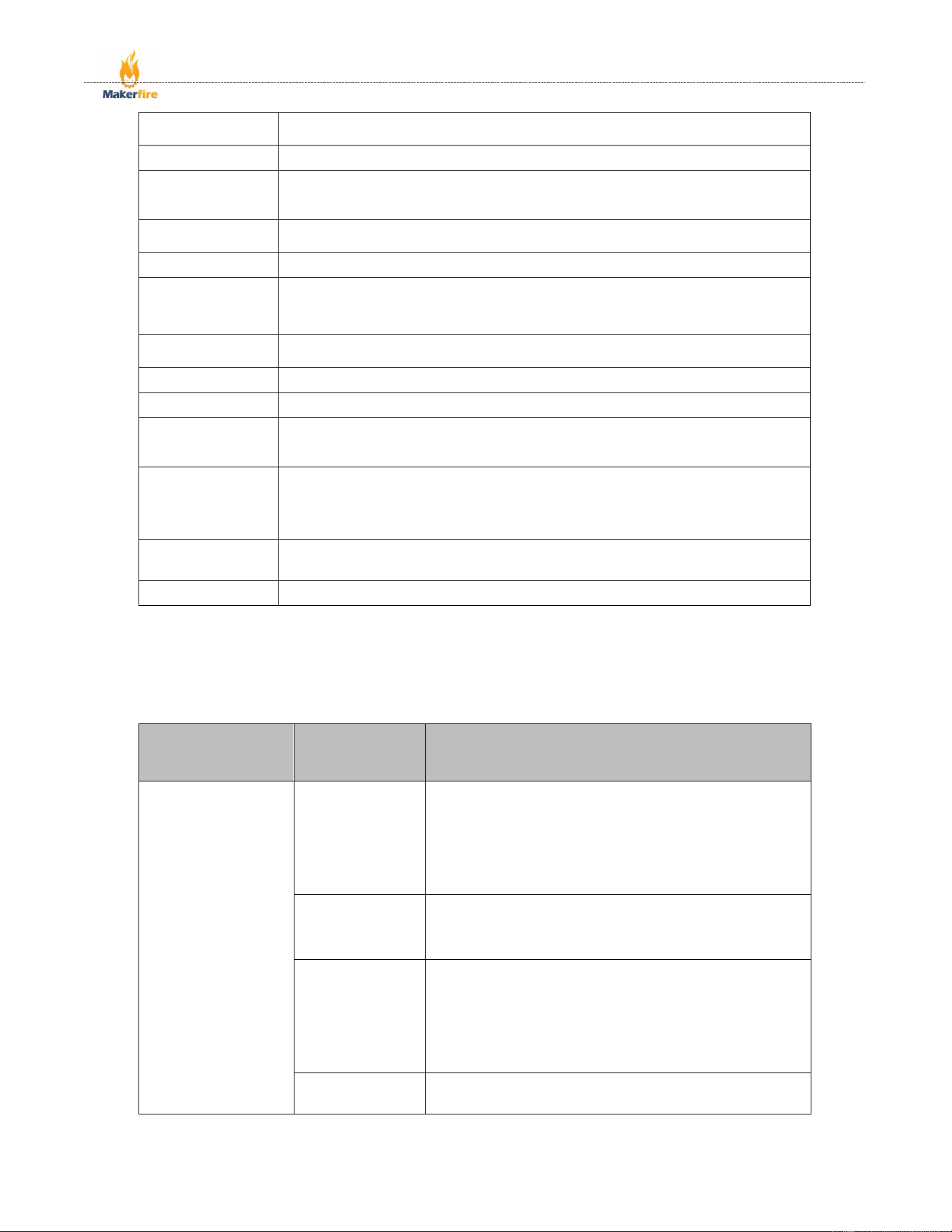
2.3 Introduction to Resources
Reference number
Resource description
1
RESET button: Press to restart the device; used for fault recovery and to restart the
programme
2
PH2.0 lithium battery interface, connected to a 3.7V lithium battery via a PH2.0_2PIN
connector
3
The AXP2101 power management IC handles power distribution, voltage regulation
and power consumption control, ensuring a stable power supply to the device
4
The NS4150B audio amplifier delivers an output power of up to 2.8W under a 4Ω
load, with a maximum output of 3W.
5
Ebit E22 - 900MM22S LoRa module, based on the SX1262 chip, operating in the
850–930 MHz band, with a maximum transmission power of 22 dBm.
6
The Quectel L76K GPS module supports multiple satellite systems, including GPS,
GLONASS, BDS and QZSS.
7
PH1.25 speaker connector: a connector for audio output, supporting speakers with
a maximum power rating of 3W.
8
SMA connector, for connecting a LoRa 850–930 MHz antenna.
9
SMA connector, for connecting an active GPS antenna.
10
A surface-mounted ceramic antenna that enables the transmission and reception of
wireless signals (Wi-Fi, Bluetooth) and operates without the need for an external
antenna.
Shenzhen Makerfire Technology Co., Ltd.
10 / 24
11
The ES8311 is a low-power audio codec chip that processes audio signals (encoding
and decoding), enabling devices to record and play back audio.
12
Microphone, used to capture audio signals for recording and voice interaction.
13
The ESP32, powered by the S3R8 core, is a system-on-chip (SoC) that integrates
Wi-Fi and Bluetooth functionality. It operates at a frequency of 240 MHz and features
8 MB of pseudo-static random-access memory (PSRAM) for expanded storage.
14
The PCF85063 RTC clock chip provides an accurate time reference, enabling
devices to function as real-time clocks.
15
W25Q128JVSIQ 16MB NOR flash memory chip.
16
The MCP23017 is a 16-bit I²C serial bus I/O expansion chip that supports a wide
voltage range of 1.8V to 5.5V and features interrupt outputs, weak pull-up and
configuration registers.
17
The BOOT button, which is used to select the boot mode, is often used in conjunction
with the reset button to flash firmware onto the device.
18
3030 0.6W multicoloured LED
19
PWR power button, used to switch the device on and off.
20
The QMI8658 six-axis inertial measurement unit (IMU) comprises a three-axis
gyroscope (for measuring angular velocity) and a three-axis accelerometer (for
measuring acceleration).
21
The SHT41 temperature and humidity sensor features an I²C interface and offers
high accuracy (±0.1°C/±1.5% RH), low power consumption and a compact size (2.5
×2.5×0.9 mm).
22
3.5-inch LCD display FPC connector, featuring integrated SPI, I ²C and SDIO
interfaces
23
Type-C port, used for powering the device and data transfer.
2.4 Features
2.4.1 SOC Features
Component name
Classification
by
characteristics
Product Features
ESP32 - S3
Processor
performance
It features an Xtensa® 32-bit LX7 dual-core processor with
a clock speed of up to 240 MHz. Single-core performance
reaches 613.86 CoreMark, whilst dual-core performance
reaches 1181.60 CoreMark. It supports SIMD instructions
and a single-precision floating-point unit (FPU), as well as
AI instruction acceleration, enabling it to handle complex
computational and real-time control tasks with ease.
Storage resources
Featuring 384KB of ROM, 512KB of SRAM and 16KB of
RTC SRAM, with 8MB of built-in PSRAM and support for
external Flash memory, it meets the requirements for
multitasking and large-scale data caching.
Wireless
communication
Supports dual-mode wireless communication via 2.4GHz
Wi-Fi and Bluetooth® Low Energy (Bluetooth® LE). Wi-Fi
supports the IEEE 802.11 b/g/n protocols, with 20 MHz and
40 MHz channel bandwidths on the 2.4 GHz band, and
data rates of up to 150 Mbps; Bluetooth supports Bluetooth
5 and Bluetooth mesh, with data rates of 125 Kbps, 500
Kbps, 1 Mbps and 2 Mbps.
Peripheral ports
Features 45 GPIO pins and supports a variety of digital
interfaces, including 4×SPI, 1×LCD interface, 1×DVP

Shenzhen Makerfire Technology Co., Ltd.
11 / 24
camera interface, an LED PWM controller, 1× full-speed
USB OTG, 1× USB Serial/JTAG controller, 1× SDIO host
interface, a general-purpose DMA controller, 1× TWAI®
controller, 2× 12-bit SAR ADCs, and 1× temperature
sensor, amongst others.
Safety features
It supports secure boot and flash encryption, and features
a built-in hardware encryption accelerator, including a
random number generator (RNG) and digital signature
capabilities. It also incorporates a ‘World Controller’
peripheral, providing two fully isolated execution
environments to ensure data security.
Low-power
management
It features a power management unit with five power
consumption modes and an integrated ultra-low-power
coprocessor (ULP), comprising an ULP-RISC-V
coprocessor and an ULP-FSM coprocessor. With a current
draw as low as 10μA in deep sleep mode, it is ideal for
battery-powered devices.
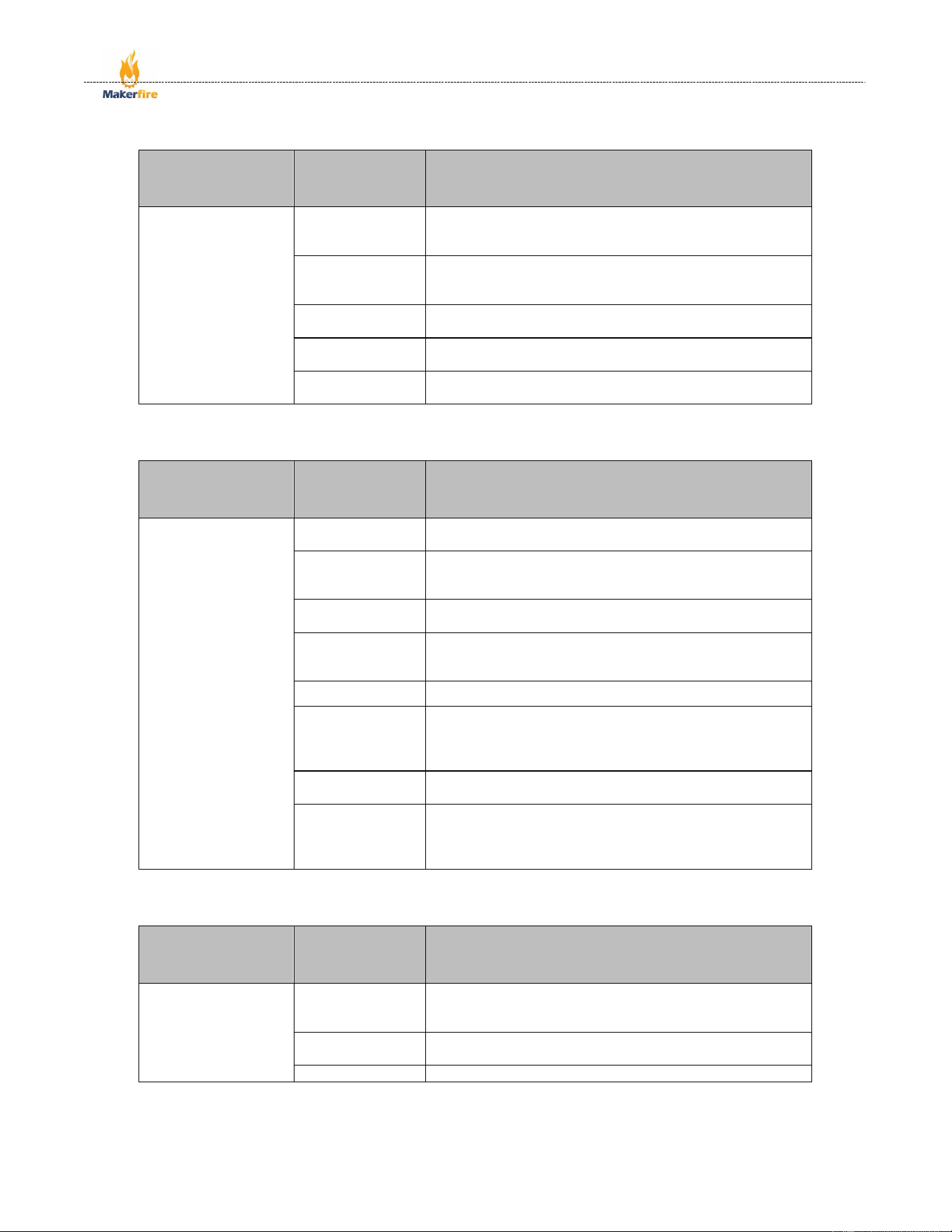
2.4.2 LoRa Features
Component name
Classification
by
characteristics
Product Features
SX1262
Communication
performance
- Transmission power: up to +22 dBm (high-efficiency
integrated power amplifier)
- Receiver sensitivity: as low as –148 dBm
- Maximum link budget: 170 dB
- Interference immunity: 88 dB of interference immunity at 1
MHz offset; 19 dB of co-channel rejection in LoRa mode
- Modulation schemes: Supports FSK, GFSK, MSK, GMSK,
LoRa and long-range FHSS
- Data rates: Programmable up to 62.5 kbps in LoRa mode
and up to 300 kbps in FSK mode
Low-power
characteristics
- The active receiver draws just 4.6 mA of current, making it
suitable for battery-powered applications
Highly integrated
- Integrates a DC-DC converter and an LDO, reducing the
number of external components and lowering system costs
and PCB footprint
Packed with
features
- Built-in bit synchroniser (for clock recovery)
- Features automatic channel activity detection (CAD) and
ultra-fast AFC
Wide frequency
coverage
- Covers a continuous frequency range from 150 MHz to
960 MHz, supporting the major global Sub-GHz ISM bands
in compliance with
regulatory
requirements
- Complies with the physical layer requirements of the
LoRaWAN specification;
- Complies with radio regulations such as ETSI EN 300
220, FCC CFR 47 Part 15, and ARIB T-108 in China and
Japan
Shenzhen Makerfire Technology Co., Ltd.
12 / 24
2.4.3 GPS Features
Component name
Classification
by
characteristics
Product Features
L76K
Satellite system
support
Supports GPS, BDS, GLONASS and QZSS multi-satellite
systems, enabling both multi-system combined positioning
and single-system independent positioning
Assisted
positioning
function
Supports AGNSS functionality
Built-in
components
Built-in low-noise amplifier (LNA) and surface acoustic
wave filter
Key features
Provides users with a fast, accurate and high-performance
positioning experience
Layout method
Configuration is carried out via NMEA commands or a
binary protocol; the default baud rate is 9600 bps.
2.4.4 IMU Features
Component name
Classification
by
characteristics
Product Features
QMI8658
Sensor type
6-axis inertial measurement unit, integrating a 3-axis
gyroscope and a 3-axis accelerometer
Gyroscope noise
The QMI8658C has a figure of merit of 15 mdps/√Hz,
whilst the QMI8658A has a figure of merit of 13 mdps/√Hz
Accelerometer
noise
QMI8658C is 200 µg/√Hz, and QMI8658A is 150 µg/√Hz
Dynamic range
The gyroscope ranges from ±16°/s to ±2048°/s, and the
accelerometer ranges from ±2g to ±16g
Interface type
Supports MIPI™ I3C, I2C and 3-wire or 4-wire SPI
Directional
accuracy
When used in conjunction with the XKF3 9D sensor fusion,
pitch and roll accuracy is ±3°, and yaw / heading accuracy
is ±5°
FIFO
1536-byte FIFO, which can be used to buffer sensor data in
order to reduce system power consumption
Programmable
features
The accelerometer and gyroscope sensors feature signal
processing paths, digitally programmable data rates and
filtering; they support digitally programmable sampling
rates and filters
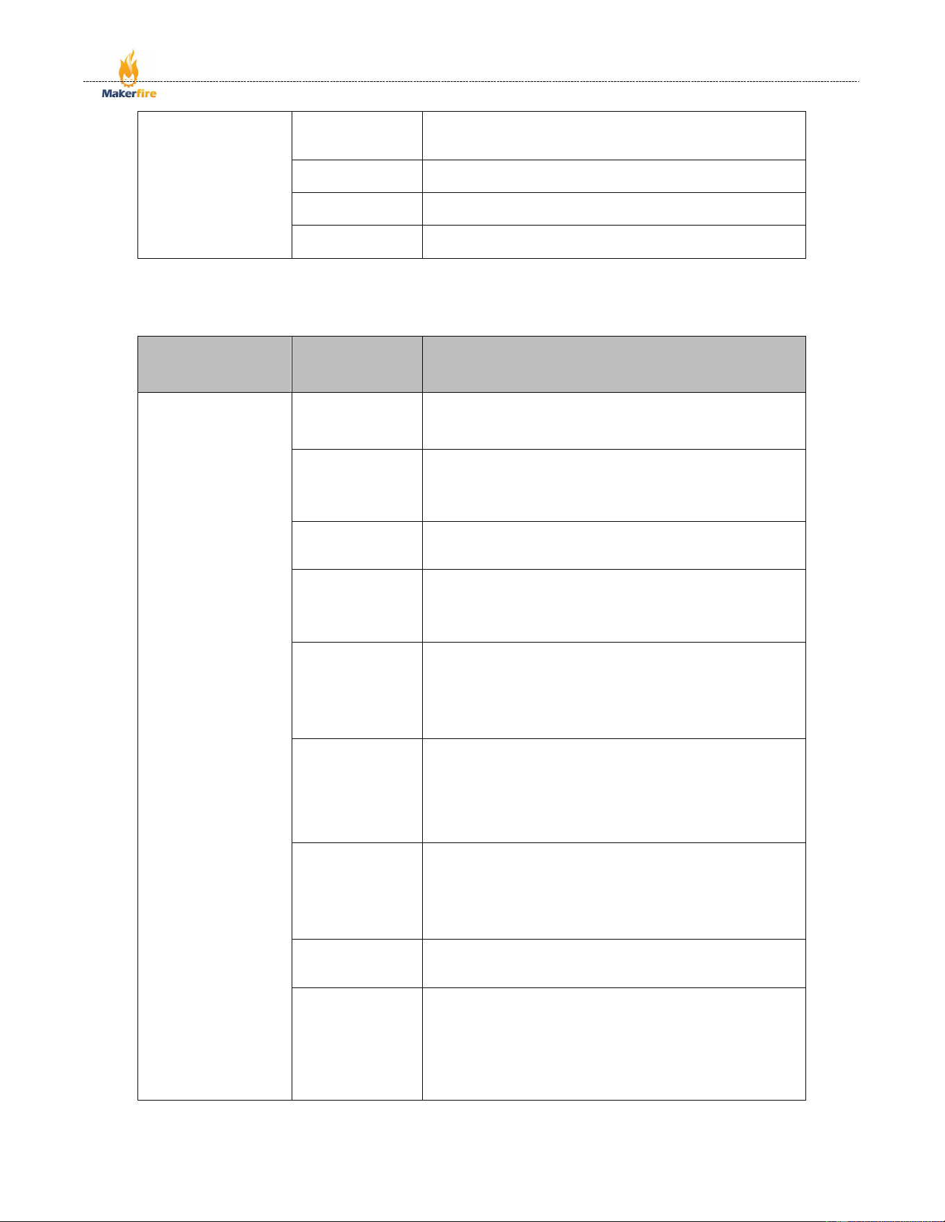
2.4.5 RTC Features
Component name
Classification
by
characteristics
Product Features
PCF85063
Timer function
Based on a 32.768 kHz quartz crystal, it displays the year,
month, day, day of the week, hour, minute and second; the
time format supports both 12-hour and 24-hour notation
Communication
interfaces
I²C bus interface, with a maximum data rate of 400 kbit/s
Operating voltage
0.9V - 5.5V
Shenzhen Makerfire Technology Co., Ltd.
13 / 24
Clock output
Programmable clock output, with selectable frequencies of
32.768 kHz, 16.384 kHz, 8.192 kHz, 4.096 kHz, 2.048 kHz,
1.024 kHz and 1 Hz
Frequency
adjustment
Features a programmable offset register for fine-tuning the
clock
Interrupt
functionality
Supports one-minute and half-minute interruptions
Other features
Oscillator stop detection function, Power-On Reset (POR),
alarm function, countdown timer
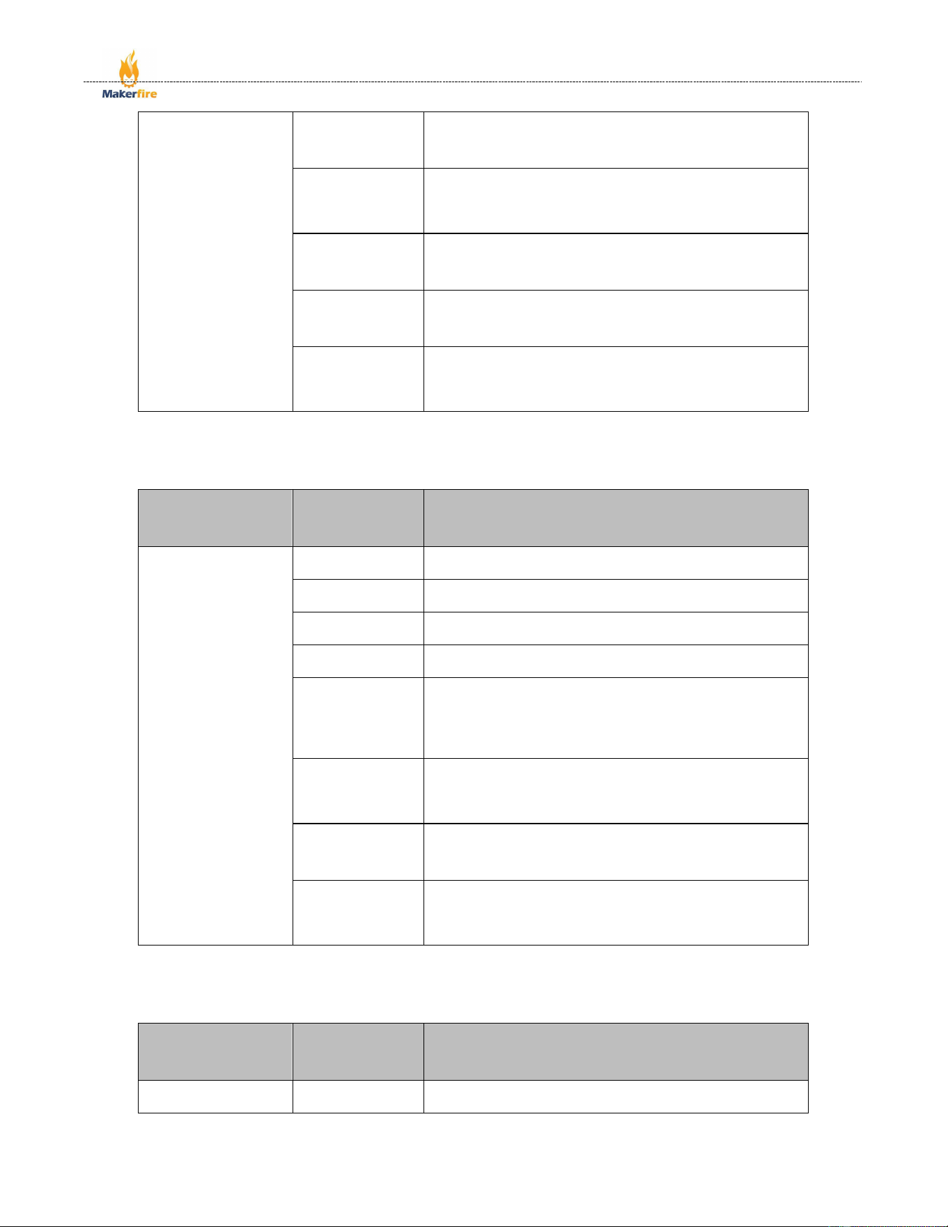
2.4.6 IO Features
Component name
Classification
by
characteristics
Product Features
MCP23017
I/O Expansion
Includes 16 configurable I/O pins, divided into two groups:
PORTA (GPA0–GPA7) and PORTB (GPB0–GPB7), which
are set to input mode by default;
Operating Voltage
Wide input voltage range: 1.8 V to 5.5 V (-40 °C to +85 °
C); 2.7 V to 5.5 V (-40 °C to +85 °C); 4.5 V to 5.5 V (-40 °
C to +125 °C)
Standby Current
Low-power design: maximum 1 µA at -40°C to +85°C;
maximum 3 µA at 4.5 V to 5.5 V and +85°C to +125°C
Communication
Interfaces
Supports high-speed I²C communication with selectable
baud rates of 100 kHz, 400 kHz and 1.7 MHz; supports
Byte mode and Sequential mode, with the address pointer
capable of being automatically incremented or fixed
Interrupt Outputs
Equipped with dual interrupt pins (INTA and INTB), which
can be configured to operate independently or in
conjunction with a logical OR function; supports three
output modes: active-high, active-low and open-drain;
interrupt sources can be set to pin level changes or
mismatches with the default value in the DEFVAL register
I/O Port
Characteristics
Supports input polarity reversal (configured via the
IPOLA/IPOLB registers); an internal 100 kΩ weak pull-up
resistor can be enabled (typical pull-up current of 75 µA at
VDD = 5 V); pins support bidirectional data transmission
and are in a high-impedance state when configured as
inputs
Output Drivers
The maximum sink current for a single output pin is 25 mA,
and the maximum source current is 25 mA; the low output
voltage is ≤0.6 V (IOL = 8.0 mA, VDD = 4.5 V), and the
high output voltage is ≥VDD – 0.7 V (IOH = –3.0 mA,
VDD = 4.5 V)
ESD Protection
All pins are ESD-protected, with a human body model
(HBM) rating of 4 kV and a machine model (MM) rating of
400 V.
Register
Configuration
Includes 22 independent registers (11 pairs of register
sets); core configuration registers include: IODIRA/B (I/O
direction), GPINTENA/B (interrupt enable), DEFVALA/B
(interrupt default values), INTCONA/B (interrupt control),
IOCON (device configuration), etc.; Supports BANK bit
switching for register mapping mode (0 for continuous
addressing, 1 for port-based addressing)
Shenzhen Makerfire Technology Co., Ltd.
14 / 24
Hardware address
Equipped with three hardware address pins (A0, A1 and
A2), it supports the daisy-chaining of up to eight devices on
a single I²C bus, enabling multi-device expansion
Reset function
An external RESET pin is provided; the reset pulse must be
at least 1 µs in duration. Upon reset, all registers revert to
their default values and the I/O pins are set to input mode
by default.
Bus load
I²C bus capacitive load: maximum 400 pF in 100 kHz/400
kHz mode, maximum 100 pF in 1.7 MHz mode; the SDA
pin supports slew rate control
Packaging
specifications
28-pin multi-package options: PDIP (300 mil), SOIC (300
mil), SSOP, QFN (6×6 mm), suitable for various installation
scenarios
Environmental
characteristics
Operating temperature range: -40°C to +125°C; storage
temperature range: -65°C to +150°C; maximum total power
consumption: 700 mW; suitable for industrial environments
2.4.7 PMIC Features
Component name
Classification
by
characteristics
Product Features
AXP2101
Input voltage
range
Supports a wide input voltage range from 4.5V to 20V;
Output channels
Includes multiple DC-DC converters and LDO regulators,
providing a wide range of power supply output options:
Output current
capacity
- Multiple synchronous buck DC-DC converters (e.g.
DCDC1, DCDC2, etc.), with adjustable output voltage
Charge
management
- Multi-channel LDOs, with fixed or adjustable output
voltages
Power control
Output capabilities vary by channel; for example, the main
DC-DC converters can provide higher currents (e.g. 3A/4A)
to meet the power requirements of the core processor,
whilst LDOs typically provide currents in the range of
several hundred mA
Protection
functions
Built-in lithium battery charge management module,
supporting multiple charge current settings and featuring
charge protection functions (over-voltage, over-current,
over-temperature, etc.)
Low-power
features
Supports multiple power control methods, including enable
pin control and I²C interface configuration, enabling power
sequencing management and dynamic voltage regulation;
Interfaces and
communication
Integrated overvoltage protection (OVP), undervoltage
protection (UVP), overcurrent protection (OCP) and
overtemperature protection (OTP), ensuring stable and
safe system operation;
2.4.8 Audio Features
Component name
Classification
by
characteristics
Product Features
ES8311
Audio input
Supports microphone input (MIC IN) and line input (LINE
IN), with configurable gain;
Shenzhen Makerfire Technology Co., Ltd.
15 / 24
Audio output
Supports headphone output (HP OUT) and line output
(LINE OUT), with volume control;
Sampling rate
Supports a range of sampling rates, typically covering 8
kHz to 48 kHz, to meet the requirements of various audio
applications;
Resolution
Supports digital audio resolutions such as 16-bit and 24-bit,
providing high audio precision;
Signal-to-noise
ratio (SNR)
Both microphone input and output channels feature a high
signal-to-noise ratio, typically exceeding 90dB, ensuring
audio quality;
Power
consumption
Low-power design with multiple operating modes (such as
normal mode and sleep mode), suitable for battery-
powered devices;
Interfaces
Supports the I²S digital audio interface for transmitting
audio data to the host controller; supports the I²C control
interface for configuring chip parameters;
Audio features
Some models may incorporate basic audio processing
functions, such as volume control and mute control
2.4.9 Sensor Features
Component name
Classification
by
characteristics
Product Features
SHT41
Measurement
range
Temperature: -40°C to 125°C; Humidity: 0% RH to 100%
RH
Measurement
accuracy
Temperature: ±0.2°C; Humidity: ±1.8% RH
Supply voltage
range
1.08 V to 3.6 V
Average supply
current
0.4 μA (at a measurement rate of 1 Hz)
Standby current
80 nA
Communication
interface
I²C
Response time
Humidity: 4 s (at 63% RH); Temperature: 2 s (at 63% RH)
Shenzhen Makerfire Technology Co., Ltd.
16 / 24
2.5 Hardware Interfaces
2.5.1 IO Extension interface
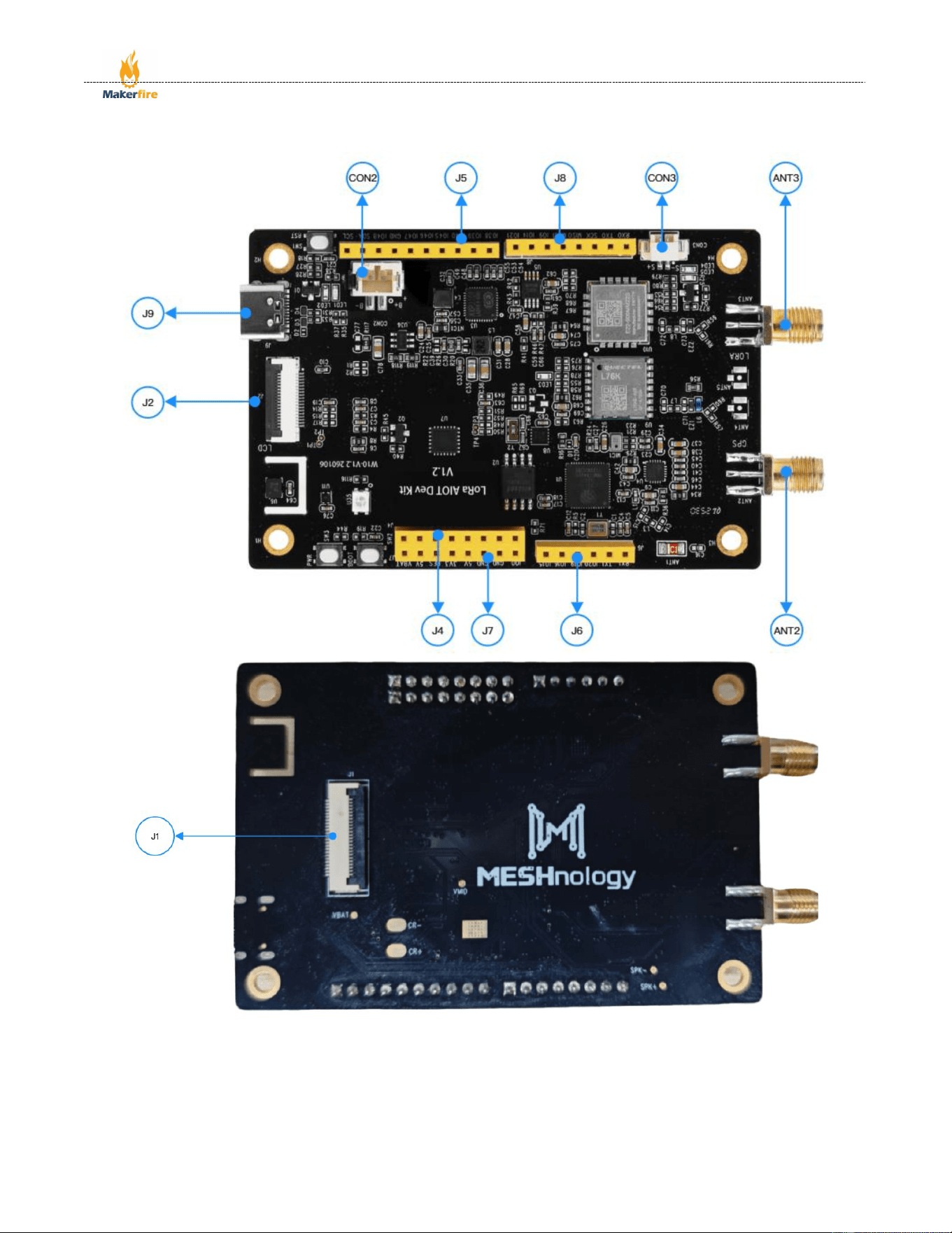
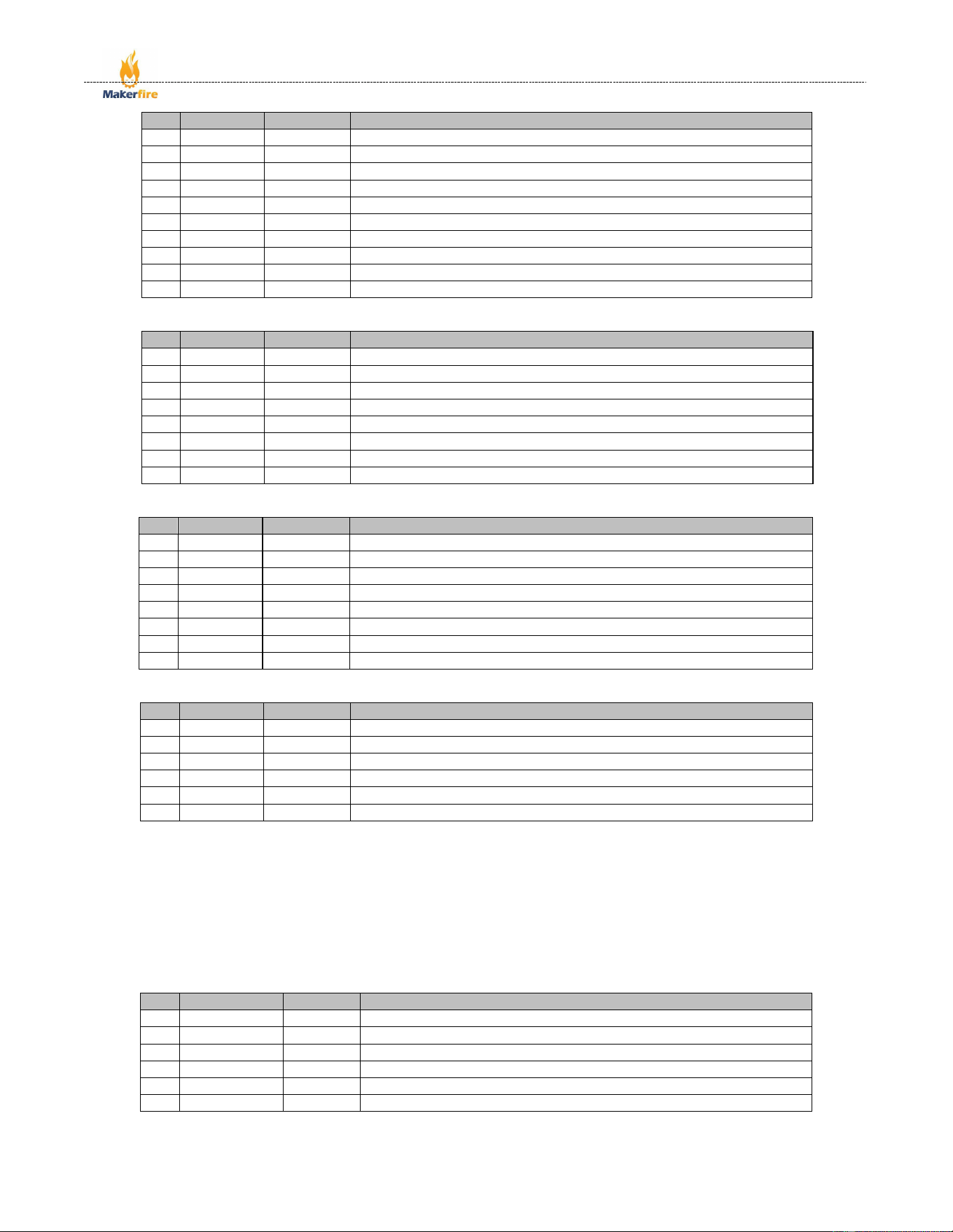
J5:Interface definitions from left to right
Shenzhen Makerfire Technology Co., Ltd.
17 / 24
No.
Name
Type
Function
1
SCL
I/O
GPIO41, CLK_OUT1, MTDI
2
SDA
I/O
GPIO42, MTMS
3
GPIO48
I/O
GPIO48, SPICLK_N
4
GND
G
Ground
5
GPIO47
I/O
GPIO47, SPICLK_P
6
GPIO46
I/O
GPIO46
7
GPIO45
I/O
GPIO45
8
GPIO40
I/O
GPIO40, CLK_OUT2, MTDO
9
GPIO39
I/O
GPIO39, CLK_OUT3, SUBSPICS1, MTCK
10
GPIO38
I/O
GPIO38, FSPIWP, SUBSPIWP
J8:Interface definitions from left to right
No.
Name
Type
Function
1
GPIO21
I/O
GPIO21
2
GPIO14
I/O
GPIO14, TOUCH14, ADC2_CH3, FSPIDQS, SUBSPIWP, FSPIWP
3
GPIO9
I/O
GPIO9, TOUCH9, ADC1_CH8, SUBSPIHD, FSPIHD
4
MOSI
I/O
GPIO13, TOUCH13, ADC2_CH2, FSPIIO7, SUBSPIQ, FSPIQ
5
MISO
I/O
GPIO11, TOUCH11, ADC2_CH0, FSPIIO5, SUBSPID, FSPID
6
SCK
I/O
GPIO12, TOUCH12, ADC2_CH1, FSPIIO6, SUBSPICLK, FSPICLK
7
TX0
I/O
GPIO43, U0TXD, CLK_OUT1
8
RX0
I/O
GPIO44, U0RXD, CLK_OUT2
J7:Interface definitions from left to right
No.
Name
Type
Function
1
VBAT
P
Input 3.7~4.2V, Battery positive terminal input
2
5V
P
Output 5.0V, power supply for external sensor
3
RES
I
CHIP_PU, Connect to RST switch
4
3V3
P
Output 3.3V, power supply for external sensor
5
5V
P
Output 5.0V, power supply for external sensor
6
GND
G
Ground
7
GND
G
Ground
8
IO0
I/O
GPIO0
J6:Interface definitions from left to right
No.
Name
Type
Function
1
IO15
I/O
GPIO15, U0RTS, ADC2_CH4, XTAL_32K_P
2
IO16
I/O
GPIO16, U0CTS, ADC2_CH5, XTAL_32K_N
3
IO19
I/O
GPIO19, U1RTS, ADC2_CH8, CLK_OUT2, USB_D
4
IO20
I/O
GPIO20, U1CTS, ADC2_CH9, CLK_OUT1, USB_D+
5
TX1
I/O
GPIO17, U1TXD, ADC2_CH6
6
RX1
I/O
GPIO18, U1RXD, ADC2_CH7, CLK_OUT3
2.5.2 USB Interface
J9:USB Type-C port, supporting a maximum power output of 5V/3A, compatible with PD fast chargers.
2.5.3 CAM FPC Interface
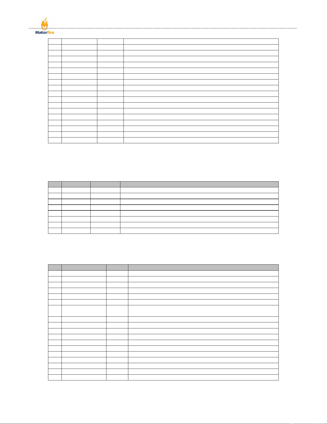
J1:Top-down interface definition
No.
Name
Type
Function
1
NC
NC
Reserved
2
AGND
P
Analog Ground
3
TWI_SDA
I/O
SCCB communication data signal.
4
AVDD2.8V
P
power supply for a 2.8V analog circui
5
TWI_CLK
I
SCCB communication clock signal.
6
RESET
I
Reset signal (active low)
Shenzhen Makerfire Technology Co., Ltd.
18 / 24
7
CAM_VSYNC
O
Frame synchronization signal output.
8
CAM_PWDN
I
Power-down enable (active high).
9
CAM_HREF
O
Line synchronization signal output.
10
DVDD1.5V
P
Power supply for a 1.5V digital circuit.
11
DOVDD2.8V
P
power supply for a 2.8V digital circui.
12
CAM_D7
O
8-bit data output.
13
CAM_XCLK
I
Basic working clock input pin of OV5640.
14
CAM_D6
O
8-bit data output.
15
GND
G
Module ground wire
16
CAM_D5
O
8-bit data output.
17
CAM_PCLK
O
Pixel clock output.
18
CAM_D4
O
8-bit data output.
19
CAM_D0
O
8-bit data output.
20
CAM_D3
O
8-bit data output.
21
CAM_D1
O
8-bit data output.
22
CAM_D2
O
8-bit data output.
23
VCC3V3
P
Module power supply pin, connected to 3.3V power supply.
24
GND
G
Module ground wire.
2.5.4 LCD Extension interface
J4:Interface definitions from left to right
No.
Name
Type
Function
1
GND
G
Ground
2
VCC
P
3.3V power input
3
CLK
I/O
SPI bus clock pin
4
MOSI
I/O
SPI bus data pin
5
RES
I/O
OLED reset pin
6
DC
I/O
Data or command switch pin
7
CS
I/O
SPI bus choose pin
8
BL
I/O
Backlight control pin
2.5.5 LCD FPC Interface
J2:Top-down interface definition
No.
Name
Type
Function
1
3.3V
P
3.3V power input for LCD display.
2
LCD_BL
I
LCD backlight control from PWM.
3
GND
G
Ground
4
SCLK
I
SPI communication SCLK pin
5
MOSI/SD_CMD
I
SPI communication MOSI pin /SDIO communication CMD pin
6
MISO/SD_DAT0
O
SPI communication MISO pin / SDIO communication DAT0 pin
7
LCD_DC
I
Data/command pin for LCD, low level indicates command, high
level indicates data.
8
LCD_TP_RST
I
Reset pin for LCD and TP, active at low level.
9
LCD_CS
I
Chip select pin for LCD, active at low level.
10
SD_CS/SD_DAT3
I/O
Chip select pin for Micro SD / SDIO communication DAT3 pin
11
SD_DAT2
I/O
SDIO communication DAT2 pin
12
LCD_TP_RST
I
Reset pin for LCD and TP, active at low level
13
TP_SCL
I
I2C communication Clock pin for TP
14
TP_SDA
I/O
I2C communication Data pin for TP
15
TP_INT
O
Touch Interrupt pin for TP
16
SD_DAT1
I/O
SDIO communication DAT1 pin
17
NC
/
Reserved
18
NC
/
Reserved
Shenzhen Makerfire Technology Co., Ltd.
19 / 24
2.5.6 SMA Interface
ANT3: Connect an SMA male-to-female LoRa 850–930 MHz whip antenna or external antenna
ANT2: Connect an SMA male-to-female GPS active antenna
2.5.7 Lithium-ion battery interface
CON2:Top-down interface definition
No.
Name
Type
Function
1
GND
G
Ground
2
VBAT+
P
Input 3.7~4.2V, Battery positive terminal input
2.5.8 Speaker connections
CON3:Interface definitions from left to right
No.
Name
Type
Function
1
SPK+
A
Audio output positive pole
2
SPK-
A
Audio output Negative pole
2.6 Performance Indicators
Device type
Component
name
Performance indicators
Main SoC
ESP32-S3
Processor: Xtensa® 32-bit LX7 microprocessor, with a maximum
operating frequency of 240 MHz.
Memory: 512KB of on-board SRAM, with support for external SPI
flash and PSRAM.
Communication interfaces: Supports Wi-Fi 4 (802.11b/g/n), Bluetooth
5 (BLE) and Bluetooth Mesh, with multiple UART, SPI, I2C and other
interfaces.
Security features: Built-in hardware security module, supporting
security functions such as encryption and authentication.
LoRa modules
SX1262
Supported frequency bands: Supports the 137–1020 MHz band.
Transmit power: Maximum output power up to 22 dBm.
Receiver sensitivity: Up to -148 dBm.
Modulation schemes: Supports LoRa, FSK, GFSK and other
modulation schemes.
Communication interface: SPI interface.
Operating bands: EU868 / US915 / AU915 / AS923 / KR920 / IN865.
GPS modules
L76K
Reception bands: GPS – L1 C/A, GLONASS – L1, BDS – B1I,
QZSS – L1 C/A
Supported satellite systems: GPS, GLONASS, BDS and QZSS
Sensitivity: Acquisition: -147 dBm, Tracking: -161 dBm, Reacquisition:
-162 dBm
Horizontal positioning accuracy: 2.0 m
Speed accuracy: 0.1 m/s (without assistance)
Acceleration accuracy: 0.1 m/s² (without assistance)
Time to First Fix (TTFF): With AGNSS enabled, 5.5 s for cold start and
2 s for warm start; with AGNSS disabled, 30 s for cold start and 2 s for
warm start
IMU modules
QMI8658
Sensor type: 6-axis inertial measurement unit (3-axis gyroscope + 3-
axis accelerometer).

Shenzhen Makerfire Technology Co., Ltd.
20 / 24
Gyroscope performance: Noise density as low as 15 mdps/√Hz, with a
dynamic range of ±16°/s to ±2048°/s.
Accelerometer performance: Noise density of 200 µg/ √Hz, with a
dynamic range of ±2g to ±16g.
RTC modules
PCF85063
Accuracy: Typical accuracy at 25°C is ±20 to ±50 ppm.
Low power consumption: Low supply current of 0.22 μA.
Communication protocol: I²C protocol, with a maximum data rate of 400
kbit/s.
Features: Includes a programmable alarm, countdown timer and
interrupt output.
I/O expansion
modules
MCP23017
I/O Ports: 16-bit general-purpose bidirectional I/O expansion, divided
into two groups (PORTA and PORTB), configured as inputs by default,
with support for internal weak pull-up.
Communication Protocol: I²C protocol, with data rates of 100 kHz, 400
kHz and 1.7 MHz; three hardware address pins support daisy-chaining
of up to eight devices.
Low Power Consumption: Maximum standby current of 1 μA at room
temperature, 3 μA in high-temperature environments.
Interrupt Function: Dual interrupt pins, supporting multi-mode
configuration and two interrupt trigger sources.
Operating Voltage: Wide voltage range of 1.8 V to 5.5 V, suitable for a
temperature range of -40 °C to +125 °C.
Core configuration: 22 registers, supporting flexible configuration such
as I/O direction and polarity inversion.
PMIC modules
AXP2101
Input voltage range: 3.9V to 5.5V.
Charging function: 100mA–1A linear charger, CV accuracy ±0.5%.
Output channels: Supports 16-channel power output, comprising 5 DC-
DC channels and 11 LDO channels.
Communication interfaces: Supports TWSI and RSB interfaces.
Protection functions: Features overvoltage protection, overcurrent
protection and overtemperature protection.
Audio codecs
ES8311
Audio interfaces: Supports I2S, left-aligned, right-aligned and other
audio interface formats.
Sampling rate: Supports sampling rates from 8 kHz to 96 kHz.
Signal-to-noise ratio: Typical value of 98 dB.
Power consumption: Features a low-power mode, making it suitable for
battery-powered devices.
Temperature
and humidity
sensors
SHT41
Measurement range: Temperature range: -40°C to 125°C; humidity
range: 0% RH to 100% RH.
Accuracy: Temperature accuracy: ±0.2°C (-40°C to 125°C); humidity
accuracy: ±1.8% RH (5% RH to 95% RH).
Communication interface: I²C interface.
Power consumption: Low-power design, suitable for battery-powered
devices.
Power
amplifier
modules
NS4150
Output power: 3W (5V supply, 4Ω load).
Operating voltage range: 3.0V to 5.25V.
Total harmonic distortion: 0.1% (0.5W output power, 3.6V supply).
Efficiency: up to 90%.
Protection features: built-in overcurrent protection, over-temperature
protection and under-voltage protection.
Silicon
microphones
LMA2718T381
Polar pattern: Omnidirectional.
Operating voltage: 1.6 V to 3.6 V.
Operating current: 120 µA.
Shenzhen Makerfire Technology Co., Ltd.
21 / 24
Signal-to-noise ratio: 60 dB.
Storage
modules
W25Q128
Storage capacity: 128 Mbit (16 MB).
Operating voltage: 2.7 V to 3.6 V.
Interfaces: Supports standard SPI, 2-wire SPI, 4-wire SPI and QPI
interfaces; SPI clock frequency up to 104 MHz.
Erase/program cycles: Over 100,000.
Data retention: Over 20 years.
2.7 Specifications
Key specifications
Description
minimum
value
typical
value
maximum value
unit
Supply voltage
USB port supply
voltage
3.9
5.0
5.5
V
Operating current
Total operating current
0.16
228
1024
mA
Operating power
consumption
Total power
consumption
0.62
1140
5632
mW
Lithium battery voltage
Lithium battery supply
voltage
3.0
3.7
4.2
V
RTC battery voltage
RTC battery supply
voltage
2.0
3.0
3.0
V
Speaker power
External speaker
power
0.5
2.8
3.0
W
LoRa
Operating frequency
band
850
-
930
MHz
Transmit power
-9
-
22
dBm
Transmit rate
0.018
-
62.5
Kbps
Transmit current
-
120
-
mA
Receive current
-
10
-
mA
Receive sensitivity
-147
-146
-145
dBm
Blocking power
-
-
10
dBm
Transmission range
-
-
6
km
WiFi
Operating frequency
band
2412
-
2484
MHz
Transmit power
18
-
21
dBm
Transmit rate
1
-
150
Mbps
Transmit current
286
-
340
mA
Operating current
88
-
91
mA
Receiver sensitivity
-98.4
-
-71.4
dBm
BLE
Operating frequency
band
2402
-
2480
MHz
Transmit power
-24
0
20
dBm
Transmit rate
0.125
-
2
mA
Transmit current
-
-
380
mA
Operating current
-
-
95
mA
Receiver sensitivity
-104.5
-
-93.5
dBm
GPS
Receive band
GPS:L1 C/A;GLONASS:L1;BDS:
B1I;QZSS:L1 C/A
MHz
Receive current
-
29
-
mA
Receive sensitivity
-162
-160
-147
dBm
Number of tracking
channels
-
-
32
CH
Update rate
1
1
5
Hz
UART baud rate
9600
9600
115200
bps
Cold start positioning
time
5.5
7.8
30
s
Hot start positioning
time
2
2
-
s

Shenzhen Makerfire Technology Co., Ltd.
22 / 24
Horizontal positioning
accuracy
2.0
-
-
m
Velocity accuracy
0.1
-
-
m/s
Acceleration accuracy
0.1
-
-
m/s²
Timing accuracy
30
-
-
ns
ES8311
Sampling rate
8
-
96
kHz
Signal-to-noise ratio
105
110
115
dB
Operating temperature
Operating temperature
range
-40
25
85
℃

Shenzhen Makerfire Technology Co., Ltd.
23 / 24
About Us
We are a high-tech enterprise specialising in the research, development, production and sale of core
IoT modules. With many years of experience in the ESP series module sector, we are committed to
providing highly reliable, high-performance IoT hardware solutions to customers worldwide.
3.1 Key strengths
Technical Capabilities: We have a dedicated hardware R&D team with in-depth expertise in the
Espressif ESP32-S3 chip technology. We possess end-to-end development capabilities, from module design
to firmware optimisation, and our products undergo rigorous reliability testing and compatibility verification.
Quality Assurance: We adhere to industrial-grade manufacturing standards, utilising high-quality
components and precision manufacturing processes. All modules undergo high and low-temperature testing,
ageing tests and RF performance calibration to ensure stable operation in a wide range of complex
environments.
Support Services: We provide comprehensive technical documentation, development example code
and one-to-one technical consultation services. We support OEM/ODM customisation requirements and
respond swiftly to clients’ product iteration and functional adaptation needs.
3.2 Areas of application
Our products are widely used in smart home, industrial automation, smart agriculture, healthcare,
wearable devices and IoT gateways, providing customers with one-stop ‘hardware + software’ IoT
solutions to support the digital transformation and upgrading of industries.。
3.3 Contact us
Technical support: support@xxx.com (Weekdays 9:00–18:00, rapid response)
Business enquiries: business@xxx.com
Official website: www.xxx.com
3.4 Release Notes
This module forms the core framework of the LoRa AIoT Dev Kit Product Specification V0.1.1; the
content will be continuously optimised in line with product updates and user feedback.

Shenzhen Makerfire Technology Co., Ltd.
24 / 24
FCC warning:
Any Changes or modifications not expressly approved by the party responsible for compliance
could void the user's authority to operate the equipment.
Note: This device complies with Part 15 of the FCC Rules. Operation is subject to the following
two conditions:
(1) This device may not cause harmful interference, and
(2) this device must accept any interference received, including interference that may cause
undesired operation.
These limits are designed to provide reasonable protection against harmful interference in a
residential installation. This equipment generates uses and can radiate radio frequency energy
and, if not installed and used in accordance with the instructions, may cause harmful
interference to radio communications. However, there is no guarantee that interference will not
occur in a particular installation. If this equipment does cause harmful interference to radio or
television reception, which can be determined by turning the equipment off and on, the user is
encouraged to try to correct the interference by one or more of the following measures:
-Reorient or relocate the receiving antenna.
-Increase the separation between the equipment and receiver.
-Connect the equipment into an outlet on a circuit different from that to which the receiver is
connected.
-Consult the dealer or an experienced radio/TV technician for help.
This equipment complies with FCC radiation exposure limits set forth for an uncontrolled
environment. This equipment should be installed and operated with minimum distance 20cm
between the radiator & your body.