
Dear Valued Customer,
Thank you for going with ARCCAPTAIN! We're all about making plasma cutters superior
for you. ARCCAPTAIN was built by high quality components, every single unit machine
was passed multiple industry leading laboratory tests to provide a great cutting experience
and performance.
Two-year warranty service is provide to yours! When unpacking, make sure that the
product is intact and undamaged. DO NOT return directly before contact our customer
service.
Six ways to connect us and join in ARCCAPTAIN Community:
Email: [email protected]
Online: www.arccaptain.com/pages/contact-us
Facebook: arccaptainwelder
Instagram: arccaptain_welder
Youtube: arccaptain-weld
Whatsapp: +19892449456
This manual is designed to help you get the most out of your ARCCAPTAIN products.
Please save this manual and take time to read the safety warnings and precautions,
assembly, operating, inspection, maintenance. They will help you protect yourself against
potential hazards on the worksite. Failure to do so can result in serious injury!
www.arccaptain.com
Save for future reference:
Product:
Date Purchased:
Serial Number:
Product Feedback:

TABLE OF CONTENTS
1. SAFETY ........................................................................................1
1.1 General Safety ..................................................................................... 1
1.2 Electrical Safety ................................................................................... 1
1.3 Fire Safety ........................................................................................... 2
1.4 Fumes and Gases Safety .................................................................... 2
1.5 Arc Rays and Noice Safety .................................................................. 2
1.6 Gas Shielded Cutting – Cylinder Safety ...............................................3
1.7 Additional Safety Information ............................................................... 3
2. PRODUCT DESCRIPTION..........................................................3
2.1 Function Overview ............................................................................... 3
2.2 Technical parameters ...........................................................................4
2.3 Package ...............................................................................................5
3. INSTRUCTIONS ...........................................................................6
3.1 Panel Instruction .................................................................................. 6
3.2 Nameplate ........................................................................................... 7
4. INSTALLATION AND CONNECTION ......................................... 8
4.1 Installation of the cutting torch ............................................................. 8
4.2 Installation of the Connection Cable .................................................... 9
5. OPERATION.............................................................................. 10
5.1 Operation of the reducer valve ...........................................................11
5.2 Operation method .............................................................................. 12
5.3 Notes for cutting operation .................................................................14
5.4 Cutting parameters table ....................................................................15
5.5 Replacement of electrode and nozzle ................................................16
6. MAINTENANCE .........................................................................16
7. STRAP INSTALLATION ............................................................ 18
8. TROUBLESHOOTING ...............................................................19
Appendix 1 .......................................................................................20
https://www.arccaptain.com/
1
1.SAFETY
! WARINING READ ALL SAFETY WARNINGS BEFORE WORKING!
Failure to follow the warnings and instructions may result in electric shock, fire
and/or serious injury. Save all warnings and instructions for future reference!
If you encounter any issues during installation or operation, refer to the relevant
sections in this manual for inspection. If you're still unsure or unable to resolve the
problem, please contact ARCCAPTAIN professional support.
1.1 General Safety
Do NOT use the plasma cutter if the switch does not turn it on and off.
Disconnect the plug from the power source before making any adjustments,
changing accessories, or storing the plasma cutter.
Ensure the switch is off before connecting to power or moving the plasma cutter
to prevent accidental starting.
Always maintain and use safety guards, covers, and devices properly.
Keep hands, hair, clothing, and tools away from moving parts like V-belts, gears,
and fans.
Follow these instructions and consider working conditions when using the plasma
cutter and accessories.
This manual may not cover every possible situation. It's important for the operator
to use common sense and caution while using this product.
1.2 Electrical Safety
! WARINING BEWARE OF ELECTRIC SHOCK!
DO NOT cut in a damp area or come in contact with a moist or wet surface.
DO NOT modify any wiring, ground connections, switches, or fuses in this cutting
equipment.
DO NOT come into physical contact with any part of the cutting current circuit,
including the workpiece, ground clamp, electrode or cutting wire, and metal parts
on the electrode holder or MIG gun.
DO NOT connect the ground clamp to electrical conduit, and DO NOT cut on
electrical conduit.
NEVER leave the plasma cutter unattended while energized. Turn off the power if
you have to leave.
DO NOT attempt to plug the plasma cutter into the power source if the ground
prong on INPUT POWER CABLE plug is bent over, broken off, or missing.
DO NOT alter INPUT POWER CABLE or plug in any way.
People with pacemakers should consult their physicians before use. Magnetic
field can make cardiac pacemaker a bit wonky.
! WARINING REPLACING COMPONENTS CAN BE DANGEROUS!
Only experts should replace machine parts. Avoid dropping foreign objects into
the machine during component replacement. Ensure correct wire connections
after replacing PCBs to prevent property damage.
https://www.arccaptain.com/

2
1.3 Fire Safety
! WARINING BEWARE OF FIRE HAZARD!
Place the machine on non-combustible surfaces to prevent fires.
Ensure no flammable materials are near the working area to reduce fire risk.
Avoid installing the machine near water sources to prevent water damage.
Always weld/cut materials in a dry environment with humidity below 90% and
maintain a working temperature between -10°C and 40°C.
When welding/cutting outdoors, ensure shelter from sunlight and rain, keeping
the machine dry at all times.
Do not operate the machine in dusty or chemically corrosive environments.
Remove or secure all combustible materials within a 35 feet (10 meters) radius of
the work area. Use fire-resistant material to cover or seal open doorways,
windows, cracks, and other openings.
Improper use can lead to fire or explosion. Avoid flammable materials near the
working area, keep a fire extinguisher nearby with trained personnel, refrain from
cutting closed containers, and do not use the machine for pipe thawing.
1.4 Fumes and Gases Safety
! WARINING SMOKE CAN BE HARMFUL TO YOUR HEALTH!
Keep your head away from the smoke while cutting to avoid breathing in harmful
gases.
Ensure the working area is well-ventilated with exhaust or ventilation equipment
during cutting.
Only work in a confined area if it's well-ventilated, or wear an air-supplied
respirator.
1.5 Arc Rays and Noice Safety
! WARINING
Arc radiation can harm eyes and skin; excessive noise can damage hearing.
Use certified cutting eye protection with at least a number 10 shade lens rating.
Wear leather leggings and fire-resistant shoes or boots; avoid clothing that can
catch sparks or molten metal. Do not touch hot workpiece with bare hands.
Keep clothing free of flammable substances and wear dry, insulating gloves and
protective clothing.
Wear an approved head covering and use appropriate cutting attire.
When cutting overhead or in confined spaces, use flame-resistant ear plugs or
ear muffs.
Wear ear covers or other hearing protectors when cutting.
EXCESSIVE NOISE DOES GREAT HARM TO HEARING!
ARC RADIATION MAY HURT YOUR EYES AND BURN YOUR SKIN!
https://www.arccaptain.com/
3
1.6 Gas Shielded Cutting – Cylinder Safety
! WARINING CYLINDERS CAN EXPLODE WHEN DAMAGED!
Never cut on a pressurized or closed cylinder.
Avoid letting the electrode holder, electrode, cutting torch, or cutting wire touch
the cylinder.
Keep cylinders away from all electrical circuits, including cutting circuits.
Always keep the protective cap on the valve except when the cylinder is in use.
Use only the correct gas shielding equipment designed for your specific type of
cutting, and maintain it properly.
Protect gas cylinders from heat, physical damage, slag, flames, sparks, and arcs.
Always follow proper procedures when moving cylinders.
Do not install the machine in an environment with explosive gas to avoid an
explosion.
1.7 Additional Safety Information
Use only the supplied power cord for this plasma cutter or an identical
replacement cord. Do not install a thinner or longer cord on this plasma cutter.
Maintain labels and nameplates on the plasma cutter. These carry important
information.
Ensure the ground clamp is securely connected to the workpiece during cutting.
Pressing the gun switch when cutting or cutting.
When disposing of the cutting machine, please note the following:
Burning electrolytic capacitors on the main circuit or PCB board may cause explosions.
Burning plastic components such as the front panel may produce toxic gases. Dispose of it
as industrial waste.
2.PRODUCT DESCRIPTION
2.1 Function Overview
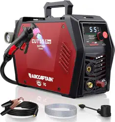
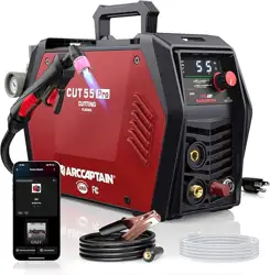
This is NEW Pro Serial Plasma Cutter, with advanced technology, perfect function and
high performance. This ultra-portable plasma cutting system is suitable for various
application needs. Additionally, the new Serial includes the latest remote control via APP.
Advanced digital control
The Plasma cutting machine CUT55 utilizes advanced MCU
intelligent digital control technology, with all major
components operated through software. Features like 2T/4T,
post-flow, and safety protection could easily read on digital
display. All digital control enhances cutting consistency and
stability while also making the cutter more compact and
enabling precise cutting.
Powerful cutting performance
This plasma cutter features a pilot arc function, enabling high frequency non-touch arc
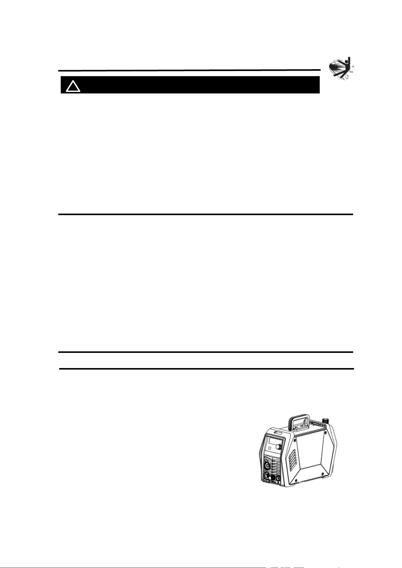
Figure 1
https://www.arccaptain.com/
4
starting. With this mode, the torch head doesn't require contact with the metal plate,
extending the lifespan of consumables and allowing for increased cutting thickness.
Additionally, plasma cutters with this function can cut through steel plates with rust and
paint on the surface.
Multi-scene cutting
The CUT55 is a versatile plasma cutter that can be used with either 120V or 240V AC
voltage. It operates using compressed air as the plasma gas source for cutting metals, so
ensure your air compressor is ready for use. The unit is designed to cut up to 3/5” inch
mild steel, but has the capability to cut other metals such as stainless steel, copper, cast
iron, and aluminum. With its simple operation and high cutting speed, it delivers smooth
cutting surfaces without requiring additional polishing.
Smart postflow
The gas will continue to flow for a little while
of postflow, The postflow will adjust to the
most suitable time based on the current size(0-5s), reduce unnecessary adjustment
operations.
2.2 Technical parameters
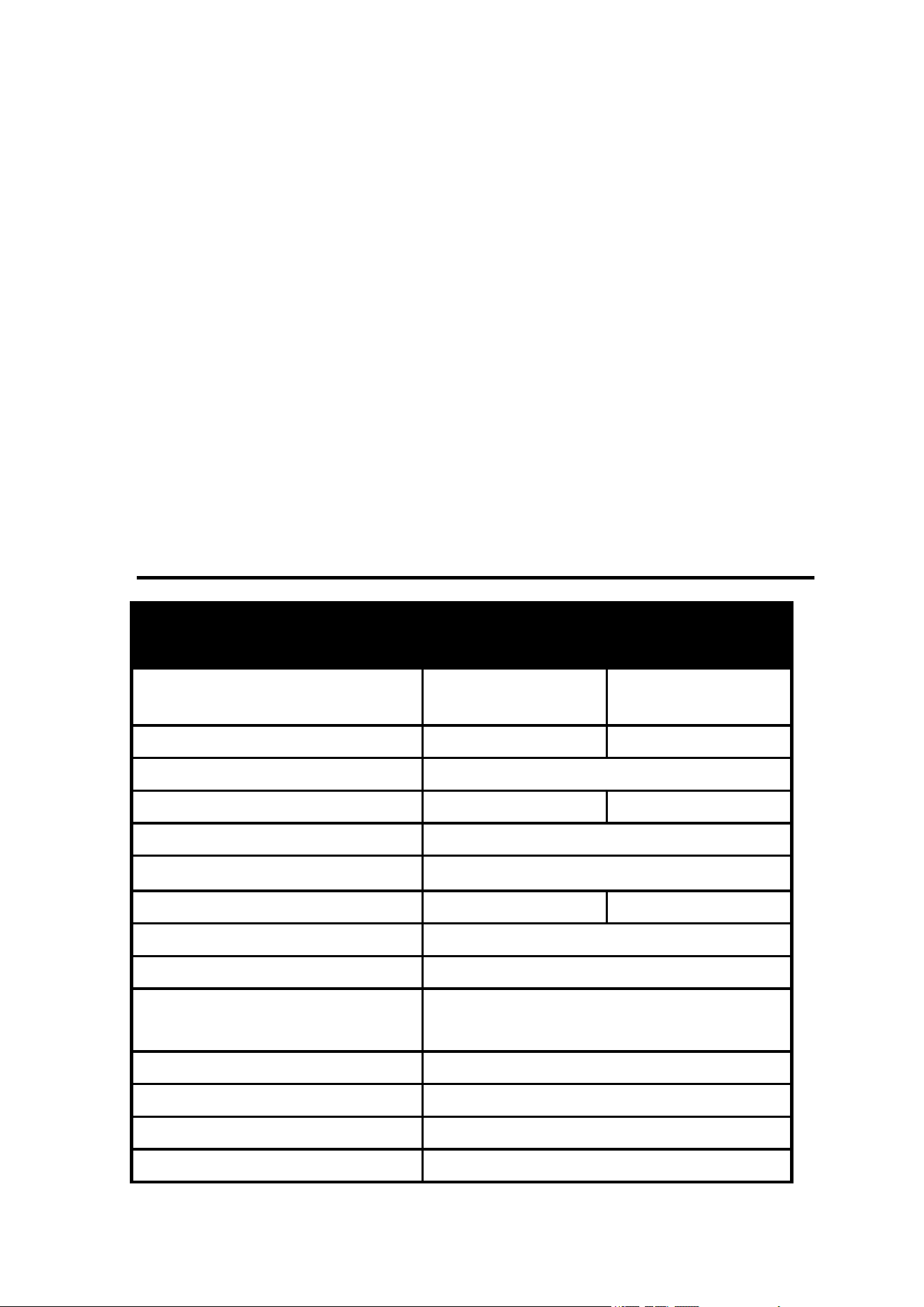
Items
Models
CUT55
Rated input power supply
Single-phase AC240V
50/60Hz
Single-phase AC120V
50/60Hz
Rated input capacity (kVA) 9.4 5.5
Power factor 0.7
Rated output (A/V) 55/102 35/94
Rated duty cycle (%) 60
No-load voltage (V) 330V
Output current range (A) 20~55 20~35
Arc ignition mode HF contact
Post-flow time (s) 5
Gas pressure range (Mpa/PSI)
0.2~0.5Mpa
29~72psi
Insulation grade H
Cooling mode Air cooling
Enclosure ingress protection IP21S
Efficiency (%) 85
https://www.arccaptain.com/
5
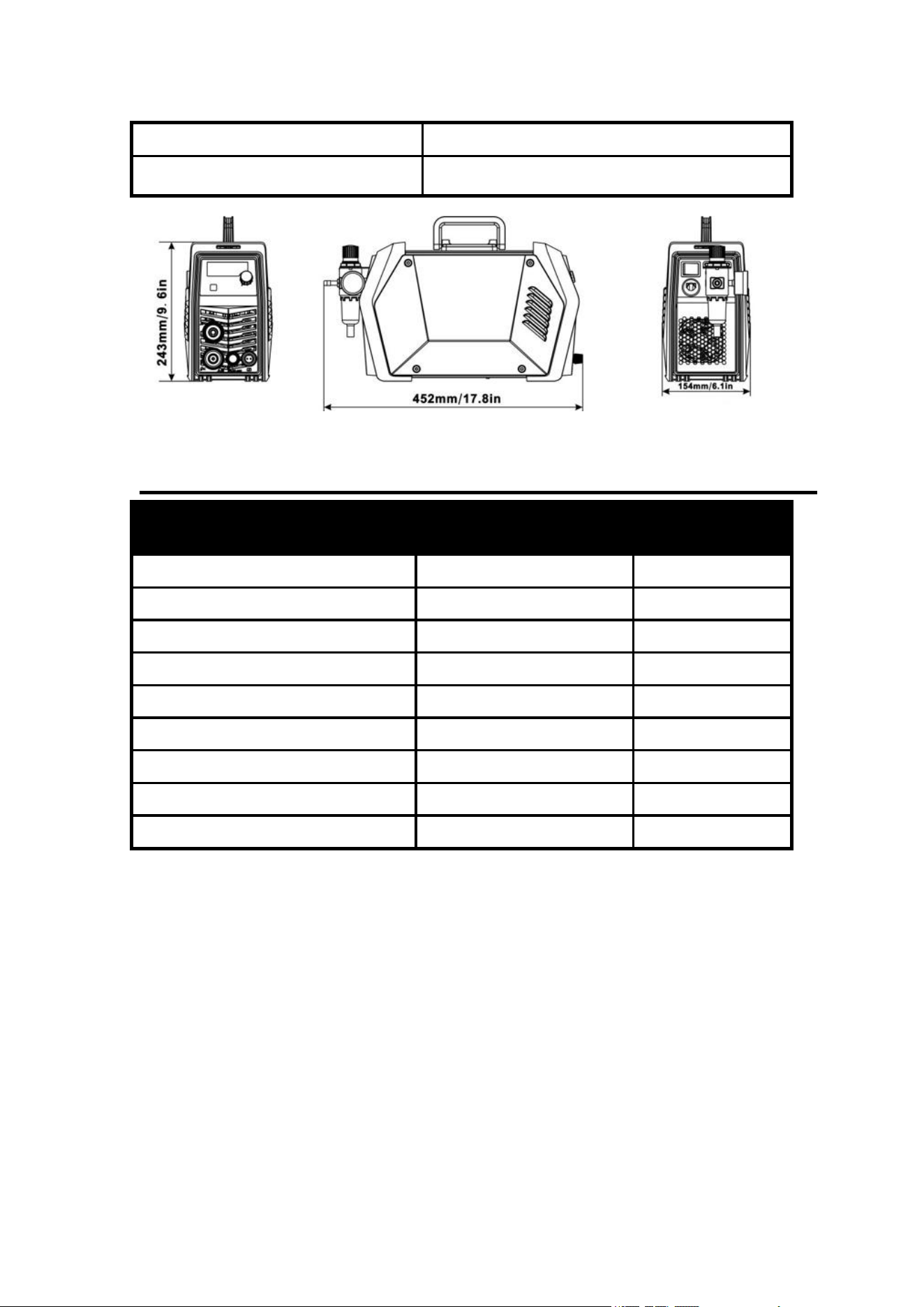
Figure 2: Size
2.3 Package
Name Specification Quantity (pcs)
Cutting machine CUT55 Pro 1
Air Compressor Filter Installed on the machine 1
Cutting torch & accessories AG-60 1
Ground clamp 200A-0.025in
2
DKJ 10-25 1
Gas hose 0.3*0.47in 1
Hose clamp / 2
Adapter 240V to 120V 1
Strap / 1
Operator’s manual CUT55 Operator’s manual 1
Dimensions(L*W*H) 17.8in*9.6in*6.1in/452*244*155mm
Weight (lb) 11.5lb/5.2kg
https://www.arccaptain.com/
6
3. INSTRUCTIONS
3.1 Panel Instruction
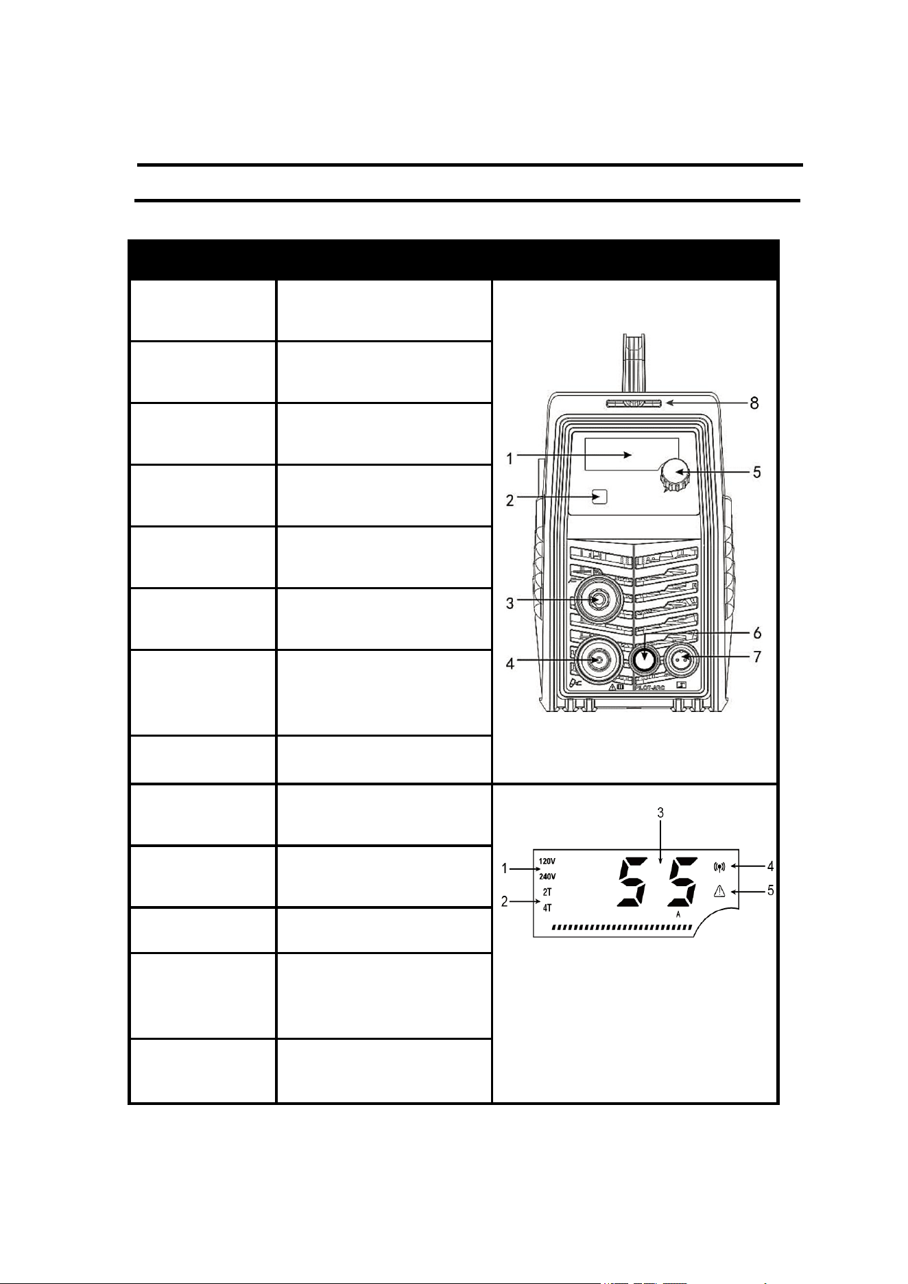
Part name Function Picture
1.Digital screen
To display the cutting
information
Figure 3 Front panel controls
2.Operation
mode button
For 2T/4T cutting mode
conversion
3.Earth cable
terminal
To connect the earth cable
4.Cutting torch
terminal
To connect the cutting torch
5.Current control
knob
To adjust the output current
6.Pilot arc
terminal
To connect pilot arc Line
7. Interface for
torch trigger (2
pin)
To connect the control
signal of cutting torch
8. Strap hole To connect the strap
1. Input voltage
Display the current input
voltage:120v/240v
Figure 4 Digital Display
2. 2T/4T
Display the current
operating mode
3. Current Display Current
4. Wireless
*
Display wireless signal light,
use App to control the
machine
5. Alarm lights
Abnormal alarm display
light
https://www.arccaptain.com/
7
* For more detailed information about the connection and operational
guidelines for the ARCCAPTAIN APP, please visit arccaptain.com and
explore the resources available there.
3.2 Nameplate
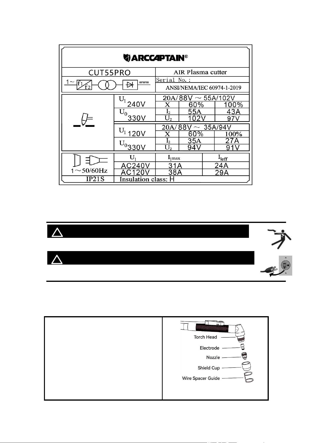
On the machine, there is a plate that includes all the operating specifications for your new
unit. The serial number of the product is also found on this plate.
The duty cycle rating of a plasma cutter defines how long the operator can cut and how
long the cutter must rest and be cooled. Duty cycle is expressed as a percentage of 10
minutes and represents the maximum cutting time allowed. The balance of the 10-minute
cycle is required for cooling.
For example, a plasma cutter has a duty cycle rating of 60% at the rated output of 55A.
This means with that machine: you can cut at 55 A output for six (6) minutes out of 10 with
the remaining four (4) minutes required for cooling. The duty cycle of your new plasma
cutter can be found on the data plate affixed to the machine. It looks like the diagram
below.
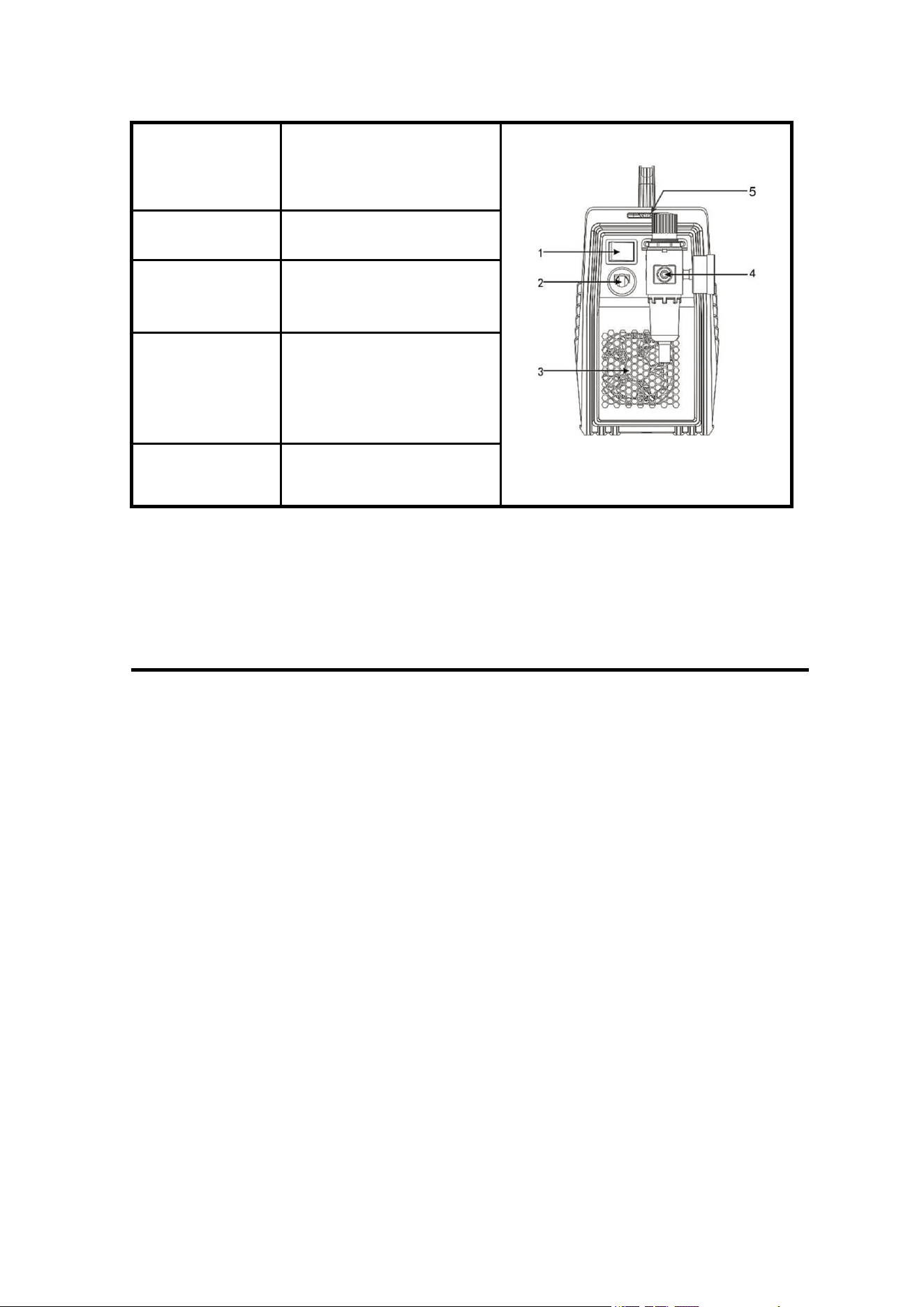
1.Power switch
To control the ON/OFF of
the input power of the
machine
Figure 5 Back panel controls
2.Cable For power supply input
3.Cooling fan
For heat dissipation through
forced air cooling
4.Air reducer
valve
To adjust the pressure of
the input air. The hose will
connect to here by hose
clamp.
5.Strap hole To connect the strap
https://www.arccaptain.com/
8
Figure 6: Nameplate
4.INSTALLATION AND CONNECTION
! WARINING BEWARE OF ELECTRIC SHOCK!
Check and follow the instructions listed in the “Safety” section of this manual.
! WARINING DO NOT set up without SWITCH OFF !
4.1 Installation of the cutting torch
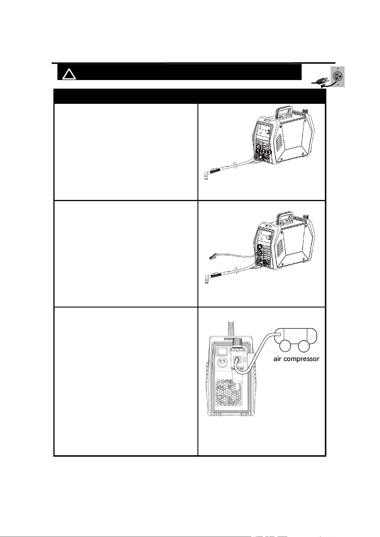
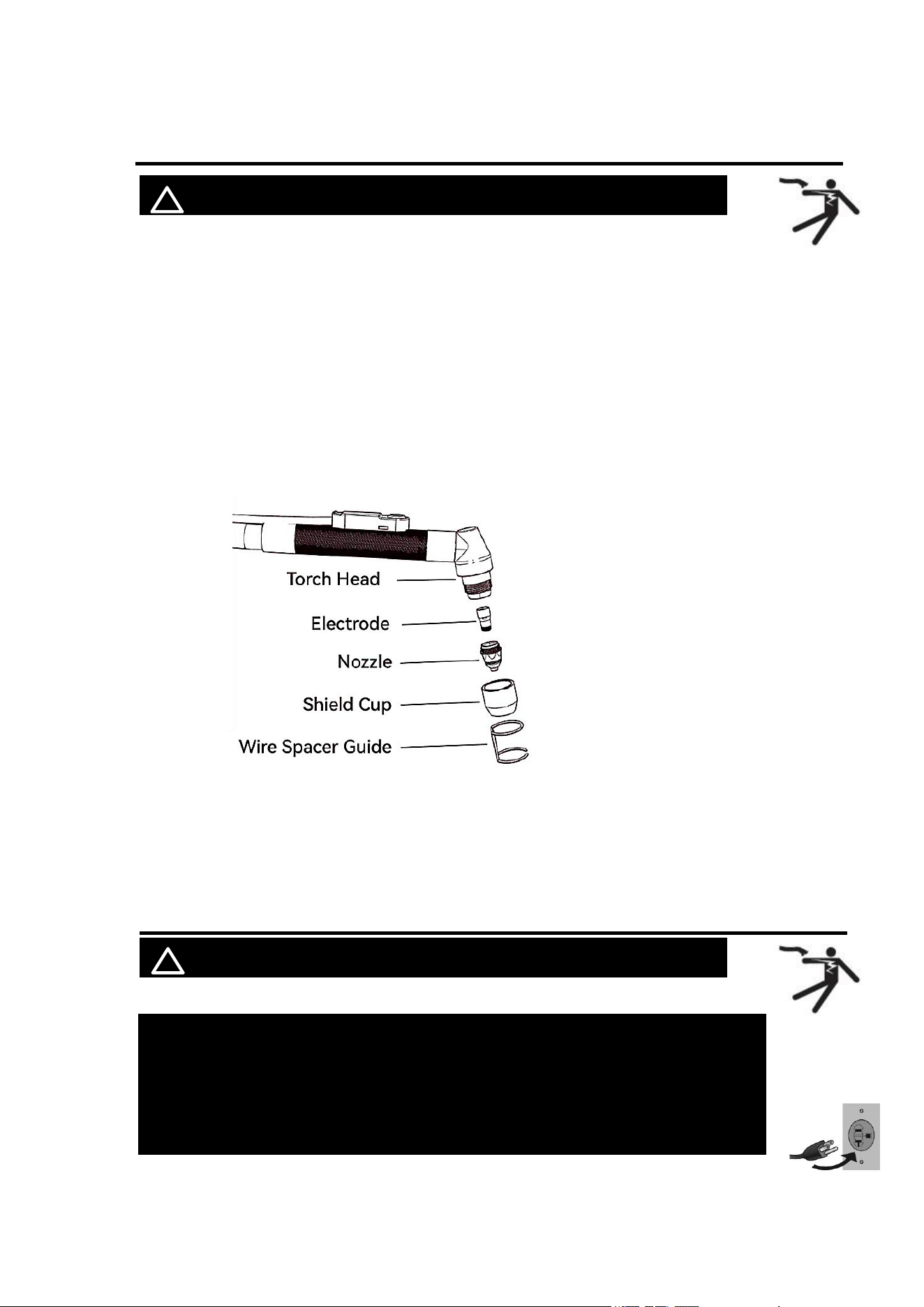
Check the torch for proper assembly. Install proper torch parts for the desired application
(Refer to the following Torch head figure).
NOTE: The power supply will NOT operate unless the torch shield cup is fully seated
against the Parts in Place pins in the torch head.
1. Connect the Electrode into the Torch
Head.
2. Connect the Nozzle into the Torch
Head.
3. Connect the Shield Cup into the Torch
Head.
4. Connect the Wire Spacer Guide onto
the Shield Cup
Figure 7 cutting torch head
https://www.arccaptain.com/
9
4.2 Installation of the Connection Cable
! WARINING DO NOT set up without SWITCH OFF !
Description
Picture
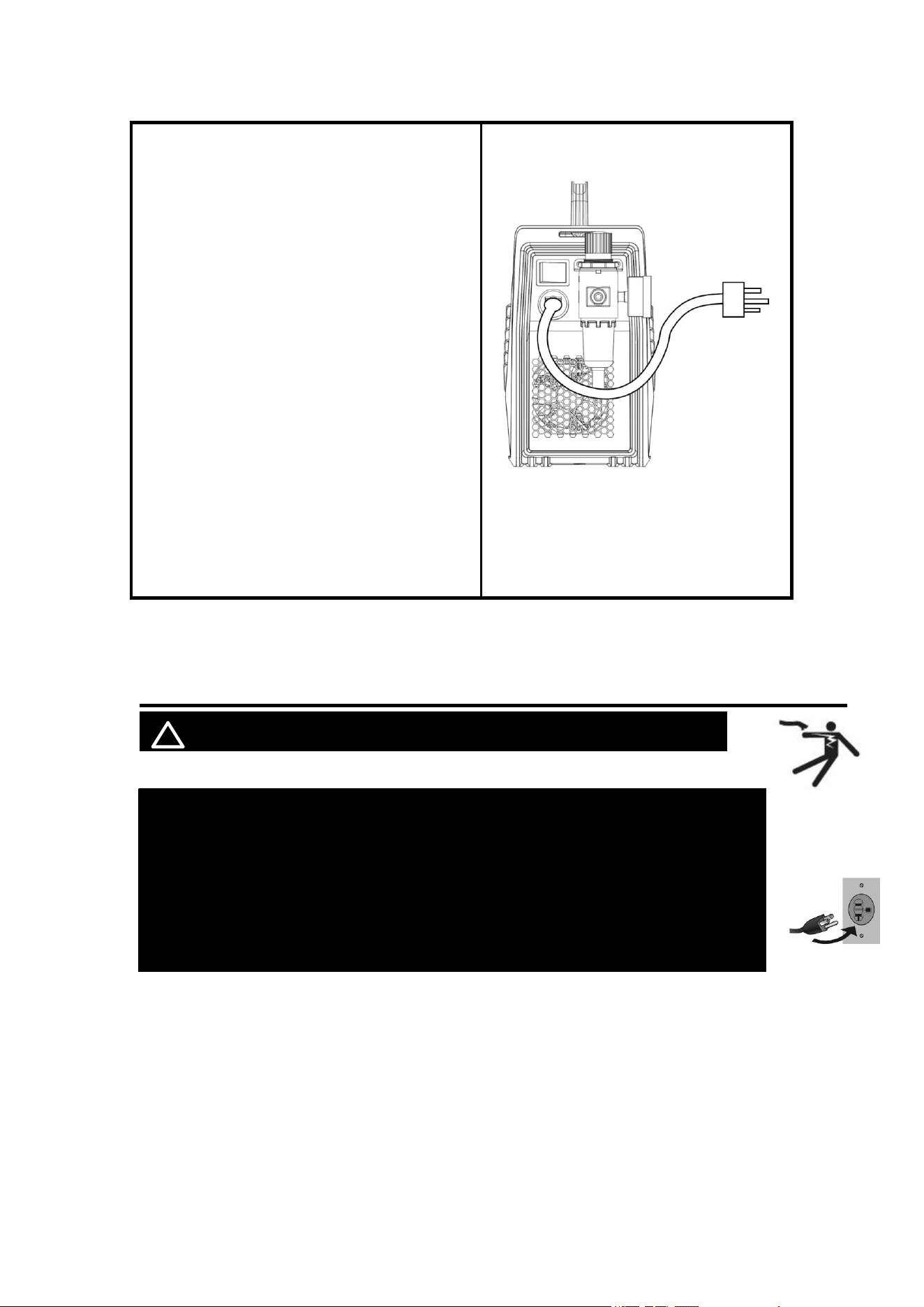
1.
Connect the Cutting gun to “-” Negative
polarity and aviation plug
NOTICE:
The Cutting gun connector MUST be tightly
connected to the socket to avoid power
short circuit.
Figure 8 Connection of cutting torch
2. Connection of earth cable
Insert the quick plug on the earth cable into
the terminal and tighten it clockwise.
NOTICE:
The ground clamp connector MUST be
tightly connected to the socket to avoid
power short circuit.
Ensure the ground clamp is connected on
clean, bare metal (not rusty or painted).
Figure 9 Connection of earth cable
3. Connection of air compressor
The CUT55 requires compressed air to be
attached to the unit. Use a hose clamp to
tighten the gas hose to avoid air leakage
NOTICE:
The input air pressure mini-mum must be 72.5
PSl, 5 Bar and must not exceed150 PSl, 10.3
Bar. An air regulator is included with the unit
with optimum pressure setting set to 57.5 PSl,
4 Bar.
The unit is also equipped with an air filter
which captures water and oil vapor. The vapor
collected can be drained out of the bottom of
the unit by turning the drain button.
Figure 10 Connection of air
compressor
https://www.arccaptain.com/
10
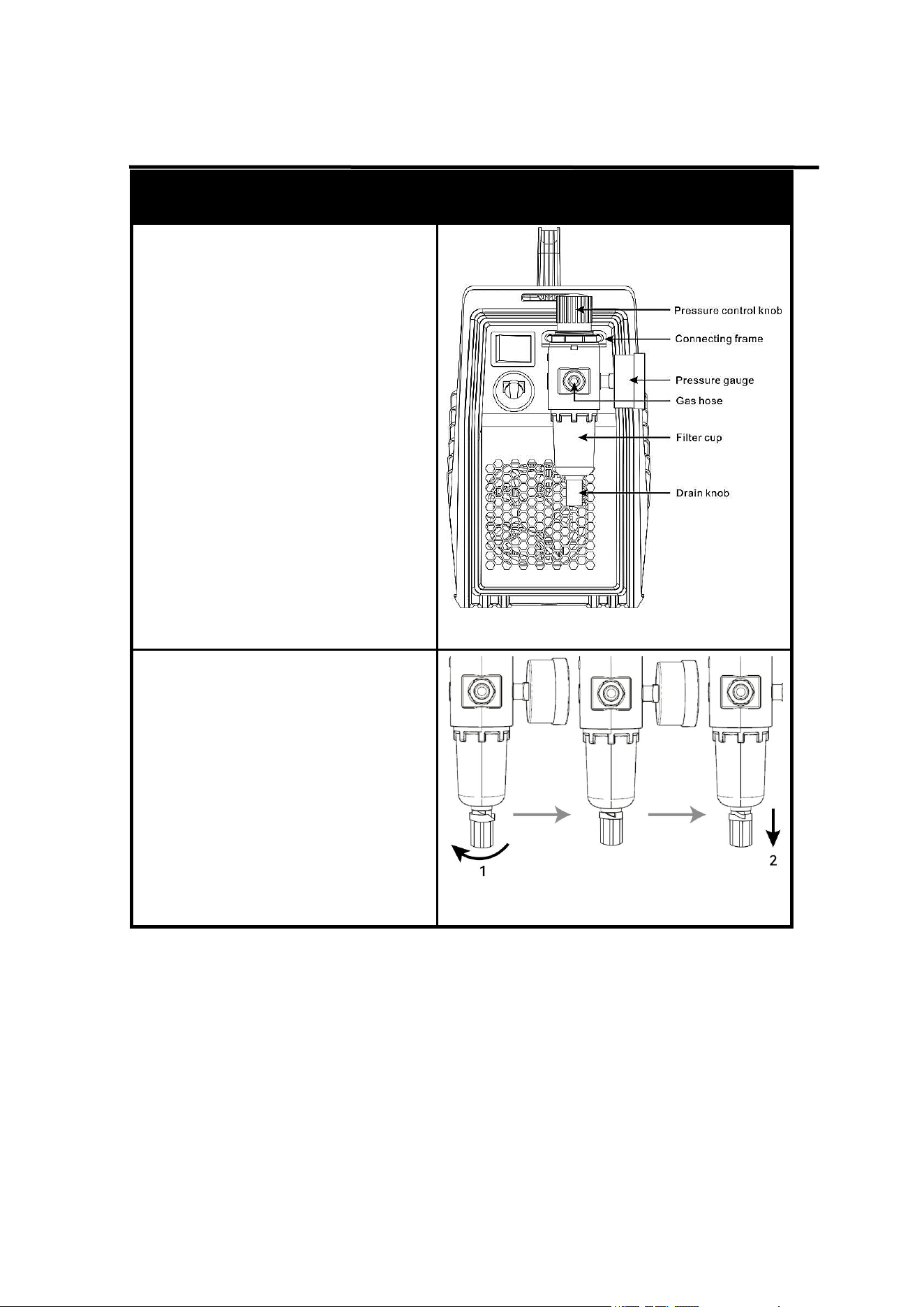
4.
Connection of input power
The CUT55 PRO operates in 240V or 120V
power supply. Plug the Power Cord into a
properly grounded. Set Cutting Gun down on
nonconductive, nonflammable surface away
from any grounded objects. And then then turn
the Power Switch ON. The fan should start.
The Digital screen should turn on.
NOTICE:
Adjust the Voltage Switch to match the outlet
voltage:
For 120VAC, attach the provided adapter to
the Power Cord.
For 240VAC, do not use the adapter.
Plug the Power Cord into a properly grounded
and rated receptacle matching the plug and
selected voltage.
Need to be connected to circuits with 50A and
above circuit breakers
Figure 11 Connection of input power
5. OPERATION
! WARINING BEWARE OF ELECTRIC SHOCK!
NOTICE:
To prevent serious injury from fire or electric shock:
1.DO NOT touch anything, especially not the ground clamp, with the
gun or cutting wire or an arc will be ignited.
2. DO NOT touch plasma cutter Components while it is plugged in.
https://www.arccaptain.com/
11
5.1 Operation of the reducer valve
Description
Picture
Steps for reducer setting are as
follows:
1. lift the pressure control knob
upward. adjust the gas pressure
to the desired value by rotating
the knob (rotate to “+” direction to
increase gas pressure; rotate to
“-” direction to reduce gas
pressure);
2. press down the pressure control
knob to get the knob locked.
Figure 12 Installation of the reducer valve
Release water and oil vapor or gas
WARINING: DO NOT set up without
SWITCH OFF !
1. Turn the knob to the left to open the
drain knob.
2. Pull the drain knob down to
Release water and oil vapor or gas.
NOTICE:
The drain knob needs to be turned off
before cut55 can be used properly.
Figure 13 Release water and oil vapor or
gas
https://www.arccaptain.com/
12
5.2 Operation method
! WARINING BEWARE OF ELECTRIC SHOCK!
Description Picture
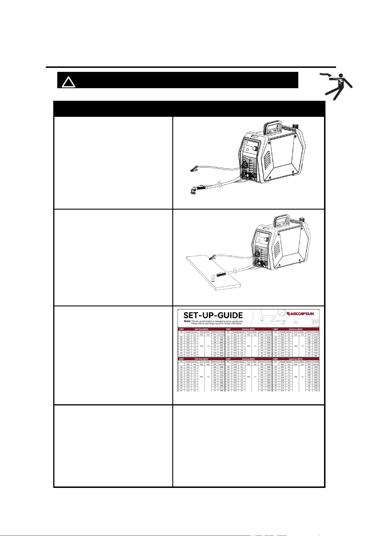
1. Confirm that cut55 has been
installed and operated correctly, refer
to sections 4 and 5
Figure 14 Installation
2. Clamp the Ground clamp onto the
workpiece, The Ground clamp must
be securely connected to the
workpiece.
Figure 15 Clamp the Ground clamp
3. Set the output current control knob
at maximum position for higher
cutting speed and less dross
formation. Reduce the current, if
desired to reduce the cut width,
heat affected zone or travel speed
as required.
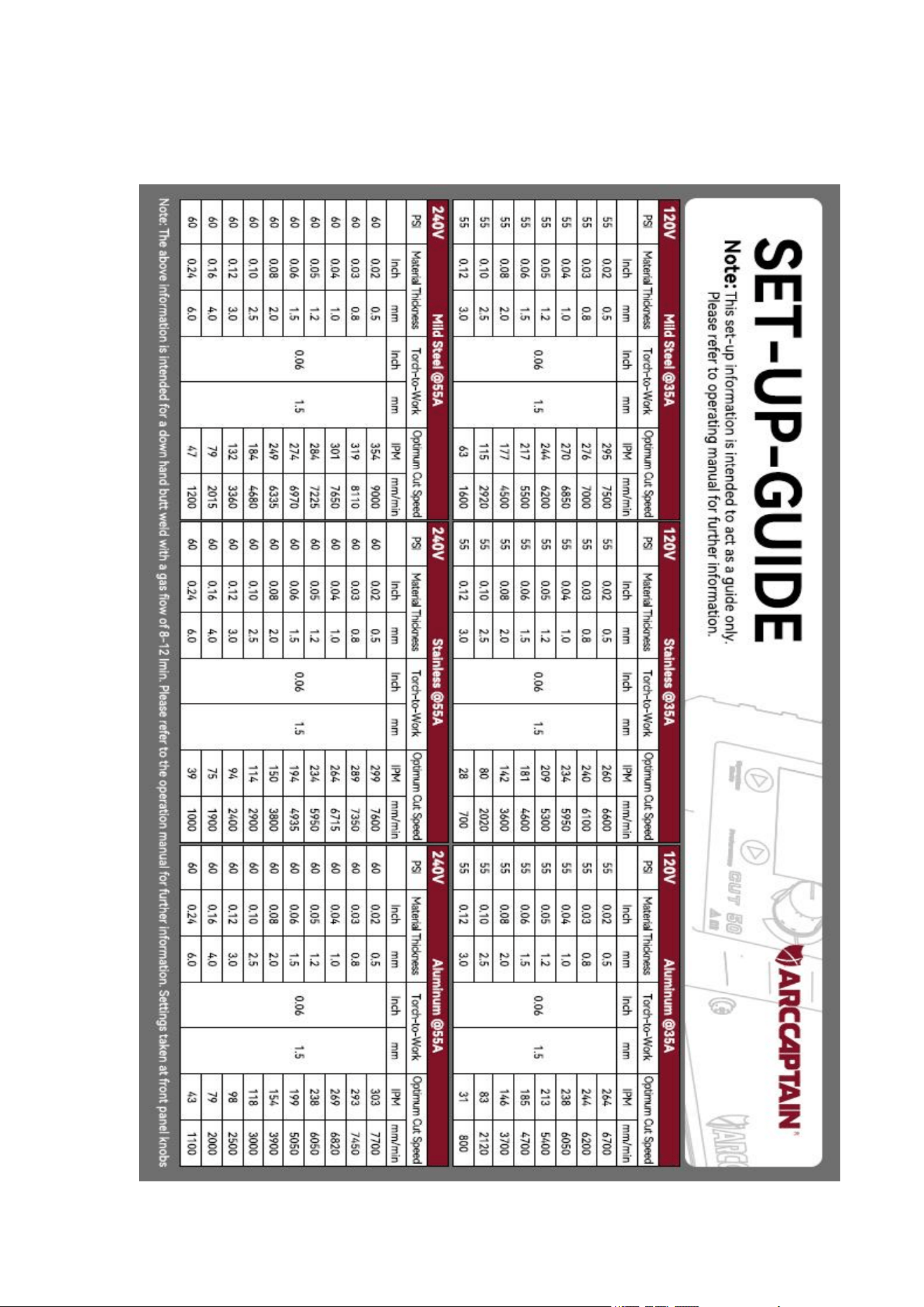
4. You can refer to Appendix 1 to set
cutting parameters
Figure 16 refer to Appendix 1
5. 2T/4T mode select 2T (2 touch) mode:
Press the trigger to start the cutting current
Release trigger to stop the cutting current.
4T (4 touch) mode:
Press trigger to start cutting
Release trigger during cutting.
Press and release trigger to shut cutting
current off.
https://www.arccaptain.com/
13
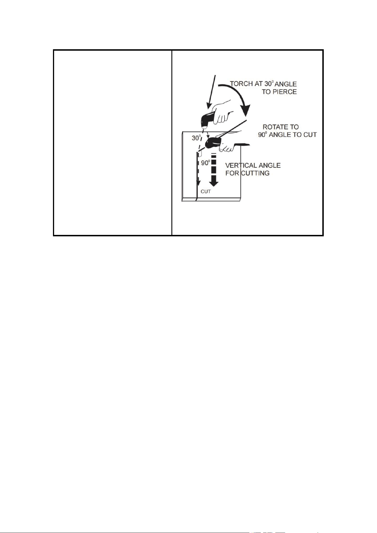
1. When ready to cut, place the torch
near the work, make certain all safety
precautions have been taken and pull
the trigger. The pilot arc will start.
2. Pierce the work piece by slowly
lowering the torch onto the metal at a
30° angle away from the operator.
This will blow the dross away from the
torch nozzle. Slowly rotate the torch
to vertical position as the arc
becomes deeper.
NOTE: Graphics shown are for
understanding torch angles for best
results – the distances from the
workpiece are exaggerated. In actual
operation, the nozzle should be held
just above the work piece surface.
Figure 17 Cutting operation
NOTE
For better torch control, it is acceptable to let the nozzle drag along the work piece surface.
This will shorten nozzle life. Also, it is acceptable to place a non-conductive torch guide on
the work piece in order to achieve a cleaner cut
• When the trigger is released, the arc will stop. The gas will continue to flow for 5 seconds
of postflow. If the trigger is activated within this time period
• If the dross is difficult to remove, reduce the cutting speed. High speed dross is more
difficult to remove than low speed dross.
• The right side of the cut is more square than the left as viewed along the direction of
travel.
• Clean spatter and scale from the nozzle frequently.
Parts in place
Cutting torch reference Figure 7 cutting torch head. If the accessories of cutting
torch need to be replaced, please log in to the official website:
WWW.ARCCAPTAIN.COM
• Check the assembly of the torch consumables. If they are not properly in place, the
machine will not start. Make sure that the shield cup is hand tight. Do not use pliers
or over tighten.
• Check the conditions of the inside of the nozzle. If debris has collected, rub the
electrode on the inside bottom of the nozzle to remove any oxide layer that may have built
up. Refer to the “Routine Maintenance Section".
https://www.arccaptain.com/
14
• Check the condition of the electrode. If the end has a crater-like appearance, replace it
along with the nozzle. The maximum wear depth of the electrode is approximately .062”. A
green and erratic arc will indicate definite electrode failure and the electrode should be
replaced immediately.
• Replace the nozzle when the orifice exit is eroded away or oval shaped.
Pilot arc discussion
The CUT has a smooth, continuous pilot arc. The pilot arc is only a means of transferring
the arc to the workpiece for cutting. Repeated pilot arc starts, in rapid succession, is not
recommended as these starts will generally reduce consumable life. Occasionally, the
pilot arc may sputter or start intermittently. This is aggravated when the consumables are
worn or the air pressure is too high.
Always keep in mind that the pilot arc is designed to transfer the arc to the workpiece and
not for numerous starts without cutting. When the pilot arc is started, a slight impulse will
be felt in the torch handle. This occurrence is normal and is the mechanism which starts
the plasma arc. This impulse can also be used to help troubleshoot a "no start" condition.
5.3 Notes for cutting operation
! WARINING BEWARE OF ELECTRIC SHOCK!
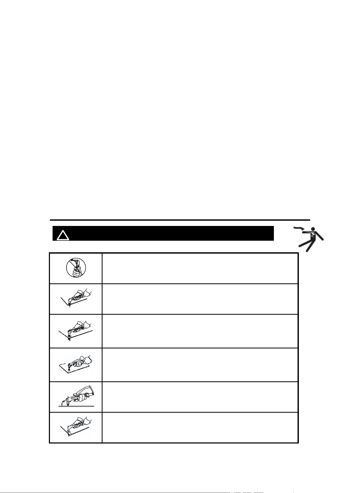
It is recommended not to ignite the arc in the air if not necessary, for it
will shorten the lifespan of the electrode and nozzle of the torch.
It is recommended to initiate the cutting from the edge of workpiece,
unless penetration is needed.
Ensure spatters fly from the bottom of workpiece while cutting. If
spatters fly from the top of workpiece, it indicates that the workpiece
can not be fully cut because the cutting torch is moved too fast or the
cutting current is too low.
Keep the nozzle slightly touching the workpiece or keep a short
distance between the nozzle and workpiece. If the torch is pressed
against the workpiece, the nozzle may stick to the workpiece, and
smooth cutting is unavailable.
For cutting round workpiece or to meet precise cutting requirement,
molding board or other assistant tools are needed.
It is recommended to pull the cutting torch while cutting.
https://www.arccaptain.com/
15
Keep the nozzle of cutting torch upright over the workpiece, and check
if the arc is moving with the cutting line. If the space is not enough,
don’t bend the cable too much, step on or press upon the cable to
avoid suffocating of gas flow. The cutting torch may be burned
because the gas flow is too small. Keep the cutting cable away from
edge tools.
Clean up the spatters on the nozzle timely, for it will affect the cooling
effect of the nozzle. Clean up the dust and spatters on the torch head
after using everyday to ensure good cooling effect.
The workpiece is not cut fully. This may be caused by:
1. The cutting current is too low.
2. The cutting speed is too high.
3. The electrode and nozzle of the torch are burned.
4. The workpiece is too thick.
Molten slag drops from the bottom of workpiece. This may be caused by:
1. The cutting speed is too low.
2. The electrode and nozzle of the torch are burned.
3. The cutting current is too high.
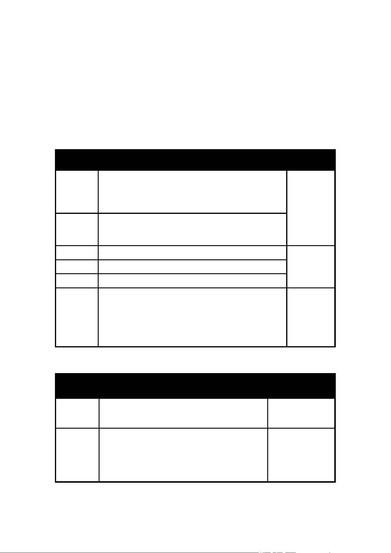
5.4 Cutting parameters table
! WARINING BEWARE OF ELECTRIC SHOCK!
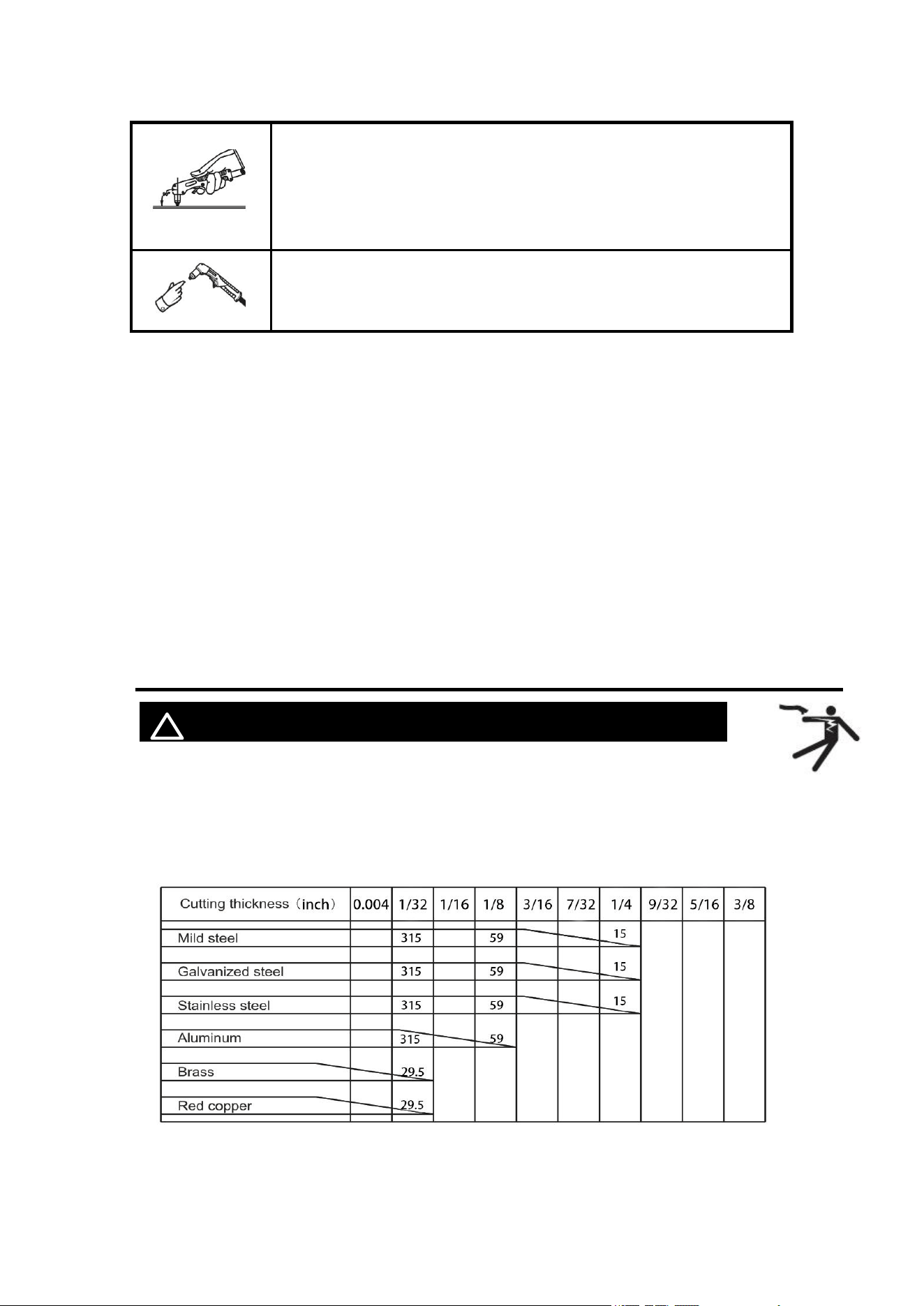
Select proper current according to the cutting parameters table, workpiece material,
cutting thickness and cutting speed, etc. (The figure in the below table is an
approximation.)
Figure 18 Cutting speed (in/min) when cutting current is 55A
https://www.arccaptain.com/
16
5.5 Replacement of electrode and nozzle
! WARINING BEWARE OF ELECTRIC SHOCK!
When the phenomena below occur, the electrode and nozzle should be replaced.
Otherwise, there will be strong arc in the nozzle, which will break down the electrode and
the nozzle, or even burn the torch. Nozzles of different models are different, so ensure the
nozzle is of the same model when replacing it.
1. Electrode wear>0.06in
2. Distortion of the nozzle
3. Cutting speed declining, arc with green flame
4. Difficult in arc ignition
5. Irregular cut
Figure 19 Exploded view of cutting torch
If the accessories of cutting torch need to be replaced, please log in to the official
website: WWW.ARCCAPTAIN.COM
6.MAINTENANCE
! WARINING BEWARE OF ELECTRIC SHOCK!
NOTICE:
The power of the switching box and the cutting machine should be
shut down before daily checking (except appearance checking
without contacting the conductive body) to avoid personal injury
accidents such as electric shock and burns.
https://www.arccaptain.com/
17
Tips:
1. Daily checking is very important in keeping the high performance and safe operation
of this cutting machine.
2. Do daily checking according to the table below, and clean or replace components
when necessary.
3. In order to ensure the high performance of the machine, please choose components
provided or recommended by dealer when replacing components.
4.
Daily checking of the cutting machine
Items Checking requirements Remarks
Front panel
Whether any of the components are damaged or loosely
connected;
Whether the output quick sockets are tightened;
Whether the abnormity indicator illuminates.
If unqualified,
check the
interior of the
machine, and
tighten or
replace the
components.
Back panel
Whether the input power cable and buckle are in good
condition;
Whether the air intake is unobstructed.
Cover
Whether the bolts are loosely connected.
If unqualified,
tighten or
replace the
components.
Side plates
Whether the side plate is loosely fixed.
Chassis
Whether the screws are loosely connected.
Routine
Whether the machine enclosure has color fading or
overheating problems;
Whether the fan sounds normal when the machine is
running;
Whether there is abnormal smell, abnormal vibration or
noise when the machine is running.
If abnormal,
check the
interior of the
machine.
Daily checking of the cables
Items Checking requirements Remarks
Earth cable
Whether the grounding wires (including workpiece
GND wire and cutting machine GND wire) break off.
If unqualified,
tighten or replace
the components.
Cutting
cable
Whether the insulating layer of the cable is worn, or
the conductive part of the cable is exposed;
Whether the cable is drawn by an external force;
Whether the cable connected to the workpiece is well
connected.
Use appropriate
methods according
to the work site
situation to ensure
safety and normal
cutting.
https://www.arccaptain.com/
18
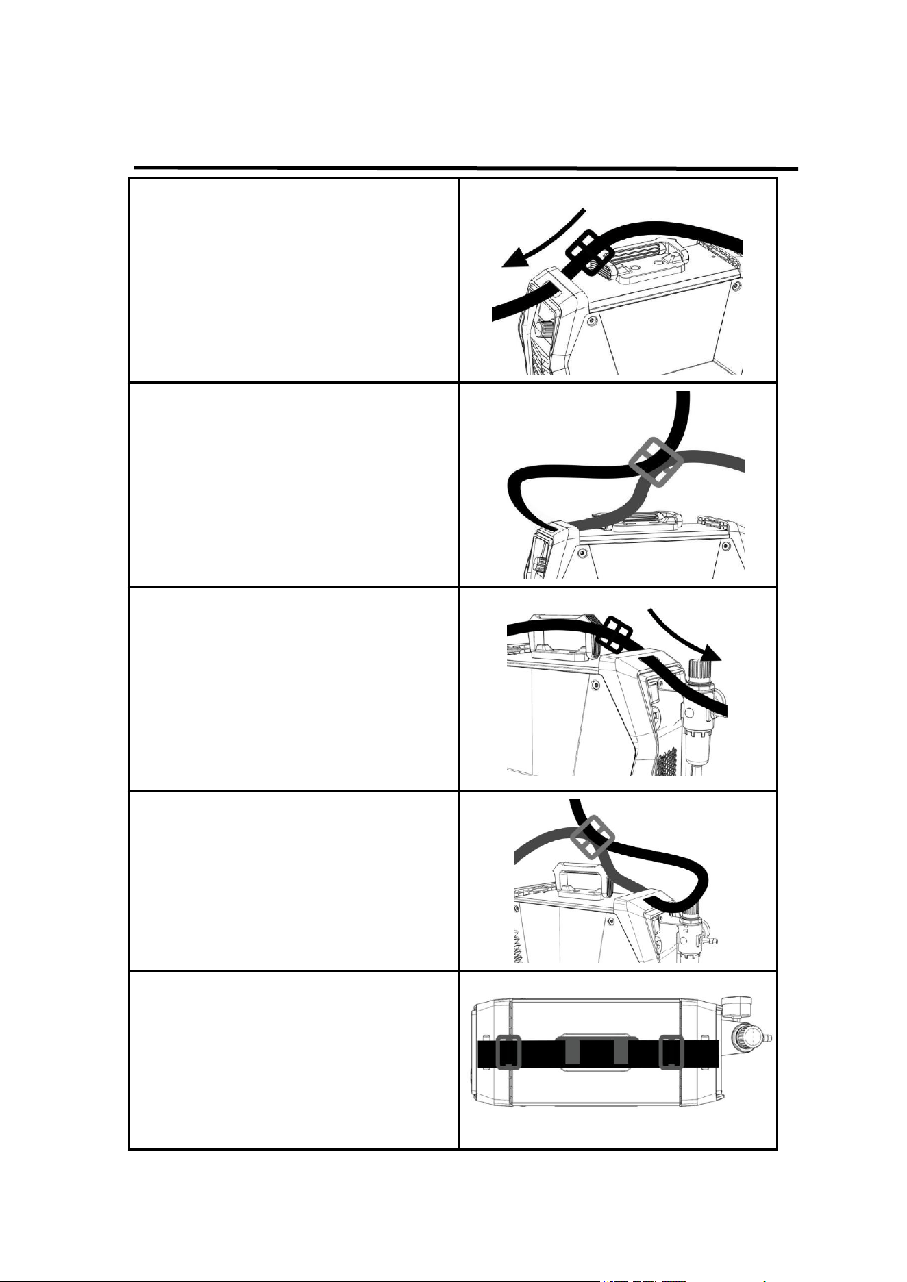
7.STRAP INSTALLATION
Step 1: Thread the strap through the strap
hole in front of the welder.
Step 2: Thread the strap through the nylon
buckle as shown in the diagram.
Step 3: Thread the strap through the strap
hole in back of the welder.
Step 4: Thread the strap through the nylon
buckle as shown in the diagram.
Step 5: The strap installation is complete.
https://www.arccaptain.com/
19
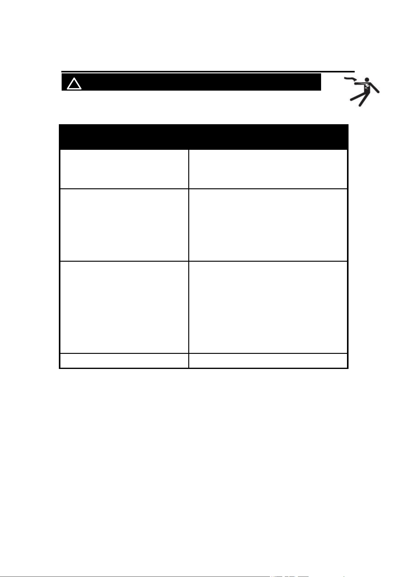
8. TROUBLESHOOTING
! WARINING BEWARE OF ELECTRIC SHOCK!
The abnormity indicator on the front panel would illuminate in case of any
failures inside the cutting machine.
Malfunction phenomena
Cause and solution
Turn on the machine, the LED screen
illuminates, the control PCB keys do
not function, and there is no response
when pushing the torch trigger.
The cutting machine crashes: Shut down the
machine, and restart it.
the LED Display E-1 or E-2
1.
E-1 overheat protection: machine is under
overheat protection and stops working until
E60 disappears
2. E-2 over-current protection:internal
components are damaged, please contact
dealer for help
Turn on the machine, the LED screen
illuminates, and the fan works. When
pushing the torch trigger, the solenoid
valve functions, but there is no HF
discharge rustling.
The arc ignition part fails:
1.
The inter electrode distance of the
discharge nozzle is too long.
2.
There is leakage of the HF capacitor
222/10KV.
3.
The mosfet or the optocoupler on the HF
board is damaged.
4. The input voltage is too low.
Arc can not be ignited.
The air pressure is overly high or overly low.
https://www.arccaptain.com/
20
Appendix 1
https://www.arccaptain.com/