
User manual
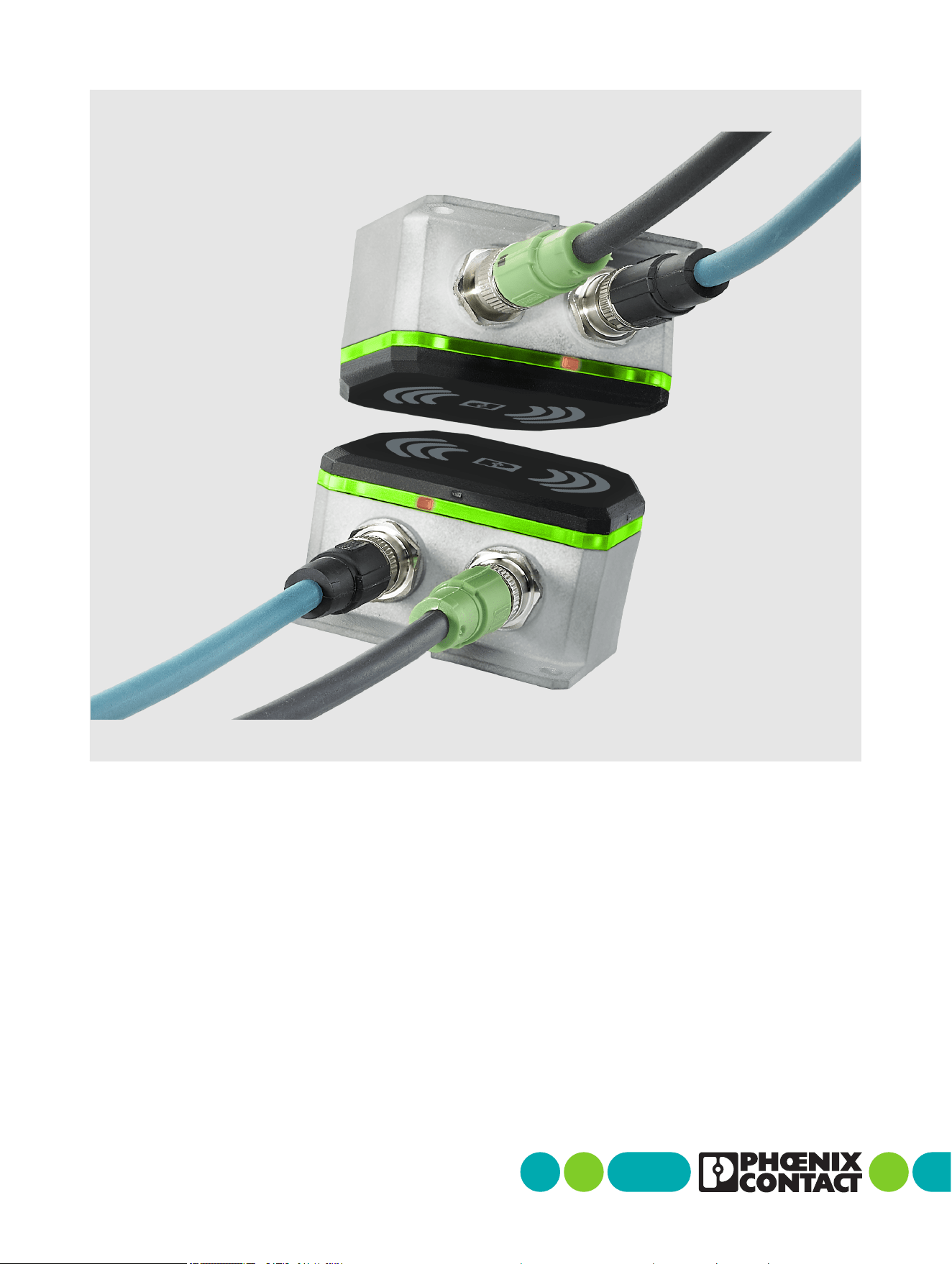
NearFi couplers
for contactless power and
real-time Ethernet data transmission

2026-04-27
Phoenix Contact GmbH & Co. KG • Flachsmarktstraße 8 • 32825 Blomberg • Germany
phoenixcontact.com
110718_en_02
NearFi couplers for contactless power and real-time Ethernet
data transmission
This user manual is valid for:
Designation Item No.
NEARFI 2200 B 1433050
NEARFI 2200 R 1433049
NEARFI 200 B 1433047
NEARFI 200 R 1433046
NEARFI 300 B 1464614
NEARFI 300 R 1509989
NEARFI 2000 B 1433041
NEARFI 2000 R 1433040
User manual
UM EN NEARFI, Revision 02

Table of contents
110718_en_02 Phoenix Contact 3 / 102
Table of contents
1 For your safety .............................................................................................................................5
1.1 Identification of warning notes...............................................................................5
1.2 Qualification of users ..............................................................................................5
1.3 Field of application of the product..........................................................................6
1.4 Safety notes.............................................................................................................6
1.5 Protection against tampering..................................................................................7
1.6 User documentation................................................................................................8
1.7 UL notes...................................................................................................................9
2 FCC approval ............................................................................................................................. 10
2.1 Part15 .................................................................................................................. 10
2.2 Part18 .................................................................................................................. 11
2.3 Intended use description for industrial inductive couplers................................ 11
2.4 Installation instructions for applications using Nearfi base units
(NEARFI 2200 B, NEARFI 300 B, NEARFI 200 B)............................................... 12
2.5 Part 15, 18 ............................................................................................................ 14
3 Transport, storage, and unpacking ........................................................................................... 15
3.1 Transport .............................................................................................................. 15
3.2 Storage.................................................................................................................. 15
3.3 Unpacking............................................................................................................. 16
4 Product description ................................................................................................................... 17
4.1 Functional principle.............................................................................................. 18
4.2 Installation examples........................................................................................... 19
4.3 Compatibility ........................................................................................................ 33
4.4 Basic circuit diagram............................................................................................ 34
4.5 Function elements................................................................................................ 38
4.6 DIP switches......................................................................................................... 40
4.7 Ethernet ................................................................................................................ 43
4.8 Switch-on time (operational readiness time)...................................................... 44
4.9 Positioning of the devices .................................................................................... 45
4.10 Obstacles in the air gap........................................................................................ 49
4.11 Foreign objects in the air gap............................................................................... 49
4.12 Minimum clearances ............................................................................................ 50
4.13 Installation in metal ............................................................................................. 50

NEARFI
4 / 102 Phoenix Contact
110718_en_02
4.14 Coupling the base and remote couplers.............................................................. 51
4.15 Derating ................................................................................................................ 53
5 Installation ................................................................................................................................ 58
5.1 Mounting and removal.......................................................................................... 58
5.2 Connecting cables ................................................................................................ 62
5.3 Startup and maintenance..................................................................................... 72
6 Troubleshooting ........................................................................................................................ 73
6.1 Diagnostic LEDs.................................................................................................... 73
7 Device replacement, device defect and repair ......................................................................... 80
7.1 Device replacement ............................................................................................. 80
7.2 Device defect and repair ...................................................................................... 80
8 Maintenance and disposal ........................................................................................................ 81
8.1 Maintenance ......................................................................................................... 81
8.2 Disposal ................................................................................................................ 81
9 Technical data ........................................................................................................................... 82
9.1 Ordering data........................................................................................................ 82
9.2 Technical data ...................................................................................................... 85
9.3 Dimensions ........................................................................................................... 94
A Appendix .................................................................................................................................... 97
A 1 List of figures ........................................................................................................ 97
A 2 List of tables ......................................................................................................... 99
B Revision history........................................................................................................................ 100

For your safety
110718_en_02 Phoenix Contact 5 / 102
1 For your safety
1.1 Identification of warning notes
1.2 Qualification of users
The use of products described in this manual is oriented exclusively to:
– Electrically skilled persons or persons instructed by them. The users must be familiar
with the relevant safety concepts of automation technology as well as applicable
standards and other regulations.
This symbol indicates hazards that could lead to personal injury.
There are three signal words indicating the severity of a potential injury.
DANGER
Indicates a hazard with a high risk level. If this hazardous situation is not
avoided, it will result in death or serious injury.
WARNING
Indicates a hazard with a medium risk level. If this hazardous situation is not
avoided, it could result in death or serious injury.
CAUTION
Indicates a hazard with a low risk level. If this hazardous situation is not
avoided, it could result in minor or moderate injury.
This symbol together with the NOTE signal word warns the reader of actions
that might cause property damage or a malfunction.
Here you will find additional information or detailed sources of information.
This symbol indicates a risk of security problems in industrial automation. Here
you will find information on how to prevent security problems.

NEARFI
6 / 102 Phoenix Contact
110718_en_02
1.3 Field of application of the product
1.3.1 Intended use
The devices are designed for use in industrial environments.
1.3.2 Product changes
Modifications to the hardware and firmware of the device are not permitted.
Incorrect operation or modifications to the device can endanger your safety or damage
the device. Do not repair the device yourself. If the device is defective, please contact
Phoenix Contact.
1.4 Safety notes
WARNING:
Observe the following safety notes when using the device.
• Installation, operation, and maintenance may only be carried out by qualified electri-
cians. Follow the installation notes as described.
• When installing and operating the device, observe the applicable regulations and
safety directives (including national safety directives), as well as the generally recog-
nized engineering rules.
• Observe the safety information, conditions, and limits of use specified in the product
documentation. Comply with them.
• Mounting and electrical installation must correspond to the state of the art.
• The device must not be opened or modified apart from the configuration of the DIP
switches. Do not repair the device yourself; replace it with an equivalent device. Re-
pairs may only be carried out by the manufacturer. The manufacturer is not liable for
damage resulting from non-compliance.
Installation
• The device is designed exclusively for operation with safety extra-low voltage
(SELV/PELV) from a class ES1 “electrical energy source” in accordance with
EN/IEC 62368-1 and VDE 0868-1. The device may only be connected to devices that
satisfy the conditions of class ES1 in accordance with EN/IEC 62368-1.
• Make sure that the wiring on the primary side and the secondary side is adequately
dimensioned.
• Note the voltage drop across the cable. In the event of undervoltage, the devices can
no longer function.
• The connection parameters, such as the required stripping lengths for the wiring, can
be found in the installation information for the respective field-side circular connec-
tor.

For your safety
110718_en_02 Phoenix Contact 7 / 102
Installation location
CAUTION: Hot surface
The device housing can become hot. The device may remain hot even after discon-
necting the supply voltage.
• Ensure sufficient touch protection.
• Prevent inadvertent contact by using a mechanical barrier or clearly visible warn-
ing signs.
• Select the installation location so that metal objects cannot enter the air gap be-
tween the base and the remote.
• The die-cast housing and the device-side circular connectors satisfy the require-
ments of degree of protection IP65.
• Put protective caps on unused connection sockets to ensure an IP65 degree of pro-
tection.
• Design the installation location such that the heat loss can be dissipated. Mount the
die-cast housing on a metal plate, heatsink, or similar heat-dissipating material.
• The device can heat up due to the effects of induction on the power coils. Maintain a
minimum distance of 5 mm from metal objects.
Electromagnetic fields
Only for the power and data couplers (NEARFI 2200) and the power couplers
(NEARFI 200/300)
WARNING: Electromagnetic fields
During mounting and operation, electromagnetic fields are generated around the
device.
• Maintain a clearance of at least 30 cm from the devices.
At a clearance of 30 cm, the thresholds for electrical and magnetic field strengths are sat-
isfied. Based on the EU Council Recommendation 1999/519/EC, this clearance is, in ac-
cordance with EN 62311, the base threshold value or reference value for the safety of
persons in electromagnetic fields. For persons with active medical aids (such as pace-
makers), further (operational) threshold values may apply under certain circumstances.
1.5 Protection against tampering
• To ensure IT and OT security, operate the device only in areas that are exclusively ac-
cessible to authorized persons.
• Protect the device from physical access.
• Ensure that access to the installation location of the device is suitably restricted, for
example, via access control.
NEARFI
8 / 102 Phoenix Contact
110718_en_02
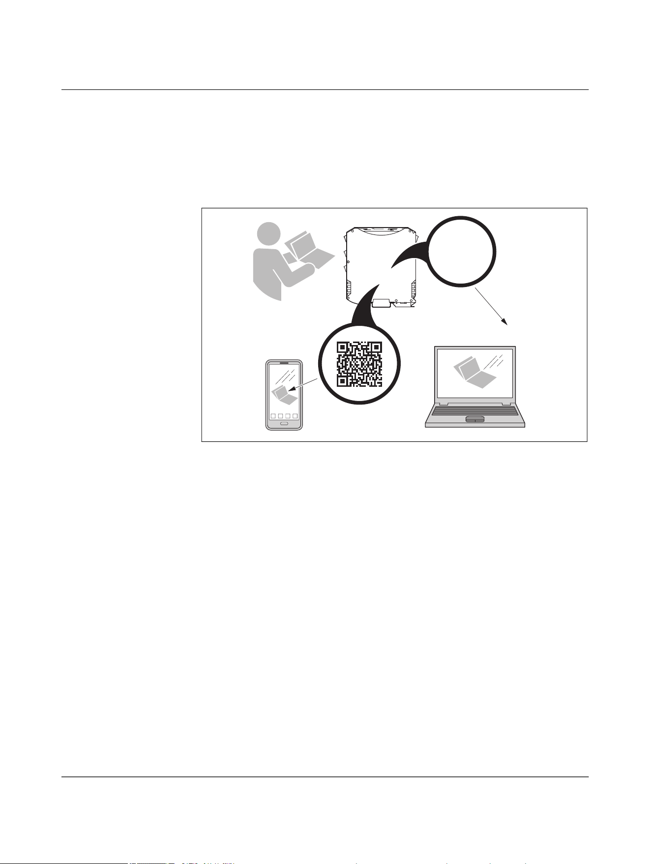
1.6 User documentation
• Read the user documentation prior to installation and startup.
• You can find the full user documentation on the Internet at
“phoenixcontact.com/qr/xxx”. Replace “xxx” with the item number of the product.
• You can also use the QR code on the product.
Figure 1-1 Scanning the QR code
?
phoenixcontact.com/qr/1234567
Item No.
1234567

For your safety
110718_en_02 Phoenix Contact 9 / 102
1.7 UL notes
CAUTION:
The external circuits intended to be connected to this device must be isolated from
the mains or hazardous voltages by reinforced or double insulation and meet the re-
quirements of SELV/PELV circuits (Class III) in accordance with
UL/CSA/IEC 61010-1, 61010-2-201.
To install the device in accordance with the UL/CSA standards, the following rules
must be observed.
– If the equipment is used in a manner not specified, the protection provided by the
equipment may be impaired.
– Minimum ambient temperature rating of the cable assemblies (CYJV2/8, CYJV/7 /
PVVA2/8, PVVA/7) connected to the terminals:
– 65°C, minimum
– AWG 24 ... 16
– 60 V DC, minimum
– 4 A, minimum/8 A, minimum (for power couplers in parallel operation)
– Use copper conductors only.
– Use UL-listed or suitable accessories only:
– M12
– 60 V DC, minimum
– 4 A, minimum/8 A, minimum (for power couplers in parallel operation)
– Ambient temperature 65°C, minimum
NEARFI
10 / 96 Phoenix Contact
110718_en_02
2 FCC approval
2.1 Part15
This device complies with Part 15 of the FCC rules. Operation is subject to the following
two conditions:
(1) This device may not cause harmful interference.
(2) This device must accept any interference received, including interference that may
cause undesired operation.
NOTE: Interference
This equipment has been tested and found to comply with the limits for a Class A
digital device, pursuant to part 15 of the FCC rules. These limits are designed to pro-
vide reasonable protection against harmful interference when the equipment is op-
erated in a commercial environment. This equipment generates, uses and can
radiate radio frequency energy and, if not installed and used in accordance with the
instruction manual, may cause harmful interference to radio communications. Op-
eration of this equipment in a residential area is likely to cause harmful interfer-
ence, in which case, the user will be required to correct the interference at his own
expense.
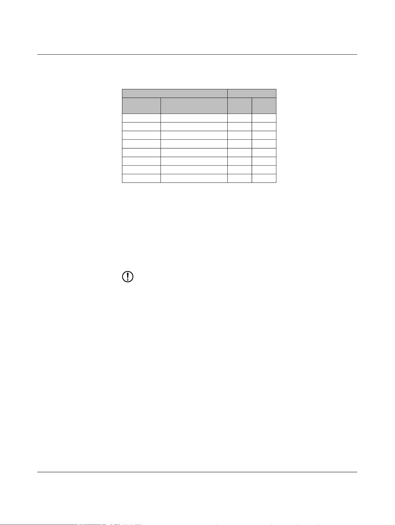
Radio approval for USA, FCC ( = applicable)
NEARFI... Certificate FCC,
part15
FCC,
part18
2200 B YG32200B
2200 R YG32200R
200 B YG3200B
200 R YG3200R
300 B YG3300B
300 R YG3300R
2000 B YG32000B
2000 R YG32000R

FCC approval
110718_en_02 Phoenix Contact 11 / 96
2.2 Part18
This device complies with Part 18 of the FCC rules.
This equipment generates, uses and can radiate radio frequency energy and, if not in-
stalled and used in accordance with the instructions, may cause harmful interference to
radio communications.
If this equipment does cause harmful interference to radio or television reception, which
can be determined by turning the equipment off and on, the user is encouraged to try to
correct the interference by one or more of the following measures:
• Increase the separation between the equipment and any other radio device.
• Connect the equipment into an outlet on a circuit different from that to which the re-
ceiver is connected.
2.3 Intended use description for industrial inductive
couplers
Industrial inductive couplers are designed for the contactless transmission of power via
small air gaps in industrial machines or systems. They are designed to increase system
reliability by eliminating mechanical wear, reducing maintenance and enabling flexible
machine and production concepts. Their use is particularly beneficial in environments
where cables, connectors or slip rings would suffer from mechanical stress, contamina-
tion or frequent disconnection cycles.
Some possible applications are described below:
Robotics and automated tool changing
Inductive couplers are used to supply power and communication to robotic end-effectors
and exchangeable tools. By eliminating plug connections, they support rapid tool
changes, minimize downtime, and ensure reliable transmission even under dynamic
movement and vibration.
Mobile workpiece carriers and conveyor systems
They enable power transfer to mobile transport units or workpiece carriers without me-
chanical connectors. This supports flexible production concepts.
Rotating systems
In rotary tables, rotating grippers, and other continuously rotating equipment, inductive
couplers replace slip rings, offering a maintenance-free solution for uninterrupted power
transfer.
Hygienic and sterile environments
For applications in sterilization systems or hygienic manufacturing areas, inductive cou-
plers provide a sealed, wear-free interface. They avoid contamination risks associated
with mechanical connectors and maintain performance under frequent cleaning cycles.
Machine tools and general industrial automation
Inductive couplers supply sensors, actuators, and interchangeable modules within
presses, assembly stations, and handling systems. They prevent cable fatigue, especially
in harsh mechanical environments.

NEARFI
12 / 96 Phoenix Contact
110718_en_02
Transfer through non-metallic barriers
They support contactless transmission through plastic or composite walls, allowing en-
capsulated installations where direct electrical connections are undesirable or impossi-
ble.
Auxiliary power and galvanically isolated supply systems
Inductive couplers can serve as galvanically isolated auxiliary power sources, supporting
applications that require high isolation or safe power delivery to moving components.
2.4 Installation instructions for applications using
Nearfi base units (NEARFI 2200 B, NEARFI 300 B,
NEARFI 200 B)
2.4.1 Scope of installation
These instructions apply to all installations in which NearFi base units are integrated for
contactless power transmission. All installation, configuration, and maintenance work
must be performed by qualified personnel in accordance with applicable machinery,
EMC, and occupational safety regulations.
2.4.2 Safety requirements
2.4.2.1 Non-accessible area requirement
The installation must always ensure that the NearFi base unit is located in a permanently
non-accessible area. This condition must be achieved and maintained through one or
more of the following protective measures:
– Structural measures:
– Protective cages
– Closed housings
– Electrical measures:
– Interlocked safety gates
– Power cut-off mechanisms preventing operation when the protected area is
open
– Organizational measures:
– Defined safety zones around the operating area
– Marked and controlled access restrictions
– Physical barriers that prevent unintended human entry
These protective measures must always guarantee a minimum distance of 13 cm be-
tween any human body part and the NearFi base unit during normal operation. This min-
imum distance is mandatory according to KDB 951290 and must not be reduced under
any operating conditions.

FCC approval
110718_en_02 Phoenix Contact 13 / 96
2.4.2.2 Access control during operation
Under no circumstances may a person enter or access the protected area while the
NearFi base unit is energized.
Before any human enters this area - including for maintenance, cleaning, inspection, or
troubleshooting - the following conditions must be fulfilled:
– The entire machine, including the NearFi Base unit, must be switched off by a cer-
tified safety mechanism, such as:
– Emergency stop circuit
– Safety-rated power interlock
– Lockout-tagout (LOTO) procedure
– The safety mechanism must reliably interrupt the power supply to the NearFi base
unit.
– The machine must remain de-energized and secured against restart until all work
in the area is completed.
2.4.3 Installation procedure
2.4.3.1 Preparation
• Verify that structural, electrical, or organizational measures fulfilling the non-acces-
sible area requirement are installed and functioning.
• Confirm that the protective design ensures the 13-cm minimum distance at all
times.
• Ensure that the safety mechanism used for power shutdown is approved and tested.
2.4.3.2 Mounting the NearFi base unit
• Mount the unit in the designated protected space according to the mechanical spec-
ifications.
• Ensure that no part of the installation allows accidental human reach within the
13-cm distance zone.
• Route all cables and connectors outside of human-accessible areas.
2.4.3.3 Verification of safety measures
After installation:
• Test the protective enclosure or barrier for stability and correct positioning.
• Test the safety shutdown mechanism to ensure immediate power cut-off.
• Validate that access to the protected area cannot occur without prior de-energiza-
tion.
2.4.3.4 Commissioning
• Restore power only after confirming that all protective measures are in place and ful-
ly functional.
• Verify correct NearFi operation while ensuring no personnel can access the protected
zone.

NEARFI
14 / 96 Phoenix Contact
110718_en_02
2.4.3.5 Maintenance and service
• Any maintenance activity requiring entry into the protected zone must follow the
mandatory shutdown procedure:
– Activate the safety mechanism to remove power from the machine and NearFi
base unit.
– Apply lockout-tagout or equivalent measures.
– Verify zero-energy state before entering.
• Restart the system only after ensuring the zone is cleared and protective barriers are
properly closed.
2.4.4 FCC statement
The FCC certification of this device is based on RF exposure testing performed under typ-
ical operating conditions, where a person remains at least 13 centimeters away from the
device surface at all times, except during non-repetitive patterns with transient durations
on the order of a second. Only under these specified conditions, the device is shown to
fully comply with the FCC RF Exposure requirements of KDB 447498.
2.5 Part 15, 18
Any changes or modifications not explicitly approved by Phoenix Contact could cause the
device to cease to comply with FCC rules Part 15/18, and thus void the user's authority to
operate the equipment.
2.5.1 FCC statement
This equipment should be installed and operated with a minimum distance of 13 cm be-
tween the radiator and your body.

Transport, storage, and unpacking
110718_en_02 Phoenix Contact 15 / 96
3 Transport, storage, and unpacking
3.1 Transport
The device is delivered in cardboard packaging.
• Only transport the device to its destination in its original packaging.
• Observe the instructions on how to handle the package, as well as the moisture,
shock, tilt, and temperature indicators on the packaging.
• Observe the humidity specifications and the temperature range specified for trans-
port (see “Ambient conditions” on page 91).
• Protect the surfaces as necessary to prevent damage.
• When transporting the equipment or storing it temporarily, make sure that the sur-
faces are protected from the elements and any external influences, and that they are
kept dry and clean.
3.2 Storage
The storage location must meet the following requirements:
– Dry
– Protected against unauthorized access
– Protected from harmful environmental influences such as UV light
• For storage/transport, observe the humidity and air pressure specifications, and the
temperature range.
See “Ambient conditions” on page 91.

NEARFI
16 / 96 Phoenix Contact
110718_en_02
3.3 Unpacking
NOTE: Electrostatic discharge
Electrostatic discharge can damage or destroy components.
• When handling the device, observe the necessary safety precautions against
electrostatic discharge (ESD) in accordance with EN 61340-5-1 and IEC 61340-
5-1.
Checking the delivery • Check the delivery for transport damage.
Damaged packaging is an indicator of potential damage to the device that may have oc-
curred during transport. This could result in a malfunction.
• Immediately upon delivery, check the delivery note to ensure that the delivery is
complete.
• Submit claims for any transport damage immediately, and inform Phoenix Contact or
your supplier as well as the shipping company without delay.
• Enclose photos clearly documenting the damage to the packaging and/or delivery to-
gether with your claim.
• Keep the box and packaging material in case you need to return the product.
• We strongly recommend using the original packaging to return the product.
• If the original packaging is no longer available, observe the following points:
– Observe the humidity specifications and the temperature range specified for
transport (see “Ambient conditions” on page 91).
– Use dehumidifying agents if necessary.
– Use suitable ESD packaging to protect components that are sensitive to electro-
static discharge.
– Make sure that the packaging you select is large enough and sufficiently thick.
– Only use plastic bubble wrap sheets as wadding.
– Attach warnings to the transport packaging so that they are clearly visible.
– Please ensure that the delivery note is placed inside the package if the package
is to be shipped domestically. However, if the package is being shipped interna-
tionally, the delivery note must be placed inside a delivery note pocket and at-
tached to the outside so that it is clearly visible.

Product description
110718_en_02 Phoenix Contact 17 / 102
4 Product description
The NearFi couplers transmit power and real-time Ethernet data across an air gap of a few
centimeters:
– 50 W in stand-alone operation or 100 W in parallel operation
– 100 Mbps, full duplex
Transmission is even possible through materials such as wood, glass, and plastic. This al-
lows you to use this technology to replace wear-prone connections and slip rings in in-
dustrial applications, while minimizing costly outages.
The base and remote couplers are both available in four versions:
– Power and data transmission (NEARFI 2200)
– Power transmission only
– Communications power and sensor supply, US (NEARFI 200)
– Actuator supply, UA (NEARFI 300)
– Data transmission only (NEARFI 2000)
Characteristics
– Contactless
Therefore no wear and no maintenance
– Flexible
High degree of mounting freedom with flexible proximity options
– Universal
Protocol-independent and latency-free real-time Ethernet communication with
100 Mbps (full duplex)
– Plug-and-play
Base and remote couplers connect automatically
No configuration
– Visible
All-round easily recognizable diagnostics with LED ring on the housing
– Combination
By combining two NearFi coupler paths, the power can be increased to 100 W with
automatic current equalization, or two electrically isolated voltages (US/UA) of 50 W
each can be transmitted.
NEARFI
18 / 102 Phoenix Contact
110718_en_02
4.1 Functional principle
NearFi couplers transmit power and real-time Ethernet data contactless across an air gap
of just a few centimeters.
For contactless transmission, you will need at least two devices:
– One base coupler
– One or more remote couplers
You can combine as many remote couplers with a base coupler as you like, and vice versa.
Power transmission
The base coupler transmits the power inductively to the remote coupler.
The NearFi couplers transmit 50 W without contact. The base coupler tries to connect to
the remote coupler by means of active power polling. Power transmission between the
base and remote couplers only becomes active once the connection has been estab-
lished.
The 24-V output voltage is kept at an output current of 2 A by an active closed-loop con-
trol circuit until the maximum transmission distance is reached.
Data transmission
Data is transmitted with two 60 GHz connections in parallel (one uplink and one down-
link). Separate frequency bands are used to enable full duplex mode. NearFi enables con-
tactless communication in real time and is completely independent of protocols.
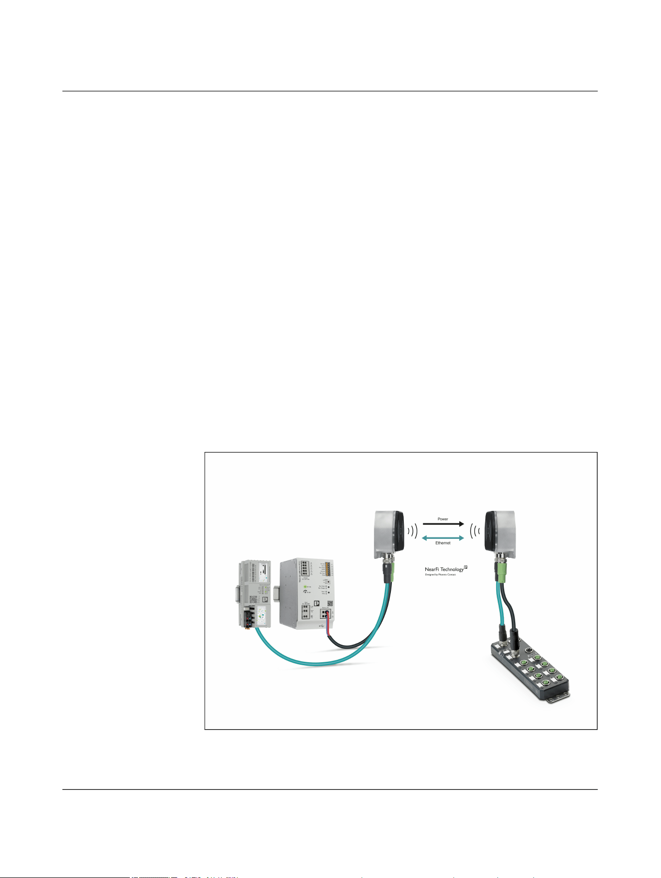
Figure 4-1 Contactless transmission between a controller and a distributed I/O de-
vice with Ethernet interface
Product description
110718_en_02 Phoenix Contact 19 / 102
4.2 Installation examples
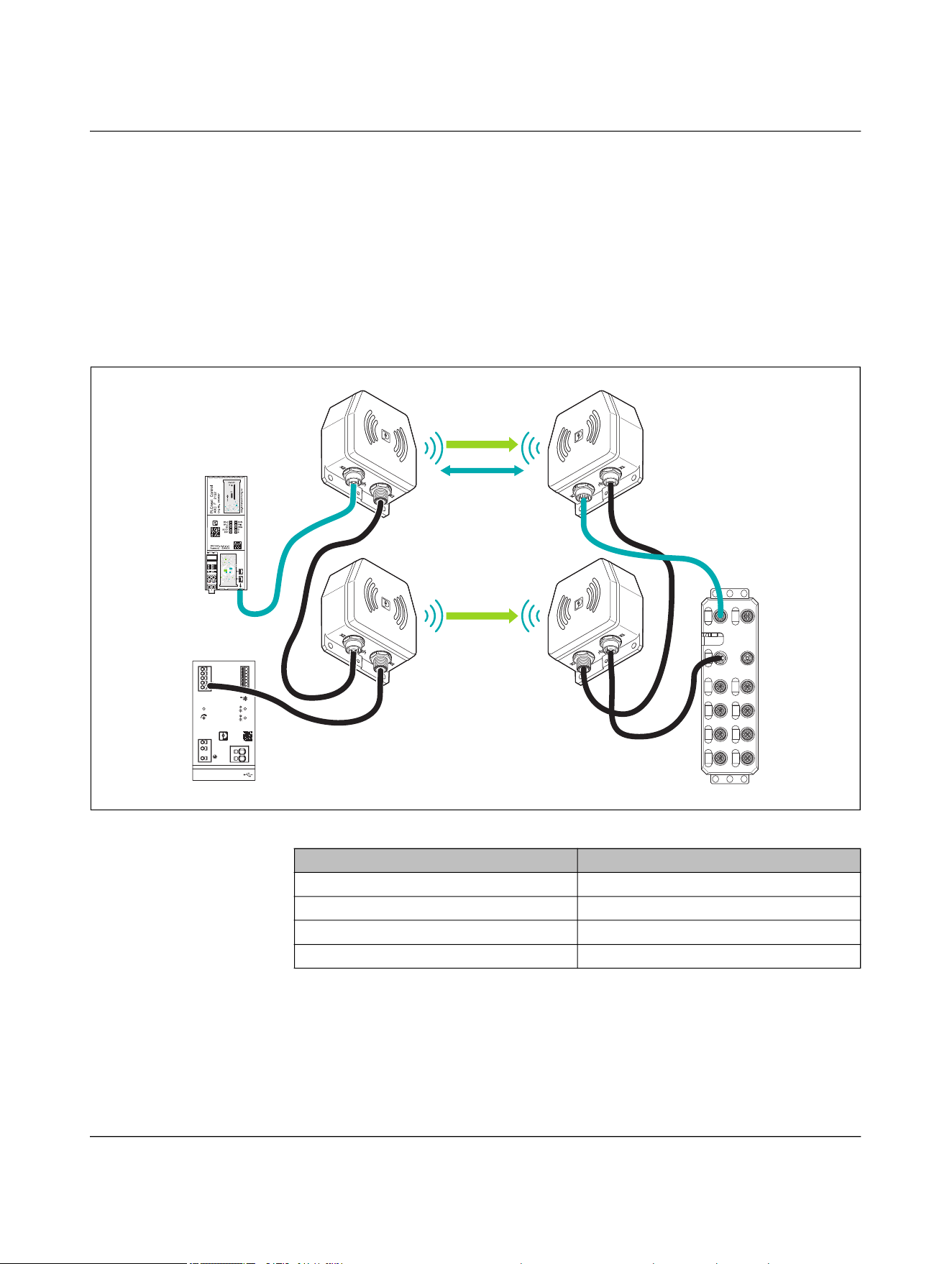
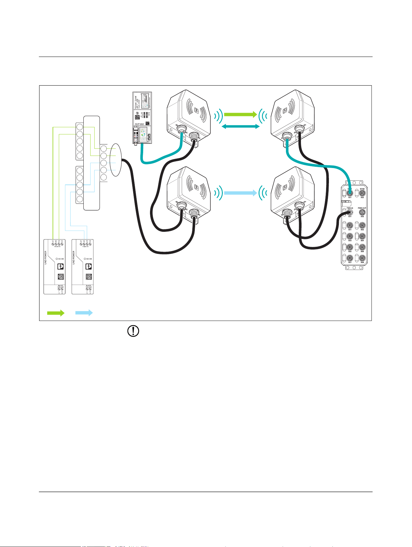
4.2.1 Twice the power using parallel connection
Communications power and sensor supply, 100 W
If you connect two device pairs in parallel, you can double the transmitted power from
50 W to 100 W. With the automatic current equalization, the NEARFI 200 R remote cou-
pler ensures a regulated output voltage of 24 V DC, 4 A.
Figure 4-2 Transmission of data and power (US)
TRIO DC-UPS
Ord. No.2907161
Bat.-Mode
Bat.-Charge
Alarm
P>Pn
DC OK
24-28V
1
2
3
5
15
Service
PC-Mode
Custom
(Default 0.5)
10
t
max
[min]
+
2.1
+
2.2
–
2.3
–
2.4
–
2.5
Output
DC 24V 10A
3.1
3.2
3.3
3.4
3.5
3.6
3.7
DC OK
Alarm
Bat.-Mode
Ready
Remote
Bat.-Start
SGnd
Input
AC 100-240V
L/+
1.1
N/–
1.2
1.3
–
4.2
+
4.1
Battery 24V
ETH1 ETH2
X21 X22
PWR IN PWR OUT
X31 X32
X01 X02
X03 X04
X05 X06
X07 X08
Power (US)
Ethernet
Power (US)
Table 4-1 Devices used in Figure 4-2
Designation Item number
NEARFI 2200 B 1433050
NEARFI 2200 R 1433049
NEARFI 200 B 1433047
NEARFI 200 R 1433046
NEARFI
20 / 102 Phoenix Contact
110718_en_02
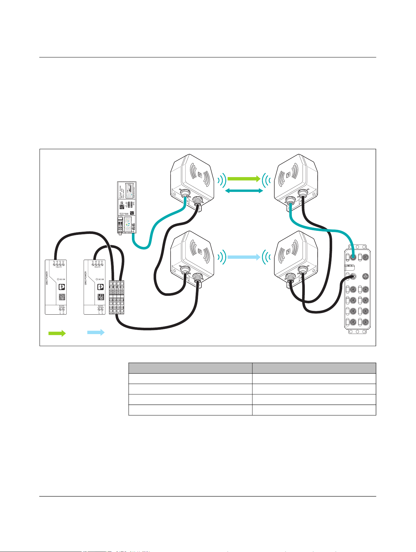
Communications power and sensor supply, 50 W, and actuator supply, 50 W
If you connect the NEARFI 2200 and NEARFI 300 device pairs in parallel, you can trans-
mit two electrically isolated voltages of 50 W each:
– Communications power and sensor supply, US
– Actuator supply, UA
The NearFi couplers are supplied with power and data from the field. Upstream safety de-
vices ensure safe shutdown of the UA voltage.
Figure 4-3 Transmission of data and power (US, UA)
ETH1 ETH2
X21 X22
PWR IN PWR OUT
X31 X32
X01 X02
X03 X04
X05 X06
X07 X08
Power (UA)
Power
(UA)
Power
(US)
Ethernet
Power (US)
Table 4-2 Devices used in Figure 4-3
Designation Item number
NEARFI 2200 B 1433050
NEARFI 2200 R 1433049
NEARFI 300 B 1464614
NEARFI 300 R 1509989
Product description
110718_en_02 Phoenix Contact 21 / 102
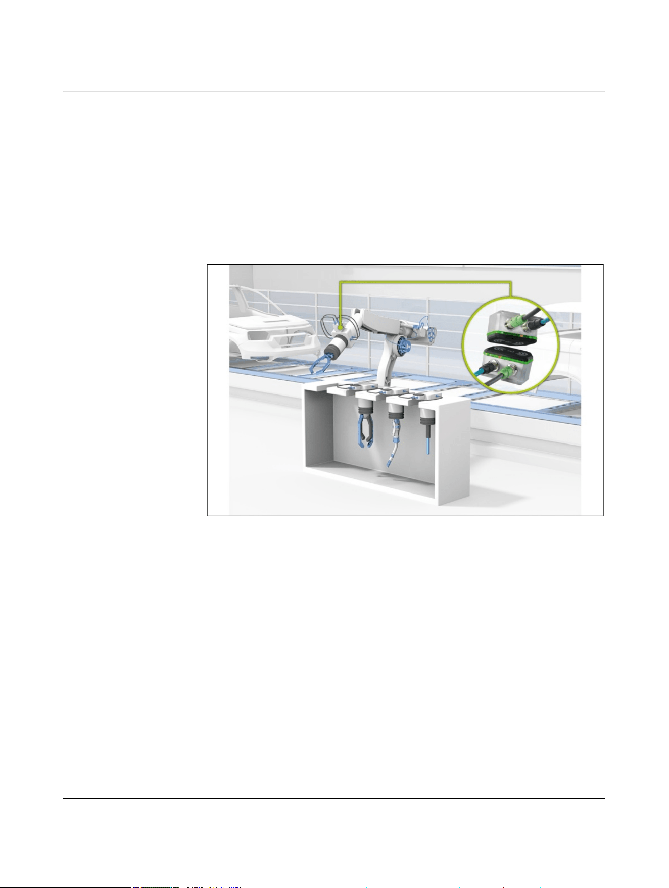
4.2.2 1:n transmission
You can combine as many remote couplers with a base coupler as you like, and vice versa.
Example: tool change
The base coupler is typically mounted on the robot arm. Each tool (number n) gets a
remote coupler. As soon as a remote coupler comes into the vicinity of the base coupler,
the connection is established automatically.
Addressing is not required, as only one remote coupler and one base coupler are facing
each other at a time.
Figure 4-4 Tool change on an industrial robot

NEARFI
22 / 102 Phoenix Contact
110718_en_02
4.2.3 Fields of application
In automation, power and data are mostly transmitted via connectors. Connectors that
have to be frequently unplugged and plugged in again have a limited service life. Their
contacts become misshapen and worn. This leads to unplanned and unforeseeable pro-
duction stoppages and regular maintenance intervals. Contactless real-time communica-
tion systems can provide a solution.
Robot tool change
In maintenance-intensive applications, such as tool changes on robots, you can easily re-
place wear-prone and maintenance-intensive connections with NearFi couplers, thus
minimizing downtime costs.
Material transport systems
Communicate without contact between workpiece carriers and processing stations with
NearFi couplers. Replace slip rings on turntables and rotary tables with wear-free cou-
plers.
Automated guided vehicle systems (AGVS/AGV)
Install NearFi couplers quickly and easily on your automated guided vehicle system
(AGVS) and transmit Ethernet data between charging stations and AGVs without contact.
Rotating applications
Use the NearFi couplers as a replacement for slip rings and transmit Ethernet data in real
time without the need for contact.

Product description
110718_en_02 Phoenix Contact 23 / 102
4.2.4 Operating modes
When it comes to supplying external devices, a distinction is made between two voltages:
– US: Communications power and sensor supply
– UA: Actuator supply
To supply other devices, the NearFi couplers forward the voltages.
Power supply US
The power supply US supplies the communications power of the device electronics as
well as the sensors.
• Connect this supply voltage to each NearFi base coupler. The device will not work if
the voltage is not present.
• Install the power supply for the device electronics independently of the voltage sup-
ply for the actuators.
• Protect the power supplies independently. In this way, the network can continue to
run, even if some I/O devices are switched off.
Power supply UA
The power supply UA supplies the actuators.

NEARFI
24 / 102 Phoenix Contact
110718_en_02
4.2.5 Power and data transmission
Stand-alone operation, Ethernet 100 Mbps, US 50 W
In addition to the real-time Ethernet data, the NEARFI 2200 B base coupler transmits the
voltage (US) to the NEARFI 2200 R remote coupler without contact.
50 W (24 V DC/2 A) are available at output X1 (power OUT) of the remote coupler.
Figure 4-5 Stand-alone operation, Ethernet 100 Mbps, US 50 W
NOTE: Device damage
Never apply voltage to the output X1 (power OUT) of the remote coupler.
Ethernet
Power US
+24 V DC
+24 V DC
Ethernet
NEARFI 2200 B NEARFI 2200 R
Base
Remote
Ethernet
Product description
110718_en_02 Phoenix Contact 25 / 102
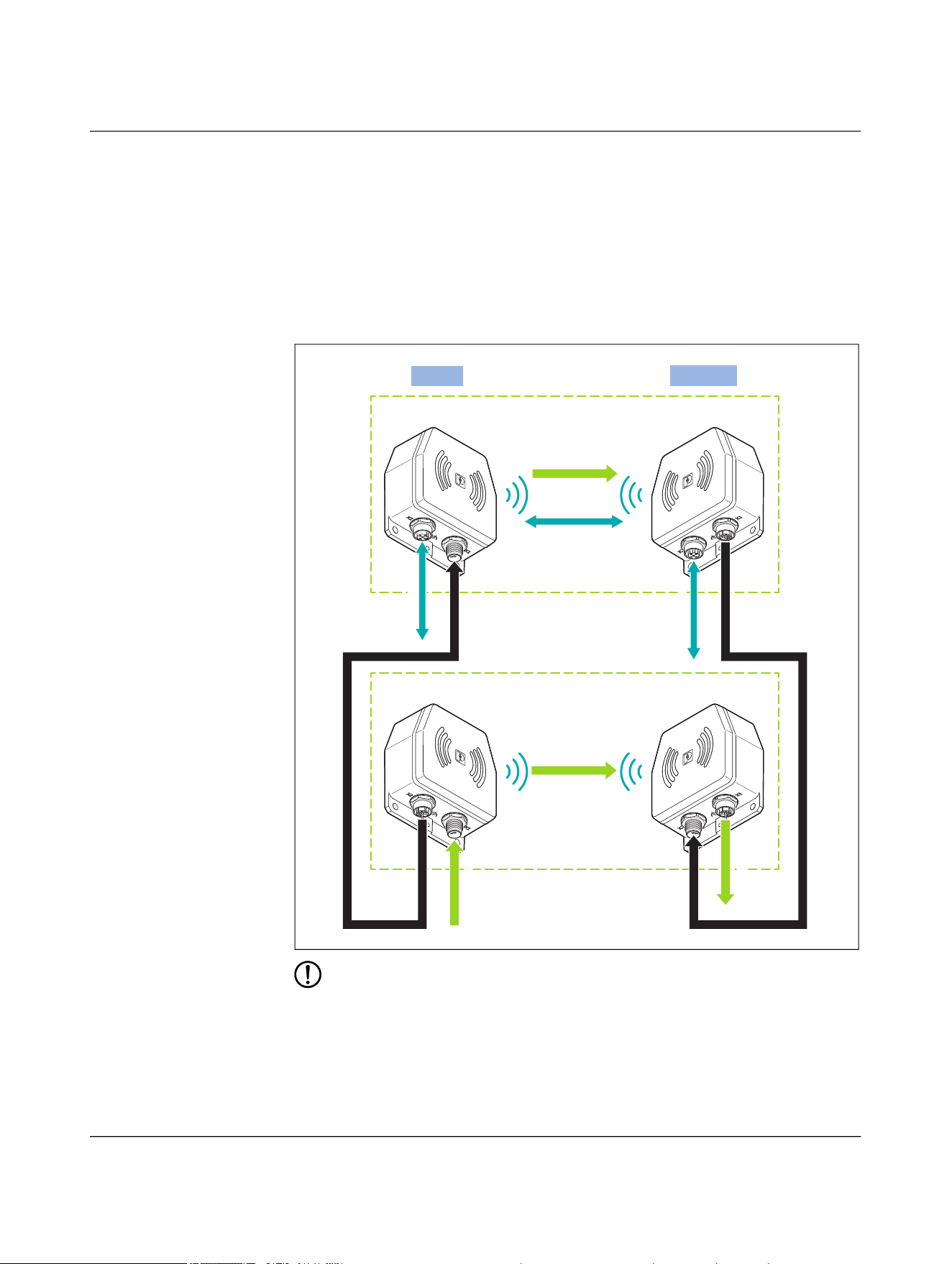
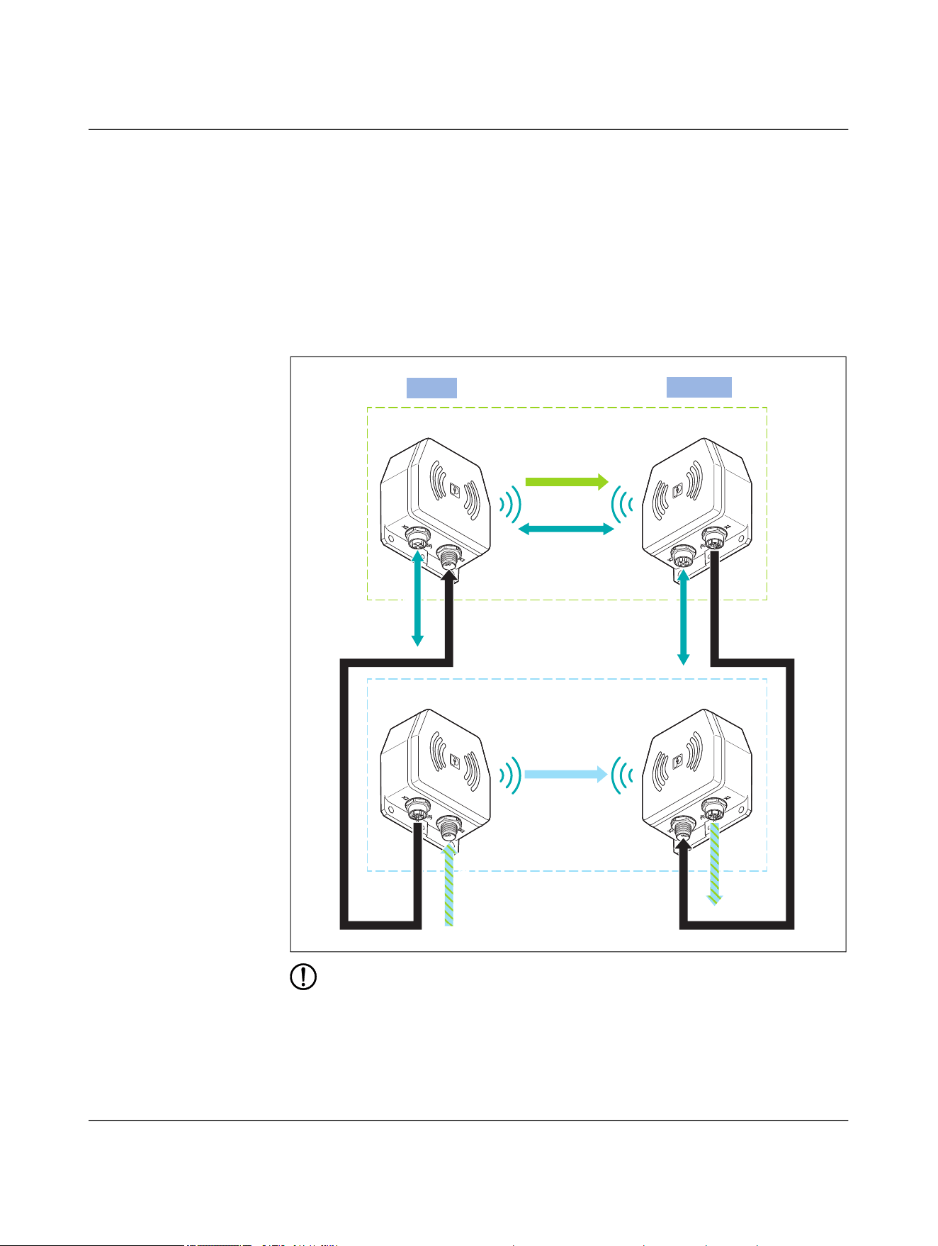
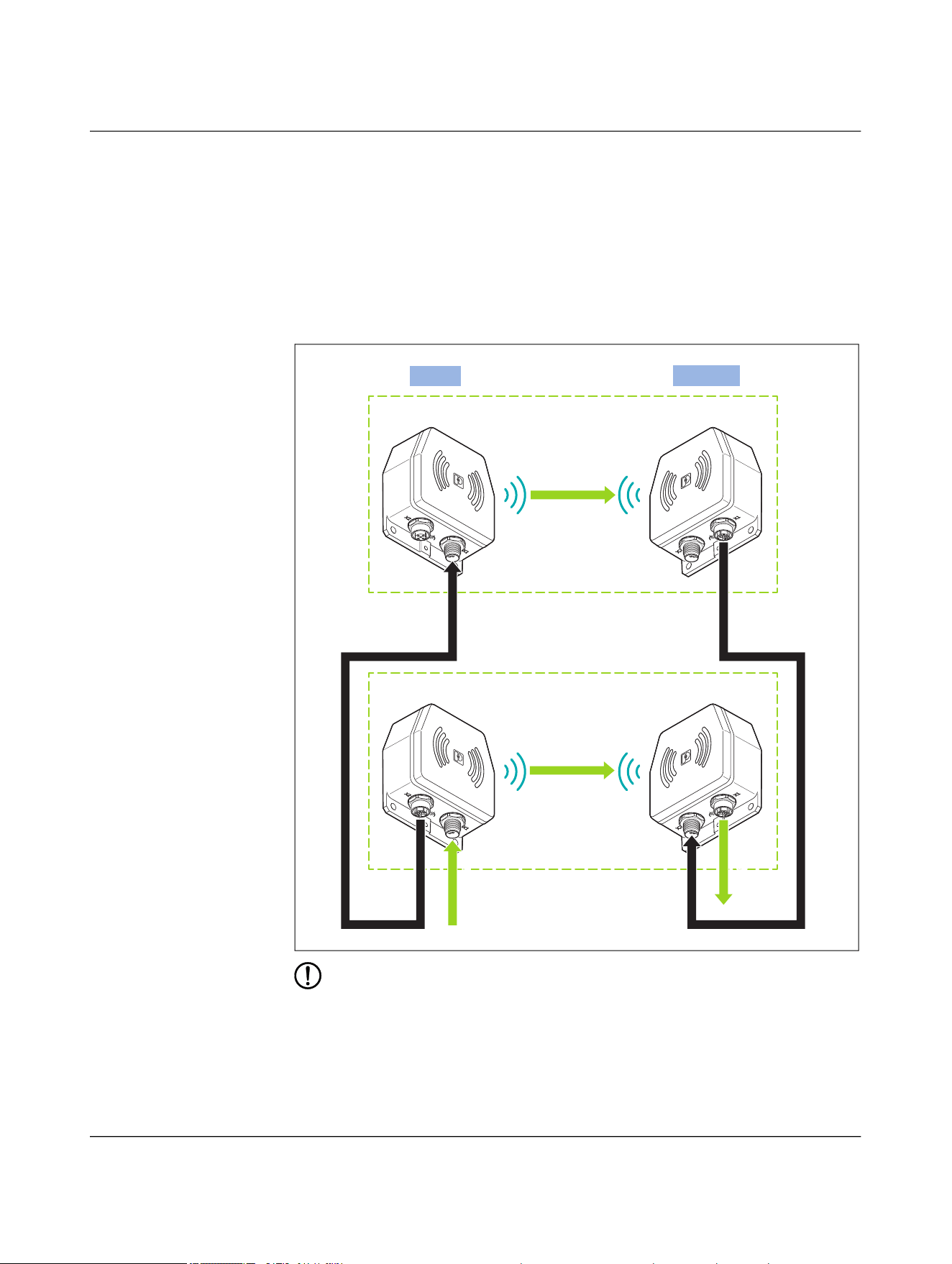
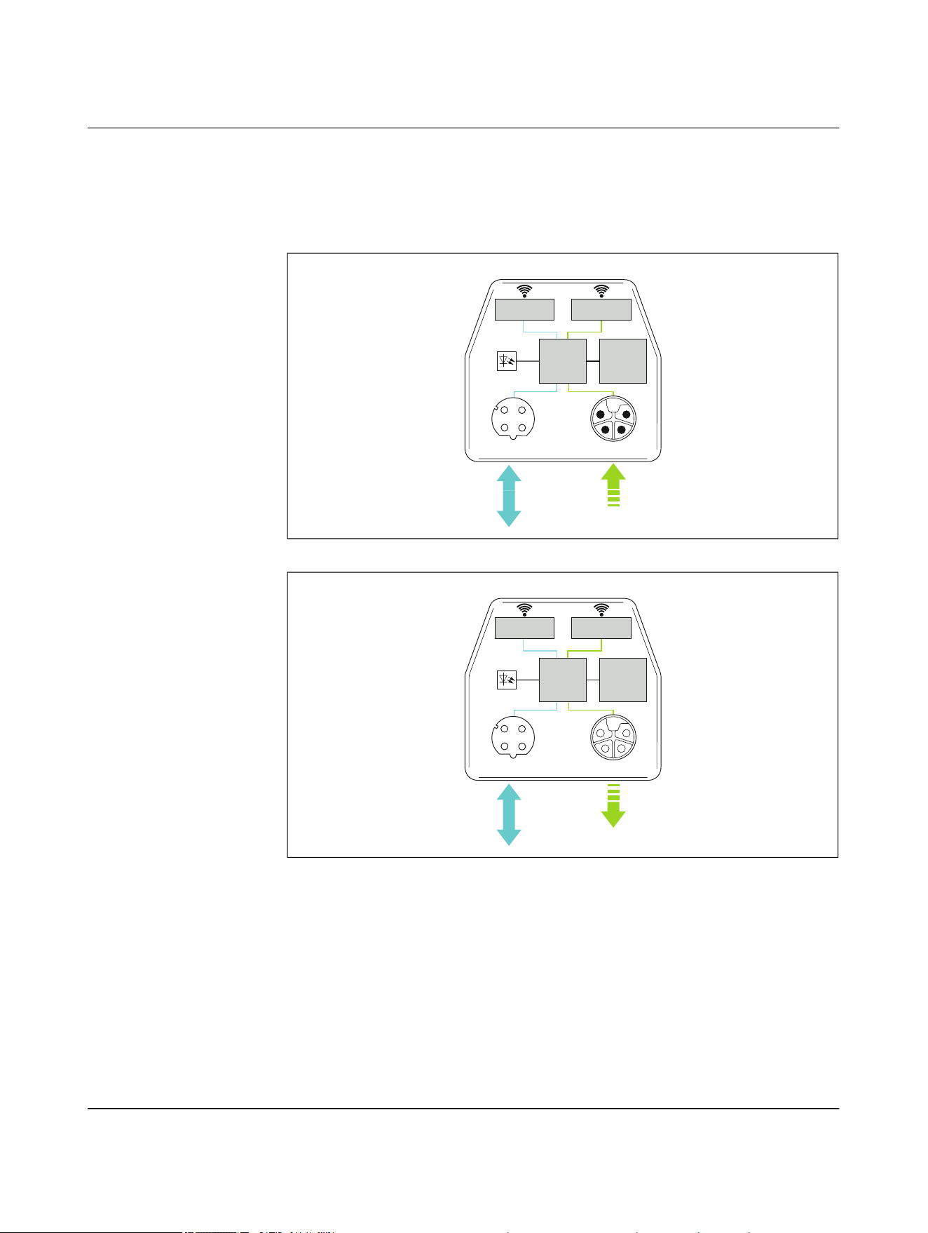
Parallel operation, Ethernet 100 Mbps, US 100 W
– In addition to the real-time Ethernet data, the NEARFI 2200 B base coupler trans-
mits voltage 1 (US) to the NEARFI 2200 R remote coupler without contact.
– The NEARFI 200 B base coupler transmits voltage 2 (US) to the NEARFI 200 R
remote coupler without contact.
– With parallel connection, the following power is available at the NEARFI 200 R
remote coupler, output X1 (power OUT):
– 100 W (24 V DC/4 A)
Figure 4-6 Parallel operation, Ethernet 100 Mbps, US 100 W
NOTE: Device damage
Never apply voltage to the output X1 (power OUT) of the remote coupler.
Ethernet
Power (US)
Ethernet
NEARFI 2200 B NEARFI 2200 R
Base
Remote
Ethernet
Power (US)
NEARFI 200 B NEARFI 200 R
US-2A
US-2A
US/4A
US/4A
NEARFI
26 / 102 Phoenix Contact
110718_en_02
Parallel operation, US 50 W and UA 50 W
– In addition to the real-time Ethernet data, the NEARFI 2200 B base coupler trans-
mits voltage 1 (US) to the NEARFI 2200 R remote coupler without contact.
– The NEARFI 300 B base coupler transmits voltage 2 (UA) to the NEARFI 300 R
remote coupler without contact.
– With parallel connection, two electrically isolated voltages are available at the
NEARFI 300 R remote coupler, output X1 (power OUT):
– Communications voltage US: 50 W (24 V DC/2 A)
– Actuator voltage UA: 50 W (24 V DC/2 A)
Figure 4-7 Parallel operation, US 50 W and UA 50 W
NOTE: Device damage
Never apply voltage to the output X1 (power OUT) of the remote coupler.
Ethernet
Power (US)
Ethernet
NEARFI 2200 B NEARFI 2200 R
Base
Remote
Ethernet
Power (UA)
NEARFI 300 B NEARFI 300 R
US-2A
US-2A
US/UA-2A
US/UA-2A
NEARFI
28 / 102 Phoenix Contact
110718_en_02
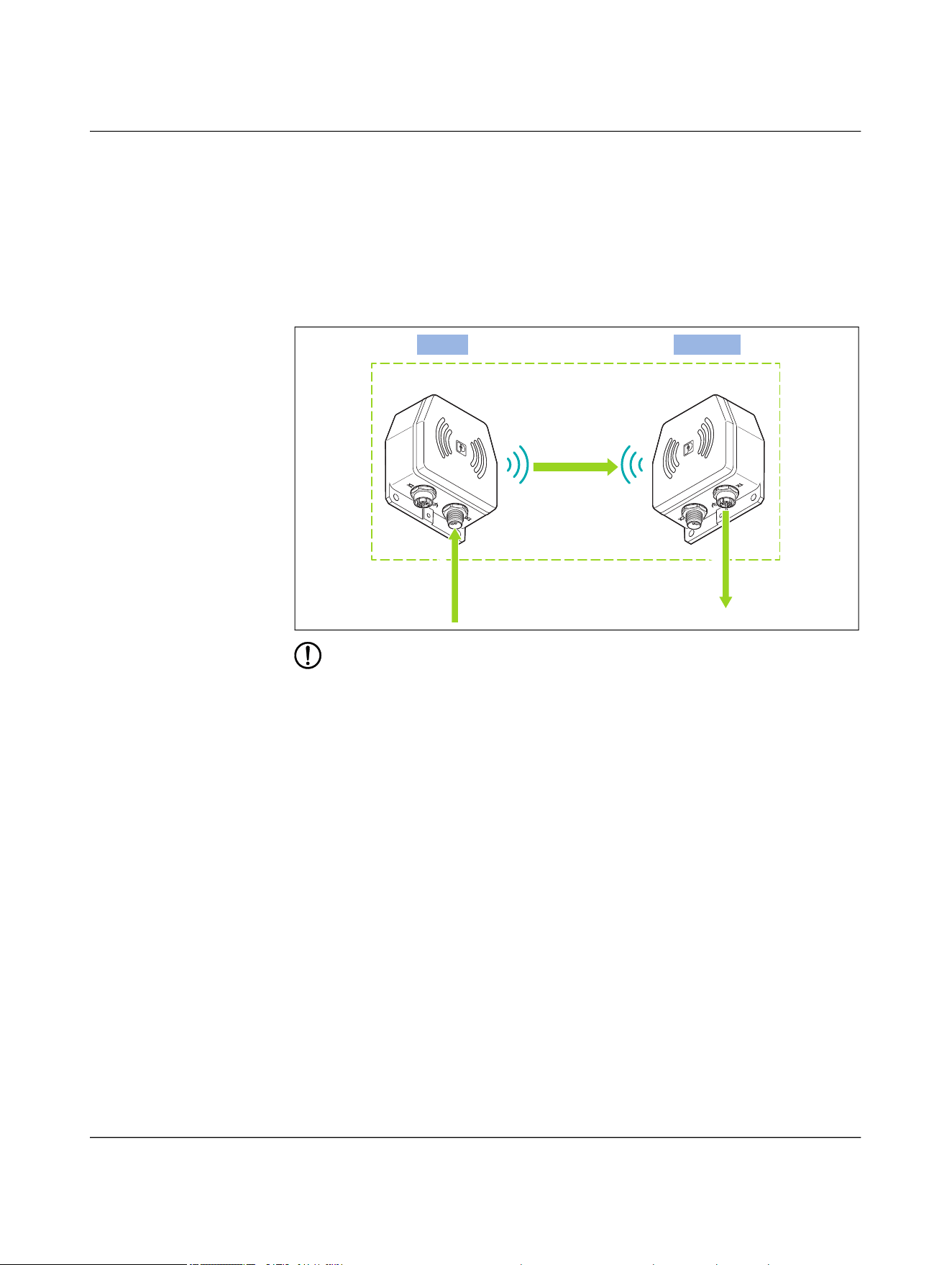
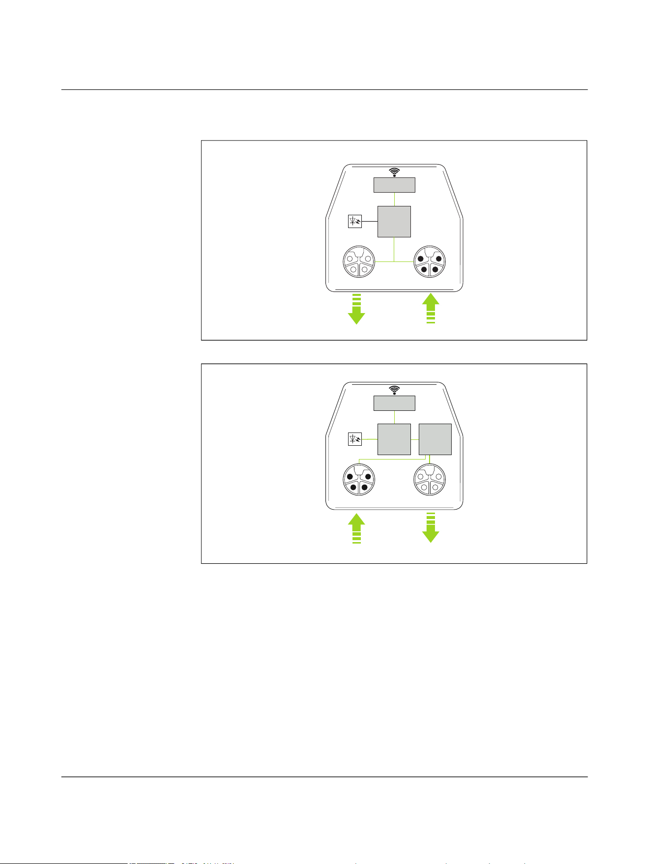
4.2.6 Power transmission
Stand-alone operation, US 50 W
– The NEARFI 200 B base coupler transmits the communications and sensor voltage
(US) to the NEARFI 200 R remote coupler without contact.
– The following power is available at output X1 (power OUT) of the remote coupler:
– 50 W (24 V DC/2 A)
Figure 4-9 Stand-alone operation, US 50 W
NOTE: Device damage
Never apply voltage to the output X1 (power OUT) of the remote coupler.
Base
Remote
NEARFI 200 B NEARFI 200 R
Power (US)
US/2A
US/2A
Product description
110718_en_02 Phoenix Contact 29 / 102
Stand-alone operation, UA 50 W
– The NEARFI 300 B base coupler transmits the actuator voltage (UA) to the
NEARFI 300 R remote coupler without contact.
– The following power is available at output X1 (power OUT) of the remote coupler:
– 50 W (24 V DC/2 A)
Figure 4-10 Stand-alone operation, UA 50 W
NOTE: Device damage
Never apply voltage to the output X1 (power OUT) of the remote coupler.
Base
Remote
NEARFI 300 B NEARFI 300 R
Power (UA)
UA/2A
UA/2A
NEARFI
30 / 102 Phoenix Contact
110718_en_02
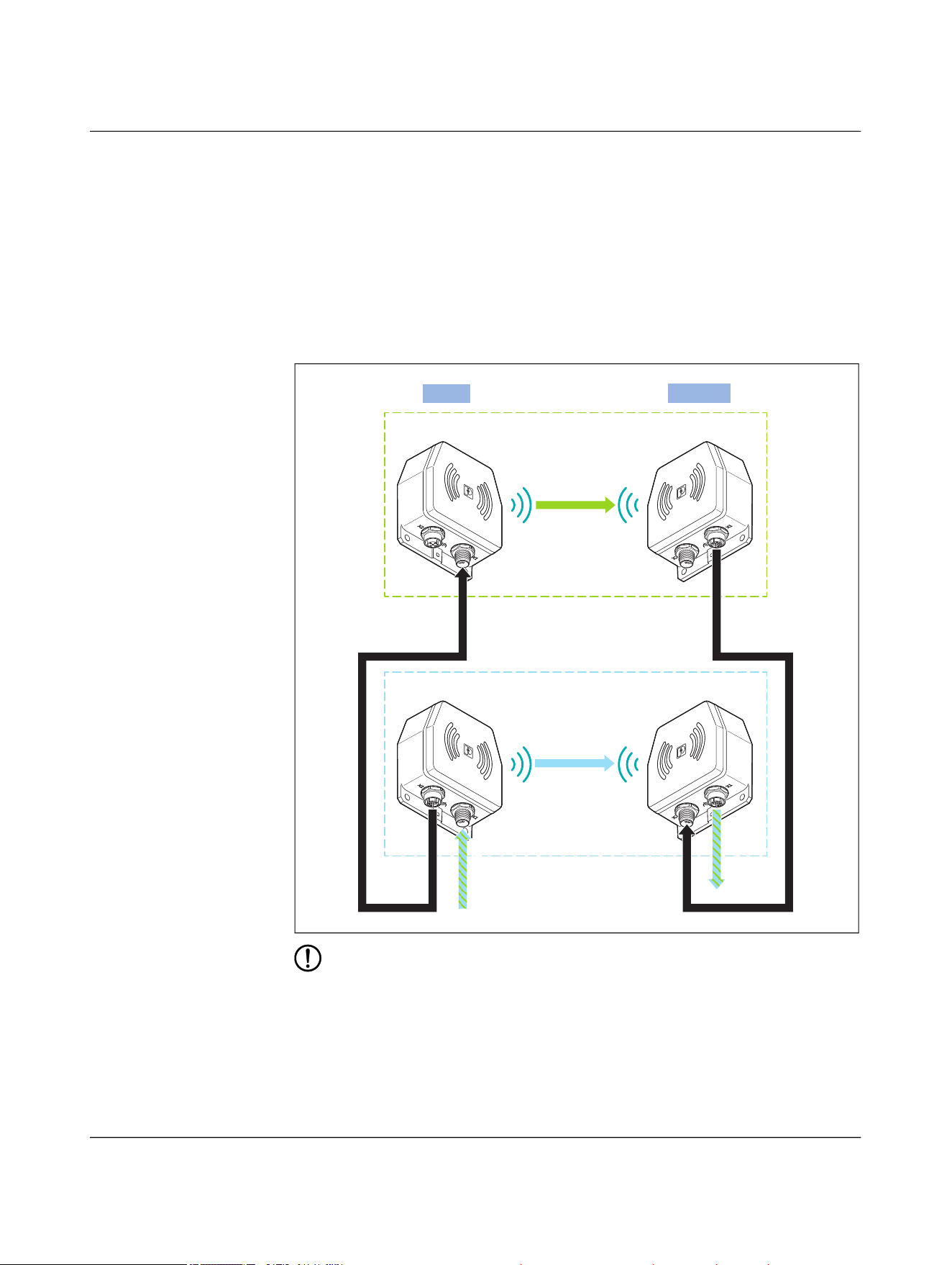
Parallel operation, US 100 W
– The NEARFI 200 B base coupler transmits voltage 1 (US) to the NEARFI 200 R
remote coupler without contact.
– The NEARFI 200 B base coupler transmits voltage 2 (US) to the NEARFI 200 R
remote coupler without contact.
– With parallel connection, the following power is available at the NEARFI 200 R
remote coupler, output X1 (power OUT):
– 100 W (24 V DC/4 A)
Figure 4-11 Parallel operation, US 100 W
NOTE: Device damage
• Never apply voltage to the output X1 (power OUT) of the remote coupler.
• Further cascading of base couplers is not permitted.
Power (US)
NEARFI 200 B NEARFI 200 R
Base
Remote
Power (US)
NEARFI 200 B NEARFI 200 R
US-2A
US-2A
US/4A
US/4A
Product description
110718_en_02 Phoenix Contact 31 / 102
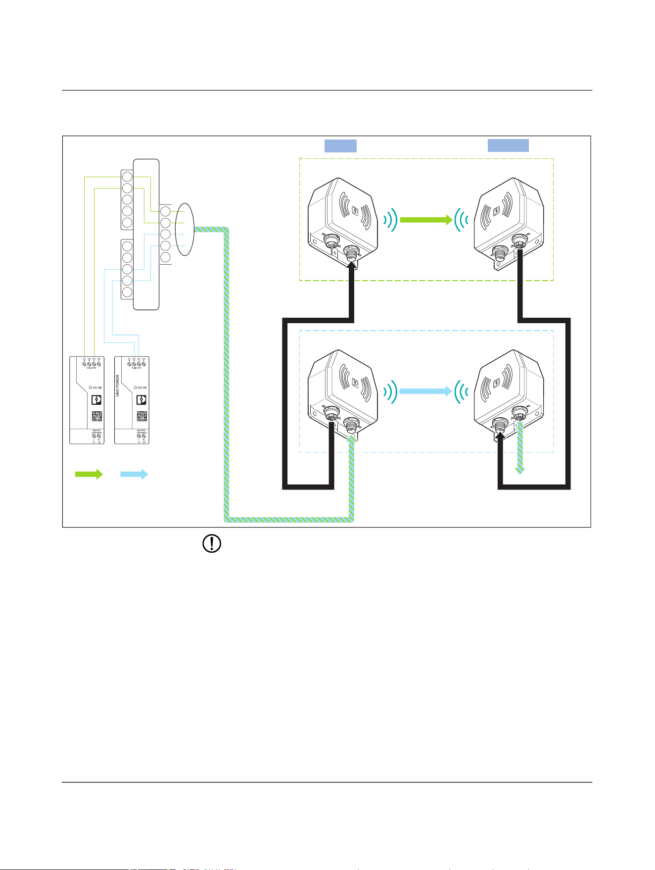
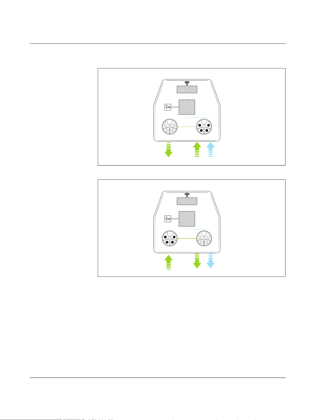
Parallel operation, US 50 W and UA 50 W
– The NEARFI 200 B base coupler transmits voltage 1 (US) to the NEARFI 200 R
remote coupler without contact.
– The NEARFI 300 B base coupler transmits voltage 2 (UA) to the NEARFI 300 R
remote coupler without contact.
– With parallel connection, two electrically isolated voltages are available at the
NEARFI 300 R remote coupler, output X1 (power OUT):
– Communications voltage US: 50 W (24 V DC/2 A)
– Actuator voltage UA: 50 W (24 V DC/2 A)
Figure 4-12 Parallel operation, US 50 W and UA 50 W
NOTE: Device damage
• Never apply voltage to the output X1 (power OUT) of the remote coupler.
• Do not connect a power source (e.g., power supply unit, battery) to the free input
X2 of remote coupler 1.
• You may connect a maximum of one additional remote coupler (X2) to output X1
of remote coupler 1. Further cascading to increase performance is not possible.
Power (US)
NEARFI 200 B NEARFI 200 R
Base
Remote
Power (UA)
NEARFI 300 B NEARFI 300 R
US-2A
US-2A
US/UA-2A
US/UA-2A
NEARFI
32 / 102 Phoenix Contact
110718_en_02
Figure 4-13 Parallel operation, US 50 W and UA 50 W, detailed view with pin assign-
ment
NOTE: Device damage
• Never apply voltage to the output X1 (power OUT) of the remote coupler.
• Do not connect a power source (e.g., power supply unit, battery) to the free input
X2 of remote coupler 1.
• You may connect a maximum of one additional remote coupler (X2) to output X1
of remote coupler 1. Further cascading to increase performance is not possible.
Power (US)
NEARFI 200 B NEARFI 200 R
Base
Remote
Power (UA)
NEARFI 300 B NEARFI 300 R
US-2A
US-2A
US/UA-2A
US/UA-2A
Power
(UA)
Power
(US)
1
3
2
4
F
1
3
2
4
F
1
3
2
4
F
Product description
110718_en_02 Phoenix Contact 33 / 102
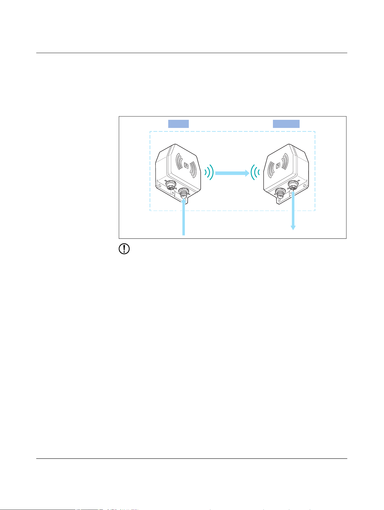
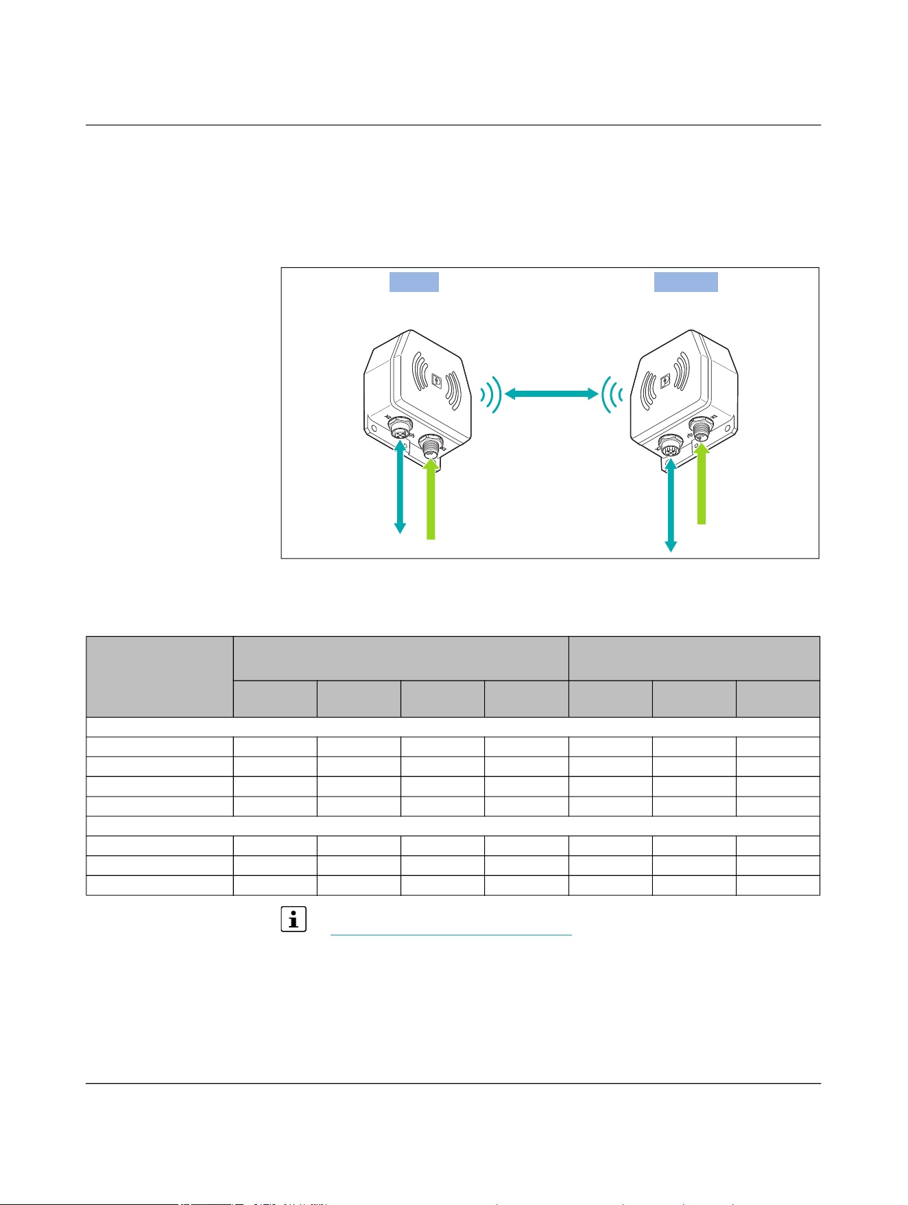
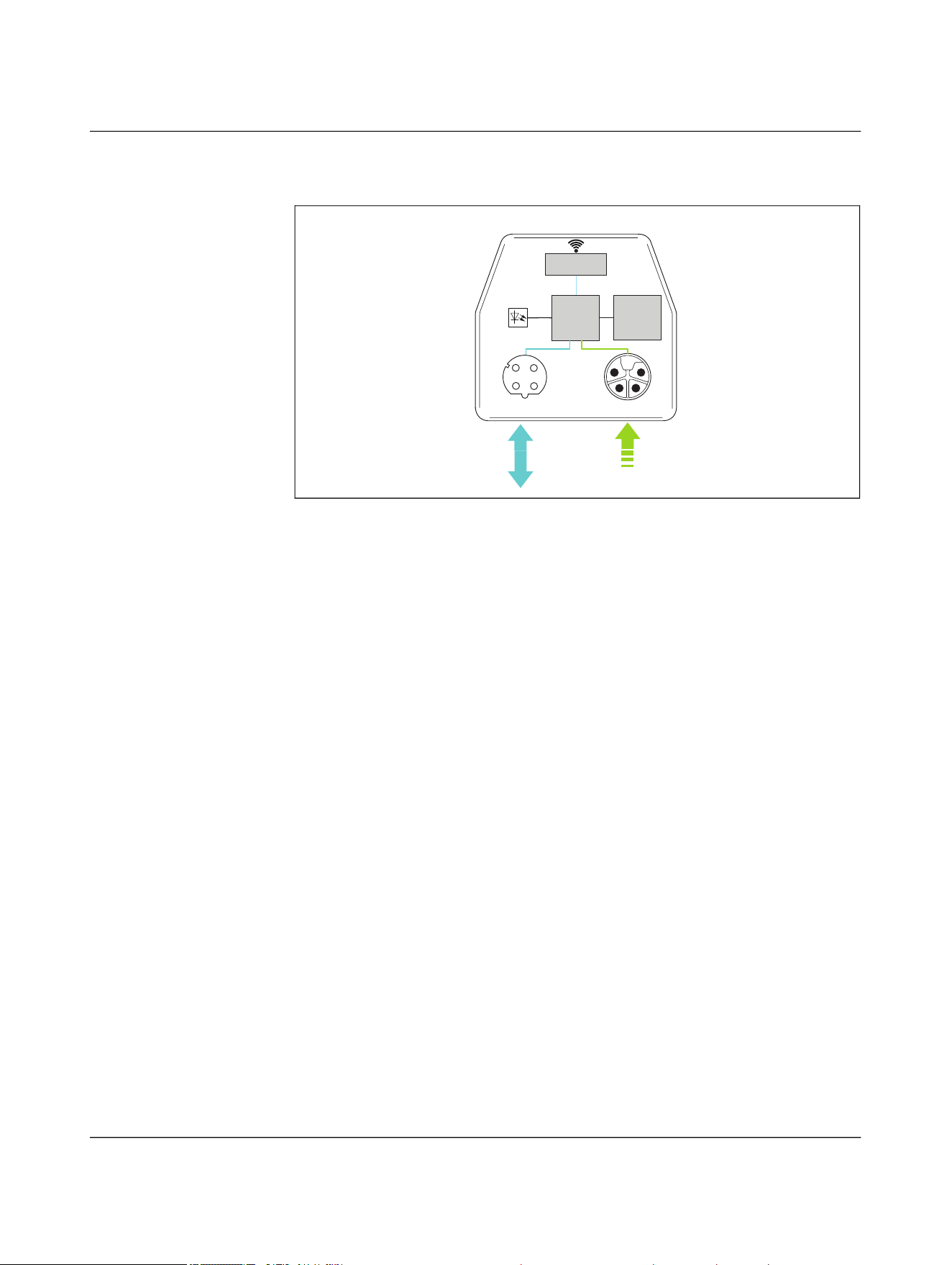
4.2.7 Data transmission
The NEARFI 200 data couplers transmit real-time Ethernet data at 100 Mbps between
the base and remote coupler without contact.
Supply base and remote couplers with 24 V DC each.
Figure 4-14 Data transmission
4.3 Compatibility
The A-coded versions are not described in this manual. You will find the data sheet
at phoenixcontact.com/product/1234225
.
The A-coded and L-coded versions are not compatible with each other.
Ethernet
+24 V DC
+24 V DC
Ethernet
NEARFI 2000 B NEARFI 2000 R
Base
Remote
Ethernet
= Yes, compatible
= No, not compati-
ble
L-coded
NEARFI...
A-coded
NEARFI...
2200 R 200 R 300 R 2000 R PD 2A ETH
R
P 2A R D ETH R
L-coded: NEARFI...
2200 B
200 B
300 B
2000 B
A-coded: NEARFI...
PD 2A ETH B
P 2A B
D ETH B
NEARFI
34 / 102 Phoenix Contact
110718_en_02
4.4 Basic circuit diagram
4.4.1 Power and data coupler (NEARFI 2200)
Figure 4-15 Basic circuit diagram of power and data coupler, base
Figure 4-16 Basic circuit diagram of power and data coupler, remote
Data transmission
(full duplex)
Power Transmitter
(US)
ĎC
ETH-IN/OUT Power-IN
(US)
X1
USETH
X2
LEDs
NEARFI 2200 B
Mode
DIP
ĎC
Data transmission
(full duplex)
Power Receiver
(US)
ETH-IN/OUT Power-OUT
(US)
X1
USETH
X2
LEDs
NEARFI 2200 R
Mode
DIP
Product description
110718_en_02 Phoenix Contact 35 / 102
4.4.2 Power coupler US (NEARFI 200)
Figure 4-17 Basic circuit diagram of power coupler US, base
Figure 4-18 Basic circuit diagram of power coupler US, remote
ĎC
Power Transmitter
(US)
Power-OUT
(US)
Power-IN
(US)
X1X2
US
NEARFI 200 B
ĎC
Power Receiver
(US)
Load
Balancer
(US)
Power-IN
(US)
Power-OUT
(US)
X1X2
LEDs
US
NEARFI 200 R
NEARFI
36 / 102 Phoenix Contact
110718_en_02
4.4.3 Power coupler UA (NEARFI 300)
Figure 4-19 Basic circuit diagram of power coupler UA, base
Figure 4-20 Basic circuit diagram of power coupler UA, remote
ĎC
Power Transmitter
(UA)
Power-OUT
(US)
Power-IN
(US/UA)
UA
X1X2
LEDs
US
NEARFI 300 B
ĎC
Power Receiver
(UA)
Power-IN
(US)
Power-OUT
(US/UA)
UA
X1X2
US
NEARFI 300 R
NEARFI
38 / 102 Phoenix Contact
110718_en_02
4.5 Function elements
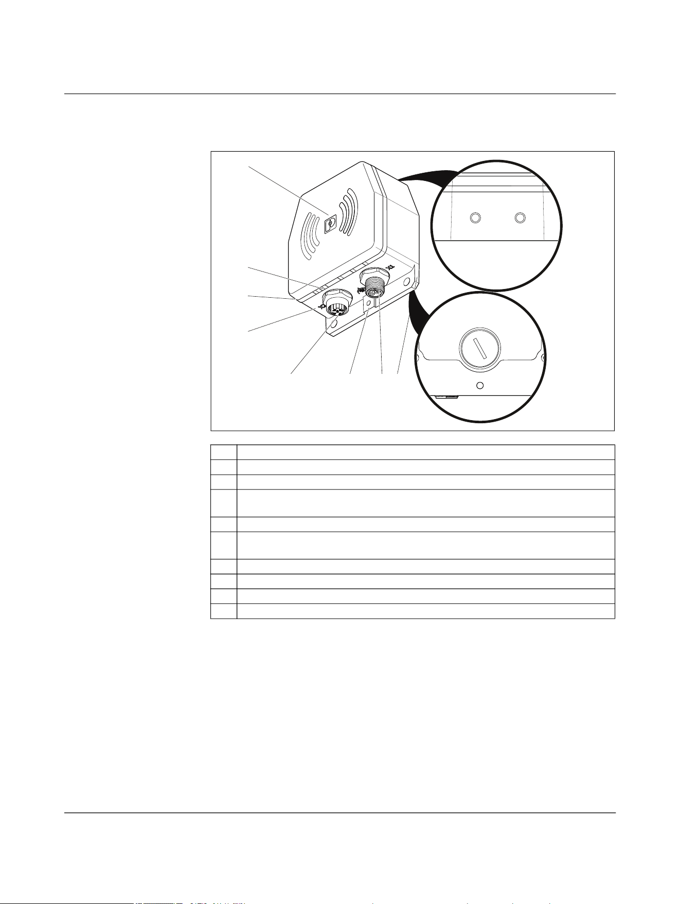
Figure 4-22 Function elements
1 Die-cast housing
2 LED ring (green/yellow/red) for device status diagnostics
3 ETH LINK LED (yellow) for Ethernet diagnostics
4 Upper housing part, power coil and antennas centered in the middle behind the
logo
5 Mounting option with female thread (2 x M6, depth = 7 mm)
6 Bottom of the housing: DIP switches, QR code, additional mounting options with
female thread (4 x M6, depth = 7 mm)
7 Mounting flange with mounting holes (Ø = 5.5 mm)
8 M12 circular connectors for input or output voltage
9 Functional ground connection with female thread (1 x M4, depth = 5 mm)
10 M12 circular connectors for Ethernet
4
3
2
1
10 9 8 7
6
5
Product description
110718_en_02 Phoenix Contact 39 / 102
4.5.1 ETH LINK
4.5.2 LED ring
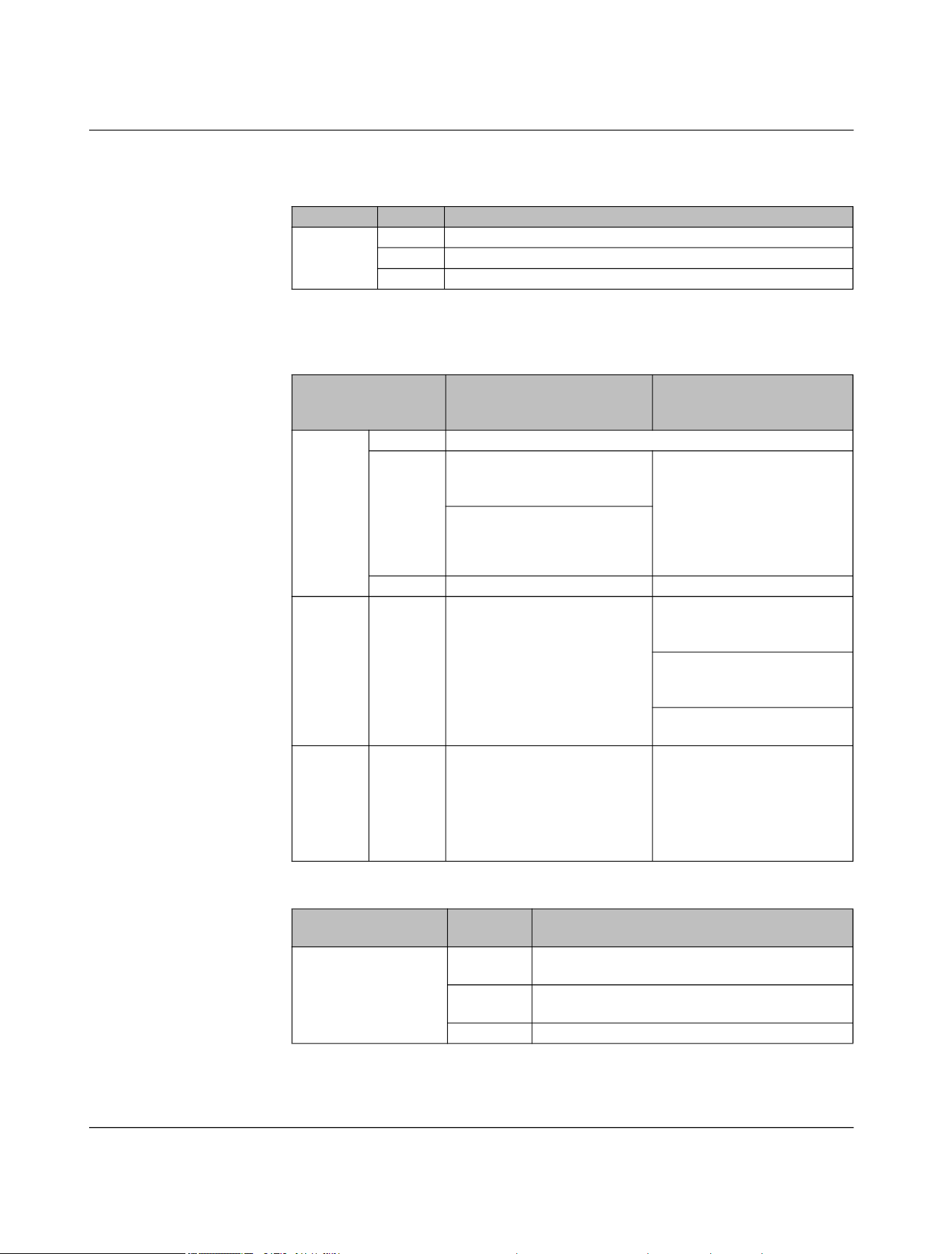
Table 4-3 LED description: ETH Link
ETH LINK Status Description
Yellow On Ethernet link present
Flashing Ethernet data being transmitted
Off No Ethernet link
Table 4-4 LED ring for power and data coupler and power coupler
LED ring
NEARFI 2200 and
NEARFI 200/300
Base Remote
Green On Base and remote coupled, transmission active
Flashing Device ready for operation, no
transmission, air gap or offset
too large
NEARFI 2200 R only:
Remote is supplied with
power from base, device is
ready to operate, no data
transmission, air gap or offset
too large, no Ethernet link (if
LFPT is activated)
Remote voltage output over-
load/short circuit
Off Base not ready for operation Remote not coupled
Yellow Flashing - For parallel connection of two
NearFi paths (NEARFI 200 R
only):
Unfavorable load distribution,
distance between base and
remote coupler too large
One of the two paths is not
working properly
Red On Critical error, internal tempera-
ture too high, external supply
voltage significantly beyond
the nominal range
NEARFI 200 R only:
For parallel connection of two
paths: Critical error, internal
temperature too high,
NEARFI 200 B does not trans-
mit power to NEARFI 200 R
Table 4-5 LED ring for data coupler
LED ring
NEARFI 2000
Status Base and remote
Green On Base and remote coupled, data transmission ac-
tive
Flashing Device ready for operation, no transmission, air
gap or offset too large, devices not coupled
Off Not ready for operation
NEARFI
40 / 102 Phoenix Contact
110718_en_02
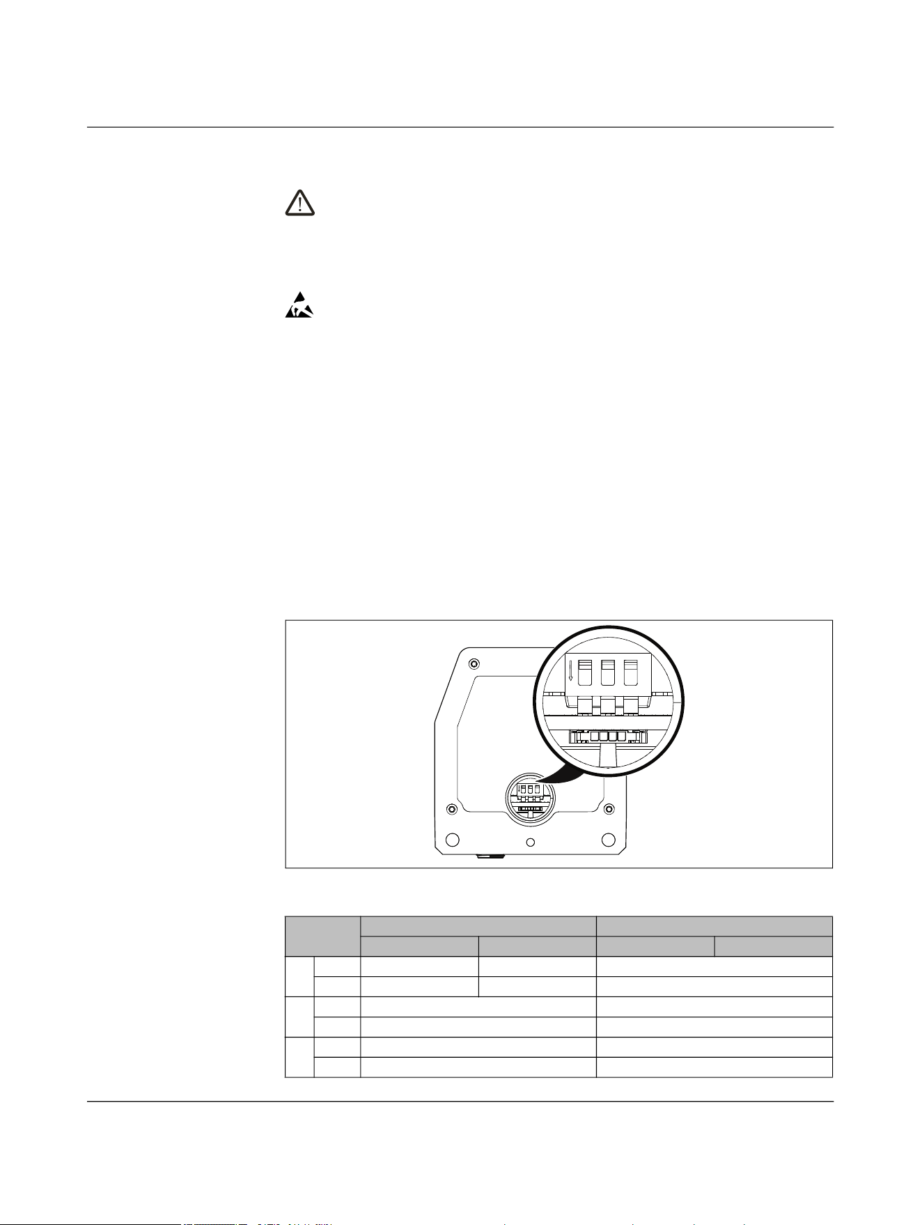
4.6 DIP switches
CAUTION: Electrical voltage
Make sure that the device is disconnected from the power supply before opening
the screw plug.
• Select the operating mode only when the power is disconnected.
• The change is activated after renewed power up.
NOTE: Electrostatic discharge
Electrostatic discharge can damage or destroy components.
• When handling the device, observe the necessary safety precautions against
electrostatic discharge (ESD) in accordance with EN 61340-5-1 and IEC 61340-
5-1.
– In the delivery state, all DIP switches are in the “OFF” position.
– For NEARFI 200/300, the DIP switches have no function.
• Ensure that the device is disconnected from the power supply.
• Ensure that the surroundings are clean so that foreign objects cannot penetrate into
the device.
• Open the M16 screw plug using a bladed screwdriver.
• Set the operating mode using the DIP switches (see Table 4-6).
• Tighten the screw plug to 1 Nm using a bladed screwdriver.
Figure 4-23 DIP switch
Table 4-6 DIP switch
DIP NEARFI 2200 NEARFI 2000
Base Remote Base Remote
1 ON n.c. n.c. Range 40 mm ... 100 mm
OFF n.c. n.c. Range 0 mm ... 40 mm
2 ON ETH full duplex ETH full duplex
OFF ETH auto neg ETH auto neg
3 ON LFPT active (global) LFPT active (global)
OFF LFPT inactive (local) LFPT inactive (local)
ON
123
ON
123

Product description
110718_en_02 Phoenix Contact 41 / 102
4.6.1 DIP 1, range
DIP switch 1 can be used to set two transmission ranges with different ranges. The range
option is only available for NEARFI 2000.
40 mm ... 100 mm (DIP 1 = ON)
If you activate DIP 1, you can achieve a greater range and greater offset for data trans-
mission. Please note that the LFPT function is no longer supported.
0 mm ... 40 mm (DIP 1 = OFF)
Default setting, LFPT is supported
4.6.2 DIP 2, ETH
ETH full duplex (DIP 2 = ON)
Fixed configuration of Ethernet interface X2:
– 100 Mbps, full duplex
– No auto negotiation
– No auto crossing
– MDI-X
The RX and TX cables in the Ethernet port are inverted. You can use standard patch
cables with 1-to-1 connection or straight connection.
– Fast startup (FSU)
This function enables fast startup of the external PROFINET device. The device is
ready for operation in less than 500 ms. Note that the “Fast startup/prioritized
startup” function must be activated on all Ethernet devices in the network.
Disabling crossover detection changes the pin assignment of the network connec-
tion to “Crossover” on the remote coupler.
• Select the connecting cable according to the connected device:
– Crossover cable with same port assignment
– Patch cable with different port assignment
ETH auto neg (DIP 2 = OFF)
Settings for Ethernet interface X2:
– Auto negotiation, 100 Mbps, half or full duplex
– Auto crossing (RX/TX crossover)

NEARFI
42 / 102 Phoenix Contact
110718_en_02
4.6.3 DIP 3, LFPT
The LFPT function is only available for NEARFI 2200 and NEARFI 2000.
Activate LFPT via DIP switch 3. This allows faults to propagate globally through the sys-
tem, or stay local to each link segment.
LFPT, global (DIP 3 = ON)
In the event of a link loss between the base and remote coupler, the couplers shut down
the copper ports. Connection to the connected Ethernet devices is therefore also inter-
rupted. The connection error is forwarded by the port shutdown.
– LFPT provides information on the status of the entire connection.
– EtherCAT® loopback applications are supported.
Please note that LFPT increases the switch-on time. If you require the “Fast start-
up/prioritized startup” function, you need to disable LFPT.
No LFPT, local (DIP 3 = OFF)
The devices may not detect an interruption in the wireless connection. Either the con-
nected device does not know that communication is interrupted. Diagnostics are not pos-
sible. Or the device is constantly trying to restore the connection. This increases the net-
work load and the application response time.

Product description
110718_en_02 Phoenix Contact 43 / 102
4.7 Ethernet
Physical interfaces usually provide an auto negotiation function. As soon as the physical
connection is established between two Ethernet physical layers, the communication pa-
rameters are automatically negotiated. Negotiation can take several seconds.
On the whole, auto negotiation is practical for Ethernet communication. If auto negotia-
tion is active, the fast startup function of industrial protocols, such as PROFINET FSU, is
not supported.
Fast startup
If you require the “Fast startup/prioritized startup” function, you need to disable auto ne-
gotiation on the NearFi couplers. Then use a fixed configuration.
• If required, disable auto negotiation. Set DIP 2 to ON, see page 40.
Link fault pass through (LFPT)
LFPT is required in some applications, e.g., EtherCAT® with loopback function. If the wire-
less connection between the base and remote coupler is lost, the Ethernet port on the
base side is switched off.
• If necessary, enable LFPT. Set DIP 3 to ON, see page 40.

NEARFI
44 / 102 Phoenix Contact
110718_en_02
4.8 Switch-on time (operational readiness time)
Connection establishment between the base and remote is dependent on many different
parameters, such as:
– Approach speed
– Approach angle
– Connected end devices
Data transmission (NEARFI 2200 and NEARFI 2000)
The interface parameters stored on the Ethernet end device also influence the switch-on
time. Auto negotiation and LFPT, for example, delay connection establishment.
General conditions for measurement:
– Fixed setting of 100 Mbps, full duplex, fast startup (DIP 2 = ON)
– LFPT disabled (DIP 3 = OFF)
– PROFINET controller in combination with a PROFINET device
– Spacing of 5 mm, without offset
– Start point of measurement: 24 V is output at the remote coupler
– End point of measurement: Ethernet data is output at the remote coupler
Result:
↪ Maximum switch-on time: < 450 ms
Power coupler (NEARFI 200)
General conditions for measurement:
– Load: 1 A
– Spacing of 5 mm, without offset
– Start point of measurement: Power up of the base coupler
– End point of measurement: 24 V is output at the remote coupler
Result:
↪ Maximum switch-on time: < 80 ms
Power coupler (NEARFI 300)
General conditions for measurement:
– Load: 1 A
– Spacing of 5 mm, without offset
– Start point of measurement: Power up of the base coupler
– End point of measurement: 24 V is output at the remote coupler
Result:
↪ Maximum switch-on time: < 50 ms
NEARFI
46 / 102 Phoenix Contact
110718_en_02
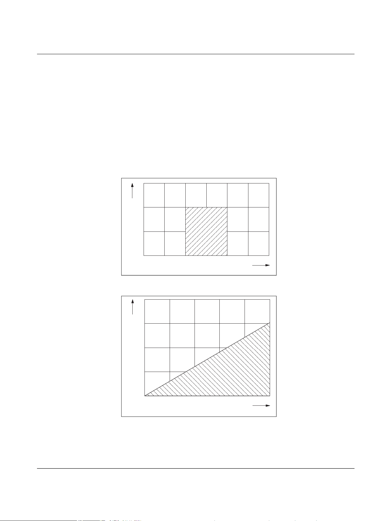
The following diagrams show typical operating ranges with the permissible offset.
– The specified operating range applies in the case of optimal thermal connection.
– Optimum operating range for all versions:
– Transmission distance: 5 mm
– Lateral offset: 0 mm
– Angular offset: 0°
– The specifications for offset apply if the cables of the base and remote coupler exit in
the same direction, see 4.9 “Positioning of the devices”.
– If the cables exit in different directions, the operating range is limited, similar to that
of rotating applications. In this case, the maximum permissible lateral offset is
±2.5 mm.
NEARFI 2200
Figure 4-27 Transmission distance for lateral offset, NEARFI 2200
Figure 4-28 Transmission distance for angular offset, NEARFI 2200
-5-10-15
0
0
15
10
5
15105
Transmission distance [mm]
Lateral offset [mm]
0
Angular offset [°]
Transmission distance [mm]
15
10
5
1086420
20
Product description
110718_en_02 Phoenix Contact 47 / 102
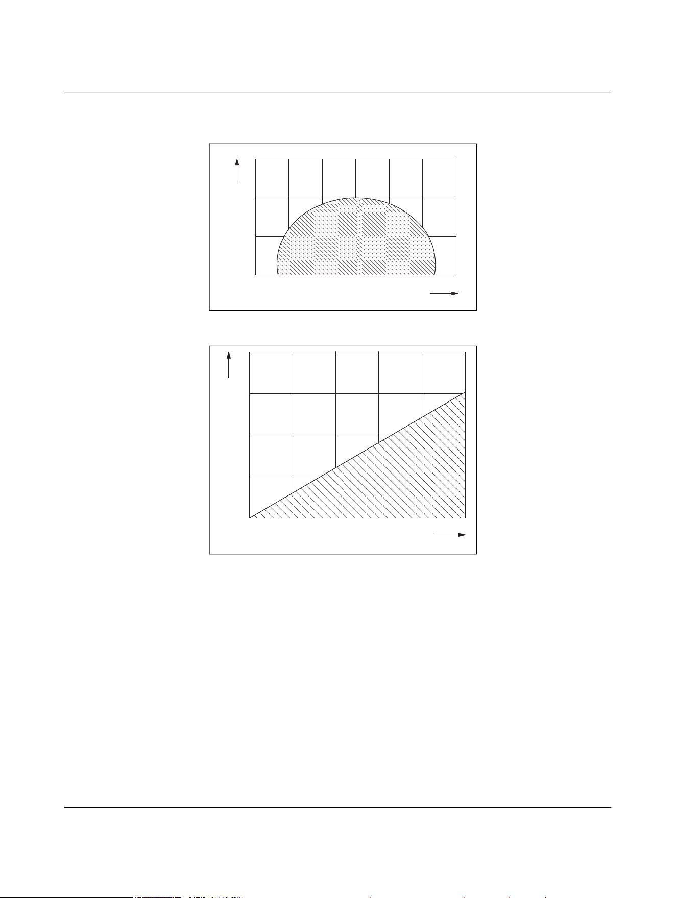
NEARFI 200/300
Figure 4-29 Transmission distance for lateral offset, NEARFI 200/300
Figure 4-30 Transmission distance for angular offset, NEARFI 200/300
-15 -10 -5 0 5 10 15
5
10
15
0
Transmission distance [mm]
Lateral offset [mm]
0
Angular offset [°]
Transmission distance [mm]
15
10
5
1086420
20
NEARFI
48 / 102 Phoenix Contact
110718_en_02
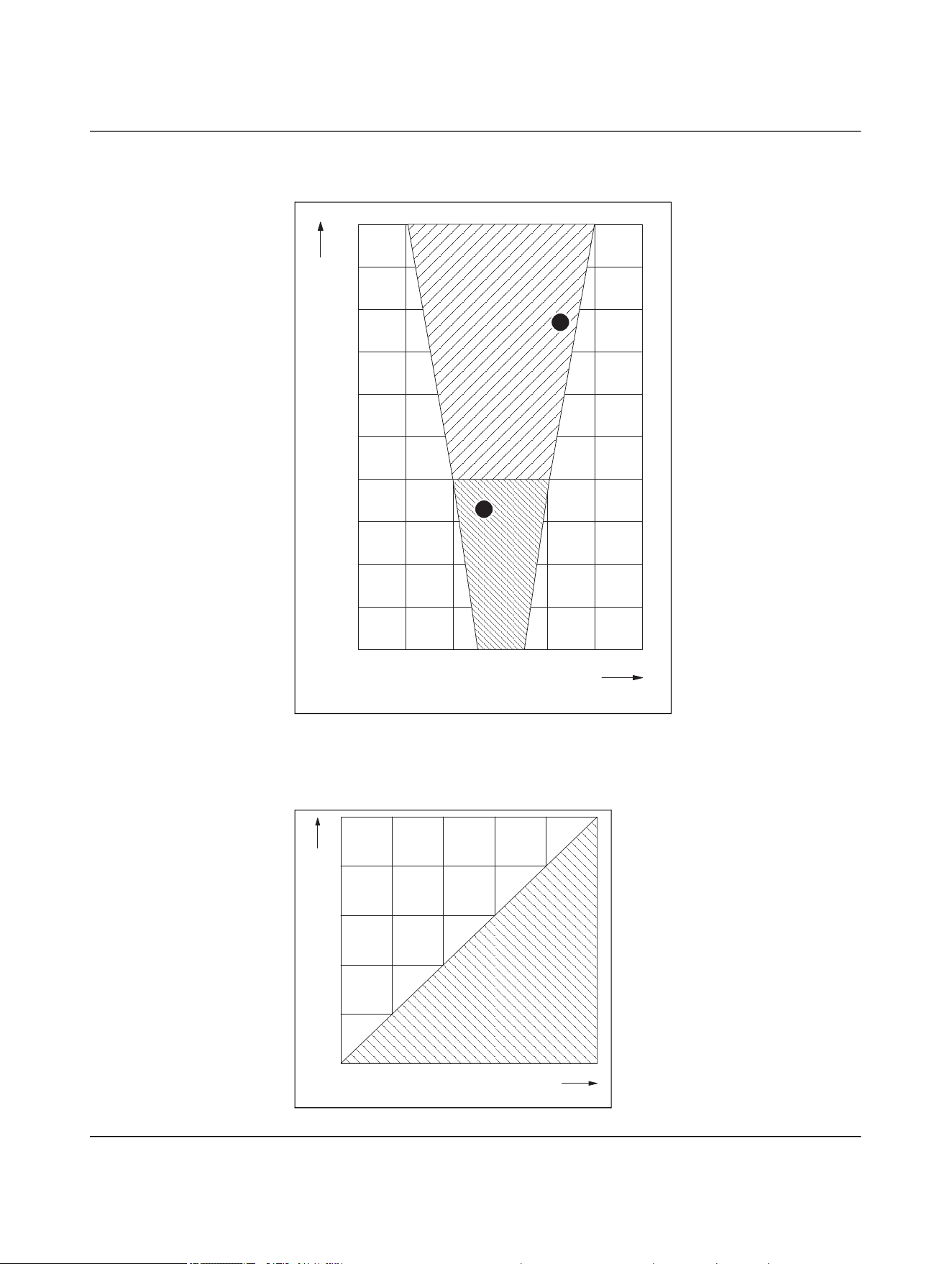
NEARFI 2000
Figure 4-31 Transmission distance for lateral offset, NEARFI 2000
Figure 4-32 Transmission distance for angular offset, NEARFI 2000
40 mm ... 100 mm (DIP 1 = ON)
0 mm ... 40 mm (DIP 1 = OFF)
-30 -20 -10 0 10 20 30
Lateral offset [mm]
0
10
20
30
40
50
60
70
80
90
100
Transmission distance [mm]
2
1
0 20 40 60 80 100
5
10
15
20
25
0
Angular offset [°]
Transmission distance [mm]

Product description
110718_en_02 Phoenix Contact 49 / 102
4.10 Obstacles in the air gap
Transmission through non-metallic materials is possible, e.g.,:
– Glass
– Plastic
– Oil, liquids
– Wood
The material thickness influences the attenuation and therefore the transmission
distance.
Example, NEARFI 2200:
Actual air gap + material thickness ≤ 10 mm
4.11 Foreign objects in the air gap
The impact of any foreign matter depends on the quantity of the material and the relevant
application.
Keep the air gap free of metallic soiling, such as metal shavings.
If metal foreign objects are present in the air gap, power transmission is stopped straight
away when there is no immediate response from the remote coupler. The foreign objects
remain at a thermally low mean value.
Metal dust
Metal dust that falls off the active surface or only adheres in small quantities has no sig-
nificant impact. However, if a large amount of ferromagnetic dust permanently adheres
to the active surface, e.g., in conjunction with a machine lubricant, transmission will be
adversely affected.
Cooling water
A small amount of cooling water that drips off or evaporates after a short time has little
effect on transmission. However, persistent wetting or a wall of water will impair data
transmission in the 60 GHz band.
Oil, machine lubricant
Oil or machine lubricant has little effect on transmission. The attenuation is negligible.
NEARFI
50 / 102 Phoenix Contact
110718_en_02
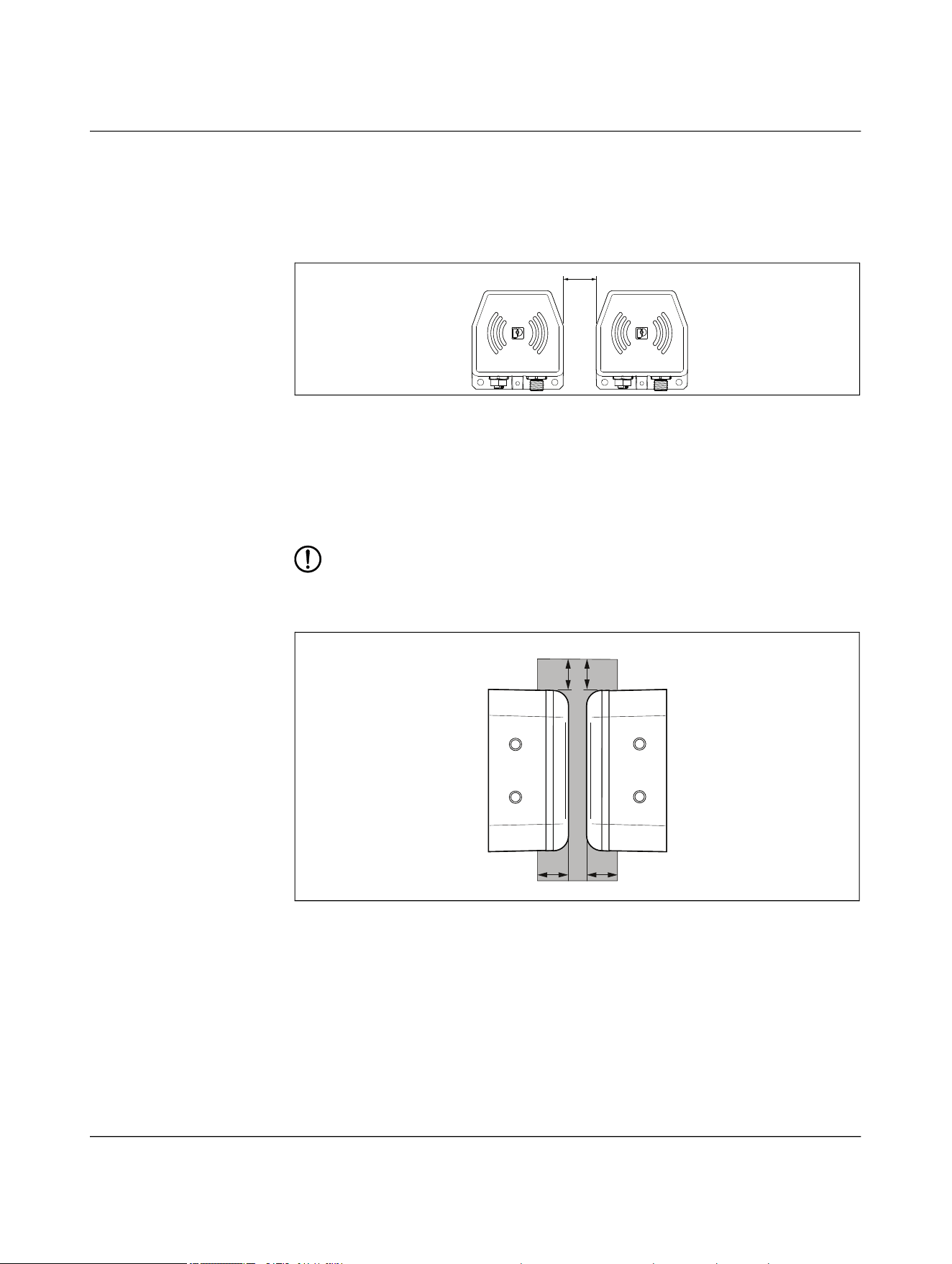
4.12 Minimum clearances
Maintain a minimum distance of 5 mm between the two opposing base and remote cou-
plers.
Figure 4-33 Minimum distance
c ≥ 5 mm
4.13 Installation in metal
The black plastic side of the devices is the active surface. The power coils are positioned
beneath this surface.
NOTE: Device damage
The device can heat up due to the effects of induction on the power coils.
– Maintain a minimum distance of 5 mm from metal objects.
Figure 4-34 Metal-free area
d ≥ 5 mm
C
X2 X1
d
d
d
d
metal-free
Product description
110718_en_02 Phoenix Contact 51 / 102
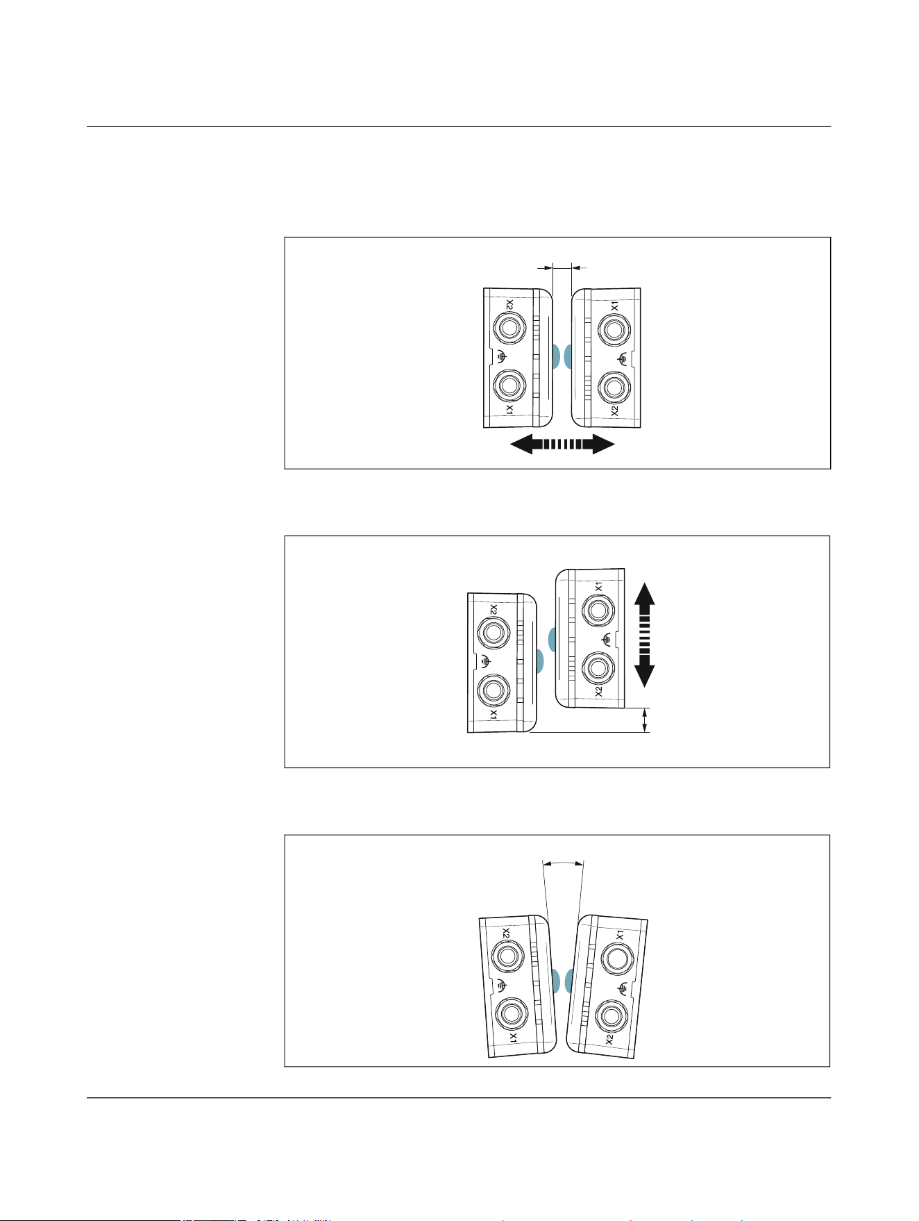
4.14 Coupling the base and remote couplers
Depending on the application, there are various ways of coupling the base and remote
couplers.
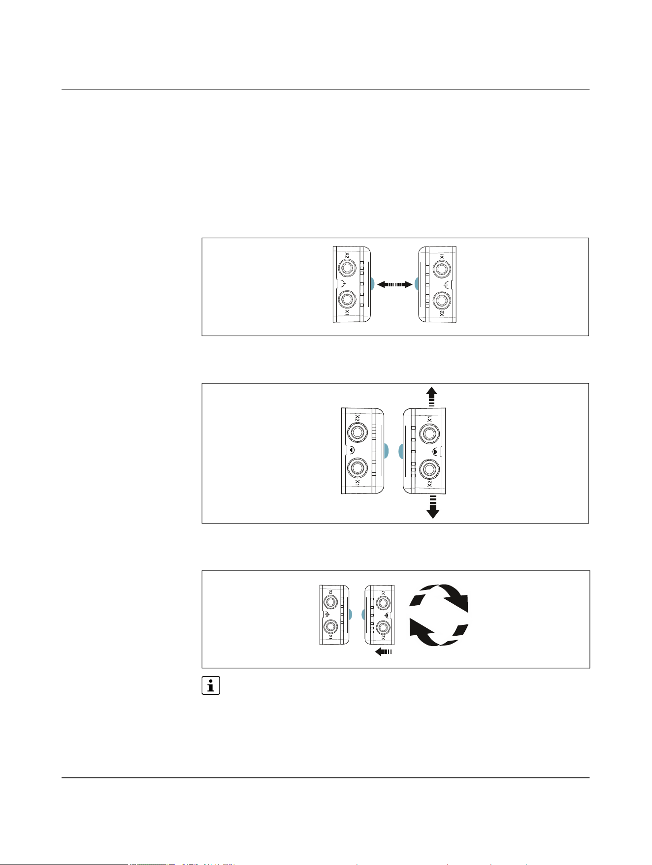
4.14.1 Individual operation
Frontal linear movement
Figure 4-35 Frontal linear movement
Lateral linear movement
Figure 4-36 Lateral linear movement
Sideways rotation
Figure 4-37 Sideways rotation
The operating range is limited in rotating applications. The maximum permissible
offset is ±2.5 mm. Parallel connection of several NearFi paths is not possible.
Remote
Base
Remote
Base
NEARFI
52 / 102 Phoenix Contact
110718_en_02
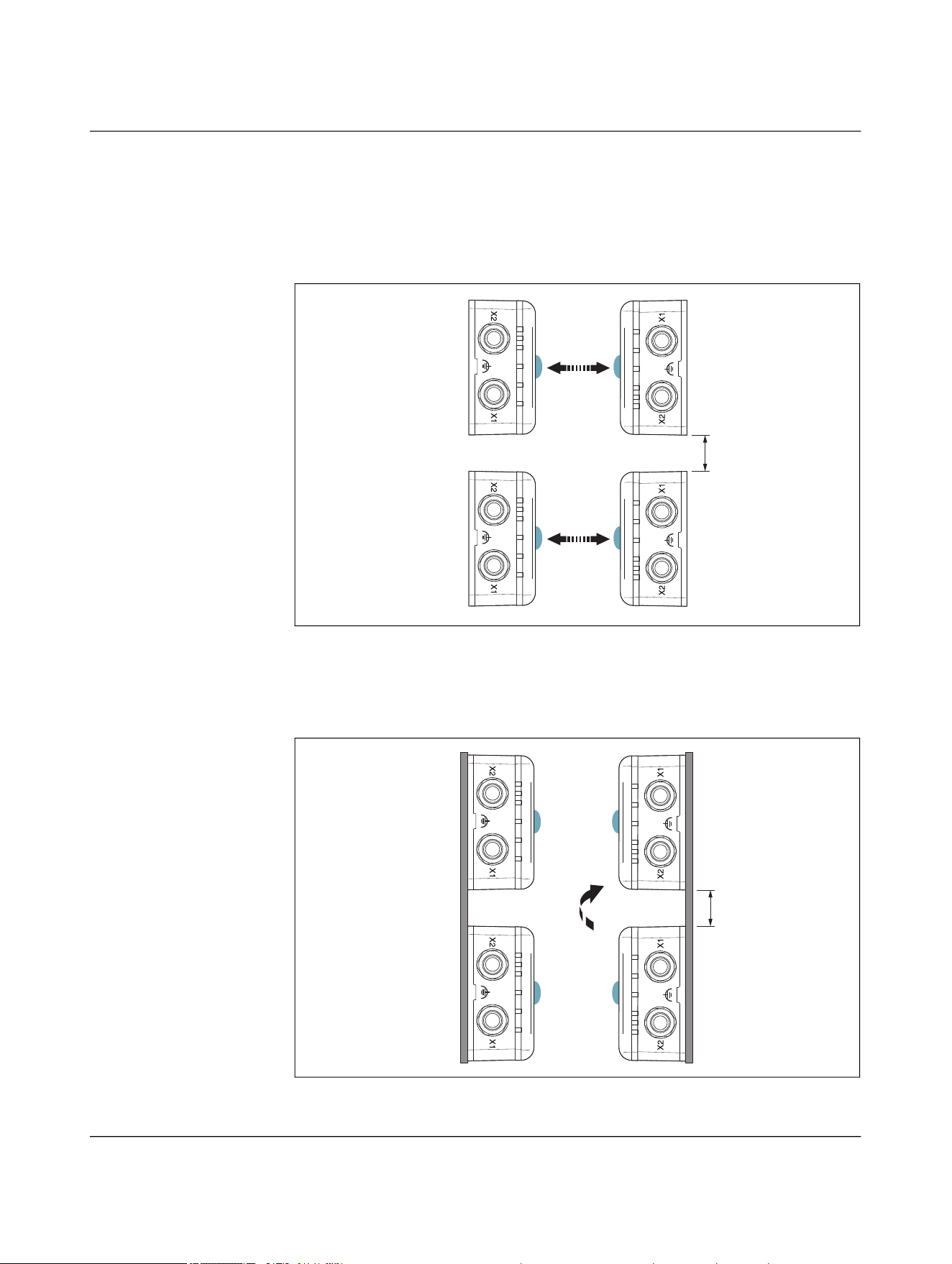
4.14.2 Parallel operation
Frontal linear movement
The base couplers are each mounted side by side with a clearance of five millimeters.
Coupling takes place simultaneously, e.g., for a robot tool change.
Figure 4-38 Front linear movement in parallel operation
Lateral linear movement
The base couplers are each mounted vertically one above the other with a clearance of
five millimeters. Coupling takes place simultaneously, e.g., for a rotary table.
Figure 4-39 Lateral linear movement in parallel operation
d
Remote
Base
Remote
Base
d
Remote
Base
Remote
Base
Product description
110718_en_02 Phoenix Contact 53 / 102
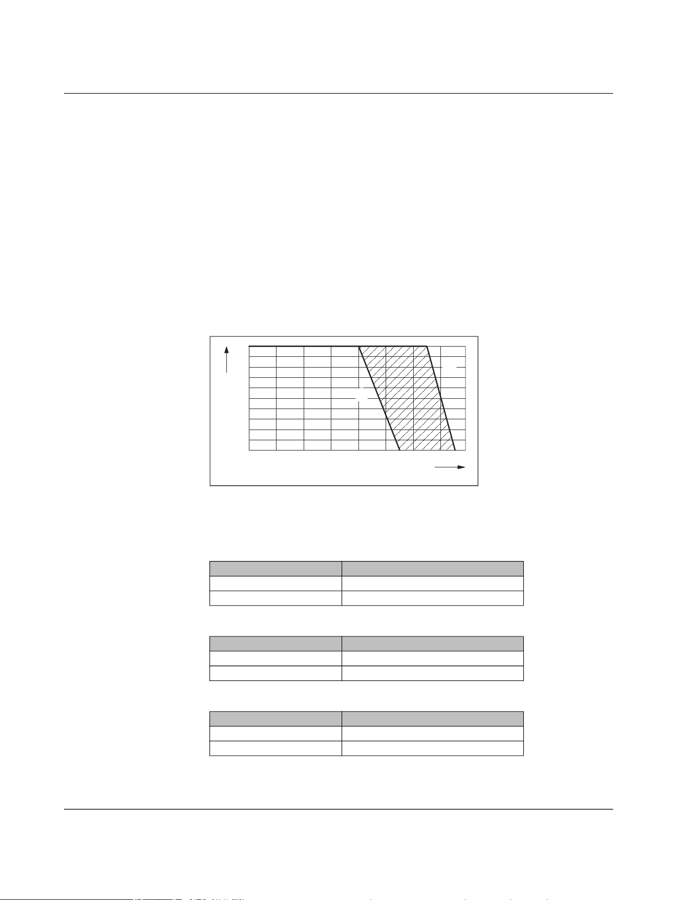
4.15 Derating
4.15.1 Derating curve
The derating curve shows the dependence of the maximum permissible ambient tem-
perature on the following factors:
– Thermal connection of the coupler housing
– Current strength or load at the remote output
The current strength is not dependent on the width of the air gap or the offset of the de-
vices.
Please note that the lower derating value of the respective item version applies for paral-
lel operation.
Power and data coupler (NEARFI 2200)
Figure 4-40 Derating curve
Power coupler US (NEARFI 200)
Power coupler UA (NEARFI 300)
Data coupler (NEARFI 2000)
Optimum thermal connection, see page 54
No thermal connection
Thermal connection Ambient temperature (operation)
Optimum, see page 54 ≤ 55°C
None ≤ 45°C
Thermal connection Ambient temperature (operation)
Optimum, see page 54 ≤ 60°C
None ≤ 50°C
Thermal connection Ambient temperature (operation)
Optimum, see page 54 ≤ 65°C
None ≤ 55°C
-20
-10
0
10 20 30 40 50 60
0
1,0
2,0
I [A]
Ą [°C]
ĵ
Ĵ
NEARFI
54 / 102 Phoenix Contact
110718_en_02
4.15.2 Thermal connection by mounting on metal
• Design the installation location such that the heat loss can be dissipated. Mount the
die-cast housing on a metal plate, heatsink, or similar heat-dissipating material.
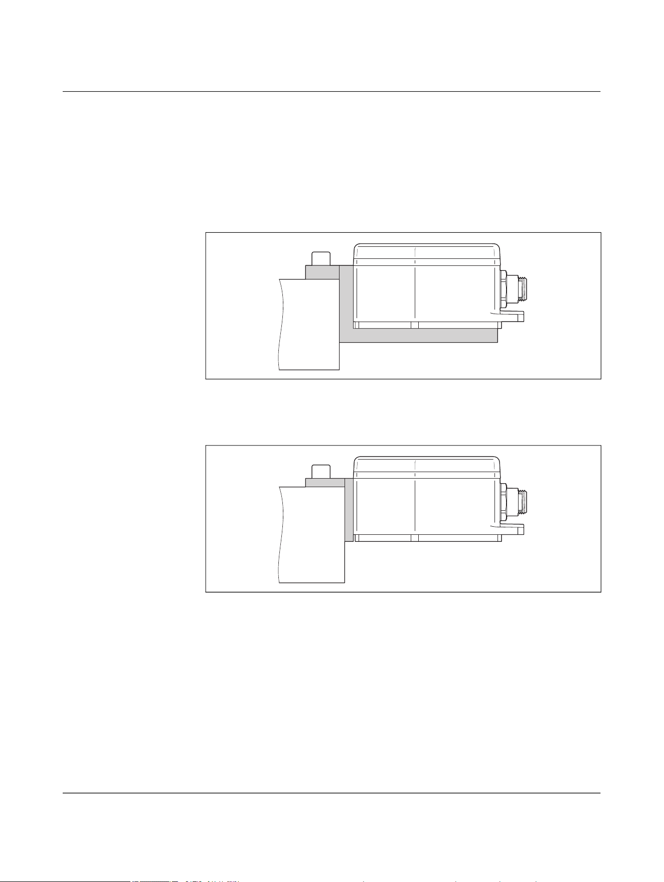
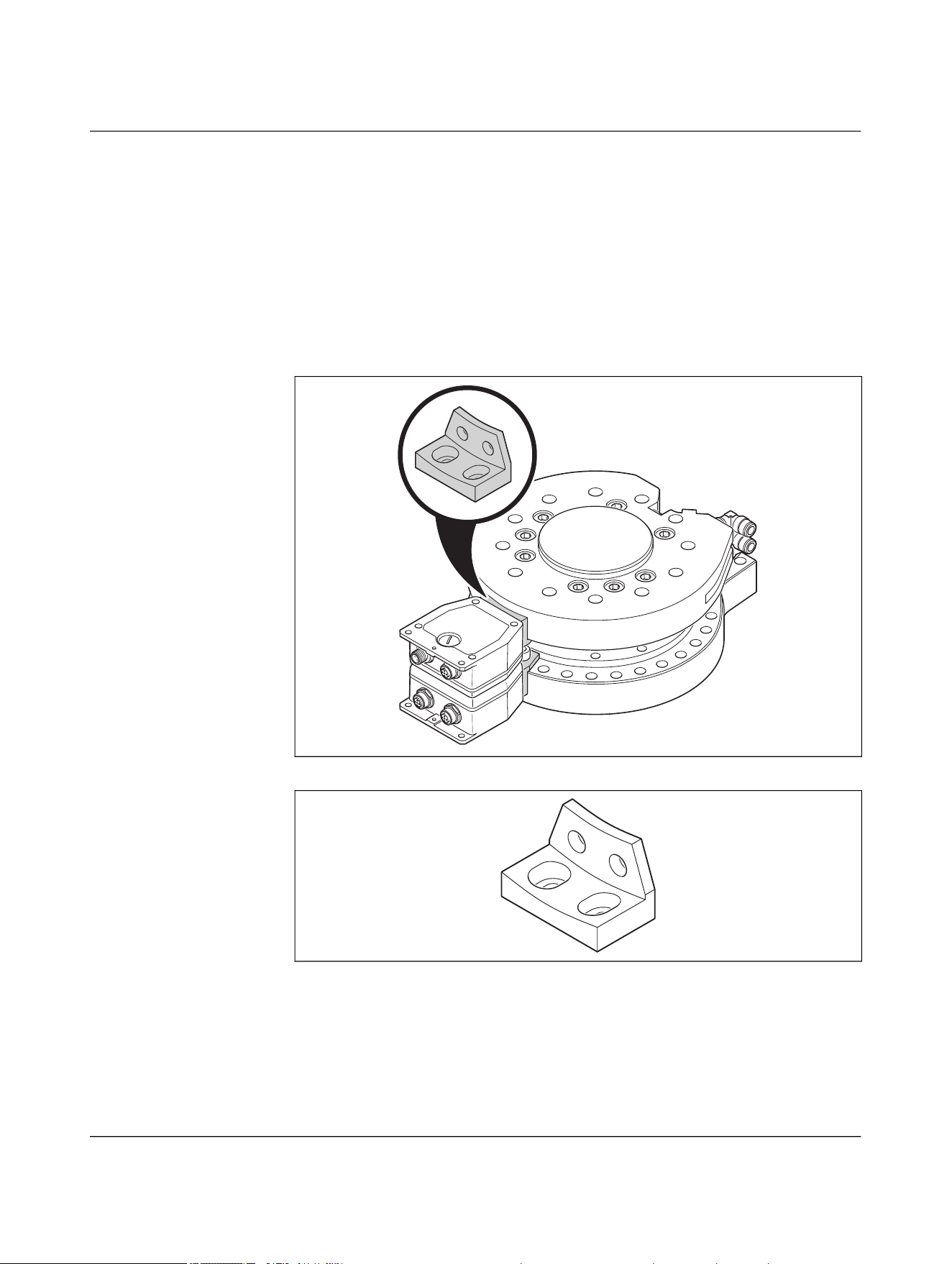
Optimal thermal connection
Mounting on 10 mm aluminum bracket on the front and bottom, surface bonded to solid
metal
Figure 4-41 Optimal thermal connection
Good thermal connection
Mounting on 5 mm aluminum bracket on the front, surface bonded to solid metal
Figure 4-42 Good thermal connection
No thermal connection
No thermal connection means that the device is mounted on plastic or another non-heat
conductive material.

Product description
110718_en_02 Phoenix Contact 55 / 102
4.15.3 Derating in accordance with UL
Power and data coupler (NEARFI 2200)
Power coupler (NEARFI 200 and NEARFI 300)
Data coupler (NEARFI 2000)
Thermal connection Load/output cur-
rent
Ambient temperature (operating)
in accordance with UL
Optimum, thermal connec-
tion via mounting adapter
and external heatsink
(machine head), see
page 56
0 A ≤ 55°C
2 A ≤ 40°C
Thermal connection Ambient temperature (operating) in
accordance with UL
Optimum, see page 54 ≤ 40°C
None ≤ 40°C
Thermal connection Ambient temperature (operating) in
accordance with UL
Optimum, see page 54 ≤ 65°C
None ≤ 55°C
NEARFI
56 / 102 Phoenix Contact
110718_en_02
4.15.3.1 Mounting NEARFI 2200 in accordance with UL
UL CONDITIONS OF ACCEPTABILITY for:
– NEARFI 2200 B (base)
– NEARFI 2200 R (remote)
These products were tested with an external thermal connection (adapter) and hard an-
odized aluminum heatsink (machine head). See figures below for details.
The following tests shall be performed in the end-product evaluation, if a different exter-
nal thermal connection or heatsink is used:
– TEMPERATURE TEST (10.1-10.4) (UL/CSA 61010-1, UL/CSA 61010-2-201)
Figure 4-43 Installation example with external heatsink (processing head)
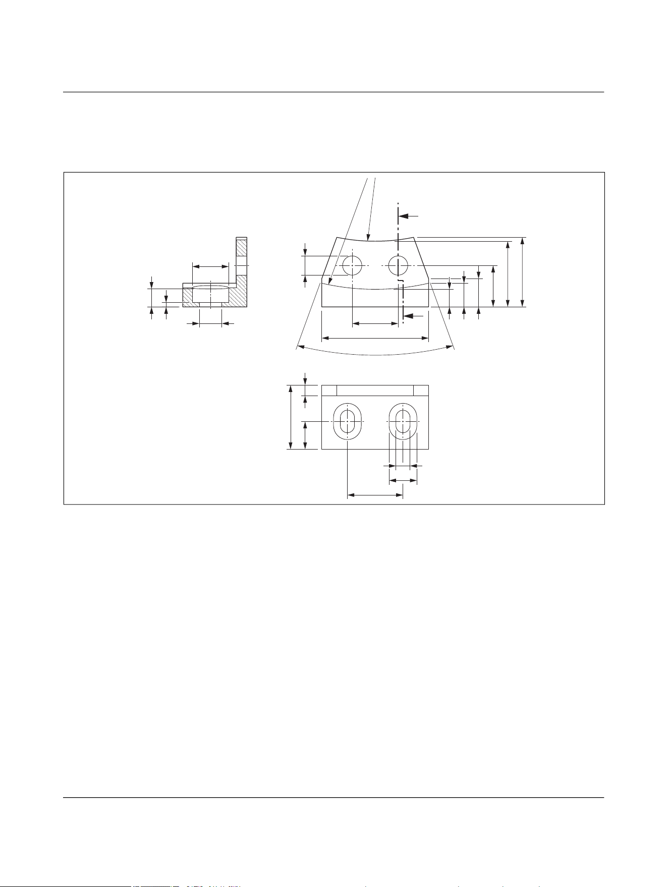
Figure 4-44 Adapter

NEARFI
58 / 102 Phoenix Contact
110718_en_02
5 Installation
5.1 Mounting and removal
CAUTION:
Observe the safety notes in Section “For your safety” on page 5.
NOTE: Device damage
– Only mount and remove devices when the power supply is disconnected.
– Mount the device on a flat, load-bearing surface or profile.
– Use standard M5 or M6 screws (ISO 4762 or hexalobular internal screws) and
spring washers.
– Observe the maximum torque of the screws.
– Select the installation location so that metal objects cannot enter the air gap be-
tween the base and the remote.
You can secure the devices in three different ways. This allows the devices to be mounted
flexibly, e.g., on a profile or bracket, on a machine, etc.
– 5.1.1 “Mounting with two M5 screws”
– 5.1.2 “Mounting with four M6 screws”
– 5.1.3 “Mounting with two M6 screws”
Rotating applications
• Center the base and remote couplers as accurately as possible. The manufacturer
logo “P” marks the center.
• A template for centering the devices can be found here: Figure 9-2 “Centering tem-
plate”
Installation
110718_en_02 Phoenix Contact 59 / 102
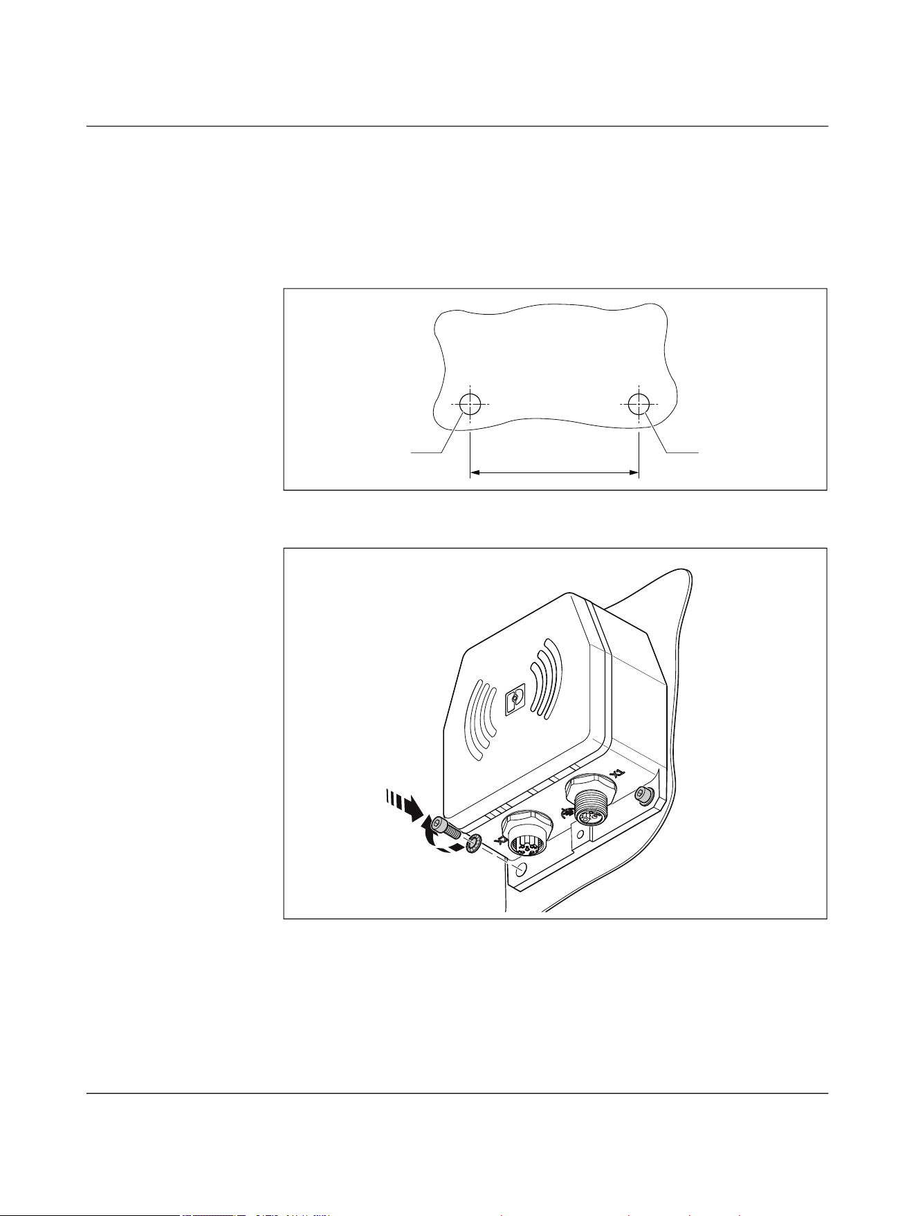
5.1.1 Mounting with two M5 screws
• Mark the drill holes on the mounting surface and drill the holes.
• Drill the holes with the specified diameter.
• Secure the die-cast housing with two M5 screws and spring washers.
• Check that the die-cast housing is securely mounted.
Figure 5-1 Drilling diagram
Figure 5-2 Mounting with two M5 screws
65
Ø5,5 Ø5,5
A
B
NEARFI
60 / 102 Phoenix Contact
110718_en_02
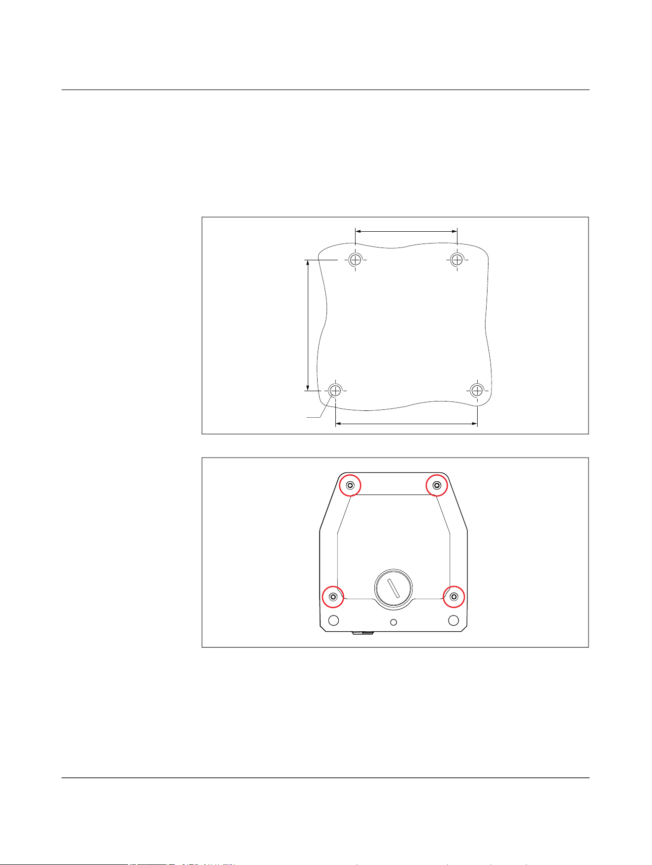
5.1.2 Mounting with four M6 screws
If the operating conditions are particularly difficult, e.g., due to vibrations, you can also
mount the device with four M6 screws.
• Fix the die-cast housing in place using four screws and four spring washers
Female thread, thread depth = 7 mm, tightening torque 0.7 Nm
• Check that the die-cast housing is securely mounted.
Figure 5-3 Drilling diagram
Figure 5-4 Mounting with four M6 screws
M6
65,5
47
61
Installation
110718_en_02 Phoenix Contact 61 / 102
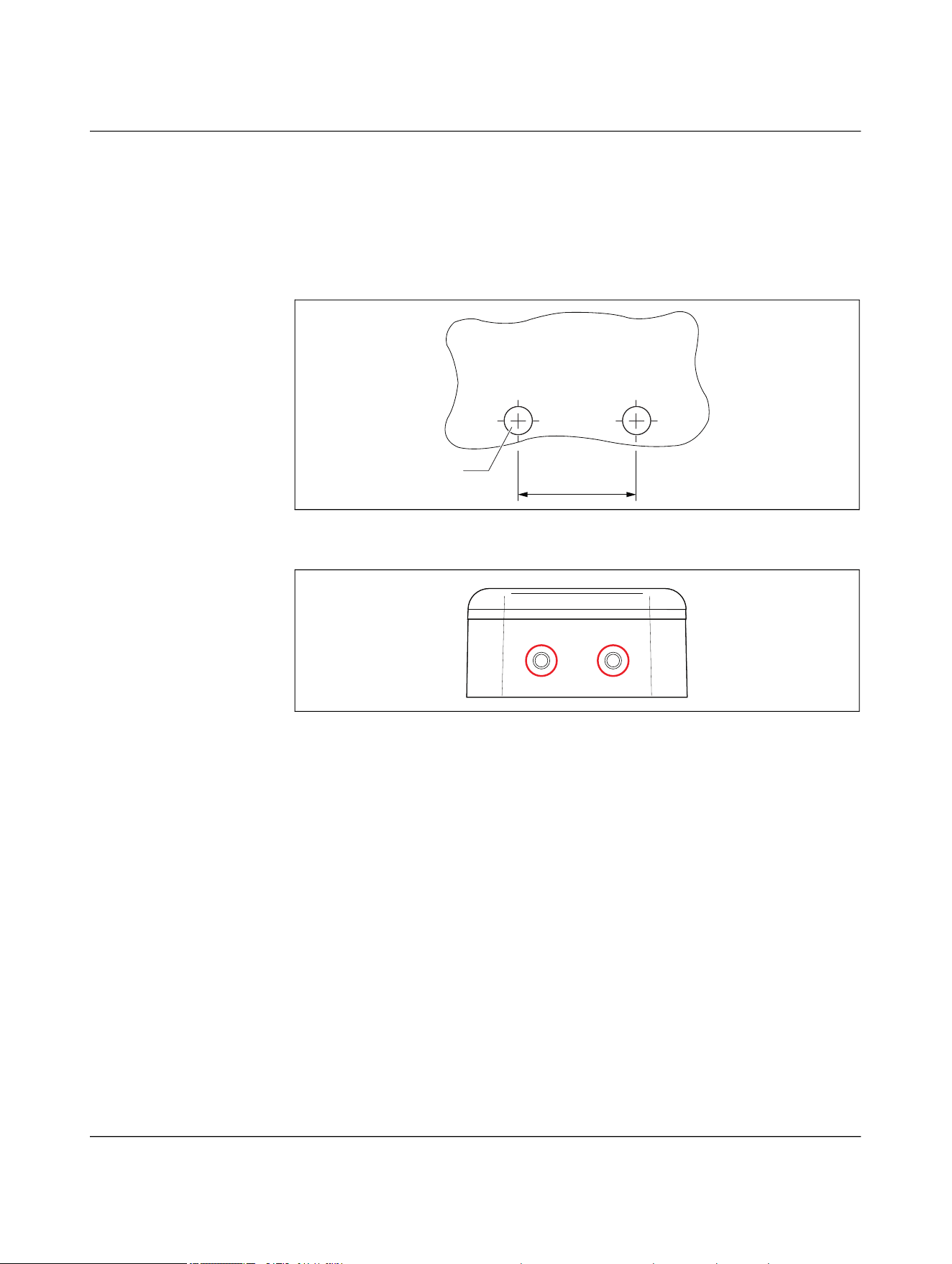
5.1.3 Mounting with two M6 screws
You can also mount the device from above with two M6 screws.
• Secure the die-cast housing with two M6 screws.
Female thread, thread depth = 7 mm, tightening torque 0.7 Nm
• Check that the die-cast housing is securely mounted.
Figure 5-5 Drilling diagram
Figure 5-6 Mounting with two M6 screws
5.1.4 Removal
• Disconnect all cables from the device.
• Loosen the mounting screws.
26
M6

NEARFI
62 / 102 Phoenix Contact
110718_en_02
5.2 Connecting cables
• Put protective caps on unused connection sockets to ensure an IP65 degree of pro-
tection.
• To prevent untight seals and damage, tighten the M12 connectors to the recom-
mended tightening torque.
– Recommended tightening torque: 0.4 Nm
5.2.1 Calculating the cable lengths
The voltage drop on the cables is calculated according to the following formula:
U
A
= I × R × 2
Example 1
Line resistance of a 4 x 1.5 mm² power supply cable, cable type 105 (e.g., SAC-4P-...-
105/M12FSL) = 12 Ω/km
– At 2 A:
U
A
= 2 A × 12 Ω/km × 2 = 48 V/km
Corresponds to 0.48 V for 10 m
Example 2
Line resistance of a 4 x 2.5 mm² power supply cable, cable type PUR (e.g., SAC-4P-...-
PUR/M12FSL) = 7 Ω/km
– At 1.5 A:
U
A
= 1.5 A × 7 Ω/km × 2 = 21 V/km
Corresponds to 0.21 V for 10 m
Installation
110718_en_02 Phoenix Contact 63 / 102
5.2.2 Pin assignment for NEARFI 2200
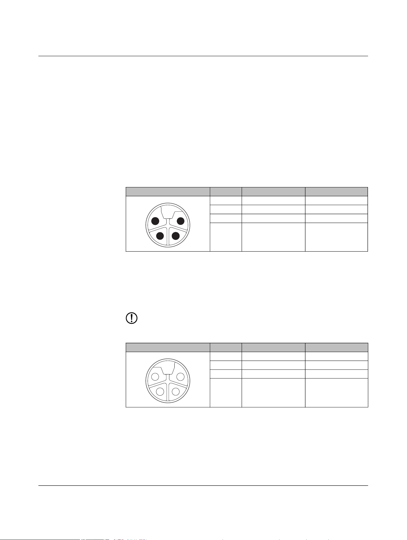
5.2.2.1 Base: Connection X1 (power IN)
The base coupler is supplied via connection X1 (power IN).
– Supply voltage +24 V DC (US)
– Reference potential GND (US)
The NEARFI 2200 B base coupler transmits the voltage US to the NEARFI 2200 R remote
coupler without contact.
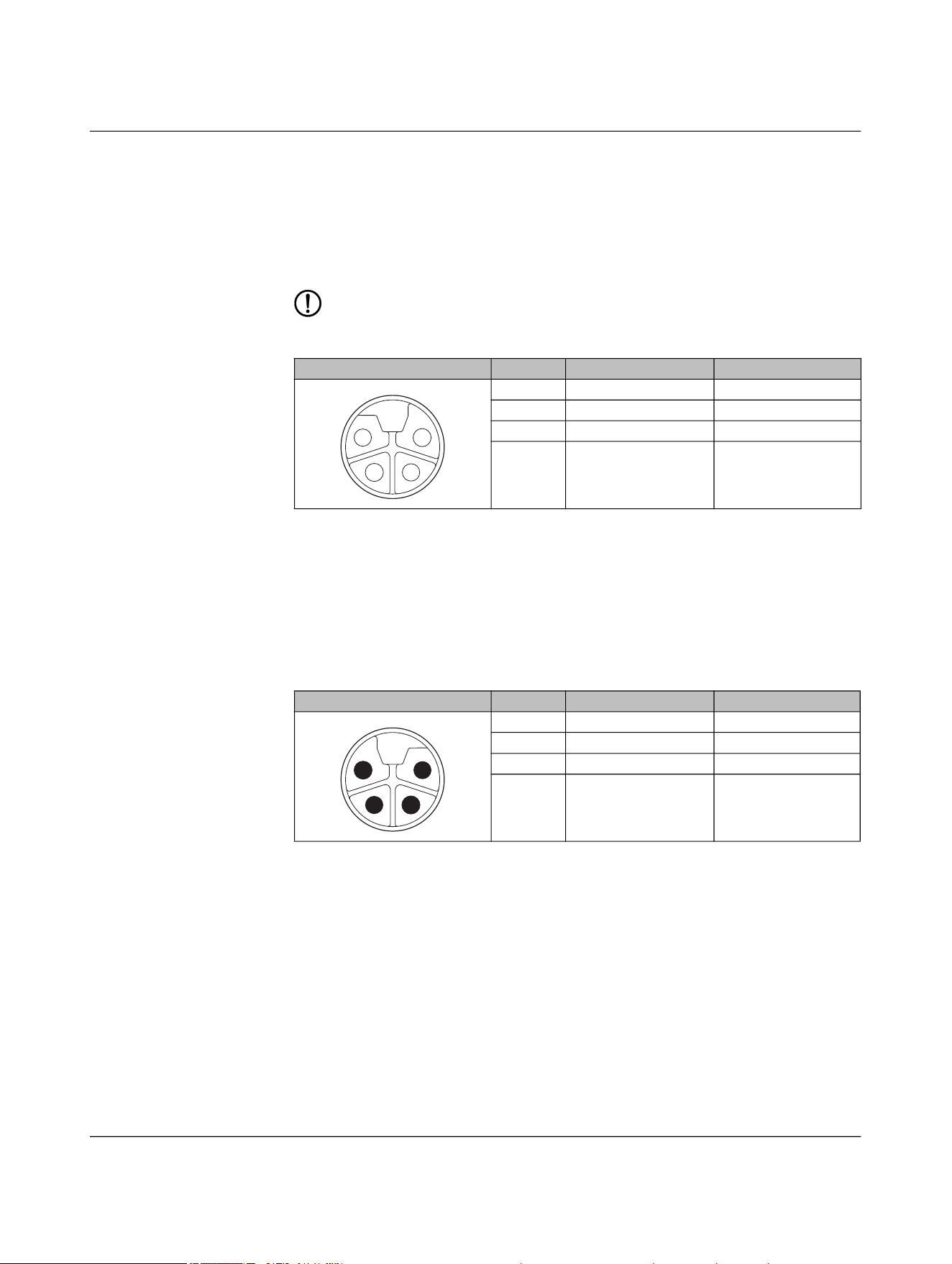
5.2.2.2 Remote: Connection X1 (power OUT)
DC voltage is provided at output X1 (power OUT) of the remote coupler.
The output is protected electronically from overload and short circuit. In case of a fault,
the output voltage is limited to < 30 V DC (EN 61131-2).
NOTE: Device damage
Never apply voltage to the output X1 (power OUT) of the remote coupler.
Table 5-1 Power IN (X1), M12 male, L-coded
Pin IN Wire color
1 +24 V DC (U
S
) Brown
2 Not used White
3 GND (U
S
) Blue
4 Not used Black
Table 5-2 Power OUT (X1), M12 female, L-coded
Pin OUT Wire color
1 +24 V DC (U
S
) Brown
2 Not used White
3 GND (U
S
) Blue
4 Not used Black
1
2
3
4
4
3
2
1
NEARFI
64 / 102 Phoenix Contact
110718_en_02
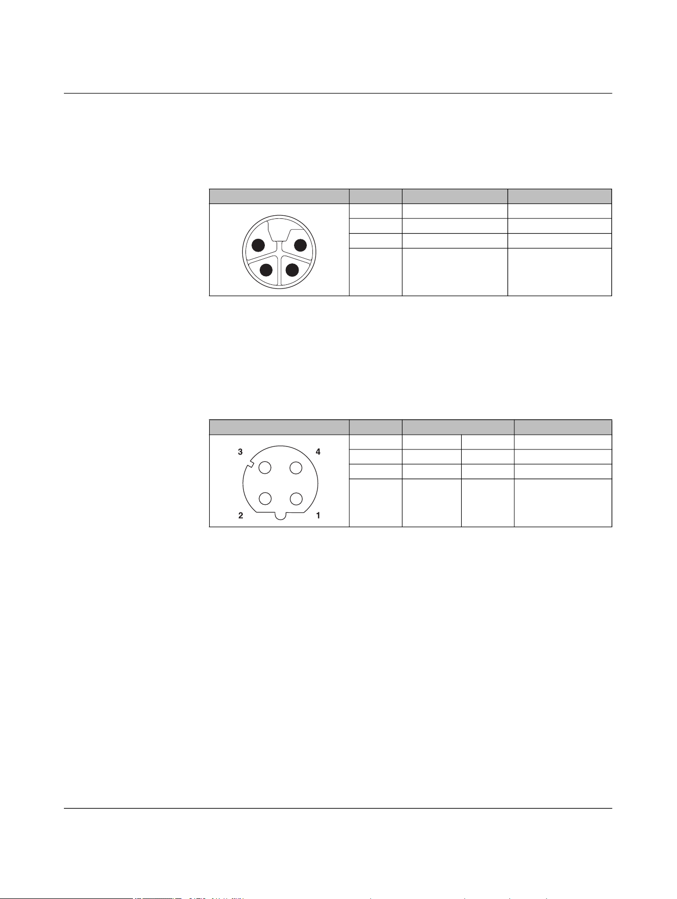
5.2.2.3 Base and remote: Connection X2 (data IN/OUT)
You connect the Ethernet network via the circular connector X2 (data IN/OUT).
The shield is connected to FE in the device. The thread is used for additional shielding.
• Make the FE connection with mounting screws.
• Only use shielded twisted pair cables and corresponding shielded M12 males.
Table 5-3 Data IN/OUT (X2), M12 female, D-coded
Pin IN/OUT Wire color (T568B)
1 Send TX+ White-orange
2 Receive RX+ White-green
3 Send TX- Orange
4 Receive RX- Green
Installation
110718_en_02 Phoenix Contact 65 / 102
5.2.3 Pin assignment for NEARFI 200
5.2.3.1 Base: Connection X1 (power IN)
The base coupler is supplied via connection X1 (power IN).
You can connect two supply voltages to the connector:
– Supply voltage 1: +24 V DC (U
S
) and reference potential GND (U
S
)
– Supply voltage 2: +24 V DC (U
A
) and reference potential GND (U
A
)
Both supply voltages are electrically isolated from one another and from functional
ground. Each pin of connector X1 (power IN) is connected to the same pin of socket X2
(power OUT). This enables the supply to be forwarded to the next device.
– The NEARFI 200 couplers transmit the communications and sensor voltage US via
the air.
– The UA actuator voltage is only forwarded via the connectors.
5.2.3.2 Base: Connection X2 (power OUT)
Connection X2 (power OUT) enables the supply voltage to be forwarded to the next de-
vice.
The output is protected electronically from overload and short circuit. In case of a fault,
the output voltage is limited to < 30 V DC (EN 61131-2).
NOTE: Device damage
Never apply voltage to the output of the base coupler.
Table 5-4 Power IN (X1), M12 male, L-coded
Pin IN Wire color
1 +24 V DC (U
S
) Brown
2 GND (U
A
) White
3 GND (U
S
) Blue
4 +24 V DC (U
A
) Black
Table 5-5 Power OUT (X2), M12 female, L-coded
Pin OUT Wire color
1 +24 V DC (U
S
) Brown
2 GND (U
A
) White
3 GND (U
S
) Blue
4 +24 V DC (U
A
) Black
1
2
3
4
4
3
2
1
NEARFI
66 / 102 Phoenix Contact
110718_en_02
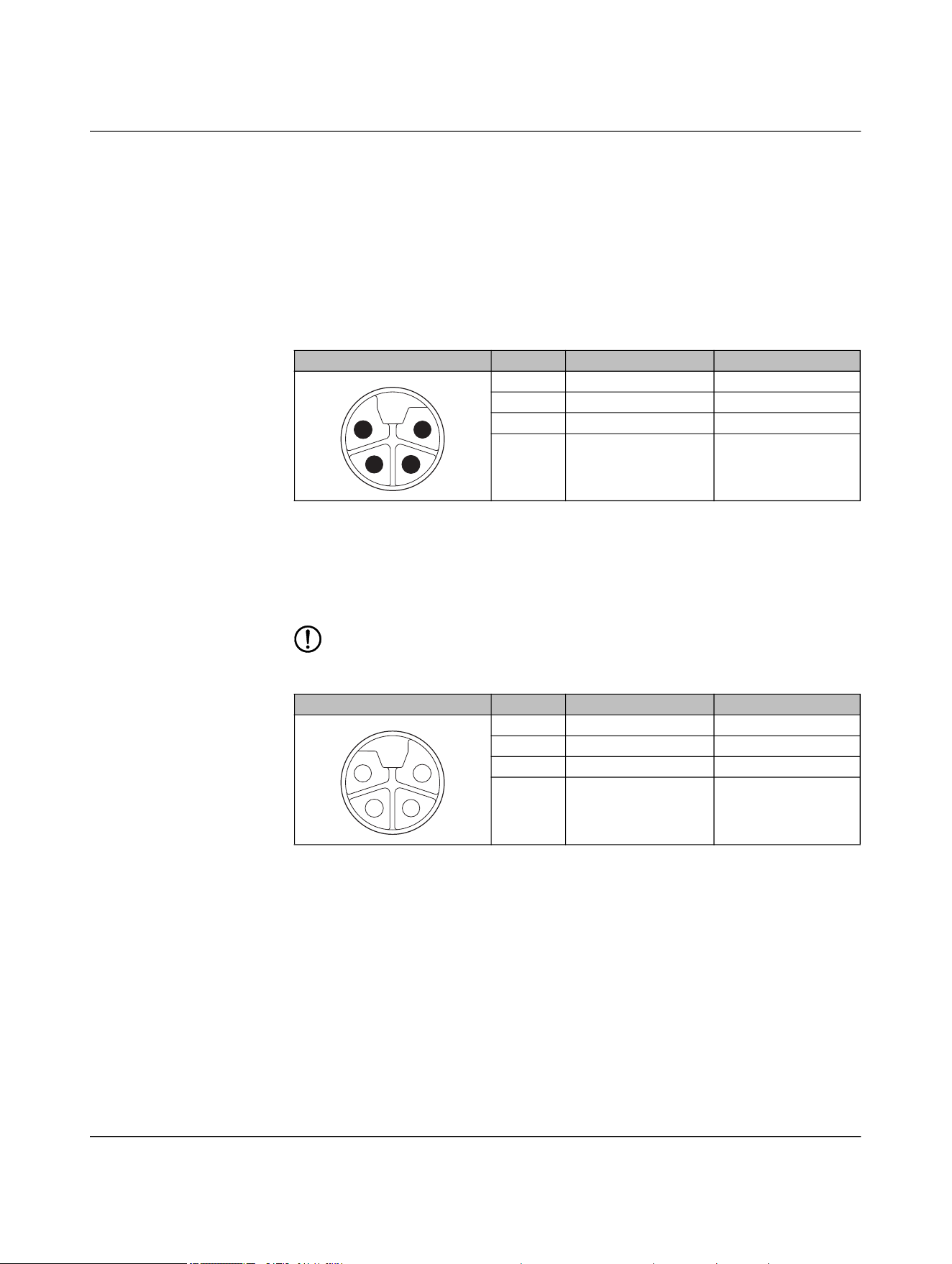
5.2.3.3 Remote: Connection X1 (power OUT)
DC voltage is provided at output X1 of the remote coupler:
– Up to 50 W, US in stand-alone operation
– Up to 100 W, US in parallel operation
The output is protected electronically from overload and short circuit. In case of a fault,
the output voltage is limited to < 30 V DC (EN 61131-2).
NOTE: Device damage
Never apply voltage to the output of the remote coupler.
5.2.3.4 Remote: Connection X2 (power IN)
You can connect the remote coupler to a second remote coupler connected in parallel via
connection X2 (power IN).
Each pin of connector X2 (power IN) is connected to the same pin of socket X1 (power
OUT). This enables the supply voltage to be forwarded to the remote output X1 (power
OUT).
Table 5-6 Power OUT (X1), M12 female, L-coded
Pin OUT Wire color
1 +24 V DC (U
S
) Brown
2 GND (U
A
) White
3 GND (U
S
) Blue
4 +24 V DC (U
A
) Black
Table 5-7 Power IN (X2), M12 male, L-coded
Pin IN Wire color
1 +24 V DC (U
S
) Brown
2 GND (U
A
) White
3 GND (U
S
) Blue
4 +24 V DC (U
A
) Black
4
3
2
1
1
2
3
4
Installation
110718_en_02 Phoenix Contact 67 / 102
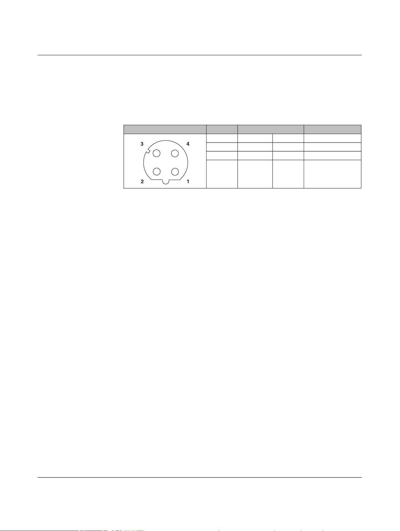
5.2.4 Pin assignment for NEARFI 300
5.2.4.1 Base: Connection X1 (power IN)
The base coupler is supplied via connection X1 (power IN).
You can connect two supply voltages to the connector:
– Supply voltage 1: +24 V DC (U
S
) and reference potential GND (U
S
)
– Supply voltage 2: +24 V DC (U
A
) and reference potential GND (U
A
)
Both supply voltages are electrically isolated from one another and from functional
ground. Each pin of connector X1 (power IN) is connected to the same pin of socket X2
(power OUT). This enables the supply to be forwarded to the next device.
– The NEARFI 300 couplers transmit the actuator voltage UA via the air.
– The communications and sensor voltage US is only forwarded via the connectors.
5.2.4.2 Base: Connection X2 (Power-OUT)
Connection X2 (power OUT) enables the supply voltage to be forwarded to the next de-
vice.
The output is protected electronically from overload and short circuit. In case of a fault,
the output voltage is limited to < 30 V DC (EN 61131-2).
NOTE: Device damage
Never apply voltage to the output of the base coupler.
Table 5-8 Power IN (X1), M12 male, L-coded
Pin IN Wire color
1 +24 V DC (U
S
) Brown
2 GND (U
A
) White
3 GND (U
S
) Blue
4 +24 V DC (U
A
) Black
Table 5-9 Power-OUT (X2), M12 female, L-coded
Pin OUT Wire color
1 +24 V DC (U
S
) Brown
2 GND (U
A
) White
3 GND (U
S
) Blue
4 +24 V DC (U
A
) Black
1
2
3
4
4
3
2
1

NEARFI
68 / 102 Phoenix Contact
110718_en_02
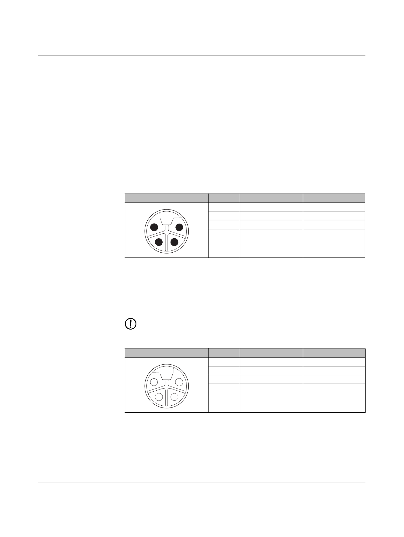
5.2.4.3 Remote: Connection X1 (power OUT)
DC voltage is provided at output X1 of the remote coupler:
– Up to 50 W, UA in stand-alone operation
– Two DC voltages, US and UA in parallel operation
The output is protected electronically from overload and short circuit. In case of a fault,
the output voltage is limited to < 30 V DC (EN 61131-2).
NOTE: Device damage
Never apply voltage to the output of the remote coupler.
5.2.4.4 Remote: Connection X2 (power IN)
You can connect the remote coupler to a second remote coupler connected in parallel via
connection X2 (power IN).
Each pin of connector X2 (power IN) is connected to the same pin of socket X1 (power
OUT). This enables the supply voltage to be forwarded to the remote output X1 (power
OUT).
Table 5-10 Power OUT (X1), M12 female, L-coded
Pin OUT Wire color
1 +24 V DC (U
S
) Brown
2 GND (U
A
) White
3 GND (U
S
) Blue
4 +24 V DC (U
A
) Black
Table 5-11 Power IN (X2), M12 male, L-coded
Pin IN Wire color
1 +24 V DC (U
S
) Brown
2 GND (U
A
) White
3 GND (U
S
) Blue
4 +24 V DC (U
A
) Black
4
3
2
1
1
2
3
4
Installation
110718_en_02 Phoenix Contact 69 / 102
5.2.5 Pin assignment for NEARFI 2000
5.2.5.1 Base and remote: Connection X1 (power IN)
The data couplers are supplied via the X1 circular connector (power IN).
5.2.5.2 Base and remote: Connection X2 (data IN/OUT)
You connect the Ethernet network via the circular connector X2 (data IN/OUT).
The shield is connected to FE in the device. The thread is used for additional shielding.
• Make the FE connection with mounting screws.
• Only use shielded twisted pair cables and corresponding shielded M12 males.
Table 5-12 Power IN (X1), M12 male, L-coded
Pin IN Wire color
1 +24 V DC (U
S
) Brown
2 Not used White
3 GND (U
S
) Blue
4 Not used Black
Table 5-13 Data IN/OUT (X2), M12 female, D-coded
Pin IN/OUT Wire color (T568B)
1 Send TX+ White-orange
2 Receive RX+ White-green
3 Send TX- Orange
4 Receive RX- Green
1
2
3
4

NEARFI
70 / 102 Phoenix Contact
110718_en_02
5.2.6 Circular connectors
Depending on the device and the accessories used, you can plug in or screw the connec-
tion via push-pull.
Table 5-14 Circular connectors
NEARFI... Connection Meaning M12 Coding Connection method
2200 B
X1 Power IN Male L
Push-pull fast connection or
screw connection
X2 Ethernet Female D
2200 R
X1 Power OUT (US) Female L Screw connection
X2 Ethernet Female D
Push-pull fast connection or
screw connection
200 B
X1 Power IN Male L
Push-pull fast connection or
screw connection
X2 Power OUT Female L Screw connection
200 R
X1 Power OUT (US) Female L Screw connection
X2 Power IN Male L
Push-pull fast connection or
screw connection
300 B
X1 Power IN Male L
Push-pull fast connection or
screw connection
X2 Power OUT Female L Screw connection
300 R
X1 Power OUT (UA) Female L Screw connection
X2 Power IN Male L
Push-pull fast connection or
screw connection
2000 B
X1 Power IN Male L
Push-pull fast connection or
screw connection
X2 Ethernet Female D
2000 R
X1 Power IN Male L
Push-pull fast connection or
screw connection
X2 Ethernet Female D
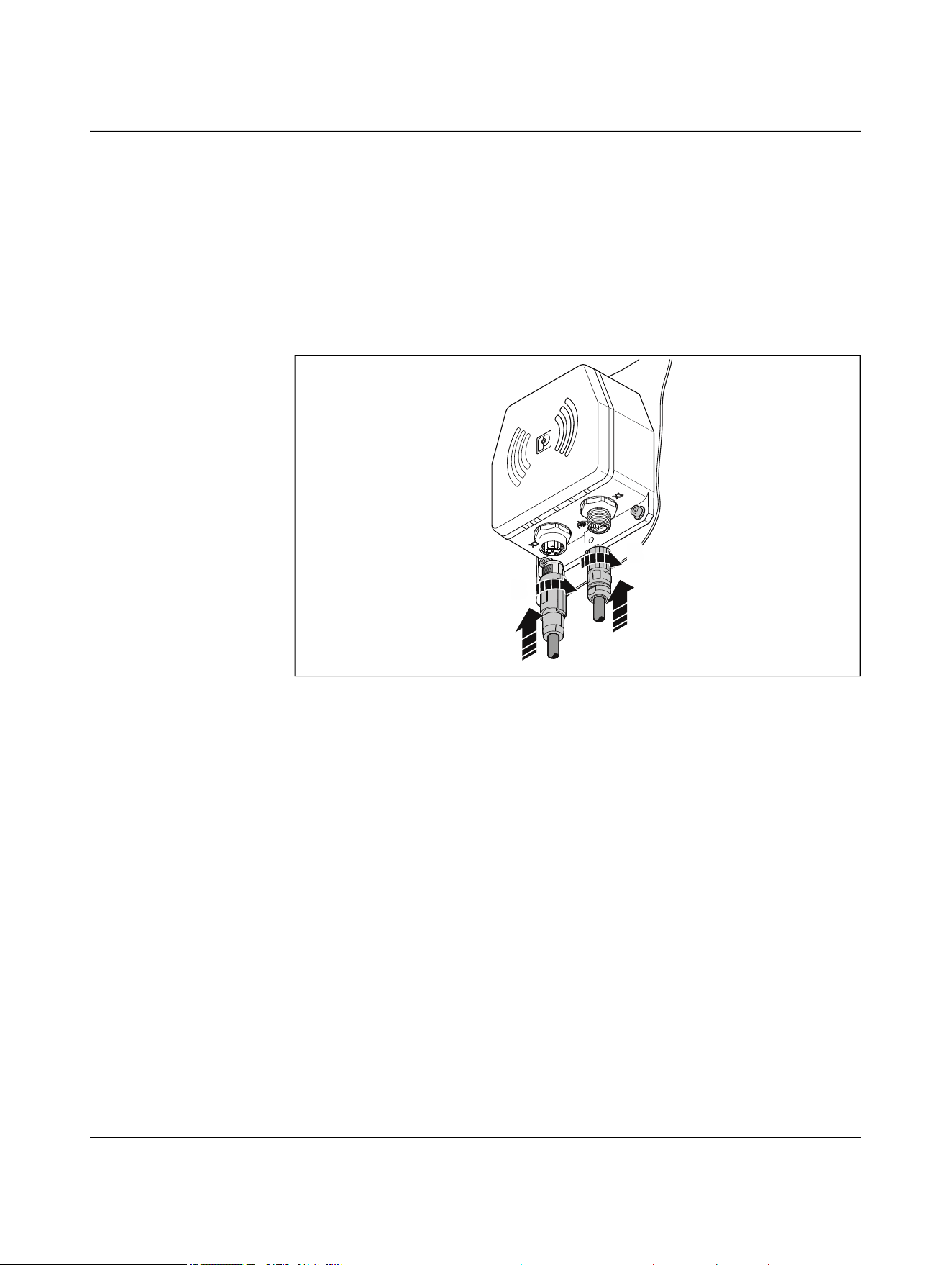
Installation
110718_en_02 Phoenix Contact 71 / 102
The device-side circular connectors are coded. It is impossible to accidentally connect
power connector X1 and Ethernet connector X2 incorrectly.
• Plug the field-side circular connectors fully onto the connections on the device.
• To affix the plug, tighten the union nut hand-tight.
• Ensure the connection cable has sufficient strain relief in accordance with the con-
ductor cross-section.
• On the NEARFI 200/300, one M12 port is sealed with a filler plug in the delivery state.
For stand-alone operation, only one M12 port is required. If you want to operate the
devices in parallel, remove the filler plug.
Figure 5-7 Connecting cables
A
B
A
B
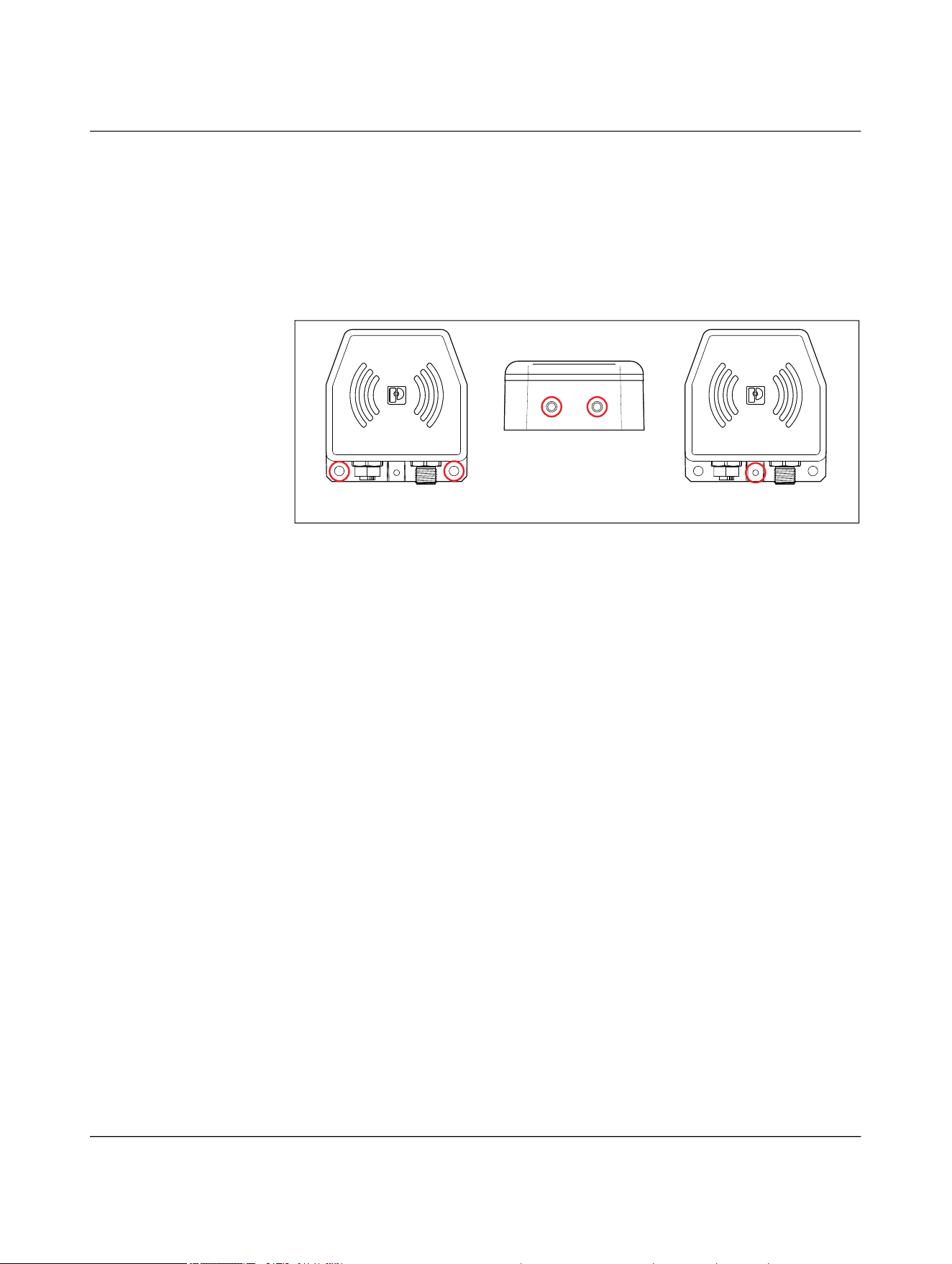
NEARFI
72 / 102 Phoenix Contact
110718_en_02
5.2.7 Functional ground
There are three different ways to ground the device:
– Via the mounting screws at the bottom, with toothed lock washer
– Via the mounting screws at the top
– Via the grounding connection with an M4 screw and toothed lock washer
Female thread, thread depth = 5 mm, tightening torque 0.6 Nm
Figure 5-8 Options for functional grounding
5.3 Startup and maintenance
When you switch on the power supply on the base side, the coupling link is automatically
ready for operation.
• Check the area between the base and remote coupler regularly.
• Keep this area free of metallic soiling, such as metal shavings.
123
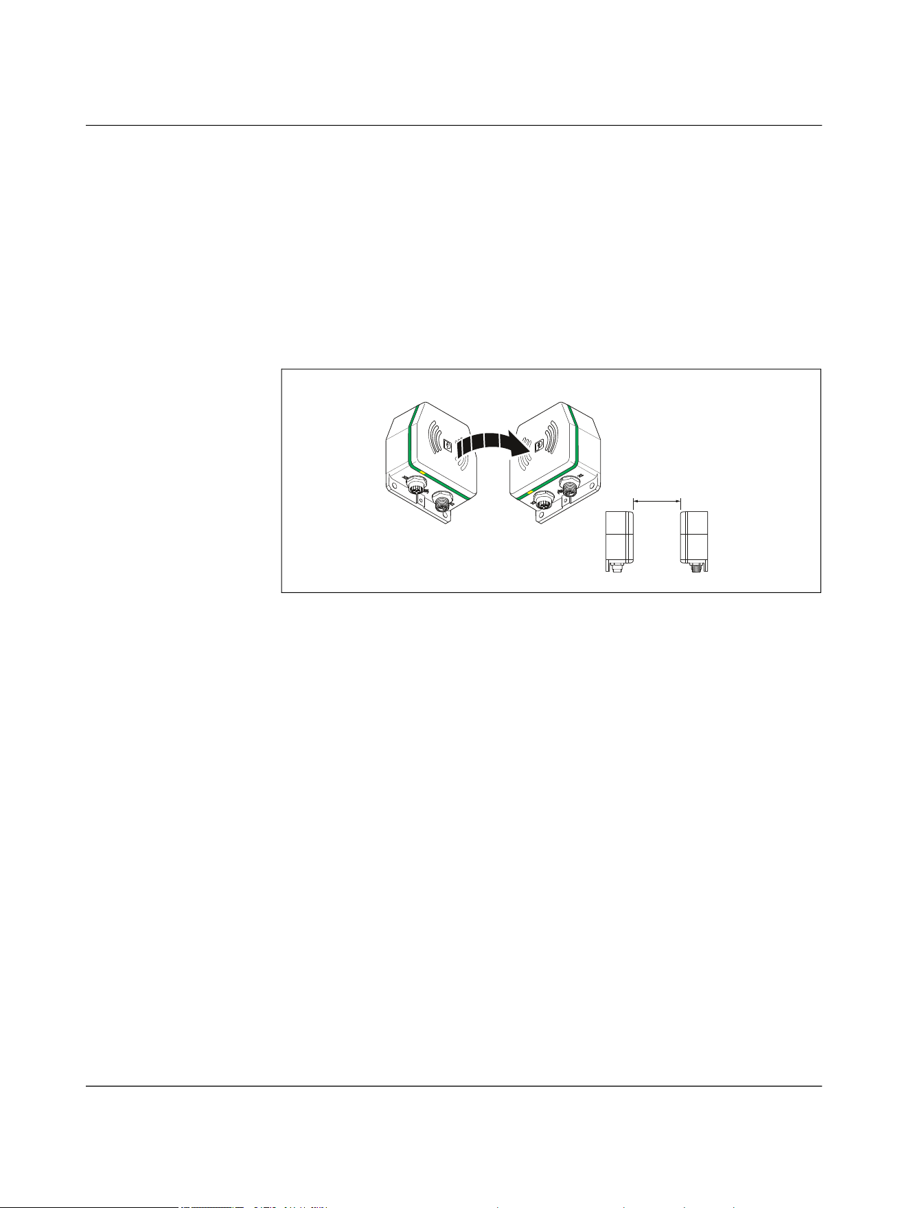
Troubleshooting
110718_en_02 Phoenix Contact 73 / 102
6 Troubleshooting
6.1 Diagnostic LEDs
If the devices are not working as expected, check whether there is any interference in the
surrounding area.
• Next, check the diagnostics LEDs.
Normal mode
Figure 6-1 LED ring in normal operation
a ≤ 10 mm
a
RemoteBase
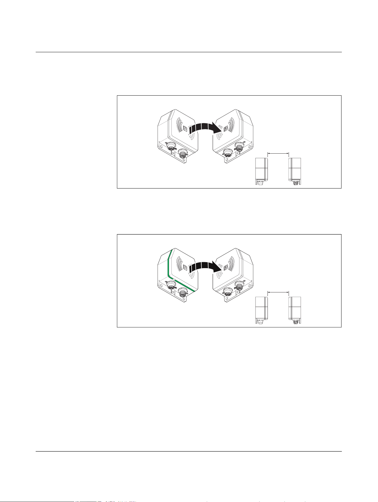
NEARFI
74 / 102 Phoenix Contact
110718_en_02
6.1.1 Base and remote not coupled
Base LED ring is switched off
Figure 6-2 Base not ready for operation
If the base coupler LED ring is switched off, the device is not ready for operation.
• Check the power supply unit.
Remote LED ring is switched off
Figure 6-3 Remote not coupled, overload/short circuit at remote
When the base coupler is supplied with power, it will try to connect to the remote coupler.
The LED ring on the base coupler flashes green. If the LED ring on the remote coupler re-
mains off, the devices are either too far away from each other or there is an overload or
short circuit on the remote coupler.
In this case, the remote coupler automatically switches off the output voltage. It cycli-
cally tries to switch it back on again. The cycle time depends on the output current.
• Check the air gap between the devices.
• Reduce the distance, the offset, or the angle between the devices if necessary.
• Check the connected load on the remote side.
a
RemoteBase
a
RemoteBase
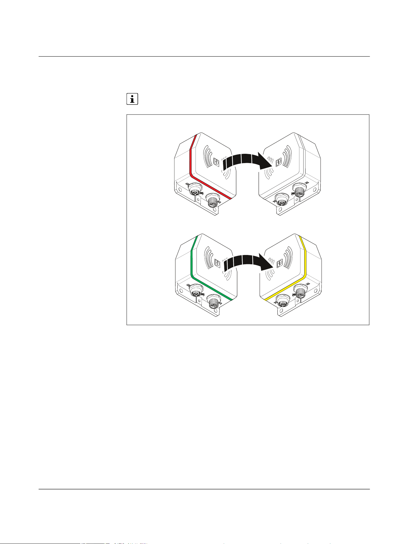
Troubleshooting
110718_en_02 Phoenix Contact 75 / 102
6.1.2 Parallel connection of two NearFi paths
LED ring on the remote coupler flashing yellow
Only for the NEARFI 200 R power coupler
Figure 6-4 Error on remote in parallel operation
When the base coupler is supplied with power, it automatically establishes a connection
to the remote coupler in range.
If one of the two paths connected in parallel is not working correctly, the remote coupler
LED ring flashes yellow. Automatic load distribution may not work. In this case, the re-
mote coupler limits the output to 0 A. It then cyclically attempts to increase the output
current back to 4 A.
One of the two NearFi paths is not working correctly.
• Reduce the distance, the offset, or the angle between the devices if necessary.
• Check the connected load on the remote side.
2200 B 2200 R
200 B 200 R
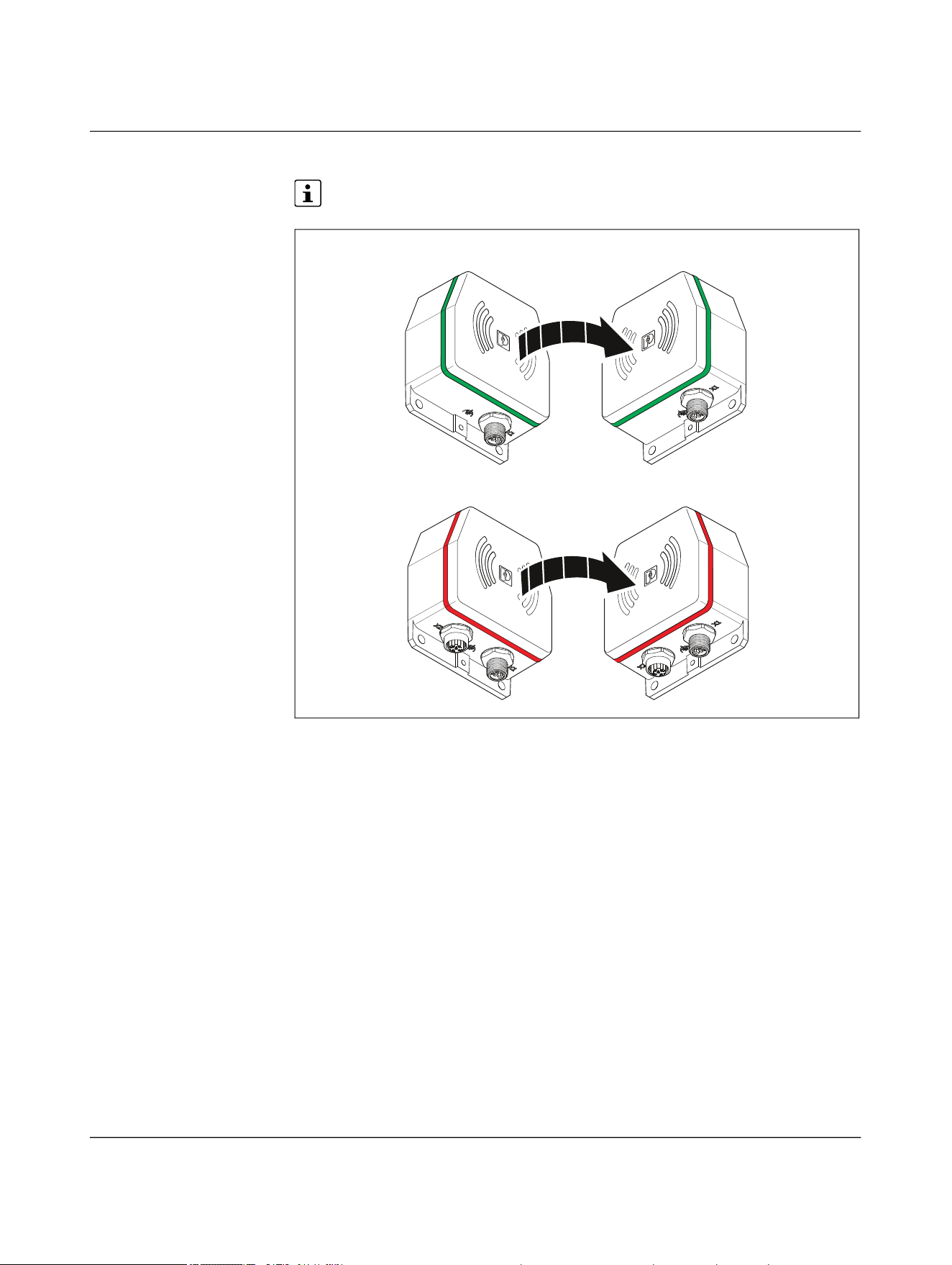
NEARFI
76 / 102 Phoenix Contact
110718_en_02
LED ring on the remote coupler lights up red
Only for the NEARFI 200 R power coupler
Figure 6-5 Critical error on remote in parallel operation
If the remote coupler LED ring lights up red, there is a critical error.
Possible reasons:
– NEARFI 200 B not transmitting power to NEARFI 200 R
– Internal temperature too high
– Internal error
• Check the power supply unit.
• Check the connected load on the remote side.
• Check the air gap between the devices.
• Reduce the distance, the offset, or the angle between the devices if necessary.
• Contact Phoenix Contact if these measures do not help.
2200 B 2200 R
200 B 200 R
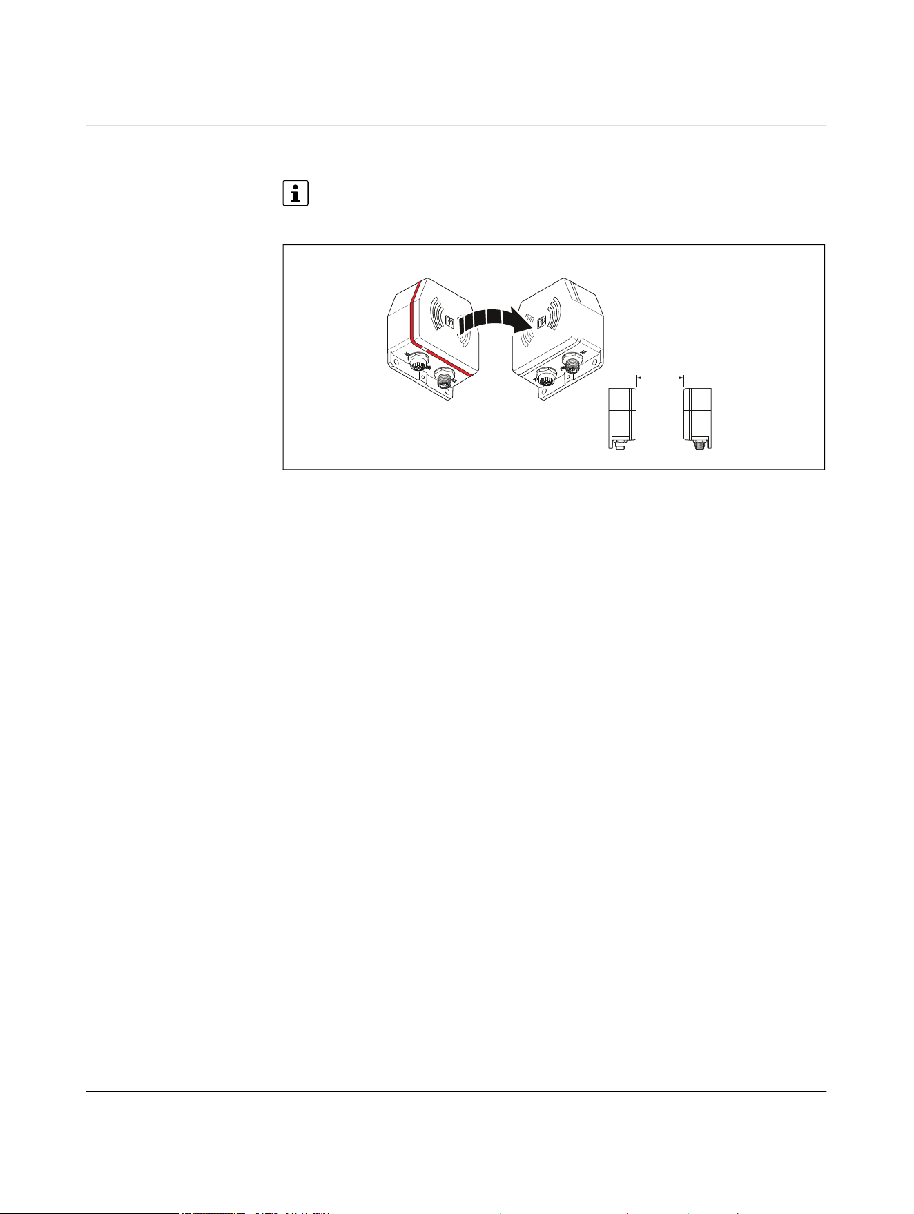
Troubleshooting
110718_en_02 Phoenix Contact 77 / 102
6.1.3 Critical error on the base
Only for the NEARFI 2200 power and data couplers and the NEARFI 200/300 pow-
er couplers
Figure 6-6 Critical error
If the base coupler LED ring lights up red, there is a critical error.
Possible reasons:
– Supply voltage outside of the nominal range (19 V DC ... 30 V DC)
– Internal temperature too high
– Internal error
To protect the coupler and other devices, the remote coupler switches off. No more
power is transmitted.
• Check the power supply unit.
• Check the connected load on the remote side.
• Check the air gap between the devices.
• Reduce the distance, the offset, or the angle between the devices if necessary.
• Contact Phoenix Contact if these measures do not help.
a
RemoteBase
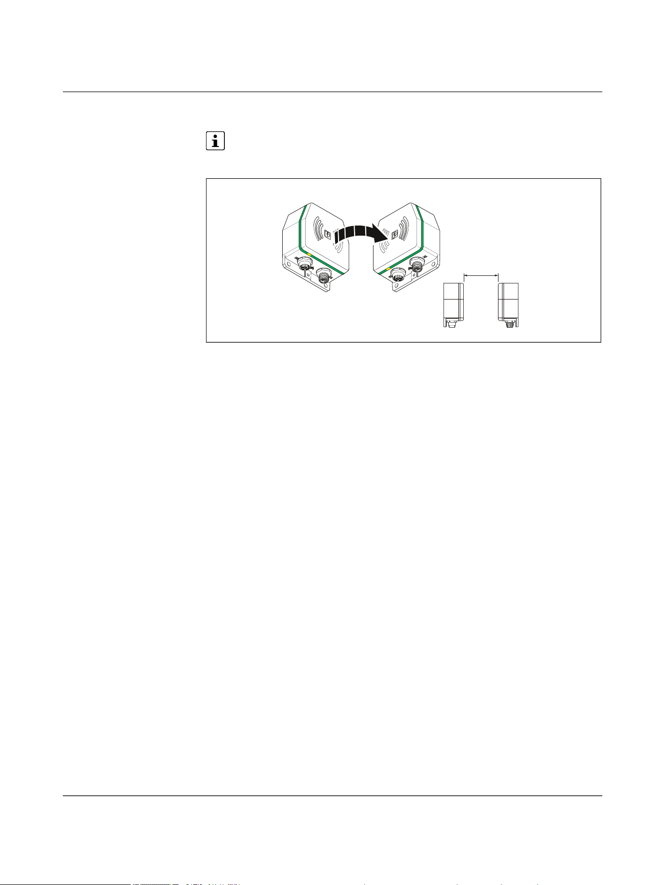
NEARFI
78 / 102 Phoenix Contact
110718_en_02
6.1.4 Malfunction on the data line
Only for the NEARFI 2200 power and data couplers and the NEARFI 2000 data cou-
plers
Figure 6-7 LAN malfunction
If a twisted pair segment malfunctions, only the ETH LINK LED of the corresponding port
will go out.
Fast startup
The “Fast startup” function is also referred to as prioritized startup or fast restart. When
using network devices with this function, note the following:
• Only use routers and switches that support fast startup.
• To ensure fast startup of network devices, select “ETH full duplex” operating mode
on the NearFi couplers.
• Please note that crossover detection is not available in “ETH full duplex” operating
mode. The pin assignment of the network connection changes to “Crossover” on the
remote coupler.
• Select the connecting cable according to the connected device:
– Crossover cable with same port assignment
– Patch cable with different port assignment
a
RemoteBase
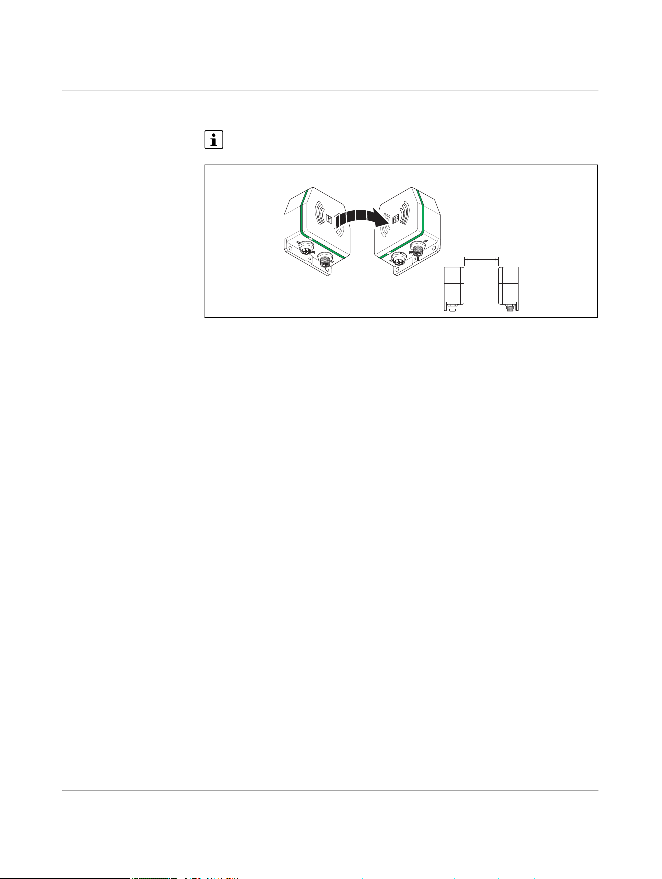
Troubleshooting
110718_en_02 Phoenix Contact 79 / 102
6.1.5 Wireless connection not optimal
Only for the NEARFI 2000 data couplers
Figure 6-8 Wireless connection not optimal
The LED ring on the base and the remote flashes green if the distance or the offset be-
tween the couplers is too great.
• Check the air gap between the devices.
• Reduce the distance, the offset, or the angle between the devices if necessary.
a
RemoteBase

NEARFI
80 / 96 Phoenix Contact
110718_en_02
7 Device replacement, device defect and repair
7.1 Device replacement
NOTE: Device damage
Only mount and remove devices when the power supply is disconnected.
You can replace the device if necessary.
• Disconnect the device from the power supply.
• Remove all cables.
• Remove the device as described in “Mounting and removal” on page 58.
• Replace the device with an identical device (the same item no.).
7.2 Device defect and repair
Repairs may only be carried out by Phoenix Contact.
• Send defective devices back to Phoenix Contact for repair or to receive a replace-
ment device.
• We strongly recommend using the original packaging to return the product.
• Include a note in the packaging indicating that the contents are returned goods.
• Include an error description with the returned product.
• If the original packaging is no longer available, observe the following points:
– Observe the humidity specifications and the temperature range specified for
transport (see “Ambient conditions” on page 91).
– Use dehumidifying agents if necessary.
– Use suitable ESD packaging to protect components that are sensitive to electro-
static discharge.
– Make sure that the packaging you select is large enough and sufficiently thick.
– Only use plastic bubble wrap sheets as wadding.
– Attach warnings to the transport packaging so that they are clearly visible.
– Please ensure that the delivery note is placed inside the package if the package
is to be shipped domestically. However, if the package is being shipped interna-
tionally, the delivery note must be placed inside a delivery note pocket and at-
tached to the outside so that it is clearly visible.

Device replacement, device defect and repair
110718_en_02 Phoenix Contact 81 / 96
8 Maintenance and disposal
8.1 Maintenance
The device is maintenance-free.
8.2 Disposal
The symbol with the crossed-out trash can indicates that this item must be collect-
ed and disposed of separately. Phoenix Contact or our service partners will take the
item back for free disposal. For information on the available disposal options, visit
phoenixcontact.com.
• Set all DIP switches to “off” before disposal.
• Dispose of packaging materials that are no longer needed (cardboard packaging,
paper, bubble wrap sheets, etc.) with household waste in accordance with the
currently applicable national regulations.

NEARFI
82 / 102 Phoenix Contact
110718_en_02
9 Technical data
9.1 Ordering data
NEARFI Type Item no. Pcs./Pkt.
Power and data coupler, 50 W (US), 100 Mbps full
duplex, M12 push-pull, IP65, optional: 100 W (US) in
conjunction with NEARFI 200 or 2 x 50 W (US+UA) with
NEARFI 300
Base coupler NEARFI 2200 B 1433050 1
Remote coupler NEARFI 2200 R 1433049 1
Power coupler, 50 W (UA), M12 push-pull, IP65,
optional: 2 x 50 W (US+UA) in conjunction with
NEARFI 2200/200
Base coupler NEARFI 300 B 1464614 1
Remote coupler NEARFI 300 R 1509989 1
Power coupler, 50 W (US), M12 push-pull, IP65,
optional: 100 W (US) in conjunction with
NEARFI 2200/200 or 2 x 50 W (US+UA) with
NEARFI 300
Base coupler NEARFI 200 B 1433047 1
Remote coupler NEARFI 200 R 1433046 1
Data coupler, 100 Mbps full duplex, range up to 10 cm,
M12 push-pull, IP65
Base coupler NEARFI 2000 B 1433041 1
Remote coupler NEARFI 2000 R 1433040 1

Technical data
110718_en_02 Phoenix Contact 83 / 102
9.1.1 Accessories
Screw plugs Type Item no. Pcs./Pkt.
M12 screw plug for unused M12 females of shielded
sensor/actuator cable, boxes, and flush-type connectors
PROT-M12 SH 1503302 5
Metal M12 sealing cap for unused M12 males of sen-
sor/actuator cables, flush-type connectors, and I/O
devices in the field
PROT-M12 FS-M 1430488 10
M12 sealing cap for unused M12 males of sensor/actua-
tor cables, flush-type connectors, and I/O devices in the
field
PROT-M12 FS 1560251 5
M12 screw plug for unused M12 females of M12 power
connectors, boxes, and flush-type connectors
PROT M12 MS PWR 1092802 5
Power cables and power connectors
Power cable, 4-pos., PUR halogen-free, black gray RAL
7021, coding: L, for DC current up to 12 A/63 V
Free cable end to M12 straight socket
Cable length: 5 m
SAC-4P- 5,0-105/M12FSL 1425035 1
Free cable end to M12 angled socket
Cable length: 5 m
SAC-4P- 5,0-105/M12FRL 1425039 1
M12 straight connector to free cable end
Cable length: 5 m
SAC-4P-M12MSL/ 5,0-105 1425027 1
M12 angled connector to free cable end
Cable length: 5 m
SAC-4P-M12MRL/ 5,0-105 1425031 1
M12 straight connector to M12 straight socket
Cable length: 0.6 m
SAC-4P-M12MSL/0,6-
105/FSL
1425042 1
M12 straight connector to M12 straight socket
Cable length: 3 m
SAC-4P-M12MSL/3,0-
105/FSL
1425044 1
Power connector, power, 4-pos., shielded, coding: L,
Push-Lock spring connection, knurled material: brass,
nickel-plated, outer cable diameter: 6 mm ... 11 mm
M12 straight socket SACC-M12FSL-4PL-CM SH 1080237 1
M12 straight connector SACC-M12MSL-4PL-CM SH 1080239 1

NEARFI
84 / 102 Phoenix Contact
110718_en_02
You will find additional accessories with the product at
phoenixcontact.com/products
.
Network cables
Network cable, Ethernet CAT5 (100 Mbps), 4-pos., PUR
halogen-free, water blue RAL 5021, shielded (Advanced
Shielding Technology), M12 straight push-pull connec-
tor, coding: D/IP67, cable length: 5 m
M12 straight connector to free cable end NBC-P12MSD/ 5,0-93E 1476013 1
M12 straight connector to RJ45 straight connector/IP20 NBC-P12MSD/ 5,0-
93E/R4AC
1476025 1
M12 straight connector to M12 straight connector NBC-P12MSD/ 5,0-
93E/P12MSD
1476051 1
Network cable, PROFINET CAT5 (100 Mbps), EtherCAT®
CAT5 (100 Mbps), 4-pos., PVC/PVC, green RAL 6018,
shielded (Advanced Shielding Technology), M12 straight
connector, coding: D/IP67, cable length: 5 m
M12 straight connector to free cable end NBC-M12MSD/ 5,0-93B 1407497 1
M12 straight connector to RJ45 straight connector/IP20 NBC-M12MSD/ 5,0-
93B/R4AC
1407501 1
M12 straight connector to M12 straight connector NBC-M12MSD/ 5,0-
93B/M12MSD
1407526 1
Network cable, PROFINET CAT5 (100 Mbps), EtherCAT®
CAT5 (100 Mbps), 4-pos., PUR/FRNC halogen-free,
green RAL 6018, shielded (Advanced Shielding Technol-
ogy), M12 angled connector, coding: D/IP67, to M12
angled connector, coding: D/IP67, cable length: 5 m
NBC-M12MRD/ 5,0-
93C/M12MRD
1416749 1
Network connectors
Connector, PROFINET CAT5 (100 Mbps), 4-pos.,
shielded, coding: D, Push-Lock spring connection,
knurled material: zinc die-cast, nickel-plated, outer
cable diameter: 4 mm ... 8 mm
M12 angled connector SACC-M12MRD-4PL SH PN 1424684 1
M12 straight connector SACC-M12MSD-4PL SH PN 1424682 1
RJ45 connector, design: RJ45, degree of protection:
IP20, number of positions: 8, 1 Gbps, CAT5, material:
plastic, connection method: insulation displacement
connection, connection cross-section: AWG 26 ... 23,
cable outlet: straight, color: traffic gray A RAL 7042,
Ethernet
VS-08-RJ45-5-Q/IP20 1656725 1

Technical data
110718_en_02 Phoenix Contact 85 / 102
9.2 Technical data
Coupling system NEARFI 2200 NEARFI 300 NEARFI 200 NEARFI 2000
Product characteristic Power and data
coupler
Power coupler,
actuator supply
Power coupler,
communications
power
Data coupler
Range 0 mm … 10 mm 0 mm … 10 mm 0 mm … 10 mm 0 mm ... 100 mm,
adjustable via DIP
switch
Center offset ±5 mm ±10 mm ±10 mm ± 5 mm (no spac-
ing between the
devices)
± 20 mm (at
100 mm spacing
between the
devices)
Inclination tolerance < 15° < 15° < 15° < 25°
Power transmission
Frequency range 110 kHz ...
148.5 kHz
110 kHz ...
148.5 kHz
110 kHz ...
148.5 kHz
-
Test field strength ~ 1.95 µA/m (at a
10 m distance)
~ 1.95 µA/m (at a
10 m distance)
~ 1.95 µA/m (at a
10 m distance)
-
Output power
Individual operation 50 W
communications
power
50 W
actuator supply
50 W
communications
power
-
Parallel operation 100 W
communications
power, for parallel
operation with
NEARFI 200
50 W
2 x 50 W, commu-
nications power
and actuator sup-
ply electrically iso-
lated, for parallel
operation with
NEARFI 2200/200
100 W
communications
power, for parallel
operation with
NEARFI 2200
-
50 W
2 x 50 W, commu-
nications power
and actuator sup-
ply electrically iso-
lated, for parallel
operation with
NEARFI 300
- 50 W
2 x 50 W, commu-
nications power
and actuator sup-
ply electrically iso-
lated, for parallel
operation with
NEARFI 300
-
Data transmission
Frequency range 59 GHz ... 64 GHz - - 59 GHz ... 64 GHz
Transmission power < 10 mW (EIRP) - - < 10 mW (EIRP)
Delay time ≤ 1 µs (typical) - - ≤ 1 µs (typical)
Bit error rate ≤ 10
-12
(typical) - - ≤ 10
-12
(typical)

NEARFI
86 / 102 Phoenix Contact
110718_en_02
X1, base NEARFI 2200 B NEARFI 300 B NEARFI 200 B NEARFI 2000 B
Interface designation Base power supply Base power supply Base power supply Base power supply
Supply voltage range 19 V DC ... 30 V DC 19 V DC ... 30 V DC 19 V DC ... 30 V DC 19 V DC ... 30 V DC
Typical current consumption
Individual operation 170 mA
without remote
coupler, at
24 V DC, at 25°C
40 mA
without remote
coupler, at
24 V DC, at 25°C
40 mA
without remote
coupler, at
24 V DC, at 25°C
195 mA
at 24 V DC, at 25°C
480 mA
with remote cou-
pler, without load,
at 24 V DC, at 25°C
125 mA
with remote cou-
pler, without load,
at 24 V DC, at 25°C
130 mA
with remote cou-
pler, without load,
at 24 V DC, at 25°C
-
Parallel operation 240 mA
parallel operation
with NEARFI 200,
without remote
coupler, at
24 V DC, at 25°C
- 125 mA
parallel operation
with NEARFI 200,
without remote
coupler, at
24 V DC, at 25°C
-
650 mA
parallel operation
with NEARFI 200,
without remote
coupler, without
load, at 24 V DC, at
25°C
- 330 mA
parallel operation
with NEARFI 200,
without remote
coupler, without
load, at 24 V DC, at
25°C
-
Current consumption, maximum
Individual operation < 3.7 A
with remote cou-
pler, 2 A load,
19 V DC input volt-
age
< 3.2 A
with remote cou-
pler, 2 A load,
19 V DC input volt-
age
< 3.2 A
with remote cou-
pler, 2 A load,
19 V DC input volt-
age
-
Parallel operation < 7.1 A
parallel operation
with NEARFI 200,
with remote cou-
pler, 4 A load,
19 V DC input volt-
age
- < 6.2 A
parallel operation
with NEARFI 200,
with remote cou-
pler, 4 A load,
19 V DC input volt-
age

Technical data
110718_en_02 Phoenix Contact 87 / 102
X1, base NEARFI 2200 B NEARFI 300 B NEARFI 200 B NEARFI 2000 B
Inrush current
Individual operation 1.9 A
for approx. 1.5 ms,
at 24 V DC, without
remote coupler
2.3 A
for approx. 1 ms, at
24 V DC, without
remote coupler
2 A
for approx. 1.5 ms,
at 24 V DC, without
remote coupler
0.4 A
for 0.2 ms at
24 V DC, without
remote coupler
4.3 A
for approx. 4.5 ms,
at 24 V DC, with re-
mote coupler,
without load
4.5 A
for approx. 4.5 ms,
at 24 V DC, with re-
mote coupler,
without load
4.4 A
for approx. 4.5 ms,
at 24 V DC, with re-
mote coupler,
without load
-
Parallel operation 3.9 A
parallel operation
with NEARFI 200,
for approx. 1.5 ms,
at 24 V DC, without
remote coupler
- 3.9 A
parallel operation
with NEARFI 200,
for approx. 1.5 ms,
at 24 V DC, without
remote coupler
-
8.1 A
parallel operation
with NEARFI 200,
for approx. 4.5 ms,
at 24 V DC, with re-
mote coupler,
without load
- 8.1 A
parallel operation
with NEARFI 200,
for approx. 4.5 ms,
at 24 V DC, with re-
mote coupler,
without load
-
Protective circuit Transient protec-
tion, protection
against polarity
reversal
Transient protec-
tion, protection
against polarity
reversal
Transient protec-
tion, protection
against polarity
reversal
Transient protec-
tion, protection
against polarity
reversal
Connection method M12 connector
(L-coded)
Push-pull fast con-
nection or screw
connection
M12 connector
(L-coded)
Push-pull fast con-
nection or screw
connection
M12 connector
(L-coded)
Push-pull fast con-
nection or screw
connection
M12 connector
(L-coded)
Push-pull fast con-
nection or screw
connection

NEARFI
88 / 102 Phoenix Contact
110718_en_02
X1, remote NEARFI 2200 R NEARFI 300 R NEARFI 200 R NEARFI 2000 R
Interface designation Remote output Remote output Remote output Remote power
supply
Nominal output voltage 24 V DC ±5% 24 V DC ±5% 24 V DC ±5% -
Output current
Individual operation ≤ 2 A (typical) ≤ 2 A (typical) ≤ 2 A (typical) -
Parallel operation - - ≤ 4 A (typical,
parallel operation)
-
Maximum output current
Individual operation 3.5 A
peak, for 20 ms,
with 5 mm spacing
4 A
peak, for 20 ms,
with 5 mm spacing
4 A
peak, for 20 ms,
with 5 mm spacing
-
Parallel operation - - 6.8 A
parallel operation,
peak, for 20 ms,
with 5 mm spacing
-
Supply voltage range - - - 19 V DC ... 30 V DC
Typical current consumption - - - ≤ 160 mA
at 24 V DC, at 25°C
Inrush current - - - 0.4 A
for 0.2 ms at
24 V DC, without
remote coupler
Protective circuit Short circuit pro-
tection, overload
protection
Short circuit pro-
tection, overload
protection
Short circuit pro-
tection, overload
protection
Transient protec-
tion,
protection against
polarity reversal
Connection method M12 female,
L-coded
Screw connection
M12 female,
L-coded
Screw connection
M12 female,
L-coded
Screw connection
M12 connector,
L-coded
Push-pull fast con-
nection or screw
connection

Technical data
110718_en_02 Phoenix Contact 89 / 102
X2, remote and base NEARFI 2200 NEARFI 300 NEARFI 200 NEARFI 2000
Designation Ethernet interface,
100Base-T(X) in
accordance with
IEEE 802.3
- - Ethernet interface,
100Base-T(X) in
accordance with
IEEE 802.3
Number of ports 1 - - 1
Connection method M12 female,
D-coded
Push-pull fast con-
nection or screw
connection
- - M12 female,
D-coded
Push-pull fast con-
nection or screw
connection
Note on the connection method Auto negotiation
and auto crossing,
fast startup (FSU,
< 500 ms), LFPT
- - Auto negotiation
and auto crossing,
fast startup (FSU,
< 500 ms), LFPT
Operating mode Full duplex, auto
neg (can be set via
DIP switch)
- - Full duplex, auto
neg (can be set via
DIP switch)
Transmission speed 100 Mbps - - 100 Mbps
Transmission length 100 m (twisted
pair, shielded)
- - 100 m (twisted
pair, shielded)
Transmission medium Copper - - Copper
Supported protocols Protocol-transpar-
ent: PROFINET,
PROFINET IRT,
PROFIsafe,
EtherCAT®,
Modbus/TCP,
Powerlink, TSN,
etc.
- - Protocol-transpar-
ent: PROFINET,
PROFINET IRT,
PROFIsafe,
EtherCAT®,
Modbus/TCP,
Powerlink, TSN,
etc.

NEARFI
90 / 102 Phoenix Contact
110718_en_02
General data
Degree of protection IP65/IP66 (manufacturer’s declaration)
Impact strength IK06
Overvoltage category II
Pollution degree 2
Flammability rating in accordance with UL 94 V0
Mounting position Any
Mounting type Panel mounting
Mounting note Observe derating, see page 53
Dimensions (W/H/D) 80 mm x 86 mm x 39 mm
Material
Enclosure PBT
Enclosure Die-cast zinc
Color
Housing Black (9005)
Other resistance Resistant to welding splash
Vibration resistance in accordance with EN 60068-2-
6/IEC 60068-2-6
5g per spatial direction, 10 Hz ... 150 Hz, amplitude
±0.34 mm
Shock in accordance with EN 60068-2-27/IEC 60068-
2-27
30g, 11 ms duration, half-sine shock pulse, three shocks per
spatial direction
Continuous shock in accordance with EN 60068-2-
27/IEC 60068-2-27
10g, 16 ms duration, half-sine shock pulse, 1000 shocks per
spatial direction
Electromagnetic compatibility Conformance with EMC Directive 2014/30/EU
Free from substances that would hinder coating with
paint or varnish
VDMA 24364:2018:05
MTTF (mean time to failure) NEARFI 2200 NEARFI 300 NEARFI 200 NEARFI 2000
SN 29500 standard, temperature
25°C, operating cycle 21%
126 years 221 years 221 years 191 years
SN 29500 standard, temperature
40°C, operating cycle 34.25%
67 years 112 years 112 years 110 years
SN 29500 standard, temperature
40°C, operating cycle 100%
31 years 51 years 51 years 53 years

Technical data
110718_en_02 Phoenix Contact 91 / 102
Please note that the lower derating value of the respective item version applies for
parallel operation, see 4.15 “Derating”.
Ambient conditions NEARFI 2200 NEARFI 300 NEARFI 200 NEARFI 2000
Ambient temperature
Operation -20°C ... 55°C
(observe derating)
-20°C ... 60°C
(observe derating)
-20°C ... 55°C
(observe derating)
-20°C ... 65°C
(observe derating)
- -20°C ... 40°C (in
accordance with
UL, observe derat-
ing)
-20°C ... 40°C (in
accordance with
UL, observe derat-
ing)
-
Storage/transport -40°C ... 85°C -40°C ... 85°C -40°C ... 85°C -40°C ... 85°C
Humidity
Operation 10% ... 95% 10% ... 95% 10% ... 95% 10% ... 95%
Storage/transport 10% ... 95% 10% ... 95% 10% ... 95% 10% ... 95%
Altitude 2000 m 2000 m 2000 m 2000 m
Air pressure
Operation 80 kPa ... 108 kPa
(up to 2000 m
above mean sea
level)
80 kPa ... 108 kPa
(up to 2000 m
above mean sea
level)
80 kPa ... 108 kPa
(up to 2000 m
above mean sea
level)
80 kPa ... 108 kPa
(up to 2000 m
above mean sea
level)
Storage/transport 66 kPa ... 108 kPa
(up to 3500 m
above mean sea
level)
66 kPa ... 108 kPa
(up to 3500 m
above mean sea
level)
66 kPa ... 108 kPa
(up to 3500 m
above mean sea
level)
66 kPa ... 108 kPa
(up to 3500 m
above mean sea
level)

NEARFI
92 / 102 Phoenix Contact
110718_en_02
Conformity/approvals NEARFI 2200 NEARFI 300 NEARFI 200 NEARFI 2000
CE CE compliant
Wireless approval, Europe RED 2014/53/EU
UL, USA UL 61010
recognized
UL 61010-2-201,
2nd Edition
UL 61010-1,
3rd Edition
E238705
UL 61010 Listed
UL 61010-2-201, 2nd Edition
UL 61010-1, 3rd Edition
E238705
UL, Canada cUL 61010
recognized
CSA C22.2
No. 61010-2-
201:18,
2nd Edition
CSA C22.2 No. 610
10-1, 3rd Edition
E238705
cUL 61010 listed
CSA C22.2 No. 61010-2-201:18, 2nd Edition
CSA C22.2 No. 61010-1, 3rd Edition
E238705
Radio approval for USA, FCC YG32200B
YG32200R
YG3300B
YG3300R
YG3200B
YG3200R
YG32000B
YG32000R

Technical data
110718_en_02 Phoenix Contact 93 / 102
Conformance with EMC Directive 2014/30/EU
Immunity in accordance with EN 61000-6-2
Electrostatic discharge EN 61000-4-2
Contact
discharge
±4 kV (test severity level 2)
Air discharge ±8 kV (test severity level 3)
Comment Criterion B
Electromagnetic HF field EN 61000-4-3
Frequency range 80 MHz ... 1 GHz (test severity level 3)
Field strength 10 V/m
Comment Criterion A
Fast transients (burst) EN 61000-4-4
Input ±2 kV (test severity level 3 - asymmetrical)
Output ±2 kV (test severity level 3 - asymmetrical)
Signal ±2 kV (test severity level 3 - asymmetrical)
Comment Criterion B
Surge current loads (surge) EN 61000-4-5
Input ±0.5 kV (test severity level 1 - symmetrical)
±1 kV (test severity level 2 - asymmetrical)
Output ±1 kV (test severity level 2 - asymmetrical)
Signal ±1 kV (test severity level 2 - asymmetrical)
Comment Criterion B
Conducted influence EN 61000-4-6
Frequency range 0.15 MHz ... 80 MHz (test severity level 3 - asymmetrical)
Voltage 10 V (80% amplitude modulation with 1 kHz)
Comment Criterion A
Criterion A Normal operating behavior within the specified limits
Criterion B Temporary impairment of operating behavior that is corrected by the device itself
Noise emission in accordance with EN 61000-6-4
Interference emission EN 55016-2-3, Class A, industrial area of application
Conducted noise emission EN 55032, Class A, industrial area of application
Conformance with RED Directive 2014/53/EU
Safety – Protection of personnel with regard to electrical
safety
EN 62368
Health – Limiting public exposure to electromagnetic fields EN 62311
Wireless communication – Effective use of the frequency
spectrum and prevention of wireless communication inter-
ference
EN 300330, EN 301417, EN 305550, EN 305550-1,
EN 303396
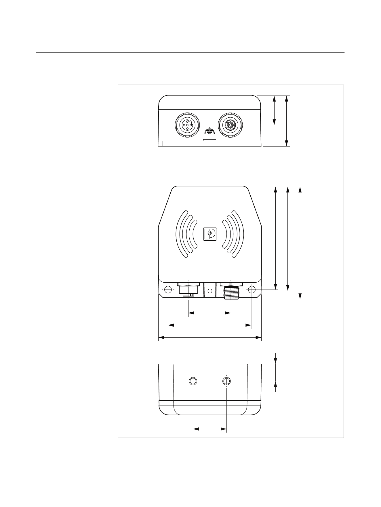
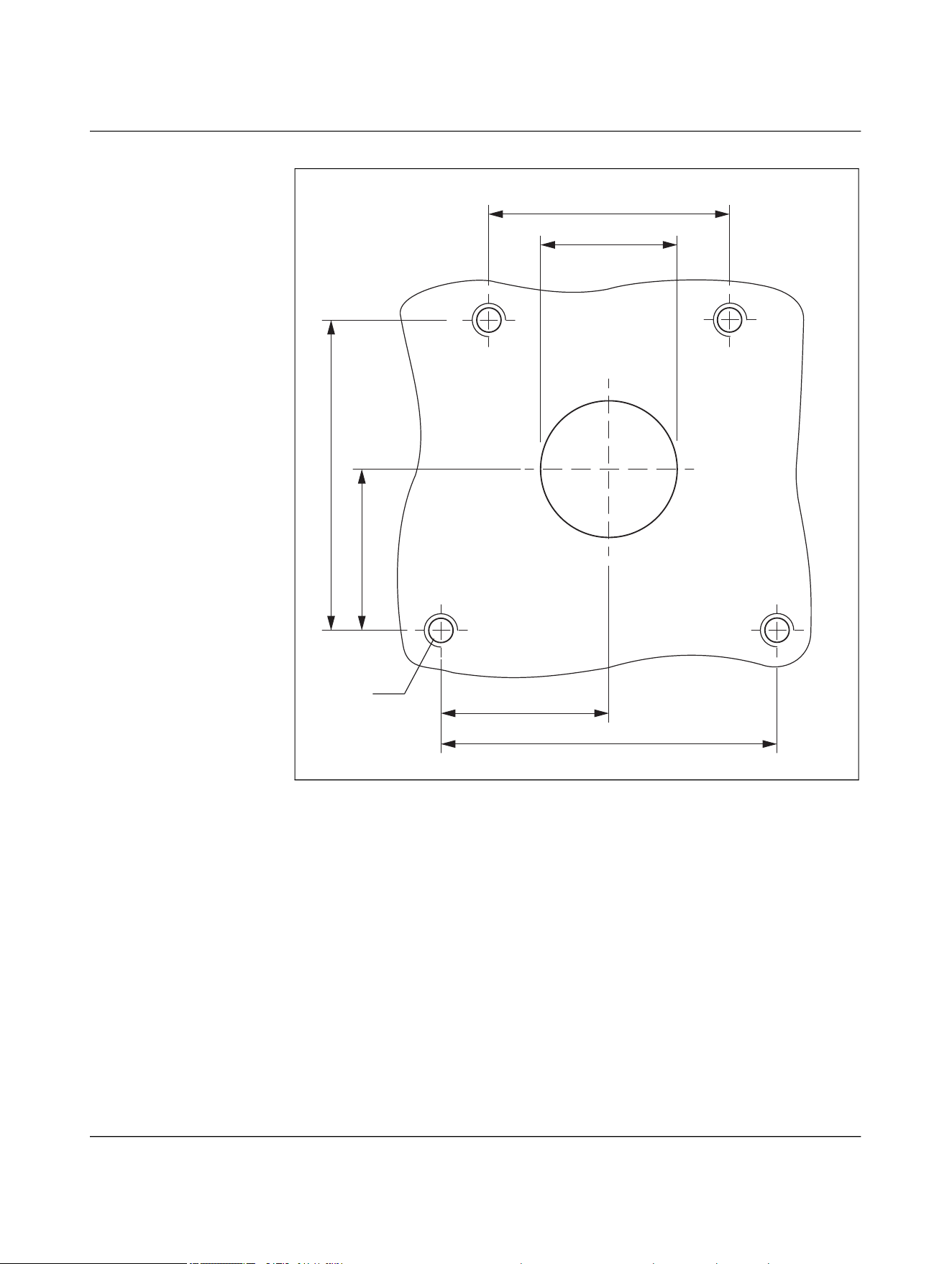


Appendix
110718_en_02 Phoenix Contact 97 / 102
A Appendix
A 1 List of figures
Figure 1-1: Scanning the QR code ............................................................................8
Figure 4-1: Contactless transmission between a controller and a distribu-
ted I/O device with Ethernet interface ............................................... 18
Figure 4-2: Transmission of data and power (US) ................................................. 19
Figure 4-3: Transmission of data and power (US, UA) .......................................... 20
Figure 4-4: Tool change on an industrial robot ..................................................... 21
Figure 4-5: Stand-alone operation, Ethernet 100 Mbps, US 50 W ....................... 24
Figure 4-6: Parallel operation, Ethernet 100 Mbps, US 100 W ............................ 25
Figure 4-7: Parallel operation, US 50 W and UA 50 W .......................................... 26
Figure 4-8: Parallel operation, US 50 W and UA 50 W, detailed view with
pin assignment .................................................................................... 27
Figure 4-9: Stand-alone operation, US 50 W ........................................................ 28
Figure 4-10: Stand-alone operation, UA 50 W ........................................................ 29
Figure 4-11: Parallel operation, US 100 W .............................................................. 30
Figure 4-12: Parallel operation, US 50 W and UA 50 W .......................................... 31
Figure 4-13: Parallel operation, US 50 W and UA 50 W, detailed view with
pin assignment .................................................................................... 32
Figure 4-14: Data transmission ............................................................................... 33
Figure 4-15: Basic circuit diagram of power and data coupler, base ..................... 34
Figure 4-16: Basic circuit diagram of power and data coupler, remote ................. 34
Figure 4-17: Basic circuit diagram of power coupler US, base ............................... 35
Figure 4-18: Basic circuit diagram of power coupler US, remote ........................... 35
Figure 4-19: Basic circuit diagram of power coupler UA, base ............................... 36
Figure 4-20: Basic circuit diagram of power coupler UA, remote ........................... 36
Figure 4-21: Basic circuit diagram of data coupler, base and remote .................... 37
Figure 4-22: Function elements ............................................................................... 38
Figure 4-23: DIP switch ........................................................................................... 40
Figure 4-24: Transmission distance ........................................................................ 45
Figure 4-25: Lateral offset ....................................................................................... 45
Figure 4-26: Angular offset ...................................................................................... 45
Figure 4-27: Transmission distance for lateral offset, NEARFI 2200 .................... 46
Figure 4-28: Transmission distance for angular offset, NEARFI 2200 ................... 46
Figure 4-29: Transmission distance for lateral offset, NEARFI 200/300 ............... 47
Figure 4-30: Transmission distance for angular offset, NEARFI 200/300 ............. 47

NEARFI
98 / 102 Phoenix Contact
110718_en_02
Figure 4-31: Transmission distance for lateral offset, NEARFI 2000 .................... 48
Figure 4-32: Transmission distance for angular offset, NEARFI 2000 ................... 48
Figure 4-33: Minimum distance ............................................................................... 50
Figure 4-34: Metal-free area .................................................................................... 50
Figure 4-35: Frontal linear movement ..................................................................... 51
Figure 4-36: Lateral linear movement ..................................................................... 51
Figure 4-37: Sideways rotation ................................................................................ 51
Figure 4-38: Front linear movement in parallel operation ...................................... 52
Figure 4-39: Lateral linear movement in parallel operation ................................... 52
Figure 4-40: Derating curve ..................................................................................... 53
Figure 4-41: Optimal thermal connection ............................................................... 54
Figure 4-42: Good thermal connection .................................................................... 54
Figure 4-43: Installation example with external heatsink (processing head) ........ 56
Figure 4-44: Adapter ................................................................................................ 56
Figure 4-45: Adapter dimensions ............................................................................ 57
Figure 5-1: Drilling diagram ................................................................................... 59
Figure 5-2: Mounting with two M5 screws ............................................................ 59
Figure 5-3: Drilling diagram ................................................................................... 60
Figure 5-4: Mounting with four M6 screws ............................................................ 60
Figure 5-5: Drilling diagram ................................................................................... 61
Figure 5-6: Mounting with two M6 screws ............................................................ 61
Figure 5-7: Connecting cables ............................................................................... 71
Figure 5-8: Options for functional grounding ........................................................ 72
Figure 6-1: LED ring in normal operation .............................................................. 73
Figure 6-2: Base not ready for operation .............................................................. 74
Figure 6-3: Remote not coupled, overload/short circuit at remote ...................... 74
Figure 6-4: Error on remote in parallel operation ................................................. 75
Figure 6-5: Critical error on remote in parallel operation ..................................... 76
Figure 6-6: Critical error ......................................................................................... 77
Figure 6-7: LAN malfunction .................................................................................. 78
Figure 6-8: Wireless connection not optimal ........................................................ 79
Figure 9-1: Dimensions .......................................................................................... 94
Figure 9-2: Centering template ............................................................................. 95

List of tables
110718_en_02 Phoenix Contact 99 / 102
A 2 List of tables
Table 4-1: Devices used in Figure 4-2................................................................... 19
Table 4-2: Devices used in Figure 4-3................................................................... 20
Table 4-3: LED description: ETH Link.................................................................... 39
Table 4-4: LED ring for power and data coupler and power coupler.................... 39
Table 4-5: LED ring for data coupler ..................................................................... 39
Table 4-6: DIP switch ............................................................................................ 40
Table 5-1: Power IN (X1), M12 male, L-coded ..................................................... 63
Table 5-2: Power OUT (X1), M12 female, L-coded............................................... 63
Table 5-3: Data IN/OUT (X2), M12 female, D-coded............................................ 64
Table 5-4: Power IN (X1), M12 male, L-coded ..................................................... 65
Table 5-5: Power OUT (X2), M12 female, L-coded............................................... 65
Table 5-6: Power OUT (X1), M12 female, L-coded............................................... 66
Table 5-7: Power IN (X2), M12 male, L-coded ..................................................... 66
Table 5-8: Power IN (X1), M12 male, L-coded ..................................................... 67
Table 5-9: Power-OUT (X2), M12 female, L-coded .............................................. 67
Table 5-10: Power OUT (X1), M12 female, L-coded............................................... 68
Table 5-11: Power IN (X2), M12 male, L-coded ..................................................... 68
Table 5-12: Power IN (X1), M12 male, L-coded ..................................................... 69
Table 5-13: Data IN/OUT (X2), M12 female, D-coded............................................ 69
Table 5-14: Circular connectors .............................................................................. 70
Table B-1: Revision history .................................................................................. 100

110718_en_02 Phoenix Contact 100 / 156
B Revision history
Table B-1 Revision history
Document
revision
Production batch V/C of the
product
Date Description
NEARFI...B NEARFI...R
00 00 00 2024-08-30 First publication
01 00 00 2024-11-20 Table 3-4 “LED ring“ revised
Section 3.8 “Switch-on time (operational readi-
ness time“ revised
Figure 3-29 “Transmission distance for lateral off-
set, NEARFI 200/300“ corrected
Bit error rate added to the technical data
02 02 01 2026-04-30 FCC approval, UL approval
Section “Protection against tampering“ added
Section “Derating in accordance with UL“ added
Figure 6-5 “Critical error on remote in parallel op-
eration“ revised
Section “Disposal“ revised

Phoenix Contact 101 / 102
Please observe the following notes
General Terms and Conditions of Use for technical documentation
Phoenix Contact reserves the right to alter, correct, and/or improve the technical docu-
mentation and the products described in the technical documentation at its own discre-
tion and without giving prior notice, insofar as this is reasonable for the user. The same
applies to any changes that serve the purpose of technical progress.
The receipt of technical documentation (in particular user documentation) does not con-
stitute any further duty on the part of Phoenix Contact to furnish information on modifi-
cations to products and/or technical documentation. You are responsible to verify the
suitability and intended use of the products in your specific application, in particular with
regard to observing the applicable standards and regulations. All information made avail-
able in the technical documentation is supplied without any accompanying guarantee,
whether expressly mentioned, implied or tacitly assumed.
In general, the provisions of the current General Terms and Conditions of
Phoenix Contact apply exclusively, in particular as concerns any warranty liability.
This manual, including all illustrations contained herein, is copyright protected. Any
changes to the contents or the publication of extracts of this document are prohibited.
Phoenix Contact reserves the right to register its own intellectual property rights for the
product identifications of Phoenix Contact products that are used here. Registration of
such intellectual property rights by third parties is prohibited.
Other product identifications may be afforded legal protection, even where they may not
be indicated as such.

Phoenix Contact GmbH & Co. KG • Flachsmarktstraße 8 • 32825 Blomberg • Germany
phoenixcontact.com
102 / 102
102
How to contact us
Internet Up-to-date information on Phoenix Contact products and our Terms and Conditions can
be found on the Internet at:
phoenixcontact.com
Make sure you always use the latest documentation.
It can be downloaded at:
phoenixcontact.com/products
Subsidiaries If there are any problems that cannot be solved using the documentation, please contact
your Phoenix Contact subsidiary.
Subsidiary contact information is available at phoenixcontact.com
.
Published by Phoenix Contact GmbH & Co. KG
Flachsmarktstraße 8
32825 Blomberg
GERMANY
Should you have any suggestions or recommendations for improvement of the contents
and layout of our manuals, please send your comments to:
tecdoc@phoenixcontact.com